WO2020149100A1 - ハイブリッドシステム、ハイブリッドシステムの制御装置、および、ハイブリッドシステムの制御方法 - Google Patents
ハイブリッドシステム、ハイブリッドシステムの制御装置、および、ハイブリッドシステムの制御方法 Download PDFInfo
- Publication number
- WO2020149100A1 WO2020149100A1 PCT/JP2019/049948 JP2019049948W WO2020149100A1 WO 2020149100 A1 WO2020149100 A1 WO 2020149100A1 JP 2019049948 W JP2019049948 W JP 2019049948W WO 2020149100 A1 WO2020149100 A1 WO 2020149100A1
- Authority
- WO
- WIPO (PCT)
- Prior art keywords
- power
- engine
- rotation speed
- hybrid system
- target
- Prior art date
- Legal status (The legal status is an assumption and is not a legal conclusion. Google has not performed a legal analysis and makes no representation as to the accuracy of the status listed.)
- Ceased
Links
Images










Classifications
-
- B—PERFORMING OPERATIONS; TRANSPORTING
- B60—VEHICLES IN GENERAL
- B60K—ARRANGEMENT OR MOUNTING OF PROPULSION UNITS OR OF TRANSMISSIONS IN VEHICLES; ARRANGEMENT OR MOUNTING OF PLURAL DIVERSE PRIME-MOVERS IN VEHICLES; AUXILIARY DRIVES FOR VEHICLES; INSTRUMENTATION OR DASHBOARDS FOR VEHICLES; ARRANGEMENTS IN CONNECTION WITH COOLING, AIR INTAKE, GAS EXHAUST OR FUEL SUPPLY OF PROPULSION UNITS IN VEHICLES
- B60K6/00—Arrangement or mounting of plural diverse prime-movers for mutual or common propulsion, e.g. hybrid propulsion systems comprising electric motors and internal combustion engines
- B60K6/20—Arrangement or mounting of plural diverse prime-movers for mutual or common propulsion, e.g. hybrid propulsion systems comprising electric motors and internal combustion engines the prime-movers consisting of electric motors and internal combustion engines, e.g. HEVs
- B60K6/42—Arrangement or mounting of plural diverse prime-movers for mutual or common propulsion, e.g. hybrid propulsion systems comprising electric motors and internal combustion engines the prime-movers consisting of electric motors and internal combustion engines, e.g. HEVs characterised by the architecture of the hybrid electric vehicle
- B60K6/46—Series type
-
- B—PERFORMING OPERATIONS; TRANSPORTING
- B60—VEHICLES IN GENERAL
- B60L—PROPULSION OF ELECTRICALLY-PROPELLED VEHICLES; SUPPLYING ELECTRIC POWER FOR AUXILIARY EQUIPMENT OF ELECTRICALLY-PROPELLED VEHICLES; ELECTRODYNAMIC BRAKE SYSTEMS FOR VEHICLES IN GENERAL; MAGNETIC SUSPENSION OR LEVITATION FOR VEHICLES; MONITORING OPERATING VARIABLES OF ELECTRICALLY-PROPELLED VEHICLES; ELECTRIC SAFETY DEVICES FOR ELECTRICALLY-PROPELLED VEHICLES
- B60L50/00—Electric propulsion with power supplied within the vehicle
- B60L50/10—Electric propulsion with power supplied within the vehicle using propulsion power supplied by engine-driven generators, e.g. generators driven by combustion engines
- B60L50/16—Electric propulsion with power supplied within the vehicle using propulsion power supplied by engine-driven generators, e.g. generators driven by combustion engines with provision for separate direct mechanical propulsion
-
- B—PERFORMING OPERATIONS; TRANSPORTING
- B60—VEHICLES IN GENERAL
- B60L—PROPULSION OF ELECTRICALLY-PROPELLED VEHICLES; SUPPLYING ELECTRIC POWER FOR AUXILIARY EQUIPMENT OF ELECTRICALLY-PROPELLED VEHICLES; ELECTRODYNAMIC BRAKE SYSTEMS FOR VEHICLES IN GENERAL; MAGNETIC SUSPENSION OR LEVITATION FOR VEHICLES; MONITORING OPERATING VARIABLES OF ELECTRICALLY-PROPELLED VEHICLES; ELECTRIC SAFETY DEVICES FOR ELECTRICALLY-PROPELLED VEHICLES
- B60L50/00—Electric propulsion with power supplied within the vehicle
- B60L50/50—Electric propulsion with power supplied within the vehicle using propulsion power supplied by batteries or fuel cells
- B60L50/60—Electric propulsion with power supplied within the vehicle using propulsion power supplied by batteries or fuel cells using power supplied by batteries
- B60L50/61—Electric propulsion with power supplied within the vehicle using propulsion power supplied by batteries or fuel cells using power supplied by batteries by batteries charged by engine-driven generators, e.g. series hybrid electric vehicles
-
- B—PERFORMING OPERATIONS; TRANSPORTING
- B60—VEHICLES IN GENERAL
- B60W—CONJOINT CONTROL OF VEHICLE SUB-UNITS OF DIFFERENT TYPE OR DIFFERENT FUNCTION; CONTROL SYSTEMS SPECIALLY ADAPTED FOR HYBRID VEHICLES; ROAD VEHICLE DRIVE CONTROL SYSTEMS FOR PURPOSES NOT RELATED TO THE CONTROL OF A PARTICULAR SUB-UNIT
- B60W10/00—Conjoint control of vehicle sub-units of different type or different function
- B60W10/04—Conjoint control of vehicle sub-units of different type or different function including control of propulsion units
- B60W10/06—Conjoint control of vehicle sub-units of different type or different function including control of propulsion units including control of combustion engines
-
- B—PERFORMING OPERATIONS; TRANSPORTING
- B60—VEHICLES IN GENERAL
- B60W—CONJOINT CONTROL OF VEHICLE SUB-UNITS OF DIFFERENT TYPE OR DIFFERENT FUNCTION; CONTROL SYSTEMS SPECIALLY ADAPTED FOR HYBRID VEHICLES; ROAD VEHICLE DRIVE CONTROL SYSTEMS FOR PURPOSES NOT RELATED TO THE CONTROL OF A PARTICULAR SUB-UNIT
- B60W10/00—Conjoint control of vehicle sub-units of different type or different function
- B60W10/04—Conjoint control of vehicle sub-units of different type or different function including control of propulsion units
- B60W10/08—Conjoint control of vehicle sub-units of different type or different function including control of propulsion units including control of electric propulsion units, e.g. motors or generators
-
- B—PERFORMING OPERATIONS; TRANSPORTING
- B60—VEHICLES IN GENERAL
- B60W—CONJOINT CONTROL OF VEHICLE SUB-UNITS OF DIFFERENT TYPE OR DIFFERENT FUNCTION; CONTROL SYSTEMS SPECIALLY ADAPTED FOR HYBRID VEHICLES; ROAD VEHICLE DRIVE CONTROL SYSTEMS FOR PURPOSES NOT RELATED TO THE CONTROL OF A PARTICULAR SUB-UNIT
- B60W20/00—Control systems specially adapted for hybrid vehicles
- B60W20/10—Controlling the power contribution of each of the prime movers to meet required power demand
-
- B—PERFORMING OPERATIONS; TRANSPORTING
- B60—VEHICLES IN GENERAL
- B60W—CONJOINT CONTROL OF VEHICLE SUB-UNITS OF DIFFERENT TYPE OR DIFFERENT FUNCTION; CONTROL SYSTEMS SPECIALLY ADAPTED FOR HYBRID VEHICLES; ROAD VEHICLE DRIVE CONTROL SYSTEMS FOR PURPOSES NOT RELATED TO THE CONTROL OF A PARTICULAR SUB-UNIT
- B60W20/00—Control systems specially adapted for hybrid vehicles
- B60W20/10—Controlling the power contribution of each of the prime movers to meet required power demand
- B60W20/15—Control strategies specially adapted for achieving a particular effect
- B60W20/16—Control strategies specially adapted for achieving a particular effect for reducing engine exhaust emissions
-
- F—MECHANICAL ENGINEERING; LIGHTING; HEATING; WEAPONS; BLASTING
- F02—COMBUSTION ENGINES; HOT-GAS OR COMBUSTION-PRODUCT ENGINE PLANTS
- F02D—CONTROLLING COMBUSTION ENGINES
- F02D29/00—Controlling engines, such controlling being peculiar to the devices driven thereby, the devices being other than parts or accessories essential to engine operation, e.g. controlling of engines by signals external thereto
- F02D29/06—Controlling engines, such controlling being peculiar to the devices driven thereby, the devices being other than parts or accessories essential to engine operation, e.g. controlling of engines by signals external thereto peculiar to engines driving electric generators
-
- Y—GENERAL TAGGING OF NEW TECHNOLOGICAL DEVELOPMENTS; GENERAL TAGGING OF CROSS-SECTIONAL TECHNOLOGIES SPANNING OVER SEVERAL SECTIONS OF THE IPC; TECHNICAL SUBJECTS COVERED BY FORMER USPC CROSS-REFERENCE ART COLLECTIONS [XRACs] AND DIGESTS
- Y02—TECHNOLOGIES OR APPLICATIONS FOR MITIGATION OR ADAPTATION AGAINST CLIMATE CHANGE
- Y02T—CLIMATE CHANGE MITIGATION TECHNOLOGIES RELATED TO TRANSPORTATION
- Y02T10/00—Road transport of goods or passengers
- Y02T10/60—Other road transportation technologies with climate change mitigation effect
- Y02T10/62—Hybrid vehicles
-
- Y—GENERAL TAGGING OF NEW TECHNOLOGICAL DEVELOPMENTS; GENERAL TAGGING OF CROSS-SECTIONAL TECHNOLOGIES SPANNING OVER SEVERAL SECTIONS OF THE IPC; TECHNICAL SUBJECTS COVERED BY FORMER USPC CROSS-REFERENCE ART COLLECTIONS [XRACs] AND DIGESTS
- Y02—TECHNOLOGIES OR APPLICATIONS FOR MITIGATION OR ADAPTATION AGAINST CLIMATE CHANGE
- Y02T—CLIMATE CHANGE MITIGATION TECHNOLOGIES RELATED TO TRANSPORTATION
- Y02T10/00—Road transport of goods or passengers
- Y02T10/60—Other road transportation technologies with climate change mitigation effect
- Y02T10/70—Energy storage systems for electromobility, e.g. batteries
-
- Y—GENERAL TAGGING OF NEW TECHNOLOGICAL DEVELOPMENTS; GENERAL TAGGING OF CROSS-SECTIONAL TECHNOLOGIES SPANNING OVER SEVERAL SECTIONS OF THE IPC; TECHNICAL SUBJECTS COVERED BY FORMER USPC CROSS-REFERENCE ART COLLECTIONS [XRACs] AND DIGESTS
- Y02—TECHNOLOGIES OR APPLICATIONS FOR MITIGATION OR ADAPTATION AGAINST CLIMATE CHANGE
- Y02T—CLIMATE CHANGE MITIGATION TECHNOLOGIES RELATED TO TRANSPORTATION
- Y02T10/00—Road transport of goods or passengers
- Y02T10/60—Other road transportation technologies with climate change mitigation effect
- Y02T10/7072—Electromobility specific charging systems or methods for batteries, ultracapacitors, supercapacitors or double-layer capacitors
Definitions
- the present disclosure relates to a hybrid system, a hybrid system control device, and a hybrid system control method, and more particularly, to a hybrid system mounted on a vehicle driven by an electric motor using electric power generated by using power of an internal combustion engine.
- the present invention relates to a hybrid system control device and a hybrid system control method.
- the present disclosure has been made to solve the above problems, and an object thereof is to provide a hybrid system capable of reducing the emission of black smoke and nitrogen oxides, a control device for the hybrid system, and a hybrid system. It is to provide a control method of the system.
- a hybrid system includes an internal combustion engine, a generator that generates electric power using power output from the internal combustion engine, a power storage device that charges power generated by the power generator, discharge power of the power storage device, and a power generator.
- An electric motor for driving a vehicle that is driven by using at least one of the generated electric power, and a control that controls so as to limit at least one of a target rotational speed change rate and a target output torque change rate of the internal combustion engine.
- a device includes an internal combustion engine, a generator that generates electric power using power output from the internal combustion engine, a power storage device that charges power generated by the power generator, discharge power of the power storage device, and a power generator.
- control device is configured such that at least one of the rate of change of the target rotational speed of the internal combustion engine and the rate of change of the target output torque is such that the rate of change in which black smoke is discharged in excess of the first predetermined amount and nitrogen oxide are The change is restricted so as to be smaller than at least one of the change rates that is discharged more than the second predetermined amount.
- control device controls at least one of the change rate of the target rotation speed and the change rate of the target output torque of the internal combustion engine using a predetermined control map.
- control device reduces at least one of the change rate of the target rotation speed of the internal combustion engine and the change rate of the target output torque when the SOC of the power storage device is higher than a predetermined value, as compared with the case where the SOC is low. To do so.
- control map includes a map that can specify the rotation speed from the required power to the generator and the vehicle speed, and a map that can specify the target output torque from the required power to the generator and the target rotation speed.
- control map includes a region in which power generation is prioritized over control that limits at least one of the change rate of the target rotation speed and the change rate of the target output torque of the internal combustion engine.
- a control device for a hybrid system is an internal combustion engine, a generator that generates power by using power output from the internal combustion engine, a power storage device that charges power generated by the power generator, and a power storage device.
- a control device for controlling a hybrid system including a motor for driving a vehicle, which is driven by using at least one of the discharge power of the above and the power generated by the generator.
- the control device controls so as to limit at least one of the rate of change of the target rotation speed of the internal combustion engine and the rate of change of the target output torque.
- a control method for a hybrid system is an internal combustion engine, a generator that generates power by using power output from the internal combustion engine, a power storage device that charges power generated by the power generator, and a power storage device. It is a control method by a control device for controlling a hybrid system including a vehicle driving electric motor that is driven by using at least one of electric power discharged from the device and electric power generated by a generator.
- the control method includes a step in which the control device controls so as to limit at least one of a change rate of the target rotation speed of the internal combustion engine and a change rate of the target output torque.
- At least one of the target engine speed change rate and the target output torque change rate of the internal combustion engine is limited in the hybrid system.
- FIG. 1 is a diagram showing a schematic configuration of a vehicle 100 in this embodiment.
- a vehicle 100 includes a battery 10, a power control unit (hereinafter, referred to as “PCU (Power Control Unit)”) 11, an engine 20, and a motor generator (hereinafter, “MG (Motor Generator)”). 31), the MG 32, and the drive wheels 40.
- the vehicle 100 further includes various electronic control units (ECU: Electronic Control Unit) such as an HV-ECU 51 and an EG-ECU 52 described later.
- ECU Electronic Control Unit
- the battery 10 according to the present embodiment corresponds to an example of the “power storage device” according to the present disclosure.
- the engine 20 is an internal combustion engine that outputs power by converting combustion energy generated when fuel (gasoline, light oil, etc.) is burned into kinetic energy of a moving element such as a piston or a crankshaft.
- MG31 and MG32 are electric power devices that convert electric energy into mechanical energy or convert mechanical energy into electric energy.
- a diesel engine is adopted as engine 20
- a three-phase AC synchronous motor generator in which permanent magnets are embedded in rotors is adopted as MG31 and MG32.
- the engine 20 may include a turbocharger (for example, a variable nozzle turbo) in the intake/exhaust system.
- Vehicle 100 is a series hybrid vehicle.
- MG 31 running motor
- MG 32 drives drive wheels 40 by operating as an electric motor
- MG 32 is driven by engine 20 to generate electric power.
- Power sources for driving MG 31 are electric power generated by MG 32 and electric power stored in battery 10. More specifically, the rotary shaft 21 of the engine 20 and the rotary shaft 22 of the MG 32 are mechanically connected to each other via a gear 23, and the rotary shaft 22 of the MG 32 also rotates with the rotation of the rotary shaft 21 of the engine 20. It rotates and the MG 32 generates electricity.
- the rotary shaft 41 of the MG 31 is not mechanically connected to the rotary shafts 21 and 22, but is mechanically connected to the drive shaft 42 via the power transmission gear 43.
- the torque (driving force) output to the rotating shaft 41 of the MG 31 is transmitted to the driving shaft 42 via the power transmission gear 43, and the driving force of the MG 31 causes the driving shaft 42 to rotate.
- the drive wheels 40 provided at both ends of the drive shaft 42 rotate.
- the MG 31 operates as an electric motor during acceleration of the vehicle 100, and drives the drive wheels 40 of the vehicle 100. On the other hand, when the vehicle 100 is being braked or the acceleration on the down slope is being reduced, the MG 31 operates as a generator to perform regenerative power generation. The electric power generated by MG 31 is supplied to battery 10 via PCU 11.
- the MG 32 is configured to generate power (engine power generation) using the power output from the engine 20.
- the engine-generated electric power generated in MG 32 is supplied from MG 32 to MG 31, or is supplied from MG 32 to battery 10 via PCU 11.
- PCU 11 is configured to include two inverters provided corresponding to MG31 and MG32, and a boost converter that boosts the DC voltage supplied to each inverter to the voltage of battery 10 or higher (for example, 600V). PCU 11 executes electric power conversion between battery 10 and MG31 and MG32 in accordance with a control signal from HV-ECU 51. The PCU 11 is configured to be able to control the states of the MG 31 and the MG 32 separately.
- the battery 10 is a rechargeable DC power supply.
- the rated voltage of the battery 10 is, for example, 300V to 450V.
- the battery 10 includes, for example, a secondary battery (rechargeable battery).
- a lithium ion battery can be adopted.
- Battery 10 may include an assembled battery including a plurality of secondary batteries (for example, lithium ion batteries) connected in series and/or in parallel.
- the secondary battery forming the battery 10 is not limited to the lithium ion battery, and another secondary battery (for example, a nickel hydrogen battery) may be adopted.
- An electrolytic solution type secondary battery may be adopted, or an all solid state type secondary battery may be adopted.
- a large-capacity capacitor or the like can be adopted.
- a monitoring unit 61 that monitors the state of the battery 10 is provided for the battery 10.
- the monitoring unit 61 includes various sensors that detect the state of the battery 10 (temperature, current, voltage, etc.).
- the HV-ECU 51 is configured to detect the state (SOC or the like) of the battery 10 based on the output of the monitoring unit 61.
- SOC State Of Charge
- SOC indicates the remaining charge amount, for example, the ratio of the current charge amount to the charge amount in the fully charged state is represented by 0 to 100%.
- various known methods such as a method by current value integration (Coulomb count) or a method by estimating open circuit voltage (OCV: Open Circuit) can be adopted.
- a monitoring unit 62 that monitors the state of the engine 20 is provided for the engine 20.
- the monitoring unit 62 includes various sensors that detect the state of the engine 20 (cooling water temperature, intake air amount, rotational speed, etc.).
- the HV-ECU 51 and the EG-ECU 52 are configured to detect the state of the engine 20 based on the output of the monitoring unit 62.
- monitoring units 63 and 64 for monitoring the states of the MG 31 and MG 32 are provided for the MG 31 and MG 32, respectively.
- Monitoring units 63 and 64 include various sensors that detect the states (temperature, rotation speed, etc.) of MG31 and MG32.
- HV-ECU 51 is configured to detect the states of MG31 and MG32 based on the outputs of monitoring units 63 and 64.
- Each of the ECUs (HV-ECU 51, EG-ECU 52) included in the vehicle 100 includes a CPU (Central Processing Unit) as an arithmetic unit, a storage device, and an input/output port for inputting/outputting various signals (both are shown in FIG. (Not shown).
- the storage device includes a RAM (Random Access Memory) as a working memory and a storage for storage (ROM (Read Only Memory), rewritable nonvolatile memory, etc.).
- Each ECU receives signals from various devices (sensors and the like) connected to the input port and controls various devices connected to the output port based on the received signals.
- Various controls are executed by the CPU executing the programs stored in the storage device.
- each ECU is not limited to the processing by software, and may be performed by dedicated hardware (electronic circuit).
- the HV-ECU 51 and the EG-ECU 52 according to the present embodiment function as the “control device” according to the present disclosure.
- the HV-ECU 51 calculates an output request value for the engine 20 and an output request value for the MG 31 and MG 32 (for example, a torque request value). Then, HV-ECU 51 transmits an output request value for engine 20 to EG-ECU 52, and supplies power to MG 31 and MG 32 based on the output request value for MG 31 and MG 32 (and thus output torque of MG 31 and MG 32 ). To control.
- the HV-ECU 51 can control the magnitude (amplitude) and the frequency of the electric power supplied to the MG 31 and the MG 32 by controlling the PCU 11 and the like. Further, the HV-ECU 51 controls the charge/discharge of the battery 10 by controlling the PCU 11 and the like.
- Various devices connected to the input port of the HV-ECU 51 further include an accelerator opening sensor 65 and a vehicle speed sensor 66 in addition to the various sensors included in the monitoring units 61, 63, 64.
- the accelerator opening sensor 65 detects the amount of depression of an accelerator pedal (not shown) of the vehicle 100 as the accelerator opening, and outputs the detection result (a signal indicating the accelerator opening) to the HV-ECU 51.
- the HV-ECU 51 increases the driving force of the MG 31 as the depression amount of the accelerator pedal increases.
- the vehicle speed sensor 66 detects the speed of the vehicle 100 and outputs the detection result (a signal indicating the vehicle speed) to the HV-ECU 51.
- the EG-ECU 52 receives the output request value for the engine 20 from the HV-ECU 51, and controls the operation of the engine 20 (fuel injection control, ignition control, so that kinetic energy corresponding to the output request value is generated in the engine 20). Intake air amount adjustment control, etc.). Engine power generation is performed by driving the engine 20, and the engine 20 is stopped when the engine power generation is not performed. By driving engine 20, MG 32 generates engine-generated electric power. Further, the EG-ECU 52 receives the detection values of various sensors included in the monitoring unit 62 and transmits the detection values to the HV-ECU 51.
- the vehicle 100 travels when the MG 31 drives the drive wheels 40.
- the HV-ECU 51 starts charging the battery 10 with the engine-generated power when the SOC of the battery 10 becomes equal to or lower than the charge start SOC while the vehicle 100 is traveling, and the SOC of the battery 10 becomes equal to or higher than the charge completion SOC. If so, the charging is stopped.
- the HV-ECU 51 requests the EG-ECU 52 to drive the engine 20 under a predetermined condition suitable for power generation.
- the MG 32 generates engine generated electric power larger than the electric power consumed when the vehicle 100 travels.
- the HV-ECU 51 controls the PCU 11 and the like to supply the generated engine generated electric power to the battery 10. As a result, the battery 10 is charged by the engine-generated power, and the SOC of the battery 10 increases.
- the HV-ECU 51 instructs the EG-ECU 52 to stop the engine 20, and also controls the PCU 11 etc. to stop the supply of electric power to the battery 10.
- the engine 20 is started every time the SOC of the battery 10 becomes equal to or lower than the charge start SOC, and the battery 10 is charged by the engine generated power.
- the SOC of the battery 10 is generally maintained within the range from the charging start SOC to the charging completion SOC.
- vehicle 100 includes a DPF (Diesel Particulate Filter) 71 and an NSR (NOx Storage Reduction) catalyst 72 as a device that processes the exhaust gas of engine 20. Exhaust pipes are connected between the engine 20, the DPF 71, and the NSR catalyst 72.
- DPF Diesel Particulate Filter
- NSR NOx Storage Reduction
- An exhaust temperature sensor 81 and an A/F sensor 82 are provided in the exhaust pipe between the engine 20 and the DPF 71.
- the exhaust temperature sensor 81 detects the temperature of the exhaust gas from the engine 20 and outputs the detection result (a signal indicating the exhaust temperature) to the EG-ECU 52.
- the A/F sensor 82 analyzes the exhaust gas from the engine 20 to detect the air-fuel ratio, and outputs the detection result (a signal indicating the air-fuel ratio) to the EG-ECU 52.
- the DPF 71 is a filter that traps particulate matter (PM: Particulate Matter) contained in the exhaust flowing through the exhaust passage of the engine 20.
- PM particulate Matter
- the collected PM accumulates inside the DPF 71. Therefore, the DPF 71 is regenerated by periodically heating the inside of the DPF 71 to burn and remove PM.
- the NSR catalyst 72 is an occlusion-reduction type NOx catalyst, and uses, for example, alumina (Al 2 O 3 ) as a carrier, and potassium (K), sodium (Na), lithium (Li), cesium Cs, etc. are used on the carrier. It is constituted by carrying a strong alkali metal, an alkaline earth such as barium Ba and calcium Ca, a rare earth such as lanthanum (La) and yttrium (Y), and a noble metal such as platinum Pt.
- alumina Al 2 O 3
- K potassium
- Na sodium
- Li lithium
- cesium Cs cesium Cs, etc.
- It is constituted by carrying a strong alkali metal, an alkaline earth such as barium Ba and calcium Ca, a rare earth such as lanthanum (La) and yttrium (Y), and a noble metal such as platinum Pt.
- the NSR catalyst 72 absorbs NOx when a large amount of oxygen is present in the exhaust gas, the oxygen concentration in the exhaust gas is low, and the reducing component (for example, unburned component (HC) of the fuel) is large. When present, NOx is reduced to NO 2 or NO and released. NOx released as NO 2 or NO is further reduced to N 2 by rapidly reacting with HC or CO in the exhaust gas.
- HC and CO reduce NO 2 and NO, and are themselves oxidized to H 2 O and CO 2 . That is, by appropriately adjusting the oxygen concentration and the HC component in the exhaust introduced into the NSR catalyst 72, it is possible to purify HC, CO, and NOx in the exhaust.
- a NOx sensor 83 is provided in the exhaust pipe downstream of the NSR catalyst 72.
- the NOx sensor 83 detects the amount of NOx contained in the exhaust gas emitted from the NSR catalyst 72, and outputs the detection result (a signal indicating the amount of NOx) to the EG-ECU 52.
- the HV-ECU 51 and the EG-ECU 52 perform control so as to limit the change rates of the target rotation speed and the target output torque of the engine 20. As a result, the amount of smoke and NOx emissions can be reduced.
- FIG. 2 is a flowchart showing the flow of engine control processing in this embodiment.
- the engine control process is called from the main process at predetermined control cycles and is executed by the EG-ECU 52.
- EG-ECU 52 calculates required power for power generation by MG 32 according to vehicle speed, SOC, accelerator opening, etc. (step (hereinafter referred to as “S”) 101).
- S vehicle speed
- SOC accelerator opening, etc.
- This required power is the power required to drive the vehicle 100 according to the accelerator opening degree and the like.
- the SOC of the battery 10 exceeds the charge completion SOC, the required power is set to 0.
- the engine 20 is stopped.
- the SOC of the battery 10 falls below the charge start SOC, the required power is calculated and a power generation request is issued.
- the EG-ECU 52 determines whether or not there is a power generation request, that is, whether or not the required power is 0 (S102). When it is determined that there is no power generation request (NO in S102), the EG-ECU 52 returns the process to be executed to the calling source of this process.
- the EG-ECU 52 calculates the target rotation speed of the engine 20 according to the vehicle speed and the required power (S103). Calculation of the target rotation speed will be described later with reference to FIG. Next, the EG-ECU 52 calculates the target output of the engine 20 according to the target rotation speed and the vehicle speed (S104). The calculation of the target output will be described later with reference to FIG. The EG-ECU 52 controls the engine 20 so that the calculated target rotation speed and target output are obtained (S105), and the EG-ECU 52 returns the processing to be executed to the processing that is the calling source of this processing.
- the control of the rotation speed and the output of the engine 20 is executed by controlling the rotation speed with the MG 32, for example. Specifically, when the rotation speed is set to a high target rotation speed, first, the PCU 11 is controlled so as to reduce the power generation amount of the MG 32. Then, since the power generation amount is lower than the required power, the rotation speed of the MG 32, that is, the rotation speed of the engine 20 is controlled so as to increase the power generation amount. Next, the PCU 11 is controlled so as to increase the power generation amount of the MG 32. At this point, the power generation amount is controlled to be higher than the initial power generation amount.
- the rotation speed of the MG 32 that is, the rotation speed of the engine 20 is controlled to be reduced in order to reduce the power generation amount. At this point, the rotation speed is controlled to be higher than the initial rotation speed. Further, the PCU 11 is controlled so as to reduce the power generation amount of the MG 32. Then, since the power generation amount is lower than the required power, the rotation speed of the MG 32, that is, the rotation speed of the engine 20 is controlled so as to increase the power generation amount. At this time point, the target rotation speed is controlled.
- the control of the rotation speed and the output of the engine 20 may be executed by another method.
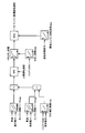
- FIG. 3 is a diagram showing a calculation flow of the target rotation speed of the engine 20 in this embodiment.
- the engine rotation speed base map is used to identify the rotation speed of the base corresponding to the vehicle speed and the required electric power.
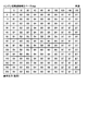
- FIG. 5 is a diagram showing an engine rotation speed base map in this embodiment.
- the column heading value is the vehicle speed
- the row heading value is the required output (required power, that is, the load on the engine 20)
- the cell value is the rotation speed. Even if the required power changes, if the vehicle speed is the same, the rotation speed is set to be constant. Further, from 0 km/h to 60 km/h, the rotational speed is set to be constant even if the vehicle speed changes, and at 80 km/h or more, the rotational speed changes gradually as the vehicle speed increases. It is set to increase.
- the corrected rotation speed corresponding to the vehicle speed and the required electric power is specified using the engine rotation speed correction base map.
- the corrected rotation speed is the rotation speed used to correct the rotation speed of the base.
- FIG. 6 is a diagram showing an engine rotation speed correction base map in this embodiment.
- the column heading value is the vehicle speed
- the row heading value is the required output (required power, that is, the load on the engine 20)
- the cell value is the rotation speed. Even if the required power increases, if the vehicle speed is the same, the corrected rotation speed is set to be constant. Further, at 0 km/h to 100 km/h, a value is set that gradually increases from A1 rpm to A4 rpm when simply added to the value of the engine rotation speed base map. At 120 km/h or higher, B7 rpm, which is smaller than B6 rpm, is set.
- B5 rpm is specified as the corrected rotation speed.
- the corrected rotation speed B5 rpm is simply added to the rotation speed A1 rpm specified in the engine rotation speed base map at this time to obtain A1+B5 rpm.
- the correction coefficient corresponding to the SOC of the battery 10 is specified using the SOC correction coefficient map.
- This correction coefficient is a correction coefficient for increasing the correction rotation speed when the SOC decreases.
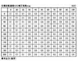
- FIG. 7 is a diagram showing a target rotation speed SOC correction coefficient map in this embodiment.
- column heading values are SOC
- row heading values are required output (required power, that is, load on engine 20)
- cell values are correction coefficients. Even if the required power increases, if the SOC is the same, the correction coefficient is set to be constant. Further, when the SOC is 30 or less, the correction coefficient is set to be constant even if the SOC changes. When the SOC is 45 or more, the correction coefficient is set to be constant even if the SOC changes. For example, when the SOC is 40% and the required power is 100 kW, C2 is specified as the correction coefficient.
- calculation for multiplying the corrected rotational speed specified by the engine rotational speed correction base map of FIG. 6 by the correction coefficient specified by the target rotational speed SOC correction coefficient map of FIG. is added to the rotation speed specified in the engine rotation speed base map of FIG. 5 (a calculation indicated by a symbol “+” in the drawing).
- the target rotation speed SOC correction coefficient map specifies the correction rotation speed B5 rpm specified by the engine rotation speed correction base map.
- the product of the corrected correction coefficient C2 and the rotation speed A1 rpm specified in the engine rotation speed base map is A1+B5 ⁇ C2 rpm.
- the calculation (the calculation indicated by the symbol "MIN" in the figure) that regulates the upper limit rotation speed is performed.
- the result of the operation indicated by the symbol “+” is J1 rpm, and when the upper limit rotation speed is set to 1.5 ⁇ J1, the upper limit rotation speed is not exceeded. The result remains J1 rpm.
- the smoothing coefficient map is used to specify the smoothing coefficient corresponding to the SOC of the battery 10.
- This smoothing coefficient is a coefficient for changing the rotation speed when the SOC has a margin.
- FIG. 8 is a diagram showing a smoothing coefficient map in this embodiment.
- the column heading value is SOC
- the cell value is the moderating coefficient.
- the smoothing coefficient is set such that the larger the SOC, the greater the degree of smoothing. If the SOC is 30 or less, the smoothing coefficient is set to D1 which indicates that there is no smoothing. When the SOC is 50 or more, the smoothing coefficient is set to be constant (D3) even if the SOC changes. For example, when the SOC is 40%, D2 is specified as the smoothing coefficient.
- the rotation speed obtained by the calculation for restricting the upper limit rotation speed is subjected to the smoothing process by using the smoothing coefficient specified in the smoothing coefficient map shown in FIG.
- a primary smoothing process is performed, but a secondary smoothing process or a higher-order smoothing process may be performed.
- the first-order smoothing process for example, the difference obtained by subtracting the previous rotation speed from the rotation speed obtained by the calculation indicated by the symbol “MIN” is divided by the smoothing coefficient to obtain the previous rotation speed. Perform addition operation. Note that, as shown in FIG. 2, the calculation of FIG. 3 is executed at every predetermined control cycle, but “previous” is the time before the predetermined control cycle.
- the minimum engine speed map is used to identify the minimum engine speed corresponding to the minimum generated power.
- the minimum generated power is the power obtained by subtracting the power that can be output from the battery 10 from the required power.
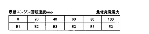
- FIG. 9 is a diagram showing a minimum engine rotation speed map in this embodiment.
- the value of the column heading is the minimum generated power
- the value of the cell is the minimum engine speed.
- a calculation for restricting the lower limit rotation speed (calculation indicated by the symbol “MAX” in the figure) is performed.
- the result of this calculation is the target rotation speed of the engine 20.
- the rotation speed obtained by the calculation of the first-order smoothing process is 1.5 ⁇ E2 rpm and the minimum engine rotation speed is E2 rpm, it does not fall below the minimum engine rotation speed, so it is indicated by the symbol “MAX”.
- the target rotation speed of the engine 20, which is the result of the calculation is set to 1.5 ⁇ E2 rpm.
- FIG. 4 is a diagram showing a calculation flow of the target output of the engine 20 in this embodiment. Referring to FIG. 4, first, the output of engine 20 of the base corresponding to the engine target rotation speed and the required power is specified using the engine target output base map.
- FIG. 10 is a diagram showing an engine target output base map in this embodiment.
- the value of the column heading is the target rotation speed
- the value of the row heading is the required output (required power, that is, the load on the engine 20)
- the cell value is the output of the engine 20. is there.
- the output of the engine 20 is set to be constant (constant load) if the rotational speed is the same even if the required power changes.
- the required power is 50 kW or more, the output of the engine 20 increases as the required power increases (power generation priority).
- the correction coefficient corresponding to the engine target rotation speed and the SOC of the battery 10 is specified using the target output SOC correction coefficient map.
- This correction coefficient is a correction coefficient for increasing the output of the engine 20 when the SOC decreases.
- FIG. 11 is a diagram showing a target output SOC correction coefficient map in this embodiment.
- the column heading value is the SOC of engine 20, and the cell value is the correction coefficient.
- the SOC correction coefficient is set to G1
- the SOC is 60 or more
- the correction coefficient is set to G2.
- the correction coefficient is G1.
- the calculation of multiplying the output of the engine 20 specified by the engine target output base map of FIG. 10 by the correction coefficient specified by the target output SOC correction coefficient map of FIG. 11 (the symbol “x” in the drawing) ). For example, if the output of the engine 20 is J3 kW and the correction coefficient is G1, then J3 ⁇ G1 kW.
- the smoothing coefficient map is used to identify the smoothing coefficient corresponding to the engine speed and the SOC of the battery 10.
- the smoothing coefficient is a coefficient for reducing the output of the engine 20 when the SOC has a margin.
- FIG. 12 is a diagram showing a smoothing coefficient map in this embodiment.
- the value of the column heading is SOC
- the value of the cell is a smoothing coefficient.
- the smoothing coefficient is set such that the larger the SOC, the greater the degree of smoothing. If the SOC is 30 or less, the smoothing coefficient is set to H1 indicating that the smoothing is not performed at all. When the SOC is 40 or more, the smoothing coefficient is set to be constant even if the SOC changes. For example, when the SOC is 40%, H3 is specified as the smoothing coefficient.
- the output of the engine 20 obtained by the operation indicated by the symbol “ ⁇ ” is subjected to the smoothing processing using the smoothing coefficient specified in the smoothing coefficient map of FIG.
- a primary smoothing process is performed, but a secondary smoothing process or a higher-order smoothing process may be performed.
- the first-order smoothing process for example, the difference obtained by subtracting the previous output of the engine 20 from the output of the engine 20 obtained by the calculation indicated by the symbol “ ⁇ ” above is divided by the smoothing coefficient, The output of the engine 20 is calculated. Note that, as shown in FIG. 2, the calculation of FIG. 4 is executed for each predetermined control cycle, but the “previous time” is the time before the predetermined control cycle.
- the minimum generated power is the power obtained by subtracting the power that can be output from the battery 10 from the required power.
- the result of this calculation is the target output of the engine 20.
- the output obtained by the calculation of the first-order smoothing process is J5+20 kW and the minimum generated power is J5 kW, it does not fall below the minimum generated power, so the result of the calculation indicated by the symbol "MAX" is the engine 20.
- the target output of is set to J5+20 kW.
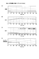
- FIG. 13 is a diagram showing a first example of the control result in this embodiment.
- the broken line in FIG. 13(C) As shown by, the required output for driving the vehicle 100 has a constant value.
- FIGS. 13(B) to 13(D) from the time 0 to 40 seconds when the SOC of the battery 10 has not reached the charge completion SOC, it is calculated by the flow shown in FIGS. 3 and 4.
- the engine 20 is controlled so that the target rotation speed and the target output are obtained.
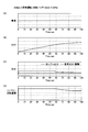
- FIG. 14 is a diagram showing a second example of the control result in this embodiment.
- FIGS. 14B to 14D from the time 0 to 85 seconds when the SOC of the battery 10 has not reached the charge completion SOC, the calculation is performed by the flow shown in FIGS. 3 and 4.
- the engine 20 is controlled so that the target rotation speed and the target output are obtained.
- FIG. 15 is a diagram showing a third example of the control result in this embodiment.
- the broken line in FIG. 15(C) As shown by, the required output for driving the vehicle 100 has a constant value.
- FIGS. 15B to 15D since the charging completion SOC is not reached in the entire period shown in the figure, the flow shown in FIGS. 3 and 4 is performed in the entire period shown in the figure.
- the engine 20 is controlled so that the calculated target rotation speed and target output are obtained.
- the engine 20 is controlled based on the power generation priority output indicated by the cell value of the row heading rotation speed 2395 rpm and the row heading required output of 50 kW or more in FIG. To be done.
- the correction coefficient changes as shown in the target rotation speed SOC correction coefficient map of FIG. 7, so the target rotation speed and target output of engine 20 are reduced.
- FIG. 15C and FIG. 15D the graph is drawn such that the rotation speed and the output sharply increase from time 0 seconds, but actually, the graphs are illustrated in FIGS. 3 and 4. By the smoothing process indicated by, the rotation speed and the output are controlled to be gently increased.
- FIG. 16 is a diagram showing a first example of the comprehensive control result in this embodiment.
- the vehicle 100 is driven so as to change the vehicle speed in mode driving (RDE (Real Driving Emission, actual road test)) as shown in FIG. 16(A).
- RDE Real Driving Emission, actual road test
- the SOC can be controlled within the range from the charge start SOC to the charge end SOC, as shown in FIG.
- the rotation speed and output of the engine 20 can be zero for many periods.
- the solid line shows the output of engine 20
- the broken line shows the output of MG 31 for driving vehicle 100.
- FIG. 17 is a diagram showing a second example of the comprehensive control result in this embodiment.
- this is an example in which vehicle 100 is run such that the vehicle speed changes at full-open acceleration from 0 km/h to 140 km/h as shown in FIG. 17(A).
- the SOC is significantly reduced because the vehicle runs at full load during the period from time 0 seconds to time 25 seconds during acceleration.
- both MG31 and MG32 are motor generators.
- the MG 31 is not limited to this, and may be a generator.
- MG 32 may be an electric motor.
- the change rate of the target rotation speed of the engine 20 and the change rate of the target output torque are limited.
- the engine 20 is controlled using the map of FIG.
- the present invention is not limited to this, and if at least one of the change rate of the target rotation speed of the engine 20 and the change rate of the target output torque is limited, the control may be performed by another method.
- at least one of the target rotation speed change rate and the target output torque change rate is not limited to be smaller than a predetermined change rate, and the target rotation speed change rate and the target output torque change rate are not limited.
- At least one of the ratios may be limited to 0 (that is, at least one of the target rotation speed and the target output torque may be kept constant).
- the exhaust treatment device is configured to be a combination of the DPF 71 and the NSR catalyst 72.
- the exhaust processing device is not limited to this, and may have any structure.
- the DeNOx catalyst that reduces NOx contained in the exhaust gas may be an SCR catalyst that uses a reducing agent (for example, urea water, HC) instead of the NSR catalyst 72.
- the above-described embodiment can be regarded as a disclosure of a hybrid system including the engine 20, the MG 31, the MG 32, the battery 10, and the control device (EG-ECU 52, HV-ECU 51, PCU 11). Further, it can be understood as disclosure of such a hybrid system control device or disclosure of a hybrid system control method. In addition, it can be regarded as a disclosure of a vehicle 100 including such a hybrid system.
- the hybrid system includes an engine 20, an MG 32 that uses the power output from the engine 20 to generate power, a battery 10 that charges the power generated by the MG 32, and a battery 10.
- An MG 31 for driving vehicle 100 driven using at least one of the discharge power and the power generated by MG 32, and a control device (EG-ECU 52, HV-ECU 51, PCU 11) are provided.
- the control device performs control so as to limit at least one of the change rate of the target rotation speed of the engine 20 and the change rate of the target output torque.
- black smoke is discharged more than the legal regulation value. It is designed in advance so as to be restricted to be smaller than at least one of the rate of change of nitrogen oxides and the rate of emission of nitrogen oxides higher than legally regulated values.
- the control device controls the engine 20 according to such calculation. It should be noted that a voluntary regulation value may be used instead of the legal regulation value.
- the hybrid system at least one of the change rate of the target rotation speed and the change rate of the target output torque of the engine 20 in which at least one of black smoke and nitrogen oxides emitted from the engine 20 is emitted in excess of the legally regulated value.
- the engine 20 is controlled so that at least one of the target rotation speed change rate and the target output torque change rate of the engine 20 is smaller than the one.
- control device changes the target rotation speed of the engine 20 and the target output torque. Control at least one of the rates.
- the hybrid system at least one of the change rate of the target rotation speed and the change rate of the target output torque of the engine 20 in which at least one of black smoke and nitrogen oxides emitted from the engine 20 is emitted in excess of the legally regulated value.
- the engine 20 is controlled so that at least one of the target rotation speed change rate and the target output torque change rate of the engine 20 is smaller than the one.
- the control device compares the case where the SOC of the battery 10 is higher than the charge start SOC in the calculation shown in the flows of FIGS. Thus, at least one of the rate of change of the target rotation speed of the engine 20 and the rate of change of the target output torque is made small.
- the control maps shown in FIGS. 5 to 12 are based on the engine rotation speed base map of FIG. 5 in which the rotation speed can be specified from the required power to the MG 32 and the vehicle speed, and the required power to the MG 32 and the target rotation speed.
- the engine target output base map of FIG. 10 which can specify target output torque is included.
- the engine target output base map of the control map generates more power than the control that limits at least one of the target rotation speed change rate and the target output torque change rate of the engine 20. Including areas that prioritize. In addition, giving priority to power generation means that the required power is generated by the output of the engine 20 without particularly limiting the change rate of the target rotation speed and the change rate of the target output torque.
- power generation can be prioritized over suppression of at least one of the change rate of the target rotation speed and the change rate of the target output torque of the engine 20.
Landscapes
- Engineering & Computer Science (AREA)
- Mechanical Engineering (AREA)
- Chemical & Material Sciences (AREA)
- Combustion & Propulsion (AREA)
- Transportation (AREA)
- Automation & Control Theory (AREA)
- Power Engineering (AREA)
- Sustainable Development (AREA)
- Sustainable Energy (AREA)
- Life Sciences & Earth Sciences (AREA)
- General Engineering & Computer Science (AREA)
- Electric Propulsion And Braking For Vehicles (AREA)
- Hybrid Electric Vehicles (AREA)
- Control Of Vehicle Engines Or Engines For Specific Uses (AREA)
Abstract
ハイブリッドシステムは、エンジン(20)と、エンジン(20)から出力される動力を利用して発電を行なうMG(32)と、MG(32)による発電電力を充電するバッテリ(10)と、バッテリ(10)の放電電力およびMG(32)による発電電力のうちの少なくとも一方の電力を用いて駆動される車両(100)の駆動用のMG(31)と、制御装置(52、51、11)とを備える。制御装置(52、51、11)は、エンジン(20)の目標回転速度の変化率および目標出力トルクの変化率のうちの少なくとも一方を制限するよう制御する(S103~S105)。
Description
この開示は、ハイブリッドシステム、ハイブリッドシステムの制御装置、および、ハイブリッドシステムの制御方法に関し、特に、内燃機関の動力を利用して発電した電力を用いて電動機で駆動される車両に搭載されるハイブリッドシステム、ハイブリッドシステムの制御装置、および、ハイブリッドシステムの制御方法に関する。
従来、ハイブリッド方式の車両において、加速中のエンジンの負荷を一定に保つように制御するものがあった(たとえば、特許文献1参照)。特許文献1の車両においては、加速初期は、エンジンの余った出力をモータジェネレータにより回生しながら走行することでバッテリのSOC(State Of Charge)が上昇する。加速後半は、このバッテリの電力を用いてモータジェネレータにより力行して、エンジンの不足する出力をアシストしながら走行する。このように制御すれば、スモークの発生を抑制することができる。
しかし、特許文献1の車両においては、エンジンの負荷を一定に保つ直前に、負荷を急激に上昇させる必要がある。このため、過給遅れによりスモーク(黒煙)およびNOx(窒素酸化物)の排出量が悪化してしまう。また、エンジンの負荷を一定に保っているときに、車両を急加速する場合は、そのためにエンジンの回転速度も急に上昇させる必要があるので、同様に、過給遅れによりスモークおよびNOxの排出量が悪化してしまう。
この開示は、上述の問題を解決するためになされたものであり、その目的は、黒煙および窒素酸化物の排出量を低減することが可能なハイブリッドシステム、ハイブリッドシステムの制御装置、および、ハイブリッドシステムの制御方法を提供することである。
この開示によるハイブリッドシステムは、内燃機関と、内燃機関から出力される動力を利用して発電を行なう発電機と、発電機による発電電力を充電する蓄電装置と、蓄電装置の放電電力および発電機による発電電力のうちの少なくとも一方の電力を用いて駆動される車両駆動用の電動機と、内燃機関の目標回転速度の変化率および目標出力トルクの変化率のうちの少なくとも一方を制限するよう制御する制御装置とを備える。
好ましくは、制御装置は、内燃機関の目標回転速度の変化率および目標出力トルクの変化率のうちの少なくとも一方が、黒煙が第1所定量よりも多く排出される変化率および窒素酸化物が第2所定量よりも多く排出される変化率の少なくとも一方よりも小さくなるように制限する。
さらに好ましくは、制御装置は、内燃機関の目標回転速度の変化率および目標出力トルクの変化率のうちの少なくとも一方を、予め定められた制御マップを用いて制御する。
さらに好ましくは、制御装置は、蓄電装置のSOCが所定値よりも高い場合は低い場合と比較して内燃機関の目標回転速度の変化率および目標出力トルクの変化率のうちの少なくとも一方が小さくなるようにする。
さらに好ましくは、制御マップは、発電機への要求電力および車速から回転速度を特定可能なマップ、および、発電機への要求電力および目標回転速度から目標出力トルクを特定可能なマップを含む。
さらに好ましくは、制御マップは、内燃機関の目標回転速度の変化率および目標出力トルクの変化率のうちの少なくとも一方を制限する制御よりも発電を優先する領域を含む。
この開示の他の局面によるハイブリッドシステムの制御装置は、内燃機関と、内燃機関から出力される動力を利用して発電を行なう発電機と、発電機による発電電力を充電する蓄電装置と、蓄電装置の放電電力および発電機による発電電力のうちの少なくとも一方の電力を用いて駆動される車両駆動用の電動機とを備えるハイブリッドシステムを制御する制御装置である。制御装置は、内燃機関の目標回転速度の変化率および目標出力トルクの変化率のうちの少なくとも一方を制限するよう制御する。
この開示のさらに他の局面によるハイブリッドシステムの制御方法は、内燃機関と、内燃機関から出力される動力を利用して発電を行なう発電機と、発電機による発電電力を充電する蓄電装置と、蓄電装置の放電電力および発電機による発電電力のうちの少なくとも一方の電力を用いて駆動される車両駆動用の電動機とを備えるハイブリッドシステムを制御する制御装置による制御方法である。制御方法は、制御装置が、内燃機関の目標回転速度の変化率および目標出力トルクの変化率のうちの少なくとも一方を制限するよう制御するステップを含む。
この開示に従えば、ハイブリッドシステムにおいて内燃機関の目標回転速度の変化率および目標出力トルクの変化率の少なくとも一方が制限される。その結果、黒煙および窒素酸化物の排出量を低減することが可能なハイブリッドシステム、ハイブリッドシステムの制御装置、および、ハイブリッドシステムの制御方法を提供することができる。
以下、図面を参照しつつ、本開示の実施の形態について説明する。以下の説明では、同一の部品には同一の符号が付されている。それらの名称および機能も同じである。したがってそれらについての詳細な説明は繰返されない。
図1は、この実施の形態における車両100の概略構成を示す図である。図1を参照して、車両100は、バッテリ10と、電力制御ユニット(以下、「PCU(Power Control Unit)」と称する)11と、エンジン20と、モータジェネレータ(以下、「MG(Motor Generator)」と称する)31と、MG32と、駆動輪40とを含む。また、車両100は、後述するHV-ECU51やEG-ECU52など、各種電子制御装置(ECU:Electronic Control Unit)をさらに含む。本実施の形態に係るバッテリ10は、本開示に係る「蓄電装置」の一例に相当する。
エンジン20は、燃料(ガソリンや軽油等)を燃焼させたときに生じる燃焼エネルギをピストンやクランクシャフトなどの運動子の運動エネルギに変換することによって動力を出力する内燃機関である。MG31およびMG32は、電気エネルギを力学的エネルギに変換したり、力学的エネルギを電気エネルギに変換したりする電力機器である。本実施の形態では、エンジン20としてディーゼルエンジンを採用し、MG31およびMG32として、ロータに永久磁石が埋設された三相交流同期式の電動発電機を採用する。エンジン20は、吸排気系にターボチャージャ(たとえば、可変ノズルターボ)を備えていてもよい。
本実施の形態に係る車両100は、シリーズハイブリッド車両である。車両100において、MG31(走行用モータ)は、電動機として動作することによって駆動輪40を駆動し、MG32は、エンジン20により駆動されることによって発電を行なう。MG31を駆動するための動力源は、MG32で発電される電力、およびバッテリ10に蓄えられる電力である。より具体的には、エンジン20の回転軸21とMG32の回転軸22とは、互いにギア23を介して機械的に連結され、エンジン20の回転軸21の回転に伴ってMG32の回転軸22も回転して、MG32が発電する。一方、MG31の回転軸41は、回転軸21,22とは機械的に連結されておらず、動力伝達ギア43を介して駆動軸42と機械的に連結されている。MG31の回転軸41に出力されるトルク(駆動力)は動力伝達ギア43を介して駆動軸42に伝達され、MG31の駆動力によって駆動軸42が回転する。そして、駆動軸42が回転することによって、駆動軸42の両端に設けられた駆動輪40が回転する。
MG31は、車両100の加速時において電動機として動作し、車両100の駆動輪40を駆動する。他方、車両100の制動時や下り斜面での加速度低減時においては、MG31は発電機として動作して回生発電を行なう。MG31が発電した電力は、PCU11を介してバッテリ10に供給される。
MG32は、エンジン20から出力される動力を利用して発電(エンジン発電)を行なうように構成される。MG32において生成されたエンジン発電電力は、MG32からMG31に供給されたり、MG32からPCU11を介してバッテリ10に供給されたりする。
PCU11は、MG31およびMG32に対応して設けられる2つのインバータと、各インバータに供給される直流電圧をバッテリ10の電圧以上(たとえば、600V)に昇圧する昇圧コンバータとを含んで構成される。PCU11は、HV-ECU51からの制御信号に従ってバッテリ10とMG31およびMG32との間で電力変換を実行する。PCU11は、MG31およびMG32の状態をそれぞれ別々に制御可能に構成されている。
バッテリ10は、再充電可能な直流電源である。バッテリ10の定格電圧は、たとえば300V~450Vである。バッテリ10は、たとえば二次電池(再充電可能な電池)を含んで構成される。二次電池としては、たとえばリチウムイオン電池を採用できる。バッテリ10は、直列および/または並列に接続された複数の二次電池(たとえば、リチウムイオン電池)から構成される組電池を含んでいてもよい。なお、バッテリ10を構成する二次電池は、リチウムイオン電池に限られず、他の二次電池(たとえば、ニッケル水素電池)を採用してもよい。電解液式二次電池を採用してもよいし、全固体式二次電池を採用してもよい。また、バッテリ10としては、大容量のキャパシタなども採用可能である。
バッテリ10に対しては、バッテリ10の状態を監視する監視ユニット61が設けられている。監視ユニット61は、バッテリ10の状態(温度、電流、電圧等)を検出する各種センサを含む。HV-ECU51は、監視ユニット61の出力に基づいてバッテリ10の状態(SOC等)を検出するように構成される。SOC(State Of Charge)は、蓄電残量を示し、たとえば、満充電状態の蓄電量に対する現在の蓄電量の割合を0~100%で表わしたものである。SOCの測定方法としては、たとえば、電流値積算(クーロンカウント)による手法、または開放電圧(OCV:Open Circuit Voltage)の推定による手法など、種々の公知の手法を採用できる。
また、エンジン20に対しては、エンジン20の状態を監視する監視ユニット62が設けられている。監視ユニット62は、エンジン20の状態(冷却水温、吸気量、回転速度等)を検出する各種センサを含む。HV-ECU51およびEG-ECU52は、監視ユニット62の出力に基づいてエンジン20の状態を検出するように構成される。
また、MG31およびMG32に対しては、それぞれMG31およびMG32の状態を監視する監視ユニット63,64が設けられている。監視ユニット63,64は、MG31およびMG32の状態(温度、回転速度等)を検出する各種センサを含む。HV-ECU51は、監視ユニット63,64の出力に基づいてMG31およびMG32の状態を検出するように構成される。
車両100に含まれる各ECU(HV-ECU51、EG-ECU52)は、演算装置としてのCPU(Central Processing Unit)と、記憶装置と、各種信号を入出力するための入出力ポートと(いずれも図示せず)を含んで構成される。記憶装置は、作業用メモリとしてのRAM(Random Access Memory)と、保存用ストレージ(ROM(Read Only Memory)、書き換え可能な不揮発性メモリ等)とを含む。各ECUは、入力ポートに接続された各種機器(センサ等)から信号を受信し、受信した信号に基づいて出力ポートに接続された各種機器を制御する。記憶装置に記憶されているプログラムをCPUが実行することで、各種制御が実行される。ただし、各ECUが行なう制御については、ソフトウェアによる処理に限られず、専用のハードウェア(電子回路)で処理することも可能である。本実施の形態に係るHV-ECU51およびEG-ECU52は、本開示に係る「制御装置」として機能する。
HV-ECU51は、エンジン20に対する出力要求値と、MG31およびMG32に対する出力要求値(たとえば、トルク要求値)とを算出する。そして、HV-ECU51は、エンジン20に対する出力要求値をEG-ECU52へ送信するとともに、MG31およびMG32に対する出力要求値に基づいて、MG31およびMG32に対する電力の供給(ひいては、MG31およびMG32の出力トルク)を制御する。HV-ECU51は、PCU11等を制御することにより、MG31およびMG32へ供給される電力の大きさ(振幅)および周波数等を制御することができる。また、HV-ECU51は、PCU11等を制御することにより、バッテリ10の充放電制御を行なう。
HV-ECU51の入力ポートに接続された各種機器は、監視ユニット61,63,64に含まれる各種センサのほかに、アクセル開度センサ65、および、車速センサ66をさらに含む。
アクセル開度センサ65は、車両100のアクセルペダル(図示せず)の踏み込み量をアクセル開度として検出し、その検出結果(アクセル開度を示す信号)をHV-ECU51へ出力する。HV-ECU51は、アクセルペダルの踏み込み量が大きくなるほど、MG31の駆動力を大きくする。
また、車速センサ66は、車両100の速度を検出し、その検出結果(車速を示す信号)をHV-ECU51へ出力する。
EG-ECU52は、HV-ECU51からエンジン20に対する出力要求値を受信し、その出力要求値に対応する運動エネルギがエンジン20で発生するように、エンジン20の運転制御(燃料噴射制御、点火制御、吸入空気量調節制御等)を行なう。エンジン20の駆動によってエンジン発電が実行され、エンジン発電が行なわれていないときは、エンジン20は停止している。エンジン20が駆動されることによって、MG32においてエンジン発電電力が生成される。また、EG-ECU52は、監視ユニット62に含まれる各種センサの検出値を受信し、各検出値をHV-ECU51へ送信する。
車両100の走行は、MG31が駆動輪40を駆動することによって行なわれる。HV-ECU51は、車両100の走行中に、バッテリ10のSOCが充電開始SOC以下になった場合に、エンジン発電電力によるバッテリ10の充電を開始し、バッテリ10のSOCが充電完了SOC以上になった場合に、その充電を停止させる。
バッテリ10のSOCが充電開始SOC以下であり、エンジン発電電力によるバッテリ10の充電を実行する場合、HV-ECU51は、発電に適した所定条件でエンジン20を駆動することをEG-ECU52に要求し、この要求に従ってEG-ECU52がエンジン20を制御することによって、車両100の走行で消費される電力よりも大きなエンジン発電電力がMG32で生成される。また、HV-ECU51は、PCU11等を制御して、生成されたエンジン発電電力をバッテリ10に供給する。これにより、エンジン発電電力によってバッテリ10が充電され、バッテリ10のSOCが高くなる。
バッテリ10のSOCが充電完了SOC以上となった場合には、HV-ECU51が、EG-ECU52に指示してエンジン20を停止させるとともに、PCU11等を制御してバッテリ10への電力の供給を停止させる。
このように、車両100の走行中においては、バッテリ10のSOCが充電開始SOC以下になるたびにエンジン20が起動し、エンジン発電電力によるバッテリ10の充電が実行される。これにより、バッテリ10のSOCは、充電開始SOC以上かつ充電完了SOC以下の範囲内に概ね維持される。
また、本実施の形態においては、車両100は、エンジン20の排気を処理する装置として、DPF(Diesel Particulate Filter)71と、NSR(NOx Storage Reduction)触媒72とを含む。エンジン20、DPF71およびNSR触媒72の間は、それぞれ排気管で接続される。
エンジン20およびDPF71の間の排気管には、排気温センサ81と、A/Fセンサ82とが設けられる。排気温センサ81は、エンジン20からの排気の温度を検出し、その検出結果(排気温を示す信号)をEG-ECU52へ出力する。A/Fセンサ82は、エンジン20からの排気を分析して空燃比を検出し、その検出結果(空燃比を示す信号)をEG-ECU52へ出力する。
DPF71は、エンジン20の排気通路を流れる排気に含まれる粒子状物質(PM:Particulate Matter)を捕集するフィルタである。捕集されたPMは、DPF71の内部に堆積する。このため、定期的にDPF71の内部を高温にして、PMを燃焼させて除去することで、DPF71を再生する。
NSR触媒72は、吸蔵還元型NOx触媒であって、たとえばアルミナ(Al2O3)を担体とし、この担体上に例えばカリウム(K)、ナトリウム(Na)、リチウム(Li)、セシウムCsのようなアルカリ金属、バリウムBa、カルシウムCaのようなアルカリ土類、ランタン(La)、イットリウム(Y)のような希土類と、白金Ptのような貴金属とが担持されることによって構成される。
このNSR触媒72は、排気中に多量の酸素が存在している状態においてはNOxを吸収し、排気中の酸素濃度が低く、かつ還元成分(例えば燃料の未燃成分(HC))が多量に存在している状態においてはNOxをNO2もしくはNOに還元して放出する。NO2やNOとして放出されたNOxは、排気中のHCやCOと速やかに反応することによってさらに還元されてN2となる。ちなみにHCやCOは、NO2やNOを還元することで、自身は酸化されてH2OやCO2となる。すなわち、NSR触媒72に導入される排気中の酸素濃度やHC成分を適宜調整すれば、排気中のHC、CO、NOxを浄化することができることになる。
NSR触媒72の下流の排気管には、NOxセンサ83が設けられる。NOxセンサ83は、NSR触媒72から出てきた排気に含まれるNOxの量を検出し、その検出結果(NOxの量を示す信号)をEG-ECU52へ出力する。
このようなエンジン20の動力を利用して発電した電力を用いてMG31で駆動される車両100に搭載されるハイブリッドシステムにおいて、加速中のエンジン20の負荷を一定に保つように制御する場合に、加速初期は、エンジン20の余った出力をMG32により回生しながら走行することでバッテリ10のSOC(State Of Charge)が上昇する。加速後半は、このバッテリ10の電力を用いてMG31により力行して、エンジン20の不足する出力をアシストしながら走行する。このように制御すれば、スモークの発生を抑制することができる。
しかし、エンジン20の負荷を一定に保つ直前に、負荷を急激に上昇させる必要がある。このため、過給遅れによりスモークおよびNOxの排出量が悪化してしまう。また、エンジン20の負荷を一定に保っているときに、車両100を急加速する場合は、そのためにエンジン20の回転速度も急に上昇させる必要があるので、同様に、過給遅れによりスモークおよびNOxの排出量が悪化してしまう。
そこで、この実施の形態においては、HV-ECU51およびEG-ECU52は、エンジン20の目標回転速度および目標出力トルクの変化率を制限するよう制御する。これにより、スモークおよびNOxの排出量を低減することができる。
図2は、この実施の形態におけるエンジン制御処理の流れを示すフローチャートである。このエンジン制御処理は、メイン処理から所定の制御周期ごとに呼出されて、EG-ECU52によって実行される。図2を参照して、EG-ECU52は、車速、SOC、アクセル開度等に従い、MG32による発電の要求電力を算出する(ステップ(以下「S」と記載する)101)。この要求電力は、アクセル開度等にしたがって車両100を駆動させるために必要な電力である。バッテリ10のSOCが充電完了SOCを上回った場合には、要求電力は0とされる。その結果、エンジン20が停止される。バッテリ10のSOCが充電開始SOCを下回った場合には、要求電力が算出され、発電要求が出される。
次に、EG-ECU52は、発電要求が有る、つまり、要求電力が0でないか否かを判断する(S102)。発電要求が無い(S102でNO)と判断した場合、EG-ECU52は、実行する処理をこの処理の呼出元に戻す。
一方、発電要求が有る(S102でYES)と判断した場合、EG-ECU52は、車速および要求電力に従い、エンジン20の目標回転速度を算出する(S103)。目標回転速度の算出については、後述の図3で説明する。次に、EG-ECU52は、目標回転速度および車速に従い、エンジン20の目標出力を算出する(S104)。目標出力の算出については、後述の図4で説明する。EG-ECU52は、算出した目標回転速度および目標出力となるようにエンジン20を制御し(S105)、EG-ECU52は、実行する処理をこの処理の呼出元の処理に戻す。
このエンジン20の回転速度および出力の制御は、たとえば、MG32で回転速度を制御することにより実行される。具体的には、回転速度を高い目標回転速度とする場合、まず、MG32の発電量を下げるようPCU11を制御する。すると、要求電力に対して発電量が下回るため、発電量を上げるためMG32の回転速度、すなわち、エンジン20の回転速度を上げるよう制御される。次に、MG32の発電量を上げるようPCU11を制御する。この時点で、当初の発電量よりも高い発電量となるように制御される。すると、要求電力に対して発電量が上回るため、発電量を下げるためMG32の回転速度、すなわち、エンジン20の回転速度を下げるよう制御される。この時点で、当初の回転速度よりも高い回転速度となるように制御される。さらに、MG32の発電量を下げるようPCU11を制御する。すると、要求電力に対して発電量が下回るため、発電量を上げるためMG32の回転速度、すなわち、エンジン20の回転速度を上げるよう制御される。この時点で、目標回転速度となるように制御される。なお、エンジン20の回転速度および出力の制御は、他の方法で実行されるようにしてもよい。
図3は、この実施の形態におけるエンジン20の目標回転速度の算出フローを示す図である。図3を参照して、まず、エンジン回転速度ベースマップを用いて車速および要求電力に対応するベースの回転速度を特定する。
図5は、この実施の形態におけるエンジン回転速度ベースマップを示す図である。図5を参照して、このマップにおいては、列見出しの値が車速、行見出しの値が要求出力(要求電力、つまり、エンジン20に掛かる負荷)、セルの値は回転速度である。要求電力が変化しても、車速が同一であれば、回転速度は一定となるように設定されている。また、0km/hから60km/hにおいては、車速が変化しても、回転速度は一定となるように設定されており、80km/h以上においては、車速の増加に従って回転速度の変化が緩やかに増加するように設定されている。なお、図5において、A1<A2<A3<A4である。たとえば、車速が60km/hであり、要求電力が100kWである場合、回転速度としてA1rpmが特定される。
また、車速が75km/hであり、要求電力が150kWである場合、75km/hの直下の列見出しの60kmと150kWの直下,直上の行見出しの140kW,160kWとに対応するセルの値であるA1rpm、および、75km/hの直上の列見出しの80kmと150kWの直下,直上の列見出しの140kW,160kWとに対応するセルの値であるA2rpmに基づいて、補間により、回転速度として、(A2-A1)×(75-60)/(80-60)+A1=(3×A2+A1)/4rpmが特定される。
図3に戻って、エンジン回転速度補正ベースマップを用いて車速および要求電力に対応する補正回転速度を特定する。補正回転速度は、ベースの回転速度を補正するために用いられる回転速度である。
図6は、この実施の形態におけるエンジン回転速度補正ベースマップを示す図である。図6を参照して、このマップにおいては、列見出しの値は車速、行見出しの値は要求出力(要求電力、つまり、エンジン20に掛かる負荷)、セルの値は回転速度である。要求電力が増加しても、車速が同一であれば、補正回転速度は一定となるように設定されている。また、0km/hから100km/hにおいて、エンジン回転速度ベースマップの値に単純に加算した場合にA1rpmからA4rpmまで徐々に増加する値が設定されている。120km/h以上において、B6rpmよりも小さいB7rpmが設定されている。たとえば、車速が60km/hであり、要求電力が100kWである場合、補正回転速度としてB5rpmが特定される。このときのエンジン回転速度ベースマップで特定された回転速度A1rpmに、この補正回転速度B5rpmを単純に加算すると、A1+B5rpmとなる。
図3に戻って、SOC補正係数マップを用いてバッテリ10のSOCに対応する補正係数を特定する。この補正係数は、SOCが下がったら、補正回転速度を増加させるための補正係数である。
図7は、この実施の形態における目標回転速度SOC補正係数マップを示す図である。図7を参照して、このマップにおいては、列見出しの値はSOC、行見出しの値は要求出力(要求電力、つまり、エンジン20に掛かる負荷)、セルの値は補正係数である。要求電力が増加しても、SOCが同一であれば、補正係数は一定となるように設定されている。また、SOCが30以下においては、SOCが変化しても、補正係数は一定となるように設定されている。SOCが45以上においては、SOCが変化しても、補正係数は一定となるように設定されている。たとえば、SOCが40%であり、要求電力が100kWである場合、補正係数としてC2が特定される。
図3に戻って、図6のエンジン回転速度補正ベースマップで特定された補正回転速度に、図7の目標回転速度SOC補正係数マップで特定された補正係数を掛ける演算(図中「×」の記号で示す演算)をしたものを、図5のエンジン回転速度ベースマップで特定された回転速度に加算する演算(図中「+」の記号で示す演算)をする。たとえば、車速が60km/hであり、要求電力が100kWであり、SOCが40%である場合、エンジン回転速度補正ベースマップで特定された補正回転速度B5rpmに、目標回転速度SOC補正係数マップで特定された補正係数C2をかけたものを、エンジン回転速度ベースマップで特定された回転速度A1rpmに加算すると、A1+B5×C2rpmとなる。
次に、上限回転速度を超える場合に上限回転速度に規制する演算(図中「MIN」の記号で示す演算)をする。たとえば、上述の「+」の記号で示す演算の結果は、J1rpmであり、上限回転速度を1.5×J1とする場合、上限回転速度を超えないので、「MIN」の記号で示す演算の結果は、J1rpmのままとなる。
次に、なまし係数マップを用いてバッテリ10のSOCに対応するなまし係数を特定する。このなまし係数は、SOCに余裕がある場合に、回転速度の変化をなますための係数である。
図8は、この実施の形態におけるなまし係数マップを示す図である。図8を参照して、このマップにおいては、列見出しの値はSOC、セルの値はなまし係数である。SOCが大きいほどなましの度合いが大きくなるようななまし係数が設定されている。SOCが30以下であれば、なまし係数がまったくなまさないことを示すD1となるように設定されている。SOCが50以上においては、SOCが変化しても、なまし係数は一定(D3)となるように設定されている。たとえば、SOCが40%である場合、なまし係数としてD2が特定される。
図3に戻って、上限回転速度を規制する演算で得られた回転速度に、図8で示したなまし係数マップで特定されたなまし係数を用いてなまし処理を施す演算をする。ここでは、なまし処理として、1次なまし処理を施すが、2次なまし処理やさらに高次のなまし処理を施すようにしてもよい。1次なまし処理においては、たとえば、上述の「MIN」の記号で示す演算で得られた回転速度から前回の回転速度を減算した差をなまし係数で割ったものを、前回の回転速度に加算する演算をする。なお、図2で示したように、所定の制御周期ごとに図3の演算が実行されるが、「前回」とは、所定の制御周期前の回のことである。たとえば、なまし係数がSOC40%に対応するD2であり、「MIN」の記号で示す演算で得られた回転速度がJ2rpmであり、前回の回転速度がJ2×9/10rpmである場合、1次なまし処理の演算によって、(J2-J2×9/10)/D2+J2×9/10=(1+9×D2)×J2/(10×D2)rpmが得られる。このように、なまし係数がD1よりも大きくなるにしたがって、前回の回転速度からの変化が小さくなる。
次に、最低エンジン回転速度マップを用いて最低発電電力に対応する最低エンジン回転速度を特定する。最低発電電力は、要求電力から、バッテリ10の出力可能な電力を減算した電力である。
図9は、この実施の形態における最低エンジン回転速度マップを示す図である。図9を参照して、このマップにおいては、列見出しの値は最低発電電力、セルの値は最低エンジン回転速度である。要求電力に対してバッテリ10からの供給で足りない電力は、最低限、発電する必要がある。このため、最低発電電力が大きいほど、最低エンジン回転速度が大きくなるように設定されている。最低発電電力が40kW以上であれば、最低エンジン回転速度がE3rpmとなるように設定されている。最低発電電力が0kWであれば、最低エンジン回転速度がE1(=0)となるように設定されている。たとえば、最低発電電力が20kWである場合、最低エンジン回転速度としてE2rpmが特定される。
図3に戻って、1次なまし処理の演算の後、最低エンジン回転速度を下回る場合に、下限回転速度を規制する演算(図中「MAX」の記号で示す演算)をする。この演算の結果が、エンジン20の目標回転速度とされる。たとえば、1次なまし処理の演算で得られた回転速度が1.5×E2rpmであり、最低エンジン回転速度がE2rpmである場合、最低エンジン回転速度を下回らないので、「MAX」の記号で示す演算の結果であるエンジン20の目標回転速度は、1.5×E2rpmとされる。
図4は、この実施の形態におけるエンジン20の目標出力の算出フローを示す図である。図4を参照して、まず、エンジン目標出力ベースマップを用いてエンジン目標回転速度および要求電力に対応するベースのエンジン20の出力を特定する。
図10は、この実施の形態におけるエンジン目標出力ベースマップを示す図である。図10を参照して、このマップにおいては、列見出しの値が目標回転速度、行見出しの値が要求出力(要求電力、つまり、エンジン20に掛かる負荷)、セルの値はエンジン20の出力である。2390rpm以下では、要求電力が変化しても、回転速度が同一であれば、エンジン20の出力が一定となるように設定されている(負荷一定)。2395rpmでは、要求電力が50kW以上であれば、要求電力が大きくなるほど、エンジン20の出力が大きくなるように設定されている(発電優先)。たとえば、エンジン20の目標回転速度が1840rpmであり、要求電力が100kWである場合、1840rpmの直下の列見出しの1600rpmと行見出しの100kWとに対応するセルの値であるF4kW、および、1840rpmの直上の列見出しの2000rpmと行見出しの100kWとに対応するセルの値であるF5kWに基づいて、補間により、(1840-1600)×(F5-F4)/(2000-1600)+F4=(3×F5+2×F4)/5kWが特定される。
図4に戻って、また、目標出力SOC補正係数マップ用いてエンジン目標回転速度およびバッテリ10のSOCに対応する補正係数を特定する。この補正係数は、SOCが下がったら、エンジン20の出力を増加させるための補正係数である。
図11は、この実施の形態における目標出力SOC補正係数マップを示す図である。図11を参照して、このマップにおいては、列見出しの値がエンジン20のSOC、セルの値は補正係数である。SOCが50以下では、SOC補正係数がG1、SOCが60以上では、補正係数がG2となるように設定されている。たとえば、SOCが40%である場合、補正係数はG1である。
図4に戻って、図10のエンジン目標出力ベースマップで特定されたエンジン20の出力に、図11の目標出力SOC補正係数マップで特定された補正係数を掛ける演算(図中「×」の記号で示す演算)をする。たとえば、エンジン20の出力がJ3kWで、補正係数がG1である場合、J3×G1kWとなる。
次に、なまし係数マップを用いてエンジン回転速度およびバッテリ10のSOCに対応するなまし係数を特定する。このなまし係数は、SOCに余裕がある場合に、エンジン20の出力の変化をなますための係数である。
図12は、この実施の形態におけるなまし係数マップを示す図である。図12を参照して、このマップにおいては、列見出しの値はSOC、セルの値はなまし係数である。SOCが大きいほどなましの度合いが大きくなるようななまし係数が設定されている。SOCが30以下であれば、なまし係数がまったくなまさないことを示すH1となるように設定されている。SOCが40以上においては、SOCが変化しても、なまし係数は一定となるように設定されている。たとえば、SOCが40%である場合、なまし係数としてH3が特定される。
図4に戻って、「×」の記号で示す演算で得られたエンジン20の出力に、図12のなまし係数マップで特定されたなまし係数を用いてなまし処理を施す演算をする。ここでは、なまし処理として、1次なまし処理を施すが、2次なまし処理やさらに高次のなまし処理を施すようにしてもよい。1次なまし処理においては、たとえば、上述の「×」の記号で示す演算で得られたエンジン20の出力から前回のエンジン20の出力を減算した差をなまし係数で割ったものを、前回のエンジン20の出力に加算する演算をする。なお、図2で示したように、所定の制御周期ごとに図4の演算が実行されるが、「前回」とは、所定の制御周期前の回のことである。たとえば、なまし係数がSOC40%に対応するH3であり、「×」の記号で示す演算で得られたエンジン20の出力がJ4kWであり、前回の回転速度がJ4×9/10kWである場合、1次なまし処理の演算によって、(J4-J4×9/10)/H3+J4×9/10=(1+9×H3)×J4/(10×H3)kWが得られる。このように、なまし係数がH1よりも大きくなるにしたがって、前回のエンジン20の出力からの変化が小さくなる。
1次なまし処理の演算の後、最低発電電力を下回る場合に、エンジン20の下限出力を規制する演算(図中「MAX」の記号で示す演算)をする。最低発電電力は、要求電力から、バッテリ10の出力可能な電力を減算した電力である。この演算の結果が、エンジン20の目標出力とされる。たとえば、1次なまし処理の演算で得られた出力がJ5+20kWであり、最低発電電力がJ5kWである場合、最低発電電力を下回らないので、「MAX」の記号で示す演算の結果であるエンジン20の目標出力は、J5+20kWとされる。
図13は、この実施の形態における制御結果の第1の例を示す図である。図13を参照して、図13(A)で示すように、バッテリ10の初期SOC=50%の状態から40km/hの定常運転で車両100を走行させた場合、図13(C)の破線で示すように、車両100の駆動のための要求出力は一定値となる。また、図13(B)から図13(D)で示すように、バッテリ10のSOCが充電完了SOCに達していない時刻0から40秒までは、図3および図4で示したフローで算出された目標回転速度および目標出力となるように、エンジン20が制御される。時刻40秒以降は、バッテリ10のSOCが充電完了SOCに達したため、エンジン20が停止させられる。なお、図13(C)および図13(D)においては、時刻0秒から急激に回転速度および出力が上昇しているようにグラフが描かれているが、実際には、図3および図4で示したなまし処理により回転速度および出力の上昇はなだらかとなるように制御される。
図14は、この実施の形態における制御結果の第2の例を示す図である。図14を参照して、図14(A)で示すように、バッテリ10の初期SOC=50%の状態から100km/hの定常運転で車両100を走行させた場合、図14(C)の破線で示すように、車両100の駆動のための要求出力は一定値となる。また、図14(B)から図14(D)で示すように、バッテリ10のSOCが充電完了SOCに達していない時刻0から85秒までは、図3および図4で示したフローで算出された目標回転速度および目標出力となるように、エンジン20が制御される。時刻85秒以降は、バッテリ10のSOCが充電完了SOCに達したため、エンジン20が停止させられる。なお、図14(C)および図14(D)においては、時刻0秒から急激に回転速度および出力が上昇しているようにグラフが描かれているが、実際には、図3および図4で示したなまし処理により回転速度および出力の上昇はなだらかとなるように制御される。
図15は、この実施の形態における制御結果の第3の例を示す図である。図15を参照して、図14(A)で示すように、バッテリ10の初期SOC=20%の状態から100km/hの定常運転で車両100を走行させた場合、図15(C)の破線で示すように、車両100の駆動のための要求出力は一定値となる。また、図15(B)から図15(D)で示すように、図で示す全期間で充電完了SOCに達していないので、図で示す全期間で、図3および図4で示したフローで算出された目標回転速度および目標出力となるように、エンジン20が制御される。SOC=40%に達する時刻58秒付近までは、図10の列見出しの回転速度2395rpmの、行見出しの要求出力50kW以上のセルの値で示される発電優先の出力に基づいて、エンジン20が制御される。時刻58秒付近でSOC=40%に達すると、図7の目標回転速度SOC補正係数マップで示したように補正係数が変わるので、エンジン20の目標回転速度および目標出力が下げられる。なお、図15(C)および図15(D)においては、時刻0秒から急激に回転速度および出力が上昇しているようにグラフが描かれているが、実際には、図3および図4で示したなまし処理により回転速度および出力の上昇はなだらかとなるように制御される。
図16は、この実施の形態における総合的な制御結果の第1の例を示す図である。図16を参照して、図16(A)で示すような、モード走行(RDE(Real Driving Emission、実路走行試験))の車速変化となるように車両100を走行させた場合の例である。この場合は、図16(B)で示すように、SOCは、充電開始SOCから充電終了SOCの範囲内で制御可能である。
図16(C)および図16(D)で示すように、時刻0から1800秒までの低負荷走行においては、エンジン20の回転速度および出力を0とできる期間が多い。なお、図16(C)において、実線がエンジン20の出力を示し、破線が車両100の駆動用のMG31の出力を示す。
また、図16(C)および図16(D)で示すように、時刻3900秒から6400秒までの高負荷走行においては、図3および図4で示したなまし処理によって、エンジン20の回転速度および出力の変化率を抑制した発電が行われる。
図17は、この実施の形態における総合的な制御結果の第2の例を示す図である。図17を参照して、図17(A)で示すような、0km/hから140km/hまでの全開加速での車速変化となるように車両100を走行させた場合の例である。この場合は、図17(B)で示すように、加速中である時刻0秒から25秒までの期間は全負荷走行となるため、SOCは大きく低下する。
図17(C)および図17(D)で示すように、時刻0秒から25秒までの加速中は、ほぼ、駆動用のMG31が最高出力で動かされる。これに伴い、図17(B)で示すように、バッテリ10のSOCが急激に低下するので、エンジン20の出力および回転速度が、なまし処理無しで発電優先で制御される。その後、図17(B)で示すように、時刻75秒付近でバッテリ10のSOCが充電開始SOCに達すると、エンジン20の出力が低下させられる。
[変形例]
(1) 前述した実施の形態においては、MG31およびMG32は、いずれも電動発電機であることとした。しかし、これに限定されず、MG31は、発電機であってもよい。MG32は、電動機であってもよい。
(1) 前述した実施の形態においては、MG31およびMG32は、いずれも電動発電機であることとした。しかし、これに限定されず、MG31は、発電機であってもよい。MG32は、電動機であってもよい。
(2) 前述した実施の形態においては、図3および図4のフローにしたがい、エンジン20の目標回転速度の変化率および目標出力トルクの変化率を制限するように予め定められた、図5から図12のマップを用いて、エンジン20を制御するようにした。しかし、これに限定されず、エンジン20の目標回転速度の変化率および目標出力トルクの変化率の少なくとも一方を制限するのであれば、他の方法で制御するようにしてもよい。また、目標回転速度の変化率および目標出力トルクの変化率の少なくとも一方を、所定の変化率よりも小さくなるように制限することに限定されず、目標回転速度の変化率および目標出力トルクの変化率の少なくとも一方を0に制限する(すなわち、目標回転速度および目標出力トルクの少なくとも一方を一定にする)ようにしてもよい。
(3) 前述した実施の形態においては、排気処理装置の構成がDPF71とNSR触媒72との組合せであることとした。しかし、これに限定されず、排気処理装置の構成はどのような構成であってもよい。たとえば、排気に含まれるNOxを還元するDeNOx触媒が、NSR触媒72でなく、還元剤(たとえば、尿素水、HC)を利用するSCR触媒であってもよい。
(4) 前述した実施の形態を、エンジン20とMG31とMG32とバッテリ10と制御装置(EG-ECU52、HV-ECU51、PCU11)とを含むハイブリッドシステムの開示として捉えることができる。また、このようなハイブリッドシステムの制御装置の開示、または、ハイブリッドシステムの制御方法の開示として捉えることができる。また、このようなハイブリッドシステムを備える車両100の開示として捉えることができる。
[効果]
(1) 図1で示したように、ハイブリッドシステムは、エンジン20と、エンジン20から出力される動力を利用して発電を行なうMG32と、MG32による発電電力を充電するバッテリ10と、バッテリ10の放電電力およびMG32による発電電力のうちの少なくとも一方の電力を用いて駆動される車両100の駆動用のMG31と、制御装置(EG-ECU52、HV-ECU51、PCU11)とを備える。図2から図12で示したように、制御装置は、エンジン20の目標回転速度の変化率および目標出力トルクの変化率のうちの少なくとも一方を制限するよう制御する。
(1) 図1で示したように、ハイブリッドシステムは、エンジン20と、エンジン20から出力される動力を利用して発電を行なうMG32と、MG32による発電電力を充電するバッテリ10と、バッテリ10の放電電力およびMG32による発電電力のうちの少なくとも一方の電力を用いて駆動される車両100の駆動用のMG31と、制御装置(EG-ECU52、HV-ECU51、PCU11)とを備える。図2から図12で示したように、制御装置は、エンジン20の目標回転速度の変化率および目標出力トルクの変化率のうちの少なくとも一方を制限するよう制御する。
これにより、ハイブリッドシステムにおいて、エンジン20の目標回転速度の変化率および目標出力トルクの変化率のうちの少なくとも一方が制限される。その結果、黒煙および窒素酸化物の排出量を低減することができる。
(2) 図3および図4のフローで示される演算は、エンジン20の目標回転速度の変化率および目標出力トルクの変化率のうちの少なくとも一方が、黒煙が法規制値よりも多く排出される変化率および窒素酸化物が法規制値よりも多く排出される変化率の少なくとも一方よりも小さくなるように制限するように予め設計される。制御装置は、このような演算に従いエンジン20を制御する。なお、法規制値でなく、自主規制値であってもよい。
これにより、ハイブリッドシステムにおいて、エンジン20から排出される黒煙および窒素酸化物の少なくとも一方が法規制値よりも多く排出されるエンジン20の目標回転速度の変化率および目標出力トルクの変化率の少なくとも一方よりも、エンジン20の目標回転速度の変化率および目標出力トルクの変化率の少なくとも一方が小さくなるようにエンジン20が制御される。
(3) 図3および図4のフローで示される演算で用いられる図5から図12で示した制御マップを用いて、制御装置は、エンジン20の目標回転速度の変化率および目標出力トルクの変化率のうちの少なくとも一方を制御する。
これにより、ハイブリッドシステムにおいて、エンジン20から排出される黒煙および窒素酸化物の少なくとも一方が法規制値よりも多く排出されるエンジン20の目標回転速度の変化率および目標出力トルクの変化率の少なくとも一方よりも、エンジン20の目標回転速度の変化率および目標出力トルクの変化率の少なくとも一方が小さくなるようにエンジン20が制御される。
(4) 図16および図17で示したように、制御装置は、前述の図3および図4のフローで示される演算においてバッテリ10のSOCが充電開始SOCよりも高い場合は低い場合と比較してエンジン20の目標回転速度の変化率および目標出力トルクの変化率のうちの少なくとも一方が小さくなるようにする。
(5) 図5から図12で示した制御マップは、MG32への要求電力および車速から回転速度を特定可能な図5のエンジン回転速度ベースマップ、および、MG32への要求電力および目標回転速度から目標出力トルクを特定可能な図10のエンジン目標出力ベースマップを含む。
(6) 図10で示したように、制御マップのうちエンジン目標出力ベースマップは、エンジン20の目標回転速度の変化率および目標出力トルクの変化率のうちの少なくとも一方を制限する制御よりも発電を優先する領域を含む。なお、発電を優先するとは、目標回転速度の変化率および目標出力トルクの変化率を特に制限せず、要求電力をエンジン20の出力により発電することである。
これにより、バッテリ10のSOCが充電開始SOCよりも低い場合に、エンジン20の目標回転速度の変化率および目標出力トルクの変化率の少なくとも一方の抑制よりも、発電を優先させることができる。
今回開示された各実施の形態は、適宜組合わせて実施することも予定されている。そして、今回開示された実施の形態は、すべての点で例示であって制限的なものではないと考えられるべきである。本開示の範囲は、上記した実施の形態の説明ではなくて特許請求の範囲によって示され、特許請求の範囲と均等の意味および範囲内でのすべての変更が含まれることが意図される。
10 バッテリ
11 PCU
20 エンジン
21,22,41 回転軸
23 ギア
31,32 MG
40 駆動輪
42 駆動軸
43 動力伝達ギア
51 HV-ECU
52 EG-ECU
61,62,63,64 監視ユニット
65 アクセル開度センサ
66 車速センサ
71 DPF
72 NSR触媒
81 排気温センサ
82 A/Fセンサ
83 NOxセンサ
100 車両
11 PCU
20 エンジン
21,22,41 回転軸
23 ギア
31,32 MG
40 駆動輪
42 駆動軸
43 動力伝達ギア
51 HV-ECU
52 EG-ECU
61,62,63,64 監視ユニット
65 アクセル開度センサ
66 車速センサ
71 DPF
72 NSR触媒
81 排気温センサ
82 A/Fセンサ
83 NOxセンサ
100 車両
Claims (8)
- 内燃機関と、
前記内燃機関から出力される動力を利用して発電を行なう発電機と、
前記発電機による発電電力を充電する蓄電装置と、
前記蓄電装置の放電電力および前記発電機による発電電力のうちの少なくとも一方の電力を用いて駆動される車両駆動用の電動機と、
前記内燃機関の目標回転速度の変化率および目標出力トルクの変化率のうちの少なくとも一方を制限するよう制御する制御装置とを備える、ハイブリッドシステム。 - 前記制御装置は、前記内燃機関の目標回転速度の変化率および目標出力トルクの変化率のうちの少なくとも一方が、黒煙が第1所定量よりも多く排出される変化率および窒素酸化物が第2所定量よりも多く排出される変化率の少なくとも一方よりも小さくなるように制限する、請求項1に記載のハイブリッドシステム。
- 前記制御装置は、前記内燃機関の目標回転速度の変化率および目標出力トルクの変化率のうちの少なくとも一方を、予め定められた制御マップを用いて制御する、請求項2に記載のハイブリッドシステム。
- 前記制御装置は、前記蓄電装置のSOCが所定値よりも高い場合は低い場合と比較して前記内燃機関の目標回転速度の変化率および目標出力トルクの変化率のうちの少なくとも一方が小さくなるようにする、請求項2または請求項3に記載のハイブリッドシステム。
- 前記制御マップは、前記発電機への要求電力および車速から回転速度を特定可能なマップ、および、前記発電機への前記要求電力および目標回転速度から目標出力トルクを特定可能なマップを含む、請求項3に記載のハイブリッドシステム。
- 前記制御マップは、前記内燃機関の目標回転速度の変化率および目標出力トルクの変化率のうちの少なくとも一方を制限する制御よりも発電を優先する領域を含む、請求項3に記載のハイブリッドシステム。
- 内燃機関と、前記内燃機関から出力される動力を利用して発電を行なう発電機と、前記発電機による発電電力を充電する蓄電装置と、前記蓄電装置の放電電力および前記発電機による発電電力のうちの少なくとも一方の電力を用いて駆動される車両駆動用の電動機とを備えるハイブリッドシステムを制御する制御装置であって、
前記内燃機関の目標回転速度の変化率および目標出力トルクの変化率のうちの少なくとも一方を制限するよう制御する、ハイブリッドシステムの制御装置。 - 内燃機関と、前記内燃機関から出力される動力を利用して発電を行なう発電機と、前記発電機による発電電力を充電する蓄電装置と、前記蓄電装置の放電電力および前記発電機による発電電力のうちの少なくとも一方の電力を用いて駆動される車両駆動用の電動機とを備えるハイブリッドシステムを制御する制御装置による制御方法であって、
前記制御装置が、前記内燃機関の目標回転速度の変化率および目標出力トルクの変化率のうちの少なくとも一方を制限するよう制御するステップを含む、ハイブリッドシステムの制御方法。
Priority Applications (1)
| Application Number | Priority Date | Filing Date | Title |
|---|---|---|---|
| CN201980089171.7A CN113302101B (zh) | 2019-01-17 | 2019-12-19 | 混合动力系统、混合动力系统的控制装置和混合动力系统的控制方法 |
Applications Claiming Priority (2)
| Application Number | Priority Date | Filing Date | Title |
|---|---|---|---|
| JP2019005901A JP7213445B2 (ja) | 2019-01-17 | 2019-01-17 | ハイブリッドシステム、ハイブリッドシステムの制御装置、および、ハイブリッドシステムの制御方法 |
| JP2019-005901 | 2019-01-17 |
Publications (1)
| Publication Number | Publication Date |
|---|---|
| WO2020149100A1 true WO2020149100A1 (ja) | 2020-07-23 |
Family
ID=71614331
Family Applications (1)
| Application Number | Title | Priority Date | Filing Date |
|---|---|---|---|
| PCT/JP2019/049948 Ceased WO2020149100A1 (ja) | 2019-01-17 | 2019-12-19 | ハイブリッドシステム、ハイブリッドシステムの制御装置、および、ハイブリッドシステムの制御方法 |
Country Status (4)
| Country | Link |
|---|---|
| JP (1) | JP7213445B2 (ja) |
| CN (1) | CN113302101B (ja) |
| TW (1) | TWI734345B (ja) |
| WO (1) | WO2020149100A1 (ja) |
Cited By (2)
| Publication number | Priority date | Publication date | Assignee | Title |
|---|---|---|---|---|
| CN114852045A (zh) * | 2021-02-04 | 2022-08-05 | 本田技研工业株式会社 | 控制装置及车辆 |
| CN116888024A (zh) * | 2021-02-19 | 2023-10-13 | 日产自动车株式会社 | 串联式混合动力车辆的控制方法及控制装置 |
Families Citing this family (1)
| Publication number | Priority date | Publication date | Assignee | Title |
|---|---|---|---|---|
| TWI839208B (zh) * | 2023-05-08 | 2024-04-11 | 亞福儲能股份有限公司 | 複合電能系統及其能源管理最佳化方法 |
Citations (6)
| Publication number | Priority date | Publication date | Assignee | Title |
|---|---|---|---|---|
| JPH07336809A (ja) * | 1994-06-06 | 1995-12-22 | Toyota Motor Corp | シリーズハイブリッド車の制御方法 |
| JPH0837702A (ja) * | 1994-07-25 | 1996-02-06 | Toyota Motor Corp | シリーズハイブリッド車の発電制御方法 |
| JPH11346402A (ja) * | 1998-06-02 | 1999-12-14 | Mitsubishi Motors Corp | ハイブリッド車両 |
| JP2000125414A (ja) * | 1998-10-15 | 2000-04-28 | Nissan Motor Co Ltd | ハイブリッド車両の制御装置 |
| JP2008512301A (ja) * | 2004-09-15 | 2008-04-24 | ロベルト・ボッシュ・ゲゼルシャフト・ミト・ベシュレンクテル・ハフツング | 自動車の駆動装置の運転方法及びこの方法を実施するための装置 |
| JP2017213986A (ja) * | 2016-05-31 | 2017-12-07 | スズキ株式会社 | ハイブリッド車両の制御装置 |
Family Cites Families (1)
| Publication number | Priority date | Publication date | Assignee | Title |
|---|---|---|---|---|
| MX356879B (es) * | 2013-09-26 | 2018-06-19 | Nissan Motor | Dispositivo de control para vehículo híibrido. |
-
2019
- 2019-01-17 JP JP2019005901A patent/JP7213445B2/ja active Active
- 2019-12-19 CN CN201980089171.7A patent/CN113302101B/zh active Active
- 2019-12-19 WO PCT/JP2019/049948 patent/WO2020149100A1/ja not_active Ceased
-
2020
- 2020-01-15 TW TW109101306A patent/TWI734345B/zh active
Patent Citations (6)
| Publication number | Priority date | Publication date | Assignee | Title |
|---|---|---|---|---|
| JPH07336809A (ja) * | 1994-06-06 | 1995-12-22 | Toyota Motor Corp | シリーズハイブリッド車の制御方法 |
| JPH0837702A (ja) * | 1994-07-25 | 1996-02-06 | Toyota Motor Corp | シリーズハイブリッド車の発電制御方法 |
| JPH11346402A (ja) * | 1998-06-02 | 1999-12-14 | Mitsubishi Motors Corp | ハイブリッド車両 |
| JP2000125414A (ja) * | 1998-10-15 | 2000-04-28 | Nissan Motor Co Ltd | ハイブリッド車両の制御装置 |
| JP2008512301A (ja) * | 2004-09-15 | 2008-04-24 | ロベルト・ボッシュ・ゲゼルシャフト・ミト・ベシュレンクテル・ハフツング | 自動車の駆動装置の運転方法及びこの方法を実施するための装置 |
| JP2017213986A (ja) * | 2016-05-31 | 2017-12-07 | スズキ株式会社 | ハイブリッド車両の制御装置 |
Cited By (4)
| Publication number | Priority date | Publication date | Assignee | Title |
|---|---|---|---|---|
| CN114852045A (zh) * | 2021-02-04 | 2022-08-05 | 本田技研工业株式会社 | 控制装置及车辆 |
| CN116888024A (zh) * | 2021-02-19 | 2023-10-13 | 日产自动车株式会社 | 串联式混合动力车辆的控制方法及控制装置 |
| US12077149B2 (en) | 2021-02-19 | 2024-09-03 | Nissan Motor Co., Ltd. | Control method for series hybrid vehicle and control device for series hybrid vehicle |
| CN116888024B (zh) * | 2021-02-19 | 2025-04-01 | 日产自动车株式会社 | 串联式混合动力车辆的控制方法及控制装置 |
Also Published As
| Publication number | Publication date |
|---|---|
| JP2020114688A (ja) | 2020-07-30 |
| TWI734345B (zh) | 2021-07-21 |
| CN113302101A (zh) | 2021-08-24 |
| TW202031537A (zh) | 2020-09-01 |
| JP7213445B2 (ja) | 2023-01-27 |
| CN113302101B (zh) | 2024-02-27 |
Similar Documents
| Publication | Publication Date | Title |
|---|---|---|
| US10400694B2 (en) | Hybrid vehicle | |
| US10465623B2 (en) | Hybrid vehicle | |
| US9821795B2 (en) | Hybrid vehicle and control method for hybrid vehicle | |
| JP6137310B2 (ja) | ハイブリッド車両の制御装置 | |
| JP4615037B2 (ja) | ハイブリッド自動車およびその制御方法 | |
| JP6241438B2 (ja) | ハイブリッド車両の制御装置 | |
| JP7213445B2 (ja) | ハイブリッドシステム、ハイブリッドシステムの制御装置、および、ハイブリッドシステムの制御方法 | |
| CN111749768A (zh) | 混合动力车辆 | |
| JP4086010B2 (ja) | 動力出力装置およびこれを搭載する自動車並びに動力出力装置の制御方法 | |
| US20200307547A1 (en) | Hybrid vehicle | |
| US20200139956A1 (en) | Hybrid vehicle | |
| JP4059287B2 (ja) | 動力出力装置およびその制御方法並びにこれを搭載する自動車 | |
| CN111794853A (zh) | 混合动力车辆 | |
| JP2015058786A (ja) | ハイブリッド車両の制御装置 | |
| JP2020069950A (ja) | ハイブリッド自動車 | |
| WO2020080063A1 (ja) | ハイブリッドシステム、ハイブリッドシステムの制御装置、および、ハイブリッドシステムの制御方法 | |
| JP2015223907A (ja) | ハイブリッド車両の制御装置 | |
| JP7800499B2 (ja) | 制御装置 | |
| WO2020085003A1 (ja) | ハイブリッドシステム、ハイブリッドシステムの制御装置、および、ハイブリッドシステムの制御方法 | |
| JP4086076B2 (ja) | 動力出力装置およびその制御方法並びにこれを搭載する自動車 | |
| JP7768158B2 (ja) | エンジンの制御装置 | |
| JP2004320841A (ja) | 内燃機関の排気浄化システム | |
| JP2025088591A (ja) | ハイブリッド車両の制御方法 | |
| JP2020111165A (ja) | ハイブリッド自動車 | |
| JP2021161936A (ja) | 車両の制御装置 |
Legal Events
| Date | Code | Title | Description |
|---|---|---|---|
| 121 | Ep: the epo has been informed by wipo that ep was designated in this application |
Ref document number: 19910131 Country of ref document: EP Kind code of ref document: A1 |
|
| NENP | Non-entry into the national phase |
Ref country code: DE |
|
| 122 | Ep: pct application non-entry in european phase |
Ref document number: 19910131 Country of ref document: EP Kind code of ref document: A1 |