WO2020149091A1 - 電子制御装置 - Google Patents
電子制御装置 Download PDFInfo
- Publication number
- WO2020149091A1 WO2020149091A1 PCT/JP2019/049748 JP2019049748W WO2020149091A1 WO 2020149091 A1 WO2020149091 A1 WO 2020149091A1 JP 2019049748 W JP2019049748 W JP 2019049748W WO 2020149091 A1 WO2020149091 A1 WO 2020149091A1
- Authority
- WO
- WIPO (PCT)
- Prior art keywords
- electronic control
- wall
- control device
- filter
- height
- Prior art date
- Legal status (The legal status is an assumption and is not a legal conclusion. Google has not performed a legal analysis and makes no representation as to the accuracy of the status listed.)
- Ceased
Links
Images












Classifications
-
- B—PERFORMING OPERATIONS; TRANSPORTING
- B60—VEHICLES IN GENERAL
- B60R—VEHICLES, VEHICLE FITTINGS, OR VEHICLE PARTS, NOT OTHERWISE PROVIDED FOR
- B60R16/00—Electric or fluid circuits specially adapted for vehicles and not otherwise provided for; Arrangement of elements of electric or fluid circuits specially adapted for vehicles and not otherwise provided for
- B60R16/02—Electric or fluid circuits specially adapted for vehicles and not otherwise provided for; Arrangement of elements of electric or fluid circuits specially adapted for vehicles and not otherwise provided for electric constitutive elements
- B60R16/023—Electric or fluid circuits specially adapted for vehicles and not otherwise provided for; Arrangement of elements of electric or fluid circuits specially adapted for vehicles and not otherwise provided for electric constitutive elements for transmission of signals between vehicle parts or subsystems
- B60R16/0239—Electronic boxes
-
- H—ELECTRICITY
- H05—ELECTRIC TECHNIQUES NOT OTHERWISE PROVIDED FOR
- H05K—PRINTED CIRCUITS; CASINGS OR CONSTRUCTIONAL DETAILS OF ELECTRIC APPARATUS; MANUFACTURE OF ASSEMBLAGES OF ELECTRICAL COMPONENTS
- H05K5/00—Casings, cabinets or drawers for electric apparatus
- H05K5/0026—Casings, cabinets or drawers for electric apparatus provided with connectors and printed circuit boards [PCB], e.g. automotive electronic control units
- H05K5/0047—Casings, cabinets or drawers for electric apparatus provided with connectors and printed circuit boards [PCB], e.g. automotive electronic control units having a two-part housing enclosing a PCB
- H05K5/0056—Casings, cabinets or drawers for electric apparatus provided with connectors and printed circuit boards [PCB], e.g. automotive electronic control units having a two-part housing enclosing a PCB characterized by features for protecting electronic components against vibration and moisture, e.g. potting, holders for relatively large capacitors
-
- H—ELECTRICITY
- H05—ELECTRIC TECHNIQUES NOT OTHERWISE PROVIDED FOR
- H05K—PRINTED CIRCUITS; CASINGS OR CONSTRUCTIONAL DETAILS OF ELECTRIC APPARATUS; MANUFACTURE OF ASSEMBLAGES OF ELECTRICAL COMPONENTS
- H05K5/00—Casings, cabinets or drawers for electric apparatus
- H05K5/02—Details
- H05K5/0213—Venting apertures; Constructional details thereof
- H05K5/0216—Venting plugs comprising semi-permeable membranes
-
- H—ELECTRICITY
- H05—ELECTRIC TECHNIQUES NOT OTHERWISE PROVIDED FOR
- H05K—PRINTED CIRCUITS; CASINGS OR CONSTRUCTIONAL DETAILS OF ELECTRIC APPARATUS; MANUFACTURE OF ASSEMBLAGES OF ELECTRICAL COMPONENTS
- H05K5/00—Casings, cabinets or drawers for electric apparatus
- H05K5/04—Metal casings
Definitions
- the present invention relates to an electronic control device.
- the electronic control unit When installing an electronic control unit in an environment where water is splashed, such as in an engine room, it is necessary to make the electronic control unit waterproof and dustproof, but if the inside of the electronic control unit is completely airtight, it will be electronically controlled due to temperature changes. There is a concern that the casing or the seal part due to the waterproof adhesive may be damaged due to the pressure difference generated inside/outside the device. Further, the electronic control device serves as a pump, which draws water into the electronic control from the harness connected to the connector, which may cause a short circuit between the electronic components. Therefore, it is necessary to arrange a "respiratory filter" to keep the pressure inside/outside the electronic controller uniform.
- the breathing filter generally has a structure in which an O-ring is placed in a housing with a filter membrane that adjusts the pressure difference and the O-ring is crushed between the housing to which it is attached and the inside of the electronic control unit is waterproof and dustproof. Is known to be.
- Patent Document 1 it is generally known that a wall is provided around the breathing filter to prevent liquid from splashing on the breathing filter, as in Patent Document 1, for example.
- the liquid which is a subject of Patent Document 1 is high-pressure water used when washing a vehicle, etc., and in Patent Document 1, the purpose is to prevent the high-pressure water from directly hitting the breathing filter and entering the electronic control unit.
- salt water spattering from the road may be scattered in a straight line or in a mist form, and also penetrates into a narrow gap between the respiratory filter and the wall. Moreover, the narrower the distance between the respiratory filter and the wall, the less drainage of salt water. As a result, when salt water pools occur, electrons in the metal housing move and corrosion occurs. Therefore, in the structure of Patent Document 1, there is still room for studying improvement of salt damage resistance.
- the purpose of the present invention is to realize an electronic control device that can be used even in an on-board environment where salt damage is severe.
- the electronic control device of the present invention is designed so that the minimum distance between the wall and the respiratory filter is 3 mm or more.
- FIG. 1 is a perspective view of an electronic control device according to a first embodiment of the present invention. Exploded view of the electronic control unit according to the first embodiment of the present invention Front view of the electronic control device according to the first embodiment of the present invention Front enlarged view of the electronic control unit according to the first embodiment of the present invention Sectional drawing of the electronic control unit by the 1st Embodiment of this invention. Sectional enlarged view of the electronic control unit according to the first embodiment of the present invention.
- Contact angle and surface tension when salt water is dropped on the cover 2 is a perspective view of an electronic control device according to a second embodiment of the present invention.
- FIG. 3 is a perspective view of an electronic control device according to a third embodiment of the present invention.
- FIG. Sectional drawing of the electronic control unit by the 3rd Embodiment of this invention.
- Front view of an electronic control device according to a fourth embodiment of the present invention Sectional drawing of the electronic control unit by the 4th Embodiment of this invention.
- Enlarged sectional view of the electronic control unit according to the fourth embodiment of the present invention when traveling on a downhill Front view of an electronic control unit according to a fifth embodiment of the present invention Sectional drawing of the electronic control unit by the 5th Embodiment of this invention.
- Front view of an electronic control unit according to a sixth embodiment of the present invention Sectional drawing of the electronic control unit by the 6th Embodiment of this invention.
- Front view of an electronic control unit according to a seventh embodiment of the present invention Sectional drawing of the electronic control unit by the 7th Embodiment of this invention.
- Sectional enlarged view of an electronic control unit according to a seventh embodiment of the present invention Front view of an electronic control device according to an eighth embodiment of the present invention Sectional drawing of the electronic control unit by the 8th Embodiment of this invention. Sectional enlarged view of an electronic control unit according to an eighth embodiment of the present invention. Front view of an electronic control device according to a ninth embodiment of the present invention Sectional drawing of the electronic control unit by the 9th Embodiment of this invention. Sectional enlarged view of an electronic control unit according to a ninth embodiment of the present invention. Front view of the electronic control unit according to the tenth embodiment of the present invention Sectional drawing of the electronic control unit by the 10th Embodiment of this invention. Sectional enlarged view of an electronic control unit according to a tenth embodiment of the present invention.
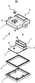
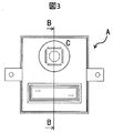
- the electronic control unit A in the present embodiment is mounted on, for example, an automobile and used for controlling an engine, a transmission, a brake, or the like. As shown in FIGS. 1 and 2, the electronic control unit A electrically connects a circuit board 5 on which an electronic component 4 is mounted, an electric circuit mounted on the circuit board 5 and formed on the circuit board 5 to an external device. A connector 3 that is electrically connected, a base 7 that houses the circuit board 5, a cover 1 that covers the circuit board 5 housed in the base 7, and a respiratory filter 9 that is fixed to the cover 1. .. In this embodiment, the base 7 and the cover 1 cooperate with each other to form a housing for housing the circuit board 5.
- the circuit board 5 is held on the cover 1 or the base 7 by screws 2 or the like, for example.
- a seal member (1) 6 such as an adhesive is arranged between the cover 1 and the base 7, and a seal member (2) 8 such as a packing is arranged between the cover 1 and the connector 3.
- the breathing filter 9 for adjusting the pressure difference between the inside and outside of the electronic control unit A is fixed to a ventilation hole formed in the housing, and in this embodiment, the intake filter 9 is fixed to the cover 1.
- the cover 1 has a wall 10 formed around the respiratory filter 1.
- the breathing filter 9 is arranged, for example, between a filter membrane 9a that adjusts a pressure difference, a housing 9b that fixes the filter membrane 9a, a housing 9c that covers the filter membrane 9a, and the housing 9b and the cover 1 It is composed of a ring 9d.
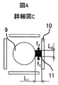
- Gravity f 1 is the distance L 1 between the respiratory filter 9 and the wall 10
- L 2 is the contact length between the salt water 11 and the respiratory filter 9, and the respiratory filter 9 in the portion protruding from the electronic control unit.
- the height is x
- the density of the salt water 11 is ⁇
- the gravity acceleration is g, it can be expressed as f 1 ⁇ L 1 L 2 x ⁇ g.
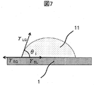
- the holding force f 2 is, as shown in FIG. 7, the contact angle when the salt water 11 is dropped on the surface of the cover 1 is ⁇ 1 , ⁇ SG is the surface tension that acts on the cover 1, and ⁇ LG is the salt water 11 that acts.
- the surface tension, ⁇ SL can be expressed as f 2 ⁇ 2x ⁇ LG cos ⁇ 1 when the interfacial tension acting on the interface of the salt water 11 is used.
- the surface tension of the salt water 11 increases as the environmental temperature is lower and the salt concentration is higher.
- the solubility of the salt water 11 is almost constant regardless of the temperature. Therefore, the maximum is surface temperature: 76 mN/m at ambient temperature: 0° C., salt water concentration (saturated solution): 26.28 wt %.
- the a cover 1 of the material is aluminum die-casting, and if the surface of the casting surface of about RZ50, the contact angle theta 1 is about 53 °, the cos [theta] 1 ⁇ 0.6.
- salt water 11 can be prevented from accumulating around the respiratory filter 9.
- the minimum distance between the wall 10 formed on the housing and the breathing filter 9 it is possible to discharge salt water by gravity, and the salt metal in the housing metal generated by the salt water is accumulated.
- the movement of electrons can be suppressed. Therefore, in the present embodiment, corrosion of the housing due to rust can be suppressed, so that an electronic control device having high salt damage resistance can be realized.
- the moldability of the cover 1 can be improved. Even in this case, the shortest distance from the point m, which is the joint between the surface k formed on the respiratory filter 9 side of the wall 10 and the curved surface R formed at the base of the wall 10 to the respiratory filter 9, is 3 mm or more. If so, it is possible to secure the drainage property equivalent to that of the first embodiment, and it is possible to realize an electronic control device having high salt damage resistance.
- FIGS. 11 to 13 A third embodiment of the present invention will be described with reference to FIGS. 11 to 13. Note that the description of the same structure as the first or second embodiment is omitted.
- the moldability of the cover 1 can be improved by providing the surface k formed on the respiratory filter 9 side of the wall 10 with a draft angle ⁇ 2 . Even in this case, if the shortest distance from the point m, which is the joint between the surface k and the curved surface R formed at the root of the wall 10, to the respiratory filter 9 is 3 mm or more, the same as in the first embodiment. Drainage can be secured and an electronic control device with high salt damage resistance can be realized.
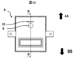
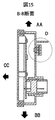
- FIGS. 14 to 16 A fourth embodiment of the present invention will be described with reference to FIGS. 14 to 16. The description of the same structure as the second embodiment is omitted. Note that the description of the same configurations as those of the first to third embodiments will be omitted.
- the AA direction shown in Fig. 15 is the upper part when the vehicle is installed, the BB direction is the lower part, and the CC direction is the vehicle traveling direction.
- the AA direction is the lower part when the vehicle is mounted and the BB direction is the upper part, it is possible to prevent the salt water rolled up from the road from being scattered linearly on the respiratory filter.
- the effect of improving the salt damage resistance obtained by the wall 10 differs depending on the vehicle mounting direction, and therefore the position of the wall may be changed according to the purpose.
- the effect of the wall 10 is enhanced as the height h of the wall 10 is set higher than x.
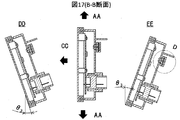
- the AA direction in FIG. 17 is the upper part when the vehicle is mounted
- the BB direction is the lower part
- the CC direction is the vehicle traveling direction
- the electronic control unit a is theta 3 inclined in CC direction
- the height of the wall is set so that the breathing filter cannot be removed from the AA direction to prevent the salt water from splashing regardless of the road surface of the vehicle. be able to.
- the height h of the wall 10 be h>x+(L 1 +y)tan ⁇ 3 where the road gradient is ⁇ 3 and the respiratory filter diameter is y.
- the diameter y of a general respiratory filter is ⁇ 17 mm
- the height x is 6.5 mm
- the gradient on the general road is ⁇ 10°
- the minimum required distance L 1 between the respiratory filter 9 and the wall 10 is 3 mm.
- h> x +(L 1 +y)tan ⁇ 3 6.5+(3+17)tan 10° ⁇ 10 mm.
- the height h of the wall 10 is set to about 1.5 times or more the height x of the breathing filter 9 to prevent salt water from splashing regardless of the road surface on which the vehicle is traveling. Therefore, it is possible to realize an electronic control device having higher salt damage resistance.
- the road gradient ⁇ 3 is not limited to 10°, and may be a larger number (for example, 20°).
- the present embodiment differs from the fourth embodiment in that in addition to the wall 10a formed in the AA direction of the respiratory filter 9, there are provided 10b and 10c formed in the GG direction and the HH direction.
- the height of the wall 10a is h a
- the height of the wall 10b is h b
- the height of the wall 10c is h c
- all of h a , h b , and h c are x +(L 1 +y)tan ⁇ It is formed to be higher than 3 .
- This embodiment compared fifth embodiment has a was further formed in the BB direction 10d, when the height of the wall 10d and the h d, h d is x + (L 1 + y) It is formed to be higher than tan ⁇ 3 and L 1d is larger than (2 ⁇ LG cos ⁇ 1 / ⁇ g) 1/2 when the minimum distance L 1d between the wall 10d and the respiratory filter 9 is set.
- the wall 10a, the wall 10b, the wall 10c, and the wall 10d are formed in four directions with respect to the breathing filter 9, it is possible to further suppress the adhesion of salt water scattered from the B direction, and to further improve the salt damage resistance.
- An electronic control device can be realized.
- the present embodiment differs from the fourth embodiment in that the wall 10 is formed so as to surround the entire circumference of the respiratory filter 9.
- the height h of the wall 10 is higher than x +(L 1 +y)tan ⁇ 3 , and the distance L 1 between the wall 10 and the respiratory filter 9 is L 1 >(2 ⁇ LG cos ⁇ 1 / ⁇ g) 1/2 .
- the present embodiment is different from the seventh embodiment in that the height of the wall formed in the direction in which salt water is most likely to be scattered (e.g., the height h a of the wall 10a formed in the AA direction) is The height is higher than the height of the wall formed in the direction (for example, the height h d of the wall 10d formed in the BB direction). As a result, it is possible to realize an electronic control device having higher salt damage resistance.
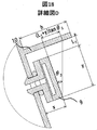
- an inclination ⁇ 4 is provided on the surface k d on the respiratory filter 9 side in the lower wall of the respiratory filter 9 (for example, the wall 10d formed in the BB direction).
- the inner wall of the wall 10d that surrounds the breathing filter 9 and is located on the lower side in the direction of gravity when the vehicle is installed is provided with a sloped portion.
- the present embodiment differs from the ninth embodiment in that a cutout 12 is provided in the lower wall of the respiratory filter 9 (for example, the wall 10d formed in the BB direction).
- a cutout 12 is provided in the lower wall of the respiratory filter 9 (for example, the wall 10d formed in the BB direction).
Landscapes
- Engineering & Computer Science (AREA)
- Microelectronics & Electronic Packaging (AREA)
- Mechanical Engineering (AREA)
- Casings For Electric Apparatus (AREA)
Abstract
塩害が厳しい搭載環境においても使用可能な電子制御装置を提供できるようにする。 上記目的を達成するために、本発明の電子制御装置は、壁と呼吸フィルタとの間の最少距離が3mm以上となるようにした。
Description
本発明は、電子制御装置に関する。
近年、自動車は、電子電動化や自動運転等の高機能化が進んでいるが、市場競争力確保のため、機能アップ分をそのまま車両価格に転嫁できない状況であり、電子制御装置を含む各構成部品の低コスト競争は益々激化している。
このような背景の中、電子制御装置に於いては、ハーネス削減、コネクタ削減を目的とした、エンジン、トランスミッション、モーター等の制御対象物との近接化及び機電一体化が進んでおり、エンジンルーム内等の過酷な温度環境・振動環境にも対応できる安価な電子制御装置が必要な状況である。
エンジンルーム内等の水が掛かる環境に電子制御装置を搭載する場合、電子制御装置を防水、防塵化する必要があるが、電子制御装置内部が完全に気密されてしまうと、温度変化により電子制御装置内/外に発生する気圧差により、筐体または防水接着剤等によるシール部が破損する懸念がある。また、電子制御装置がポンプとなり、コネクタに接続されたハーネスから電子制御内部に水を引き込んでしまい、電子部品間がショートする虞がある。そのため、電子制御装置内/外の圧力を均一に保つよう“呼吸フィルタ”を配置する必要がある。呼吸フィルタは、気圧差を調整するフィルタ膜を固定したハウジングにOリングを配置し、取り付け先の筐体とハウジングの間でOリングをつぶすことで電子制御装置内部を防水・防塵する構造が一般的に知られている。
他方、エンジンルーム内等の過酷な温度環境・振動環境に電子制御装置を搭載するためには、耐振強度の確保や電子部品の放熱を目的として、筐体にアルミダイカスト等の金属材料を用いることが一般的である。そのため、呼吸フィルタをアルミダイカスト筐体に取り付ける必要が発生する。しかし、エンジンルーム内に配置された電子制御装置には、路上から撒きあがった融雪材等を含む塩水が付着するため、金属筐体に錆が発生する。錆びによって金属筐体が腐食した場合、呼吸フィルタのOリングによる反力が失われ、電子制御装置の防水性が損なわれる虞がある。
これに対し、例えば、特許文献1のように、呼吸フィルタの周囲に壁を設けることで、呼吸フィルタに液体がかかりにくくすることが一般的に知られている。
特許文献1が課題とする液体とは車両を洗車する場合等に用いられる高圧水であり、特許文献1では、呼吸フィルタに直接高圧水があたり電子制御装置内に水が浸入することを防ぐ目的で壁を設けている。そのため、壁の高さは呼吸フィルタと同程度、且つ呼吸フィルタと壁の間の距離は可能な限り狭く設計することで、高圧水が呼吸フィルタ側部に直線的に飛散することを防止している。しかし、路上から撒きあがる塩水は直線的に飛散するものもあればミスト状のものもあり、呼吸フィルタと壁の間の狭い隙間にも侵入する。さらに、呼吸フィルタと壁との間の距離が狭ければ狭いほど、塩水の排水性は低下する。これにより塩水溜まりが発生すると、金属筐体中の電子が移動し腐食が発生する。よって、特許文献1における構造では、耐塩害性の向上について検討の余地が残されている。
本発明の目的は、塩害が厳しい搭載環境においても使用可能な電子制御装置を実現することにある。
上記目的を達成するために、本発明の電子制御装置は、壁と呼吸フィルタとの間の最少距離が3mm以上となるようにした。
本発明によれば、塩害が厳しい搭載環境においても使用可能な電子制御装置を実現できる。
以下、本発明に関する電子制御装置について実施の形態を挙げ、添付の図面を参照して詳細に説明する。
(第1の実施形態)
本発明の第1の実施形態について、図1から図7を用いて説明する。
本発明の第1の実施形態について、図1から図7を用いて説明する。
本実施形態における電子制御装置Aは、例えば、自動車に搭載されてエンジンやトランスミッションあるいはブレーキ等の制御に用いられるものである。図1と図2に示すように、電子制御装置Aは、電子部品4が実装された回路基板5と、回路基板5に実装され、回路基板5に形成される電気回路と外部機器とを電気的に接続するコネクタ3と、回路基板5が収容されるベース7と、ベース7に収容された回路基板5を覆うカバー1と、カバー1に固定される呼吸フィルタ9と、を有している。本実施例では、ベース7とカバー1との協働により、回路基板5を収容する筐体を構成している。
回路基板5は、例えばネジ2等によりカバー1あるいはベース7に保持される。また、カバー1とベース7の間には、例えば、接着剤等のシール部材(1)6が配置され、カバー1とコネクタ3の間には、例えばパッキン等のシール部材(2)8が配置されることで、電子制御装置内部を気密する。尚、回路基板5には、実際には、図示した電子部品4以外にも電子部品が複数実装されている。電子制御装置Aの内部と外部の間の気圧差を調整する呼吸フィルタ9は、筐体に形成される通気孔に固定されていて、本実施例では、カバー1に吸気フィルタ9が固定される例を示している。カバー1には、呼吸フィルタ1の周囲に壁10が形成されている。
呼吸フィルタ9は、例えば、気圧差を調整するフィルタ膜9aと、前記フィルタ膜9aを固定したハウジング9b、前記フィルタ膜9aを覆うハウジング9c、前記ハウジング9bとカバー1との間に配置されるOリング9dにて構成される。
電子制御装置Aの耐塩害性を向上させるためには、呼吸フィルタ9の周囲に塩水が溜まらないようにする必要がある。例えば、図4に示す位置に塩水11が付着した場合、塩水11が排水されるためには、塩水11の自重による重力f1が、塩水11と呼吸フィルタ9との間と、前記塩水11と前記壁10との間で発生する表面張力による保持力f2より大きい必要がある(f1 > f2)。
重力f1は、呼吸フィルタ9と前記壁10との距離をL1、塩水11と呼吸フィルタ9が接触している長さをL2、電子制御装置から突出している部分における前記呼吸フィルタ9の高さをx、塩水11の密度をρ、重力加速度をgとした時、f1≒L1L2xρgと表すことができる。
一方で、保持力f2は、図7のように、塩水11をカバー1の表面に滴下した際の接触角をθ1、γSGはカバー1にはたらく表面張力、γLGは塩水11にはたらく表面張力、γSLは塩水11の界面にはたらく界面張力とすると、f2≒2xγLGcosθ1と表すことができる。
ここでL1≒L2と仮定すると、L1
2xρg > 2xγLGcosθ1となり、重力が表面張力を上回る条件はL1 > (2γLGcosθ1/ρg)1/2となる。
塩水11の表面張力は環境温度が低く、且つ塩分濃度が高い程大きくなる。一方で、塩水11の溶解度は温度に依存せずほぼ一定である。よって、環境温度:0℃、塩水濃度(飽和溶液):26.28wt%での表面張力:76mN/mが最大となる。一方で、前記カバー1の材料がアルミダイカストであり、且つ表面がRz50程度の鋳肌の場合、接触角θ1は53°程度であり、cosθ1≒0.6となる。また、26.28wt%における塩水の密度ρは約0.001 g/mm3、重量加速度gは約9800 N/g、であることから、L1 > (2γLGcosθ1/ρg)1/2 = (2×75.6×0.6/(0.001×9800))1/2 ≒ 3mmとなる。
よって、呼吸フィルタ9と壁10の間の距離は3mm以上あれば塩水11が呼吸フィルタ9の周囲に溜まることを回避できる。本実施形態によれば、筐体に形成される壁10と呼吸フィルタ9との最少距離を3mm以上とすることで、重力により塩水を排出可能とし、塩水が溜まることで生じる筐体金属中の電子の移動を抑制できる。そのため、本実施形態は錆による筐体の腐食を抑えることができるため、耐塩害性の高い電子制御装置を実現できる。
(第2の実施形態)
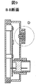
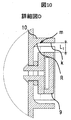
本発明の第2の実施形態について、図8から図10を用いて説明する。なお、第1の実施形態と同様の構成については説明を省略する。
本発明の第2の実施形態について、図8から図10を用いて説明する。なお、第1の実施形態と同様の構成については説明を省略する。
本実施形態は、壁10の根元に曲面Rをつけることで、カバー1の成形性を向上可能としている。この場合においても、壁10の呼吸フィルタ9側に形成された面kと壁10の根元に形成された曲面Rとのつなぎ目であるm点から呼吸フィルタ9までの最短距離が3mm以上確保されていれば、第1の実施形態と同等の排水性を確保でき、耐塩害性の高い電子制御装置を実現できる。
(第3の実施形態)
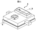
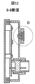
本発明の第3の実施形態について、図11から図13を用いて説明する。なお、第1または2の実施形態と同様の構造については説明を省略する。
本発明の第3の実施形態について、図11から図13を用いて説明する。なお、第1または2の実施形態と同様の構造については説明を省略する。
本実施形態は、壁10の呼吸フィルタ9側に形成された面kに抜き勾配θ2をつけることでカバー1の成形性を向上可能としている。この場合においても、面kと壁10の根元に形成された曲面Rとのつなぎ目であるm点から呼吸フィルタ9までの最短距離が3mm以上確保されていれば、第1の実施形態と同等の排水性を確保でき、耐塩害性の高い電子制御装置を実現できる。
(第4の実施形態)
本発明の第4の実施形態について、図14から図16を用いて説明する。なお、第2の実施形態と同様の構造については説明を省略する。なお、実施例1乃至3と同様の構成については説明を省略する。
本発明の第4の実施形態について、図14から図16を用いて説明する。なお、第2の実施形態と同様の構造については説明を省略する。なお、実施例1乃至3と同様の構成については説明を省略する。
例えば図15に示したAA方向が車両搭載時の上部、BB方向が下部、CC方向が車両進行方向とする。この時、図15のように呼吸フィルタ上部に壁を設けることで、路上から撒き上がり電子制御装置Aの上方から降り注ぐ塩水の付着を防ぐことが可能である。反対に、AA方向が車両搭載時の下部、BB方向が上部の場合、路上から巻き上がった塩水が呼吸フィルタに直線的に飛散することを防ぐこともできる。このように、車両搭載向きによって壁10により得られる耐塩害性向上効果が異なるため、目的に合わせて壁の位置を変化させれば良い。
さらに、呼吸フィルタ9の電子制御装置からの突出高さをxとした場合、壁10の高さhをxよりも高くすればするほど壁10の効果は高まる。例えば、図17におけるAA方向が車両搭載時の上部、BB方向が下部、CC方向が車両進行方向とした場合、車両が傾斜θ3の下り坂を走行している場合にはケースDDのように電子制御装置AがCC方向にθ3傾斜し、上り坂を走行している場合にはケースEEのようにCC方向と反対側にθ3傾斜する。この時、ケースDD、EEのいずれの場合においてもAA方向から呼吸フィルタを除くことができないよう壁の高さを設定することで、車両がいかなる路面を走行していても塩水の飛散を防止することができる。
つまり、道路の勾配を±θ3、呼吸フィルタの径をyとした時、壁10の高さhはh > x +(L1+y)tanθ3とすることが望ましいと言える。一般的な呼吸フィルタの径yはφ17mm、高さxは6.5mm、一般道路における勾配は±10°、呼吸フィルタ9と壁10の間の距離L1の必要最低距離は3mmであることから、h > x +(L1+y)tanθ3 = 6.5+(3+17)tan10° ≒ 10mmとなる。
本実施形態では、壁10の高さhを、呼吸フィルタ9の高さxに対して約1.5倍以上とすることで、車両がいかなる路面を走行していても塩水の飛散を防止することができるため、さらに耐塩害性の高い電子制御装置を実現できる。
なお、道路の勾配±θ3は10°に限定されるものではなく、それよりお大きな数字(例えば20°)としてもよい。
(第5の実施形態)
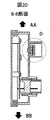
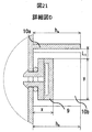
本発明の第5の実施形態について図19から図21を用いて説明する。
本発明の第5の実施形態について図19から図21を用いて説明する。
本実施形態は、第4の実施形態に対して、呼吸フィルタ9のAA方向に形成された壁10aに加え、GG方向、HH方向に形成された10b、10cを有している。壁10aの高さをha、壁10bの高さをhbと壁10cの高さをhcとしたとき、ha、hb、hcはいずれもx +(L1+y)tanθ3よりも高いように形成している。壁10aと呼吸フィルタ9との最少距離L1a、壁10bと呼吸フィルタ9との最少距離L1b、壁10cと呼吸フィルタ9との最少距離L1cとしたとき、L1a、L1b、L1a はそれぞれ(2γLGcosθ1/ρg)1/2よりもおおきくなるようにしている。本実施例では、呼吸フィルタ9に対して三方に壁10aと壁10bと壁10cを形成しているので、AA方向のみならずGG方向、HH方向から飛散する塩水の付着を抑制でき、さらに耐塩害性の高い電子制御装置を実現できる。
(第6の実施形態)
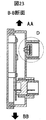
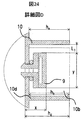
本発明の第6の実施形態について図22から図24を用いて説明する。
本発明の第6の実施形態について図22から図24を用いて説明する。
本実施形態は、第5の実施形態に対し、さらにBB方向に形成された10dを有しており、壁10dの高さをhdとしたとき、hdはx +(L1+y)tanθ3よりも高いように形成し、壁10dと呼吸フィルタ9との最少距離L1dとしたとき、L1dは(2γLGcosθ1/ρg)1/2よりも大きくなるようにしている。本実施例では、呼吸フィルタ9に対して四方に壁10aと壁10bと壁10cと壁10dを形成しているので、さらにB方向から飛散する塩水の付着を抑制でき、さらに耐塩害性の高い電子制御装置を実現できる。
(第7の実施形態)
本発明の第7の実施形態について、図25から図27を用いて説明する。
本発明の第7の実施形態について、図25から図27を用いて説明する。
本実施形態は、第4の実施形態に対して、呼吸フィルタ9の全周囲を囲うように壁10を形成している。壁10の高さhはx +(L1+y)tanθ3よりも高く、壁10と呼吸フィルタ9との距離L1はL1 > (2γLGcosθ1/ρg)1/2である。これにより、呼吸フィルタ9周囲の全方位から飛散する塩水の付着を抑制でき、さらに耐塩害性の高い電子制御装置を実現できる。
(第8の実施形態)
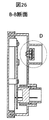
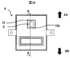
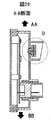
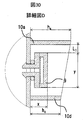
本発明の第8の実施形態について、図28から図30そ用いて説明する。
本発明の第8の実施形態について、図28から図30そ用いて説明する。
本実施形態は、第7の実施形態に対し、塩水が最も飛散する可能性が高い方向に形成された壁の高さ(例えばAA方向に形成された壁10aの高さha)が、その他の方向に形成された壁の高さ(例えばBB方向に形成された壁10dの高さhd)よりも高いようにしている。これにより、さらに耐塩害性の高い電子制御装置を実現できる。
(第9の実施形態)
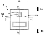
本発明の第9の実施形態について、図31から図う33を用いて説明する。
本発明の第9の実施形態について、図31から図う33を用いて説明する。
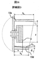
本実施形態は、第8の実施形態に対し、呼吸フィルタ9の下部の壁(例えばBB方向に形成された壁10d)における、呼吸フィルタ9側の面kdに傾斜θ4を設けている。本実施例によれば、重力により下部(面kd)に塩水が溜まりやすいところ、呼吸フィルタ9を囲う壁10のうち車両搭載時に重力方向下側に位置する壁10dの内壁に傾斜部を備えることにより、重力による塩水の排出を効率的に実施することが可能となり、耐塩害性の高い電子制御装置を実現できる。
(第10の実施形態)
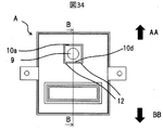
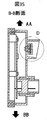
本発明の第10の実施形態について、図34から図36を用いて説明する。
本発明の第10の実施形態について、図34から図36を用いて説明する。
本実施形態は、第9の実施形態に対し、呼吸フィルタ9の下部の壁(例えばBB方向に形成された壁10d)に切欠き12を設けている。これにより、第9の実施形態に対し、面kdに付着した塩水の排水性がさらに向上し、耐塩害性の高い電子制御装置を実現できる。
A …電子制御装置
1 …カバー
2 …ネジ(基板固定用)
3 …コネクタ
4 …電子部品
5 …回路基板
6 …シール部材(1)
7 …ベース
8 …シール部材(2)
9 …呼吸フィルタ
10 …壁
10a …AA方向の壁
10b …HH方向の壁
10c …GG方向の壁
10d …BB方向の壁
11 …塩水
12 …切欠き
L1 …呼吸フィルタと壁との間の距離
L2 …呼吸フィルタ/壁と塩水の接触長さ
h …壁の高さ
ha …壁10aの高さ
hb …壁10bの高さ
hc …壁10cの高さ
hd …壁10dの高さ
θ1 …カバーの表面に塩水を滴下した際の接触角
γSG …カバーにはたらく表面張力
γLG …塩水にはたらく表面張力
γSL …カバーの界面にはたらく界面張力
k …壁の呼吸フィルタ側の面
kd …壁10dの呼吸フィルタ側の面
R …壁の根元の曲面
m …Rとk面のつなぎ目
θ2 …k面の傾斜
x …吸フィルタ9の電子制御装置からの突出高さ
y …呼吸フィルタの径
h …壁の高さ
θ3 …車両走行時の地面の傾斜
θ4 …kd面の傾斜
Claims (13)
- 電子部品が実装された回路基板と、前記基板が収容される金属製の筐体と、前記筐体に固定される呼吸フィルタと、を備える電子制御装置において、
前記筐体は壁を有し、前記壁と前記呼吸フィルタとの最少距離が3mm以上である電子制御装置。 - 前記壁の根元に曲面が形成されており、前記曲面と前記壁の呼吸フィルタ側の面とのつなぎ目から前記呼吸フィルタまでの最少距離が3mm以上である請求項1に記載の電子制御装置
- 前記壁の呼吸フィルタ側の面に傾斜を有している請求項1または2に記載の電子制御装
- 前記壁の高さが、前記呼吸フィルタの前記筐体からの突出している高さに対して1.5倍以上である請求項1乃至3の何れかに記載の電子制御装置
- 前記壁は、前記呼吸フィルタの全周を囲うように形成している請求項1乃至4の何れかに記載の電子制御装置
- 前記壁の高さが一様でない請求項5に記載の電子制御装置
- 前記壁は、少なくとも一部に切欠きを有している請求項5に記載の電子制御装置
- 電子部品が実装された回路基板と、前記基板が収容される金属製の筐体と、前記筐体に固定される呼吸フィルタと、を備える電子制御装置において、
前記筐体は壁を有し、
塩水を滴下した際の接触角をθ、塩水にはたらく表面張力をγLGとした場合、前記呼吸フィルタと前記壁との間の最少距離が(0.2γLGcosθ)1/2以上である電子制御装置 - 前記呼吸フィルタと前記壁との間の距離をL、前記呼吸フィルタの前記筐体外に突出している高さをx、前記呼吸フィルタの径をyとした場合、前記壁の高さがx+(L+y)cos10°以上である請求項8に記載の電子制御装置
- 前記呼吸フィルタと前記壁との間の距離をL、前記呼吸フィルタの前記筐体外に突出している高さをx、前記呼吸フィルタの径をyとした場合、前記壁の高さがx+(L+y)cos20°以上である請求項9に記載の電子制御装置
- 前記壁は、前記呼吸フィルタの全周を囲うように形成している請求項8乃至10の何れかに記載の電子制御装置
- 前記壁を複数備える請求項8乃至10の何れかに記載の電子制御装置
- 前記壁を複数備える請求項1乃至4の何れかに記載の電子制御装置
Priority Applications (4)
| Application Number | Priority Date | Filing Date | Title |
|---|---|---|---|
| JP2020566164A JPWO2020149091A1 (ja) | 2019-01-17 | 2019-12-19 | 電子制御装置 |
| US17/413,722 US20220071029A1 (en) | 2019-01-17 | 2019-12-19 | Electronic Control Unit |
| DE112019005772.3T DE112019005772T5 (de) | 2019-01-17 | 2019-12-19 | Elektronische steuereinheit |
| CN201980081924.XA CN113196893A (zh) | 2019-01-17 | 2019-12-19 | 电子控制装置 |
Applications Claiming Priority (2)
| Application Number | Priority Date | Filing Date | Title |
|---|---|---|---|
| JP2019-005668 | 2019-01-17 | ||
| JP2019005668 | 2019-01-17 |
Publications (1)
| Publication Number | Publication Date |
|---|---|
| WO2020149091A1 true WO2020149091A1 (ja) | 2020-07-23 |
Family
ID=71614323
Family Applications (1)
| Application Number | Title | Priority Date | Filing Date |
|---|---|---|---|
| PCT/JP2019/049748 Ceased WO2020149091A1 (ja) | 2019-01-17 | 2019-12-19 | 電子制御装置 |
Country Status (5)
| Country | Link |
|---|---|
| US (1) | US20220071029A1 (ja) |
| JP (1) | JPWO2020149091A1 (ja) |
| CN (1) | CN113196893A (ja) |
| DE (1) | DE112019005772T5 (ja) |
| WO (1) | WO2020149091A1 (ja) |
Families Citing this family (1)
| Publication number | Priority date | Publication date | Assignee | Title |
|---|---|---|---|---|
| CN212828256U (zh) * | 2019-06-05 | 2021-03-30 | 现代摩比斯株式会社 | 用于车辆的电子控制单元 |
Citations (3)
| Publication number | Priority date | Publication date | Assignee | Title |
|---|---|---|---|---|
| JP2002134939A (ja) * | 2000-10-30 | 2002-05-10 | Denso Corp | 車載用電子制御装置 |
| JP2005150376A (ja) * | 2003-11-14 | 2005-06-09 | Keihin Corp | 電子回路基板の収容ケース |
| JP2018148089A (ja) * | 2017-03-07 | 2018-09-20 | 株式会社デンソー | 電子装置 |
Family Cites Families (9)
| Publication number | Priority date | Publication date | Assignee | Title |
|---|---|---|---|---|
| JP2006005162A (ja) * | 2004-06-17 | 2006-01-05 | Denso Corp | 電子装置の防水ケース |
| JP4836677B2 (ja) * | 2005-08-24 | 2011-12-14 | 日東電工株式会社 | 通気部材 |
| JP4560477B2 (ja) * | 2005-11-15 | 2010-10-13 | 日立オートモティブシステムズ株式会社 | 電子制御装置および防水ケース |
| JP5205144B2 (ja) | 2008-07-02 | 2013-06-05 | 日立オートモティブシステムズ株式会社 | 電子制御装置 |
| JP5434669B2 (ja) * | 2010-02-26 | 2014-03-05 | 株式会社デンソー | 防水用筐体及び防水装置 |
| WO2014073096A1 (ja) * | 2012-11-09 | 2014-05-15 | トヨタ自動車株式会社 | 電子部品収容構造 |
| JP6150578B2 (ja) * | 2013-03-26 | 2017-06-21 | 日東電工株式会社 | 通気部材 |
| JP6390531B2 (ja) * | 2015-06-11 | 2018-09-19 | 株式会社デンソー | 収容部材、および、これを用いた車載用電子装置 |
| JP6816565B2 (ja) * | 2017-03-03 | 2021-01-20 | 日本精工株式会社 | 電子制御ユニットの防滴構造 |
-
2019
- 2019-12-19 US US17/413,722 patent/US20220071029A1/en not_active Abandoned
- 2019-12-19 JP JP2020566164A patent/JPWO2020149091A1/ja active Pending
- 2019-12-19 CN CN201980081924.XA patent/CN113196893A/zh active Pending
- 2019-12-19 DE DE112019005772.3T patent/DE112019005772T5/de not_active Withdrawn
- 2019-12-19 WO PCT/JP2019/049748 patent/WO2020149091A1/ja not_active Ceased
Patent Citations (3)
| Publication number | Priority date | Publication date | Assignee | Title |
|---|---|---|---|---|
| JP2002134939A (ja) * | 2000-10-30 | 2002-05-10 | Denso Corp | 車載用電子制御装置 |
| JP2005150376A (ja) * | 2003-11-14 | 2005-06-09 | Keihin Corp | 電子回路基板の収容ケース |
| JP2018148089A (ja) * | 2017-03-07 | 2018-09-20 | 株式会社デンソー | 電子装置 |
Also Published As
| Publication number | Publication date |
|---|---|
| US20220071029A1 (en) | 2022-03-03 |
| CN113196893A (zh) | 2021-07-30 |
| JPWO2020149091A1 (ja) | 2021-10-14 |
| DE112019005772T5 (de) | 2021-07-29 |
Similar Documents
| Publication | Publication Date | Title |
|---|---|---|
| JP5434669B2 (ja) | 防水用筐体及び防水装置 | |
| JP5590065B2 (ja) | 車両用電子制御ユニット | |
| US11171472B2 (en) | Electronic controller | |
| US8981240B2 (en) | Electronic circuit board case | |
| US20190052012A1 (en) | High-speed signal transmission connector with high water resistance | |
| US20180263126A1 (en) | Pressure-equalizing element and housing containing same | |
| JP6652038B2 (ja) | 電子装置 | |
| CN109216971B (zh) | 电力转换装置以及电力转换装置在车辆上的安装结构 | |
| JP2006005162A (ja) | 電子装置の防水ケース | |
| CN103181250A (zh) | 电子器件装置 | |
| CN108695645B (zh) | 树脂壳体 | |
| JPWO2020149091A1 (ja) | 電子制御装置 | |
| JP2015003621A (ja) | 電子制御装置 | |
| JP5614998B2 (ja) | 車両用電子機器 | |
| JP5610040B2 (ja) | 防水用筐体及び防水装置 | |
| US8134840B2 (en) | Circuit board and mobile electronic apparatus | |
| JP6884088B2 (ja) | 電子制御ユニット | |
| CN114342575B (zh) | 电气设备装置 | |
| JP2013091412A (ja) | 車載制御装置 | |
| JP6463981B2 (ja) | 樹脂封止型車載電子制御装置 | |
| JP7251215B2 (ja) | 車載用レーダ装置 | |
| JP2011185624A5 (ja) | ||
| JP2008189182A (ja) | 車載電装ユニット | |
| JP6205495B2 (ja) | 接続ユニット用に改善したベアリングを備えた電子装置、自動車用カメラシステム、および自動車 | |
| US20240155780A1 (en) | Electronic device |
Legal Events
| Date | Code | Title | Description |
|---|---|---|---|
| 121 | Ep: the epo has been informed by wipo that ep was designated in this application |
Ref document number: 19910215 Country of ref document: EP Kind code of ref document: A1 |
|
| ENP | Entry into the national phase |
Ref document number: 2020566164 Country of ref document: JP Kind code of ref document: A |
|
| 122 | Ep: pct application non-entry in european phase |
Ref document number: 19910215 Country of ref document: EP Kind code of ref document: A1 |