WO2020149089A1 - 送風機 - Google Patents
送風機 Download PDFInfo
- Publication number
- WO2020149089A1 WO2020149089A1 PCT/JP2019/049727 JP2019049727W WO2020149089A1 WO 2020149089 A1 WO2020149089 A1 WO 2020149089A1 JP 2019049727 W JP2019049727 W JP 2019049727W WO 2020149089 A1 WO2020149089 A1 WO 2020149089A1
- Authority
- WO
- WIPO (PCT)
- Prior art keywords
- rotating shaft
- motor
- fan
- cover
- blower
- Prior art date
- Legal status (The legal status is an assumption and is not a legal conclusion. Google has not performed a legal analysis and makes no representation as to the accuracy of the status listed.)
- Ceased
Links
Images


Classifications
-
- F—MECHANICAL ENGINEERING; LIGHTING; HEATING; WEAPONS; BLASTING
- F04—POSITIVE - DISPLACEMENT MACHINES FOR LIQUIDS; PUMPS FOR LIQUIDS OR ELASTIC FLUIDS
- F04D—NON-POSITIVE-DISPLACEMENT PUMPS
- F04D29/00—Details, component parts, or accessories
- F04D29/70—Suction grids; Strainers; Dust separation; Cleaning
Definitions
- the present disclosure relates to a blower.
- the brush motor is a motor whose rotating shaft rotates in a state where the commutator and the brush are in contact with each other.
- the fan part is fixed to the rotation shaft of the motor.
- the motor has a cooling structure for cooling the inside.
- the cooling structure is a structure in which cooling air is taken from the outside to the inside of the motor and the inside of the motor is cooled by the cooling air flowing into the inside of the motor. The cooling air is exhausted to the outside of the motor through the gap between the parts of the motor that constitute the fan-side end.
- the present disclosure has an object to provide a blower capable of suppressing the abrasion dust discharged to the outside from having any influence on the outside.
- a blower includes a motor unit with a brush, a fan unit, and a cover unit.
- the motor unit with a brush has a rotating shaft and an end portion provided with a penetrating portion through which the rotating shaft penetrates, and applies rotational power to the rotating shaft.
- the fan portion is fixed to a protruding portion of the rotating shaft that protrudes from the through portion.
- the cover part is provided between the end part of the motor part and the fan part.
- the motor part has a cooling function that takes in cooling air from the outside and cools the inside by flowing the cooling air to the end side.
- the cover portion is an annular shape that makes one round around the axis of the rotating shaft, and has a length at least from the side portion of the motor portion to the penetrating portion in the radial direction of the rotating shaft.
- the cover part is provided between the end part of the motor part and the fan part. Therefore, even if the abrasion powder generated inside the brushed motor portion passes through the end portion and is discharged to the fan portion side by the cooling function of the motor portion, the abrasion powder can be blocked by the cover portion. That is, the cover portion functions as a wall. Therefore, it is possible to prevent the abrasion powder discharged to the outside of the blower from having any effect outside the blower.
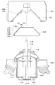
- FIG. 1 is a cross-sectional view of the blower according to the first embodiment
- 2 is an exploded view of the blower shown in FIG.
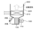
- FIG. 3 is a diagram showing a part of the HVAC device to which the blower is applied
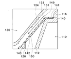
- FIG. 4 is an enlarged cross-sectional view of a part of the blower according to the second embodiment
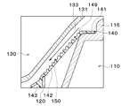
- FIG. 5 is a diagram showing a modified example of the blower according to the second embodiment
- FIG. 6 is a diagram showing a modified example of the blower according to the second embodiment.
- the blower according to this embodiment is a vehicle-mounted blower motor. As shown in FIGS. 1 and 2, the blower 100 includes a motor unit 110, a motor holder 120, a fan unit 130, and a cover unit 140.
- the motor unit 110 is configured as a brushed motor.
- the motor unit 110 has a case 111, an end 112, and a rotating shaft 113.
- the case 111 is made of a magnetic material such as iron and has a bottomed cylindrical shape.
- the case 111 is a yoke forming a magnetic circuit.
- the bottom 114 of the case 111 is provided with an inlet 115 through which cooling air for cooling the inside of the motor 110 flows.
- the end 112 is a lid part of the case 111.
- the end 112 is provided on the opening side of the case 111.
- the end 112 is inclined toward the bottom 114 side of the case 111 with respect to a plane perpendicular to the central axis of the rotating shaft 113.
- the end portion 112 has a penetrating portion 116.
- the penetrating portion 116 constitutes a through hole through which the rotary shaft 113 penetrates.
- the rotating shaft 113 is arranged so that its central axis coincides with the cylindrical axis of the case 111.
- One end side of the rotating shaft 113 is housed inside the case 111.
- the other end side of the rotary shaft 113 projects from the penetrating portion 116 of the end 112.
- One end of the rotating shaft 113 is supported by a bearing (not shown) provided on the bottom 114 of the case 111.
- the other end of the rotating shaft 113 is supported by a bearing (not shown) provided in the penetrating portion 116.
- the rotary shaft 113 can rotate about the central axis.
- the motor unit 110 includes a rotor, a commutator, a brush, a stator, and the like as parts not shown.
- the rotor is a component in which a coil is wound around a rotor core.
- the rotor is fixed to the rotating shaft 113 and is housed in the case 111.
- the rotor rotates together with the rotating shaft 113.
- the rotation of the rotor gives rotational power to the rotating shaft 113.
- the commutator is arranged between the through portion 116 and the rotor in the axial direction of the rotating shaft 113.
- the commutator is fixed to the rotating shaft 113.
- the commutator rotates together with the rotating shaft 113.
- the brush is housed in the case 111 so as to contact the commutator.
- the commutator and the brush are made of a conductive metal material such as copper.
- the stator is composed of multiple permanent magnets.
- the plurality of permanent magnets are housed in the case 111 and arranged outside the rotor in the radial direction of the rotating shaft 113.
- the plurality of permanent magnets are arranged in the circumferential direction of the rotary shaft 113.
- the motor holder 120 is a component that supports the case 111 of the motor unit 110.
- the motor holder 120 accommodates the motor unit 110 so as to cover the side portion 117 of the motor unit 110.
- the side part 117 of the motor part 110 corresponds to the outer wall surface of the case 111 in the radial direction of the rotating shaft 113.
- the motor holder 120 constitutes an air flow path for guiding the cooling air to the inflow port 115 of the case 111. That is, the motor unit 110 has a cooling function of taking in cooling air from the outside and cooling the inside by flowing the cooling air toward the end 112 side. As a result, as shown by the arrow in FIG. 1, the cooling air moves inside the motor unit 110 from the bottom 114 toward the end 112. That is, the cooling air moving inside the motor unit 110 cools the motor unit 110.
- the fan unit 130 shown in FIGS. 1 and 2 is a fan for a blower motor.
- the fan unit 130 has a main plate 131 and a blade 132.
- the central portion of the main plate 131 is fixed to a protruding portion 118 of the rotary shaft 113 that protrudes from the through portion 116.
- the main plate 131 has a substantially conical shape that is convex toward the tip of the protruding portion 118 of the rotating shaft 113.
- the main plate 131 covers the entire end 112 of the motor unit 110.
- the wing portion 132 is provided on the side of the main plate 131 opposite to the motor portion 110.
- the main plate 131 transmits the rotational power of the motor section 110 to the wing section 132.
- the fan unit 130 blows out the airflow sucked from the region opposite to the motor unit 110 in the radial direction of the rotary shaft 113 in the axial direction of the rotary shaft 113. That is, the fan unit 130 is a centrifugal fan.
- the cover 140 is provided between the end 112 of the motor 110 and the fan 130.
- the cover portion 140 is a component for blocking abrasion powder generated by the contact between the commutator and the brush inside the motor portion 110.
- the cover portion 140 is an annular component that makes a round around the axis of the rotating shaft 113.
- the cover portion 140 has at least a length from the side portion 117 of the motor portion 110 to the penetrating portion 116 in the radial direction of the rotating shaft 113. That is, the cover part 140 covers the part of the end part 112 excluding the penetrating part 116.
- the cover part 140 has a disc part 141, a funnel part 142, and a ring part 143.
- the disc portion 141 has a window portion 144.
- the window portion 144 is a portion where the penetrating portion 116 is arranged.
- the window portion 144 is a through hole having a size through which the through portion 116 passes.
- the funnel portion 142 is a funnel-shaped portion of the cover portion 140.
- the funnel shape is a shape in which the diameter of one opening of the cylinder is smaller than the diameter of the other opening. It can be said that the funnel shape is the outer shape of a truncated cone.
- the funnel portion 142 corresponds to the shape of the end portion 112 of the motor portion 110.
- the funnel portion 142 has a small diameter portion 145 and a large diameter portion 146.
- the small diameter portion 145 is integrated with the outer edge portion 147 of the disc portion 141.
- the large diameter portion 146 is a portion where the diameter of the opening is larger than that of the small diameter portion 145.
- the funnel portion 142 is inclined toward the bottom portion 114 side of the case 111 with respect to a plane perpendicular to the central axis of the rotating shaft 113.
- the outer shape of the funnel portion 142 may be formed into a truncated pyramid shape such as a truncated pyramid shape according to the outer shape of the end portion 112 of the motor unit 110. Further, depending on the shape of the end portion 112 of the motor unit 110, a portion of the funnel portion 142 that comes into contact with the end portion 112 may occur. In this case, in order to avoid the interference between the end 112 and the funnel portion 142, the funnel portion 142 may be provided with a through hole.
- the ring portion 143 is a cylindrical portion.
- the ring portion 143 also has a function of preventing water from entering the motor portion 110.
- the ring portion 143 is integrated with the outer edge portion 148 of the large diameter portion 146 of the funnel portion 142.
- the ring portion 143 is fixed to the motor holder 120 by a hooking structure such as a snap fit.
- the ring part 143 may be fixed to the side part 117 of the motor part 110.
- the cover part 140 is formed of a resin material such as polypropylene. Although depending on the size of the blower 100, the thickness of the cover portion 140 is, for example, about 1 mm. The thickness of the cover portion 140 is appropriately set according to the gap between the end portion 112 of the motor portion 110 and the fan portion 130.
- the cover part 140 has a surface 149 facing the fan part 130.
- the main plate 131 has a surface 133 facing the cover portion 140. Then, at least a part of the facing surfaces where the surface 149 of the cover portion 140 and the surface 133 of the main plate 131 face each other are arranged in parallel.
- the cooling air passing through the inside of the motor unit 110 is discharged to the outside of the motor unit 110 through the penetrating portion 116, the cooling air passes between the surface 149 of the cover unit 140 and the surface 133 of the main plate 131. Since the surface 149 of the cover part 140 and the surface 133 of the main plate 131 are arranged in parallel, there is an advantage that the flow of the cooling air passing between the cover part 140 and the main plate 131 is not obstructed.
- parallel includes not only the case of being completely parallel but also the case of being parallel to some extent. It is preferable that they are completely parallel, but it is sufficient that the parallelism is such that an effect can be obtained in consideration of an error due to assembly. Further, it is difficult to make all the facing surfaces of the surface 149 of the cover part 140 and the surface 133 of the main plate 131 parallel to each other. Therefore, it suffices if at least a part of the facing surfaces are parallel.
- the above is the configuration of the blower 100.
- the blower 100 is applied to a vehicle HVAC device 200 (Heating, Ventilation and Air conditioning unit; HVAC).
- HVAC device 200 is an air conditioner for adjusting the temperature inside the vehicle.
- the fan unit 130 and the evaporator 210 of the blower 100 are housed in the case 220.
- the blower 100 is arranged upstream of the air flow with respect to the evaporator 210 mounted on the vehicle.
- the evaporator 210 is a heat exchanger that cools the air blown from the blower 100.
- the evaporator 210 is made of a material different from that of the commutator and the brush of the motor unit 110.
- the evaporator 210 is made of aluminum or an alloy containing aluminum.
- Inside air and outside air are switched and introduced into the case 220.
- the inside air or the outside air introduced into the case 220 is blown to the evaporator 210 side by the blower 100.
- the temperature of the blown air that has passed through the evaporator 210 is adjusted and blown into the vehicle compartment through the air outlet.
- the abrasion powder generated inside the motor unit 110 with a brush passes through the end 112 as shown by the arrow in FIG. Is discharged to.
- the cover part 140 since the cover part 140 is provided between the end part 112 of the motor part 110 and the fan part 130, the cover part 140 functions as a wall. Therefore, the cover portion 140 can block the abrasion powder. Therefore, it is possible to suppress the abrasion powder discharged to the outside of the blower 100 from having any influence on the outside of the blower 100.
- the commutator and brush do not need to be made of highly wear-resistant material. Since the material having high wear resistance is expensive, the cost of the motor unit 110 is significantly increased. However, the resin cover portion 140 can reduce the cost as compared with a case where the commutator and the brush are made of a material having high wear resistance. Of course, it is not necessary to change the materials of the commutator and the brush.
- the abrasion powder discharged from the blower 100 is copper powder.
- the copper powder reaches the evaporator 210, it becomes an oxidation catalyst for the evaporator 210 including aluminum. Therefore, the evaporator 210 is corroded.
- the blower 100 is provided with the cover portion 140, it is possible to reduce the amount of abrasion powder that reaches the evaporator 210 from the blower 100. Therefore, the corrosion resistance of the evaporator 210 can be improved.
- the inventors of the present disclosure examined the amount of wear debris reaching the evaporator 210.
- the arrival amount of the abrasion powder that reached the evaporator 210 was smaller than when the cover part 140 was not provided. From this result, the effect of the cover part 140 was confirmed.
- the surface 149 of the cover part 140 has an uneven part 150 in which unevenness is repeated in the radial direction of the rotating shaft 113.
- the surface 133 of the fan unit 130 has an uneven portion 134 in which unevenness is repeated in the radial direction of the rotating shaft 113.
- the uneven portions 134 and 150 are provided continuously or intermittently in the radial direction of the rotating shaft 113.
- the peaks and valleys of the uneven portions 134 and 150 are provided continuously or intermittently in the circumferential direction of the rotating shaft 113.
- the uneven portion 150 of the cover 140 is continuously provided in the radial direction.
- the concavo-convex portion 134 of the fan unit 130 is provided intermittently in the radial direction.
- the continuous shape and the intermittent shape are determined by the shape of the cover portion 140, the shape of the main plate 131 of the fan portion 130, and the relationship with other structures.
- the abrasion powder moving along with the cooling air passing between the cover part 140 and the main plate 131 of the fan part 130 is collected by the uneven part 150 of the cover part 140 and the uneven part 134 of the fan part 130.
- the cover portion 140 may be provided with the uneven portion 150, and the main plate 131 of the fan portion 130 may not be provided with the uneven portion 134.
- the main plate 131 of the fan unit 130 may be provided with the uneven portion 134, and the cover portion 140 may not be provided with the uneven portion 150.
- the blower 100 is not limited to the vehicle-mounted type.
- the blower 100 can be appropriately used in a situation where ventilation is required.
- the end 112 of the motor unit 110 may be parallel to a plane perpendicular to the central axis of the rotating shaft 113. That is, the shape of the cover portion 140 is formed according to the outer shape of the end portion 112 of the motor portion 110.
Landscapes
- Engineering & Computer Science (AREA)
- Mechanical Engineering (AREA)
- General Engineering & Computer Science (AREA)
- Structures Of Non-Positive Displacement Pumps (AREA)
Applications Claiming Priority (2)
| Application Number | Priority Date | Filing Date | Title |
|---|---|---|---|
| JP2019004204A JP2020112114A (ja) | 2019-01-15 | 2019-01-15 | 送風機 |
| JP2019-004204 | 2019-01-15 |
Publications (1)
| Publication Number | Publication Date |
|---|---|
| WO2020149089A1 true WO2020149089A1 (ja) | 2020-07-23 |
Family
ID=71613306
Family Applications (1)
| Application Number | Title | Priority Date | Filing Date |
|---|---|---|---|
| PCT/JP2019/049727 Ceased WO2020149089A1 (ja) | 2019-01-15 | 2019-12-19 | 送風機 |
Country Status (2)
| Country | Link |
|---|---|
| JP (1) | JP2020112114A (enExample) |
| WO (1) | WO2020149089A1 (enExample) |
Cited By (1)
| Publication number | Priority date | Publication date | Assignee | Title |
|---|---|---|---|---|
| DE102022205348A1 (de) | 2022-05-30 | 2023-11-30 | Robert Bosch Gesellschaft mit beschränkter Haftung | Motorkühlvorrichtung |
Citations (2)
| Publication number | Priority date | Publication date | Assignee | Title |
|---|---|---|---|---|
| WO2015136829A1 (ja) * | 2014-03-14 | 2015-09-17 | 株式会社デンソー | 遠心式多翼送風機 |
| JP2015214939A (ja) * | 2014-05-12 | 2015-12-03 | 株式会社デンソー | ブロワ装置 |
-
2019
- 2019-01-15 JP JP2019004204A patent/JP2020112114A/ja active Pending
- 2019-12-19 WO PCT/JP2019/049727 patent/WO2020149089A1/ja not_active Ceased
Patent Citations (2)
| Publication number | Priority date | Publication date | Assignee | Title |
|---|---|---|---|---|
| WO2015136829A1 (ja) * | 2014-03-14 | 2015-09-17 | 株式会社デンソー | 遠心式多翼送風機 |
| JP2015214939A (ja) * | 2014-05-12 | 2015-12-03 | 株式会社デンソー | ブロワ装置 |
Cited By (1)
| Publication number | Priority date | Publication date | Assignee | Title |
|---|---|---|---|---|
| DE102022205348A1 (de) | 2022-05-30 | 2023-11-30 | Robert Bosch Gesellschaft mit beschränkter Haftung | Motorkühlvorrichtung |
Also Published As
| Publication number | Publication date |
|---|---|
| JP2020112114A (ja) | 2020-07-27 |
Similar Documents
| Publication | Publication Date | Title |
|---|---|---|
| US10082146B2 (en) | Blower | |
| JP2002254337A (ja) | 電動工具 | |
| US20160305435A1 (en) | Centrifugal multiblade blower | |
| US11332052B2 (en) | Centrifugal blower device | |
| WO2007094350A1 (ja) | 回転電機の冷却構造 | |
| JP2014136997A (ja) | 汚れ固着防止機能を有するファンモータおよびファンモータを有する装置 | |
| JP6447713B2 (ja) | 送風装置 | |
| WO2020149089A1 (ja) | 送風機 | |
| JP4559812B2 (ja) | 電動送風機 | |
| EP3456978B1 (en) | Blower device | |
| JPWO2020251041A5 (enExample) | ||
| WO2008146155A2 (en) | Ventilation unit | |
| JP5542984B1 (ja) | 車両用交流発電機 | |
| KR102663459B1 (ko) | 차량용 공조장치 | |
| KR102584420B1 (ko) | 차량용 공조장치 | |
| US20170054345A1 (en) | Cover assembly and motor | |
| KR102707442B1 (ko) | 차량용 공조장치 | |
| CN110574262B (zh) | 电动机 | |
| KR20170027455A (ko) | 차량용 냉각팬 모터 | |
| JP2020040500A (ja) | 送風装置、空調装置 | |
| JP4611144B2 (ja) | プロペラファン | |
| JP6551287B2 (ja) | ファン装置 | |
| JP6421610B2 (ja) | 送風機 | |
| JP2006217773A (ja) | ファンモータ | |
| JP2009171751A (ja) | ファンモータ |
Legal Events
| Date | Code | Title | Description |
|---|---|---|---|
| 121 | Ep: the epo has been informed by wipo that ep was designated in this application |
Ref document number: 19910297 Country of ref document: EP Kind code of ref document: A1 |
|
| NENP | Non-entry into the national phase |
Ref country code: DE |
|
| 122 | Ep: pct application non-entry in european phase |
Ref document number: 19910297 Country of ref document: EP Kind code of ref document: A1 |