WO2020149021A1 - Générateur d'itinéraire, procédé de génération d'itinéraire et programme de génération d'itinéraire - Google Patents
Générateur d'itinéraire, procédé de génération d'itinéraire et programme de génération d'itinéraire Download PDFInfo
- Publication number
- WO2020149021A1 WO2020149021A1 PCT/JP2019/046326 JP2019046326W WO2020149021A1 WO 2020149021 A1 WO2020149021 A1 WO 2020149021A1 JP 2019046326 W JP2019046326 W JP 2019046326W WO 2020149021 A1 WO2020149021 A1 WO 2020149021A1
- Authority
- WO
- WIPO (PCT)
- Prior art keywords
- robot
- obstacle
- route
- information
- clearance
- Prior art date
Links
Images


Classifications
-
- B—PERFORMING OPERATIONS; TRANSPORTING
- B25—HAND TOOLS; PORTABLE POWER-DRIVEN TOOLS; MANIPULATORS
- B25J—MANIPULATORS; CHAMBERS PROVIDED WITH MANIPULATION DEVICES
- B25J9/00—Programme-controlled manipulators
- B25J9/16—Programme controls
- B25J9/1656—Programme controls characterised by programming, planning systems for manipulators
- B25J9/1671—Programme controls characterised by programming, planning systems for manipulators characterised by simulation, either to verify existing program or to create and verify new program, CAD/CAM oriented, graphic oriented programming systems
-
- B—PERFORMING OPERATIONS; TRANSPORTING
- B25—HAND TOOLS; PORTABLE POWER-DRIVEN TOOLS; MANIPULATORS
- B25J—MANIPULATORS; CHAMBERS PROVIDED WITH MANIPULATION DEVICES
- B25J13/00—Controls for manipulators
- B25J13/08—Controls for manipulators by means of sensing devices, e.g. viewing or touching devices
- B25J13/088—Controls for manipulators by means of sensing devices, e.g. viewing or touching devices with position, velocity or acceleration sensors
- B25J13/089—Determining the position of the robot with reference to its environment
-
- B—PERFORMING OPERATIONS; TRANSPORTING
- B25—HAND TOOLS; PORTABLE POWER-DRIVEN TOOLS; MANIPULATORS
- B25J—MANIPULATORS; CHAMBERS PROVIDED WITH MANIPULATION DEVICES
- B25J9/00—Programme-controlled manipulators
- B25J9/16—Programme controls
- B25J9/1656—Programme controls characterised by programming, planning systems for manipulators
- B25J9/1664—Programme controls characterised by programming, planning systems for manipulators characterised by motion, path, trajectory planning
- B25J9/1666—Avoiding collision or forbidden zones
-
- G—PHYSICS
- G05—CONTROLLING; REGULATING
- G05B—CONTROL OR REGULATING SYSTEMS IN GENERAL; FUNCTIONAL ELEMENTS OF SUCH SYSTEMS; MONITORING OR TESTING ARRANGEMENTS FOR SUCH SYSTEMS OR ELEMENTS
- G05B2219/00—Program-control systems
- G05B2219/30—Nc systems
- G05B2219/40—Robotics, robotics mapping to robotics vision
- G05B2219/40476—Collision, planning for collision free path
-
- G—PHYSICS
- G05—CONTROLLING; REGULATING
- G05B—CONTROL OR REGULATING SYSTEMS IN GENERAL; FUNCTIONAL ELEMENTS OF SUCH SYSTEMS; MONITORING OR TESTING ARRANGEMENTS FOR SUCH SYSTEMS OR ELEMENTS
- G05B2219/00—Program-control systems
- G05B2219/30—Nc systems
- G05B2219/40—Robotics, robotics mapping to robotics vision
- G05B2219/40519—Motion, trajectory planning
Definitions
- the present invention relates to a route generation device, a route generation method, and a route generation program.
- Patent Document 1 a simulation of a motion program of a robot is executed, a motion path acquisition unit that acquires a first motion path and an interference in the first motion path are detected, and before and after the interference occurs. Between the first and second teaching points and the teaching point specifying unit that specifies the first teaching point and the second teaching point, which are the teaching points, and at least one of the first and second teaching points based on the search direction and the search distance defined by random numbers. An operation path generation unit that automatically inserts the third teaching point to generate a second operation path that does not cause interference, and an evaluation based on at least one predetermined parameter for each of the second operation paths.
- a robot simulation apparatus is disclosed that includes an evaluation unit that performs the operation, and an operation path selection unit that selects an optimum operation path from a plurality of second operation paths based on the evaluation.
- the route is created so that the robot does not interfere with the obstacle, that is, the distance between the robot and the obstacle keeps a safe distance.
- the clearance amount indicating the safe distance between the robot and the obstacle has been set uniformly for the robot or the obstacle.
- the clearance amount is set uniformly for robots or obstacles, for example, in a pick-and-place device
- the clearance amount of the box in which the work is stored is set to be large in order to enhance safety
- the corner of the box Increases the probability of failing to pick the workpiece. Therefore, the overall success rate of picking is reduced.
- the clearance amount is set to be small in order to increase the picking success rate, the safety will be reduced. That is, the risk of the robot interfering with an obstacle increases.
- the present invention has been made in view of the above points, and it is possible to prevent a decrease in the success rate of the operation of a robot and a decrease in the safety of the operation of the robot, and a path generation device and a path.
- the purpose is to provide a generator.
- a first aspect of the disclosure is a path generation device, which includes posture information regarding an initial posture and a target posture of a robot, position information regarding a position of the robot, and obstacles including positions of obstacles existing within a range where the robot interferes with the obstacle. Based on the positional relationship between the robot and the obstacle, and an obstacle existing within a range where the robot and the robot interfere with each other, based on a positional relationship between the robot and the obstacle.
- a setting unit that sets a clearance amount that indicates the amount of clearance for avoiding the interference, an initial posture and a target posture of the robot, a position of the robot, a position of the obstacle, and a shape of the robot.
- a route generation unit that generates route information regarding the route of the robot based on the clearance amount set by the setting unit.
- the setting unit reduces the clearance amount when the route generated by the route generation unit does not satisfy a predetermined route condition, and the route generation unit sets the initial posture of the robot and The route information may be regenerated based on the target posture, the position of the robot, the position of the obstacle, the shape of the robot, and the clearance amount set by the setting unit.
- the setting unit clears the obstacle without the dent.
- a clearance amount smaller than the amount may be set.
- the setting unit calculates the velocity or acceleration of the joint of the robot based on the route information, and when the calculated velocity or acceleration of the joint of the robot is equal to or more than a predetermined threshold value, the velocity Alternatively, the clearance amount may be increased so that the acceleration becomes less than a predetermined threshold value.
- the setting unit may receive an adjustment coefficient for adjusting the clearance amount, and adjust a plurality of the clearance amounts based on the received adjustment coefficient.
- the display control unit may be configured to control the display of the obstacle to be different according to the clearance amount.
- a second aspect of the disclosure is a route generation method, in which a computer includes posture information regarding an initial posture and a target posture of a robot, position information regarding a position of the robot, and a position of an obstacle existing within a range where the computer interferes with the robot. Existing in a range in which the robot and the robot interfere with each other, based on an acquisition step of acquiring the obstacle information including the specification information regarding the specification including the shape of the robot, and the positional relationship between the robot and the obstacle.
- a third aspect of the disclosure is a route generation program, which uses a computer to set posture information regarding an initial posture and a target posture of a robot, position information regarding a position of the robot, and a position of an obstacle existing within a range where the robot interferes with the robot. And an obstacle existing within a range where the robot and the robot interfere with each other based on the positional information between the robot and the obstacle.
- a setting unit that sets a clearance amount that represents the amount of clearance for avoiding the interference, an initial posture and a target posture of the robot, a position of the robot, a position of the obstacle, and the robot.
- a route generation unit that generates route information regarding the route of the robot based on the shape and the clearance amount set by the setting unit.
- the present invention it is possible to prevent the safety rate of the robot operation from being reduced while preventing the success rate of the robot operation from being reduced.
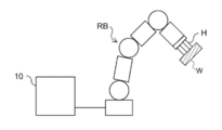
- 1 is a diagram showing a schematic configuration of a robot and a robot controller.
- the robot controller 10 is connected to the robot RB and controls the operation of the robot RB.
- the robot controller 10 controls the operation of the robot RB by outputting various parameters (operation command values) for controlling the operation of the robot RB to the robot RB.
- the robot control device 10 also has a function as a route generation device that generates a route for the robot RB. The detailed configuration of the robot controller 10 will be described later.
- the robot RB moves along a plurality of teaching points taught by a user or a plurality of waypoints generated from a route plan.
- the various operation command values include, for example, speed, acceleration, deceleration, and rotation angle of the joint of the robot RB.
- the robot hand H is attached to the tip as an end effector.
- the robot RB is, for example, a so-called pick-and-place robot that grips the work W, which is an operation target of the robot RB, at a predetermined position, and transports and places it to a predetermined destination.
- the robot RB has a tool attached as an end effector. In this case, the robot RB moves according to the taught route or the route based on the route plan, and performs predetermined processing such as welding, screwing, and inspection at a predetermined place.
- the configuration of the robot RB will be described.
- the robot RB is a vertical articulated robot
- the present invention is also applicable to horizontal articulated robots (scalar robots), parallel link robots, orthogonal robots, mobile robots, flying robots (drones), humanoid robots, and the like.
- FIG. 2 is a diagram showing a configuration of a robot which is a vertical articulated robot.
- the robot RB is a 6-degree-of-freedom 6-axis robot including a base link BL, links L1 to L6, and joints J1 to J6.
- the joint is a joint that connects the links.
- the joints J1 to J6 rotatably connect the links by a motor (not shown).
- a 6-axis robot is described as an example, but the number of axes is not limited to 6, and any number of 2 or more may be used. The number of links changes with the number of axes.
- the base link BL and the link L1 are connected via a joint J1 which rotates in the direction of arrow C1 about the vertical axis S1 in FIG. Therefore, the link L1 rotates in the direction of arrow C1 with the base link BL as a fulcrum.
- the link L1 and the link L2 are connected via a joint J2 that rotates in the direction of arrow C2 about the horizontal axis S2 in FIG. Therefore, the link L2 rotates in the arrow C2 direction with the joint J1 as a fulcrum.
- the link L2 and the link L3 are connected via a joint J3 that rotates in the direction of arrow C3 about the axis S3 in FIG. Therefore, the link L3 rotates in the direction of arrow C3 with the joint J2 as a fulcrum.
- the link L3 and the link L4 are connected via a joint J4 that rotates about the axis S4 in the direction of arrow C4 in FIG. Therefore, the link L4 rotates in the arrow C4 direction with the joint J3 as a fulcrum.
- the link L4 and the link L5 are connected via a joint J5 that rotates about the axis S5 in the direction of arrow C5 in FIG. Therefore, the link L5 rotates in the direction of arrow C5 with the joint J4 as a fulcrum.
- the link L5 and the link L6 are connected via a joint J6 which rotates about the axis S6 in the direction of arrow C6 in FIG. Therefore, the link L6 rotates in the direction of arrow C6 with the joint J5 as a fulcrum.
- the robot hand H is attached to the link L6.
- the joints J1 to J6 have their respective ranges of rotation angles set as movable ranges.
- the position of the hand of the robot RB or the posture of the robot RB is determined by the rotation angles of the joints J1 to J6. Therefore, when teaching the route to the robot RB, the angle values of the rotation angles of the joints J1 to J6 are expressed as a vector having a dimension corresponding to the number of axes of the robot (a 6-dimensional vector in the case of the present embodiment). Then, the vector is sequentially taught as a teaching point. In the case where the route is generated instead of being taught, similarly, the waypoints through which the robot RB passes are generated as a dimensional vector corresponding to the number of axes of the joints J1 to J6.
- vector data having coordinate values on the Cartesian coordinate system may be given as the motion path, instead of vector data having angle values at the teaching point or the waypoint.
- the coordinate values on the Cartesian coordinate system can be converted into the angle values of the joints J1 to J6 based on the inverse kinematics of the robot.
- FIG. 3 is a block diagram showing the hardware configuration of the robot controller 10.
- the robot controller 10 includes a CPU (Central Processing Unit) 11, a ROM (Read Only Memory) 12, a RAM (Random Access Memory) 13, a storage 14, an input unit 15, a monitor 16 and an optical disk drive device. 17 and a communication interface 18.
- the components are connected via a bus 19 so that they can communicate with each other.
- the ROM 12 or the storage 14 stores a robot control program for controlling the robot RB.
- the CPU 11 is a central processing unit and executes various programs and controls each component. That is, the CPU 11 reads the program from the ROM 12 or the storage 14 and executes the program using the RAM 13 as a work area.
- the CPU 11 controls the above-mentioned components and performs various arithmetic processes according to a program recorded in the ROM 12 or the storage 14.
- the ROM 12 stores various programs and various data.
- the RAM 13 temporarily stores a program or data as a work area.
- the storage 14 is configured by an HDD (Hard Disk Drive) or SSD (Solid State Drive), and stores various programs including an operating system and various data.
- the input unit 15 includes a keyboard 151 and a pointing device such as a mouse 152, and is used for performing various inputs.
- the monitor 16 is, for example, a liquid crystal display, and displays various kinds of information such as success or failure of suction of the work W.
- the monitor 16 may employ a touch panel method and function as the input unit 15.
- the optical disc driving device 17 reads data stored in various recording media (CD-ROM, Blu-ray disc, etc.) and writes data to the recording media.
- the communication interface 18 is an interface for communicating with other devices, and for example, a standard such as Ethernet (registered trademark), FDDI or Wi-Fi (registered trademark) is used.
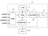
- FIG. 4 is a block diagram showing an example of the functional configuration of the robot controller 10.
- the robot control device 10 has an acquisition unit 20, a setting unit 22, a route generation unit 24, and a display control unit 26 as functional configurations.
- Each functional configuration is realized by the CPU 11 reading a robot control program stored in the ROM 12 or the storage 14, loading the robot control program in the RAM 13, and executing the program.
- the acquisition unit 20 acquires posture information, position information, obstacle information, and specification information. These pieces of information may be acquired by reading the information stored in the storage 14 in advance, or may be acquired from an external device.
- the posture information is information about the initial posture and the target posture of the robot RB.
- the position information is information on the position of the robot RB and includes, for example, coordinate values of the position of the robot RB in the three-dimensional space.
- the obstacle information is information including the position of an obstacle existing within a range where it interferes with the robot RB, that is, the position of a structure that becomes an obstacle in the operation of the robot RB, and for example, the coordinate value of the position of the obstacle in the three-dimensional space. including.
- the interference means contact with the robot RB.
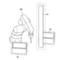
- the types of obstacles include a box 30 in which a work is accommodated, a shelf 32 on which the work is placed, a pedestal 34 on which the box 30 is installed, a pedestal 36 on which the shelf 32 is installed, and a camera for photographing the operation of the robot RB.
- the obstacle information includes, for example, three-dimensional shape data indicating the three-dimensional shape and size of the obstacle or the type of obstacle, in addition to the information on the position of the obstacle.
- the specification information is information about specifications including the shape of the robot RB.
- the specification information includes information indicating specifications such as the maximum speed, the maximum acceleration, the maximum deceleration, and the angular range that the rotation angle can take, in addition to the shapes of the joints J1 to J6 of the robot RB. ..
- the setting unit 22 avoids the interference between the robot RB and the obstacle with respect to at least one of the robot RB and the obstacle existing within the range where the robot RB interferes with the robot RB based on the positional relationship between the robot RB and the obstacle. Set the amount of clearance that represents the amount of clearance.
- the clearance amount may be set for the entire robot RB, or the clearance amount may be set individually for each of the joints J1 to J6. In the present embodiment, a case where a clearance amount is set individually for each joint will be described.
- the clearance amount may be set only for the robot RB, the clearance amount may be set only for the obstacle, or the clearance amount may be set for both the robot RB and the obstacle. Further, when there are a plurality of obstacles, the clearance amount may be set for all the obstacles, or the clearance amount may be set for only some of the obstacles.
- the route generation unit 24 generates route information regarding the route of the robot RB based on the initial posture and the target posture of the robot RB, the position of the robot RB, the position of the obstacle, the shape of the robot, and the clearance amount set by the setting unit 22. To generate.
- the route information is information about the route from the initial posture of the robot RB to the target posture and the speed at which the robot RB moves along the route.
- the path is a list of postures when the robot RB is moved from the initial posture to the target posture.
- the route is the rotation of each joint J1 to J6 at the teaching point or the passing point of the robot RB from the initial posture of the robot RB to the target posture. It is a list of angle values of angles.
- the information regarding the speed is, for example, a speed profile that represents a change in speed when the robot RB moves from the initial posture to the target posture.
- the speed of the robot RB is controlled according to the speed profile to move along the path.
- the display control unit 26 executes various display control processes such as displaying the robot RB and the obstacle for which the clearance amount is set on the monitor 16.
- FIG. 6 is a flowchart showing the flow of robot control processing by the robot control device 10.
- the CPU 11 reads out the robot control program from the ROM 12 or the storage 14, expands it in the RAM 13, and executes it to perform robot control processing.
- the robot control process includes a route generation process.
- the CPU 11 acquires the posture information of the robot RB, the position information of the robot RB, the obstacle information about the obstacle, and the specification information of the robot RB (step S100).
- the CPU 11 individually sets a clearance amount indicating the amount of clearance for avoiding the interference between the robot RB and the obstacle for at least one of the robot RB and the obstacle existing within the range in which the robot RB interferes (step S102).
- the clearance amount can be set individually by the user.
- the display control unit 26 causes the monitor RB to display the robot RB based on the specification information and causes the monitor 16 to display the obstacle based on the obstacle information.
- the user inputs the clearance amount to at least one of the joints and the obstacle of the robot RB by the input unit 15 based on the positional relationship between the robot RB and the obstacle. Accordingly, the clearance amount can be set for at least one of the robot RB and the obstacle.
- the clearance amount may be automatically set according to the clearance amount setting information 50 as shown in FIG. 7, for example.
- the clearance amount setting information 50 is table data representing the correspondence between the clearance setting target and the clearance amount.
- the clearance amount is set for each of the joints J1 to J6 in the robot RB.
- the clearance amount of the joints J1 to J3, which are the joints on the root side, is set to 10 mm. Setting the clearance amount of 10 mm in the joint J1 means that the thickness is increased by 10 mm in the normal direction to the surface of the joint J1.
- the clearance amount of joints J4 to J6, which are the joints on the hand side is set to 5 mm. That is, the clearance amount on the hand side is set smaller than the clearance amount on the joint on the root side.
- the joints J4 to J6 on the hand side may rush into the recessed portion of the recessed obstacle such as the box 30 or the shelf 32 in FIG. For this reason, if the clearance amount is set to a large value, for example, picking up a work existing in the corner of the box 30 may fail. For this reason, the clearance amount of the joints J4 to J6 on the hand side is made smaller than the clearance amount of the joints J1 to J3 on the base side. Further, as shown in FIG.
- the clearance amount of the camera stand 40 is set to 10 mm, while the clearance amount of the box 30 and the shelf 32 is set to 5 mm, which is smaller than that of the camera stand 40.
- the clearance amount setting information 50 has the clearance amount set based on the positional relationship between the robot RB and the obstacle. As a result, it is possible to prevent the success rate of picking up the work from decreasing.
- the route generation unit 24 determines from the initial posture to the target posture based on the posture information of the robot RB, the position information of the robot RB, the obstacle information about the obstacle, and the specification information of the robot RB acquired in step S100.
- the route information of the route is generated, and the simulation for operating the robot RB according to the generated route information is executed.
- the setting unit 22 may set the clearance amount for at least one of the robot RB and the obstacle according to the execution result of the simulation.
- a joint that projects into an obstacle having a recess such as the box 30 and the shelf 32 is specified, and the clearance amount of the joint that projects into the obstacle is smaller than the clearance amount of the joint that does not project into the obstacle.
- the clearance amount is set based on the positional relationship between the robot RB and the obstacle.
- the route information is generated by the same process as step S106 described below, the acceleration of the joint is calculated based on the generated route information, and when the calculated acceleration is equal to or greater than a predetermined threshold value, the acceleration is less than the predetermined threshold value.
- the clearance amount may be increased so that Thereby, the robot RB can be operated more safely.
- the velocity of the joint may be calculated instead of the acceleration, and the clearance amount may be set based on the calculated velocity.
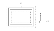
- FIG. 8 shows a display example of an obstacle for which a clearance is set.
- clearances are individually set for the boxes 60, 62, and the support column 64, and a region where the clearances are set is indicated by a two-dot chain line.
- the clearance amount of the box 60 in which the work is accommodated and the box 62 in which the work is placed is smaller than the clearance amount of the column 64 which does not have the recess.
- the boxes 60 and 62 have a recess. Therefore, for example, not only is the clearance set outside the box 60 as shown in FIG. 9A when the box 60 is viewed from the side, but also inside the box 60 as shown in FIG. 9B when the box 60 is viewed from above. Clearance is also set.
- the obstacle may be displayed differently depending on the clearance amount.
- the clearance amount of the boxes 60 and 62 when the clearance amount of the boxes 60 and 62 is smaller than the clearance amount of the support column 64, the colors of the boxes 60 and 62 are different from the color of the support column 64. Thereby, it is possible to easily recognize that different clearance amounts are set.
- the clearance amount set for one obstacle may be set uniformly for other obstacles.
- the clearance amount set on the support column 64 may be set uniformly on the boxes 60 and 62.
- the setting unit 22 may receive an adjustment coefficient for adjusting the clearance amount, and adjust a plurality of clearance amounts based on the received adjustment coefficient.
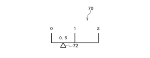
- a reception screen 70 that receives the adjustment coefficient is displayed on the monitor 16.
- the adjustment coefficient can be set in the range of 0 to 2 by performing an operation of sliding the adjustment bar 72 left and right.
- the range in which the adjustment coefficient can be set is not limited to this, and may be set as appropriate.
- the setting unit 22 sets a value obtained by multiplying the clearance amount by the adjustment coefficient as the adjusted clearance amount.
- the adjustment coefficient is set to “1”. Therefore, for example, when the clearance amount of the robot RB and the obstacle is set as shown in FIG. 7, each clearance amount does not change.
- the adjustment coefficient is set to “2”. Therefore, for example, the clearance amount of the box in FIG. 7 doubles to 10 mm, and the clearance amount of the camera stand doubles to 20 mm. Similarly, the other clearance amounts are doubled.
- the adjustment coefficient is set to “0.5”. Therefore, for example, the clearance amount of the box in FIG. 7 is 0.5 times 2.5 mm, and the clearance amount of the camera stand is 0.5 times 5 mm. The other clearance amounts are also 0.5 times.
- the CPU 11 uses the posture information, the position information, the obstacle information, and the specification information acquired in step S100, and the clearance amount set in step S102, and the route relating to the robot RB and the velocity-related route. Information is generated (step S106).
- RRT Rapidly exploring random tree
- RRT * Rapidly exploring random tree
- RRT connect PRM (Probabilistic Roadmap Method)
- STOMP Spochastic Trajectory Optimization for Motion Planninng
- CHOMP Covariant Hamiltonian Optimization for Motion Planning
- EET Exposure/Exploiting Tree
- the CPU 11 determines whether or not the robot RB interferes with the obstacle in the route generated in step S106 based on the route information generated in step S100 and the obstacle information ( Step S108).
- a known interference determination technique for determining the interference between the robot RB and the obstacle is used.
- a known interference determination technique for example, the technique described in JP-A-2002-273675 can be used.
- step S108 When it is determined that the robot RB does not interfere with the obstacle (step S108: NO), the process proceeds to step S110. On the other hand, when the robot RB interferes with the obstacle (step S108: YES), the process proceeds to step S106, and the route is regenerated so that the robot RB does not interfere with the obstacle. Then, the processes of steps S106 and S108 are repeated until the robot RB does not interfere with the obstacle.
- the CPU 11 determines whether or not the route generated in step S106 satisfies a predetermined route condition (step S110).
- the case where the route condition is satisfied is, for example, a case where the route length of the route is equal to or less than a predetermined reference route length.
- the path length is the length of the path from the initial posture generated in step S106 to the target posture.
- the reference route length may be, for example, a value obtained by adding a predetermined margin value to the route length of the route taught by teaching, or by adding a predetermined margin value to the route length of the route when the clearance is not set. It may be a value. This can prevent the path length from becoming too long.
- the route condition may be the case where the operation time of the route is less than or equal to a predetermined reference operation time.
- the operation time of the route is the time that the robot RB moves along the route from the initial posture generated in step S106 to the target posture.
- the reference operation time may be, for example, a value obtained by adding a predetermined margin value to the operation time of the route taught by teaching, or may be a value obtained by adding a predetermined margin value to the operation time of the route when the clearance is not set. It may be a value. This can prevent the operation time of the robot RB from becoming too long.
- the case where the route condition is satisfied may be the case where the route length of the route is equal to or less than the reference route length and the operation time of the route is equal to or less than the reference operation time.
- step S106 if the route generated in step S106 satisfies the predetermined route condition, the process proceeds to step S112. On the other hand, if the route generated in step S106 does not satisfy the predetermined route condition, the process proceeds to step S102 and the clearance amount is reset. That is, the clearance amount is reduced. Then, the processes of steps S102 to S110 are repeated until the generated route satisfies a predetermined route condition.
- step S112 the operation command value is output to the robot RB based on the generated route information.
- the robot RB operates according to the route information.
- the clearance amount is individually set for at least one of the robot RB and the obstacle. As a result, as compared with the case where the clearance amount is uniformly set, it is possible to prevent the success rate of the operation of the robot from decreasing and at the same time prevent the safety of the operation of the robot from decreasing.
- the obstacle information regarding the obstacles is generated based on the captured image captured by the camera 38 illustrated in FIG. 5, for example. You may.
- the camera 38 may be a camera that captures a two-dimensional image or a camera that captures a three-dimensional image.
- the acquisition unit 20 acquires a captured image captured by the camera 38.
- the setting unit 22 generates obstacle information based on the acquired captured image, and sets the clearance amount based on the generated obstacle information.
- a known method such as template matching can be used to generate the obstacle information.
- the clearance amount set in step S102 in FIG. 6 may be adjusted according to at least one of the weight and size of the work. For example, the clearance amount may be increased as the weight of the work increases, and the clearance amount may be decreased as the weight of the work decreases. Further, the clearance amount may increase as the size of the work increases, and the clearance amount may decrease as the size of the work decreases.
- the control target of the robot control device may be a robot that operates on simulation.
- the robot control processing executed by the CPU by reading the software (program) in each of the above embodiments may be executed by various processors other than the CPU.
- a processor a PLD (Programmable Logic Device) whose circuit configuration can be changed after manufacturing an FPGA (Field-Programmable Gate Array) or the like, and a specific processing of performing ASIC (Application Integrated Circuit), etc.
- An example is a dedicated electric circuit, which is a processor having a circuit configuration designed exclusively.
- the robot control process may be executed by one of these various processors, or a combination of two or more processors of the same type or different types (for example, a plurality of FPGAs and a combination of a CPU and an FPGA). Etc.).
- the hardware structure of these various processors is, more specifically, an electric circuit in which circuit elements such as semiconductor elements are combined.
- the mode in which the robot control program is stored (installed) in the storage 14 or the ROM 12 in advance has been described, but the present invention is not limited to this.
- the program may be provided in a recording medium such as CD-ROM (Compact Disk Read Only Memory), DVD-ROM (Digital Versatile Disk Read Only Memory), and USB (Universal Serial Bus) memory. Further, the program may be downloaded from an external device via a network.
- robot control device 20 acquisition unit 22 setting unit 24 route generation unit 26 display control units 30, 60, 62 box 32 shelf 38 camera 40 camera stand 50 clearance amount setting information 64 prop 70 reception screen 72 adjustment bar
Landscapes
- Engineering & Computer Science (AREA)
- Robotics (AREA)
- Mechanical Engineering (AREA)
- Human Computer Interaction (AREA)
- Manipulator (AREA)
- Numerical Control (AREA)
Abstract
La présente invention concerne un générateur d'itinéraire qui comprend : une unité d'acquisition pour acquérir des informations de posture se rapportant à la posture initiale et à la posture cible d'un robot, des informations de position se rapportant à la position du robot, des informations d'obstacle comprenant la ou les positions d'un ou de plusieurs obstacles présents dans une zone d'interférence avec le robot, et des informations de spécification se rapportant à des spécifications comprenant une forme de robot ; une unité de réglage pour régler un jeu, qui représente la quantité de jeu pour éviter une interférence, pour le robot et/ou un obstacle présent dans la zone d'interférence avec le robot sur la base de la relation de position entre le robot et l'obstacle ; et une unité de génération d'itinéraire pour générer des informations d'itinéraire se rapportant à l'itinéraire du robot sur la base de la posture initiale et de la posture cible du robot, de la position du robot, de la position de l'obstacle, de la forme du robot et du jeu réglé par l'unité de réglage.
Priority Applications (3)
| Application Number | Priority Date | Filing Date | Title |
|---|---|---|---|
| CN201980059699.XA CN112672857A (zh) | 2019-01-15 | 2019-11-27 | 路径生成装置、路径生成方法及路径生成程序 |
| US17/275,315 US20210260763A1 (en) | 2019-01-15 | 2019-11-27 | Path Generation Device, Path Generation Method, and Recording Medium Storing Path Generation Program |
| EP19910467.0A EP3912768A4 (fr) | 2019-01-15 | 2019-11-27 | Générateur d'itinéraire, procédé de génération d'itinéraire et programme de génération d'itinéraire |
Applications Claiming Priority (2)
| Application Number | Priority Date | Filing Date | Title |
|---|---|---|---|
| JP2019-004311 | 2019-01-15 | ||
| JP2019004311A JP7147571B2 (ja) | 2019-01-15 | 2019-01-15 | 経路生成装置、経路生成方法、及び経路生成プログラム |
Publications (1)
| Publication Number | Publication Date |
|---|---|
| WO2020149021A1 true WO2020149021A1 (fr) | 2020-07-23 |
Family
ID=71614212
Family Applications (1)
| Application Number | Title | Priority Date | Filing Date |
|---|---|---|---|
| PCT/JP2019/046326 WO2020149021A1 (fr) | 2019-01-15 | 2019-11-27 | Générateur d'itinéraire, procédé de génération d'itinéraire et programme de génération d'itinéraire |
Country Status (5)
| Country | Link |
|---|---|
| US (1) | US20210260763A1 (fr) |
| EP (1) | EP3912768A4 (fr) |
| JP (1) | JP7147571B2 (fr) |
| CN (1) | CN112672857A (fr) |
| WO (1) | WO2020149021A1 (fr) |
Cited By (2)
| Publication number | Priority date | Publication date | Assignee | Title |
|---|---|---|---|---|
| CN113568435A (zh) * | 2021-09-24 | 2021-10-29 | 深圳火眼智能有限公司 | 一种基于无人机自主飞行态势感知趋势的分析方法与系统 |
| WO2023162164A1 (fr) * | 2022-02-25 | 2023-08-31 | 三菱電機株式会社 | Dispositif de support d'enseignement, système de travail, procédé de support d'enseignement et programme de support d'enseignement |
Families Citing this family (3)
| Publication number | Priority date | Publication date | Assignee | Title |
|---|---|---|---|---|
| WO2020161910A1 (fr) * | 2019-02-08 | 2020-08-13 | 日本電気株式会社 | Dispositif de commande, procédé de commande et support d'enregistrement |
| JP2022181974A (ja) * | 2021-05-27 | 2022-12-08 | 株式会社ジャノメ | 経路教示データ作成装置及び経路教示データ作成方法並びにプログラム |
| CN113448667B (zh) * | 2021-06-09 | 2023-08-01 | 绿盟科技集团股份有限公司 | 一种生成展示关系图的方法及装置 |
Citations (12)
| Publication number | Priority date | Publication date | Assignee | Title |
|---|---|---|---|---|
| JPH05204428A (ja) * | 1992-01-28 | 1993-08-13 | Fanuc Ltd | 複数ロボット制御方式 |
| JPH05250023A (ja) * | 1991-10-23 | 1993-09-28 | Sanyo Electric Co Ltd | ロボットマニピュレータの経路自動生成法 |
| JPH0934524A (ja) * | 1995-07-18 | 1997-02-07 | Kobe Steel Ltd | ロボットマニピュレータの移動経路の自動生成方法 |
| JP2002273675A (ja) | 2001-03-16 | 2002-09-25 | Kawasaki Heavy Ind Ltd | ロボット制御方法およびロボット制御システム |
| JP2003280710A (ja) * | 2002-03-20 | 2003-10-02 | Japan Atom Energy Res Inst | ロボットハンドの作業軌道の生成と制御方法 |
| JP2007313592A (ja) * | 2006-05-24 | 2007-12-06 | Toyota Motor Corp | 経路作成装置及び経路作成方法 |
| JP2009032189A (ja) * | 2007-07-30 | 2009-02-12 | Toyota Motor Corp | ロボットの動作経路生成装置 |
| JP2009233757A (ja) * | 2008-03-25 | 2009-10-15 | Ihi Corp | ロボット装置の制御方法及びロボット装置 |
| JP2015160277A (ja) | 2014-02-27 | 2015-09-07 | ファナック株式会社 | ロボットの動作経路を生成するロボットシミュレーション装置 |
| JP2016078184A (ja) * | 2014-10-17 | 2016-05-16 | ファナック株式会社 | ロボットの干渉領域設定装置 |
| JP2018134703A (ja) * | 2017-02-21 | 2018-08-30 | 株式会社安川電機 | ロボットシミュレータ、ロボットシステム及びシミュレーション方法 |
| US20180281191A1 (en) * | 2017-03-30 | 2018-10-04 | Brain Corporation | Systems and methods for robotic path planning |
Family Cites Families (14)
| Publication number | Priority date | Publication date | Assignee | Title |
|---|---|---|---|---|
| US9468501B2 (en) | 1999-09-17 | 2016-10-18 | Intuitive Surgical Operations, Inc. | Systems and methods for using the null space to emphasize manipulator joint motion anisotropically |
| US6678582B2 (en) * | 2002-05-30 | 2004-01-13 | Kuka Roboter Gmbh | Method and control device for avoiding collisions between cooperating robots |
| JP5089533B2 (ja) * | 2008-08-28 | 2012-12-05 | 株式会社神戸製鋼所 | ロボットの干渉回避方法及びロボットシステム |
| US9993222B2 (en) * | 2014-02-05 | 2018-06-12 | Intuitive Surgical Operations, Inc. | System and method for dynamic virtual collision objects |
| JP6378783B2 (ja) * | 2014-12-25 | 2018-08-22 | 川崎重工業株式会社 | アーム型のロボットの障害物自動回避方法及び制御装置 |
| JP6755724B2 (ja) * | 2016-06-20 | 2020-09-16 | キヤノン株式会社 | 制御方法、ロボットシステム、および物品の製造方法 |
| US9981383B1 (en) * | 2016-08-02 | 2018-05-29 | X Development Llc | Real-time trajectory generation for actuators of a robot to reduce chance of collision with obstacle(s) |
| CN109310473B (zh) * | 2016-09-19 | 2023-02-17 | 直观外科手术操作公司 | 用于可控臂的基部定位系统以及相关方法 |
| JP6457469B2 (ja) * | 2016-12-08 | 2019-01-23 | ファナック株式会社 | 移動ロボットの干渉領域設定装置 |
| JP6506342B2 (ja) * | 2017-04-26 | 2019-04-24 | 株式会社安川電機 | ロボット |
| KR102024092B1 (ko) * | 2017-07-12 | 2019-09-23 | 엘지전자 주식회사 | 이동 로봇 시스템 및 그 제어방법 |
| US10682774B2 (en) * | 2017-12-12 | 2020-06-16 | X Development Llc | Sensorized robotic gripping device |
| US10606269B2 (en) * | 2017-12-19 | 2020-03-31 | X Development Llc | Semantic obstacle recognition for path planning |
| WO2019237351A1 (fr) * | 2018-06-15 | 2019-12-19 | 深圳前海达闼云端智能科技有限公司 | Procédé et appareil de commande de déplacement de robot, support de stockage et robot |
-
2019
- 2019-01-15 JP JP2019004311A patent/JP7147571B2/ja active Active
- 2019-11-27 US US17/275,315 patent/US20210260763A1/en active Pending
- 2019-11-27 EP EP19910467.0A patent/EP3912768A4/fr active Pending
- 2019-11-27 WO PCT/JP2019/046326 patent/WO2020149021A1/fr unknown
- 2019-11-27 CN CN201980059699.XA patent/CN112672857A/zh active Pending
Patent Citations (12)
| Publication number | Priority date | Publication date | Assignee | Title |
|---|---|---|---|---|
| JPH05250023A (ja) * | 1991-10-23 | 1993-09-28 | Sanyo Electric Co Ltd | ロボットマニピュレータの経路自動生成法 |
| JPH05204428A (ja) * | 1992-01-28 | 1993-08-13 | Fanuc Ltd | 複数ロボット制御方式 |
| JPH0934524A (ja) * | 1995-07-18 | 1997-02-07 | Kobe Steel Ltd | ロボットマニピュレータの移動経路の自動生成方法 |
| JP2002273675A (ja) | 2001-03-16 | 2002-09-25 | Kawasaki Heavy Ind Ltd | ロボット制御方法およびロボット制御システム |
| JP2003280710A (ja) * | 2002-03-20 | 2003-10-02 | Japan Atom Energy Res Inst | ロボットハンドの作業軌道の生成と制御方法 |
| JP2007313592A (ja) * | 2006-05-24 | 2007-12-06 | Toyota Motor Corp | 経路作成装置及び経路作成方法 |
| JP2009032189A (ja) * | 2007-07-30 | 2009-02-12 | Toyota Motor Corp | ロボットの動作経路生成装置 |
| JP2009233757A (ja) * | 2008-03-25 | 2009-10-15 | Ihi Corp | ロボット装置の制御方法及びロボット装置 |
| JP2015160277A (ja) | 2014-02-27 | 2015-09-07 | ファナック株式会社 | ロボットの動作経路を生成するロボットシミュレーション装置 |
| JP2016078184A (ja) * | 2014-10-17 | 2016-05-16 | ファナック株式会社 | ロボットの干渉領域設定装置 |
| JP2018134703A (ja) * | 2017-02-21 | 2018-08-30 | 株式会社安川電機 | ロボットシミュレータ、ロボットシステム及びシミュレーション方法 |
| US20180281191A1 (en) * | 2017-03-30 | 2018-10-04 | Brain Corporation | Systems and methods for robotic path planning |
Non-Patent Citations (1)
| Title |
|---|
| See also references of EP3912768A4 |
Cited By (2)
| Publication number | Priority date | Publication date | Assignee | Title |
|---|---|---|---|---|
| CN113568435A (zh) * | 2021-09-24 | 2021-10-29 | 深圳火眼智能有限公司 | 一种基于无人机自主飞行态势感知趋势的分析方法与系统 |
| WO2023162164A1 (fr) * | 2022-02-25 | 2023-08-31 | 三菱電機株式会社 | Dispositif de support d'enseignement, système de travail, procédé de support d'enseignement et programme de support d'enseignement |
Also Published As
| Publication number | Publication date |
|---|---|
| EP3912768A1 (fr) | 2021-11-24 |
| JP2020110885A (ja) | 2020-07-27 |
| CN112672857A (zh) | 2021-04-16 |
| EP3912768A4 (fr) | 2022-09-28 |
| JP7147571B2 (ja) | 2022-10-05 |
| US20210260763A1 (en) | 2021-08-26 |
Similar Documents
| Publication | Publication Date | Title |
|---|---|---|
| WO2020149021A1 (fr) | Générateur d'itinéraire, procédé de génération d'itinéraire et programme de génération d'itinéraire | |
| JP6807949B2 (ja) | 干渉回避装置 | |
| US9827675B2 (en) | Collision avoidance method, control device, and program | |
| EP3578322A1 (fr) | Dispositif de génération de trajet de robot et système de robot | |
| US11090807B2 (en) | Motion generation method, motion generation device, system, and computer program | |
| EP3581342A1 (fr) | Appareil, procédé et programme de planification de trajet | |
| JP2020032481A (ja) | ロボット制御装置、ロボット装置、ロボット制御のパラメータ調整方法、およびプログラム | |
| JP2014180704A (ja) | ロボットピッキングシステム及び被加工物の製造方法 | |
| JP7124440B2 (ja) | ロボット制御装置およびロボットシステム | |
| WO2020012710A1 (fr) | Dispositif de commande de manipulateur, procédé de commande de manipulateur et programme de commande de manipulateur | |
| US20180154520A1 (en) | Control device, robot, and robot system | |
| JP5513661B2 (ja) | 付加軸付きロボットのオフラインプログラム作成装置 | |
| US20240066705A1 (en) | Interference Evaluation Device, Method, and Program | |
| US11597083B2 (en) | Robot apparatus, robot system, control method of robot apparatus, product manufacturing method using robot apparatus, and storage medium | |
| JP6697544B2 (ja) | 最適化装置及びそれを備えた垂直型多関節ロボット | |
| JP5474739B2 (ja) | 干渉検出方法及び干渉検出装置 | |
| WO2020149020A1 (fr) | Dispositif de commande de robot, procédé de commande de robot et programme de commande de robot | |
| US11697206B2 (en) | Acceleration adjustment apparatus and non-transitory computer-readable storage medium storing an acceleration adjustment program | |
| JP2021186929A (ja) | 多軸ロボットの制御方法 | |
| JP2000112510A (ja) | ロボットの教示方法及びその装置 | |
| WO2023203635A1 (fr) | Dispositif de simulation permettant de calculer l'état de fonctionnement d'un dispositif de robot | |
| JP6932618B2 (ja) | ロボット教示方法、ロボット教示装置、ロボットシステム、プログラム及び記録媒体 | |
| US20230398687A1 (en) | Method for generating movement route of robot, movement route generation apparatus, robot system, and program | |
| US20210031369A1 (en) | Apparatus, robot control device, robot system, and method of setting robot coordinate system | |
| JP2020163499A (ja) | 物体検出方法、物体検出装置およびロボットシステム |
Legal Events
| Date | Code | Title | Description |
|---|---|---|---|
| 121 | Ep: the epo has been informed by wipo that ep was designated in this application |
Ref document number: 19910467 Country of ref document: EP Kind code of ref document: A1 |
|
| NENP | Non-entry into the national phase |
Ref country code: DE |
|
| ENP | Entry into the national phase |
Ref document number: 2019910467 Country of ref document: EP Effective date: 20210816 |