WO2020138173A1 - シート部材の製造方法及びシート部材の製造装置 - Google Patents
シート部材の製造方法及びシート部材の製造装置 Download PDFInfo
- Publication number
- WO2020138173A1 WO2020138173A1 PCT/JP2019/050834 JP2019050834W WO2020138173A1 WO 2020138173 A1 WO2020138173 A1 WO 2020138173A1 JP 2019050834 W JP2019050834 W JP 2019050834W WO 2020138173 A1 WO2020138173 A1 WO 2020138173A1
- Authority
- WO
- WIPO (PCT)
- Prior art keywords
- fiber assembly
- woven fabric
- rotating body
- sheet member
- manufacturing
- Prior art date
- Legal status (The legal status is an assumption and is not a legal conclusion. Google has not performed a legal analysis and makes no representation as to the accuracy of the status listed.)
- Ceased
Links
Images




Classifications
-
- A—HUMAN NECESSITIES
- A61—MEDICAL OR VETERINARY SCIENCE; HYGIENE
- A61F—FILTERS IMPLANTABLE INTO BLOOD VESSELS; PROSTHESES; DEVICES PROVIDING PATENCY TO, OR PREVENTING COLLAPSING OF, TUBULAR STRUCTURES OF THE BODY, e.g. STENTS; ORTHOPAEDIC, NURSING OR CONTRACEPTIVE DEVICES; FOMENTATION; TREATMENT OR PROTECTION OF EYES OR EARS; BANDAGES, DRESSINGS OR ABSORBENT PADS; FIRST-AID KITS
- A61F13/00—Bandages or dressings; Absorbent pads
- A61F13/15—Absorbent pads, e.g. sanitary towels, swabs or tampons for external or internal application to the body; Supporting or fastening means therefor; Tampon applicators
- A61F13/51—Absorbent pads, e.g. sanitary towels, swabs or tampons for external or internal application to the body; Supporting or fastening means therefor; Tampon applicators characterised by the outer layers of the pads
- A61F13/511—Topsheet, i.e. the permeable cover or layer facing the skin
-
- D—TEXTILES; PAPER
- D04—BRAIDING; LACE-MAKING; KNITTING; TRIMMINGS; NON-WOVEN FABRICS
- D04H—MAKING TEXTILE FABRICS, e.g. FROM FIBRES OR FILAMENTARY MATERIAL; FABRICS MADE BY SUCH PROCESSES OR APPARATUS, e.g. FELTS, NON-WOVEN FABRICS; COTTON-WOOL; WADDING ; NON-WOVEN FABRICS FROM STAPLE FIBRES, FILAMENTS OR YARNS, BONDED WITH AT LEAST ONE WEB-LIKE MATERIAL DURING THEIR CONSOLIDATION
- D04H1/00—Non-woven fabrics formed wholly or mainly of staple fibres or like relatively short fibres
- D04H1/40—Non-woven fabrics formed wholly or mainly of staple fibres or like relatively short fibres from fleeces or layers composed of fibres without existing or potential cohesive properties
- D04H1/44—Non-woven fabrics formed wholly or mainly of staple fibres or like relatively short fibres from fleeces or layers composed of fibres without existing or potential cohesive properties the fleeces or layers being consolidated by mechanical means, e.g. by rolling
- D04H1/46—Non-woven fabrics formed wholly or mainly of staple fibres or like relatively short fibres from fleeces or layers composed of fibres without existing or potential cohesive properties the fleeces or layers being consolidated by mechanical means, e.g. by rolling by needling or like operations to cause entanglement of fibres
- D04H1/498—Non-woven fabrics formed wholly or mainly of staple fibres or like relatively short fibres from fleeces or layers composed of fibres without existing or potential cohesive properties the fleeces or layers being consolidated by mechanical means, e.g. by rolling by needling or like operations to cause entanglement of fibres entanglement of layered webs
-
- D—TEXTILES; PAPER
- D04—BRAIDING; LACE-MAKING; KNITTING; TRIMMINGS; NON-WOVEN FABRICS
- D04H—MAKING TEXTILE FABRICS, e.g. FROM FIBRES OR FILAMENTARY MATERIAL; FABRICS MADE BY SUCH PROCESSES OR APPARATUS, e.g. FELTS, NON-WOVEN FABRICS; COTTON-WOOL; WADDING ; NON-WOVEN FABRICS FROM STAPLE FIBRES, FILAMENTS OR YARNS, BONDED WITH AT LEAST ONE WEB-LIKE MATERIAL DURING THEIR CONSOLIDATION
- D04H1/00—Non-woven fabrics formed wholly or mainly of staple fibres or like relatively short fibres
- D04H1/70—Non-woven fabrics formed wholly or mainly of staple fibres or like relatively short fibres characterised by the method of forming fleeces or layers, e.g. reorientation of fibres
- D04H1/72—Non-woven fabrics formed wholly or mainly of staple fibres or like relatively short fibres characterised by the method of forming fleeces or layers, e.g. reorientation of fibres the fibres being randomly arranged
- D04H1/732—Non-woven fabrics formed wholly or mainly of staple fibres or like relatively short fibres characterised by the method of forming fleeces or layers, e.g. reorientation of fibres the fibres being randomly arranged by fluid current, e.g. air-lay
-
- D—TEXTILES; PAPER
- D06—TREATMENT OF TEXTILES OR THE LIKE; LAUNDERING; FLEXIBLE MATERIALS NOT OTHERWISE PROVIDED FOR
- D06C—FINISHING, DRESSING, TENTERING OR STRETCHING TEXTILE FABRICS
- D06C29/00—Finishing or dressing, of textile fabrics, not provided for in the preceding groups
Definitions
- the present invention relates to a sheet member manufacturing method and a sheet member manufacturing apparatus.
- Patent Document 1 discloses that a non-woven fabric composite low-density fabric in which a woven fabric and a non-woven fabric are entangled is used in order to soften the texture of absorbent articles such as sanitary napkins and disposable diapers.
- the woven fabric since the woven fabric has a fixed shape, it can be stably transported at the time of transportation and the like, and the fibers constituting the non-woven fabric to be entangled with the woven fabric. Is a light material and does not have a standard size, so it is susceptible to external influences during transportation. Therefore, the fibers constituting the non-woven fabric may not be stably transported as compared with the woven fabric, and the fibers constituting the non-woven fabric to be entangled with the woven fabric may not be uniform.
- the present invention has been made in view of the above problems, and an object thereof is to convey a fiber assembly in a more stable state to manufacture a sheet member.
- a main invention for achieving the above object is a method for producing a sheet member for an absorbent article having a woven fabric, and a fiber assembly in a state of being entangled with the woven fabric, and at least one of the continuous woven fabrics.
- the method for manufacturing a sheet member is characterized by the following. Other features of the present invention will become apparent from the description of this specification and the accompanying drawings.
- the fiber assembly can be transported in a more stable state.
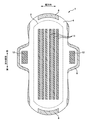
- FIG. 1 is a plan view of the sanitary napkin 1 viewed from the skin side.
- FIG. 2 is a plan view of the sanitary napkin 1 viewed from the non-skin side.
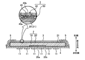
- FIG. 3 is a sectional view taken along the line XX in FIG.
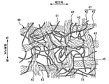
- FIG. 4 is a partially enlarged view of the topsheet 3.
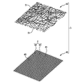
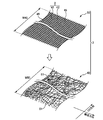
- FIG. 5 is a diagram showing a state in which the topsheet 3 is separated into the woven fabric 40 and the fiber assembly 50.
- FIG. 6 is a diagram schematically showing a part of the manufacturing apparatus 100 used in the method for manufacturing the sheet member 70 of the first embodiment.
- FIG. 7 is a diagram schematically showing the woven fabric 40 and the fiber assembly 50 in the first step.
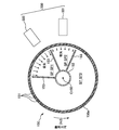
- FIG. 8 is a diagram schematically showing a cross section of the first rotating body 150.
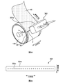
- FIG. 9A is a diagram schematically showing the ejection nozzle 302.
- FIG. 9B is a diagram schematically showing a configuration example of the nozzle holes of the injection nozzle 302.
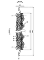
- FIG. 10 is a diagram schematically showing a cross section in the CD direction of the sheet 60 at B in FIG.
- FIG. 11 is a figure which shows typically some manufacturing apparatuses 101 used for the manufacturing method of the sheet member 70 of 2nd Embodiment.
- FIG. 12 is a diagram schematically showing a part of the manufacturing apparatus 102 used in the method for manufacturing the sheet member 70 according to the third embodiment.
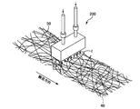
- FIG. 13 is a diagram schematically showing the water supply device 200.
- a method for manufacturing a sheet member for an absorbent article comprising a woven fabric and a fiber assembly in a state of being entangled with the woven fabric, wherein the fiber assembly is arranged on at least one surface side of the continuous woven fabric. And a entanglement for ejecting a fluid toward the woven fabric and the fiber aggregate to convey the woven fabric and the fiber aggregate after the arranging step to entangle the fiber aggregate with the woven fabric.
- the fiber assembly can be transported in a more stable state.
- a method of manufacturing such a sheet member wherein in the entanglement step, the fiber assembly is transported at a transport speed using a transport mechanism, and the fiber is transported toward the transport mechanism using another transport mechanism. It is preferable that the aggregate is transported at another transport speed, and the certain transport speed is equal to or higher than the other transport speed.
- a method of manufacturing such a sheet member wherein in the entanglement step, a fluid is ejected a plurality of times at different positions in the carrying direction toward the woven fabric and the fiber assembly, and a fluid is jetted upstream in the carrying direction. It is desirable that the pressure is less than or equal to the pressure of the fluid ejected on the downstream side in the transport direction.
- the fibers of the fiber assembly can be entangled with the woven fabric while reducing the risk of being blown out by the jetted fluid.
- the fiber assembly can be transported in a more stable state.
- the woven fabric is brought into contact with the peripheral surface of the rotating body and conveyed in the entanglement step.
- the fiber assembly can be entangled while being transported in a more stable state.
- the rotating body is a first rotating body, and a second rotating body different from the first rotating body is provided, and the first rotating body is provided.
- the at least one of the woven fabric and the fiber aggregate is brought into contact with the peripheral surface of the second rotating body and conveyed, and the peripheral speed of the second rotating body is equal to or higher than the peripheral speed of the first rotating body. Is desirable.
- the second rotating body includes a suction mechanism, and a fluid is jetted from the outer side to the inner side in the radial direction of the second rotating body to entangle the fiber assembly with the woven fabric. It is desirable to let
- a method of manufacturing such a sheet member wherein at least the fiber assembly is conveyed to the rotating body by using a conveying conveyor, and a conveying surface of the conveying conveyor is provided below a rotation center of the rotating body. It is desirable that the method further include a passing step in which the fiber assembly passes through the closest position between the rotary body and the transport conveyor between the transport by the transport conveyor and the transport by the rotary body.
- a method of manufacturing such a sheet member wherein in the transport by the transport conveyor, the transport conveyor does not transport the fabric, and before the transport by the rotating body, a supplying step of supplying the fabric to the rotating body. It is desirable to have.
- the supply rotating body for supplying the woven fabric supplies the woven fabric with a constant tension of the woven fabric.
- the peripheral speed of the supply rotating body is equal to the peripheral speed of the rotating body, and the peripheral speed of the rotating body is equal to or higher than the moving speed of the transport conveyor. desirable.
- the transporting surface of the transporting conveyor has the same height as the rotation center of the rotating body, Alternatively, it is preferable that the fiber assembly is provided at a position higher than the center of rotation, and immediately after the start of conveyance using the rotating body, the fiber assembly is conveyed upward along the rotation direction of the rotating body.
- the woven fabric and the fiber assembly can be transported in a more stable state.
- a method for manufacturing such a sheet member wherein in the entanglement step, the woven fabric and the fiber assembly are conveyed by using one of the rotating bodies, and after the conveying by the rotating body, the woven fabric is formed by using a downstream side conveyor. It is preferable that the fiber aggregate is conveyed and the conveying speed of the downstream side conveyer is equal to or higher than the peripheral speed of the rotating body.
- the downstream side conveyor includes a suction mechanism, and while conveying the woven fabric and the fiber assembly by using the downstream side conveyor, the downstream side conveyor is directed toward the woven fabric and the fiber assembly. It is desirable to jet a fluid to further entangle the fiber assembly with the woven fabric.
- a manufacturing apparatus for a sheet member for an absorbent article comprising: a woven fabric; and a fiber assembly in a state of being entangled with the woven fabric, wherein the fiber assembly is disposed on at least one step side of the continuous woven fabric. After disposing the arranging portion and the fiber assembly, while transporting the woven fabric and the fiber aggregate, a fluid is jetted toward the woven fabric and the fiber aggregate, and the fiber aggregate is attached to the woven fabric. And a entanglement portion to be entangled, wherein the maximum length of the fiber assembly is equal to or less than the length of the woven material in the CD direction orthogonal to the transport direction of the woven material and the fiber assembly. It is an apparatus for manufacturing a sheet member.
- the fiber assembly can be transported in a more stable state.
- a sanitary napkin as an example, but the present invention is not limited to this.
- other absorbent articles such as a vaginal discharge sheet, a urine absorbing pad, and a disposable diaper. Can also be applied to.
- FIG. 1 is a plan view of the sanitary napkin 1 (hereinafter also referred to as “napkin 1”) as seen from the skin side.
- FIG. 2 is a plan view of the sanitary napkin 1 viewed from the non-skin side.
- FIG. 3 is a sectional view taken along the line XX in FIG.
- the napkin 1 has a front-back direction, a width direction, and a thickness direction that are orthogonal to each other. In the front-rear direction, the side that contacts the lower abdomen of the wearer is the front side, and the side that contacts the buttocks is the rear side. In the thickness direction, the side in contact with the wearer is called the skin side, and the opposite side is called the non-skin side.
- the napkin 1 includes a pair of side sheets 5, a top sheet 3, an absorber 2, and a back sheet 4, which are laminated in this order from the skin side in the thickness direction. ing.
- the topsheet 3 and the absorber 2 are joined to each other by a known joining means such as a hot melt adhesive.
- the top sheet 3 and the back sheet 4 have a plane size larger than that of the absorber 2 and cover the entire plane of the absorber 2.
- the topsheet 3, the backsheet 4, and the sidesheet 5 that are laminated on each other are joined to each other via an outer peripheral seal portion 8 along the outer peripheral edge of the napkin 1.
- the pair of side sheets 5 are provided on both sides in the width direction, are arranged on the skin side of the top sheet 3 along the front-rear direction, and are joined to the top sheet 3 by a known adhesion means or welding means.
- the napkin 1 has a pair of wing portions 6 extending from the central region of the napkin 1 in the front-rear direction to both outer sides in the width direction.
- the wing portion 6 is formed by the side sheet 5 and the back sheet 4 extending outward from both side portions of the top sheet 3 in the width direction.
- the napkin 1 may not have the wing portion 6.
- An adhesive area 11 to which an adhesive is applied is provided on the non-skin side surface of the napkin 1 (non-skin side surface of the back sheet 4).
- the adhesive region 11 is attached to the skin side surface of underwear or the like, and the napkin 1 is fixed to the underwear or the like.
- the shape and number of the adhesive areas 11 can be arbitrarily changed.
- each wing portion 6 (the non-skin side surface of the back sheet 4) is provided with a wing portion adhesive area 12.
- the wing portion adhesive region 12 is attached to a non-skin side surface such as underwear so that the napkin 1 is fixed to the underwear or the like.
- the shape and number of the wing portion adhesive regions 12 can be arbitrarily changed.
- the topsheet 3 is liquid-permeable and is composed of the fabric 40 and the fiber assembly 50.
- the back sheet 4 can be formed of a liquid-impermeable and moisture-permeable plastic film, a liquid-impermeable non-woven fabric, a laminated sheet thereof, or the like.
- the absorbent body 2 is a member that absorbs excrement such as menstrual blood and holds it inside, and has an absorbent core 10 that absorbs liquid and a liquid-permeable core wrap sheet 20 that covers the entire absorbent core 10.
- the absorbent core 10 is formed by adding a liquid-absorbent granular material such as a super-absorbent polymer (so-called SAP) to a pulp fiber or a cellulosic absorbent fiber, which is a liquid-absorbent fiber, and molding it into a predetermined shape.
- SAP super-absorbent polymer
- the core wrap sheet 20 is a liquid-permeable sheet, and can be exemplified by a tissue, airlaid, or the like.
- FIG. 4 is a partially enlarged view of the topsheet 3 viewed from the skin side
- FIG. 5 is a view showing a state where the topsheet 3 is separated into a woven fabric 40 and a fiber assembly 50.
- the surface sheet 3 is a sheet member in which the woven fabric 40 and the fibers of the fiber assembly 50 are intertwined with each other (the woven fabric 40 and the fiber assembly 50 are entangled) and integrated. is there.
- a method for manufacturing the sheet member 70 in which the woven fabric 40 and the fiber assembly 50 are entangled will be described later.
- the fabric 40 is composed of constituent threads 41 woven in a lattice pattern.
- the constituent yarn 41 has a plurality of warp yarns 42 and a plurality of weft yarns 43 intersecting with the warp yarns 42, and is a through-hole surrounded by the warp yarns 42 and the weft yarns 43 formed by intersecting each other in the thickness direction.
- a plurality of weaves 45, which are regions, are formed.
- the constituent yarn 41 of the woven fabric 40 is a twisted yarn formed by twisting a raw yarn made of cotton yarn (cotton fiber).
- the material of the raw yarn in addition to cotton fibers, natural cellulose fibers such as hemp and pulp fibers, regenerated cellulose fibers such as rayon, and cellulosic fibers such as semisynthetic cellulose fibers such as acetate are preferably used.
- a yarn having a thickness of 10 to 100 cotton count is preferable.
- the weave of the woven fabric 40 is not limited to a plain weave woven in a lattice shape, and a known weave such as a twill weave, a satin weave, and a entangled weave can be appropriately adopted.
- the fiber assembly 50 is a fiber formed by a known method such as a spunbonding method using long fibers or a short-fiber carding in a certain direction by a card machine to arrange the fibers to form a web. It is an aggregate and is in a state of a pre-stage which is formed into a nonwoven fabric. Further, the fiber assembly 50 is formed from the constituent fibers 51 containing hydrophilic fibers.
- the constituent fiber 51 is a soft and light material, and is an irregularly gathered aggregate. Examples of hydrophilic fibers include regenerated cellulose fibers such as rayon and fibril rayon, natural cellulose fibers such as cotton and crushed pulp, and semisynthetic cellulose such as acetate.
- the fiber assembly 50 is not limited to the fiber assembly 50 formed by a card method using a card machine, and a fiber assembly 50 formed by an airlaid method, a wet method, a spunbond method, a meltblown method, or the like may be used.
- the fiber density of the fiber assembly 50 is, for example, 2.8 to 3.5 ⁇ 10 ⁇ 3 g/cm 3
- the basis weight (weight per unit area) is, for example, 20 to 70 g/m 2 . ..
- the thickness of the fiber assembly 50 is, for example, 7 to 20 mm
- the fiber length of the fiber assembly 50 is, for example, 1 to 100 mm.
- the fineness of the fiber assembly 50 is, for example, 0.1 to 6 dtex.
- the manufacturing method of the sheet member 70 of 1st Embodiment> The woven fabric 40 in a continuous state and the fiber assembly 50 manufactured by a fiber assembly manufacturing apparatus (not shown) are entangled and integrated with each other to manufacture the sheet member 70 in a continuous state, and the sheet in a continuous state.
- the topsheet 3 is formed by performing a cutting process for forming the member 70 into a predetermined shape.
- the fabric 40 and the sheet member 70 will be described as being in a continuous state.
- FIG. 6 is a diagram schematically showing a part of the manufacturing apparatus 100 used in the method for manufacturing the sheet member 70 according to the first embodiment.
- the manufacturing apparatus 100 is an apparatus for manufacturing the sheet member 70 in which the fiber assembly 50 and the fabric 40 are entangled and integrated.
- the manufacturing apparatus 100 includes an upstream transfer device 130, a first rotary body 150 and a first injection device 300, a second rotary body 160 and a second injection device 400, a downstream transfer device 140, and a dehydrator 250 from the upstream side in the transfer direction.
- a cutting device 500 is provided.
- the manufacturing apparatus 100 conveys the woven fabric 40 and the fiber aggregate 50 in the conveyance direction, and a direction orthogonal to the conveyance direction is referred to as a “CD direction”.
- the first carrying step is a step of carrying at least the fiber assembly 50 by using the upstream carrying device 130.
- the upstream side transport device 130 includes an upstream side transport belt 130a (also referred to as a “transport conveyor”).
- the upstream side transport belt 130a is a transport unit that transports the fabric 40 and the fiber assembly 50 along a predetermined transport path.
- the fiber assembly 50 is placed in contact with the upstream side conveyor belt 130a, and the fabric 40 is further placed thereon, that is, on the lower surface side of the fabric 40 on the upstream side conveyor belt 130a.
- the fiber aggregate 50 is conveyed in the conveying direction with the fiber aggregate 50 arranged.
- the step of arranging the fiber assembly 50 on the side of at least one surface of the woven fabric 40 is also referred to as “arrangement step”.
- FIG. 7 is a diagram schematically showing the woven fabric 40 and the fiber assembly 50 in the first step. In FIG. 7, for convenience, the woven fabric 40 and the fiber assembly 50 are shown in a separated state, but the woven fabric 40 is superposed from above the fiber assembly 50 in the first conveying step. The woven fabric 40 and the fiber aggregate 50 in FIG.
- the length of the fiber assembly 50 in the CD direction is the maximum length of the fiber assembly 50 in the CD direction.
- “the length of the fiber assembly 50 in the CD direction” means the maximum length of the fiber assembly 50 in the CD direction.
- the fiber assembly 50 When the upstream-side transport belt 130a is viewed in a plan view, the fiber assembly 50 is transported while being covered with the fabric 40 over substantially the entire area. Since the fiber assembly 50 is a soft and light material, it is easily affected by the surrounding conditions and the environment, and the transport speed changes, and the transported fibers become uneven. If the length of the woven fabric 40 in the CD direction (W40) is made shorter than the length of the fiber assembly 50 in the CD direction (W50) (W40 ⁇ W50), the fiber assembly placed on the upstream side conveyor belt 130a. The body 50 has a region in which the fabric 40 is placed on the fiber assembly 50 and a region in which the fabric 40 is not placed on the fiber assembly 50.
- the fiber assembly 50 in the region where the fabric 40 is placed is covered with the fabric 40, so that the degree of freedom is limited.
- the degree of freedom of the fiber assembly 50 in the region where the fabric 40 is not placed is not limited, and thus the fibers of the fiber assembly 50 may move. That is, the fiber density of the fiber assembly 50 may change or the amount of fibers transported may change between the area where the fibers of the fiber assembly 50 are hard to move and the area where the fibers of the fiber assembly 50 are easy to move.
- the fiber aggregate 50 is conveyed in a state in which substantially the entire area of the fiber aggregate 50 is covered with the woven fabric 40, it becomes easy to convey the fiber aggregate 50 in the same stable state in almost the entire area of the fiber aggregate 50.
- the fibers can be easily made uniform. From the first carrying step to before the cutting process in the cutting step, the fabric 40 is carried while maintaining the relationship that the CD-direction length W40 of the fabric 40 is longer than the CD-direction length W50 of the fiber assembly 50.
- the transport surface of the upstream transport belt 130a is provided below the center C150 of the first rotary body 150, and the first rotary body 150 is disposed above the upstream transport device 130.
- the upstream side conveyor belt 130a and the outer peripheral surface 150a of the first rotating body 150 have a portion facing each other.
- the portion where the upstream-side transport belt 130a and the outer peripheral surface 150a of the first rotary body 150 face each other is the closest position between the upstream-side transport device 130 and the first rotary body 150.
- the second rotary body 160 is arranged above the first rotary body 150.
- the second transporting step is a step of further transporting the fiber assembly 50 and the woven fabric 40 transported in the first transporting step by the rotation of the first rotating body 150, and entanglement the fibers of the fiber assembly 50 with the woven fabric 40. is there.
- the step of intertwining the fibers of the fiber assembly 50 with the woven fabric 40 to intertwine them is also referred to as “entanglement step”.
- the woven fabric 40 and the fiber aggregate 50 in the entangled state are referred to as a sheet 60.
- the sheet 60 indicates a state in which at least a part of the fiber assembly 50 is entangled with the woven fabric 40 until a cutting process is performed in a cutting step described below.
- the sheet 60 and the sheet member 70 are indicated by the diagonally downward-sloping portions.
- the woven fabric 40 is conveyed in a state of being in contact with the outer peripheral surface 150a of the first rotating body 150, and the fiber assembly 50 is conveyed on the outermost side of the conveying surface.
- the fibers of the fiber assembly 50 are light and have a high degree of freedom, while the woven fabric 40 has a predetermined fixed shape in a plane due to the woven constituent threads 41 and is transported in a more stable state than the fiber assembly 50. Easy to be affected. Therefore, by bringing the woven fabric 40 into contact with the outer peripheral surface 150a, which is the carrying face, and carrying the fiber assembly 50 through the woven fabric 40, it becomes easier to carry the woven fabric 40 and the fiber assembly 50 in a stable state.
- the woven fabric 40 and the fiber assemble 50 having a relationship in which the CD directional length of the woven fabric 40 is long in the CD directional length of the fiber aggregate 50 are brought into contact with the outer peripheral surface 150a.
- the fibers in this state almost all of the fiber assembly 50 is transported via the woven fabric 40 on the outer peripheral surface 150a, so that the fibers of the fiber assembly 50 are stabilized in a uniform state. It becomes easy to carry to.
- the entanglement treatment can be performed in a stable state.
- the woven fabric 40 and the fibers from the upstream transport device 130 to the first rotary body 150 When delivering the aggregate 50, there is a possibility that the fiber aggregate 50, which is light and has a high degree of freedom, may be delayed in transportation or the fiber density may change.
- the woven fabric 40 when the woven fabric 40 is conveyed in contact with the outer peripheral surface 150a and the fiber assembly 50 is conveyed on the outermost side with respect to the conveying surface, it is lifted up from below along the arc of the first rotating body 150.
- the fiber assembly 50 In order to convey the fiber assembly 50 to the fiber assembly 50, the fiber assembly 50 is constrained at the outermost side with respect to the transportation surface, and the outer surface of the fiber assembly 50 (the surface opposite to the side facing the fabric 40). It is transported in a highly flexible state. Then, the fibers of the fiber assembly 50 are easily conveyed while being expanded along the conveying direction. As a result, by injecting the high-pressure water f with the first spraying device 300 onto the fiber assembly 50 in which the fibers are further spread over the woven fabric 40, the fibers of the fiber assembly 50 are uniformly distributed with respect to the woven fabric 40. It becomes easier to confound. Then, it is possible to easily reduce the unevenness of the fibers of the fiber assembly 50 that occur in the manufactured sheet member 70.
- the peripheral speed of the first rotary body 150 is preferably equal to or higher than the moving speed of the upstream transport belt 130a, and the peripheral speed of the first rotary body 150 is upstream transport. More preferably, it is faster than the moving speed of the belt 130a. If the peripheral speed of the first rotating body 150 is slower than the moving speed of the upstream transport belt 130a, the fabric 40 may become loose in the upstream transport device 130 or the fibers placed on the fabric 40 may be loosened. The conveyance of the aggregate 50 may be delayed, and the fiber density may be biased.
- the peripheral speed of the first rotary body 150 is set to be equal to or higher than the moving speed of the upstream side conveyor belt 130a to convey the woven fabric 40 with an appropriate tension, and the fiber assembly 50 is easily conveyed in the conveying direction accordingly. It can be in a state. In addition, by facilitating the transportation of the fiber assembly 50, it is easy to reduce the possibility that the fiber density becomes uneven.
- FIG. 8 is a diagram schematically showing a cross section of the first rotating body 150.
- the outer peripheral surface 150a of the first rotating body 150 is continuously driven and rotated (for example, counterclockwise) in the circumferential direction Dc2 with the horizontal axis C150 as the center of rotation.
- the circumferential direction Dc2 is also the transport direction, and the CD direction is orthogonal to the circumferential direction Dc2.
- the first rotating body 150 is a substantially cylindrical body, and a plurality of intake holes 151 are provided on the peripheral surface thereof.
- the inner peripheral side and the outer peripheral side of the first rotating body 150 are communicated with each other so that liquid or gas can pass through the intake holes 151.
- the first rotating body 150 has a suction mechanism. On the inner peripheral side of the first rotating body 150, a cylindrical partition wall 152 is provided coaxially with the first rotating body 150. On the inner peripheral side of the first rotating body 150, the donut-shaped substantially closed space SP is divided into a first region SP1, a second region SP2, and a third region SP3 by the plurality of partition walls 153, 153, 153 in the circumferential direction Dc1. It is partitioned.
- the first region SP1 and the second region SP2 on the upstream side are maintained in a negative pressure state lower than the atmospheric pressure, and the third region SP3 has the same pressure as the external pressure, or the first region SP1 and the second region SP2. Atmospheric pressure value between outside atmospheric pressure.
- the jetted water f is sucked toward the inner peripheral side while sucking and holding the fabric 40 and the fiber assembly 50.
- the rotation of the first rotating body 150 means a state in which the outer peripheral surface 150a is rotated, and the cylindrical partition wall 152 and the partition walls 153, 153, 153 are fixed.
- the first injection device 300 is provided on the outer side in the radial direction of the first rotating body 150.
- the first ejection device 300 includes ejection nozzles 301 and 302 in order from the upstream side in the transport direction.
- the first jetting device 300 jets water f onto the woven fabric 40 held on the outer peripheral surface 150a of the first rotating body 150 and onto the fiber assembly 50 from the outer side to the inner side in the radial direction of the first rotating body 150. To do.
- FIG. 9A is a diagram schematically showing the ejection nozzle 302.
- FIG. 9B is a diagram schematically showing a configuration example of the nozzle holes of the injection nozzle 302. Note that in FIG. 9A, the first rotating body 150, the injection nozzle 302, the injection nozzle 301 other than the fabric 40 and the fiber assembly 50, and the like are omitted.
- the injection nozzle 302 is arranged perpendicular to the outer peripheral surface 150a of the first rotating body 150, and injects water f at high pressure toward the first rotating body 150.
- a member 301a of the injection nozzle 302 that faces the outer peripheral surface 150a is provided with a plurality of nozzle holes 301b that are linearly arranged at a constant pitch in parallel with the CD direction.
- the water f sent from the side opposite to the first rotating body side of the jet nozzle 302 is jetted from the plurality of nozzle holes 301b over the entire fabric 40 and the fiber aggregate 50 in the CD direction.
- the diameter of the nozzle hole 301b is, for example, 50 to 200 ⁇ m, and the distance between the centers of the nozzle holes 301b adjacent in the CD direction is, for example, 0.2 to 2.0 mm.
- the pressure of the water f injected on the upstream side (the injection pressure of the water flow) be equal to or lower than the pressure injected on the downstream side, and more preferably the injection pressure of the water flow on the upstream side. It is preferable that the pressure is smaller than the jet pressure of the water flow on the downstream side. Specifically, the jet pressure of the water stream of the jet nozzle 301 is smaller than the jet pressure of the water stream of the jet nozzle 302.
- the injection pressure of each water flow is preferably set within the range of 1.0 to 7.0 MPa.
- the outer surface of the fiber assembly 50 (the surface opposite to the side facing the woven material 40) is not constrained and the degree of freedom is high. Therefore, if the jet pressure of the water stream on the upstream side is increased, the fibers may be blown out by the jet stream, and the fiber assembly 50 may be damaged or the fiber density of the fiber assembly 50 may be biased. In this respect, the jet pressure of the water stream on the upstream side is set to be lower to reduce the risk of flying the fibers, and more easily entangle the fibers with the woven fabric 40.
- the sheet 60 is transferred from the first rotating body 150 to the second rotating body 160, and the sheet 60 is conveyed by the rotation of the second rotating body 160.
- the outer peripheral surface 160a is continuously driven and rotated about the horizontal axis C160 as the center of rotation in the circumferential direction Dc1 (eg, clockwise).
- the circumferential direction Dc1 is also the transport direction, and the CD direction is orthogonal to the circumferential direction Dc1.
- the second rotating body 160 has the same configuration as the first rotating body 150, and detailed description thereof will be omitted.
- the peripheral speed of the second rotating body 160 is preferably equal to or higher than the peripheral speed of the first rotating body 150, and more preferably the peripheral speed of the second rotating body 160 is faster than the peripheral speed of the first rotating body 150.
- the peripheral speed of the second rotating body 160 is set to be equal to or higher than the peripheral speed of the first rotating body 150, so that the fabric on the first rotating body 150 is It is possible to reduce the risk that the fiber 40 will be loosened or the conveyance of the fiber assembly 50 will be delayed.
- a second injection device 400 is provided on the outer side in the radial direction of the second rotating body 160.
- the second jetting device 400 includes jetting nozzles 401 and 402 in order from the upstream side in the transport direction, and the sheet 60 held on the outer peripheral surface 160 a of the second rotary body 160 is arranged in the radial direction of the second rotary body 160. Water f is jetted from the outside to the inside.
- the configurations of the ejection nozzles 401 and 402 of the second ejection device 400 are similar to those of the ejection nozzle 302.
- the sheet 60 can be brought into a state in which the fibers of the fiber assembly 50 are more entangled by the water f being jetted by the second jetting device 400.
- the injection pressure of the water flow of the water f injected by the upstream injection nozzle 401 is smaller than the injection pressure of the water flow injected by the downstream injection nozzle 402. .
- the second injection device 400 does not necessarily have to be provided, and can be appropriately installed depending on the entangled state of the seat 60. Further, in the second rotating body 160, dehydration and drying treatment of sucking the moisture of the sheet 60 may be performed.
- FIG. 10 is a diagram schematically showing a cross section in the CD direction of the sheet 60 at B in FIG. As shown in FIG. 10, the entire area of the fiber assembly 50 in which the woven fabric 40 of the sheet 60 is entangled overlaps the woven fabric 40 in the thickness direction.
- the sheet 60 in a state in which at least some of the fibers of the fiber assembly 50 are entangled with the woven fabric 40 has a more stable shape in the CD direction of the woven fabric 40 having a length in the CD direction that is more unstable. Is more than the length of.
- the shape of the sheet 60 is more likely to be stable than when the length of the fiber assembly 50 in the CD direction is longer than the length of the fabric 40 in the CD direction, and the sheet 60 is more easily conveyed in a more stable state.
- the stable conveyance state of the sheet 60 is maintained from the entanglement step to the cutting step.
- the downstream-side transport device 140 includes a downstream-side transport belt 140 a, receives the sheet 60 transported by the rotation of the second rotating body 160, and transports the sheet 60 toward the dewatering device 250.
- the dehydrator 250 includes a conveyor belt 250a and a plurality of suction units 250b, and conveys the sheet 60 conveyed from the downstream conveyor 140 to the cutting device 500 by the conveyor belt 250a.
- the dehydrator 250a When passing through the plurality of suction units 250b being transported by the transport belt 250a, the moisture of the sheet 60 on the transport belt 250a is sucked from the lower side.
- the cutting device 500 includes a cutter roll 501 and an anvil roll 502.
- Each of the cutter roll 501 and the anvil roll 502 is a rotating body which includes a drive source such as a motor and is driven and rotated in the circumferential direction Dc2 and the circumferential direction Dc1 about the rotation shafts C501 and 502, respectively.
- the cutter roll 501 has a plurality of protrusions (not shown) on its outer peripheral surface.
- the cutter roll 501 and the anvil roll 502 are arranged with their outer peripheral surfaces facing each other, with the axial directions of the rotary shaft C501 and the rotary shaft C502 facing the CD direction, respectively. Then, when the sheet 60 is passed through the roll gap between the cutter roll 501 and the anvil roll 502 that are driven to rotate, the sheet member is cut at the cutting lines S at both ends in the CD direction of the sheet 60 shown in FIG. 70 is manufactured.
- FIG. 11 is a figure which shows typically some manufacturing apparatuses 101 used for the manufacturing method of the sheet member 70 of 3rd Embodiment.
- the basic configuration of the manufacturing apparatus 101 is the same as that of the manufacturing apparatus 100.
- the fabric 40 is not transported by the upstream transport device 130, and the fabric 40 is transported toward the first rotary body 150 by the rotation of the supply rotary body 180. That is, in the second embodiment, the disposing step is performed on the outer peripheral surface 150a of the first rotating body 150.
- the same members and the like as those of the manufacturing apparatus 100 according to the first embodiment have the same reference numerals, and the description of the parts common to the first embodiment will be omitted.
- the upstream carrying device 130 carries the fiber assembly 50 toward the first rotating body 150, and the supply rotating body 180 supplies the fabric 40 to the first rotating body 150 by the rotation thereof.
- the supply rotating body 180 is a so-called original roll in which the continuous fabric 40 is wound into a roll.
- the upstream transport belt 130a can transport only the fiber assembly 50, and the fabric 40 and the fiber assembly 50 can be transported in a stable state. it can.
- the length (W40) in the CD direction of the woven fabric 40 conveyed from the supply rotating body 180 is longer than the length (W50) in the CD direction of the fiber assembly 50 conveyed by the upstream side conveying device 130 (W40>W50). ).
- the peripheral speed of the supplying rotating body 180 is temporarily reduced. Even if the speed is controlled to be the same as the peripheral speed of the first rotating body 150, the two are not necessarily the same in reality. If these two velocities are not the same, tension variations may occur. Therefore, as shown in FIG. 11, it is preferable to provide a tension control device 800 for the fabric 40 between the supply rotary body 180 and the first rotary body 150.
- the tension control device 800 adjusts the magnitude of the tension of the fabric 40 when it is supplied to the first rotating body 150 to a predetermined value.
- the tension control device 800 includes a pair of fixed rolls 801 and a dancer roll 802 provided between the pair of fixed rolls 801.
- the dancer roll 802 is provided so as to be able to reciprocate in the vertical direction, and the dancer roll 802 moves in the vertical direction by its own weight, thereby maintaining a constant tension for feeding the fabric 40.
- By moving the dancer roll 802 in the vertical direction the difference between the peripheral speed of the supply rotating body 180 and the peripheral speed of the first rotating body 150 is absorbed, and the tension of the fabric 40 supplied to the first rotating body 150 is kept constant. Easy to keep.
- the tension control device 800 it is possible to prevent the woven fabric 40 from dripping, and to supply the woven fabric 40 having a constant tension to the first rotating body 150. Thereby, in the 1st rotary body 150, while facilitating conveyance of the fabric 40 in a stable state, it becomes easy to intertwine the fiber assembly 50 with the fabric 40 in a stable state.
- the peripheral speed of the supply rotating body 180 is equal to the peripheral speed of the first rotating body 150. It is possible to reduce the risk that the woven fabric 40 will become loose during transportation. Further, it is preferable that the peripheral speed of the first rotating body 150 is equal to or higher than the moving speed of the upstream side conveyor belt 130a. While the fiber assembly 50 is transported by the first rotating body 150 at a speed equal to or higher than the upstream side transport belt 130a, the fibers of the fiber assembly 50 are spread in the transport direction on the outer peripheral surface 150a of the first rotating body 150. It becomes easy to be transported. Therefore, it is possible to easily alleviate the deviation of the fiber density of the fiber assembly 50 that occurs when the fiber assembly 50 is transferred from the upstream-side transport belt 130a to the first rotating body 150.
- FIG. 12 is a diagram schematically showing a part of the manufacturing apparatus 102 used in the method for manufacturing the sheet member 70 according to the third embodiment.
- the manufacturing apparatus 102 is an apparatus for manufacturing the sheet member 70 in which the fiber assembly 50 and the continuous fabric 40 are entangled and integrated.
- the manufacturing apparatus 102 includes an upstream transfer device 130, a water supply device 200, a first rotary body 150 and a first injection device 300, a second rotary body 160 and a second injection device, and a downstream transfer device 140 from the upstream side in the transfer direction.
- a dehydrator 250 and a cutting device 500 are provided.
- the same members and the like as those of the manufacturing apparatus 100 according to the first embodiment have the same reference numerals, and the description of the parts common to the first embodiment will be omitted.
- the upstream side conveying device 130 is used to convey the fabric 40 and the fiber assembly 50 placed on the fabric 40.
- the upstream side transport device 130 includes an upstream side transport belt 130a and a roll 130b.
- the length of the woven fabric 40 in the CD direction is longer than the length of the fiber assembly 50 in the CD direction (W40>W50)
- W40>W50 the upstream-side transport belt 130a
- the water supply device 200 is a device that injects water f, which is a fluid, and is provided above the upstream transport belt 130a.
- FIG. 13 is a diagram schematically showing the water supply device 200. In FIG. 13, the upstream side transport device 130 and the like are omitted.
- the water supply device 200 supplies the water f toward the upstream side transport belt 130a, so that the fiber assembly 50 transported by the upstream side transport belt 130a is moistened and the thickness of the fiber assembly 50 is reduced.
- the fibers of the fiber assembly 50 are a light and soft material, and are flat and fluffy. Therefore, the fibers may move during the conveyance until the woven fabric 40 is entangled, or by the first injection device 300 in a later step.
- the fibers may be blown out by the pressure of jetting water f, and the fibers may be partially increased or decreased in number. Therefore, it is preferable to spray the water f onto the fiber assembly 50 in the first transporting step in advance to moisten the fibers and reduce the thickness of the fiber assembly 50, thereby making the fibers difficult to move. That is, the purpose of the water supply device 200 is to allow the fiber assembly 50 to contain water, and therefore the fiber assembly 50 is not entangled with the woven fabric 40 at this point. As a result, it is possible to reduce the risk of unevenness in the fibers of the fiber assembly 50 of the manufactured sheet member 70 due to the deviation of the fiber density during the transportation during the first transportation step. As a method for wetting the fiber assembly 50 with water, water may be dropped, sprayed water may be sprayed, or the fiber assembly 50 may be submerged in a container filled with water.
- the fiber assembly 50 passes under the roll 130b and is conveyed toward the first rotating body 150.
- the fiber assembly 50 is passed through the gap between the roll 130b and the upstream-side transport belt 130a that face each other.
- the fiber assembly 50 is crushed in the thickness direction, the thickness of the fiber assembly 50 is reduced, and the movement of the fibers is calmed down. Good. Accordingly, it is possible to reduce the risk that the fibers move during the first conveying step and the density of the fibers is unevenly distributed, and it is possible to reduce the possibility that the fibers of the fiber aggregate 50 of the sheet member 70 after manufacturing are uneven. it can.
- the transport surface of the upstream transport belt 130a is preferably provided at a position higher than the axis C150. By doing so, it is possible to further reduce the height difference when transferring the woven fabric 40 and the fiber assembly 50 from the upstream conveyor belt 130a to the first rotating body 150, and to further reduce the gradient generated in the conveying path. it can. As a result, the woven fabric 40 and the fiber assembly 50 can be delivered from the upstream side transport device 130 to the first rotary body 150 in a more stable state.
- the woven fabric 40 is conveyed in a state of being in contact with the outer peripheral surface 150a of the first rotating body 150, and the fiber assembly 50 is conveyed on the outermost side of the conveying surface.
- the length of the woven fabric 40 in the CD direction (W40) is such that the length (W50) of the fiber aggregate 50 in the CD direction is long (W40>W50).
- the fibers of the fiber assembly 50 are light and have a high degree of freedom, as shown in FIG. 12, when there is a gradient in the transport path in the transport from the first transport step to the second transport step, In the vicinity of the roll 130b that transfers the fabric 40 and the fiber assembly 50 from the side transport device 130 to the first rotating body 150, the transport of the fiber assembly 50 is likely to be delayed, and the fiber density may change.
- the woven fabric 40 is conveyed in a state of being in contact with the outer peripheral surface 150a and the fiber aggregate 50 is conveyed on the outermost side with respect to the conveying face, the outer surface of the fiber aggregate 50 (the side opposite to the woven fabric 40 side) Surface is not constrained and is transported with a high degree of freedom.
- the fibers of the fiber assembly 50 are uniformly distributed with respect to the woven fabric 40. It becomes easier to confound.
- the second jetting device 400 jets the water f toward the seat 60 from the outer side to the inner side in the radial direction of the second rotating body 160.
- the second injection device 400 includes one injection nozzle.
- the jet pressure of the jet of water is set to be the smallest in the jet nozzle 301 and then increased in the order of the jet nozzle 302 and the jet nozzle 303. This is because, on the upstream side, it is possible to reduce the risk of the fibers of the fiber assembly 50 being blown off by the water current, and on the downstream side, it is possible to entangle more fibers with the woven fabric 40.
- the length (W40) of the more stable fabric 40 in the CD direction is equal to or more than the length (W50) of the more unstable fiber assembly 50 in the CD direction (W40>W50).
- the shape of the sheet 60 in which at least a part of the fibers of the body 50 are entangled with the woven fabric 40 is likely to be stable, and the sheet 60 can be more stably transported (FIG. 10 ).
- the length of the woven fabric 40 in the CD direction before cutting in the cutting step is longer than the length of the fiber assembly 50 in the CD direction.
- the stable conveyance state of the sheet 60 can be maintained from the entanglement step to the cutting step.
- ⁇ Dehydration step>> After being conveyed by the rotation of the second rotating body 160, the sheet 60 is transferred from the second rotating body 160 to the downstream side conveying device 140 and then conveyed to the dehydrating device 250, as in the first embodiment. Perform dehydration treatment.
- ⁇ cutting step A cutting process is performed after the dehydration process of the sheet 60. Similar to the first embodiment, the sheet 60 delivered from the dehydrating device 250 is cut by the cutting device 500 at both ends in the CD direction along the cutting line S to form a sheet member 70 (see FIG. 10 ).
- the woven fabric 40 is entangled with the fiber assembly 50 while being conveyed using the rotating bodies (the first rotating body 150 and the second rotating body 160), but the present invention is not limited to this.
- the fiber aggregate 50 may be entangled with the woven fabric 40 by ejecting a fluid toward the conveyor belt while the conveyor is conveyed using a horizontal conveyor belt.
- the fabric 40 and the fiber assembly 50 are transported using the first rotating body 150 and the second rotating body 160 in the second transporting step, but the present invention is not limited to this.
- it may be carried toward the downstream carrying device 140 as it is, or all the steps (from the first carrying step to the cutting step) may be performed.
- it may be carried out on a conveyor having a conveyor belt.
- the transport speed of the downstream-side transport device 140 is equal to or higher than the peripheral speed of the first rotary body 150.
- the downstream side transport device 140 includes a suction mechanism, and the sheet 60 (the woven fabric 40 and the fiber assembly 50) is loaded using the downstream side transport device 140.
- the woven fabric 40 and the fiber assembly 50 may be entangled while being transported.
- the woven fabric 40 is placed on the fiber assembly 50 in the placing step, but the present invention is not limited to this.
- the fiber assembly 50 may be placed on the woven fabric 40 and conveyed to the entanglement step.
- the entanglement process is performed while the woven fabric 40 is brought into contact with the transportation surfaces (outer peripheral surfaces 150a and 160a) and the fiber assembly 50 is transported while being placed on the woven fabric 40.
- the fiber assembly 50 may be brought into contact with the transport surface and the fabric 40 may be placed on the fiber assembly 50 for transport and entanglement.
- the CD direction length (W40) of the woven fabric 40 is equal to or less than the CD direction length (W50) of the fiber assembly 50, substantially the entire area of the fiber assembly 50 is woven 40 in the interlacing step.
- the fluid (water f) is jetted in a state of being covered by.
- the entanglement treatment can be performed while the movement of the fibers of the fiber assembly 50 is restricted by the woven fabric 40, the risk that the fiber density of the fiber assembly 50 is biased is reduced, and the fibers generated in the sheet member 70 after manufacturing are reduced. The unevenness due to the density can be reduced.
- the thickness of the fiber assembly 50 is reduced by using the water supply device 200, the roll 130b, or the like, but the water supply device 200 may not necessarily be provided, or the roll 130b and the upstream side.
- the conveyor belt 130a may not have to be opposed to each other with the fiber assembly 50 interposed therebetween. Further, it may be configured to include either one of the water supply device 200 and the roll 130b. By providing either one, the thickness of the fiber assembly 50 can be further reduced.
- the first injection device 300 is provided with the plurality of injection nozzles, but the present invention is not limited to this.
- the first injection device 300 may be provided with one injection nozzle, or a plurality of injection devices for injecting a water flow toward the first rotating body 150 may be provided.
- the number of injection nozzles provided in the first injection device 300 can be changed arbitrarily. The same applies to the second injection device 400.
- the water f is used as the fluid injected from the first injection device 300 and the second injection device 400, but it is not limited to this.
- it may be a gas, or it is not limited to water and may be a liquid having a predetermined component or viscosity.
- 1 sanitary napkin (napkin, absorbent article), 2 absorbent body, 3 topsheet (sheet member), 4 backsheet, 5 sidesheet, 6 wing section, 8 outer peripheral seal section, 10 absorbent core, 11 adhesive area, 12 wing adhesive areas, 20 core wrap sheets, 40 woven fabrics, 41 constituent yarns, 42 warps, 43 wefts, 45 weaves, 50 fiber aggregates, 51 constituent fibers, 60 sheets, 70 sheet members, 100 manufacturing equipment, 101 Manufacturing device, 102 manufacturing device, 120 direction changing roll, 130 upstream transfer device, 130a upstream transfer belt (transfer conveyor, other transfer mechanism), 130b roll, 140 downstream transfer device, 140a downstream transfer belt, 150 First rotating body (rotating body, certain transport mechanism), 150a outer peripheral surface, 151 intake hole, 152 cylindrical partition wall, 153 partition wall, 160 second rotating body, 160a outer peripheral surface, 180 supply rotating body, 200 water supply device, 250 Dewatering device, 250a conveyor belt, 250b suction part, 300 first injection device, 301 injection nozzle, 302 injection nozzle, 303
Landscapes
- Engineering & Computer Science (AREA)
- Health & Medical Sciences (AREA)
- Textile Engineering (AREA)
- Animal Behavior & Ethology (AREA)
- Public Health (AREA)
- Heart & Thoracic Surgery (AREA)
- Vascular Medicine (AREA)
- Life Sciences & Earth Sciences (AREA)
- Epidemiology (AREA)
- General Health & Medical Sciences (AREA)
- Biomedical Technology (AREA)
- Veterinary Medicine (AREA)
- Mechanical Engineering (AREA)
- Absorbent Articles And Supports Therefor (AREA)
- Nonwoven Fabrics (AREA)
- Treatment Of Fiber Materials (AREA)
- Packaging For Recording Disks (AREA)
- Air Bags (AREA)
Abstract
織物(40)と、前記織物(40)に交絡させた状態の繊維集合体(50)と、を有する吸収性物品用のシート部材(70)の製造方法であって、連続する前記織物(40)の少なくとも一方の面の側に前記繊維集合体(50)を配置する配置ステップと、前記配置ステップの後、前記織物(40)及び前記繊維集合体(50)を搬送しつつ、前記織物(40)及び前記繊維集合体(50)に向かって流体を噴射して、前記織物(40)に前記繊維集合体(50)を交絡させる交絡ステップと、を有し、前記織物(40)及び前記繊維集合体(50)の搬送方向と直交するCD方向において、前記繊維集合体(50)の最大長さ(W50)が、前記織物(40)の長さ(W40)以下であることを特徴とするシート部材の製造方法である。
Description
本発明は、シート部材の製造方法及びシート部材の製造装置に関する。
生理用ナプキンや使い捨ておむつ等の吸収性物品の風合いを柔らかいものとするために、織物と不織布とを交絡させた不織布複合低密度織物を用いることが特許文献1に開示されている。
しかし、特許文献1に示すような不織布複合低密度織物の製造過程において、織物は、定型を有するため、搬送時等は安定した搬送をすることができる一方、織物と交絡させる不織布を構成する繊維は、軽い素材であり、定型を有していないため、搬送時等の外部からの影響を受けやすい。そのため、織物に比べて不織布を構成する繊維の搬送が安定しない恐れがあり、織物に交絡させる不織布を構成する繊維が均一になりにくい恐れを生じていた。
本発明は、上記のような問題に鑑みてなされたものであって、繊維集合体をより安定な状態で搬送してシート部材を製造することを目的とする。
上記目的を達成するための主たる発明は、織物と、前記織物に交絡させた状態の繊維集合体と、を有する吸収性物品用のシート部材の製造方法であって、連続する前記織物の少なくとも一方の面の側に前記繊維集合体を配置する配置ステップと、前記配置ステップの後、前記織物及び前記繊維集合体を搬送しつつ、前記織物及び前記繊維集合体に向かって流体を噴射して、前記織物に前記繊維集合体を交絡させる交絡ステップと、を有し、前記織物及び前記繊維集合体の搬送方向と直交するCD方向において、前記繊維集合体の最大長さが、前記織物の長さ以下であることを特徴とするシート部材の製造方法である。
本発明の他の特徴については、本明細書及び添付図面の記載により明らかにする。
本発明の他の特徴については、本明細書及び添付図面の記載により明らかにする。
このようなシート部材の製造方法によれば、繊維集合体をより安定な状態で搬送することができる。
本明細書及び添付図面の記載により、少なくとも以下の事項が明らかとなる。
織物と、前記織物に交絡させた状態の繊維集合体と、を有する吸収性物品用のシート部材の製造方法であって、連続する前記織物の少なくとも一方の面の側に前記繊維集合体を配置する配置ステップと、前記配置ステップの後、前記織物及び前記繊維集合体を搬送しつつ、前記織物及び前記繊維集合体に向かって流体を噴射して、前記織物に前記繊維集合体を交絡させる交絡ステップと、を有し、前記織物及び前記繊維集合体の搬送方向と直交するCD方向において、前記繊維集合体の最大長さが、前記織物の長さ以下であることを特徴とするシート部材の製造方法である。
織物と、前記織物に交絡させた状態の繊維集合体と、を有する吸収性物品用のシート部材の製造方法であって、連続する前記織物の少なくとも一方の面の側に前記繊維集合体を配置する配置ステップと、前記配置ステップの後、前記織物及び前記繊維集合体を搬送しつつ、前記織物及び前記繊維集合体に向かって流体を噴射して、前記織物に前記繊維集合体を交絡させる交絡ステップと、を有し、前記織物及び前記繊維集合体の搬送方向と直交するCD方向において、前記繊維集合体の最大長さが、前記織物の長さ以下であることを特徴とするシート部材の製造方法である。
このようなシート部材の製造方法によれば、繊維集合体をより安定な状態で搬送することができる。
かかるシート部材の製造方法であって、前記交絡ステップにおいて、ある搬送機構を用いて前記繊維集合体をある搬送速度で搬送し、前記ある搬送機構に向けて、他の搬送機構を用いて前記繊維集合体を他の搬送速度で搬送し、前記ある搬送速度が、前記他の搬送速度以上であることが望ましい。
このようなシート部材の製造方法によれば、交絡ステップにおいて、織物が弛んだり、繊維集合体が不均一になってしまう恐れを軽減させることができる。
かかるシート部材の製造方法であって、前記交絡ステップにおいて、前記織物及び前記繊維集合体に向かって、前記搬送方向の異なる位置で複数回流体を噴射し、前記搬送方向の上流側で噴射する流体の圧力が、前記搬送方向の下流側で噴射する流体の圧力以下であることが望ましい。
このようなシート部材の製造方法によれば、繊維集合体の繊維が噴射される流体によって飛ばされてしまう恐れを軽減しつつ、織物により交絡させることができる。
かかるシート部材の製造方法であって、前記交絡ステップにおいて、吸引機構を備えた回転体を用いて前記織物及び前記繊維集合体を搬送することが望ましい。
このようなシート部材の製造方法によれば、繊維集合体をより安定な状態で搬送することができる。
かかるシート部材の製造方法であって、前記交絡ステップにおいて、前記回転体の周面に前記織物を接触させて搬送することが望ましい。
このようなシート部材の製造方法によれば、繊維集合体をより安定な状態で搬送しつつ、交絡を行うことができる。
かかるシート部材の製造方法であって、前記交絡ステップにおいて、前記回転体は、第1回転体であり、前記第1回転体とは異なる第2回転体が設けられており、前記第1回転体による搬送後、前記織物及び前記繊維集合体の少なくとも一方を前記第2回転体の周面に接触させて搬送し、前記第2回転体の周速が、前記第1回転体の周速以上であることが望ましい。
このようなシート部材の製造方法によれば、第1回転体において交絡させている間に、織物及び繊維集合体が弛んでしまう恐れを軽減させることができる。
かかるシート部材の製造方法であって、前記第2回転体は吸引機構を備え、前記第2回転体の径方向の外側から内側に向かって流体を噴射して前記織物に前記繊維集合体を交絡させることが望ましい。
このようなシート部材の製造方法によれば、織物により多くの繊維集合体を交絡させた状態のシート部材を製造することができる。
かかるシート部材の製造方法であって、前記回転体に向けて、搬送コンベアを用いて少なくとも前記繊維集合体を搬送し、前記搬送コンベアの搬送面が、前記回転体の回転中心より下側に設けられ、前記搬送コンベアによる搬送と前記回転体による搬送との間に、前記回転体と前記搬送コンベアとの最接近位置を、前記繊維集合体が通過する通過ステップを、さらに有することが望ましい。
このようなシート部材の製造方法によれば、搬送コンベアから回転体に向かって、繊維集合体の搬送が滞る恐れを軽減させ、繊維集合体を安定して搬送することができる。
かかるシート部材の製造方法であって、前記搬送コンベアによる搬送において、前記搬送コンベアは、前記織物を搬送せず、前記回転体による搬送の前に、前記織物を前記回転体に供給する供給ステップを有することが望ましい。
このようなシート部材の製造方法によれば、織物及び繊維集合体をそれぞれ安定した状態で搬送させた状態後の交絡ステップにおいて、織物及び繊維集合体をそれぞれ安定した状態で交絡させやすくなる。
かかるシート部材の製造方法であって、前記供給ステップにおいて、前記織物を供給するための供給回転体は、前記織物の張力を一定にして前記織物を供給することが望ましい。
このようなシート部材の製造方法によれば、織物を安定した状態で回転体に供給させやすくなる。
かかるシート部材の製造方法であって、前記供給回転体の周速は、前記回転体の周速と等しく、前記回転体の周速が、前記搬送コンベアの移動速度以上の速さであることが望ましい。
このようなシート部材の製造方法によれば、織物を安定した状態で回転体に供給させやすくなり、その後の交絡ステップを安定した搬送状態で行うことができる。
かかるシート部材の製造方法であって、前記回転体に向けて、搬送コンベアを用いて少なくとも前記繊維集合体を搬送し、前記搬送コンベアの搬送面が、前記回転体の回転中心と同じ高さ、又は前記回転中心より高い位置に設けられ、前記回転体を用いた搬送開始直後において、前記繊維集合体は、前記回転体の回転方向に沿って、上方に向かって搬送されることが望ましい。
このようなシート部材の製造方法によれば、織物及び繊維集合体をより安定した状態で搬送することができる。
かかるシート部材の製造方法であって、前記交絡ステップにおいて、1つの前記回転体を用いて前記織物及び前記繊維集合体を搬送し、前記回転体による搬送後、下流側搬送コンベアを用いて前記織物及び前記繊維集合体を搬送し、前記下流側搬送コンベアの搬送速度が、前記回転体の周速以上であることが望ましい。
このようなシート部材の製造方法によれば、回転体を用いて搬送させながら交絡させている間に、織物及び繊維集合体が弛んでしまう恐れを軽減させることができる。
かかるシート部材の製造方法であって、前記下流側搬送コンベアは吸引機構を備え、前記下流側搬送コンベアを用いて前記織物及び前記繊維集合体を搬送しつつ、前記織物及び前記繊維集合体に向かって流体を噴射して前記織物に前記繊維集合体をさらに交絡させることが望ましい。
このようなシート部材の製造方法によれば、織物により多くの繊維集合体を交絡させた状態のシート部材を製造することができる。
織物と、前記織物に交絡させた状態の繊維集合体と、を有する吸収性物品用のシート部材の製造装置であって、連続する前記織物の少なくとも一歩の面の側に前記繊維集合体を配置する配置部と、前記繊維集合体の配置の後、前記織物及び前記繊維集合体を搬送しつつ、前記織物及び前記繊維集合体に向かって流体を噴射して、前記織物に前記繊維集合体を交絡させる交絡部と、を有し、前記織物及び前記繊維集合体の搬送方向と直交するCD方向において、前記繊維集合体の最大長さが、前記織物の長さ以下であることを特徴とするシート部材の製造装置である。
このようなシート部材の製造装置によれば、繊維集合体をより安定な状態で搬送することができる。
===実施形態===
<生理用ナプキン1の構成>
以下、本発明の吸収性物品として、生理用ナプキンを例に挙げて実施形態を説明するが、これに限定されず、例えば、おりものシートや尿取りパッド、使い捨ておむつ等のその他の吸収性物品に対しても適用可能である。
<生理用ナプキン1の構成>
以下、本発明の吸収性物品として、生理用ナプキンを例に挙げて実施形態を説明するが、これに限定されず、例えば、おりものシートや尿取りパッド、使い捨ておむつ等のその他の吸収性物品に対しても適用可能である。
図1は、生理用ナプキン1(以下「ナプキン1」ともいう)を肌側から見た平面図である。図2は、生理用ナプキン1を非肌側から見た平面図である。図3は、図1中のX-X線に沿う断面図である。ナプキン1は、互いに直交する前後方向と幅方向と厚さ方向とを有する。前後方向において、着用者の下腹部に当接する側を前側、臀部に当接する側を後側という。厚さ方向において、着用者に接する側を肌側、その反対側を非肌側という。
図1、図2及び図3に示すように、ナプキン1は、厚さ方向の肌側から順に、一対のサイドシート5と、表面シート3と、吸収体2と、裏面シート4とが積層されている。表面シート3と吸収体2は、ホットメルト接着剤等の公知の接合手段で互いに接合されている。表面シート3と裏面シート4は、平面サイズが吸収体2より大きく、吸収体2の平面全体を覆っている。また、互いに積層された表面シート3、裏面シート4及びサイドシート5は、ナプキン1の外周縁に沿った外周シール部8を介して互いに接合されている。一対のサイドシート5は、幅方向の両側に設けられ、表面シート3の肌側に前後方向に沿って配置され、表面シート3に公知の接着手段又は溶着手段で接合されている。
ナプキン1は、ナプキン1の前後方向の中央領域から幅方向の両外側に延出する一対のウィング部6を有する。ウィング部6は、表面シート3の幅方向の両側部から外側に延出しているサイドシート5及び裏面シート4によって形成されている。なお、ナプキン1は、ウィング部6を有さない形態であってもよい。
ナプキン1の非肌側面(裏面シート4の非肌側面)には、接着剤が塗布される粘着領域11が設けられている。粘着領域11は、ナプキン1の使用時に、下着等の肌側面に貼り付けられて、ナプキン1が下着等に固定される。粘着領域11の形状や数は、任意に変更可能である。
同様に、各ウィング部6の非肌側面(裏面シート4の非肌側面)には、ウィング部用粘着領域12が設けられている。ウィング部用粘着領域12は、ナプキン1の使用時に、下着等の非肌側面に貼り付けられて、ナプキン1が下着等に固定される。ウィング部用粘着領域12の形状や数は、任意に変更可能である。
表面シート3は透液性であって、織物40と繊維集合体50とによって構成される。裏面シート4は、不透液性及び透湿性のプラスチックフィルム、不透液性の不織布、それらのラミネートシート等から形成することができる。サイドシート5は、公知の不織布を用いることができる。
吸収体2は、経血等の排泄物を吸収して内部に保持する部材であり、液体を吸収する吸収性コア10と、吸収性コア10全体を包被する透液性のコアラップシート20を有している。吸収性コア10は、液体吸収性繊維であるパルプ繊維やセルロール系吸収性繊維等に、液体吸収性粒状物である高吸収性ポリマー(所謂SAP)等が加えられ、所定の形状に成形されている。コアラップシート20は、液透過性のシートであり、ティッシュやエアレイド等を例示できる。
<表面シート3の構成>
図4は、表面シート3を肌側から見た場合の一部拡大図であり、図5は、表面シート3を織物40と繊維集合体50とに分離した状態を示す図である。図4及び図5に示すように、表面シート3は、織物40と繊維集合体50の繊維とが、互いに絡み合って(織物40と繊維集合体50が交絡して)一体化されたシート部材である。織物40と繊維集合体50とを交絡させたシート部材70の製造方法は、後述する。
図4は、表面シート3を肌側から見た場合の一部拡大図であり、図5は、表面シート3を織物40と繊維集合体50とに分離した状態を示す図である。図4及び図5に示すように、表面シート3は、織物40と繊維集合体50の繊維とが、互いに絡み合って(織物40と繊維集合体50が交絡して)一体化されたシート部材である。織物40と繊維集合体50とを交絡させたシート部材70の製造方法は、後述する。
図4に示すように、織物40は、格子状に織り込まれた構成糸41から構成される。構成糸41は、複数の経糸42と、経糸42と互いに交差する複数の緯糸43とを有し、厚さ方向において互いに交差することによって形成された、経糸42と緯糸43とで囲まれた貫通領域である織目45が複数形成される。織物40の構成糸41は、綿糸(コットン繊維)からなる原糸を撚って形成された撚糸である。原糸の材料には、コットン繊維のほかに、麻やパルプ繊維等の天然セルロース繊維、レーヨン等の再生セルロース繊維、アセテート等の半合成セルロース繊維等のセルロース系繊維が好適に使用される。原糸に使用される綿糸としては、太さ10~100綿番手のものが好ましい。主に綿素材等からなる織物40を表面シート3に用いることで、着用者は心地よい肌触りを得られ、肌トラブルも起こりにくくなる。なお、織物40の織り方は、格子状に織り込まれた平織りに限定されず、綾織り、朱子織り、絡み織りなどの公知の織り方を適宜採用することができる。
繊維集合体50は、長繊維を使用したスパンボンド法や短繊維をカード機で一定方向へカーディングを行い、繊維を整えてウェブを形成する乾式法等の公知の製法によって形成された繊維の集合体であり、フォーミングされて不織布となる前段階の状態である。また、繊維集合体50は、親水性繊維を含む構成繊維51から形成されている。その構成繊維51は柔らかく軽い素材であり、不規則に集められた集合体である。親水性繊維としては、例えば、レーヨン、フィブリルレーヨン等の再生セルロース繊維、コットン、粉砕パルプ等の天然セルロース繊維、アセテート等の半合成セルロースなどが挙げられる。また、カード機を用いたカード法で形成された繊維集合体50に限られず、エアレイド法、湿式法、スパンボンド法、メルトブローン法等の方法で形成された繊維集合体50を用いてもよい。繊維集合体50の繊維密度は、例えば、2.8~3.5×10⁻³g/cm3とし、坪量(単位面積当たりの重さ)は、例えば、20~70g/m2とする。繊維集合体50の厚みは、例えば、7~20mmであり、繊維集合体50の繊維の長さは、例えば、1~100mmである。また、繊維集合体50の繊度は、例えば、0.1~6dtexとする。
<第1実施形態のシート部材70の製造方法>
連続した状態の織物40と、繊維集合体製造装置(不図示)で製造された繊維集合体50とを交絡させて一体化させて連続した状態のシート部材70を製造し、連続した状態のシート部材70を所定の形状に形成するカット処理を施すことで、表面シート3が形成される。なお、以下の説明において、織物40及びシート部材70は連続した状態として説明する。
連続した状態の織物40と、繊維集合体製造装置(不図示)で製造された繊維集合体50とを交絡させて一体化させて連続した状態のシート部材70を製造し、連続した状態のシート部材70を所定の形状に形成するカット処理を施すことで、表面シート3が形成される。なお、以下の説明において、織物40及びシート部材70は連続した状態として説明する。
図6は、第1実施形態のシート部材70の製造方法に使用される製造装置100の一部を模式的に示す図である。製造装置100は、繊維集合体50と織物40とを交絡させて一体化させたシート部材70を製造する装置である。製造装置100は、搬送方向の上流側から上流側搬送装置130、第1回転体150と第1噴射装置300、第2回転体160と第2噴射装置400、下流側搬送装置140、脱水装置250、切断装置500を備える。製造装置100は、織物40及び繊維集合体50を搬送方向に搬送させ、搬送方向と直交する方向を「CD方向」という。
<<第1搬送ステップ>>
第1搬送ステップは、上流側搬送装置130を用いて少なくとも繊維集合体50を搬送するステップである。上流側搬送装置130は、上流側搬送ベルト130a(「搬送コンベア」ともいう。)を備える。上流側搬送ベルト130aは、織物40及び繊維集合体50を所定の搬送経路に沿って搬送する搬送部である。まず、上流側搬送ベルト130aに繊維集合体50を接触させた状態で載置し、さらにその上から織物40を載置した状態、つまり、上流側搬送ベルト130a上において、織物40の下面側に繊維集合体50を配置した状態で、搬送方向に搬送する。この織物40の少なくとも一方の面の側に繊維集合体50を配置するステップを「配置ステップ」ともいう。
第1搬送ステップは、上流側搬送装置130を用いて少なくとも繊維集合体50を搬送するステップである。上流側搬送装置130は、上流側搬送ベルト130a(「搬送コンベア」ともいう。)を備える。上流側搬送ベルト130aは、織物40及び繊維集合体50を所定の搬送経路に沿って搬送する搬送部である。まず、上流側搬送ベルト130aに繊維集合体50を接触させた状態で載置し、さらにその上から織物40を載置した状態、つまり、上流側搬送ベルト130a上において、織物40の下面側に繊維集合体50を配置した状態で、搬送方向に搬送する。この織物40の少なくとも一方の面の側に繊維集合体50を配置するステップを「配置ステップ」ともいう。
このとき、織物40のCD方向の長さが、繊維集合体50のCD方向の長さ以上であり(W40≧W50)、織物40のCD方向の長さが、繊維集合体50のCD方向の長さより長いことがより好ましい(W40>W50)。図7は、第1ステップにおける織物40と繊維集合体50を模式的に示す図である。図7においては、便宜上、織物40と繊維集合体50を分離させた状態で示しているが、第1搬送ステップにおいて、織物40が繊維集合体50の上方から重ね合されている。図7等における織物40及び繊維集合体50は模式図であり、織物40の各構成糸41の太さや織目45の大きさ、繊維集合体50の繊維の数や繊維の長さ等は、必ずしも正確ではない。繊維集合体50は、柔らかく軽い線状の素材で、不規則に集められているため、その外形は、定まっていない。そのため、繊維集合体50のCD方向の長さは、繊維集合体50のCD方向の最大長さとする。なお、以下の説明において、「繊維集合体50のCD方向の長さ」とは、繊維集合体50のCD方向の最大長さをいう。
上流側搬送ベルト130aを平面視すると、繊維集合体50の略全域が織物40によって覆われた状態で搬送されている。繊維集合体50は、柔らかく軽い素材であるため、周囲の条件や環境の影響を受けやすく、搬送速度が変化したり、搬送される繊維にムラが生じたりする。仮に、織物40のCD方向の長さ(W40)を、繊維集合体50のCD方向の長さ(W50)より短くすると(W40<W50)、上流側搬送ベルト130a上に載置された繊維集合体50は、繊維集合体50の上に織物40が載置された領域と、繊維集合体50の上に織物40が載置されていない領域とを有する。このような場合、織物40が載置された領域の繊維集合体50は、織物40で覆われていることで、自由度が制限されている。一方、織物40が載置されていない領域の繊維集合体50は、自由度が制限されていないため、繊維集合体50の繊維が動く可能性がある。つまり、繊維集合体50の繊維が動きづらい領域と、繊維集合体50の繊維が動きやすい領域とで、繊維集合体50の繊維密度が変わったり、搬送される繊維の量が変化してしまったりする恐れがある。この点、繊維集合体50の略全域が織物40によって覆われた状態で搬送されるため、繊維集合体50の繊維の略全域において同じように安定した状態で搬送させやすくなり、繊維集合体50の繊維を均一な状態にしやすくすることができる。なお、第1搬送ステップから切断ステップにおける切断処理の前まで、織物40のCD方向の長さW40が繊維集合体50のCD方向の長さW50より長いという関係が維持されたまま搬送される。
上流側搬送ベルト130aの搬送面は、第1回転体150の中心C150より下側に設けられ、上流側搬送装置130の上方に第1回転体150が配置される。上流側搬送ベルト130aと第1回転体150の外周面150aとが対向する部分を有する。上流側搬送ベルト130aと第1回転体150の外周面150aとが対向する部分は、上流側搬送装置130と第1回転体150との最接近位置である。また、第1回転体150の上方に第2回転体160が配置されている。
上流側搬送装置130から第1回転体150に織物40及び繊維集合体50を受け渡す際に、対向する上流側搬送ベルト130aと外周面150aとの間の間隙、つまり上流側搬送装置130と第1回転体150との最接近位置を織物40と繊維集合体50を通過させる(通過ステップ)。これにより、上流側搬送ベルト130aと外周面150aとで挟まれる。厚さ方向に潰された織物40と繊維集合体50は、繊維集合体50の厚みが薄くなり、その繊維を落ちつかせることができる。これによって、繊維が動いてしまって、繊維集合体50の繊維密度の偏りが生じる恐れを軽減させることができる。
<<第2搬送ステップ>>
第2搬送ステップは、第1搬送ステップで搬送された繊維集合体50と織物40とを第1回転体150の回転によってさらに搬送しつつ、織物40に繊維集合体50の繊維を交絡させるステップである。織物40に繊維集合体50の繊維を絡ませて交絡させるステップを「交絡ステップ」ともいう。交絡させた状態の織物40と繊維集合体50をシート60という。シート60は、織物40に繊維集合体50の少なくとも一部が交絡した状態から、後述の切断ステップで切断処理が行われるまでの状態のことを示す。図6において、シート60及びシート部材70を右下がりの斜線部で示している。
第2搬送ステップは、第1搬送ステップで搬送された繊維集合体50と織物40とを第1回転体150の回転によってさらに搬送しつつ、織物40に繊維集合体50の繊維を交絡させるステップである。織物40に繊維集合体50の繊維を絡ませて交絡させるステップを「交絡ステップ」ともいう。交絡させた状態の織物40と繊維集合体50をシート60という。シート60は、織物40に繊維集合体50の少なくとも一部が交絡した状態から、後述の切断ステップで切断処理が行われるまでの状態のことを示す。図6において、シート60及びシート部材70を右下がりの斜線部で示している。
第2搬送ステップにおいて、第1回転体150の外周面150aに織物40を接触させた状態で搬送し、搬送面に対して最も外側で繊維集合体50を搬送することが好ましい。繊維集合体50の繊維は、軽くて自由度が高い性質を有する一方、織物40は、織り込まれた構成糸41によって平面状において所定の定型を有し、繊維集合体50より安定した状態で搬送されやすい。そのため、搬送面である外周面150aに織物40を接触させ、織物40を介した状態で繊維集合体50を搬送させることで、織物40と繊維集合体50を安定した状態で搬送させやすくなる。
第1回転体150を用いて、織物40のCD方向の長さが繊維集合体50のCD方向の長さが長い関係を有する織物40と繊維集合体50を、外周面150aに織物40を接触させた状態で搬送することで、外周面150a上において、繊維集合体50は、ほぼその全部が織物40を介して搬送されることになるため、繊維集合体50の繊維を均一な状態で安定に搬送させやすくなる。繊維集合体50を安定した状態で搬送することで、安定した状態で交絡処理を行うことができる。
また、図6に示すように、第1搬送ステップから第2搬送ステップへの搬送において搬送経路に勾配を有していると、上流側搬送装置130から第1回転体150への織物40及び繊維集合体50の受け渡しにおいて、軽くて自由度が高い性質を有する繊維集合体50の搬送が滞ったり、繊維密度が変化してしまう恐れがある。この点、外周面150aに織物40を接触させた状態で搬送し、搬送面に対して最も外側で繊維集合体50を搬送すると、第1回転体150の円弧に沿って下から上に持ち上げるように繊維集合体50を搬送するため、繊維集合体50は、搬送面に対して最も外側、繊維集合体50の外側の面(織物40に対向する側とは逆側の面)は拘束されておらず自由度が高い状態で搬送される。そして、繊維集合体50の繊維は搬送方向に沿って、広げられながら搬送されやすい。その結果、織物40に対して繊維がより広げられた繊維集合体50に第1噴射装置300を用いて高圧の水fを噴射することで、織物40に対して繊維集合体50の繊維を均一に交絡させやすくなる。そして、製造後のシート部材70に生じる繊維集合体50の繊維のムラを軽減させやすくすることができる。
第1搬送ステップから第2搬送ステップへの搬送において、第1回転体150の周速が上流側搬送ベルト130aの移動速度以上であることが好ましく、第1回転体150の周速が上流側搬送ベルト130aの移動速度より速いことがより好ましい。仮に、第1回転体150の周速が上流側搬送ベルト130aの移動速度より遅い場合には、上流側搬送装置130において織物40が弛んでしまったり、織物40の上に載置している繊維集合体50の搬送も滞ってしまい、繊維密度に偏りが生じてしまう恐れがある。これを防ぐために、第1回転体150の周速を上流側搬送ベルト130aの移動速度以上として、織物40を適切なテンションで搬送させ、これに伴って繊維集合体50も搬送方向に搬送しやすい状態とすることができる。また、繊維集合体50を搬送しやすくすることで、繊維密度のムラが生じる恐れを軽減させやすくなる。
図8は、第1回転体150の断面を模式的に示す図である。第1回転体150の外周面150aは、水平な軸C150を回転中心として周方向Dc2に(例えば、反時計回りに)連続して駆動回転する。なお、周方向Dc2は搬送方向でもあり、CD方向は、周方向Dc2に直交する。第1回転体150は、略円筒体であり、その周面には、複数の吸気孔151が設けられている。第1回転体150の内周側と外周側は、吸気孔151を介して液体や気体が通過できるように連通している。
第1回転体150は吸引機構を備える。第1回転体150の内周側には、第1回転体150と同芯に円筒状隔壁152が設けられている。第1回転体150の内周側は、ドーナツ型の略閉空間SPが、複数の隔壁153、153、153によって周方向Dc1順に領域が第1領域SP1、第2領域SP2、第3領域SP3に区画されている。上流側の第1領域SP1及び第2領域SP2は、外気圧より低い気圧の負圧状態に維持され、第3領域SP3は、外気圧と同圧、若しくは第1領域SP1や第2領域SP2と外気圧との間の気圧値する。第1領域SP1や第2領域SP2を負圧状態とすることで、織物40及び繊維集合体50を吸引保持しつつ、噴射される水fを内周側に吸引する。なお、第1回転体150の回転とは、外周面150aを回転させた状態をいい、円筒状隔壁152及び隔壁153、153、153はそれぞれ固定されている。
第1回転体150の径方向の外側に、第1噴射装置300が設けられている。第1噴射装置300は、搬送方向の上流側から順に、噴射ノズル301、302を備える。第1噴射装置300は、第1回転体150の外周面150aに保持された織物40に及び繊維集合体50に対して第1回転体150の径方向の外側から内側に向かって水fを噴射する。
噴射ノズル301、302は、搬送方向において異なる位置にそれぞれ配置されている。噴射ノズル301、302は、基本的な構成はほぼ同じであるため、以下、噴射ノズル302について説明する。図9Aは、噴射ノズル302を模式的に示す図である。図9Bは、噴射ノズル302ノズル穴の構成例を模式的に示す図である。なお、図9Aにおいて、第1回転体150、噴射ノズル302、織物40及び繊維集合体50以外の噴射ノズル301等を省略して示している。
噴射ノズル302は、第1回転体150の外周面150aに対して垂直に配置され、第1回転体150に向かって水fを高圧で噴射する。図9A及び図9Bに示すように、外周面150aに対向する噴射ノズル302の部材301aには、CD方向に平行に直線的且つ一定のピッチで配置された複数のノズル穴301bを備えている。噴射ノズル302の第1回転体側と反対の側から送られてきた水fを複数のノズル穴301bから織物40及び繊維集合体50のCD方向の全体に亘って噴射する。ノズル穴301bの穴径は、例えば、50~200μmとし、CD方向に隣接するノズル穴301b中心間の距離は、例えば、0.2~2.0mmとする。
第1噴射装置300において、上流側で噴射される水fの圧力(水流の噴射圧)が下流側で噴射される圧力以下であることが好ましく、より好ましくは、上流側の水流の噴射圧が下流側の水流の噴射圧より小さいことがよい。具体的には、噴射ノズル301の水流の噴射圧が噴射ノズル302の水流の噴射圧より小さい。なお、各水流の噴射圧は、1.0~7.0MPaの範囲内でそれぞれ設定することが好ましい。
繊維集合体50の繊維が織物40に絡まっていない状態では、繊維集合体50の外側の面(織物40に対向する側とは逆側の面)は拘束されておらず、自由度が高い。そのため、上流側の水流の噴射圧を高くすると、噴射された水流によって繊維が飛ばされてしまって、繊維集合体50が損傷したり、繊維集合体50の繊維密度が偏ってしまう恐れがある。この点、上流側の水流の噴射圧をより低く設定して繊維を飛ばしてしまう恐れを軽減しつつ、より確実に織物40に繊維を絡ませやすくする。一方、下流側においては、少なくとも一部は、織物40に繊維が絡んだ状態であることから、織物40に繊維集合体50をさらに交絡させる必要がある。そのため、上流側より高い水流の噴射圧を加えることで、より多くの繊維集合体50の繊維を織物40に絡ませやすくなる。
続いて、第1回転体150から第2回転体160にシート60を受け渡し、第2回転体160の回転によるシート60の搬送を行う。第2回転体160は、水平な軸C160を回転中心として外周面160aが周方向Dc1(例えば、時計回りに)連続して駆動回転する。周方向Dc1は搬送方向でもあり、CD方向は、周方向Dc1に直交する。第2回転体160は、第1回転体150と同様の構成を有しており、詳細な説明は省略する。
なお、第2回転体160の周速が第1回転体150の周速以上であることが好ましく、第2回転体160の周速が第1回転体150の周速より速いことがより好ましい。第1回転体150と上流側搬送ベルト130aの速度の関係と同様に、第2回転体160の周速を第1回転体150の周速以上とすることで、第1回転体150上で織物40が緩んだり、繊維集合体50の搬送が滞ってしまう恐れを軽減させることができる。
第2回転体160の径方向の外側には、第2噴射装置400が設けられている。第2噴射装置400は、搬送方向の上流側から順に、噴射ノズル401、402を備え、第2回転体160の外周面160aに保持されたシート60に対して第2回転体160の径方向の外側から内側に向かって水fを噴射する。第2噴射装置400の噴射ノズル401、402の構成は、噴射ノズル302と同様である。第2噴射装置400による水fの噴射によって、シート60を繊維集合体50の繊維がより絡まった状態とすることができる。このとき、第1噴射装置300と同様に、上流側の噴射ノズル401によって噴射される水fの水流の噴射圧が下流側の噴射ノズル402によって噴射される水流の噴射圧より小さいことがより好ましい。なお、第2噴射装置400は必ずしも設ける必要はなく、シート60の交絡状態に応じて適宜設置可能である。また、第2回転体160においてシート60の水分を吸引する脱水及び乾燥処理を施してもよい。
図10は、図6中のBにおけるシート60のCD方向についての断面を模式的に示す図である。図10に示すように、シート60の織物40に交絡させた繊維集合体50の全域が、厚さ方向において織物40と重なっている。繊維集合体50の少なくとも一部の繊維が織物40に交絡した状態のシート60は、より形状が安定した織物40のCD方向の長さが、より形状が不安定な繊維集合体50のCD方向の長さ以上である。そのため、繊維集合体50のCD方向の長さを織物40のCD方向の長さより長くした場合よりシート60の形状は安定しやすくなり、シート60は、より安定した状態で搬送されやすくなる。このシート60の安定した搬送状態を、交絡ステップから切断ステップまで維持される。
<<脱水ステップ>>
第2回転体160の回転による搬送後、シート60は、第2回転体160から下流側搬送装置140へ受け渡されて、その後、脱水装置250に搬送される。下流側搬送装置140は、下流側搬送ベルト140aを備え、第2回転体160の回転によって搬送されたシート60を受け取って、脱水装置250に向けて搬送する。
第2回転体160の回転による搬送後、シート60は、第2回転体160から下流側搬送装置140へ受け渡されて、その後、脱水装置250に搬送される。下流側搬送装置140は、下流側搬送ベルト140aを備え、第2回転体160の回転によって搬送されたシート60を受け取って、脱水装置250に向けて搬送する。
脱水装置250は、搬送ベルト250aと、複数の吸引部250bとを備えており、下流側搬送装置140から搬送されてきたシート60を搬送ベルト250aによって切断装置500へ向けて搬送する。搬送ベルト250aによる搬送中の複数の吸引部250bを通過する際に、搬送ベルト250a上のシート60の水分を下方側から吸引する。
<<切断ステップ>>
シート60の脱水処理後に、切断処理を行う。脱水装置250から切断装置500へシート60が受け渡される。切断装置500は、カッターロール501とアンビルロール502を備える。カッターロール501及びアンビルロール502は、それぞれモーター等の駆動源を備え回転軸C501、502を中心にそれぞれ周方向Dc2、周方向Dc1に駆動回転する回転体である。また、カッターロール501の外周面には複数の突部(不図示)を備えている。カッターロール501とアンビルロール502は、それぞれ回転軸C501、回転軸C502の軸方向をCD方向に向け、互いの外周面を対向させて配置している。そして、駆動回転するカッターロール501とアンビルロール502の間のロール間隙にシート60を通す際に、図10に示すシート60のCD方向の両端部の切断ラインSで切断を行うことで、シート部材70が製造される。
シート60の脱水処理後に、切断処理を行う。脱水装置250から切断装置500へシート60が受け渡される。切断装置500は、カッターロール501とアンビルロール502を備える。カッターロール501及びアンビルロール502は、それぞれモーター等の駆動源を備え回転軸C501、502を中心にそれぞれ周方向Dc2、周方向Dc1に駆動回転する回転体である。また、カッターロール501の外周面には複数の突部(不図示)を備えている。カッターロール501とアンビルロール502は、それぞれ回転軸C501、回転軸C502の軸方向をCD方向に向け、互いの外周面を対向させて配置している。そして、駆動回転するカッターロール501とアンビルロール502の間のロール間隙にシート60を通す際に、図10に示すシート60のCD方向の両端部の切断ラインSで切断を行うことで、シート部材70が製造される。
<第2実施形態のシート部材70の製造方法>
図11は、第3実施形態のシート部材70の製造方法に使用される製造装置101の一部を模式的に示す図である。製造装置101の基本的な構成は、製造装置100と同じである。製造装置101は、上流側搬送装置130において織物40を搬送せず、供給回転体180の回転によって第1回転体150に向かって織物40が搬送される。つまり、第2実施形態において、配置ステップは、第1回転体150の外周面150a上で行われる。以下の説明において、第1実施形態の製造装置100と同じ部材等は同じ符号とし、第1実施形態と共通する部分の説明は省略する。
図11は、第3実施形態のシート部材70の製造方法に使用される製造装置101の一部を模式的に示す図である。製造装置101の基本的な構成は、製造装置100と同じである。製造装置101は、上流側搬送装置130において織物40を搬送せず、供給回転体180の回転によって第1回転体150に向かって織物40が搬送される。つまり、第2実施形態において、配置ステップは、第1回転体150の外周面150a上で行われる。以下の説明において、第1実施形態の製造装置100と同じ部材等は同じ符号とし、第1実施形態と共通する部分の説明は省略する。
<<第1搬送ステップ>>
第1搬送ステップにおいて、上流側搬送装置130は第1回転体150に向かって繊維集合体50を搬送し、供給回転体180は、その回転によって織物40を第1回転体150に供給する。なお、供給回転体180は、連続した織物40をロール状に巻き取った所謂原反ロールである。供給回転体180を用いて織物40を搬送することで、上流側搬送ベルト130aは繊維集合体50のみを搬送することができ、織物40と繊維集合体50をそれぞれ安定した状態で搬送することができる。この供給回転体180から搬送される織物40のCD方向の長さ(W40)は、上流側搬送装置130によって搬送される繊維集合体50のCD方向の長さ(W50)より長い(W40>W50)。
第1搬送ステップにおいて、上流側搬送装置130は第1回転体150に向かって繊維集合体50を搬送し、供給回転体180は、その回転によって織物40を第1回転体150に供給する。なお、供給回転体180は、連続した織物40をロール状に巻き取った所謂原反ロールである。供給回転体180を用いて織物40を搬送することで、上流側搬送ベルト130aは繊維集合体50のみを搬送することができ、織物40と繊維集合体50をそれぞれ安定した状態で搬送することができる。この供給回転体180から搬送される織物40のCD方向の長さ(W40)は、上流側搬送装置130によって搬送される繊維集合体50のCD方向の長さ(W50)より長い(W40>W50)。
織物40の搬送は、一定の速度で第1回転体150に供給することが望ましいところ、供給回転体180のように、原反ロールを用いた場合には、仮に、供給回転体180の周速を第1回転体150の周速と同じ速度となるように制御したとしても、実際には両者は必ずしも同じとはならない。これら二つの速度が同じとならない場合には、張力のばらつきを生じることがある。そのため、図11に示すように、供給回転体180と第1回転体150との間に織物40の張力制御装置800を設けることが好ましい。
張力制御装置800は、第1回転体150に供給するときの織物40の張力の大きさが所定の値となるように調整する。張力制御装置800は、一対の固定ロール801と、一対の固定ロール801の間に設けられたダンサーロール802を備える。ダンサーロール802が、鉛直方向に往復移動可能に設けられており、ダンサーロール802が自重で鉛直方向に移動することで、織物40を繰り出すテンションを一定に保っている。このダンサーロール802の上下方向への移動によって、供給回転体180の周速と第1回転体150の周速との誤差を吸収して、第1回転体150へ供給する織物40の張力を一定に保ちやすくする。このように、張力制御装置800を備えることで、織物40が垂れてしまうことを防ぎ、張力を一定にした状態の織物40を第1回転体150に供給することができる。これによって、第1回転体150において、織物40を安定した状態で搬送しつつ、安定した状態で織物40に繊維集合体50を交絡させやすくなる。
なお、供給回転体180の周速が、第1回転体150の周速と等しいことが好ましい。織物40が搬送で緩んでしまう恐れを軽減することができる。また、第1回転体150の周速が、上流側搬送ベルト130aの移動速度以上であることが好ましい。繊維集合体50が、第1回転体150で上流側搬送ベルト130a以上の速度で搬送されることで、第1回転体150の外周面150aで繊維集合体50の繊維が搬送方向に広げられながら搬送されやすくなる。そのため、上流側搬送ベルト130aから第1回転体150への繊維集合体50を受け渡す際に生じる繊維集合体50の繊維密度の偏りを緩和させやすくする。
<第3実施形態のシート部材70の製造方法>
図12は、第3実施形態のシート部材70の製造方法に使用される製造装置102の一部を模式的に示す図である。製造装置102は、製造装置100、101と同様に、繊維集合体50と連続した状態の織物40とを交絡させて一体化させたシート部材70を製造する装置である。製造装置102は、搬送方向の上流側から上流側搬送装置130と水供給装置200、第1回転体150と第1噴射装置300、第2回転体160と第2噴射装置、下流側搬送装置140、脱水装置250、切断装置500を備える。以下の説明において、第1実施形態の製造装置100と同じ部材等は同じ符号とし、第1実施形態と共通する部分の説明は省略する。
図12は、第3実施形態のシート部材70の製造方法に使用される製造装置102の一部を模式的に示す図である。製造装置102は、製造装置100、101と同様に、繊維集合体50と連続した状態の織物40とを交絡させて一体化させたシート部材70を製造する装置である。製造装置102は、搬送方向の上流側から上流側搬送装置130と水供給装置200、第1回転体150と第1噴射装置300、第2回転体160と第2噴射装置、下流側搬送装置140、脱水装置250、切断装置500を備える。以下の説明において、第1実施形態の製造装置100と同じ部材等は同じ符号とし、第1実施形態と共通する部分の説明は省略する。
<<第1搬送ステップ>>
第1搬送ステップは、上流側搬送装置130を用いて織物40と、織物40の上から繊維集合体50を載置した状態で搬送する。上流側搬送装置130は、上流側搬送ベルト130aとロール130bを備える。このとき、織物40のCD方向の長さが、繊維集合体50のCD方向の長さより長いため(W40>W50)、上流側搬送ベルト130aを平面視すると、繊維集合体50の略全域が織物40の上に載置された状態で搬送されている。つまり、搬送する繊維集合体50がほぼ全て織物40に載った状態で搬送されて、織物40に載っていない繊維集合体50がないことから、繊維集合体50のほぼ全部が同じ条件で搬送される。これによって、繊維集合体50の繊維を均一な状態に維持しやすくなり、搬送による繊維の滞りや繊維密度が変化してしまう恐れを軽減させやすくしている。
第1搬送ステップは、上流側搬送装置130を用いて織物40と、織物40の上から繊維集合体50を載置した状態で搬送する。上流側搬送装置130は、上流側搬送ベルト130aとロール130bを備える。このとき、織物40のCD方向の長さが、繊維集合体50のCD方向の長さより長いため(W40>W50)、上流側搬送ベルト130aを平面視すると、繊維集合体50の略全域が織物40の上に載置された状態で搬送されている。つまり、搬送する繊維集合体50がほぼ全て織物40に載った状態で搬送されて、織物40に載っていない繊維集合体50がないことから、繊維集合体50のほぼ全部が同じ条件で搬送される。これによって、繊維集合体50の繊維を均一な状態に維持しやすくなり、搬送による繊維の滞りや繊維密度が変化してしまう恐れを軽減させやすくしている。
水供給装置200は、流体である水fを噴射する装置であり、上流側搬送ベルト130aの上方に設けられている。図13は、水供給装置200を模式的に示す図である。図13において、上流側搬送装置130等は省略して示している。水供給装置200が、上流側搬送ベルト130aに向かって水fを供給することで、上流側搬送ベルト130aで搬送されている繊維集合体50を湿らせ、繊維集合体50の厚みを薄くする。繊維集合体50の繊維は、軽く柔らかい素材であり、平たく言うと、フワフワな状態であるため、織物40交絡させるまでの搬送中に動いてしまったり、後のステップでの第1噴射装置300による水fの噴射の圧力で繊維が飛ばされてしまったりしてしまい、繊維が部分的に多くなったり、少なくなってしまったりする恐れがある。そこで、予め第1搬送ステップにおいて繊維集合体50に水fを噴射することで、繊維を湿らせて、繊維集合体50の厚みを薄くすることで、繊維が動きにくい状態とすることが好ましい。つまり、水供給装置200は、あくまでも繊維集合体50に水を含ませることが目的であるため、この時点では織物40に繊維集合体50を交絡させない。これにより、第1搬送ステップ中の搬送において、繊維密度の偏りが原因とする製造後のシート部材70の繊維集合体50の繊維のムラが生じる恐れを軽減させることができる。なお、繊維集合体50を水で湿らせる方法としては、水分を滴下させたり、スプレー状の水を噴射したり、水を張った容器に繊維集合体50を浸水させてもよい。
そして、ロール130bの下方を通過させて、第1回転体150に向けて搬送する。上流側搬送装置130から第1回転体150に織物40及び繊維集合体50を受け渡す際に、互いに対向するロール130bと上流側搬送ベルト130aとの間の間隙に繊維集合体50を通過させる。ロール130bと上流側搬送ベルト130aとで繊維集合体50を挟むことで、繊維集合体50を厚さ方向に潰して、繊維集合体50の厚みを薄くして、繊維の動きを落ち着かせてもよい。これによって、第1搬送ステップ中に繊維が動いて、繊維密度の偏りが生じる恐れを軽減させ、製造後のシート部材70の繊維集合体50の繊維のムラが生じてしまう恐れを軽減させることができる。
<<第2搬送ステップ>>
製造装置102において、上流側搬送ベルト130aの搬送面が軸C150より高い位置に設けられていることが好ましい。このようにすることで、上流側搬送ベルト130aから第1回転体150へ織物40と繊維集合体50を受け渡す際の高低差をより小さくし、搬送経路中に生じる勾配をより小さくすることができる。これによって、織物40と繊維集合体50をより安定した状態で上流側搬送装置130から第1回転体150へ受け渡すことができる。
製造装置102において、上流側搬送ベルト130aの搬送面が軸C150より高い位置に設けられていることが好ましい。このようにすることで、上流側搬送ベルト130aから第1回転体150へ織物40と繊維集合体50を受け渡す際の高低差をより小さくし、搬送経路中に生じる勾配をより小さくすることができる。これによって、織物40と繊維集合体50をより安定した状態で上流側搬送装置130から第1回転体150へ受け渡すことができる。
第2搬送ステップにおいて、第1回転体150の外周面150aに織物40を接触させた状態で搬送し、搬送面に対して最も外側で繊維集合体50を搬送することが好ましい。織物40のCD方向の長さ(W40)が繊維集合体50のCD方向の長さ(W50)が長い関係(W40>W50)を有する織物40と繊維集合体50を、外周面150aに織物40を接触させた状態で搬送することで、安定した状態の織物40に搬送方向への張力を加えつつ、織物40にほぼ全部が載った状態の繊維集合体50が搬送されることになるため、繊維集合体50を安定に、繊維集合体50の繊維を均一な状態で搬送させやすくなる。繊維集合体50を安定した状態で搬送することで、交絡処理を安定な状態で行いやすくなる。
また、繊維集合体50の繊維は、軽くて自由度が高い性質を有するため、図12に示すように、第1搬送ステップから第2搬送ステップへの搬送において搬送経路に勾配を有する場合、上流側搬送装置130から第1回転体150に織物40及び繊維集合体50を受け渡すロール130b付近で、繊維集合体50の搬送が滞りやすく、繊維密度が変化してしまう恐れがある。外周面150aに織物40を接触させた状態で搬送し、搬送面に対して最も外側で繊維集合体50を搬送すると、繊維集合体50の外側の面(織物40に対向する側とは逆側の面)は拘束されておらず自由度が高い状態で搬送される。そのため、第1回転体150を用いて搬送している間、繊維集合体50の繊維を搬送方向に沿って広げながら搬送しやすくなる。その結果、織物40に対して繊維がより広げられた繊維集合体50に第1噴射装置300を用いて高圧の水fを噴射することで、織物40に対して繊維集合体50の繊維を均一に交絡させやすくなる。
続いて、第1回転体150から第2回転体160にシートを受け渡し、第2回転体160の回転によるシート60の搬送を行う。第2噴射装置400は、シート60に向けて、第2回転体160の径方向の外側から内側に向かって水fを噴射する。第2噴射装置400は、1つの噴射ノズルを備える。第2噴射装置400による水fの噴射によって、シート60を、織物40に繊維集合体50のより多くの繊維が絡まった状態とすることができる。なお、噴射する水流の噴射圧を、噴射ノズル301を最も小さくし、噴射ノズル302、噴射ノズル303の順に大きくすることがより好ましい。上流側において、繊維集合体50の繊維を水流で飛ばしてしまう恐れを軽減しつつ、下流側において、より多くの繊維を織物40に絡ませた状態とすることができるからである。
より形状が安定した織物40のCD方向の長さ(W40)が、より形状が不安定な繊維集合体50のCD方向の長さ(W50)以上であることで(W40>W50)、繊維集合体50の少なくとも一部の繊維が織物40に交絡した状態のシート60は、その形状が安定しやすくなり、より安定した状態で搬送されやすくなる(図10)。切断ステップにおける切断前の状態の、織物40のCD方向の長さは、繊維集合体50のCD方向の長さより長い。シート60の安定した搬送状態を、交絡ステップから切断ステップまで維持することができる。
<<脱水ステップ>>
第2回転体160の回転による搬送後、第1実施形態と同様に、シート60は、第2回転体160から下流側搬送装置140へ受け渡されて、その後、脱水装置250に搬送されて、脱水処理を行う。
第2回転体160の回転による搬送後、第1実施形態と同様に、シート60は、第2回転体160から下流側搬送装置140へ受け渡されて、その後、脱水装置250に搬送されて、脱水処理を行う。
<<切断ステップ>>
シート60の脱水処理後に、切断処理を行う。第1実施形態と同様に、脱水装置250から受け渡されたシート60は、切断装置500において、CD方向の両端部を切断ラインSで切断してシート部材70とされる(図10参照)。
シート60の脱水処理後に、切断処理を行う。第1実施形態と同様に、脱水装置250から受け渡されたシート60は、切断装置500において、CD方向の両端部を切断ラインSで切断してシート部材70とされる(図10参照)。
===その他の実施の形態===
以上、本発明の実施形態について説明したが、上記の実施形態は、本発明の理解を容易にするためのものであり、本発明を限定して解釈するためのものではない。また、本発明は、その趣旨を逸脱することなく、変更や改良され得るとともに、本発明にはその等価物が含まれるのはいうまでもない。例えば、以下に示すような変形が可能である。
以上、本発明の実施形態について説明したが、上記の実施形態は、本発明の理解を容易にするためのものであり、本発明を限定して解釈するためのものではない。また、本発明は、その趣旨を逸脱することなく、変更や改良され得るとともに、本発明にはその等価物が含まれるのはいうまでもない。例えば、以下に示すような変形が可能である。
上述の実施形態においては、回転体(第1回転体150、第2回転体160)を用いて搬送しつつ、織物40に繊維集合体50を交絡させたが、これに限られない。例えば、水平な搬送ベルトを用いて搬送しつつ、搬送ベルトに向かって流体を噴射して、織物40に繊維集合体50を交絡させてもよい。
さらに、上述の実施形態において、第2搬送ステップにおいて、第1回転体150及び第2回転体160を用いて織物40及び繊維集合体50を搬送させたが、これに限られない。例えば、第1回転体150を用いて搬送しつつ交絡処理を行った後に、そのまま下流側搬送装置140に向けて搬送させてもよいし、全ての工程(第1搬送ステップから切断ステップまで)を、搬送ベルトを有する搬送装置上で行ってもよい。なお、第2回転体160を設けない場合において、下流側搬送装置140の 搬送速度が第1回転体150の周速以上であることが好ましい。これによって、第1回転体150上で搬送される織物40が緩んでしまったり、繊維集合体50の搬送が滞ってしまう恐れを軽減させることができる。また、第2回転体160を設ける場合、設けない場合に関わらず、下流側搬送装置140が吸引機構を備えて、下流側搬送装置140を用いてシート60(織物40と繊維集合体50)を搬送しつつ、織物40と繊維集合体50とを交絡させてもよい。
また、第3実施形態においては、配置ステップにおいて、繊維集合体50の上に織物40を載置することにしたが、これに限られない。配置ステップにおいて、織物40の上に繊維集合体50を載置して、交絡ステップへと搬送を行ってもよい。
上述の実施形態において、交絡ステップにおいて、搬送面(外周面150a、160a)に織物40を接触させ、織物40の上に繊維集合体50を載置した状態で搬送させつつ、交絡処理を行ったが、これに限られない。搬送面に繊維集合体50を接触させ、繊維集合体50の上に織物40を載置させた状態で搬送及び交絡を行ってもよい。この場合、織物40のCD方向の長さ(W40)が繊維集合体50のCD方向の長さ(W50)以下であることから、交絡ステップにおいては、繊維集合体50の略全域が、織物40によって覆われた状態で流体(水f)が噴射される。繊維集合体50の繊維の動きを織物40が制限した状態で交絡処理を行うことができるため、繊維集合体50の繊維密度が偏ってしまう恐れを軽減させ、製造後のシート部材70に生じる繊維密度によるムラを減少させることができる。
上述の実施形態において、水供給装置200やロール130b等を用いて繊維集合体50の厚みを薄くさせたが、必ずしも水供給装置200を備えない構成であってもよいし、ロール130bと上流側搬送ベルト130aとが繊維集合体50を挟んで対向する構成を有していなくてもよい。また、水供給装置200とロール130bのいずれか一方を備える構成であってもよい。いずれか一方でも備えることで、繊維集合体50の厚みをより薄くすることができる。
上述の実施形態においては、第1噴射装置300に複数の噴射ノズルを設けたが、これに限られない。例えば、第1噴射装置300に1つの噴射ノズルを備えるものであってもよいし、第1回転体150に向かって水流を噴射する複数の噴射装置を設けてもよい。また、第1噴射装置300に備える噴射ノズルの数も任意に変更可能である。第2噴射装置400についても同様である。
さらに、上述の実施形態においては、第1噴射装置300及び第2噴射装置400から噴射する流体として水fを用いたがこれに限られない。例えば、気体であってもよいし、水に限られず、所定の成分や粘度を有する液体等であってもよい。
1 生理用ナプキン(ナプキン、吸収性物品)、2 吸収体、3 表面シート(シート部材)、4 裏面シート、5 サイドシート、6 ウィング部、8 外周シール部、10 吸収性コア、11 粘着領域、12 ウィング部用粘着領域、20 コアラップシート、40 織物、41 構成糸、42 経糸、43 緯糸、45 織目、50 繊維集合体、51 構成繊維、60 シート、70 シート部材、100 製造装置、101 製造装置、102 製造装置、120 方向転換用ロール、130 上流側搬送装置、130a 上流側搬送ベルト(搬送コンベア、他の搬送機構)、130b ロール、140 下流側搬送装置、140a 下流側搬送ベルト、150 第1回転体(回転体、ある搬送機構)、150a 外周面、151 吸気孔、152 円筒状隔壁、153 隔壁、160 第2回転体、160a 外周面、180 供給回転体、200 水供給装置、250 脱水装置、250a 搬送ベルト、250b 吸引部、300 第1噴射装置、301 噴射ノズル、302 噴射ノズル、303 噴射ノズル、400 第2噴射装置、401 噴射ノズル、402 噴射ノズル、500 切断装置、501 カッターロール、502 アンビルロール、800 張力制御装置、801 固定ロール、802 ダンサーロール、f 水、S 切断ライン、SP 略閉空間
Claims (15)
- 織物と、前記織物に交絡させた状態の繊維集合体と、を有する吸収性物品用のシート部材の製造方法であって、
連続する前記織物の少なくとも一方の面の側に前記繊維集合体を配置する配置ステップと、
前記配置ステップの後、前記織物及び前記繊維集合体を搬送しつつ、前記織物及び前記繊維集合体に向かって流体を噴射して、前記織物に前記繊維集合体を交絡させる交絡ステップと、を有し、
前記織物及び前記繊維集合体の搬送方向と直交するCD方向において、
前記繊維集合体の最大長さが、前記織物の長さ以下であることを特徴とするシート部材の製造方法。 - 請求項1に記載のシート部材の製造方法であって、
前記交絡ステップにおいて、ある搬送機構を用いて前記繊維集合体をある搬送速度で搬送し、
前記ある搬送機構に向けて、他の搬送機構を用いて前記繊維集合体を他の搬送速度で搬送し、
前記ある搬送速度が、前記他の搬送速度以上であることを特徴とするシート部材の製造方法。 - 請求項1又は2に記載のシート部材の製造方法であって、
前記交絡ステップにおいて、
前記織物及び前記繊維集合体に向かって、前記搬送方向の異なる位置で複数回流体を噴射し、
前記搬送方向の上流側で噴射する流体の圧力が、前記搬送方向の下流側で噴射する流体の圧力以下であることを特徴とするシート部材の製造方法。 - 請求項1から3のいずれか1項に記載のシート部材の製造方法において、
前記交絡ステップにおいて、吸引機構を備えた回転体を用いて前記織物及び前記繊維集合体を搬送することを特徴とするシート部材の製造方法。 - 請求項4に記載のシート部材の製造方法において、
前記交絡ステップにおいて、前記回転体の周面に前記織物を接触させて搬送することを特徴とするシート部材の製造方法。 - 請求項5に記載のシート部材の製造方法であって、
前記交絡ステップにおいて、
前記回転体は、第1回転体であり、
前記第1回転体とは異なる第2回転体が設けられており、
前記第1回転体による搬送後、前記織物及び前記繊維集合体の少なくとも一方を前記第2回転体の周面に接触させて搬送し、
前記第2回転体の周速が、前記第1回転体の周速以上であることを特徴とするシート部材の製造方法。 - 請求項6に記載のシート部材の製造方法であって、
前記第2回転体は吸引機構を備え、
前記第2回転体の径方向の外側から内側に向かって流体を噴射して前記織物に前記繊維集合体を交絡させることを特徴とするシート部材の製造方法。 - 請求項4から7のいずれか1項に記載のシート部材の製造方法において、
前記回転体に向けて、搬送コンベアを用いて少なくとも前記繊維集合体を搬送し、
前記搬送コンベアの搬送面が、前記回転体の回転中心より下側に設けられ、
前記搬送コンベアによる搬送と前記回転体による搬送との間に、
前記回転体と前記搬送コンベアとの最接近位置を、前記繊維集合体が通過する通過ステップを、さらに有することを特徴とするシート部材の製造方法。 - 請求項8に記載のシート部材の製造方法において、
前記搬送コンベアによる搬送において、前記搬送コンベアは、前記織物を搬送せず、
前記回転体による搬送の前に、前記織物を前記回転体に供給する供給ステップを有することを特徴とするシート部材の製造方法。 - 請求項9に記載のシート部材の製造方法において、
前記供給ステップにおいて、前記織物を供給するための供給回転体は、前記織物の張力を一定にして前記織物を供給することを特徴とするシート部材の製造方法。 - 請求項10に記載のシート部材の製造方法において、
前記供給回転体の周速は、前記回転体の周速と等しく、
前記回転体の周速が、前記搬送コンベアの移動速度以上の速さであることを特徴とするシート部材の製造方法。 - 請求項4から7のいずれか1項に記載のシート部材の製造方法において、
前記回転体に向けて、搬送コンベアを用いて少なくとも前記繊維集合体を搬送し、
前記搬送コンベアの搬送面が、前記回転体の回転中心と同じ高さ、又は前記回転中心より高い位置に設けられ、
前記回転体を用いた搬送開始直後において、前記繊維集合体は、前記回転体の回転方向に沿って、上方に向かって搬送されることを特徴とするシート部材の製造方法。 - 請求項5に記載のシート部材の製造方法であって、
前記交絡ステップにおいて、1つの前記回転体を用いて前記織物及び前記繊維集合体を搬送し、
前記回転体による搬送後、下流側搬送コンベアを用いて前記織物及び前記繊維集合体を搬送し、
前記下流側搬送コンベアの搬送速度が、前記回転体の周速以上であることを特徴とするシート部材の製造方法。 - 請求項13に記載のシート部材の製造方法であって、
前記下流側搬送コンベアは吸引機構を備え、
前記下流側搬送コンベアを用いて前記織物及び前記繊維集合体を搬送しつつ、前記織物及び前記繊維集合体に向かって流体を噴射して前記織物に前記繊維集合体をさらに交絡させることを特徴とするシート部材の製造方法。 - 織物と、前記織物に交絡させた状態の繊維集合体と、を有する吸収性物品用のシート部材の製造装置であって、
連続する前記織物の少なくとも一歩の面の側に前記繊維集合体を配置する配置部と、
前記繊維集合体の配置の後、前記織物及び前記繊維集合体を搬送しつつ、前記織物及び前記繊維集合体に向かって流体を噴射して、前記織物に前記繊維集合体を交絡させる交絡部と、を有し、
前記織物及び前記繊維集合体の搬送方向と直交するCD方向において、
前記繊維集合体の最大長さが、前記織物の長さ以下であることを特徴とするシート部材の製造装置。
Priority Applications (1)
| Application Number | Priority Date | Filing Date | Title |
|---|---|---|---|
| CN201980086256.XA CN113260753A (zh) | 2018-12-28 | 2019-12-25 | 片构件的制造方法以及片构件的制造装置 |
Applications Claiming Priority (2)
| Application Number | Priority Date | Filing Date | Title |
|---|---|---|---|
| JP2018247704A JP7414396B2 (ja) | 2018-12-28 | 2018-12-28 | シート部材の製造方法 |
| JP2018-247704 | 2018-12-28 |
Publications (1)
| Publication Number | Publication Date |
|---|---|
| WO2020138173A1 true WO2020138173A1 (ja) | 2020-07-02 |
Family
ID=71129366
Family Applications (1)
| Application Number | Title | Priority Date | Filing Date |
|---|---|---|---|
| PCT/JP2019/050834 Ceased WO2020138173A1 (ja) | 2018-12-28 | 2019-12-25 | シート部材の製造方法及びシート部材の製造装置 |
Country Status (4)
| Country | Link |
|---|---|
| JP (1) | JP7414396B2 (ja) |
| CN (1) | CN113260753A (ja) |
| TW (1) | TWI813808B (ja) |
| WO (1) | WO2020138173A1 (ja) |
Cited By (1)
| Publication number | Priority date | Publication date | Assignee | Title |
|---|---|---|---|---|
| JP2023004619A (ja) * | 2021-06-28 | 2023-01-17 | セイコーエプソン株式会社 | 繊維体製造装置、繊維体製造ユニット、繊維体製造方法 |
Citations (8)
| Publication number | Priority date | Publication date | Assignee | Title |
|---|---|---|---|---|
| JPH0145732B2 (ja) * | 1982-04-02 | 1989-10-04 | Matsushita Electric Ind Co Ltd | |
| JPH02289158A (ja) * | 1989-03-31 | 1990-11-29 | Lainiere De Picardie Sa | 貼合せ用布及びその製造方法 |
| JPH09291485A (ja) * | 1996-04-23 | 1997-11-11 | Kao Corp | 布帛及び使い捨ておむつ |
| JP2001200460A (ja) * | 2000-01-20 | 2001-07-27 | Uni Charm Corp | 伸縮性複合シートおよびその製造方法 |
| US20060214323A1 (en) * | 2005-03-23 | 2006-09-28 | Chappas Walter Jr | Low linting, high absorbency, high strength wipes composed of micro and nanofibers |
| JP2012000384A (ja) * | 2010-06-21 | 2012-01-05 | Oji Nepia Co Ltd | 吸収性物品用積層シートの製造方法、吸収性物品用積層シート及び吸収性物品 |
| JP3195231U (ja) * | 2014-10-23 | 2015-01-08 | 花王株式会社 | 吸収性物品 |
| JP2017210711A (ja) * | 2017-08-01 | 2017-11-30 | ユニ・チャーム株式会社 | 凹凸パターン付き不織布の製造方法 |
Family Cites Families (6)
| Publication number | Priority date | Publication date | Assignee | Title |
|---|---|---|---|---|
| CN1470698A (zh) * | 2002-07-28 | 2004-01-28 | 海南欣龙无纺股份有限公司 | 一种四层结构复合无纺布及其生产方法 |
| JP4280080B2 (ja) * | 2003-01-29 | 2009-06-17 | 三菱レイヨン株式会社 | アセテートトウの搬送方法と搬送装置 |
| WO2006001456A1 (ja) * | 2004-06-28 | 2006-01-05 | Daio Paper Corporation | 吸収体の製造設備、吸収体および吸収性物品 |
| CN103582727B (zh) * | 2011-06-23 | 2016-07-06 | 花王株式会社 | 复合片及其制造方法 |
| CN207498604U (zh) * | 2017-06-30 | 2018-06-15 | 浙江弘扬无纺新材料有限公司 | 一种射流缠结弹性复合无纺布 |
| JP6445732B1 (ja) * | 2018-09-10 | 2018-12-26 | ユニ・チャーム株式会社 | 吸収性物品 |
-
2018
- 2018-12-28 JP JP2018247704A patent/JP7414396B2/ja active Active
-
2019
- 2019-11-13 TW TW108141131A patent/TWI813808B/zh active
- 2019-12-25 WO PCT/JP2019/050834 patent/WO2020138173A1/ja not_active Ceased
- 2019-12-25 CN CN201980086256.XA patent/CN113260753A/zh active Pending
Patent Citations (8)
| Publication number | Priority date | Publication date | Assignee | Title |
|---|---|---|---|---|
| JPH0145732B2 (ja) * | 1982-04-02 | 1989-10-04 | Matsushita Electric Ind Co Ltd | |
| JPH02289158A (ja) * | 1989-03-31 | 1990-11-29 | Lainiere De Picardie Sa | 貼合せ用布及びその製造方法 |
| JPH09291485A (ja) * | 1996-04-23 | 1997-11-11 | Kao Corp | 布帛及び使い捨ておむつ |
| JP2001200460A (ja) * | 2000-01-20 | 2001-07-27 | Uni Charm Corp | 伸縮性複合シートおよびその製造方法 |
| US20060214323A1 (en) * | 2005-03-23 | 2006-09-28 | Chappas Walter Jr | Low linting, high absorbency, high strength wipes composed of micro and nanofibers |
| JP2012000384A (ja) * | 2010-06-21 | 2012-01-05 | Oji Nepia Co Ltd | 吸収性物品用積層シートの製造方法、吸収性物品用積層シート及び吸収性物品 |
| JP3195231U (ja) * | 2014-10-23 | 2015-01-08 | 花王株式会社 | 吸収性物品 |
| JP2017210711A (ja) * | 2017-08-01 | 2017-11-30 | ユニ・チャーム株式会社 | 凹凸パターン付き不織布の製造方法 |
Cited By (2)
| Publication number | Priority date | Publication date | Assignee | Title |
|---|---|---|---|---|
| JP2023004619A (ja) * | 2021-06-28 | 2023-01-17 | セイコーエプソン株式会社 | 繊維体製造装置、繊維体製造ユニット、繊維体製造方法 |
| JP7608981B2 (ja) | 2021-06-28 | 2025-01-07 | セイコーエプソン株式会社 | 繊維体製造装置、繊維体製造ユニット、繊維体製造方法 |
Also Published As
| Publication number | Publication date |
|---|---|
| JP7414396B2 (ja) | 2024-01-16 |
| CN113260753A (zh) | 2021-08-13 |
| TWI813808B (zh) | 2023-09-01 |
| JP2020103795A (ja) | 2020-07-09 |
| TW202031472A (zh) | 2020-09-01 |
Similar Documents
| Publication | Publication Date | Title |
|---|---|---|
| US6923926B2 (en) | Method and apparatus for forming tow-based absorbent structures with a single casing sheet | |
| US10307298B2 (en) | Multi-layered absorbent article | |
| JP6782129B2 (ja) | 吸収体の製造方法 | |
| US20050215962A1 (en) | Tow-based absorbent articles with a single casing sheet | |
| CN105530899A (zh) | 形成吸收结构的方法 | |
| CN112672721A (zh) | 吸收性物品 | |
| WO2019107333A1 (ja) | シート片の製造方法及びシート片の製造装置並びに吸収体の製造方法 | |
| JP7414396B2 (ja) | シート部材の製造方法 | |
| JP5475434B2 (ja) | 吸収体の製造方法及び製造装置 | |
| CN110636821B (zh) | 吸收体和吸收性物品的制造方法、以及吸收体和吸收性物品的制造装置 | |
| WO2020138172A1 (ja) | シート部材の製造方法及びシート部材の製造装置 | |
| JP5520091B2 (ja) | 積層体処理装置 | |
| JP6620271B2 (ja) | 吸収体の製造方法及び吸収性物品の製造方法 | |
| JP7446712B2 (ja) | シート部材の製造方法及びシート部材の製造装置 | |
| JPWO2019069383A1 (ja) | 吸収体の製造方法及び吸収体の製造装置 | |
| WO2021015001A1 (ja) | 吸収体の製造装置および製造方法 | |
| JP2025109119A (ja) | 吸収体の製造装置、吸収性物品の製造装置、吸収体の製造方法及び吸収性物品の製造方法 | |
| JP2008246137A (ja) | 使い捨て吸収性物品の製造方法 | |
| JP2019208874A (ja) | 吸収体の製造方法 | |
| HK1227273A1 (en) | Multi-layered absorbent article |
Legal Events
| Date | Code | Title | Description |
|---|---|---|---|
| 121 | Ep: the epo has been informed by wipo that ep was designated in this application |
Ref document number: 19904076 Country of ref document: EP Kind code of ref document: A1 |
|
| NENP | Non-entry into the national phase |
Ref country code: DE |
|
| 122 | Ep: pct application non-entry in european phase |
Ref document number: 19904076 Country of ref document: EP Kind code of ref document: A1 |