WO2020138162A1 - ブレーキ装置、車輪モジュール、および、移動機構 - Google Patents
ブレーキ装置、車輪モジュール、および、移動機構 Download PDFInfo
- Publication number
- WO2020138162A1 WO2020138162A1 PCT/JP2019/050813 JP2019050813W WO2020138162A1 WO 2020138162 A1 WO2020138162 A1 WO 2020138162A1 JP 2019050813 W JP2019050813 W JP 2019050813W WO 2020138162 A1 WO2020138162 A1 WO 2020138162A1
- Authority
- WO
- WIPO (PCT)
- Prior art keywords
- axial direction
- brake
- rotary shaft
- wheel
- rotation
- Prior art date
- Legal status (The legal status is an assumption and is not a legal conclusion. Google has not performed a legal analysis and makes no representation as to the accuracy of the status listed.)
- Ceased
Links
Images





Classifications
-
- F—MECHANICAL ENGINEERING; LIGHTING; HEATING; WEAPONS; BLASTING
- F16—ENGINEERING ELEMENTS AND UNITS; GENERAL MEASURES FOR PRODUCING AND MAINTAINING EFFECTIVE FUNCTIONING OF MACHINES OR INSTALLATIONS; THERMAL INSULATION IN GENERAL
- F16D—COUPLINGS FOR TRANSMITTING ROTATION; CLUTCHES; BRAKES
- F16D65/00—Parts or details
- F16D65/02—Braking members; Mounting thereof
- F16D65/12—Discs; Drums for disc brakes
Definitions
- the present invention relates to a brake device, a wheel module, and a moving mechanism.
- a brake device for example, a spring is used to urge the armature against a rotating disk that rotates with the rotating shaft to restrict rotation of the rotating shaft, while energizing an electromagnetic coil to separate the armature from the rotating body.
- a brake device that releases braking by (see, for example, Patent Document 1).
- the rotating disc is allowed to move in the axial direction with respect to the rotating shaft in order to regulate the rotation of the rotating shaft. Therefore, the rotating disc has a gap formed in the radial direction with respect to the spline hub (boss) fixed to the rotating shaft.
- the rotating disc is axially movable with respect to the spline hub and also radially movable in a state where the rotation of the rotating shaft is not restricted. That is, the rotating disk is allowed to move by the gap in the radial direction, which may cause vibration and noise.
- the present invention has been made in view of the above, and an object thereof is to provide a brake device, a wheel module, and a moving mechanism that can suppress the generation of vibration and noise in a non-rotationally restricted state of a rotating shaft.
- a brake device includes a brake body, a friction body, a pair of non-rotating bodies, a moving mechanism, and a torque transmitting mechanism. At least an elastic member is provided.
- the brake body rotates integrally with a rotary shaft of a drive unit that rotates a wheel, and is supported movably in the axial direction of the rotary shaft.
- the friction body is arranged in the axial direction across the brake body.
- the pair of non-rotating bodies are arranged in the axial direction with the friction body sandwiched therebetween.
- the moving mechanism changes the relative distance between the pair of non-rotating bodies in the axial direction.
- the rotational force transmission mechanism transmits the rotational force of the rotary shaft to the brake body.
- the elastic member rotates integrally with the rotary shaft and urges the brake body in the radial direction.
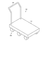
- FIG. 1 is a perspective view showing the external appearance of a truck equipped with a wheel module according to the first embodiment.
- FIG. 2 is a perspective view showing the outer appearance of the wheel module.
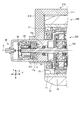
- FIG. 3 is a sectional view taken along line II of FIG.
- FIG. 4 is an enlarged view of the vicinity of the brake device shown in FIG.
- FIG. 5 is an enlarged view of a main part of an enlarged view near the elastic member shown in FIG.
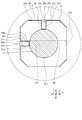
- FIG. 6 is a sectional view taken along line II-II of FIG.
- FIG. 7 is a perspective view showing the elastic member.
- FIG. 8 is a block diagram showing a functional configuration of a wheel module control system.
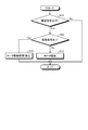
- FIG. 9 is a flowchart showing a processing procedure executed by the control device.
- FIG. 1 is a perspective view showing an external appearance of a trolley provided with a brake device according to an embodiment.
- the carriage 100 includes a luggage carrier 110, a handle 120, and a wheel module 200 having a brake device 20.
- the loading platform 110 constitutes a machine body.
- the luggage carrier 110 is a member formed in the shape of a thick plate, on the surface of which luggage is placed.
- the handle 120 is a curved rod-shaped member that the user holds when moving the carriage 100, and is attached to the upper surface of the luggage carrier 110.
- the wheel module 200 is a wheel that is rotated by a drive current supplied from a power source such as a battery (not shown), and is mounted on the back surface of the luggage carrier 110.
- the wheel module 200 is used as a moving mechanism of the carriage 100.
- the wheel module 200 is driven to assist the user when carrying a load on the luggage carrier 110, or when the carriage 100 has a function of self-propelling following another carriage 100. It is driven according to the distance from the carriage 100.
- the wheel module 200 may be provided as a front wheel, a middle wheel, or a rear wheel in the carriage 100, or may be provided as a front wheel, a middle wheel, or a rear wheel. It may be provided as a combination of the above. For example, in the case of a bogie with 6 wheels, the turning performance is improved, but the number of wheels provided such as 4 wheels is not limited.
- the wheel module 200 can also be used as a moving mechanism of a so-called service robot such as a transportation/transportation robot or a cleaning robot.
- FIG. 2 is a perspective view showing the outer appearance of the wheel module 200.
- the wheel module 200 has a connecting member 210 and a wheel portion 220.
- the wheel module 200 may be composed of only the wheel unit 220. 2 (including FIGS. 3 to 7), the X direction is the axial direction of the wheel module 200 in the present embodiment, the Y direction is orthogonal to the axial direction, and is the front-back direction of the wheel module 200 in the present embodiment. , Z direction is orthogonal to the axial direction and the front-rear direction, is the vertical direction of the wheel module 200 in the present embodiment, and is the vertical direction.
- the connecting member 210 is a member that connects the carriage 100 and the wheel portion 220.
- the connecting member 210 includes a fixing portion 211, a first holding portion 212, and a second holding portion 213.
- the fixed portion 211 and the first holding portion 212 may be formed separately or integrally.
- the fixing portion 211 is formed in a thick plate shape, and the upper surface 211a is attached and fixed to the back surface of the luggage carrier 110 (see FIG. 1) of the carriage 100.
- the first holding portion 212 is a member that extends downward from the end portion of the fixed portion 211.
- the second holding portion 213 is disposed below the first holding portion 212, and the first holding portion 212 is sandwiched between the first holding portion 212 and the lower end of the first holding portion 212 by a screw or the like. It is attached to 212. Accordingly, the wheel portion 220 is held by the first holding portion 212 and the second holding portion 213, and is connected to the carriage 100 via the fixing portion 211.
- the wheel unit 220 includes a tire 10, a wheel 11 (see FIG. 3, which will be described later), a drive unit 12, a braking operation of a wheel module 200 for decelerating and stopping the moving carriage 100, and a stopped carriage.
- the brake device 20 performs at least one of the stop and hold operation of the wheel module 200 for restricting the movement of the wheel 100, and the restriction release unit 40.
- the tire 10 is formed of an elastic member such as rubber.
- the tire 10 is a cylindrical member having a diameter of 100 to 300 mm, but is not limited to this.
- the wheel 11 is formed in a cylindrical shape, and the tire 10 is attached to the outer peripheral side thereof.
- the drive unit 12 is arranged inside the wheel 11, specifically, inside the wheel 11 in the radial direction, and rotates the wheel 11 about the rotation axis A.
- the drive unit 12 includes a stator 15, a rotor 16, a rotating shaft 17, and a housing 18.
- the stator 15 and the rotor 16 constitute an inner rotor type motor, and the rotor 16 rotates about the rotation axis A when a drive current is supplied.
- the rotational force generated by the rotation of the rotor 16 is transmitted to the wheel 11 via the rotary shaft 17 and a gear mechanism (for example, a planetary gear mechanism, not shown).
- a gear mechanism for example, a planetary gear mechanism, not shown.
- the stator 15 rotates the rotor 16 about the rotation axis A by the drive current.
- the stator 15 has a configuration in which a plurality of salient poles are arranged side by side in the circumferential direction on the inner peripheral surface of a stator base formed in a hollow cylindrical shape, and a coil is wound around each salient pole. To be turned.
- the rotor 16 is arranged radially inward of the stator 15, and rotates the wheel 11 with respect to the stator 15 about the rotation axis A to rotate the wheel 11.
- the rotor 16 has a configuration in which a plurality of magnets are arranged side by side in the circumferential direction along the outer peripheral surface of a base portion formed in a cylindrical shape, and each magnet corresponds to each coil of the stator 15. It is arranged so as to face each other. As a result, the rotor 16 rotates about the rotation axis A by the electromagnetic force generated in the coil of the stator 15 when the drive current flows through the coil.
- the rotating shaft 17 is arranged so that its axis coincides with the rotating axis A, and is fixed to the rotor 16 while penetrating the center of the rotor 16.
- the rotating shaft 17 is rotatably supported by the housing 18 via bearings 19a and 19b.
- the rotary shaft 17 rotates about the rotation axis A according to the rotation of the rotor 16.
- the rotary shaft 17 has a step portion 17a formed on the side opposite to the drive portion 12 side, and an outer diameter on the opposite side to the drive portion 12 side is formed smaller than an outer diameter on the drive portion 12 side of the step portion 17a.
- the rotary shaft 17 has a hole 17b formed on the side opposite to the drive unit 12 side with respect to the step 17a (see FIG. 6).
- the casing 18 is arranged inside the wheel 11 and accommodates the stator 15, the rotor 16, the rotating shaft 17, the gear mechanism (not shown), and the like.
- the brake device 20 is a device that restricts rotation of the rotary shaft 17, and is housed in a cylindrical case portion 30 (see FIG. 2 ).
- a non-excitation actuated brake negative actuation electromagnetic brake
- the brake device 20 and the like will be described in detail with reference to FIG.
- FIG. 4 is an enlarged view of the vicinity of the brake device 20 shown in FIG.
- the brake device 20 includes a boss 21, a brake disc 22, an elastic member 23, a friction plate 24, a fixing portion 25, an armature 26, a spring member 27, an electromagnetic coil 28, and A spring pin 29 is provided.
- FIG. 5 is an enlarged view of a main part of an enlarged view around the elastic member shown in FIG.
- FIG. 6 is a sectional view taken along line II-II of FIG.
- the boss 21 transmits the rotational force of the rotary shaft 17 to the brake disc 22.
- the boss 21 is specifically formed in a rectangular shape when viewed from the axial direction.
- the boss 21 has a through hole 21a, a through hole 21b, a groove portion 21c, and a receiving portion 21d.
- the boss 21 is an example of a torque transmission mechanism.
- the torque transmission mechanism is not limited to the boss 21, and may be a spline hub or the like.
- the through hole 21a is formed along the axial direction, and both ends in the axial direction communicate with the outside.
- a portion of the rotating shaft 17 on the side opposite to the drive portion 12 side with respect to the step portion 17a is inserted, and the movement of the boss 21 to the drive portion 12 side is restricted in the step portion 17a.
- the through hole 21b is for fixing the boss 21 to the rotary shaft 17.
- the through hole 21b is formed along the radial direction, and its end portion communicates with the outside on the outer peripheral surface of the boss 21.
- the through hole 21b faces the hole portion 17b when the boss 21 is inserted into the rotary shaft 17.
- the spring pin 29 is inserted into the through hole 21b and the hole portion 17b, so that the boss 21 is fixed to the rotating shaft 17 by restricting the movement of the boss 21 with respect to the rotating shaft 17 in the axial direction and the circumferential direction.
- the groove 21c accommodates the elastic member 23, and is formed by recessing inward from the outer peripheral surface of the boss 21.
- the groove portion 21c is formed on the outer peripheral surface of the boss 21 in two directions that intersect with each other at the center of the rotary shaft 17 when viewed in the axial direction, specifically, in two directions that are orthogonal to each other.
- the groove portions 21c are respectively formed on two adjacent sides of the four sides of the outer peripheral surface of the boss 21 which are orthogonal to each other when viewed from the axial direction.
- the receiving portion 21d is for fixing the elastic member 23, and is formed as the bottom surface of the groove portion 21c.
- the receiving portion 21d is formed so as to project radially outward from the rotary shaft 17 in the groove portion 21c.
- the receiving portion 21d is formed as an inclined surface that is inclined toward the inside of the receiving portion 21d as both end surfaces in the axial direction are directed radially inward.
- a protruding portion 23d which will be described later, protrudes outward in the radial direction from the outer peripheral surface of the boss 21 in a state where the elastic member 23 is fixed to the receiving portion 21d and no external force acts on the elastic member 23.
- the radially outer top surface is formed in consideration of the thickness of the elastic member 23.
- the brake disc 22 is a member formed in a disc shape, for example.
- the brake disc 22 has an insertion hole 22a into which the boss 21 is inserted.
- the insertion hole 22a is formed in a shape that restricts relative rotation of the brake disc 22 with respect to the boss 21 to be inserted. That is, the brake disc 22 rotates integrally with the rotary shaft 17 of the drive unit 12 that rotates the wheel 11.
- the brake disc 22 has an insertion hole 22a formed by an inner peripheral surface having a shape similar to the outer peripheral surface when viewed from the axial direction. Therefore, a gap H is formed between the boss 21 and the brake disc 22 so that the brake disc 22 can move in the axial direction with respect to the boss 21. That is, the brake disc 22 is supported by the boss 21 so as to be movable in the axial direction, and thus is supported so as to be movable in the axial direction with respect to the rotary shaft 17.
- the brake disc 22 is an example of a brake body.
- FIG. 7 is a perspective view showing the elastic member.
- the elastic member 23 rotates integrally with the rotary shaft 17 and urges the brake disc 22 in the radial direction.
- the elastic members 23 are made of an elastic material, for example, a metal material, correspond to the receiving portions 21d, and are fixed to the receiving portions 21d. That is, the elastic member 23 is fixed to the outer peripheral surface of the boss 21 at a position corresponding to two directions intersecting at the center of the rotary shaft 17, specifically, two directions orthogonal to each other when viewed from the axial direction. Has been done.
- the elastic member 23 has a main body 23a, a pair of grips 23b and 23c, and a protrusion 23d.
- the main body portion 23a faces the inner peripheral surface of the brake disc 22 in the radial direction when the elastic member 23 is fixed to the boss 21.
- the body portion 23a is formed in a flat plate shape having the axial direction as the extending direction.
- the pair of gripping portions 23b and 23c grip the receiving portion 21d in an elastically deformed state.
- the pair of gripping portions 23b and 23c respectively project from both ends in the axial direction of the main body portion 23a in the extending direction of the main body portion 23a, that is, in the radial direction which is a direction orthogonal to the axial direction.
- the pair of grip portions 23b and 23c are formed so that the length in the axial direction is shorter than that of the main body portion 23a.
- the pair of gripping portions 23b and 23c are formed so as to be inclined so as to come close to each other as they protrude in the radial direction such that the shortest length L2 in the axial direction is shorter than the length L1 of the main body portion 23a. Has been done.
- the pair of gripping portions 23b and 23c in the axial direction is set so that the axial length of the pair of gripping portions 23b and 23c is longer than that of the main body portion 23a.
- it is pushed outward, it is elastically deformed and brought into contact with both axial end surfaces of the receiving portion 21d in an elastically deformed state.
- the protrusion 23d comes into contact with the brake disc 22 in an elastically deformed state.
- the protruding portion 23d is formed so as to protrude toward the brake disc 22 side in the radial direction from the outer peripheral surface of the boss 21 in a state where the elastic member 23 is fixed to the boss 21 and no external force acts on the elastic member 23. ing.
- the friction plate 24 makes sliding contact with the brake disc 22 to regulate the rotation of the rotary shaft 17.
- the friction plate 24 includes a first friction plate 24a and a second friction plate 24b.
- the first and second friction plates 24a and 24b are formed, for example, in an annular shape, and are arranged so that the rotary shaft 17 penetrates through a central hole.
- first friction plate 24a and the second friction plate 24b are arranged along the direction of the rotation axis A with the brake disc 22 interposed therebetween.
- the first and second friction plates 24a and 24b configured as described above are specifically attached to both surfaces of the brake disc 22 in the axial direction, and are arranged in the axial direction of the brake disc 22 with respect to the rotary shaft 17. It moves with the movement.
- the friction plate 24 including the first and second friction plates 24a and 24b is an example of a friction body.
- the fixing portion 25 is formed, for example, in an annular shape, and is arranged so that the rotary shaft 17 penetrates through the central hole.
- the fixed portion 25 is arranged so as to be adjacent to the second friction plate 24b along the direction of the rotation axis A.
- the fixing portion 25 is arranged to face the surface of the second friction plate 24b opposite to the surface on which the brake disc 22 and the spring member 27 are arranged, and is fixed to the case portion 30. .. That is, the fixed portion 25 does not rotate integrally even if the rotating shaft 17 rotates.
- the fixing portion 25 is arranged in the axial direction together with the armature 26 with the first and second friction plates 24a and 24b interposed therebetween.
- the fixed portion 25 is an example of a non-rotating body.
- the armature 26 has magnetism and is formed in a ring shape, for example. Further, the rotary shaft 17 is arranged to penetrate through the central hole of the armature 26.
- the armature 26 is arranged so as to be adjacent to the first friction plate 24a along the direction of the rotation axis A. Specifically, the armature 26 is arranged so as to face the surface of the first friction plate 24 a on which the brake disc 22 and the spring member 27 are arranged, and is fixed to the case portion 30 via the electromagnetic coil 28.
- the armature 26 is arranged in the axial direction with the fixed portion 25, sandwiching the first and second friction plates 24a and 24b.
- the armature 26 is an example of a non-rotating body.
- the spring member 27 is arranged so that one end contacts the armature 26.
- a coil spring can be used as the spring member 27.
- the spring member 27 is arranged so that the other end thereof contacts the pin 41.
- the spring member 27 and the pin 41 are arranged in a hole 28c formed in the electromagnetic coil 28 adjacent to the armature 26.
- FIG. 4 shows a state before the restriction releasing portion 40 operates, and in this state, the spring member 27 is compressed and interposed between the pin 41 and the armature 26. As a result, the spring member 27 urges the armature 26 and the brake disc 22 toward the fixed portion 25, as shown by the arrow F1. As described above, due to the bias, the first and second friction plates 24a and 24b are brought into sliding contact with the armature 26 and the fixed portion 25 to generate friction, and the rotation of the rotary shaft 17 is restricted.
- the member that biases the armature 26 and the brake disc 22 toward the fixed portion 25 side is the spring member 27, but the member is not limited to this, and other members may be used as long as they can be biased.
- the electromagnetic coil 28 includes a yoke 28a and a coil 28b.
- the yoke 28a is formed in a cylindrical shape, and the rotating shaft 17 is arranged so as to pass through the central hole.
- the coil 28b is wound around the outer circumference of the yoke 28a.
- the yoke 28a is formed with a hole 28c in which the spring member 27 and the pin 41 described above are arranged.
- the electromagnetic coil 28, together with the spring member 27, is an example of a moving mechanism that changes the relative distance between the fixed portion 25 and the armature 26 in the axial direction.
- the electromagnetic coil 28 is energized when the rotation of the rotary shaft 17 is restricted by the spring member 27 to the non-rotation restricted state in which the restriction of the rotation of the rotary shaft 17 is released. Done in.
- a driving current is supplied to the coil 28b from a power source such as a battery (not shown)
- a driving current is supplied to the coil 28b from a power source such as a battery (not shown)
- an electromagnetic force is generated and the armature 26 is attracted to the electromagnetic coil 28 side against the biasing force of the spring member 27.
- the relative distance between the fixed portion 25 and the armature 26 in the axial direction becomes long, the brake disc 22 is separated from the fixed portion 25 and the armature 26, that is, the first friction plate 24a is separated from the armature 26, and the second friction The plate 24b is separated from the fixed portion 25, so that the regulation of the rotation of the rotary shaft 17 is released, and the non-rotation regulation state is established.
- the electromagnetic coil 28 separates the brake disc 22 from the fixed portion 25 and the armature 26 against the biasing force of the spring member 27 by energization, and releases the regulation of the rotation of the rotary shaft 17.
- the regulation releasing unit 40 that can release the regulation of the rotation of the rotating shaft 17 by a manual operation is provided. Further, in the wheel module 200 according to the present embodiment, it is possible to detect that the restriction on the rotation of the rotating shaft 17 has been released by a manual operation using the restriction release unit 40.
- the restriction releasing unit 40 includes the pin 41 described above.
- the restriction releasing portion 40 normally releases the movement of the pin 41 in the axial direction by operating the operating portion from the pin regulation state in which the movement of the pin 41 in the axial direction is regulated, and the spring member 27 causes the arrow to move. This is to shift to the non-pin restricted state in which the biasing force is not generated in the direction indicated by F1.
- the wheel module 200 includes a release detection sensor 61 and a rotation angle sensor 71.
- the release detection sensor 61 detects that the regulation release section 40 has released the regulation of the rotation of the rotating shaft 17. Thereby, for example, as will be described later, it becomes possible to appropriately control the drive unit 12 and the like when the regulation of the rotation of the rotary shaft 17 is released by a manual operation, thereby improving the safety. ..
- the release detection sensor 61 described above is, for example, a proximity sensor that includes a Hall IC or the like, and detects a change in magnetic flux due to movement (thrust movement) of the detection magnet 62 to detect the distance to the detection magnet 62. is there.
- the detection magnet 62 is attached to a member that moves in the axial direction, for example, the operation unit when the restriction release unit 40 enters the non-rotationally restricted state, and the release detection sensor 61 is arranged at a position facing the detection magnet 62. I was made to do it.
- the release detection sensor 61 is mounted on the board 60 provided in the case portion 30.
- the release detection sensor 61 is brought into the non-rotationally restricted state by the restriction release section 40, and when the detection magnet 62 moves in the direction of separation, the restriction release section 40 releases the restriction of rotation of the rotary shaft 17. Can be detected. Specifically, the release detection sensor 61 outputs a release signal indicating release of the restriction on the rotation of the rotating shaft 17 by the restriction release unit 40 when the restriction release unit 40 enters the non-rotation restricted state.
- the release detection sensor 61 is arranged coaxially with the rotation axis A of the rotation shaft 17. As a result, the space on the rotation axis A of the rotation shaft 17 can be effectively used, and the wheel module 200 can be downsized in the radial direction.
- the rotation angle sensor 71 detects the rotation angle of the rotating shaft 17.
- the rotation angle sensor 71 is an encoder that includes a Hall IC or the like and detects the rotation angle of the detection magnet 72 by detecting a change in magnetic flux accompanying the rotation of the detection magnet 72.
- the detection magnet 72 is mounted on the rotation axis A of the rotation shaft 17 in a member that does not rotate even if the rotation shaft 17 rotates, and in a position facing the detection magnet 72, in other words, the rotation shaft 17
- the rotation angle sensor 71 is arranged coaxially with the.
- the rotation angle sensor 71 can detect the rotation angle of the rotary shaft 17, and outputs a rotation angle signal indicating the detected rotation angle of the rotary shaft 17.
- the rotation angle sensor 71 is disposed coaxially with the rotation axis A of the rotation shaft 17, the space on the rotation axis A of the rotation shaft 17 can be effectively used and the diameter of the wheel module 200 can be increased. It is possible to reduce the size in the direction.
- the rotation angle sensor 71 is mounted on the substrate 60. That is, the release detection sensor 61 and the rotation angle sensor 71 are provided on the same substrate 60. Specifically, the substrate 60 is arranged on the side opposite to the drive unit 12 side with respect to the rotary shaft 17, and the release detection sensor 61 is provided on one main surface 60a of the two main surfaces 60a and 60b. The rotation angle sensor 71 is provided on the other main surface 60c opposite to the main surface 60a.
- the release detection sensor 61 and the rotation angle sensor 71 can share the substrate 60, and the wheel module 200 can be downsized by the amount of the substrate that is unnecessary due to the sharing.
- the release detection sensor 61 and the rotation angle sensor 71 are both arranged coaxially with the rotation axis A of the rotation shaft 17, the space on the rotation axis A of the rotation shaft 17 can be used more effectively. At the same time, it is possible to further reduce the size of the wheel module 200 in the radial direction.
- the wheel module 200 may include various sensors 81 (see FIG. 7) other than the release detection sensor 61 and the rotation angle sensor 71.
- the various sensors 81 are, for example, sensors used for drive control of the wheel module 200.
- a sensor that detects a start request from a user a sensor that detects a distance from another trolley 100 when the trolley 100 has a function of self-propelling following another trolley 100, and the like. But is not limited to these.
- the various sensors 81 output signals indicating the detected information.
- FIG. 8 is a block diagram showing a functional configuration of the control system S of the wheel module 200 according to this embodiment.
- the control system S includes a control device 80, a drive unit 12, and a braking device 20.
- the control device 80 includes a release detection sensor 61, a rotation angle sensor 71, various sensors 81, and a control unit 90.
- the release detection sensor 61 outputs a release signal to the control unit 90 when the restriction release unit 40 enters the non-rotation restricted state.
- the rotation angle sensor 71 outputs a rotation angle signal to the control unit 90 when the rotation angle of the rotating shaft 17 is detected.
- the various sensors 81 output a signal indicating the detected information to the control unit 90.
- the control unit 90 is, for example, a microcomputer having a CPU and the like.
- the control unit 90 controls the drive unit 12 and the brake device 20 based on various signals output from the release detection sensor 61 and the like.
- control unit 90 controls the speed and position of the carriage 100 by performing a control of outputting a drive command to the drive unit 12 and the brake device 20 based on the rotation angle signal from the rotation angle sensor 71.
- the regulation release section 40 is manually operated because the braking apparatus 20 is fixed in a state in which the rotation of the rotating shaft 17 is regulated when a failure such that the braking apparatus 20 cannot be energized or a battery runs out, for example.
- the restriction on the rotation of the rotary shaft 17 is released. Therefore, for example, if the drive unit 12 is driven again in a state where the rotation restriction is manually released, the rotation of the rotary shaft 17 may not be restricted and may not be stopped because the electromagnetic brake is not applied.
- control unit 90 determines whether or not the release signal is output from the release detection sensor 61, and controls the drive unit 12 based on the determination result. For example, the control unit 90 can limit the drive of the drive unit 12 when it is determined that the release signal is output from the release detection sensor 61.
- the drive of the drive unit 12 is not limited to, for example, a limit of lowering the upper limit speed of the carriage 100 and narrowing of the maximum turning angle, but the drive of the drive unit 12 is prohibited. May be included.
- control unit 90 may notify the user that the rotation restriction has been released by a manual operation when it is determined that the release signal is output from the release detection sensor 61.
- FIG. 9 is a flowchart showing a processing procedure executed by the control device 80.
- control unit 90 of the control device 80 determines whether or not a drive command to the drive unit 12 or the like is output based on the rotation angle signal of the rotation angle sensor 71 and the like (step S10). .. When it is not determined that the drive command is output (step S10, No), the control unit 90 skips the subsequent processing.
- step S10 When it is determined that the drive command is output (step S10, Yes), the control unit 90 determines whether or not there is a release signal from the release detection sensor 61 (step S11). When it is determined that there is no cancellation signal (No at Step S11), the control unit 90 controls the drive unit 12 according to the drive command, in other words, performs normal control (motor drive) (Step S12). On the other hand, when it is determined that the release signal is present (Yes in step S11), the control unit 90 limits the drive of the drive unit 12 (motor drive limit) (step S13).
- the brake device 20 includes the boss 21, the brake disc 22, the elastic member 23, the pair of friction bodies 24a and 24b, the fixing portion 25, the armature 26, and the spring member 27. And an electromagnetic coil 28.
- the brake disc 22 rotates integrally with the rotary shaft 17 of the drive unit 12 that rotates the wheel 11, and is supported movably in the axial direction of the rotary shaft 17.
- the pair of friction bodies 24a and 24b are arranged in the axial direction with the brake disc 22 interposed therebetween.
- the fixed portion 25 and the armature 26 are arranged in the axial direction with the pair of friction bodies 24a and 24b interposed therebetween.
- the spring member 27 and the electromagnetic coil 28 change the relative distance between the fixed portion 25 and the armature 26 in the axial direction.
- the boss 21 transmits the rotational force of the rotary shaft 17 to the brake disc 22.
- the elastic member 23 rotates integrally with the rotary shaft 17 and biases the brake disc 22 in the radial direction.
- each elastic member 23 in a state where each elastic member 23 is housed in each groove 21c and the receiving portion 21d is gripped by the pair of gripping portions 23b and 23c, the projecting portion 23d projects radially outward from the outer peripheral surface of the boss 21.
- Each elastic member 23 is in an elastically deformed state by the protrusion 23d contacting the inner peripheral surface of the brake disc 22.
- the brake disc 22 is pushed to the opposite side of the side where each elastic member 23 is arranged with the center interposed therebetween by the biasing force generated by the elastic deformation of each elastic member 23.
- the outer peripheral surface of the boss 21 contacts the inner peripheral surface of the brake disc 22.
- the gap H on the side opposite to the side where each elastic member 23 is arranged with the center interposed therebetween disappears, and the gap H exists on the side where each elastic member 23 is arranged. It comes into contact with the disk 22 in an elastically deformed state.
- the brake disc 22 moves in the radial direction with respect to the rotary shaft 17 in a non-rotationally restricted state of the rotary shaft 17, that is, in the state where the brake disc 22 is allowed to move in the axial direction with respect to the rotary shaft 17.
- the elastic member 23 is fixed to the boss 21 at a position corresponding to two directions orthogonal to each other at the center of the rotary shaft 17, but the present invention is not limited to this, and for example, intersects. It may be fixed at a position corresponding to two directions, or may be fixed at a position corresponding to four orthogonal directions, for example, the width direction and the vertical direction.
- the boss 21 is included as a component in the rotational force transmission mechanism, but the present invention is not limited to this, and the rotary shaft 17 may function as the rotational force transmission mechanism.
- the rotary shaft 17 may function as the rotational force transmission mechanism.
- the elastic member 23 is fixed to the rotary shaft 17 by forming a groove portion that is recessed inward and a receiving portion, and holding the receiving portion by the pair of holding portions 23b and 23c.
- the friction plate 24 is configured to sandwich the brake disc 22 between the first friction plate 24a and the second friction plate 24b, but the present invention is not limited to this, and for example, a plurality of types Other friction plates such as a multi-plate type in which the friction bodies formed in the above shape are laminated may be used.
- the present invention is not limited to the above-described embodiments.
- the present invention also includes those configured by appropriately combining the above-described constituent elements. Further, further effects and modified examples can be easily derived by those skilled in the art. Therefore, the broader aspect of the present invention is not limited to the above-described embodiment, and various modifications can be made.
Landscapes
- Engineering & Computer Science (AREA)
- General Engineering & Computer Science (AREA)
- Mechanical Engineering (AREA)
- Braking Arrangements (AREA)
Abstract
実施形態に係るブレーキ装置は、ボス(21)と、ブレーキディスク(22)と、弾性部材(23)と、を少なくとも備える。ボス(21)は、回転シャフト(17)の回転力をブレーキディスク(22)に伝達する。ブレーキディスク(22)は、ホイールを回転させる駆動部の回転シャフト(17)と一体回転し、かつ回転シャフト(17)の軸方向に移動自在に支持される。弾性部材(23)は、回転シャフト(17)と一体回転し、かつブレーキディスク(22)を径方向に付勢する。
Description
本発明は、ブレーキ装置、車輪モジュール、および、移動機構に関する。
従来、駆動モータの回転シャフトの回転を規制するブレーキ装置が種々提案されている。ブレーキ装置としては、例えば、バネを用いてアーマチュアを回転シャフトとともに回転する回転円板へ付勢することで回転シャフトの回転を規制する一方、電磁コイルに通電してアーマチュアを回転体から離間させることで制動を解除するブレーキ装置が知られている(例えば特許文献1参照)。
ところで、回転円板は、回転シャフトの回転を規制するために、回転シャフトに対して軸方向に移動することを許容されるものである。従って、回転円板は、回転シャフトに固定されるスプラインハブ(ボス)に対して、径方向において隙間が形成されている。一方、回転円板は、回転シャフトの回転を規制していない状態においては、スプラインハブに対して軸方向に移動自在であるとともに、径方向おいても移動自在となる。つまり、回転円板は、径方向において隙間分移動することが許容されることとなり、振動・騒音が発生する恐れがある。
本発明は、上記に鑑みてなされたものであって、回転シャフトの非回転規制状態における振動・騒音の発生を抑制することができるブレーキ装置、車輪モジュール、および、移動機構を提供することを目的とする。
上述した課題を解決し、目的を達成するために、本発明の一態様に係るブレーキ装置は、ブレーキ体と、摩擦体と、一対の非回転体と、移動機構と、回転力伝達機構と、弾性部材とを少なくとも備える。ブレーキ体は、ホイールを回転させる駆動部の回転シャフトと一体回転し、かつ前記回転シャフトの軸方向に移動自在に支持される。摩擦体は、前記ブレーキ体を挟んで、軸方向において配置される。一対の非回転体は、前記摩擦体を挟んで、軸方向において配置される。移動機構は、前記一対の非回転体の軸方向における相対距離を変更する。回転力伝達機構は、前記回転シャフトの回転力を前記ブレーキ体に伝達する。弾性部材は、前記回転シャフトと一体回転し、かつ前記ブレーキ体を径方向に付勢する。
本発明の一態様によれば、回転シャフトの非回転規制状態における振動・騒音の発生を抑制することができる。
[実施形態]
以下、実施形態に係るブレーキ装置、車輪モジュールおよび移動機構について図面を参照して説明する。なお、図面は模式的なものであり、図面における各要素の寸法の関係、各要素の比率などは、現実と異なる場合がある。また、図面の相互間においても、互いの寸法の関係や比率が異なる部分が含まれている場合がある。
以下、実施形態に係るブレーキ装置、車輪モジュールおよび移動機構について図面を参照して説明する。なお、図面は模式的なものであり、図面における各要素の寸法の関係、各要素の比率などは、現実と異なる場合がある。また、図面の相互間においても、互いの寸法の関係や比率が異なる部分が含まれている場合がある。
<車輪モジュールを備えた台車の構成>
図1は、実施形態に係るブレーキ装置を備えた台車の外観を示す斜視図である。図1に示すように、台車100は、荷台110と、取っ手120と、ブレーキ装置20を有する車輪モジュール200とを備える。荷台110は、機体を構成する。
図1は、実施形態に係るブレーキ装置を備えた台車の外観を示す斜視図である。図1に示すように、台車100は、荷台110と、取っ手120と、ブレーキ装置20を有する車輪モジュール200とを備える。荷台110は、機体を構成する。
荷台110は、厚板状に形成された部材であり、表面に荷物が載せられる。取っ手120は、利用者が台車100を移動する際に把持するための湾曲した棒状の部材であり、荷台110の上面に取り付けられている。車輪モジュール200は、図示していないバッテリなどの電源から供給される駆動電流によって回転する車輪であり、荷台110の裏面に取り付けられている。
車輪モジュール200は、台車100の移動機構として用いられる。例えば、車輪モジュール200は、利用者が荷台110に荷物を載せて運搬する際の補助用に駆動されたり、台車100が他の台車100に追従して自走する機能を有する場合に、他の台車100との間の距離に応じて駆動されたりする。なお、車輪モジュール200は、台車100に前輪として備えられてもよいし、中輪として備えられてもよいし、後輪として備えられてもよいし、前輪・中輪・後輪のいずれか2以上の組み合わせとして備えられてもよい。例えば、6輪の台車とした場合、旋回性能が高くなるが、4輪等、備えられる車輪の数は限定されない。
また、車輪モジュール200は、例えば、運送・搬送用ロボットや、清掃用ロボット等の所謂サービスロボットの移動機構として用いることもできる。
図2は、車輪モジュール200の外観を示す斜視図である。図2に示すように、車輪モジュール200は、接続部材210と、車輪部220とを有する。なお、車輪モジュール200は、車輪部220のみで構成されてもよい。図2(図3~図7も含む)は、X方向が本実施形態における車輪モジュール200の軸方向であり、Y方向が軸方向と直交し、本実施形態における車輪モジュール200の前後方向であり、Z方向は、軸方向および前後方向と直交し、本実施形態における車輪モジュール200の上下方向であり、鉛直方向である。
接続部材210は、台車100と車輪部220とを接続する部材である。例えば、接続部材210は、固定部211と、第1保持部212と、第2保持部213とを備える。なお、固定部211と第1保持部212とは、別体に形成されてもよいし、一体に形成されてもよい。
固定部211は、厚板状に形成されるとともに、上面211aが台車100における荷台110(図1参照)の裏面に取り付けられて固定される。第1保持部212は、固定部211の端部から下方に延在する部材である。第2保持部213は、第1保持部212の下方に配置され、第1保持部212の下端との間に車輪部220の一部を挟んだ状態で、例えばネジなどにより、第1保持部212に取り付けられる。これにより、車輪部220は、第1保持部212および第2保持部213によって保持されつつ、固定部211を介して台車100に接続される。
車輪部220は、タイヤ10と、ホイール11(後述する図3参照)と、駆動部12と、移動中の台車100の減速・停止を行うための車輪モジュール200の制動動作、および停止中の台車100の移動を規制するための車輪モジュール200の停止保持動作の少なくとも一方を行うブレーキ装置20と、規制解除部40とを備える。
図3は、図2のI-I線断面図であり、また、軸方向に沿った車輪モジュール200の断面図である。図3に示すように、タイヤ10は、ゴムなど弾力性を有する部材によって形成される。例えば、タイヤ10は、円筒状の部材であり、直径は100~300mmであるが、これに限られない。ホイール11は、円筒状に形成され、外周側にタイヤ10が取り付けられる。
<駆動部の構成>
駆動部12は、ホイール11の内側、具体的には、ホイール11よりも径方向内側に配置され、回転軸Aを中心にホイール11を回転させる。例えば、駆動部12は、ステータ15と、ロータ16と、回転シャフト17と、筐体18とを備える。
駆動部12は、ホイール11の内側、具体的には、ホイール11よりも径方向内側に配置され、回転軸Aを中心にホイール11を回転させる。例えば、駆動部12は、ステータ15と、ロータ16と、回転シャフト17と、筐体18とを備える。
例えば、ステータ15とロータ16とはインナーロータ型のモータを構成しており、駆動電流が供給されることによって、回転軸Aを中心にロータ16が回転する。ロータ16の回転によって発生した回転力は、回転シャフト17および歯車機構(例えば遊星歯車機構。図示せず)を介してホイール11に伝達される。これにより、ホイール11とともにタイヤ10が回転する。
ステータ15は、駆動電流によって、回転軸Aを中心にロータ16を回転させる。具体的には、ステータ15は、中空の円筒状に形成されたステータ基部の内周面に複数の突極が周方向に並べて配置された構成を有しており、各突極にコイルが巻回される。
ロータ16は、ステータ15よりも径方向内側に配置されており、ステータ15に対して回転軸Aを中心に回転することで、ホイール11を回転させる。具体的には、ロータ16は、円柱状に形成された基部の外周面に沿って複数の磁石が周方向に並べて配置された構成を有しており、各磁石が、ステータ15の各コイルと対向するように配置される。これにより、ロータ16は、ステータ15のコイルに駆動電流が流れた際にコイルに発生する電磁力によって、回転軸Aを中心に回転する。
回転シャフト17は、軸心が回転軸Aと一致するように配置され、ロータ16の中心を貫通した状態で、ロータ16に固定されている。ここで、回転シャフト17は、ベアリング19a,19bを介して回転自在に筐体18に支持される。これにより、回転シャフト17は、ロータ16の回転に応じて、回転軸Aを中心に回転する。回転シャフト17は、駆動部12側と反対側に段差部17aが形成され、段差部17aよりも駆動部12側の外径よりも、駆動部12側と反対側の外径が小さく形成されている。回転シャフト17は、段差部17aよりも駆動部12側と反対側に孔部17bが形成されている(図6参照)。
筐体18は、ホイール11の内側に配置され、上記したステータ15、ロータ16、回転シャフト17および図示しない歯車機構などを収容する。
<ブレーキ装置の構成>
次に、ブレーキ装置20について説明する。ブレーキ装置20は、回転シャフト17の回転を規制する装置であり、円筒状のケース部30に収容される(図2参照)。ブレーキ装置20としては、例えば無励磁作動ブレーキ(負作動電磁ブレーキ)を用いることができる。かかるブレーキ装置20などについて図4以降を参照して詳しく説明する。
次に、ブレーキ装置20について説明する。ブレーキ装置20は、回転シャフト17の回転を規制する装置であり、円筒状のケース部30に収容される(図2参照)。ブレーキ装置20としては、例えば無励磁作動ブレーキ(負作動電磁ブレーキ)を用いることができる。かかるブレーキ装置20などについて図4以降を参照して詳しく説明する。
図4は、図3に示すブレーキ装置20付近の拡大図である。図4に示すように、ブレーキ装置20は、ボス21と、ブレーキディスク22と、弾性部材23と、摩擦板24と、固定部25と、アーマチュア26と、ばね部材27と、電磁コイル28と、スプリングピン29を備える。
図5は、図4に示す弾性部材付近の拡大図の要部拡大図である。図6は、図4のII-II線断面図である。図5および図6に示すように、ボス21は、回転シャフト17の回転力をブレーキディスク22に伝達するものである。ボス21は、具体的に、軸方向から見た場合に、矩形状に形成されている。ボス21は、貫通穴21aと、貫通孔21bと、溝部21cと、受け部21dとを有する。なお、ボス21は、回転力伝達機構の一例である。なお、回転力伝達機構は、ボス21に限定されるものではなく、スプラインハブなどであってもよい。
貫通穴21aは、軸方向に沿って形成されており、軸方向における両端部が外部と連通する。貫通穴21aは、回転シャフト17のうち、段差部17aよりも駆動部12側と反対側の部分が挿入され、段差部17aにおいて、ボス21の駆動部12側への移動が規制される。
貫通孔21bは、ボス21を回転シャフト17に固定するものである。貫通孔21bは、径方向に沿って形成されており、端部がボス21の外周面において外部と連通する。貫通孔21bは、ボス21が回転シャフト17に挿入された状態において、孔部17bと対向する。ここで、ボス21は、スプリングピン29が貫通孔21bおよび孔部17bに挿通されることで、回転シャフト17に対するボス21の軸方向および周方向への移動が規制され、回転シャフト17に固定される。
溝部21cは、弾性部材23を収容するものであり、ボス21の外周面から内側に凹んで形成されている。溝部21cは、ボス21の外周面において、軸方向から見た場合に、回転シャフト17の中心において交差する2方向、具体的には直交する2方向に形成されている。ここでは、溝部21cは、軸方向から見た場合において、ボス21の外周面のうち直交する4辺のうち、隣り合う2辺にそれぞれ形成されている。
受け部21dは、弾性部材23が固定するものであり、溝部21cの底面として形成されている。受け部21dは、溝部21cにおいて回転シャフト17から径方向外側に突出して形成されている。ここで、受け部21dは、軸方向における両端面が径方向内側に向かうにともない、受け部21dの内部に向かって傾斜する傾斜面として形成されている。受け部21dは、受け部21dに弾性部材23が固定された状態、かつ弾性部材23に外力が作用していない状態において、後述する突出部23dがボス21の外周面よりも径方向外側に突出するように、径方向外側の頂面が弾性部材23の厚みを考慮して形成されている。
ブレーキディスク22は、例えば円板状に形成される部材である。ブレーキディスク22は、ボス21が挿入される挿入穴22aが形成されている。挿入穴22aは、挿入されるボス21に対するブレーキディスク22の相対回転を規制する形状に形成されている。つまり、ブレーキディスク22は、ホイール11を回転させる駆動部12の回転シャフト17と一体回転するものである。ブレーキディスク22は、具体的には、軸方向から見た場合における外周面と相似形状の内周面により挿入穴22aが形成されている。従って、ボス21とブレーキディスク22との間には、ボス21に対してブレーキディスク22が軸方向に移動自在となるように、隙間Hが形成されている。つまり、ブレーキディスク22は、ボス21に対して軸方向に移動自在に支持されることで、回転シャフト17に対して軸方向に移動自在に支持される。なお、ブレーキディスク22は、ブレーキ体の一例である。
図7は、弾性部材を示す斜視図である。図5~図7に示すように、弾性部材23は、回転シャフト17と一体回転し、かつブレーキディスク22を径方向に付勢するものである。弾性部材23は、弾性を有する材料、例えば金属材料により構成されており、受け部21dにそれぞれ対応するものであり、受け部21dにそれぞれ固定される。つまり、弾性部材23は、ボス21の外周面のうち、軸方向から見た場合に、回転シャフト17の中心において交差する2方向、具体的には直交する2方向に対応する位置に、それぞれ固定されている。弾性部材23は、本体部23aと、一対の把持部23b、23c、突出部23dとを有する。
本体部23aは、弾性部材23がボス21に固定された状態において、ブレーキディスク22の内周面と径方向において対向するものである。本体部23aは、軸方向を延在方向とする平板状に形成されている。
一対の把持部23b,23cは、受け部21dを弾性変形した状態で把持するものである。一対の把持部23b,23cは、本体部23aの軸方向における両端部から本体部23aの延在方向、すなわち軸方向と直交する方向である径方向にそれぞれ突出するものである。一対の把持部23b,23cは、軸方向における長さが本体部23aよりも短く形成されている。一対の把持部23b,23cは、軸方向における最も短い長さL2が、本体部23aの長さL1よりも短くなるように、径方向に突出するにともない、互いに近接するように傾斜して形成されている。つまり、弾性部材23を受け部21dに固定する場合は、一対の把持部23b,23cの軸方向における長さが本体部23aよりも長くなるように、一対の把持部23b、23cを軸方向における外側に押し広げることで、弾性変形させ、受け部21dの軸方向における両端面に弾性変形した状態で接触させる。
突出部23dは、ブレーキディスク22と弾性変形した状態で接触するものである。突出部23dは、弾性部材23がボス21に固定された状態、かつ弾性部材23に外力が作用していない状態において、ボス21の外周面よりも径方向においてブレーキディスク22側に突出して形成されている。
摩擦板24は、ブレーキディスク22と摺接して回転シャフト17の回転を規制する。具体的には、摩擦板24は、第1摩擦板24aと、第2摩擦板24bとを備える。第1、第2摩擦板24a,24bは、例えば環状に形成され、中央の孔には回転シャフト17が貫通するように配置される。
また、第1摩擦板24aと第2摩擦板24bとは、ブレーキディスク22を間に挟むようにして回転軸Aの方向に沿って配置される。上記のように構成された第1、第2摩擦板24a,24bは、具体的には、ブレーキディスク22の軸方向における両表面に取り付けられており、ブレーキディスク22の回転シャフト17に対する軸方向の移動にともない、移動する。なお、第1、第2摩擦板24a,24bを含む摩擦板24は、摩擦体の一例である。
固定部25は、例えば環状に形成され、中央の孔には回転シャフト17が貫通するように配置される。また、固定部25は、第2摩擦板24bに対して回転軸Aの方向に沿って隣接するように配置される。詳しくは、固定部25は、第2摩擦板24bにおいてブレーキディスク22やばね部材27が配置される側の面とは反対側の面と対向するように配置されて、ケース部30に固定される。つまり、固定部25は、回転シャフト17が回転しても、一体回転するものではない。固定部25は、アーマチュア26ともに、第1、第2摩擦板24a,24bを挟んで、軸方向において配置されるものである。なお、固定部25は、非回転体の一例である。
アーマチュア26は、磁性を有し、例えば環状に形成される。また、アーマチュア26の中央の孔には、回転シャフト17が貫通するように配置される。アーマチュア26は、第1摩擦板24aに対して回転軸Aの方向に沿って隣接するように配置される。詳しくは、アーマチュア26は、第1摩擦板24aにおいてブレーキディスク22やばね部材27が配置される側の面と対向するように配置されて、電磁コイル28を介してケース部30に固定される。アーマチュア26は、固定部25ともに、第1、第2摩擦板24a,24bを挟んで、軸方向において配置されるものである。なお、アーマチュア26は、非回転体の一例である。
ばね部材27は、一端がアーマチュア26と当接するように配置される。ばね部材27としては、例えばコイルばねを用いることができる。また、ばね部材27は、他端がピン41と当接するように配置される。ばね部材27およびピン41は、アーマチュア26と隣接する電磁コイル28に形成された孔28c内に配置される。
上記したピン41は、規制解除部40の構成要素である。図4は、規制解除部40が作動する前の状態を示しており、かかる状態では、ばね部材27は、ピン41とアーマチュア26との間に圧縮されて介装される。これにより、ばね部材27は、矢印F1で示すように、アーマチュア26、ブレーキディスク22を固定部25側へ付勢することとなる。上記したように、かかる付勢により、第1、第2摩擦板24a,24bは、アーマチュア26および固定部25に対してそれぞれ摺接して摩擦が生じ、回転シャフト17の回転が規制される。
なお、上記では、アーマチュア26およびブレーキディスク22を固定部25側へ付勢する部材をばね部材27としたが、これに限定されるものではなく、付勢できればその他の部材であってもよい。
電磁コイル28は、ヨーク28aと、コイル28bとを備える。ヨーク28aは、円筒状に形成され、中央の孔には、回転シャフト17が貫通するように配置される。コイル28bは、ヨーク28aの外周側に巻回される。なお、ヨーク28aには、上記したばね部材27やピン41が配置される孔28cが形成される。なお、電磁コイル28は、ばね部材27とともに、固定部25およびアーマチュア26の軸方向における相対距離を変更する移動機構の一例である。
ブレーキ装置20は、ばね部材27により、回転シャフト17の回転が規制される回転規制状態から回転シャフト17の回転の規制の解除される非回転規制状態への移行は、電磁コイル28へ通電することで行われる。例えば、図示しないバッテリなどの電源からコイル28bに駆動電流が供給されると、電磁力が発生し、アーマチュア26は、ばね部材27の付勢力に抗して電磁コイル28側へ吸着される。これにより、固定部25およびアーマチュア26との軸方向における相対距離が長くなり、ブレーキディスク22が固定部25およびアーマチュア26から離間、すなわち第1摩擦板24aがアーマチュア26から離間するとともに、第2摩擦板24bが固定部25から離間し、よって回転シャフト17の回転の規制が解除され、非回転規制状態となる。
このように、電磁コイル28は、通電によってばね部材27の付勢力に抗してブレーキディスク22を固定部25およびアーマチュア26から離間から離間させて、回転シャフト17の回転の規制を解除する。
<規制解除部の構成>
ところで、例えば上記した電磁コイル28へ通電できないような故障やバッテリ切れ等が発生した場合、電磁コイル28では、回転シャフト17の回転の規制を解除することができない。
ところで、例えば上記した電磁コイル28へ通電できないような故障やバッテリ切れ等が発生した場合、電磁コイル28では、回転シャフト17の回転の規制を解除することができない。
そこで、本実施形態に係る車輪モジュール200にあっては、例えば、手動操作によって回転シャフト17の回転の規制を解除できる規制解除部40を備えるようにした。また、本実施形態に係る車輪モジュール200においては、規制解除部40を用いた手動操作によって回転シャフト17の回転の規制が解除されたことを検出できるようにした。
規制解除部40は、上記したピン41を備える。規制解除部40は、通常、ピン41の軸方向における移動を規制しているピン規制状態から、操作部を操作することで、ピン41の軸方向における移動を解除して、ばね部材27が矢印F1に示す方向に付勢力を発生させない状態とする非ピン規制状態に移行させるものである。
<センサの構成>
次に、車輪モジュール200が備えるセンサについて図4を参照して説明する。車輪モジュール200は、解除検出センサ61と、回転角センサ71とを備える。
次に、車輪モジュール200が備えるセンサについて図4を参照して説明する。車輪モジュール200は、解除検出センサ61と、回転角センサ71とを備える。
解除検出センサ61は、規制解除部40によって回転シャフト17の回転の規制が解除されたことを検出する。これにより、例えば、後述するように、手動操作によって回転シャフト17の回転の規制が解除されたときに適した駆動部12の制御などを行うことが可能となり、よって安全性を向上させることができる。
上記した解除検出センサ61は、例えば、ホールICなどを含み、検出用マグネット62の移動(スラスト移動)に伴う磁束の変化を検出することで、検出用マグネット62までの距離を検出する近接センサである。
検出用マグネット62は、規制解除部40によって非回転規制状態となることで、軸方向に移動する部材、例えば操作部に取り付けられ、かかる検出用マグネット62と対向する位置に解除検出センサ61が配置されるようにした。なお、解除検出センサ61は、ケース部30内に設けられた基板60に搭載される。
これにより、解除検出センサ61は、規制解除部40によって非回転規制状態となり、検出用マグネット62が離間する方向へ移動した場合に、規制解除部40によって回転シャフト17の回転の規制が解除されたことを検出することができる。具体的には、解除検出センサ61は、規制解除部40によって非回転規制状態となると、規制解除部40による回転シャフト17の回転の規制の解除を示す解除信号を出力する。
また、解除検出センサ61は、回転シャフト17の回転軸Aと同軸上に配置されるようにした。これにより、回転シャフト17の回転軸A上にあるスペースを有効に利用できるとともに、車輪モジュール200の径方向に対する小型化を図ることが可能となる。
回転角センサ71は、回転シャフト17の回転角を検出する。例えば、回転角センサ71は、ホールICなどを含み、検出用マグネット72の回転に伴う磁束の変化を検出することで、検出用マグネット72の回転角を検出するエンコーダである。
検出用マグネット72は、回転シャフト17が回転しても、非回転となる部材において、回転シャフト17の回転軸A上に取り付けられ、かかる検出用マグネット72と対向する位置、言い換えれば、回転シャフト17と同軸上に回転角センサ71が配置されるようにした。
これにより、回転角センサ71は、回転シャフト17の回転角を検出することができ、検出された回転シャフト17の回転角を示す回転角信号を出力する。
このように、回転角センサ71は、回転シャフト17の回転軸Aと同軸上に配置されることから、回転シャフト17の回転軸A上にあるスペースを有効に利用できるとともに、車輪モジュール200の径方向に対する小型化を図ることが可能となる。
また、回転角センサ71は、基板60に搭載される。すなわち、解除検出センサ61および回転角センサ71は、同一の基板60に設けられる。詳しくは、基板60は、回転シャフト17よりも駆動部12側と反対側に配置されるとともに、2つの主面60a,60bのうち、一方の主面60aに解除検出センサ61が設けられ、一方の主面60aとは反対側の他方の主面60cに回転角センサ71が設けられる。
これにより、解除検出センサ61と回転角センサ71とで、基板60を共有化できるとともに、共有化によって不要となる基板の分だけ、車輪モジュール200を小型にすることができる。
また、解除検出センサ61と回転角センサ71とがともに、回転シャフト17の回転軸Aと同軸上に配置されることから、回転シャフト17の回転軸A上にあるスペースをより一層有効に利用できるとともに、車輪モジュール200の径方向に対するさらなる小型化を図ることが可能となる。
なお、図示は省略するが、車輪モジュール200は、解除検出センサ61や回転角センサ71以外の各種センサ81(図7参照)を備えてもよい。各種センサ81は、例えば車輪モジュール200の駆動制御に用いられるセンサである。各種センサ81としては、ユーザからの始動要求を検出するセンサや、台車100が他の台車100に追従して自走する機能を有する場合に他の台車100との間の距離を検出するセンサなどを含むが、これらに限定されるものではない。各種センサ81は、検出された情報を示す信号を出力する。
<制御システムの構成>
次いで、本実施形態に係る車輪モジュール200の制御システムについて説明する。図8は、本実施形態に係る車輪モジュール200の制御システムSの機能的構成を示すブロック図である。
次いで、本実施形態に係る車輪モジュール200の制御システムについて説明する。図8は、本実施形態に係る車輪モジュール200の制御システムSの機能的構成を示すブロック図である。
図8に示すように、制御システムSは、制御装置80と、駆動部12と、ブレーキ装置20とを備える。制御装置80は、解除検出センサ61と、回転角センサ71と、各種センサ81と、制御部90とを備える。
解除検出センサ61は、規制解除部40により非回転規制状態となると、解除信号を制御部90へ出力する。回転角センサ71は、回転シャフト17の回転角が検出された場合、回転角信号を制御部90へ出力する。各種センサ81は、検出された情報を示す信号を制御部90へ出力する。
制御部90は、例えばCPUなどを有するマイクロコンピュータである。制御部90は、解除検出センサ61などから出力された種々の信号に基づいて、駆動部12やブレーキ装置20を制御する。
例えば、制御部90は、回転角センサ71からの回転角信号に基づいて、駆動部12やブレーキ装置20へ駆動指令を出力する制御を行うことで、台車100の速度や位置などを制御することができる。
ところで、上記した規制解除部40は、例えば、ブレーキ装置20へ通電できないような故障やバッテリ切れ等が発生した場合、ブレーキ装置20が回転シャフト17の回転を規制した状態で固定されるため、手動操作によって回転シャフト17の回転の規制を解除する。そのため、例えば、手動操作による回転規制の解除がなされた状態のまま、駆動部12を再度駆動させてしまうと、電磁ブレーキがかからないため、回転シャフト17の回転が規制されず、停止できないおそれがあった。
そこで、本実施形態に係る制御部90は、解除検出センサ61から解除信号が出力されているか否かを判定し、判定結果に基づいて駆動部12を制御するようにした。例えば、制御部90は、解除検出センサ61から解除信号が出力されていると判定された場合、駆動部12の駆動を制限することができる。
なお、駆動部12の駆動の制限には、例えば、台車100の上限速度を下げる、最大旋回角度を狭くするなどの制限を設けることに限られるものではなく、駆動部12での駆動の禁止が含まれてもよい。
このように、手動操作による回転規制の解除がなされた状態のままのときの、駆動部12の駆動を制限することで、車輪モジュール200を備えた台車100の安全性を向上させることができる。
なお、制御部90は、解除検出センサ61から解除信号が出力されていると判定された場合、手動操作による回転規制の解除がなされていることをユーザに対して通知するようにしてもよい。
<制御装置の制御処理>
次に、制御装置における具体的な処理手順について図9を用いて説明する。図9は、制御装置80が実行する処理手順を示すフローチャートである。
次に、制御装置における具体的な処理手順について図9を用いて説明する。図9は、制御装置80が実行する処理手順を示すフローチャートである。
図9に示すように、制御装置80の制御部90は、回転角センサ71の回転角度信号などに基づいて、駆動部12などへの駆動指令が出力されたか否かを判定する(ステップS10)。制御部90は、駆動指令が出力されたと判定されない場合(ステップS10,No)、以降の処理をスキップする。
制御部90は、駆動指令が出力されたと判定された場合(ステップS10,Yes)、解除検出センサ61から解除信号があるか否かを判定する(ステップS11)。制御部90は、解除信号がないと判定された場合(ステップS11,No)、駆動指令に応じて駆動部12を制御する、言い換えると、通常制御(モータ駆動)を行う(ステップS12)。他方、制御部90は、解除信号があると判定された場合(ステップS11,Yes)、駆動部12の駆動の制限(モータ駆動制限)を行う(ステップS13)。
上述したように、実施形態に係るブレーキ装置20は、ボス21と、ブレーキディスク22と、弾性部材23と、一対の摩擦体24a,24bと、固定部25と、アーマチュア26と、ばね部材27と、電磁コイル28と、を少なくとも備える。ブレーキディスク22は、ホイール11を回転させる駆動部12の回転シャフト17と一体回転し、かつ回転シャフト17の軸方向に移動自在に支持される。一対の摩擦体24a,24bは、ブレーキディスク22を挟んで、軸方向において配置される。固定部25およびアーマチュア26は、一対の摩擦体24a,24bを挟んで、軸方向において配置される。ばね部材27および電磁コイル28は、固定部25およびアーマチュア26の軸方向における相対距離を変更する。ボス21は、回転シャフト17の回転力をブレーキディスク22に伝達する。弾性部材23は、回転シャフト17と一体回転し、かつブレーキディスク22を径方向に付勢する。
ここで、各弾性部材23が各溝部21cに収容され、一対の把持部23b、23cにより受け部21dが把持された状態では、突出部23dがボス21の外周面よりも、径方向外側に突出する。各弾性部材23は、突出部23dがブレーキディスク22の内周面に接触することで、弾性変形した状態となる。ブレーキディスク22は、図6に示すように、各弾性部材23が弾性変形することで発生する付勢力により、各弾性部材23が配置されている側と中心を挟んで反対側に押されることとなり、ボス21の外周面と、ブレーキディスク22の内周面とが接触する。つまり、各弾性部材23が配置されている側と中心を挟んで反対側における隙間Hがなくなり、各弾性部材23が配置されている側は、隙間Hが存在するが、各弾性部材23がブレーキディスク22に対して弾性変形した状態で接触する。これにより、回転シャフト17の非回転規制状態、すなわち、ブレーキディスク22が回転シャフト17に対して、軸方向における移動が許容されている状態において、回転シャフト17に対するブレーキディスク22の径方向への移動が弾性部材23により規制される。つまり、径方向においてブレーキディスク22と回転シャフト17との隙間Hがない状態と同じ状態とすることができるので、振動・騒音の発生を抑制することができる。
なお、上記した実施形態では、弾性部材23をボス21に対して、回転シャフト17の中心において直交する2方向に対応する位置に固定したが、これに限定されるものではなく、例えば、交差する2方向に対応する位置に固定してもよく、直交する4方向、例えば、幅方向、上下方向に対応する位置に固定してもよい。
また、上記した実施形態では、回転力伝達機構として、ボス21を構成要素として含むが、これに限定されるものではなく、回転シャフト17が回転力伝達機構として機能してもよい。この場合、例えば、回転シャフト17のブレーキディスク22に径方向において対向する位置の形状を軸方向から見た場合に、矩形状に形成し、回転シャフト17の外周面のうち、矩形状の部分に内側に凹んで形成される溝部と、受け部とを形成し、受け部を一対の把持部23b、23cに把持させることで、弾性部材23を回転シャフト17に固定する。これにより、弾性部材23がボス21に固定される場合と比較して、ブレーキ装置20の部品点数の削減、組立性の向上を図ることができる。
また、上記した実施形態では、摩擦板24は、ブレーキディスク22を第1摩擦板24aと第2摩擦板24bとで挟むように構成したが、これに限定されるものではなく、例えば、複数種類の形状に形成された摩擦体を積層させる多板式などその他の摩擦板であってもよい。
また、上記実施の形態により本発明が限定されるものではない。上述した各構成素を適宜組み合わせて構成したものも本発明に含まれる。また、さらなる効果や変形例は、当業者によって容易に導き出すことができる。よって、本発明のより広範な態様は、上記の実施の形態に限定されるものではなく、様々な変更が可能である。
11 ホイール、12 駆動部、17 回転シャフト、20 ブレーキ装置、21 ボス、21d 受け部、22 ブレーキディスク、23 弾性部材、24 摩擦板、25 固定部、26 アーマチュア、27 ばね部材、28 電磁コイル、29 スプリングピン、200 車輪モジュール
Claims (5)
- ホイールを回転させる駆動部の回転シャフトと一体回転し、かつ前記回転シャフトの軸方向に移動自在に支持されるブレーキ体と、
前記ブレーキ体を挟んで、軸方向において配置される摩擦体と、
前記摩擦体を挟んで、軸方向において配置される一対の非回転体と、
前記一対の非回転体の軸方向における相対距離を変更する移動機構と、
前記回転シャフトと一体回転し、かつ前記ブレーキ体を径方向に付勢する弾性部材と、
備える、
ブレーキ装置。 - さらに、前記回転シャフトの回転力を前記ブレーキ体に伝達する回転力伝達機構を備え、
前記回転力伝達機構は、前記回転シャフトに固定され、かつ前記ブレーキ体が軸方向に移動自在に支持されるとともに一体回転するボスであり、
前記弾性部材は、前記ボスの外周面のうち、軸方向から見た場合に、前記回転シャフトの中心において交差する2方向に対応する位置に、それぞれ固定されている、
請求項1に記載のブレーキ装置。 - 前記弾性部材は、
本体部と、
前記本体部の両端部から前記本体部の延在方向と直交する方向にそれぞれ突出し、前記回転力伝達機構の受け部を把持する一対の把持部と、
を有し、
前記本体部は、径方向において前記ブレーキ体側に突出する突出部が形成され、
前記突出部は、前記ブレーキ体と弾性変形した状態で接触する
請求項2に記載のブレーキ装置。 - ホイールと、
前記ホイールを回転させる駆動部と、
請求項1~3のいずれか一つに記載のブレーキ装置と、
を備える、
車輪モジュール。 - 請求項4に記載の車輪モジュールを備える、移動機構。
Applications Claiming Priority (2)
| Application Number | Priority Date | Filing Date | Title |
|---|---|---|---|
| JP2018-245594 | 2018-12-27 | ||
| JP2018245594A JP7239319B2 (ja) | 2018-12-27 | 2018-12-27 | ブレーキ装置、車輪モジュール、および、移動機構 |
Publications (1)
| Publication Number | Publication Date |
|---|---|
| WO2020138162A1 true WO2020138162A1 (ja) | 2020-07-02 |
Family
ID=71129406
Family Applications (1)
| Application Number | Title | Priority Date | Filing Date |
|---|---|---|---|
| PCT/JP2019/050813 Ceased WO2020138162A1 (ja) | 2018-12-27 | 2019-12-25 | ブレーキ装置、車輪モジュール、および、移動機構 |
Country Status (2)
| Country | Link |
|---|---|
| JP (1) | JP7239319B2 (ja) |
| WO (1) | WO2020138162A1 (ja) |
Citations (5)
| Publication number | Priority date | Publication date | Assignee | Title |
|---|---|---|---|---|
| JPS6132629U (ja) * | 1984-07-31 | 1986-02-27 | 株式会社東芝 | 円板式ブレ−キ |
| JPS6220923A (ja) * | 1985-07-19 | 1987-01-29 | Ogura Clutch Co Ltd | 負作動形電磁ブレ−キ |
| JPH0662231U (ja) * | 1992-06-25 | 1994-09-02 | 小倉クラッチ株式会社 | 無励磁作動形電磁ブレーキ |
| JP2004183679A (ja) * | 2002-11-29 | 2004-07-02 | Tsubaki Emerson Co | 無励磁作動型電磁ブレーキ |
| WO2017179670A1 (ja) * | 2016-04-15 | 2017-10-19 | ミネベアミツミ株式会社 | 車輪モジュール |
-
2018
- 2018-12-27 JP JP2018245594A patent/JP7239319B2/ja active Active
-
2019
- 2019-12-25 WO PCT/JP2019/050813 patent/WO2020138162A1/ja not_active Ceased
Patent Citations (5)
| Publication number | Priority date | Publication date | Assignee | Title |
|---|---|---|---|---|
| JPS6132629U (ja) * | 1984-07-31 | 1986-02-27 | 株式会社東芝 | 円板式ブレ−キ |
| JPS6220923A (ja) * | 1985-07-19 | 1987-01-29 | Ogura Clutch Co Ltd | 負作動形電磁ブレ−キ |
| JPH0662231U (ja) * | 1992-06-25 | 1994-09-02 | 小倉クラッチ株式会社 | 無励磁作動形電磁ブレーキ |
| JP2004183679A (ja) * | 2002-11-29 | 2004-07-02 | Tsubaki Emerson Co | 無励磁作動型電磁ブレーキ |
| WO2017179670A1 (ja) * | 2016-04-15 | 2017-10-19 | ミネベアミツミ株式会社 | 車輪モジュール |
Also Published As
| Publication number | Publication date |
|---|---|
| JP7239319B2 (ja) | 2023-03-14 |
| JP2020106088A (ja) | 2020-07-09 |
Similar Documents
| Publication | Publication Date | Title |
|---|---|---|
| US11555538B2 (en) | Disconnector apparatus | |
| US8067869B2 (en) | Hollow actuator | |
| US8899396B2 (en) | Clutch device | |
| JP2004190854A (ja) | スタータージェネレータ用ローラークラッチ | |
| EP2913238A1 (en) | Electric brake actuator with parking function | |
| JP5672976B2 (ja) | 電磁クラッチ | |
| WO2021215158A1 (ja) | 電動ブレーキ装置 | |
| TW201307698A (zh) | 電磁離合器 | |
| CN111836978B (zh) | 车轮模块、移动机构以及车轮模块的控制方法 | |
| JP2009092094A (ja) | 電磁ブレーキ装置 | |
| JP6145391B2 (ja) | 駆動装置 | |
| WO2020138162A1 (ja) | ブレーキ装置、車輪モジュール、および、移動機構 | |
| CN101223072A (zh) | 车辆用转向装置 | |
| JP2023161090A (ja) | 電磁ブレーキ装置 | |
| JP3856638B2 (ja) | 車両用操舵装置 | |
| JPH1159450A (ja) | 電動式パワーステアリング装置 | |
| JPS6028747A (ja) | ブレ−キ付電動機 | |
| JP5942003B2 (ja) | クラッチ | |
| JP5753003B2 (ja) | クラッチ | |
| JP2007270983A (ja) | ステアバイワイヤシステム用回転伝達装置 | |
| WO2023136132A1 (ja) | ステアバイワイヤ方式の乗り物用操舵装置 | |
| JP2009012681A (ja) | ハイブリッド車両の駆動力伝達装置 | |
| JP2023068294A (ja) | 電磁ブレーキ装置 | |
| JP2023157173A (ja) | ステアリング装置 | |
| JP2023128630A (ja) | 電磁ブレーキ装置 |
Legal Events
| Date | Code | Title | Description |
|---|---|---|---|
| 121 | Ep: the epo has been informed by wipo that ep was designated in this application |
Ref document number: 19903267 Country of ref document: EP Kind code of ref document: A1 |
|
| NENP | Non-entry into the national phase |
Ref country code: DE |
|
| 122 | Ep: pct application non-entry in european phase |
Ref document number: 19903267 Country of ref document: EP Kind code of ref document: A1 |