US8899396B2 - Clutch device - Google Patents
Clutch device Download PDFInfo
- Publication number
- US8899396B2 US8899396B2 US13/650,630 US201213650630A US8899396B2 US 8899396 B2 US8899396 B2 US 8899396B2 US 201213650630 A US201213650630 A US 201213650630A US 8899396 B2 US8899396 B2 US 8899396B2
- Authority
- US
- United States
- Prior art keywords
- cam
- clutch
- armature
- angle
- friction
- Prior art date
- Legal status (The legal status is an assumption and is not a legal conclusion. Google has not performed a legal analysis and makes no representation as to the accuracy of the status listed.)
- Expired - Fee Related, expires
Links
Images


Classifications
-
- F—MECHANICAL ENGINEERING; LIGHTING; HEATING; WEAPONS; BLASTING
- F16—ENGINEERING ELEMENTS AND UNITS; GENERAL MEASURES FOR PRODUCING AND MAINTAINING EFFECTIVE FUNCTIONING OF MACHINES OR INSTALLATIONS; THERMAL INSULATION IN GENERAL
- F16D—COUPLINGS FOR TRANSMITTING ROTATION; CLUTCHES; BRAKES
- F16D55/00—Brakes with substantially-radial braking surfaces pressed together in axial direction, e.g. disc brakes
-
- F—MECHANICAL ENGINEERING; LIGHTING; HEATING; WEAPONS; BLASTING
- F16—ENGINEERING ELEMENTS AND UNITS; GENERAL MEASURES FOR PRODUCING AND MAINTAINING EFFECTIVE FUNCTIONING OF MACHINES OR INSTALLATIONS; THERMAL INSULATION IN GENERAL
- F16D—COUPLINGS FOR TRANSMITTING ROTATION; CLUTCHES; BRAKES
- F16D27/00—Magnetically- or electrically- actuated clutches; Control or electric circuits therefor
- F16D27/10—Magnetically- or electrically- actuated clutches; Control or electric circuits therefor with an electromagnet not rotating with a clutching member, i.e. without collecting rings
- F16D27/108—Magnetically- or electrically- actuated clutches; Control or electric circuits therefor with an electromagnet not rotating with a clutching member, i.e. without collecting rings with axially movable clutching members
- F16D27/112—Magnetically- or electrically- actuated clutches; Control or electric circuits therefor with an electromagnet not rotating with a clutching member, i.e. without collecting rings with axially movable clutching members with flat friction surfaces, e.g. discs
-
- F—MECHANICAL ENGINEERING; LIGHTING; HEATING; WEAPONS; BLASTING
- F16—ENGINEERING ELEMENTS AND UNITS; GENERAL MEASURES FOR PRODUCING AND MAINTAINING EFFECTIVE FUNCTIONING OF MACHINES OR INSTALLATIONS; THERMAL INSULATION IN GENERAL
- F16D—COUPLINGS FOR TRANSMITTING ROTATION; CLUTCHES; BRAKES
- F16D23/00—Details of mechanically-actuated clutches not specific for one distinct type
- F16D23/12—Mechanical clutch-actuating mechanisms arranged outside the clutch as such
- F16D2023/123—Clutch actuation by cams, ramps or ball-screw mechanisms
-
- F—MECHANICAL ENGINEERING; LIGHTING; HEATING; WEAPONS; BLASTING
- F16—ENGINEERING ELEMENTS AND UNITS; GENERAL MEASURES FOR PRODUCING AND MAINTAINING EFFECTIVE FUNCTIONING OF MACHINES OR INSTALLATIONS; THERMAL INSULATION IN GENERAL
- F16D—COUPLINGS FOR TRANSMITTING ROTATION; CLUTCHES; BRAKES
- F16D55/00—Brakes with substantially-radial braking surfaces pressed together in axial direction, e.g. disc brakes
- F16D2055/0004—Parts or details of disc brakes
- F16D2055/0058—Fully lined, i.e. braking surface extending over the entire disc circumference
-
- F—MECHANICAL ENGINEERING; LIGHTING; HEATING; WEAPONS; BLASTING
- F16—ENGINEERING ELEMENTS AND UNITS; GENERAL MEASURES FOR PRODUCING AND MAINTAINING EFFECTIVE FUNCTIONING OF MACHINES OR INSTALLATIONS; THERMAL INSULATION IN GENERAL
- F16D—COUPLINGS FOR TRANSMITTING ROTATION; CLUTCHES; BRAKES
- F16D2121/00—Type of actuator operation force
- F16D2121/18—Electric or magnetic
- F16D2121/20—Electric or magnetic using electromagnets
-
- F—MECHANICAL ENGINEERING; LIGHTING; HEATING; WEAPONS; BLASTING
- F16—ENGINEERING ELEMENTS AND UNITS; GENERAL MEASURES FOR PRODUCING AND MAINTAINING EFFECTIVE FUNCTIONING OF MACHINES OR INSTALLATIONS; THERMAL INSULATION IN GENERAL
- F16D—COUPLINGS FOR TRANSMITTING ROTATION; CLUTCHES; BRAKES
- F16D2127/00—Auxiliary mechanisms
- F16D2127/08—Self-amplifying or de-amplifying mechanisms
- F16D2127/10—Self-amplifying or de-amplifying mechanisms having wedging elements
Definitions
- the present invention relates to a clutch device which is preferable when used as an electromagnetic clutch for controlling transmission of torque between rotating members or braking of the rotating members.
- JP 2010-208584 A Japanese Patent Application Publication No. 2010-208584
- the braking mechanism disclosed in JP 2010-208584 A includes a cam member which is rotated by a rotating member, a clutch plate arranged such that it is opposed to the cam member, cam balls interposed between the cam member and the clutch plate, an actuator which generates friction torque in the clutch plate and a return spring for generating urging force which separates the clutch plate from the actuator.
- the actuator includes an electromagnetic coil, a suction portion which accommodates the electromagnetic coil, and a frictional portion which is formed in the suction portion and makes frictional contact with the clutch plate.
- the braking mechanism turns into self-locking state, so that even if excitation of the electromagnetic coil is stopped after that, contact state between the clutch plate and the frictional portion is kept. That is, the braking mechanism is constructed in the form of a self-lock clutch.
- a self-lock clutch In such a self-lock clutch, if it turns into an erroneous locking state in which it undergoes the self-locking due to some reason including vibration, the erroneous locking state is never released until the torque applied to the rotating member becomes smaller than a predetermined value. Thus, some fail safe operation is necessary.
- a hybrid vehicle described in JP 2010-208584 A is so constructed that when the erroneous locking state occurs, supply of fuel to an engine is stopped and at the same time, a braking system is controlled to lower the velocity of the vehicle.
- the present invention provides a clutch device capable of preventing occurrence of a self-locking state.
- the clutch device includes: i) a clutch mechanism including a friction engagement member capable of rotating relative to a rotating member and a clutch member that is supplied with restoration force in a direction in which the clutch member departs from the friction engagement member by a restoration spring; and ii) a cam mechanism including; a cam member that is incapable of rotating relative to the rotating member; and a cam follower capable of rolling on a cam surface that exists between the cam member and the clutch member.
- the cam member and the clutch mechanism are arranged in a row along a rotation axis line of the rotating member.
- the cam mechanism is configured so that a cam angle of the cam surface is set to an angle that makes torque applied to the clutch member due to reaction force accompanied by friction engagement with the friction engagement member side larger than torque applied to the clutch member by thrust force caused by activation of the cam mechanism.
- the cam mechanism may be configured so that the cam angle is set to an angle that satisfies ⁇ m ⁇ rm ⁇ F ⁇ F ⁇ rc ⁇ (sin ⁇ c cos ⁇ )/(cos ⁇ + ⁇ c sin ⁇ ), where the thrust force and the reaction force are F, the coefficient of static friction of the clutch member to a friction surface of the friction engagement member is ⁇ m, the coefficient of rolling friction of the cam follower to the clutch member is ⁇ c, the radius of an equivalent friction circle of the clutch member is rm, the radius of an action circle of the cam follower is rc, and the cam angle is ⁇ .
- the cam mechanism may be configured so that the cam angle is set to an angle that satisfies 0 ⁇ c ⁇ 0.02.
- the friction engagement member may be a coil housing.
- the clutch member may be an armature.
- the clutch mechanism may be an output mechanism including the coil housing, an electromagnetic coil accommodated in the coil housing, and the armature.
- FIG. 1 is a cross-sectional view illustrating a drive status of an electromagnetic clutch as a clutch device according to an embodiment of the present invention.
- FIG. 2 is a cross-sectional view illustrating a non-drive status of the electromagnetic clutch as a clutch device according to the embodiment of the present invention.
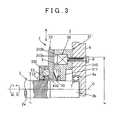
- FIG. 3 is a cross-sectional view illustrating a generation status of rolling friction force of a cam follower in the electromagnetic clutch as a clutch device according to the embodiment of the present invention.
- FIG. 4 is a view taken along an arrow A in FIG. 3 .
- FIG. 5 is a cross-sectional view schematically illustrated to introduce a conditional equation for setting a desired cam angle in FIGS. 3 and 4 .
- FIG. 1 illustrates a drive status of the electromagnetic clutch
- FIG. 2 illustrates a non-drive status of the electromagnetic clutch
- the electromagnetic clutch 1 is constituted of mainly a rotating member 2 which is rotated together with an input axis (not illustrated), an output mechanism 3 which is arranged on a rotation axis line O of the rotating member 2 as a clutch mechanism, and a cam mechanism 4 which is operated by an output of the output mechanism 3 to convert a rotation force from the rotating member 2 to a thrust force in a direction of the rotation axis line O.
- the electromagnetic clutch 1 functions as a braking device for braking the rotating member 2 with respect to a casing 6 which serves as a non-rotating member and is used, for example, when switching a torque transmission path by means of a planetary gear system (not illustrated).
- the casing 6 is provided with a shaft hole 6 a which is open in an inner surface thereof.
- the rotating member 2 is constituted of a solid round shaft including two large and small body portions 2 a , 2 b each having a different outside diameter from each other, connected to a motor shaft (input shaft) of an electric motor (not illustrated) via a reduction gear mechanism (not illustrated), and supported rotatably by the shaft hole 6 a (only one side illustrated) in the casing 6 via a bearing 7 .
- the rotating member 2 is constructed to be rotated together with the input shaft by driving of the electric motor.
- the large-diameter body portion 2 a has a straight spline-fitting portion 20 a , which is located on one side (electric motor side) of the rotating member 2 .
- the small-diameter body portion 2 b is arranged on the other side (casing 6 side) of the rotating member 2 and is consecutive from the large-diameter body portion 2 a.
- the output mechanism 3 includes a coil housing 31 which is a friction engagement member capable of rotating relative to the rotating member 2 , an electromagnetic coil 32 for generating electromagnetic force within the coil housing 31 , and an armature 33 which is a clutch member which is moved when the electromagnetic coil 32 is powered.
- the output mechanism 3 is arranged around the outer periphery of the rotating member 2 .
- the output mechanism 3 generates electromagnetic force as pressing force P 1 to the coil housing 31 using the electromagnetic coil 32 and outputs a moving force to move the armature 33 .
- the coil housing 31 includes a coil holder 310 and an internal flange 311 which serve as a yoke, and is formed of an annular member which is fixed to the casing 6 with a fitting bolt 8 and through which the rotating member 2 passes.
- the coil holder 310 has an annular coil accommodation portion 310 a which is open to the armature 33 side and arranged in the outer periphery of the coil housing 31 .
- the coil holder 310 has a friction face 310 b which is oriented to an end face on the coil housing 31 side of the armature 33 .
- the internal flange 311 is disposed in the inner periphery side of the coil housing 31 and formed integrally with the inner peripheral face of the coil holder 310 .
- the electromagnetic coil 32 is accommodated in the coil accommodation portion 310 a of the coil housing 31 such that it is opposed to the armature 33 and stopped from being loose by a retaining ring 9 . Then, the electromagnetic coil 32 is so constructed to form an electromagnetic circuit M across the armature 33 and the coil housing 31 when powered.
- the armature 33 has a friction face 33 a opposed to the friction face 310 b of the coil housing 31 and is arranged on the side of the cam mechanism 4 of the output mechanism 3 such that it is capable of rotating and moving relative to the rotating member 2 .
- the armature 33 is formed entirely of an annular member through which the rotating member 2 passes.
- the armature 33 is moved in the direction of the axis line by an output of the output mechanism 3 so that the friction face 33 a gets into a frictional engagement with the friction face 310 b of the coil housing 31 due to the pressing force P 1 .
- the armature 33 has a cam groove 330 which is open in an end face opposite to the end face on the coil housing side of the output mechanism 3 and functions as a component of the cam mechanism 4 together with a control cam 41 (described below) and a cam follower 42 (described below).
- a control cam 41 (described below)
- a cam follower 42 (described below).
- the cam groove 330 is formed such that the depth thereof in the direction of the axis line changes along the circumference of the armature 33 .
- the armature 33 is always supplied with restoration force in a direction in which the armature 33 departs (separates) from the electromagnetic coil 32 by a restoration spring 10 .
- the restoration spring 10 is formed of, for example, a disc spring and interposed between a bearing 11 on the coil housing 31 (internal flange 311 ) and the armature 33 while arranged around the outer periphery of the rotating member 2 .
- the cam mechanism 4 has the control cam 41 which serves as a cam member and the cam follower 42 which is interposed between the control cam 41 and the armature 33 and is arranged around the outer periphery of the rotating member 2 .
- the control cam 41 has a straight-spline-fitting portion 41 a which corresponds to the straight-spline-fitting portion 20 a in the rotating member 2 .
- the control cam 41 is arranged on the large-diameter body portion 2 a of the rotating member 2 on the electric motor side of the cam mechanism 4 such that it is incapable of rotating relative to the large-diameter body portion 2 a and capable of moving relative thereto. Additionally, the control cam 41 is restricted from moving in one direction of the axis line (to the electric motor) by a retaining ring 12 .
- the control cam 41 is provided with a cam groove 410 which is open to the cam follower 42 side.
- the cam groove 410 is formed of a concave groove whose depth in the direction of the axis line changes along the circumference of the control cam 41 .
- the cam follower 42 is formed of a spherical member and interposed between the cam groove 410 in the control cam 41 and the cam groove 330 in the armature 33 such that it is capable of rolling.
- the cam follower 42 is held by a retainer 13 .
- the retainer 13 is provided with a ball holding hole 13 a for holding the cam follower 42 such that it is capable of rolling.
- FIG. 3 illustrates an operating condition of the cam mechanism.
- FIG. 4 illustrates each cam groove in the armature and the control cam.
- the cam groove 330 is formed of a concave groove whose depth in the direction of the axis line of the armature 33 decreases gradually from a central portion a in the circumferential direction where the depth is the largest toward end portions b, c in the circumferential direction.
- the groove bottom is formed of a cam surface 330 a , existing between the central portion a in the circumferential direction and the end portion b in the circumferential direction, and a cam surface 330 b existing between the central portion a in the circumferential direction and the end portion c in the circumferential direction.
- the cam follower 42 When the electromagnetic coil 32 is not powered, the cam follower 42 is disposed in the central portion a in the circumferential direction of the cam groove 330 .
- the cam follower 42 rolls so that torsional force Fc is applied to the armature 33 .
- Cam surfaces 330 a , 330 b are formed of a slope having a cam angle ⁇ (an inclination angle ⁇ with respect to a plane perpendicular to the rotation axis line O) which rises from the central portion a in the circumferential direction toward the end portions b, c in the circumferential direction (such that the thickness of the armature 33 increases in the width direction of the armature 33 from the central portion a in the circumferential direction toward the end portions b, c in the circumferential direction).
- a cam angle ⁇ an inclination angle ⁇ with respect to a plane perpendicular to the rotation axis line O
- the cam groove 410 is formed of a concave groove whose depth in the direction of the axis line of the control cam 41 decreases gradually from the central portion a in the circumferential direction where the depth is the largest toward the end portions b, c in the circumferential direction.
- the groove bottom is formed of a cam surface 410 a existing between the central portion a in the circumferential direction and the end portion b in the circumferential direction and a cam surface 410 b existing between the central portion a in the circumferential direction and the end portion c in the circumferential direction.
- the cam follower 42 When the electromagnetic coil 32 is not powered, the cam follower 42 is disposed in the central portion a in the circumferential direction of the cam groove 410 .
- the cam follower 42 rolls so that the torsional force Fc is applied to the control cam 41 .
- Cam surfaces 410 a , 410 b are formed of a slope having a cam angle ⁇ (an inclination angle ⁇ with respect to a plane perpendicular to the rotation axis line O) which rises from the central portion a in the circumferential direction toward the end portions b, c in the circumferential direction (such that the thickness of the control cam 41 increases in the width direction of the control cam 41 from the central portion a in the circumferential direction toward the end portions b, c in the circumferential direction).
- a cam angle ⁇ an inclination angle ⁇ with respect to a plane perpendicular to the rotation axis line O
- the cam angle ⁇ is set to such an angle that intensifies torque T2 (T1 ⁇ T2: not indicated) applied to the armature 33 with reaction force Fp accompanying the friction engagement with the electromagnetic coil 32 with respect to the torque T1 (not indicated) applied to the armature 33 due to the thrust force F caused by activation of the cam mechanism 4 .
- the thrust force generated in the armature 33 due to the activation of the cam mechanism 4 is F
- the coefficient of static friction of the armature 33 to the friction face 310 b of the electromagnetic coil 32 is ⁇ m (e.g., ⁇ m ⁇ 0.1 to 0.15)
- the coefficient of rolling friction of the cam follower 42 to the armature 33 is ⁇ c (e.g., 0 ⁇ c ⁇ 0.02)
- the radius of an equivalent friction circle of the armature 33 is rm
- the radius of an action circle of the cam follower 42 is rc
- FIG. 5 illustrates a state in which the torsional force Fc is applied to the armature 33 when supply of electricity to the electromagnetic coil 32 is stopped.
- the thrust force F transmission torque capacity
- the electromagnetic coil 32 of the output mechanism 3 is supplied with no electricity, no magnetic circuit M originating from the electromagnetic coil 32 is formed. Thus, the armature 33 is never attracted to the electromagnetic coil 32 via the coil housing 31 .
- the magnetic circuit M is formed from the electromagnetic coil 32 , so that the armature 33 is moved from its initial position toward the coil holder 310 in the coil housing 31 .
- the cam angle ⁇ of each of the cam surfaces 330 a , 330 b of the armature 33 and the cam surfaces 410 a , 410 b of the control cam 41 is set to such an angle that satisfies ⁇ m ⁇ rm ⁇ F ⁇ F ⁇ rc ⁇ (sin ⁇ c cos ⁇ )/(cos ⁇ + ⁇ c sin ⁇ ) in order to smooth the rolling of the cam follower 42 . Therefore, the rolling of the cam follower 42 on the cam surfaces 330 a , 330 b , 410 a , 410 b is never obstructed. This phenomenon has been verified by a number of experiments.
- T1 frequency torque applied to the armature by the cam thrust force
- T2 torque applied to the armature by the reaction force
- the thrust force of the cam mechanism can be increased as much as possible with a condition for the self-release characteristic of the armature satisfied, it is possible to avoid restricting of the clutch device capacity excessively. That is, because the cam thrust force decreases when the cam angle is increased, a countermeasure such as increasing the size of the clutch device and increasing coil current is necessary to compensate for a decrease in the cam thrust force. According to the present embodiment, the increase in size of the clutch device and the increase in consumption power due to such a countermeasure can be suppressed.
- control cam 41 is arranged on the rotating member 2 such that it is capable of moving relative thereto and incapable of rotating relative thereto.
- the present invention is not restricted to this example, but the control cam may be arranged on the rotating member such that it is incapable of moving relative thereto and incapable of rotating relative thereto.
- an indispensable condition of the present invention is just that the control cam is incapable of rotating relative to the rotating member.
- the present invention is not restricted to this example, but the present invention may be applied to a clutch device using other locking force, for example, oil pressure or water pressure.
- the present invention is not restricted to this example, but the clutch device of the present invention may be made to function as a drive force transmission device for transmitting drive torque between a pair of the rotating members.
Abstract
Description
Claims (4)
Applications Claiming Priority (2)
| Application Number | Priority Date | Filing Date | Title |
|---|---|---|---|
| JP2011-226014 | 2011-10-13 | ||
| JP2011226014A JP5951215B2 (en) | 2011-10-13 | 2011-10-13 | Clutch device |
Publications (2)
| Publication Number | Publication Date |
|---|---|
| US20130092502A1 US20130092502A1 (en) | 2013-04-18 |
| US8899396B2 true US8899396B2 (en) | 2014-12-02 |
Family
ID=47080301
Family Applications (1)
| Application Number | Title | Priority Date | Filing Date |
|---|---|---|---|
| US13/650,630 Expired - Fee Related US8899396B2 (en) | 2011-10-13 | 2012-10-12 | Clutch device |
Country Status (4)
| Country | Link |
|---|---|
| US (1) | US8899396B2 (en) |
| EP (1) | EP2581618B1 (en) |
| JP (1) | JP5951215B2 (en) |
| CN (1) | CN103047314B (en) |
Families Citing this family (9)
| Publication number | Priority date | Publication date | Assignee | Title |
|---|---|---|---|---|
| CN104141710B (en) * | 2014-07-25 | 2016-06-15 | 中国一冶集团有限公司 | A kind of electromagnetic clutch coil housing fixing means |
| CN107061688A (en) * | 2016-01-13 | 2017-08-18 | 株式会社捷太格特 | Differential gear |
| JP6735180B2 (en) * | 2016-03-04 | 2020-08-05 | ジーケーエヌ オートモーティブ リミテッド | A cam mechanism and a clutch device using this cam mechanism. |
| EP3586025A1 (en) * | 2017-02-21 | 2020-01-01 | Linamar Corporation | Self-energizing electromagnetic disconnect actuator |
| CN112352114B (en) * | 2018-07-02 | 2022-02-15 | 吉凯恩汽车有限公司 | Friction clutch device |
| US11285991B2 (en) * | 2019-07-22 | 2022-03-29 | Steering Solutions Ip Holding Corporation | Electromagnetic damping system for steering system |
| JP7136058B2 (en) * | 2019-10-08 | 2022-09-13 | トヨタ自動車株式会社 | Electromagnetic brake device |
| CN110782753A (en) * | 2019-11-09 | 2020-02-11 | 上海图菱新能源科技有限公司 | Electromagnetic motion experiment system and method |
| DE102019132229B3 (en) * | 2019-11-28 | 2021-05-27 | Schaeffler Technologies AG & Co. KG | Magnetic coupling with a rotation axis for actuating a separating coupling |
Citations (6)
| Publication number | Priority date | Publication date | Assignee | Title |
|---|---|---|---|---|
| FR2352212A1 (en) | 1976-05-17 | 1977-12-16 | Facet Enterprises | ELECTROMAGNETIC-ACTUATED TORQUE TRANSMISSION DEVICE |
| JP2003254352A (en) | 2002-03-05 | 2003-09-10 | Tochigi Fuji Ind Co Ltd | Electromagnetic clutch device |
| JP2005263208A (en) | 2005-03-14 | 2005-09-29 | Toyoda Mach Works Ltd | Vehicle drive device |
| JP2010208584A (en) | 2009-03-12 | 2010-09-24 | Toyota Motor Corp | Controller for hybrid vehicle |
| WO2010119551A1 (en) * | 2009-04-16 | 2010-10-21 | トヨタ自動車株式会社 | Controller of hybrid vehicle |
| JP2011144835A (en) | 2010-01-12 | 2011-07-28 | Jtekt Corp | Cam mechanism and electromagnetic clutch |
Family Cites Families (6)
| Publication number | Priority date | Publication date | Assignee | Title |
|---|---|---|---|---|
| JPH09108981A (en) * | 1995-10-20 | 1997-04-28 | Honda Motor Co Ltd | Locking member, and spanwork type actuator using it |
| JP4072234B2 (en) * | 1998-03-20 | 2008-04-09 | Gkn ドライブライン トルクテクノロジー株式会社 | Clutch device |
| SE0104244L (en) * | 2001-12-17 | 2002-11-12 | Scania Cv Abp | Building system for synchronization devices for a gearbox |
| JP2004009748A (en) * | 2002-06-03 | 2004-01-15 | Toyoda Mach Works Ltd | Power transmission device |
| JP2004232807A (en) * | 2003-01-31 | 2004-08-19 | Hitachi Unisia Automotive Ltd | Start clutch for idling stop vehicle |
| JP2012122563A (en) * | 2010-12-09 | 2012-06-28 | Toyota Motor Corp | Engagement device |
-
2011
- 2011-10-13 JP JP2011226014A patent/JP5951215B2/en not_active Expired - Fee Related
-
2012
- 2012-10-11 EP EP12188103.1A patent/EP2581618B1/en not_active Not-in-force
- 2012-10-12 CN CN201210385847.7A patent/CN103047314B/en not_active Expired - Fee Related
- 2012-10-12 US US13/650,630 patent/US8899396B2/en not_active Expired - Fee Related
Patent Citations (8)
| Publication number | Priority date | Publication date | Assignee | Title |
|---|---|---|---|---|
| FR2352212A1 (en) | 1976-05-17 | 1977-12-16 | Facet Enterprises | ELECTROMAGNETIC-ACTUATED TORQUE TRANSMISSION DEVICE |
| US4079821A (en) | 1976-05-17 | 1978-03-21 | Facet Enterprises, Inc. | Electromagnetic clutch |
| JP2003254352A (en) | 2002-03-05 | 2003-09-10 | Tochigi Fuji Ind Co Ltd | Electromagnetic clutch device |
| JP2005263208A (en) | 2005-03-14 | 2005-09-29 | Toyoda Mach Works Ltd | Vehicle drive device |
| JP2010208584A (en) | 2009-03-12 | 2010-09-24 | Toyota Motor Corp | Controller for hybrid vehicle |
| WO2010119551A1 (en) * | 2009-04-16 | 2010-10-21 | トヨタ自動車株式会社 | Controller of hybrid vehicle |
| US8469859B2 (en) * | 2009-04-16 | 2013-06-25 | Toyota Jidosha Kabushiki Kaisha | Control apparatus for hybrid vehicle |
| JP2011144835A (en) | 2010-01-12 | 2011-07-28 | Jtekt Corp | Cam mechanism and electromagnetic clutch |
Non-Patent Citations (1)
| Title |
|---|
| Extended European Search Report issued Jul. 9, 2014 in Patent Application No. 12188103.1. |
Also Published As
| Publication number | Publication date |
|---|---|
| CN103047314A (en) | 2013-04-17 |
| JP2013087792A (en) | 2013-05-13 |
| EP2581618A3 (en) | 2014-08-06 |
| EP2581618B1 (en) | 2018-10-03 |
| EP2581618A2 (en) | 2013-04-17 |
| US20130092502A1 (en) | 2013-04-18 |
| CN103047314B (en) | 2016-12-21 |
| JP5951215B2 (en) | 2016-07-13 |
Similar Documents
| Publication | Publication Date | Title |
|---|---|---|
| US8899396B2 (en) | Clutch device | |
| US9145930B2 (en) | Electromagnetic engagement apparatus | |
| JP5672976B2 (en) | Electromagnetic clutch | |
| US20080261773A1 (en) | Selective Freewheeling Mechanism and Electromechanical Vehicle Brake Having A Selective Freewheeling Mechanism | |
| JP2020012554A (en) | Clutch device | |
| JP2007205572A (en) | Wrap spring clutch | |
| JP2005008073A (en) | Failsafe mechanism of by-wire steering system and a by-wire steering system | |
| EP2581619A2 (en) | Electromagnetic clutch | |
| JP2005325908A (en) | Rotation transmitting device | |
| JP2019058032A (en) | Electric actuator | |
| JP2012062937A (en) | Electromagnetic clutch, and driving force transmission device equipped therewith | |
| WO2020009192A1 (en) | Clutch device | |
| JP5942003B2 (en) | clutch | |
| JP4541178B2 (en) | Rotation transmission device | |
| JP5753003B2 (en) | clutch | |
| JP2006226366A (en) | Rotation transmission device | |
| WO2020138162A1 (en) | Braking device, vehicle wheel module, and movement mechanism | |
| JP5421208B2 (en) | Press member return urging structure and power transmission device | |
| JP2006336729A (en) | Rotation transmission device | |
| JP2012107732A (en) | Electromagnetic clutch | |
| JP2007303507A (en) | Power transmission device for hybrid car | |
| JP2018141530A (en) | Engagement device | |
| JP2010091045A (en) | Cam mechanism and power transmission device | |
| JP2006022881A (en) | Coupling device | |
| JP2008057673A (en) | Rotative power transmitting device |
Legal Events
| Date | Code | Title | Description |
|---|---|---|---|
| AS | Assignment |
Owner name: JTEKT CORPORATION, JAPAN Free format text: ASSIGNMENT OF ASSIGNORS INTEREST;ASSIGNORS:ONITAKE, MINORU;TAKUNO, HIROSHI;HOSOKAWA, TAKASHI;AND OTHERS;REEL/FRAME:029567/0660 Effective date: 20121121 Owner name: TOYOTA JIDOSHA KABUSHIKI KAISHA, JAPAN Free format text: ASSIGNMENT OF ASSIGNORS INTEREST;ASSIGNORS:ONITAKE, MINORU;TAKUNO, HIROSHI;HOSOKAWA, TAKASHI;AND OTHERS;REEL/FRAME:029567/0660 Effective date: 20121121 |
|
| STCF | Information on status: patent grant |
Free format text: PATENTED CASE |
|
| MAFP | Maintenance fee payment |
Free format text: PAYMENT OF MAINTENANCE FEE, 4TH YEAR, LARGE ENTITY (ORIGINAL EVENT CODE: M1551) Year of fee payment: 4 |
|
| FEPP | Fee payment procedure |
Free format text: MAINTENANCE FEE REMINDER MAILED (ORIGINAL EVENT CODE: REM.); ENTITY STATUS OF PATENT OWNER: LARGE ENTITY |
|
| LAPS | Lapse for failure to pay maintenance fees |
Free format text: PATENT EXPIRED FOR FAILURE TO PAY MAINTENANCE FEES (ORIGINAL EVENT CODE: EXP.); ENTITY STATUS OF PATENT OWNER: LARGE ENTITY |
|
| STCH | Information on status: patent discontinuation |
Free format text: PATENT EXPIRED DUE TO NONPAYMENT OF MAINTENANCE FEES UNDER 37 CFR 1.362 |
|
| FP | Lapsed due to failure to pay maintenance fee |
Effective date: 20221202 |