WO2020138102A1 - 飲料供給システムの洗浄装置 - Google Patents
飲料供給システムの洗浄装置 Download PDFInfo
- Publication number
- WO2020138102A1 WO2020138102A1 PCT/JP2019/050672 JP2019050672W WO2020138102A1 WO 2020138102 A1 WO2020138102 A1 WO 2020138102A1 JP 2019050672 W JP2019050672 W JP 2019050672W WO 2020138102 A1 WO2020138102 A1 WO 2020138102A1
- Authority
- WO
- WIPO (PCT)
- Prior art keywords
- cleaning
- gas
- flow path
- beverage
- flow
- Prior art date
- Legal status (The legal status is an assumption and is not a legal conclusion. Google has not performed a legal analysis and makes no representation as to the accuracy of the status listed.)
- Ceased
Links
Images

Classifications
-
- B—PERFORMING OPERATIONS; TRANSPORTING
- B67—OPENING, CLOSING OR CLEANING BOTTLES, JARS OR SIMILAR CONTAINERS; LIQUID HANDLING
- B67D—DISPENSING, DELIVERING OR TRANSFERRING LIQUIDS, NOT OTHERWISE PROVIDED FOR
- B67D1/00—Apparatus or devices for dispensing beverages on draught
- B67D1/07—Cleaning beverage-dispensing apparatus
-
- B—PERFORMING OPERATIONS; TRANSPORTING
- B67—OPENING, CLOSING OR CLEANING BOTTLES, JARS OR SIMILAR CONTAINERS; LIQUID HANDLING
- B67D—DISPENSING, DELIVERING OR TRANSFERRING LIQUIDS, NOT OTHERWISE PROVIDED FOR
- B67D1/00—Apparatus or devices for dispensing beverages on draught
- B67D1/08—Details
- B67D1/12—Flow or pressure control devices or systems, e.g. valves, gas pressure control, level control in storage containers
- B67D1/1202—Flow control, e.g. for controlling total amount or mixture ratio of liquids to be dispensed
- B67D1/1204—Flow control, e.g. for controlling total amount or mixture ratio of liquids to be dispensed for ratio control purposes
- B67D1/1206—Flow detectors
-
- B—PERFORMING OPERATIONS; TRANSPORTING
- B67—OPENING, CLOSING OR CLEANING BOTTLES, JARS OR SIMILAR CONTAINERS; LIQUID HANDLING
- B67D—DISPENSING, DELIVERING OR TRANSFERRING LIQUIDS, NOT OTHERWISE PROVIDED FOR
- B67D1/00—Apparatus or devices for dispensing beverages on draught
- B67D2001/0093—Valves
Definitions
- the present invention relates to a cleaning device for a beverage supply system for cleaning a pipeline of the beverage supply system.
- Beverage supply systems that use the pressure of the gas filled in the cylinder to dispense beverages such as beer stored in the beverage storage container are widely used in restaurants and the like.
- Such a beverage supply system is usually a gas cylinder and a beverage storage container, in addition to a dispense head attached to the mouth of the beverage storage container, a beverage dispenser for pouring the beverage into a glass or the like, and a pipe line connecting them. Is equipped with.
- the pipeline through which the beverage is distributed needs to be regularly washed to maintain hygiene and flavor of the beverage.
- the dispensing head is usually removed from the beverage storage container, but the cited document 1 describes a configuration in which the pipe line can be cleaned while the dispensing head is attached to the beverage storage container in order to facilitate cleaning. ing.
- the cleaning liquid is supplied only when the dispense head is in the cleaning mode, the fluid to be supplied is selected based on the signal of the tilt sensor attached to the operation lever of the dispense head. It is configured.
- the dispense head may be placed in an environment where it may be soiled or watered by drinks, so there is concern that the probability of failure due to liquid adhesion to electronic components such as the tilt sensor may increase. It is also considered not easy to wire the signal line between the tilt sensor attached to the movable operation lever of the dispense head that is repeatedly attached to and detached from the beverage storage container and the controller that communicates with the tilt sensor.
- An object of the present invention is to provide a cleaning device for a beverage supply system, which can prevent the cleaning liquid from being accidentally supplied to the inside of the beverage storage container while solving the above-mentioned drawbacks.
- a first flow path for circulating a gas from a gas supply source the first flow path being connected to a fluid inlet of a dispense head mounted on a beverage storage container.
- At least one electromagnetic valve that independently opens and closes the flow path and the second flow path; a detector for measuring the flow rate of gas; and a control unit that is communicable with the detector and that operates the electromagnetic valve.
- the control unit determines whether or not cleaning is possible based on the measured gas flow rate, and when it is determined that cleaning is possible, closes the first flow path and opens the second flow path.
- a cleaning device for a beverage supply system is provided in which a cleaning liquid is circulated and the second flow path is not opened when it is determined that cleaning cannot be performed.
- a cleaning device for a beverage supply system having a completely new configuration, which determines whether or not cleaning is possible based on the flow rate of gas flowing through the pipeline of the beverage supply system. Further, according to this, it is not necessary to attach a sensor or the like to the dispensing head, and since it can be realized as an apparatus integrated in one housing including a detector, a cleaning apparatus with high operation reliability is realized. it can.
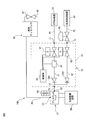
- FIG. 1 is a schematic configuration diagram of a cleaning device according to an embodiment of the present invention and a beverage supply system including the same. It is a schematic block diagram of a beverage supply system which also shows the internal structure of the washing
- the beverage supply system 100 includes a cleaning device (hereinafter, also referred to as a “cleaning device”) 10, a beverage storage container 50, a dispense head 51 attached to the beverage storage container 50, a dispense head 51, and a dispense head 51.
- a cleaning device hereinafter, also referred to as a “cleaning device”
- the beverage dispenser 60 has a cock-type beverage dispensing valve (hereinafter referred to as “cock valve”) 61.
- cock valve cock-type beverage dispensing valve
- a glass or the like (not shown) is prepared below the discharge port 62 of the cock valve 61 when the beverage is poured.
- a bucket 90 for receiving drainage is prepared below the discharge port 62 of the cock valve 61.
- the dispensing head 51 and the beverage dispenser 60 are connected by the fourth connection pipe line P4.
- the fourth connection pipeline P4 is connected to the cooling pipe 64 of the beverage dispenser 60, and the tip of the cooling pipe 64 is connected to the cock valve 61.
- the cooling pipe 64 has a spiral winding portion formed in a cylindrical coil shape for cooling the cooling pipe 64.
- the beverage dispenser 60 normally has a cooling device 65 and a cooling water tank 63 cooled by the cooling device 65, and the spiral winding portion of the cooling pipe 64 is cooled in the cooling water tank 63.
- the beverage to be supplied is beer, so that the gas filled in the gas cylinder 70 is carbon dioxide, the beverage storage container 50 is exemplified as a beer barrel, and the beverage dispenser 60 is beer. It is exemplified as a dispenser.
- the washing apparatus 10 is made of any carbonated beverage other than beer, for example, sparkling liquor, beer-flavored sparkling alcoholic beverage mixed with another alcoholic beverage (third Of beer), non-alcoholic beer, chu-hi, highball, or non-alcoholic carbonated beverages.
- the beverage supplied by the beverage supply system 100 may be a beverage supplied by using, for example, nitrogen gas or compressed air other than carbon dioxide gas, and in that case, nitrogen gas or compressed air is contained in the gas cylinder 70. Is filled.
- the internal flow path (not shown) of the dispense head 51, the fourth connection pipeline P4, and the cooling pipe 64 of the beverage dispenser 60 are the flow channels for the beverage and are used for cleaning. It is also the flow path for the cleaning liquid.
- the dispensing head 51 normally cooperates with a spear valve (not shown) fixedly mounted inside the beverage storage container 50 to introduce high-pressure gas from the gas cylinder 70 into the beverage storage container 50, It is provided for pumping the beverage in the beverage storage container 50 to the beverage dispenser 60 based on the gas pressure. Therefore, the dispense head 51, in its beverage supply mode, opens its own fluid inlet 52 and moves its plunger (not shown) to move the spear valve's gas inlet and beverage outlet (both not shown). To discharge the beverage from the fluid outlet 53. In its closed mode, the dispense head 51 retracts the plunger to close the gas inlet and the beverage outlet of the spear valve.
- a spear valve (not shown) fixedly mounted inside the beverage storage container 50 to introduce high-pressure gas from the gas cylinder 70 into the beverage storage container 50, It is provided for pumping the beverage in the beverage storage container 50 to the beverage dispenser 60 based on the gas pressure. Therefore, the dispense head 51, in its beverage supply mode, opens its own fluid inlet 52 and moves its plunger (
- the dispensing head 51 is provided with an operating lever 54 for moving a plunger (not shown). Normally, the beverage feeding position in which the operating lever 54 is pushed down and the closed position in which the operating lever 54 is pulled up are the beverage feeding mode and the closed state. Corresponds to each mode. Note that normally, during the business hours of the restaurant, the dispensing head 51 is kept in the beverage supply mode, and thus the supply and stop of the beverage are performed by opening and closing the cock valve 61 of the beverage dispenser 60. The closed mode of the dispense head 51 is required, for example, when the beverage storage container 50 is replaced.
- the dispensing head 51 of the beverage supply system 100 shown in FIG. 1 has a cleaning mode in addition to the beverage supply mode and the closed mode.
- the cleaning mode is such that the gas or cleaning liquid is introduced from the fluid inlet 52 of the dispense head 51 but not into the beverage storage container 50 and is discharged from the fluid outlet 53 toward the beverage dispenser 60.
- the operating lever 54 in the washing mode is arranged in a washing position which is a specific intermediate position between the upper position of the closing mode and the lower position of the beverage supply mode.
- the dispense head 51 When cleaning the fourth connection conduit P4 and the cooling pipe 64 of the beverage dispenser 60, the dispense head 51 must be set to the cleaning mode. If the cleaning liquid is supplied to the fluid inlet 52 of the dispense head 51 while the beverage supply mode is set, the cleaning liquid will flow into the beverage storage container 50.
- a cleaning apparatus 10 for a beverage supply system according to the first embodiment of the present invention that can prevent this problem will be described below.
- the cleaning device 10 of the beverage supply system includes a first inlet 11 connected to a gas cylinder 70 via a first connection pipe P1 and a second connection pipe connected to a water supply faucet 80. It has a second inlet 12 connected via the passage P2 and the pressure reducing valve RV, and a fluid outlet 13 on the side surface of the housing 14. The fluid outlet 13 is connected to the fluid inlet 52 of the dispense head 51 via a connection conduit P3.
- a display unit 15, a washing button 16, a beverage supply button 17, and a closing button 18 are arranged on the front surface of the housing 14.
- the cleaning device 10 includes a first electromagnetic valve V1 that opens and closes the first flow path 21, and a second electromagnetic valve V2 that opens and closes the second flow path 22.
- first solenoid valve V1 and the second solenoid valve V2 are separate in this embodiment, they may be replaced with one solenoid valve having the same function as those two solenoid valves.
- the cleaning device 10 further includes a first check valve CV1 arranged in the first flow passage 21 and a second check valve CV2 arranged in the second flow passage 22.
- the cleaning device 10 has a cleaning mode, a beverage supply mode, and a fully closed mode that can be selected by a cleaning button 16, a beverage supply button 17, and a closing button 18, respectively.
- the first flow path 21 is open, while the second flow path 22 is closed.
- the cleaning mode as will be described later in detail, the first flow path 21 is opened, then it is closed, and the second flow path 22 is opened.
- the fully closed mode both the first flow path 21 and the second flow path 22 are closed.
- the cleaning device 10 further includes a detector 23 for detecting the flow rate of the gas flowing through the first flow path 21.
- a detector 23 for detecting the flow rate of the gas flowing through the first flow path 21.
- a thermal type flow rate detector is used.
- another type of flow rate detector such as a differential pressure type, an ultrasonic type, a Karman vortex type, an impeller type, and a float type as the detector 23 is also possible in the present invention.
- a detector for detecting the flow velocity is used instead of the detector 23 for detecting the flow rate is also possible in the present invention.
- the detector 23 is arranged inside the housing 14 of the cleaning device 10, but may be arranged outside the housing 14 in the first connection conduit P1 from the gas cylinder 70. .. Further, if the detector 23 is of a water resistant type, it may be arranged in the third connecting pipe P3 reaching the dispensing head 51.
- the cleaning device 10 also includes a control unit 24.
- the controller 24 receives signals from the wash button 16, the beverage supply button 17, the close button 18, and the detector 23 to operate the first solenoid valve V1 and the second solenoid valve V2, and a processor (not shown). , A timer, a memory, and the like.
- the control unit 24 determines whether or not the cleaning is possible based on the gas flow rate measured by the detector 23, and when it is determined that the cleaning is possible, the first electromagnetic valve V1 is closed to close the first flow path. 21 is closed and the second electromagnetic valve V2 is opened to open the second flow path 22 to allow the cleaning liquid from the water tap 80 to flow, and when it is determined that cleaning is impossible, the valve is closed.
- the second solenoid valve V2 is kept closed, that is, the second flow path 22 is not opened. At this time, the control unit 24 also closes the first electromagnetic valve V1.
- the beverage supply mode is selected for the cleaning device 10, and thus the first flow path 21 for gas is open, but the second flow path 22 for cleaning liquid (water) is closed.
- the dispense head 51 is also in the beverage supply mode.
- the cock valve 61 is supplied from the gas cylinder 70, passes through the cleaning device 10, and is supplied into the beverage storage container 50 through the fluid inlet 52 of the dispense head 51.
- the beverage is pressure-fed from the beverage storage container 50 to the beverage dispenser 60 via the dispensing head 51 and discharged from the cock valve 61.
- the cock valve 61 is closed.
- the operation head 54 of the dispense head 51 When cleaning the fourth connection conduit P4 and the cooling pipe 64, which are beverage supply conduits, the operation head 54 of the dispense head 51 is placed at the cleaning position, the cleaning mode is selected, and the cleaning device 10 also cleans the same.
- the button 16 is pressed to select the cleaning mode.
- the cleaning device 10 in which the cleaning mode is selected initially, the first flow path 21 for gas is opened and the second flow path 22 for cleaning liquid is closed, as in the case where the beverage supply mode is selected. ing.
- the control unit 24 of the cleaning device 10 activates the timer from the time when the gas starts flowing, and displays the remaining time of the cleaning process on the display unit 15.
- the gas begins to flow, the beverage remains in the fourth connecting pipe P4 and the cooling pipe 64 and becomes a resistance, so that the flow rate of the gas is smaller than that in the case where the beverage is not present.
- the control unit 24 evaluates the flow rate of the gas obtained after the elapse of a predetermined time from the operation of the timer.
- the predetermined time is set as a time obtained by adding a margin to the time required for pushing out the beverage remaining in the fourth connecting pipe P4 and the cooling pipe 64. Therefore, if the dispense head 51 is correctly selected for the cleaning mode, the flow rate of gas should increase after the lapse of the predetermined time. Therefore, when the flow rate of the gas is equal to or more than a predetermined value, the control unit 24 determines that the cleaning is possible, closes the first electromagnetic valve V1 and closes the first flow path 21, and 2 The solenoid valve V2 is opened to open the second flow path 22. As a result, the cleaning liquid from the water tap 80 is supplied to the fourth connection conduit P4 and the cooling pipe 64 via the cleaning device 10 and the dispensing head 51.
- the control unit 24 closes the second flow path 22 to stop the supply of the cleaning liquid, and again the first flow path 21.
- the gas is resupplied in order to remove the water remaining in the fourth connecting pipe P4 and the like and dry the pipe.
- the control unit 24 closes the first flow path 21 and stops the gas supply.
- the remaining time of the cleaning process displayed on the display unit 15 becomes zero.
- the operator closes the cock valve 61 of the beverage dispenser 60 and places the operation lever 54 of the dispense head 51 at the beverage supply position or the closed position.
- the cleaning apparatus 10 in which the cleaning mode is selected initially opens the first flow passage 21 for gas and closes the second flow passage 22 for cleaning liquid.
- the gas starts flowing in the first flow path 21 of the cleaning device 10.
- the operating lever 54 of the dispense head 51 is set to the beverage supply position, the gas continues to pump the beverage, and therefore the flow rate of the gas is relatively high even when the above-mentioned predetermined time has elapsed since the timer was activated.
- the control unit 24 determines that the cleaning is not possible, and the first flow path 21 is determined. Is closed and the second flow path 22 is also kept closed. At this time, the control unit 24 also makes an alarm sound. As a result, the supply of cleaning liquid to the beverage storage container 50 is prevented and the operator should be aware that the operating lever 54 of the dispense head 51 is not located in the cleaning position.
- a cleaning device 10 for a beverage supply system having a completely new configuration in which whether or not cleaning is possible is determined based on the flow rate of gas flowing through the pipeline. According to the cleaning device 10, it is not necessary to attach a sensor or the like to the dispense head 51, and since the cleaning device 10 can be realized as a device integrated in one housing 14 including the detector 23, the operation reliability can be improved. A high cleaning device 10 can be realized.
- the cleaning device 10 (hereinafter, also referred to as “cleaning device”) 10 of the beverage supply system according to the second embodiment will be described.
- the cleaning apparatus 10 is different from that of the above-described first embodiment in the method of determining whether or not cleaning is possible, but other configurations are the same.
- the control unit 24 controls the initial flow rate measured when a relatively short first time elapses after the cleaning button 16 is operated and the gas starts flowing, and the gas flow rate. Compared with the late flow rate of the gas measured after the elapse of a predetermined second time, which is relatively long after the flow started, and when the late flow rate has increased by a predetermined ratio or more with respect to the initial flow rate, it is determined that cleaning is possible. However, when it is less than the predetermined magnification, it is determined that cleaning is impossible.
- the predetermined first time is set as a time included in the time zone in which the gas pushes out the beverage when the beverage remains in the fourth connecting pipeline P4.
- the predetermined second time is set as the same time as the predetermined time in the first embodiment. That is, the predetermined second time is a time obtained by adding a margin to the time required to push out the beverage remaining in the fourth connecting pipe P4 and the cooling pipe 64.
- beverage is beer
- alcoholic beverages such as highball, wine, sake, carbonated beverages such as cola and cider
- non-carbonated beverages such as juice
- Beverage Supply System Cleaning Device 11 First Inlet 12 Second Inlet 13 Fluid Outlet 15 Display 16 Cleaning Button 21 First Flow Path 22 Second Flow Path 23 Detector 24 Controller V1 First Solenoid Valve V2 Second solenoid valve 50 Beverage storage container 51 Dispensing head 60 Beverage dispenser 70 Gas cylinder 80 Water tap 100 Beverage supply system
Landscapes
- Devices For Dispensing Beverages (AREA)
Abstract
Description
通常は、洗浄装置10は飲料供給モードが選択され、したがってガス用の第1の流路21は開放されているが洗浄液(水)用の第2の流路22は閉鎖されている。このとき、ディスペンスヘッド51も飲料供給モードが選択されている。この状態で、操作者によって飲料ディスペンサ60のコック弁61が開弁されると、ガスボンベ70から供給されて洗浄装置10を通ってディスペンスヘッド51の流体入口52を介して飲料貯蔵容器50内に供給されるガスの圧力に基づいて、飲料が飲料貯蔵容器50からディスペンスヘッド51を経て飲料ディスペンサ60へ向けて圧送されそのコック弁61から吐出される。飲料の吐出を止めるにはコック弁61を閉弁する。
11 第1の入口
12 第2の入口
13 流体出口
15 表示部
16 洗浄ボタン
21 第1の流路
22 第2の流路
23 検出器
24 制御部
V1 第1電磁弁
V2 第2電磁弁
50 飲料貯蔵容器
51 ディスペンスヘッド
60 飲料ディスペンサ
70 ガスボンベ
80 給水栓
100 飲料供給システム
Claims (5)
- ガス供給源からのガスを流通させる第1の流路であって、飲料貯蔵容器に装着されたディスペンスヘッドの流体入口に接続される第1の流路と、
洗浄液供給源からの洗浄液を流通させる第2の流路であって、前記飲料貯蔵容器に装着された前記ディスペンスヘッドの前記流体入口に接続される第2の流路と、
前記第1の流路及び前記第2の流路をそれぞれ独立に開閉する少なくとも一つの電磁弁と、
前記ガスの流量を測定するための検出器と、
前記検出器と通信可能でありかつ前記電磁弁を操作する制御部と、
を具備し、
前記制御部は、測定された前記ガスの流量に基づいて洗浄の可否を判定し、洗浄可と判定した場合には前記第1の流路を閉鎖するとともに前記第2の流路を開放して前記洗浄液を流通させ、洗浄不可と判定した場合には前記第2の流路を開放しない、飲料供給システムの洗浄装置。 - 洗浄ボタンをさらに具備しており、
前記制御部は、前記洗浄ボタンが操作されかつ前記ガスが流動し始めたとき、前記流動し始めから所定の時間経過後に測定された前記ガスの流量が、所定の値以上であるとき、洗浄可と判定するのに対して、前記所定の値未満であるとき、洗浄不可と判定する、請求項1に記載の飲料供給システムの洗浄装置。 - 洗浄ボタンをさらに具備しており、
前記制御部は、前記洗浄ボタンが操作されかつ前記ガスが流動し始めたとき、前記流動し始めから比較的短い所定の第1の時間の経過時に測定された前記ガスの初期流量に対して、前記ガスの流動開始から比較的長い所定の第2の時間の経過後に測定された前記ガスの後期流量が、所定の倍率以上で増大したとき、洗浄可と判定するのに対して、前記所定の倍率未満であるとき、洗浄不可と判定する、請求項1に記載の飲料供給システムの洗浄装置。 - 前記第1の流路及び前記第2の流路が設けられ、前記制御部及び前記電磁弁を収容する
筐体をさらに具備しており、
前記検出器は、前記筐体の内部に収容されるか又は前記筐体の外部に配置される、請求項1~3のいずれか一項に記載の飲料供給システムの洗浄装置。 - 前記検出器が前記ガスの流量に代えて流速を測定するための検出器であり、
前記制御部は、測定された前記ガスの流速に基づいて洗浄の可否を判定する、請求項1~3のいずれか一項に記載の飲料供給システムの洗浄装置。
Priority Applications (3)
| Application Number | Priority Date | Filing Date | Title |
|---|---|---|---|
| CN201980086063.4A CN113260591A (zh) | 2018-12-28 | 2019-12-24 | 饮料供给系统的清洗装置 |
| KR1020217019182A KR20210092809A (ko) | 2018-12-28 | 2019-12-24 | 음료 공급 시스템의 세정 장치 |
| JP2020563317A JP7299922B2 (ja) | 2018-12-28 | 2019-12-24 | 飲料供給システムの洗浄装置 |
Applications Claiming Priority (2)
| Application Number | Priority Date | Filing Date | Title |
|---|---|---|---|
| JP2018248442 | 2018-12-28 | ||
| JP2018-248442 | 2018-12-28 |
Publications (1)
| Publication Number | Publication Date |
|---|---|
| WO2020138102A1 true WO2020138102A1 (ja) | 2020-07-02 |
Family
ID=71129482
Family Applications (1)
| Application Number | Title | Priority Date | Filing Date |
|---|---|---|---|
| PCT/JP2019/050672 Ceased WO2020138102A1 (ja) | 2018-12-28 | 2019-12-24 | 飲料供給システムの洗浄装置 |
Country Status (4)
| Country | Link |
|---|---|
| JP (1) | JP7299922B2 (ja) |
| KR (1) | KR20210092809A (ja) |
| CN (1) | CN113260591A (ja) |
| WO (1) | WO2020138102A1 (ja) |
Citations (2)
| Publication number | Priority date | Publication date | Assignee | Title |
|---|---|---|---|---|
| JP2012250767A (ja) * | 2011-05-06 | 2012-12-20 | Takashi Nitta | ビールディスペンサー洗浄方法及び洗浄装置 |
| WO2018212349A1 (ja) * | 2017-05-19 | 2018-11-22 | サントリーホールディングス株式会社 | ディスペンスヘッド及びそれを利用した飲料注出路の洗浄方法 |
Family Cites Families (13)
| Publication number | Priority date | Publication date | Assignee | Title |
|---|---|---|---|---|
| JP2525741B2 (ja) * | 1987-09-07 | 1996-08-21 | サントリー株式会社 | ディスペンサ―用サニテ―ションシステム |
| FI110237B (fi) * | 2000-06-06 | 2002-12-31 | Rescontrol Oy | Menetelmä ja järjestelmä juomien jakelulinjan pesemiseksi sekä järjestelmässä käytettävä tunnistinyksikkö |
| AUPR563301A0 (en) * | 2001-06-13 | 2001-07-12 | Ozone Manufacturing Pty Ltd | Beverage line purifier |
| JP4254642B2 (ja) | 2004-07-22 | 2009-04-15 | 富士電機リテイルシステムズ株式会社 | 飲料ディスペンサ |
| GB0504090D0 (en) * | 2005-02-28 | 2005-04-06 | Coffee Nation Ltd | Apparatus for preparing beverages |
| JP2006264696A (ja) * | 2005-03-22 | 2006-10-05 | Fuji Electric Retail Systems Co Ltd | 発泡飲料注出装置 |
| JP2006264716A (ja) * | 2005-03-23 | 2006-10-05 | Fic:Kk | ディスペンスヘッド、飲料通路洗浄装置 |
| NL1032098C2 (nl) * | 2006-06-30 | 2008-01-02 | Heineken Supply Chain Bv | Tapinrichting, drankcontainer, koppelingsinrichting en werkwijze met reinigingselement. |
| JP2008189326A (ja) * | 2007-02-01 | 2008-08-21 | Kirin Brewery Co Ltd | 飲料注出装置 |
| CN102874732B (zh) * | 2011-07-15 | 2015-07-15 | 赵建国 | 一种饮料分取机饮料出口清洗装置 |
| IN2015DN01769A (ja) * | 2012-08-30 | 2015-05-29 | Pepsico Inc | |
| KR102218579B1 (ko) * | 2015-12-08 | 2021-02-22 | 후지 덴키 가부시키가이샤 | 음료 공급 장치 |
| CN107473169B (zh) * | 2016-06-08 | 2020-08-04 | 三国总业株式会社 | 饮料供给路径的清洗方法以及清洗装置 |
-
2019
- 2019-12-24 JP JP2020563317A patent/JP7299922B2/ja active Active
- 2019-12-24 WO PCT/JP2019/050672 patent/WO2020138102A1/ja not_active Ceased
- 2019-12-24 KR KR1020217019182A patent/KR20210092809A/ko not_active Abandoned
- 2019-12-24 CN CN201980086063.4A patent/CN113260591A/zh active Pending
Patent Citations (2)
| Publication number | Priority date | Publication date | Assignee | Title |
|---|---|---|---|---|
| JP2012250767A (ja) * | 2011-05-06 | 2012-12-20 | Takashi Nitta | ビールディスペンサー洗浄方法及び洗浄装置 |
| WO2018212349A1 (ja) * | 2017-05-19 | 2018-11-22 | サントリーホールディングス株式会社 | ディスペンスヘッド及びそれを利用した飲料注出路の洗浄方法 |
Also Published As
| Publication number | Publication date |
|---|---|
| KR20210092809A (ko) | 2021-07-26 |
| JPWO2020138102A1 (ja) | 2021-11-11 |
| CN113260591A (zh) | 2021-08-13 |
| JP7299922B2 (ja) | 2023-06-28 |
Similar Documents
| Publication | Publication Date | Title |
|---|---|---|
| US5636763A (en) | Gas pressurized liquid delivery system | |
| US20220315407A1 (en) | Cleaning unit for supplying a cleaning liquid to a beverage dispensing system | |
| JP6808030B2 (ja) | ディスペンスヘッド及びそれを利用した飲料注出路の洗浄方法 | |
| US8657161B2 (en) | Beverages dispenser and a method for dispensing beverages | |
| RS56480B1 (sr) | Metoda i uređaj za detektovanje operativnog režima sistema za napitke | |
| JP7049191B2 (ja) | 飲料サーバーの洗浄装置 | |
| JP2007015766A (ja) | ディスペンスヘッドおよびそれを用いた発泡性飲料供給装置 | |
| JP7299922B2 (ja) | 飲料供給システムの洗浄装置 | |
| CN210973857U (zh) | 一种消除气泡装置及饮料机 | |
| JP7376589B2 (ja) | 飲料供給システムの洗浄装置及び飲料供給システムの洗浄方法 | |
| JP7263394B2 (ja) | 飲料サーバーの洗浄装置 | |
| JP2003054696A (ja) | 発泡飲料検出装置及びそれを用いた発泡飲料注出装置 | |
| EP1767489A2 (en) | IBeverage dispenser with purging means | |
| US12358773B2 (en) | Beverage dispensing and sanitizing system | |
| JP7580714B2 (ja) | 液体供給システム | |
| JP7349905B2 (ja) | 飲料供給システムの洗浄装置 | |
| GB2505903A (en) | Dispensing beverage left in dispense lines using pressurised gas | |
| GB2423980A (en) | Beverage dispense | |
| JP2006264696A (ja) | 発泡飲料注出装置 | |
| JP2020200066A (ja) | 飲料供給システム及び飲料枯渇通知方法 | |
| JP2006213327A (ja) | 液体センサーによる流体自動切替システム | |
| JPH09267898A (ja) | 清涼飲料水ディスペンサ |
Legal Events
| Date | Code | Title | Description |
|---|---|---|---|
| 121 | Ep: the epo has been informed by wipo that ep was designated in this application |
Ref document number: 19905327 Country of ref document: EP Kind code of ref document: A1 |
|
| ENP | Entry into the national phase |
Ref document number: 2020563317 Country of ref document: JP Kind code of ref document: A |
|
| ENP | Entry into the national phase |
Ref document number: 20217019182 Country of ref document: KR Kind code of ref document: A |
|
| NENP | Non-entry into the national phase |
Ref country code: DE |
|
| 122 | Ep: pct application non-entry in european phase |
Ref document number: 19905327 Country of ref document: EP Kind code of ref document: A1 |