WO2020137733A1 - フィルタ濾材、フィルタプリーツパック、フィルタユニット - Google Patents
フィルタ濾材、フィルタプリーツパック、フィルタユニット Download PDFInfo
- Publication number
- WO2020137733A1 WO2020137733A1 PCT/JP2019/049565 JP2019049565W WO2020137733A1 WO 2020137733 A1 WO2020137733 A1 WO 2020137733A1 JP 2019049565 W JP2019049565 W JP 2019049565W WO 2020137733 A1 WO2020137733 A1 WO 2020137733A1
- Authority
- WO
- WIPO (PCT)
- Prior art keywords
- filter medium
- medium layer
- filter
- layer
- breathable
- Prior art date
- Legal status (The legal status is an assumption and is not a legal conclusion. Google has not performed a legal analysis and makes no representation as to the accuracy of the status listed.)
- Ceased
Links
Images



Classifications
-
- B—PERFORMING OPERATIONS; TRANSPORTING
- B01—PHYSICAL OR CHEMICAL PROCESSES OR APPARATUS IN GENERAL
- B01D—SEPARATION
- B01D69/00—Semi-permeable membranes for separation processes or apparatus characterised by their form, structure or properties; Manufacturing processes specially adapted therefor
- B01D69/12—Composite membranes; Ultra-thin membranes
- B01D69/1213—Laminated layers
-
- A—HUMAN NECESSITIES
- A41—WEARING APPAREL
- A41D—OUTERWEAR; PROTECTIVE GARMENTS; ACCESSORIES
- A41D13/00—Professional, industrial or sporting protective garments, e.g. surgeons' gowns or garments protecting against blows or punches
- A41D13/05—Professional, industrial or sporting protective garments, e.g. surgeons' gowns or garments protecting against blows or punches protecting only a particular body part
- A41D13/11—Protective face masks, e.g. for surgical use, or for use in foul atmospheres
-
- A—HUMAN NECESSITIES
- A62—LIFE-SAVING; FIRE-FIGHTING
- A62B—DEVICES, APPARATUS OR METHODS FOR LIFE-SAVING
- A62B18/00—Breathing masks or helmets, e.g. affording protection against chemical agents or for use at high altitudes or incorporating a pump or compressor for reducing the inhalation effort
- A62B18/02—Masks
-
- B—PERFORMING OPERATIONS; TRANSPORTING
- B01—PHYSICAL OR CHEMICAL PROCESSES OR APPARATUS IN GENERAL
- B01D—SEPARATION
- B01D39/00—Filtering material for liquid or gaseous fluids
- B01D39/14—Other self-supporting filtering material ; Other filtering material
- B01D39/16—Other self-supporting filtering material ; Other filtering material of organic material, e.g. synthetic fibres
-
- B—PERFORMING OPERATIONS; TRANSPORTING
- B01—PHYSICAL OR CHEMICAL PROCESSES OR APPARATUS IN GENERAL
- B01D—SEPARATION
- B01D46/00—Filters or filtering processes specially modified for separating dispersed particles from gases or vapours
- B01D46/52—Particle separators, e.g. dust precipitators, using filters embodying folded corrugated or wound sheet material
-
- B—PERFORMING OPERATIONS; TRANSPORTING
- B01—PHYSICAL OR CHEMICAL PROCESSES OR APPARATUS IN GENERAL
- B01D—SEPARATION
- B01D63/00—Apparatus in general for separation processes using semi-permeable membranes
- B01D63/14—Pleat-type membrane modules
-
- B—PERFORMING OPERATIONS; TRANSPORTING
- B01—PHYSICAL OR CHEMICAL PROCESSES OR APPARATUS IN GENERAL
- B01D—SEPARATION
- B01D71/00—Semi-permeable membranes for separation processes or apparatus characterised by the material; Manufacturing processes specially adapted therefor
- B01D71/06—Organic material
- B01D71/26—Polyalkenes
- B01D71/262—Polypropylene
-
- B—PERFORMING OPERATIONS; TRANSPORTING
- B01—PHYSICAL OR CHEMICAL PROCESSES OR APPARATUS IN GENERAL
- B01D—SEPARATION
- B01D71/00—Semi-permeable membranes for separation processes or apparatus characterised by the material; Manufacturing processes specially adapted therefor
- B01D71/06—Organic material
- B01D71/30—Polyalkenyl halides
- B01D71/32—Polyalkenyl halides containing fluorine atoms
- B01D71/36—Polytetrafluoroethylene
-
- B—PERFORMING OPERATIONS; TRANSPORTING
- B01—PHYSICAL OR CHEMICAL PROCESSES OR APPARATUS IN GENERAL
- B01D—SEPARATION
- B01D71/00—Semi-permeable membranes for separation processes or apparatus characterised by the material; Manufacturing processes specially adapted therefor
- B01D71/06—Organic material
- B01D71/52—Polyethers
- B01D71/522—Aromatic polyethers
- B01D71/5222—Polyetherketone, polyetheretherketone, or polyaryletherketone
-
- B—PERFORMING OPERATIONS; TRANSPORTING
- B01—PHYSICAL OR CHEMICAL PROCESSES OR APPARATUS IN GENERAL
- B01D—SEPARATION
- B01D71/00—Semi-permeable membranes for separation processes or apparatus characterised by the material; Manufacturing processes specially adapted therefor
- B01D71/06—Organic material
- B01D71/66—Polymers having sulfur in the main chain, with or without nitrogen, oxygen or carbon only
- B01D71/68—Polysulfones; Polyethersulfones
-
- B—PERFORMING OPERATIONS; TRANSPORTING
- B32—LAYERED PRODUCTS
- B32B—LAYERED PRODUCTS, i.e. PRODUCTS BUILT-UP OF STRATA OF FLAT OR NON-FLAT, e.g. CELLULAR OR HONEYCOMB, FORM
- B32B27/00—Layered products comprising a layer of synthetic resin
- B32B27/30—Layered products comprising a layer of synthetic resin comprising vinyl (co)polymers; comprising acrylic (co)polymers
-
- B—PERFORMING OPERATIONS; TRANSPORTING
- B32—LAYERED PRODUCTS
- B32B—LAYERED PRODUCTS, i.e. PRODUCTS BUILT-UP OF STRATA OF FLAT OR NON-FLAT, e.g. CELLULAR OR HONEYCOMB, FORM
- B32B5/00—Layered products characterised by the non- homogeneity or physical structure, i.e. comprising a fibrous, filamentary, particulate or foam layer; Layered products characterised by having a layer differing constitutionally or physically in different parts
- B32B5/18—Layered products characterised by the non- homogeneity or physical structure, i.e. comprising a fibrous, filamentary, particulate or foam layer; Layered products characterised by having a layer differing constitutionally or physically in different parts characterised by features of a layer of foamed material
-
- B—PERFORMING OPERATIONS; TRANSPORTING
- B32—LAYERED PRODUCTS
- B32B—LAYERED PRODUCTS, i.e. PRODUCTS BUILT-UP OF STRATA OF FLAT OR NON-FLAT, e.g. CELLULAR OR HONEYCOMB, FORM
- B32B5/00—Layered products characterised by the non- homogeneity or physical structure, i.e. comprising a fibrous, filamentary, particulate or foam layer; Layered products characterised by having a layer differing constitutionally or physically in different parts
- B32B5/22—Layered products characterised by the non- homogeneity or physical structure, i.e. comprising a fibrous, filamentary, particulate or foam layer; Layered products characterised by having a layer differing constitutionally or physically in different parts characterised by the presence of two or more layers which are next to each other and are fibrous, filamentary, formed of particles or foamed
- B32B5/24—Layered products characterised by the non- homogeneity or physical structure, i.e. comprising a fibrous, filamentary, particulate or foam layer; Layered products characterised by having a layer differing constitutionally or physically in different parts characterised by the presence of two or more layers which are next to each other and are fibrous, filamentary, formed of particles or foamed one layer being a fibrous or filamentary layer
Definitions
- the present invention relates to a filter medium, a filter pleat pack, and a filter unit formed by using a fluororesin porous membrane.
- a filter medium using a porous membrane mainly composed of a fluororesin (hereinafter, also referred to as a fluororesin porous membrane) has been used. .. Since such a fluororesin porous membrane is relatively thin and has no stiffness, it may be difficult to use only the fluororesin porous membrane as a filter medium. Therefore, a filter medium has been proposed in which a porous fluororesin membrane is used as a first filter medium layer, and a second filter medium layer having air permeability is laminated on the first filter medium layer (see Patent Documents 1 and 2).
- the filter medium as described above, but for example, it may be used as a member that constitutes a mask that covers a person's mouth or nose.
- a mask is used to prevent particles and fungi in the air from being taken into the body by covering the mouth and nose, but by wearing one mask repeatedly, There is a risk that fungi and the like attached to the cells will grow. Wearing a mask in which fungi and the like proliferate in this manner causes the fungi and the like to invade the body and cause infections and the like. For this reason, a general mask is usually treated as a consumable item that is disposable only once.
- heating in such steam may significantly reduce the strength of the filter medium.
- the reduction in strength due to heating in water vapor may occur not only in the mask but also in the product using the filter medium.
- the inventors of the present invention have found that the strength of the filter medium is significantly reduced by the hydrolysis of the second filter medium layer when the filter medium is heated in water vapor, and have completed the present invention. ..
- the filter medium according to the present invention is formed into a sheet by laminating a first filter medium layer having air permeability and a second filter medium layer having air permeability, and one surface is formed by the first filter medium layer. Is formed, the other surface is formed by the second filter medium layer, the first filter medium layer is composed of a fluororesin porous membrane mainly composed of a fluororesin, the second filter medium layer is a breathable filter medium At least the surface of the member constituting the breathable filter medium is formed of an unhydrolyzed substance, and the unhydrolyzed substance is polypropylene, polyphenylene sulfide, polytetrafluoroethylene, polyether ketone, polyether ether ketone. At least one selected from the group consisting of polyether sulfone, polyphenylene ether, polysulfone, and polymethylpentene.
- the filter medium according to the present invention is formed into a sheet by laminating a first filter medium layer having air permeability and two second filter medium layers having air permeability, and the two second filter medium layers of the two One surface is formed by one, the other surface is formed by the other of the two second filter medium layers, the first filter medium layer is composed of a fluororesin porous film mainly composed of fluororesin,
- the two second filter medium layers are made of a breathable filter medium, and at least the surface of the member constituting the breathable filter medium is formed of an unhydrolyzed substance, and the unhydrolyzed substance is polypropylene, polyphenylene sulfide, or poly. It is at least one selected from the group consisting of tetrafluoroethylene, polyether ketone, polyether ether ketone, polyether sulfone, polyphenylene ether, polysulfone, and polymethylpentene.
- the fluororesin porous membrane is preferably a polytetrafluoroethylene porous membrane.
- the air-permeable filter medium is made of a non-woven fabric, and it is preferable that the fibers constituting the non-woven fabric are entirely made of non-hydrolyzable substance.
- the breathable filter medium is made of a non-woven fabric, each fiber that is a member constituting the non-woven fabric, has a tubular sheath portion and a core portion that fills the inside of the sheath portion,
- the sheath is preferably formed of a non-hydrolyzed substance.
- the filter medium according to the present invention preferably comprises only the first filter medium layer and the second filter medium layer, and the first filter medium layer and the second filter medium layer are directly bonded.
- the third filter medium layer having air permeability is laminated between the first filter medium layer and the second filter medium layer.
- the nonwoven fabric forming the second filter medium layer preferably has a basis weight of 15 g/m 2 or more and 700 g/m 2 or less.
- the pressure loss of the filter medium according to the present invention may be 250 Pa or less.
- the filter medium according to the present invention may have a collection efficiency of 95% or more.
- the filter pleat pack according to the present invention is formed by folding the above filter medium into a pleat shape.
- a filter unit according to the present invention includes the above filter pleat pack and a frame body that supports the filter pleat pack.
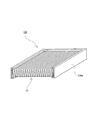
- FIG. 3 is a cross-sectional perspective view showing a filter unit formed using the filter pleat pack according to the embodiment of the present invention.
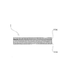
- the filter medium 1 is formed in a sheet shape as shown in FIG.
- the filter medium 1 is formed by stacking a plurality of sheet-shaped filter mediums. Specifically, the filter medium 1 is formed by laminating the first filter medium layer 2 having air permeability and the second filter medium layer 3 having air permeability. The first filter medium layer 2 forms one surface of the filter medium 1 and the second filter medium layer 3 forms the other surface of the filter medium 1.
- the first filter medium layer 2 is composed of a porous film (hereinafter also referred to as a fluororesin porous film) 2a mainly composed of a fluororesin.
- the fluororesin porous film 2a is mainly made of fluororesin, and has a fibril portion (fibrous portion) and a node portion (nodule portion) connected to the fibril portion.
- "mainly” means that it is contained in an amount of more than 50 mass% with respect to the entire components of the first filter medium layer 2.
- the first filter medium layer 2 may contain less than 50% by weight of a component different from the fluororesin.
- Examples of the component different from the fluororesin include an inorganic filler which is a non-melt-processable component that does not become fibrous.
- Examples of the fluororesin forming the fluororesin porous membrane 2a include polytetrafluoroethylene (PTFE), fluorinated ethylene propylene, perfluoroalkoxy polymer, poly(ethylene-co-tetrafluoroethylene-co-hexafluoropropylene) ( EFEP), tetrafluoroethylene hexafluoropropylene vinylidene fluoride (THV), poly(tetrafluoroethylene-co-hexafluoropropylene) (FEP), perfluoroalkoxy (PFA), ethylene tetrafluoroethylene (ETFE) At least one of them is mentioned.
- PTFE polytetrafluoroethylene
- EFEP fluorinated ethylene propylene
- perfluoroalkoxy polymer poly(ethylene-co-
- the fluororesin porous membrane 2a is preferably a polytetrafluoroethylene porous membrane (hereinafter also referred to as PTFE porous membrane) formed by using polytetrafluoroethylene (PTFE) as the fluororesin. ..
- PTFE polytetrafluoroethylene porous membrane
- Examples of PTFE constituting the PTFE porous membrane include those that can be made into fibers (specifically, those having a high molecular weight) as described below.
- the fluororesin porous film 2a may be formed by stacking a plurality of films made of the above fluororesins.
- the thickness of the first filter medium layer 2 that is, the fluororesin porous membrane 2a
- the thickness of the first filter medium layer 2 is not particularly limited, but may be, for example, 0.1 um or more and 100 um or less, preferably 1 um or more and 20 um or less. It may be.
- the method for forming the PTFE porous membrane is not particularly limited, and for example, the following method can be adopted. Specifically, a liquid lubricant is added to PTFE fine powder to form a paste-like mixture.
- the liquid lubricant is not particularly limited as long as it can impart appropriate wettability to the surface of the mixture, and it is preferable that it can be removed by extraction treatment or heat treatment.
- liquid paraffin, naphtha, hydrocarbon such as white oil, and the like can be used as the liquid lubricant.
- the mixture is preformed into a rod-like shape under a pressure such that the liquid lubricant is not separated from the obtained paste-like mixture.
- the obtained rod-shaped preform is extruded or rolled to form a strip.
- the obtained strip-shaped molded product is stretched in the longitudinal direction and the width direction.
- the band-shaped molded article is made porous (fibrous) to form a PTFE porous membrane.
- the second filter medium layer 3 is made of a breathable filter medium (hereinafter, also referred to as a second filter medium layer breathable filter medium) 3a.
- the thickness of the second filter medium layer 3 (that is, the second filter medium layer air-permeable filter medium 3a) is not particularly limited, and is preferably 100 ⁇ m or more and 1000 ⁇ m or less, for example.
- the air permeability (air permeability) of the second filter material layer air-permeable filter material 3a is not particularly limited, and is preferably 10 cm 3 /cm 2 /s or more, for example.
- the member forming the second filter medium layer air-permeable filter medium 3a is not particularly limited, and is preferably made of, for example, a substance having a melting point of 127°C or higher.
- the second filter material layer breathable filter material 3a is not particularly limited, and may be formed of, for example, a plurality of fibrous members (for example, woven cloth, non-woven cloth, felt, etc.), or formed of mesh members. At least one of those (for example, mesh, net, etc.) and those formed from a foam-like member (for example, sheet-shaped sponge) can be used. In particular, it is preferable to use a non-woven fabric as the second filter medium layer air-permeable filter medium 3a.
- the basis weight of the nonwoven fabric is not particularly limited and may be, for example, 15 g/m 2 or more, 20 g/m 2 or more, and 30 g/m 2 or more, It may be 700 g/m 2 or less, 300 g/m 2 or less, 100 g/m 2 or less, or 70 g/m 2 or less. With such a basis weight, it is possible to prevent the non-woven fabric (that is, the second filter medium layer breathable filter medium 3a) from being excessively softened when performing thermal lamination described later. Further, the diameter of the fibers forming the non-woven fabric is not particularly limited, and is preferably 5 ⁇ m or more and 100 ⁇ m or less, for example.
- non-bonded substance having no hydrolyzable chemical bond (specifically, ester bond and/or amide bond, etc.).
- hydrolyzed substance a substance having no hydrolyzable chemical bond (specifically, ester bond and/or amide bond, etc.).
- non-hydrolyzable substances examples include polypropylene (PP), polymethylpentene (PMP), polyphenylene sulfide (PPS), polytetrafluoroethylene (PTFE), polyether ketone, polyether ether ketone, polyether sulfone, polyphenylene ether, At least one selected from the group consisting of polysulfone and polymethylpentene can be mentioned.
- each fiber that is a member constituting the nonwoven fabric is formed of an unhydrolyzed substance. More specifically, the entire fibers, which are members constituting the non-woven fabric, may be formed of the non-hydrolyzable substance.
- each fiber that is a member constituting the non-woven fabric has a sheath portion formed in a tubular shape and a core portion that fills the inside of the sheath portion (when the fiber has a so-called core-sheath structure)
- the sheath may be formed of a non-hydrolyzable substance.
- the core portion is made of an unhydrolyzed substance or a substance other than the unhydrolyzed substance (specifically, a hydrolyzable substance having an ester bond and/or an amide bond, etc.). It may be formed.
- the core portion and the sheath portion are preferably composed of substances having different melting points. Examples of the substance other than the non-hydrolyzable substance forming the core include at least one selected from the group consisting of polyethylene terephthalate (PET), nylon, polylactic acid, and polyimide.
- the filter medium 1 is formed only by the first filter medium layer 2 (that is, the fluororesin porous membrane 2a) and the second filter medium layer 3 (that is, the second filter medium layer breathable filter medium 3a). .. Further, the first filter medium layer 2 (that is, the fluororesin porous membrane 2a) and the second filter medium layer 3 (that is, the second filter medium layer breathable filter medium 3a) are laminated so as to be in contact with each other. Then, the first filter medium layer 2 (that is, the fluororesin porous membrane 2a) and the second filter medium layer 3 (that is, the second filter medium layer breathable filter medium 3a) are directly adhered to each other, whereby the filter medium 1 is formed. ..
- the method for directly adhering the fluororesin porous membrane 2a and the second filter medium layer breathable filter medium 3a is not particularly limited, and for example, a method of heat lamination (heat welding) can be adopted.
- a method of heat lamination heat welding
- the method for thermally laminating the fluororesin porous membrane 2a and the second filter medium layer air-permeable filter medium 3a is not particularly limited, and for example, a fluororesin porous film may be provided between a pair of roller members (not shown).
- the porous membrane 2a and the second filter medium layer breathable filter medium 3a (specifically, nonwoven fabric) are conveyed while laminating the porous membrane 2a and the second filter medium layer breathable filter medium 3a (specifically, nonwoven fabric). It is possible to employ a method in which (1) and (3) are continuously thermocompression bonded.
- the portion of the second filter medium layer air-permeable filter medium 3a (specifically, a nonwoven fabric) that is in contact with the fluororesin porous membrane 2a is softened by heat, so that the fluororesin porous membrane 2a The state in which the second filter medium layer and the air-permeable filter medium 3a are stuck together is maintained.
- the thickness of the filter medium 1 formed as described above is not particularly limited and may be, for example, 0.01 mm or more and 2 mm or less, and preferably 0.1 mm or more and 1.0 mm or less. May be.
- the air permeability of the filter medium 1 is not particularly limited, and may be, for example, 1 cm 3 /cm 2 /s or more and 50 cm 3 /cm 2 /s or less, preferably 1 cm 3 /cm 2. / s or 10 cm 3 / cm 2 / s may be less.
- the pressure loss of the filter medium 1 is not particularly limited and may be, for example, 350 Pa or less, preferably 250 Pa or less.
- the collection efficiency of the filter medium 1 is not particularly limited, and may be, for example, 90% or more, preferably 95% or more, and more preferably 97% or more. May be.
- the PF value of the filter medium 1 is not particularly limited, and may be, for example, 5 or more, preferably 10 or more.
- the PF value is a numerical value that is an index of the collection performance of the filter medium 1, and the larger the value, the higher the collection performance.
- the above pressure loss is based on the method specified in JIS K0901. The outline of such a method will be described.
- the filter medium 1 is set so as to close the opening of an annular holder (having a circular opening and an opening area of 100 cm 2 ).
- air is allowed to permeate only into the region of the filter medium 1 located inside the holder.
- a pressure difference is generated between the one surface side and the other surface side of the filter medium 1.
- the linear flow velocity of the air passing through the filter medium 1 is measured with a flow meter, and the pressure difference when the linear flow velocity reaches 5.3 cm/sec is measured with a pressure gauge (manometer).
- the pressure difference is measured 8 times, and the average value thereof is used as the pressure loss of the filter medium 1.
- the above collection efficiency is based on the following method. Specifically, the filter medium 1 is set so as to close the opening of an annular holder (having a circular opening and an opening area of 100 cm 2 ). Next, air is allowed to permeate only into the region of the filter medium 1 located inside the holder. This causes a pressure difference between one surface side and the other surface side of the filter medium 1. Then, the linear flow velocity of the air passing through the filter medium 1 is measured by a flow meter, and the air amount is adjusted so that the linear flow velocity becomes 5.3 cm/sec.
- the content (upstream particle concentration) of monodisperse bis(2-ethylhexyl) sebacate (DEHS) particles having a particle diameter of 0.15 ⁇ m was measured by using a monodisperse measuring device.
- the particles are supplied to air so that the particles are permeated through the filter medium so that the number of particles becomes about 10 7 particles/L.
- the concentration of the monodisperse DEHS particles on the downstream side is measured with a particle counter through the filter medium 1, and the collection efficiency (%) can be obtained by the following formula (1).
- the above PF value is based on the following method. Specifically, it is obtained based on the above collection efficiency (CE) and pressure loss (PL), and the following equation (2).
- the unit of the pressure loss PL in the equation (2) is mmH 2 O.
- the filter medium 1 configured as described above may be used in a flat shape or may be used in a state of being folded back in a pleated shape (folded shape) (so-called pleated state). Below, what the filter medium 1 was pleated is also called a filter pleat pack.
- the method for pleating the filter medium 1 is not particularly limited, and, for example, a known method using a reciprocating type processing machine or a rotary type processing machine can be used. Specifically, the filter medium 1 is continuously folded back along a mountain fold line and a valley fold line that are alternately set in the longitudinal direction of the elongated filter medium 1 and are set parallel to the width direction. Can be used for pleating.
- the filter medium 1 as a filter pleat pack, it is possible to increase the filtration area with respect to the ventilation area (opening area of the frame) of the filter unit when incorporated in a filter unit described later.
- the filter pleat pack formed as described above includes, for example, the filter pleat pack 10 shown in FIG.
- the filter pleat pack 10 includes a flat plate-shaped region (hereinafter also referred to as a flat plate portion) 10a arranged in the filter medium 1 so as to face each other, and a gap holding portion that holds a gap between adjacent flat plate portions 10a, 10a. 10b.
- the space holding portion 10b is linearly formed on one surface side and the other surface side of the filter medium 1.
- the spacing member 10b is formed of an adhesive (for example, hot melt) linearly applied to one surface of the filter medium 1 and the other surface thereof.
- the space holding portion 10b is formed so as to extend in a direction intersecting with a bent portion (hereinafter, also referred to as a bent portion) 10c of the filter medium 1. Moreover, it is preferable that the space holding portion 10b is formed so as to be in contact with the second filter medium layer 3. In other words, it is preferable that the spacing member 10b is formed by applying an adhesive to the second filter medium layer 3 (that is, so as not to contact the fluororesin porous membrane 2a). In addition, it is preferable that a plurality of space holding portions 10b be formed at intervals in the extending direction of the bent portion 10c.
- the adhesive forming the space holding portion 10b is not particularly limited, and a resin such as polyamide or polyolefin can be melted and used.
- the filter pleat pack 10 configured as described above constitutes the filter unit 100 by being supported by the frame body 100a as shown in FIG.
- the frame body 100 a is configured to support the outer peripheral end portion of the filter pleat pack 10. That is, the region inside the outer peripheral end of the filter pleat pack 10 is exposed to the opening of the frame body 100a.
- the material forming the frame body 100a is not particularly limited, and for example, a metal material, a resin material, or a composite material thereof can be used.
- the filter pleat pack 10 may be supported by the frame body 100a at the same time when the frame body 100a is molded.
- the use of the filter medium 1, the filter pleat pack 10 and the filter unit 100 configured as described above is not particularly limited, and for example, a mask for preventing dust from entering, bacteria and/or viruses can be used. It can be used as a mask for preventing invasion, a mask for preventing invasion of chemical substances and radioactive substances, and can also be used for applications other than masks (for example, bag filters).
- a mask using the filter medium 1 for example, a mask that meets the N95 standard of the National Institute of Occupational Safety and Health (NIOSH) (the collection efficiency of predetermined NaCl particles is 95% or more) and JIS Z 8122 are specified. HEPA filter and the like.
- the filter medium 1, the filter pleat pack 10, and the filter unit 100 configured as described above may be heated in steam for the purpose of sterilization and the like.
- the temperature for heating is not particularly limited, and is preferably 90° C. or higher and 140° C. or lower, and more preferably 120° C. or higher and 135° C. or lower.
- the humidity at the time of heating is not particularly limited, and may be, for example, the amount of saturated steam at the heating temperature.
- the heating time is not particularly limited, and is preferably 4 minutes or more and 35 minutes or less, for example.
- the filter medium 1 has a relatively low strength decrease due to being heated in the steam as described above.
- the ratio of the tensile strength after being heated in steam to the tensile strength before being heated in steam is 15% or less. It is preferably 10% or less, more preferably 8% or less, still more preferably 6% or less.
- the filter medium according to the first embodiment it is possible to suppress a decrease in strength caused by being heated in steam.
- the first filter medium layer 2 forms one surface of the filter medium 1 and the second filter medium layer 3 forms the other surface of the filter medium 1.
- the first filter medium layer 2 is made of a fluororesin porous membrane 2a mainly made of fluororesin
- the second filter medium layer 3 is made of a breathable filter medium 3a.
- at least the surface of the member constituting the breathable filter medium 3a is formed of at least one non-hydrolyzable substance selected from the group consisting of the above substances.
- the second filter medium layer 3 is less likely to be hydrolyzed, so that it is possible to suppress a decrease in strength when the filter medium 1 is heated in steam.
- the breathable filter medium 3a is made of a non-woven fabric. Then, each fiber, which is a member constituting the nonwoven fabric, may be entirely formed of an unhydrolyzed substance. In such a case, the strength reduction when the filter medium 1 is heated in steam can be suppressed more effectively.
- each fiber which is a member constituting the nonwoven fabric, may include a sheath portion and a core portion, and the sheath portion may be formed of an inhydrolyzable substance.
- the strength reduction when the filter medium 1 is heated in steam can be suppressed more effectively.
- the filter medium 1 may be composed of only the first filter medium layer 2 and the second filter medium layer 3, and the first filter medium layer 2 and the second filter medium layer 3 may be directly bonded.
- the rigidity of the first filter medium layer 2 can be supplemented by the second filter medium layer 3 and deterioration of the components other than the first filter medium layer 2 and the second filter medium layer 3 can be prevented.
- the filter medium 1 having good rigidity and air permeability can be obtained, and the first filter medium layer 2 and the second filter medium can be obtained. Good adhesion with the layer 3 can be obtained.
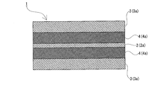
- the filter medium 1 according to the second embodiment of the present invention will be described with reference to FIG.
- the filter medium 1 according to the second embodiment is different from the filter medium 1 according to the first embodiment in that two filter medium layers 3 are provided. Therefore, the points different from the filter medium 1 of the first embodiment will be described below.
- the filter medium 1 includes a first filter medium layer 2 (that is, a fluororesin porous membrane 2a) and two second filter medium layers 3 and 3 (that is, second filter medium layers breathable filter mediums 3a and 3a). And are laminated to form a sheet. Then, one surface of the filter medium 1 is formed by one of the two second filter medium layers 3 and 3, and the other surface of the filter medium 1 is formed by the other of the two second filter medium layers 3 and 3. That is, in the present embodiment, the first filter medium layer 2 (that is, the fluororesin porous membrane 2a) is laminated between the two second filter medium layers 3 and 3 (that is, the second filter medium layer breathable filter mediums 3a and 3a). Thus, the filter medium 1 is formed.
- a first filter medium layer 2 that is, a fluororesin porous membrane 2a
- two second filter medium layers 3 and 3 that is, second filter medium layers breathable filter mediums 3a and 3a
- the filter medium 1 includes a first filter medium layer 2 (that is, a fluororesin porous membrane 2a) and two second filter medium layers 3 and 3 (that is, second filter medium layers breathable filter mediums 3a and 3a). ) Only. Further, the first filter medium layer 2 (that is, the fluororesin porous membrane 2a) and each second filter medium layer 3 (that is, each second filter medium layer breathable filter medium 3a) are laminated so as to be in contact with each other. Then, the first filter medium layer 2 (that is, the fluororesin porous membrane 2a) and each second filter medium layer 3 (that is, each second filter medium layer breathable filter medium 3a) are directly adhered to each other to form the filter medium 1 To be done.
- the method for directly adhering the fluororesin porous membrane 2a and the second filter medium layer breathable filter medium 3a is not particularly limited, and for example, a method of heat lamination (heat welding) can be adopted.
- one surface of the filter medium 1 is formed by one of the two second filter medium layers 3 and 3, and the two second filter medium layers 3 and 3 are formed.
- the other surface of the filter medium 1 is formed by the other surface.
- the first filter medium layer 2 is formed of a fluororesin porous membrane 2a mainly composed of a fluororesin
- the two second filter medium layers 3 and 3 are formed of a breathable filter medium.
- At least the surface of the member forming the breathable filter medium is formed of at least one non-hydrolyzable substance selected from the group consisting of the above substances.
- the second filter medium layer 3 is less likely to be hydrolyzed on both sides of the filter medium 1, so that it is possible to suppress a decrease in strength when the filter medium 1 is heated in steam.
- the first filter medium layer 2 that is, the fluororesin porous membrane 2a
- the one filter medium layer 2 that is, the fluororesin porous membrane 2a
- the filter medium, the filter pleat pack, and the filter unit according to the present invention are not limited to the above embodiment, and various modifications can be made without departing from the gist of the present invention. Further, the configurations and methods of the plurality of embodiments described above may be arbitrarily adopted and combined (the configurations and methods according to one embodiment may be applied to the configurations and methods according to other embodiments. Of course, the configurations and methods according to the various modifications described below may be arbitrarily selected and used in the configurations and methods according to the above-described embodiments.
- the filter medium 1 is such that the first filter medium layer 2 (that is, the fluororesin porous membrane 2a) and the second filter medium layer 3 (that is, the second filter medium layer breathable filter medium 3a) are in contact with each other.
- the first filter medium layer 2 that is, the fluororesin porous membrane 2a
- the second filter medium layer 3 that is, the second filter medium layer breathable filter medium 3a
- breathability is provided between the first filter medium layer 2 and the second filter medium layer 3.
- It may be configured to include at least one third filter medium layer 4 having
- the third filter medium layer 4 having air permeability is laminated between the first filter medium layer 2 and the second filter medium layer 3, so that the first filter medium layer 2 and the second filter medium layer 3 with respect to the third filter medium layer 4. Since they can be adhered to each other, a filter medium having a structure of three layers or more can be easily manufactured.
- the third filter medium layer 4 is composed of a breathable filter medium (hereinafter, also referred to as a third filter medium layer breathable filter medium) 4a.
- the thickness of the third filter medium layer 4 (that is, the third filter medium layer breathable filter medium 4a) is not particularly limited, and is preferably 100 ⁇ m or more and 1000 ⁇ m or less, for example.
- the air permeability (air permeability) of the third filter medium layer breathable filter medium 4a is not particularly limited, and is preferably 10 cm 3 /cm 2 /s or more, for example.
- the third filter material layer breathable filter material 4a is not particularly limited, and may be formed of, for example, a plurality of fibrous members (for example, woven cloth, non-woven cloth, felt, etc.), or formed of a mesh member. At least one of those (for example, mesh, net, etc.) and those formed from a foam-like member (for example, sheet-shaped sponge) can be used. In particular, it is preferable to use a non-woven fabric as the breathable filter medium 4a of the third filter medium layer.
- the basis weight of the nonwoven fabric is not particularly limited and may be, for example, 15 g/m 2 or more, 20 g/m 2 or more, and 30 g/m 2 or more, It may be 700 g/m 2 or less, 300 g/m 2 or less, 100 g/m 2 or less, or 70 g/m 2 or less. With such a basis weight, it is possible to prevent the non-woven fabric (that is, the third filter medium layer breathable filter medium 4a) from being excessively softened when performing thermal lamination. Further, the diameter of the fibers forming the non-woven fabric is not particularly limited, and is preferably 5 ⁇ m or more and 100 ⁇ m or less, for example.
- each fiber which is a member constituting the nonwoven fabric, is formed of an unhydrolyzed substance or a substance other than the unhydrolyzed substance.
- the substance other than the non-hydrolyzed substance is not particularly limited, and examples thereof include at least one selected from the group consisting of polyethylene terephthalate, nylon, polylactic acid, and polyimide.
- first filter medium layer 2 that is, the fluororesin porous membrane 2a
- second filter medium layer 3 that is, the second filter medium layer breathable filter medium 3a
- third filter medium layer 4 that is, the third filter medium layer ventilation. You may comprise so that it may be heat-laminated with the characteristic filter medium 4a).
- each layer is configured to be heat-laminated, but is not limited to this, for example, by placing an adhesive or double-sided tape between each layer, each layer. It may be laminated.
- PTFE porous membrane manufactured by Nitto Denko
- PP fiber Product name: Eltas P03070 manufactured by Asahi Kasei
- PET fiber Unitika's product name: Marix 70500 WSO
- Nylon fiber Product name: Eltas N05040 manufactured by Asahi Kasei
- Nonwoven fabric 5 PPS fiber (Product name: PPS paper PS0080 manufactured by Hirose Paper Co., Ltd.)
- -Nonwoven fabric 6 core-sheath fiber having a core portion of PMP and a sheath portion of PP (manufactured by Japan Vilene, product name: OX19003)
- PTFE fiber Product name: Micropunch
- PTFE porous membrane was produced by the following method. Specifically, 20 parts by weight of a liquid lubricant (dodecane) is uniformly mixed with 100 parts by weight of PTFE fine powder ("Polyflon (registered trademark) PTFE F-104" manufactured by Daikin Co., Ltd., standard specific gravity: 2.162). A mixture was obtained. Next, the mixture was molded by paste extrusion to obtain a rod-shaped molded product. The obtained rod-shaped molded product was passed between a pair of metal rolling rolls to obtain a long sheet having a thickness of 200 ⁇ m. Then, the obtained long sheet was stretched in the longitudinal direction at a stretching temperature of 280° C. and then stretched in the width direction to prepare a PTFE porous membrane. Table 1 shows the stretching ratios in the longitudinal direction and the width direction.
- Filter Filter Material The above-mentioned materials to be used were laminated and heat-laminated so as to have the layer structure shown in Table 2 below to prepare filter filter materials of Examples and Comparative Examples.
- the filter medium of Example 6 has the first filter medium layer laminated between the two second filter medium layers.
- Table 1 below shows the PTFE porous membrane used in each example and each comparative example, and the conditions of thermal lamination.
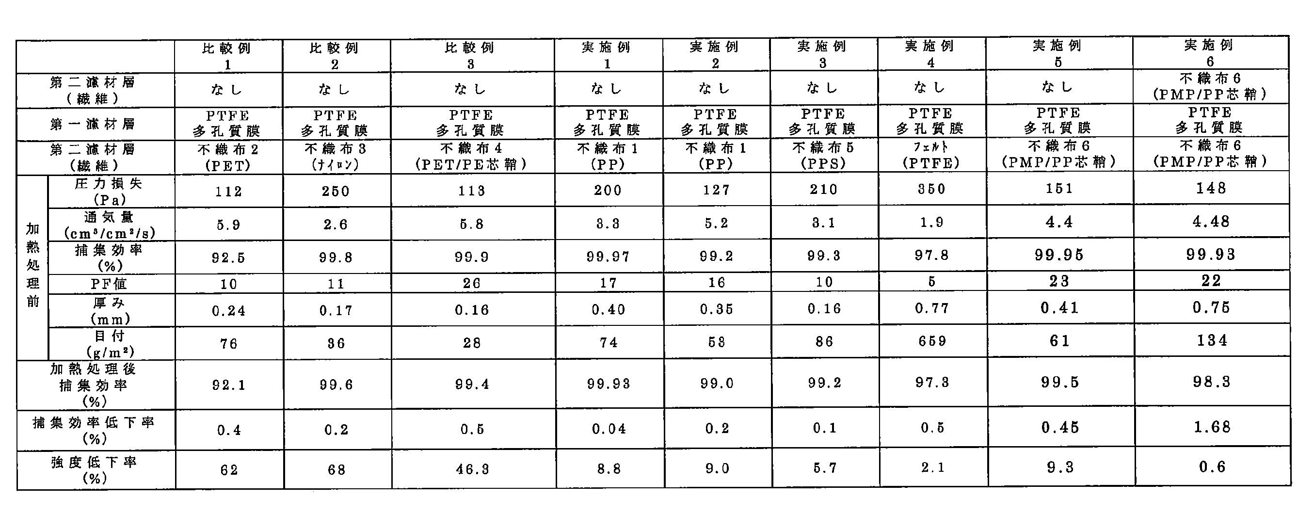
- Table 2 below shows the pressure loss, air flow rate, and collection efficiency of the filter medium.
- the strength before and after the heat treatment was measured.
- the strength was measured by the following method. Specifically, a rectangular test sample of 10 cm ⁇ 2.5 cm was cut out from each of the filter media 1 before and after the heat treatment. A tape having a width of 2 cm was applied to both ends in the longitudinal direction of the test sample, and the tape portion was set in a tensile tester (Tensilon RTC-1310A manufactured by Orientec Co., Ltd.). Then, a tensile strength test was performed at a tensile speed of 50 mm/min to measure the maximum stress (MPa). At this time, the distance between chucks in the tensile test was 6 cm. Then, the ratio of the maximum stress after the heat treatment to the maximum stress before the heat treatment was calculated as the strength reduction rate. The rate of decrease in strength is shown in Table 2 below.
- Examples 1 to 6 and Comparative Examples 1 to 3 in Table 2 are compared, it is recognized that Examples 1 to 6 have lower strength reduction rates. That is, since at least the surface of the member forming the breathable filter medium (that is, the second filter medium layer) is formed of the non-hydrolyzable substance, the second filter medium layer is formed even when the filter medium is heated in steam. Hard to hydrolyze. Therefore, it is possible to prevent the strength of the filter medium from being lowered due to heating in steam.
- Example 1 in the member that constitutes the air-permeable filter medium (that is, the second filter medium layer) with a substance having a melting point higher than the temperature at which the filter medium is heated in steam (hereinafter, also referred to as heating temperature). At least the surface is formed. Therefore, as in Comparative Example 3, at least the surface of the member forming the breathable filter medium (that is, the second filter medium layer) is formed of a substance having a lower melting point than the heating temperature (specifically, polyethylene in the sheath portion). As compared with the above case, the decrease in strength of the filter medium due to heating in steam can be suppressed.
- SYMBOLS 1 Filter filter medium, 2... 1st filter medium layer, 2a... Fluororesin porous membrane, 3... 2nd filter medium layer, 3a... 2 filter medium layer breathable filter medium, 4... 3rd filter medium layer, 4a... 3rd filter medium layer ventilation Filter material, 10... Filter pleat pack, 10a... Flat plate portion, 10b... Interval holding portion, 10c... Bending portion, 100... Filter unit, frame body... 100a
Landscapes
- Chemical & Material Sciences (AREA)
- Chemical Kinetics & Catalysis (AREA)
- Health & Medical Sciences (AREA)
- General Health & Medical Sciences (AREA)
- Physical Education & Sports Medicine (AREA)
- Engineering & Computer Science (AREA)
- Textile Engineering (AREA)
- Life Sciences & Earth Sciences (AREA)
- Zoology (AREA)
- Pulmonology (AREA)
- Business, Economics & Management (AREA)
- Emergency Management (AREA)
- Separation Using Semi-Permeable Membranes (AREA)
- Filtering Materials (AREA)
- Laminated Bodies (AREA)
Abstract
フィルタ濾材は、通気性を有する第一濾材層と通気性を有する第二濾材層とが積層されてシート状に形成されており、前記第一濾材層によって一方の面が形成され、前記第二濾材層によって他方の面が形成される。前記第一濾材層は、主としてフッ素樹脂から構成されたフッ素樹脂多孔質膜からなり、前記第二濾材層は、通気性濾材からなり、前記通気性濾材を構成する部材の少なくとも表面が不加水分解物質で形成されており、該不加水分解物質は、ポリプロピレン、ポリフェニレンサルファイド、ポリテトラフルオロエチレン、ポリエーテルケトン、ポリエーテルエーテルケトン、ポリエーテルサルホン、ポリフェニレンエーテル、ポリサルホン、及び、ポリメチルペンテンからなる群から選択される少なくとも一つである。
Description
本願は、日本国特願2018-247244号の優先権を主張し、引用によって本願明細書の記載に組み込まれる。
本発明は、フッ素樹脂多孔質膜を用いて形成されたフィルタ濾材、フィルタプリーツパック、フィルタユニットに関する。
従来から、気体に含まれる微粒子、菌類、ウイルス等を除去するために、主としてフッ素樹脂から構成された多孔質膜(以下、フッ素樹脂多孔質膜とも記す)を用いたフィルタ濾材が用いられている。斯かるフッ素樹脂多孔質膜は、厚みが比較的薄く、コシがないため、フッ素樹脂多孔質膜のみをフィルタ濾材として用いることが困難な場合もある。そこで、フッ素樹脂多孔質膜を第一濾材層とし、該第一濾材層に通気性を有する第二濾材層を積層したフィルタ濾材が提案されている(特許文献1,2参照)。
上記のようなフィルタ濾材の具体的な用途として、種々提案されているが、例えば、人の口や鼻を覆うマスクを構成する部材として用いられる場合がある。このようなマスクは、口鼻を覆うことにより、空気中の微粒子や菌類等が体内に取り込まれるのを防止するために使用されるものであるが、一つのマスクを繰り返し着用することで、マスクに付着した菌類等が増殖する虞がある。このように菌類等が増殖したマスクを着用すると、体内に菌類等が侵入し、感染症等を発症する要因となる。このため、一般的なマスクは、一度限りで使い捨てられる消耗品として扱われるのが通常である。
ところで、資源を有効利用する観点や、マスクを使用する環境等によっては、一つのマスクを繰り返し着用することが要求される場合がある。このような場合、使用済みのマスクを滅菌処理した後で着用することが必要となる。マスクを滅菌処理する方法としては、例えば、水蒸気中で加熱する方法(具体的には、オートクレーブ滅菌)が知られている。
しかしながら、このような水蒸気中での加熱によってフィルタ濾材の強度が著しく低下する虞がある。そして、このような水蒸気中での加熱による強度低下は、フィルタ濾材を使用した製品であれば、マスクに限らず生じ得る。
本発明は、上記のような問題に鑑み、水蒸気中で加熱されることによって強度が低下するのを抑制することができるフィルタ濾材を提供することを課題とする。
本発明の発明者らは、フィルタ濾材が水蒸気中で加熱された際に第二濾材層が加水分解することによって、フィルタ濾材の強度が著しく低下することを見出し、本発明を完成するに至った。
即ち、本発明に係るフィルタ濾材は、通気性を有する第一濾材層と通気性を有する第二濾材層とが積層されてシート状に形成されており、前記第一濾材層によって一方の面が形成され、前記第二濾材層によって他方の面が形成されており、前記第一濾材層は、主としてフッ素樹脂から構成されたフッ素樹脂多孔質膜からなり、前記第二濾材層は、通気性濾材からなり、前記通気性濾材を構成する部材の少なくとも表面が不加水分解物質で形成されており、該不加水分解物質は、ポリプロピレン、ポリフェニレンサルファイド、ポリテトラフルオロエチレン、ポリエーテルケトン、ポリエーテルエーテルケトン、ポリエーテルサルホン、ポリフェニレンエーテル、ポリサルホン、及び、ポリメチルペンテンからなる群から選択される少なくとも一つである。
また、本発明に係るフィルタ濾材は、通気性を有する第一濾材層と通気性を有する二つの第二濾材層とが積層されてシート状に形成されており、前記二つの第二濾材層の一方によって一方の面が形成され、前記二つの第二濾材層の他方によって他方の面が形成されており、前記第一濾材層は、主としてフッ素樹脂から構成されたフッ素樹脂多孔質膜からなり、前記二つの第二濾材層は、通気性濾材からなり、前記通気性濾材を構成する部材の少なくとも表面が不加水分解物質で形成されており、該不加水分解物質は、ポリプロピレン、ポリフェニレンサルファイド、ポリテトラフルオロエチレン、ポリエーテルケトン、ポリエーテルエーテルケトン、ポリエーテルサルホン、ポリフェニレンエーテル、ポリサルホン、及び、ポリメチルペンテンからなる群から選択される少なくとも一つである。
前記フッ素樹脂多孔質膜は、ポリテトラフルオロエチレン多孔質膜であることが好ましい。
前記通気性濾材は、不織布からなるものであり、該不織布を構成する部材である各繊維は、全体が不加水分解物質で形成されることが好ましい。
前記通気性濾材は、不織布からなるものであり、該不織布を構成する部材である各繊維は、筒状に形成された鞘部と該鞘部の内側を埋める芯部とを備えており、前記鞘部は、不加水分解物質で形成されることが好ましい。
また、本発明に係るフィルタ濾材は、第一濾材層及び第二濾材層のみからなり、第一濾材層と第二濾材層とが直接接着されてなることが好ましい。
また、本発明に係るフィルタ濾材は、通気性を有する第三濾材層が第一濾材層と第二濾材層との間に積層されることが好ましい。
第二濾材層を構成する不織布は、目付が15g/m2以上700g/m2以下であることが好ましい。
また、本発明に係るフィルタ濾材は、圧力損失が250Pa以下であってもよい。
また、本発明に係るフィルタ濾材は、捕集効率が95%以上であってもよい。
本発明に係るフィルタプリーツパックは、上記のフィルタ濾材がプリーツ状に折り返されて形成される。
本発明に係るフィルタユニットは、上記のフィルタプリーツパックと、該フィルタプリーツパックを支持する枠体とを備える。
<第一実施形態>
以下、本発明の第一実施形態について図1を参照しながら説明する。なお、以下の図面において同一または相当する部分には同一の参照符号を付しその説明は繰り返さない。
以下、本発明の第一実施形態について図1を参照しながら説明する。なお、以下の図面において同一または相当する部分には同一の参照符号を付しその説明は繰り返さない。
本実施形態に係るフィルタ濾材1は、図1に示すように、シート状に形成されるものである。また、フィルタ濾材1は、複数のシート状の濾材が積層されることで形成される。具体的には、フィルタ濾材1は、通気性を有する第一濾材層2と通気性を有する第二濾材層3とが積層されて形成される。そして、第一濾材層2は、フィルタ濾材1の一方の面を形成し、第二濾材層3は、フィルタ濾材1の他方の面を形成する。
第一濾材層2は、主としてフッ素樹脂から構成された多孔質膜(以下、フッ素樹脂多孔質膜とも記す)2aからなるものである。該フッ素樹脂多孔質膜2aは、主としてフッ素樹脂から構成され、フィブリル部(繊維状部)と、フィブリル部に接続されたノード部(結節部)とを有する。ここで、「主として」とは、第一濾材層2の構成成分全体に対して50質量%を超えて含有されることをいう。言い換えると、第一濾材層2は、フッ素樹脂と異なる成分を50重量%未満含有してもよい。フッ素樹脂と異なる成分としては、例えば、繊維化しない非溶融加工性成分である無機フィラー等が挙げられる。
フッ素樹脂多孔質膜2aを構成するフッ素樹脂としては、例えば、ポリテトラフルオロエチレン(PTFE)、フッ素化エチレンプロピレン、ペルフルオロアルコキシポリマー、ポリ(エチレン-コ-テトラフルオロエチレン-コ-ヘキサフルオロプロピレン)(EFEP)、テトラフルオロエチレンヘキサフルオロプロピレンビニリデンフルオリド(THV)、ポリ(テトラフルオロエチレン-コ-ヘキサフルオロプロピレン)(FEP)、ペルフルオロアルコキシ(PFA)、エチレンテトラフルオロエチレン(ETFE)からなる群より選択される少なくとも一つが挙げられる。特には、フッ素樹脂多孔質膜2aとしては、フッ素樹脂としてポリテトラフルオロエチレン(PTFE)を用いて形成されたポリテトラフルオロエチレン多孔質膜(以下、PTFE多孔質膜とも記す)であることが好ましい。PTFE多孔質膜を構成するPTFEは、後述するように繊維化し得るもの(具体的には、高分子量のもの)が挙げられる。なお、上記の各フッ素樹脂から構成される膜を複数重ねてフッ素樹脂多孔質膜2aが構成されてもよい。
第一濾材層2(即ち、フッ素樹脂多孔質膜2a)の厚みとしては、特に限定されるものではないが、例えば、0.1um以上100um以下であってもよく、好ましくは1um以上20um以下であってもよい。
フッ素樹脂多孔質膜2aを構成するフッ素樹脂としては、例えば、ポリテトラフルオロエチレン(PTFE)、フッ素化エチレンプロピレン、ペルフルオロアルコキシポリマー、ポリ(エチレン-コ-テトラフルオロエチレン-コ-ヘキサフルオロプロピレン)(EFEP)、テトラフルオロエチレンヘキサフルオロプロピレンビニリデンフルオリド(THV)、ポリ(テトラフルオロエチレン-コ-ヘキサフルオロプロピレン)(FEP)、ペルフルオロアルコキシ(PFA)、エチレンテトラフルオロエチレン(ETFE)からなる群より選択される少なくとも一つが挙げられる。特には、フッ素樹脂多孔質膜2aとしては、フッ素樹脂としてポリテトラフルオロエチレン(PTFE)を用いて形成されたポリテトラフルオロエチレン多孔質膜(以下、PTFE多孔質膜とも記す)であることが好ましい。PTFE多孔質膜を構成するPTFEは、後述するように繊維化し得るもの(具体的には、高分子量のもの)が挙げられる。なお、上記の各フッ素樹脂から構成される膜を複数重ねてフッ素樹脂多孔質膜2aが構成されてもよい。
第一濾材層2(即ち、フッ素樹脂多孔質膜2a)の厚みとしては、特に限定されるものではないが、例えば、0.1um以上100um以下であってもよく、好ましくは1um以上20um以下であってもよい。
フッ素樹脂多孔質膜2aがPTFE多孔質膜である場合、該PTFE多孔質膜を形成する方法としては、特に限定されるものではなく、例えば、以下の方法を採用することができる。具体的には、PTFEファインパウダーに液状潤滑剤を添加してペースト状の混合物を形成する。液状潤滑剤としては、混合物表面に適度な濡れ性を付与し得るものであれば、特に限定されるものではなく、抽出処理や加熱処理によって除去し得るものであれることが好ましい。例えば、流動パラフィン、ナフサ、ホワイトオイルなどの炭化水素等を液状潤滑剤として用いることができる。
そして、得られたペースト状の混合物から液状潤滑剤が分離しない程度の圧力で、前記混合物を棒状に予備成形する。次に、得られた棒状の予備成形物を押出成形や圧延成形することで帯状に成形する。その後、得られた帯状の成形物を長手方向と幅方向とに延伸する。これにより、帯状の成形物が多孔質化(繊維化)させてPTFE多孔質膜が形成される。
第二濾材層3は、通気性濾材(以下では、第二濾材層通気性濾材とも記す)3aからなるものである。第二濾材層3(即ち、第二濾材層通気性濾材3a)の厚みとしては、特に限定されるものではなく、例えば、100μm以上1000μm以下であることが好ましい。また、第二濾材層通気性濾材3aの通気性(通気量)としては、特に限定されるものではなく、例えば、10cm3/cm2/s以上であることが好ましい。また、第二濾材層通気性濾材3aを構成する部材は、特に限定されるものではなく、例えば、融点が127℃以上である物質で構成されることが好ましい。
第二濾材層通気性濾材3aとしては、特に限定されるものではなく、例えば、複数の繊維状の部材から形成されるもの(例えば、織布、不織布、フェルト等)、網状の部材から形成されるもの(例えば、メッシュ、ネット等)、及び、発泡体状の部材から形成されるもの(例えば、シート状のスポンジ等)の少なくとも一つを用いることができる。特には、第二濾材層通気性濾材3aとして不織布を用いることが好ましい。該不織布の目付としては、特に限定されるものではなく、例えば、15g/m2以上であってもよく、20g/m2以上であってもよく、30g/m2以上であってもよく、700g/m2以下であってもよく、300g/m2以下であってもよく、100g/m2以下であってもよく、70g/m2以下であってもよい。このような目付とすることで、後述の熱ラミネートを行う際に、不織布(即ち、第二濾材層通気性濾材3a)が軟化しすぎてしまうのを抑制することができる。また、不織布を構成する繊維の直径としては、特に限定されるものではなく、例えば、5μm以上100μm以下であることが好ましい。
また、第二濾材層通気性濾材3aを構成する部材の少なくとも表面は、加水分解する化学結合(具体的には、エステル結合、及び/又は、アミド結合等)を有さない物質(以下、不加水分解物質とも記す)で形成される。不加水分解物質としては、ポリプロピレン(PP)、ポリメチルペンテン(PMP)、ポリフェニレンサルファイド(PPS)、ポリテトラフルオロエチレン(PTFE)、ポリエーテルケトン、ポリエーテルエーテルケトン、ポリエーテルサルホン、ポリフェニレンエーテル、ポリサルホン、及び、ポリメチルペンテンからなる群から選択される少なくとも一つが挙げられる。
具体的には、第二濾材層通気性濾材3aとして不織布を用いる場合には、該不織布を構成する部材である各繊維の少なくとも表面が不加水分解物質で形成される。より詳しくは、不織布を構成する部材である各繊維の全体が不加水分解物質で形成されてもよい。又は、該不織布を構成する部材である各繊維が筒状に形成された鞘部と該鞘部の内側を埋める芯部とを備える場合(いわゆる芯鞘構造の繊維である場合)には、該鞘部が不加水分解物質で形成されてもよい。斯かる構成においては、芯部は、不加水分解物質、又は、不加水分解物質以外の物質(具体的には、エステル結合、及び/又は、アミド結合等を有する加水分解し得る物質等)で形成されてもよい。なお、芯部と鞘部とは、融点の異なる物質から構成されることが好ましい。芯部を構成する不加水分解物質以外の物質としては、ポリエチレンテレフタレート(PET)、ナイロン、ポリ乳酸、及び、ポリイミドからなる群から選択される少なくとも一つが挙げられる。
本実施形態では、フィルタ濾材1は、第一濾材層2(即ち、フッ素樹脂多孔質膜2a)、及び、第二濾材層3(即ち、第二濾材層通気性濾材3a)のみによって形成される。また、第一濾材層2(即ち、フッ素樹脂多孔質膜2a)と第二濾材層3(即ち、第二濾材層通気性濾材3a)とが接するように積層される。そして、第一濾材層2(即ち、フッ素樹脂多孔質膜2a)と第二濾材層3(即ち、第二濾材層通気性濾材3a)とが直接接着されることでフィルタ濾材1が形成される。フッ素樹脂多孔質膜2aと第二濾材層通気性濾材3aとを直接接着する方法としては、特に限定されるものではなく、例えば、熱ラミネート(熱溶着)する方法を採用することができる。この場合、第二濾材層通気性濾材3aを構成する部材の少なくとも表面は、第一濾材層2を構成するフッ素樹脂よりも融点の低い不加水分解物質で形成されることが好ましい。
フッ素樹脂多孔質膜2aと第二濾材層通気性濾材3aとを熱ラミネートする方法としては、特に限定されるものではなく、例えば、一対のローラー部材(図示せず)の間に、フッ素樹脂多孔質膜2aと第二濾材層通気性濾材3a(具体的には、不織布)とを積層しつつ搬送し、フッ素樹脂多孔質膜2aと第二濾材層通気性濾材3a(具体的には、不織布)とを連続的に加熱圧着する方法を採用することができる。このように形成されるフィルタ濾材1では、第二濾材層通気性濾材3a(具体的には、不織布)におけるフッ素樹脂多孔質膜2aと接する部分が熱によって軟化し、フッ素樹脂多孔質膜2aと第二濾材層通気性濾材3aとが貼合わされた状態が維持される。
上記のようにして形成されるフィルタ濾材1の厚みとしては、特に限定されるものではなく、例えば、0.01mm以上2mm以下であってもよく、好ましくは0.1mm以上1.0mm以下であってもよい。また、フィルタ濾材1の通気量としては、特に限定されるものではなく、例えば、1cm3/cm2/s以上50cm3/cm2/s以下であってもよく、好ましくは1cm3/cm2/s以上10cm3/cm2/s以下であってもよい。
また、フィルタ濾材1の圧力損失としては、特に限定されるものではなく、例えば、350Pa以下であってもよく、好ましくは250Pa以下であってもよい。また、フィルタ濾材1の捕集効率としては、特に限定されるものではなく、例えば、90%以上であってもよく、好ましくは95%以上であってもよく、さらに好ましくは97%以上であってもよい。また、フィルタ濾材1のPF値としては、特に限定されるものではなく、例えば、5以上であってもよく、好ましくは10以上であってもよい。なお、PF値は、フィルタ濾材1における捕集性能の指標となる数値であって、大きいほど捕集性能が高いことを意味するものである。
上記の圧力損失は、JIS K 0901に規定される方法に基づくものである。斯かる方法の概略を説明すると、環状のホルダー(円形の開口を有し開口面積が100cm2であるもの)の開口を塞ぐようにフィルタ濾材1をセットする。次に、該フィルタ濾材1におけるホルダーの内側に位置する領域のみに空気を透過させる。これにより、フィルタ濾材1の一方の面側と他方の面側との圧力差を発生させる。そして、フィルタ濾材1を透過する空気の線流速を流量計で測定し、該線流速が5.3cm/秒となったときの前記圧力差を圧力計(マノメータ)で測定する。そして、上記圧力差の測定を8回行い、その平均値をフィルタ濾材1の圧力損失とする。
また、上記の捕集効率は、以下の方法に基づくものである。具体的には、環状のホルダー(円形の開口を有し開口面積が100cm2であるもの)の開口を塞ぐようにフィルタ濾材1をセットする。次に、該フィルタ濾材1におけるホルダーの内側に位置する領域のみに空気を透過させる。これにより、フィルタ濾材1の一方の面側と他方の面側との圧力差を発生させる。そして、フィルタ濾材1を透過する空気の線流速を流量計で測定し、該線流速が5.3cm/秒となるように空気量を調節する。そして、斯かる状態で、単分散測定装置を用いた測定において粒径が0.15μmの単分散セバシン酸ビス(2-エチルへキシル)(DEHS)粒子の含有量(上流側の粒子濃度)が約107個/Lとなるように、該粒子を空気に供給してフィルタ濾材を透過させる。この際、フィルタ濾材1を介して下流側の単分散DEHS粒子の濃度をパーティクルカウンターで測定し、下記の(1)式により捕集効率(%)を得ることができる。

また、上記のPF値は、以下の方法に基づくものである。具体的には、上記の捕集効率(CE)及び圧力損失(PL)と、下記の式(2)に基づいて求められるものである。なお、(2)式における圧力損失PLの単位はmmH2Oである。

上記のように構成されるフィルタ濾材1は、平面状で使用されてもよく、プリーツ状(襞状)に折り返された状態(所謂、プリーツ加工された状態)で使用されてもよい。以下では、フィルタ濾材1がプリーツ加工されたものをフィルタプリーツパックともいう。
フィルタ濾材1をプリーツ加工する方法としては、特に限定されるものではなく、例えば、レシプロ式の加工機やロータリー式の加工機を用いた公知の方法を用いることができる。具体的には、長尺状のフィルタ濾材1の長手方向に向かって交互に設定され、且つ、幅方向平行に設定された山折り線および谷折り線で、フィルタ濾材1を連続して折り返すことでプリーツ加工を行うことができる。
フィルタ濾材1をフィルタプリーツパックとすることによって、後述するフィルタユニットに組み込んだ際に、当該フィルタユニットの通気面積(枠体の開口面積)に対する濾過面積を大きくすることができる。
上記のように形成されるフィルタプリーツパックとしては、例えば、図4に示すフィルタプリーツパック10が挙げられる。該フィルタプリーツパック10は、フィルタ濾材1における対向するように配置された平板状の領域(以下では、平板部とも記す)10aと、隣り合う平板部10a,10a同士の間隔を保持する間隔保持部10bとを備える。該間隔保持部10bは、フィルタ濾材1の一方の面側、及び、他方の面側に線状に形成される。また、間隔保持部10bは、フィルタ濾材1の一方の面、及び、他方の面に線状に塗布された接着剤(例えば、ホットメルト等)によって形成される。間隔保持部10bは、フィルタ濾材1の屈曲した部分(以下、屈曲部とも記す)10cと交差する方向に延びるように形成される。また、間隔保持部10bは、第二濾材層3と接するように形成されることが好ましい。換言すれば、間隔保持部10bは、接着剤が第二濾材層3に塗布されることで(即ち、フッ素樹脂多孔質膜2aと接しないように)形成されることが好ましい。また、間隔保持部10bは、屈曲部10cの延びる方向に、間隔を空けて複数形成されることが好ましい。なお、間隔保持部10bを形成する接着剤としては、特に限定されるものではなく、ポリアミド、又は、ポリオレフィン等の樹脂を溶融して用いることができる。
上記のように構成されるフィルタプリーツパック10は、図5に示すように、枠体100aに支持されることで、フィルタユニット100を構成する。枠体100aは、フィルタプリーツパック10の外周端部を支持するように構成される。つまり、フィルタプリーツパック10の外周端部よりも内側の領域が枠体100aの開口に露出するように構成される。枠体100aを構成する材料としては、特に限定されるものではなく、例えば、金属製のもの、樹脂製のもの、又は、これらを複合したものを用いることができる。なお、枠体100aが樹脂製の材料で形成される場合は、枠体100aの成形と同時にフィルタプリーツパック10が枠体100aに支持されるように構成してもよい。
上記のように構成されるフィルタ濾材1、フィルタプリーツパック10、及び、フィルタユニット100の用途としては、特に限定されるものではなく、例えば、粉塵の侵入を防止するマスク、細菌及び/又はウイルスの侵入を防止するマスク、化学物質や放射性物質の侵入を防止するマスク等に用いることができ、マスク以外の用途(例えば、バグフィルター等)で使用することもできる。フィルタ濾材1を用いたマスクとしては、例えば、米国労働安全衛生研究所(NIOSH)のN95規格(所定のNaCl粒子の捕集効率が95%以上)をクリアするものや、JIS Z 8122で規定されるHEPAフィルタ等が挙げられる。
また、上記のように構成されるフィルタ濾材1、フィルタプリーツパック10、及び、フィルタユニット100は、滅菌すること等を目的として、水蒸気中で加熱されてもよい。加熱する際の温度としては、特に限定されるものではなく、例えば、90℃以上140℃以下であることが好ましく、120℃以上135℃以下であることがより好ましい。また、加熱する際の湿度としては、特に限定されるものではなく、例えば、加熱温度における飽和水蒸気量であってもよい。また、加熱時間としては、特に限定されるものではなく、例えば、4分以上35分以下であることが好ましい。また、フィルタ濾材1は、上記のように水蒸気中で加熱されたことによる強度低下が比較的低くなるものである。具体的には、フィルタ濾材1は、水蒸気中で加熱される前の引っ張り強度に対する水蒸気中で加熱された後の引っ張り強度の割合(以下、強度低下率とも記す)が15%以下であることが好ましく、10%以下であることがより好ましく、8%以下であることが更に好ましく、6%以下であることが更に好ましい。
以上のように、第一実施形態に係るフィルタ濾材によれば、水蒸気中で加熱されることによって生じる強度の低下を抑制することができる。
即ち、第一濾材層2によってフィルタ濾材1の一方の面が形成され、第二濾材層3によってフィルタ濾材1の他方の面が形成される。また、第一濾材層2が主としてフッ素樹脂から構成されたフッ素樹脂多孔質膜2aからなり、第二濾材層3が通気性濾材3aからなる。そして、通気性濾材3aを構成する部材の少なくとも表面は、上記の各物質からなる群から選択される少なくとも一つの不加水分解物質で形成される。これにより、第二濾材層3が加水分解し難いため、フィルタ濾材1が水蒸気中で加熱された際の強度低下を抑制することができる。
また、通気性濾材3aは、不織布からなるものである。そして、該不織布を構成する部材である各繊維は、全体が不加水分解物質で形成されてもよい。斯かる場合には、フィルタ濾材1が水蒸気中で加熱された際の強度低下をより効果的に抑制することができる。
又は、不織布を構成する部材である各繊維が鞘部と芯部とを備え、該鞘部が不加水分解物質で形成されてもよい。斯かる場合には、フィルタ濾材1が水蒸気中で加熱された際の強度低下をより効果的に抑制することができる。
また、フィルタ濾材1が第一濾材層2及び第二濾材層3のみからなり、第一濾材層2と第二濾材層3とが直接接着されてもよい。斯かる場合には、第一濾材層2の剛性を第二濾材層3で補うことができると共に、第一濾材層2、第二濾材層3以外の劣化を防止することができる。
また、第二濾材層3を構成する不織布の目付が上記の範囲であることで、良好な剛性と通気性とを有するフィルタ濾材1を得ることができると共に、第一濾材層2と第二濾材層3との良好な接着性を得ることができる。
<第二実施形態>
次に、本発明の第二実施形態に係るフィルタ濾材1について、図2を参照しつつ説明する。第二実施形態に係るフィルタ濾材1は、第一実施形態のフィルタ濾材1と比較して、第二濾材層3を二つ備える点で異なるものである。従って、以下では、第一実施形態のフィルタ濾材1と異なる点について説明する。
次に、本発明の第二実施形態に係るフィルタ濾材1について、図2を参照しつつ説明する。第二実施形態に係るフィルタ濾材1は、第一実施形態のフィルタ濾材1と比較して、第二濾材層3を二つ備える点で異なるものである。従って、以下では、第一実施形態のフィルタ濾材1と異なる点について説明する。
第二実施形態に係るフィルタ濾材1は、第一濾材層2(即ち、フッ素樹脂多孔質膜2a)と二つの第二濾材層3,3(即ち、第二濾材層通気性濾材3a,3a)とが積層されてシート状に形成される。そして、二つの第二濾材層3,3の一方によってフィルタ濾材1の一方の面が形成され、二つの第二濾材層3,3の他方によってフィルタ濾材1の他方の面が形成される。つまり、本実施形態では、二つの第二濾材層3,3(即ち、第二濾材層通気性濾材3a,3a)の間に第一濾材層2(即ち、フッ素樹脂多孔質膜2a)が積層されてフィルタ濾材1が形成される。
本実施形態では、フィルタ濾材1は、第一濾材層2(即ち、フッ素樹脂多孔質膜2a)、及び、二つの第二濾材層3,3(即ち、第二濾材層通気性濾材3a,3a)のみによって形成される。また、第一濾材層2(即ち、フッ素樹脂多孔質膜2a)と各第二濾材層3(即ち、各第二濾材層通気性濾材3a)とが接するように積層される。そして、第一濾材層2(即ち、フッ素樹脂多孔質膜2a)と各第二濾材層3(即ち、各第二濾材層通気性濾材3a)とが直接接着されることでフィルタ濾材1が形成される。フッ素樹脂多孔質膜2aと第二濾材層通気性濾材3aとを直接接着する方法としては、特に限定されるものではなく、例えば、熱ラミネート(熱溶着)する方法を採用することができる。
以上のように、第二実施形態に係るフィルタ濾材1によれば、二つの第二濾材層3,3の一方によってフィルタ濾材1の一方の面が形成され、二つの第二濾材層3,3の他方によってフィルタ濾材1の他方の面が形成される。また、前記第一濾材層2が主としてフッ素樹脂から構成されたフッ素樹脂多孔質膜2aから形成され、二つの第二濾材層3,3が通気性濾材から形成される。そして、前記通気性濾材を構成する部材の少なくとも表面は、上記の各物質からなる群から選択される少なくとも一つである不加水分解物質で形成される。これにより、フィルタ濾材1の両面において第二濾材層3が加水分解し難いため、フィルタ濾材1が水蒸気中で加熱された際の強度低下を抑制することができる。また、第一濾材層2(即ち、フッ素樹脂多孔質膜2a)が二つの第二濾材層3,3(即ち、第二濾材層通気性濾材3a,3a)の間に配置されるため、第一濾材層2(即ち、フッ素樹脂多孔質膜2a)を両面側から保護することができる。
なお、本発明に係るフィルタ濾材、フィルタプリーツパック、及び、フィルタユニットは、上記実施形態に限定されるものではなく、本発明の要旨を逸脱しない範囲で種々の変更が可能である。また、上記した複数の実施形態の構成や方法等を任意に採用して組み合わせてもよく(1つの実施形態に係る構成や方法等を他の実施形態に係る構成や方法等に適用してもよく)、さらに、下記する各種の変更例に係る構成や方法等を任意に選択して、上記した実施形態に係る構成や方法等に採用してもよいことは勿論である。
例えば、上記実施形態では、フィルタ濾材1は、第一濾材層2(即ち、フッ素樹脂多孔質膜2a)と第二濾材層3(即ち、第二濾材層通気性濾材3a)とが接するように積層されて形成されているが、これに限定されるものではなく、例えば、図3(a)(b)に示すように、第一濾材層2と第二濾材層3との間に通気性を有する少なくとも一つの第三濾材層4を備えるように構成されてもよい。
通気性を有する第三濾材層4が第一濾材層2と第二濾材層3との間に積層されることで、第三濾材層4に対して第一濾材層2と第二濾材層3とを接着等することができるため、三層以上の構成を持つフィルタ濾材を容易に作製することができる。
第三濾材層4は、通気性濾材(以下、第三濾材層通気性濾材とも記す)4aからなるものである。第三濾材層4(即ち、第三濾材層通気性濾材4a)の厚みとしては、特に限定されるものではなく、例えば、100μm以上1000μm以下であることが好ましい。また、第三濾材層通気性濾材4aの通気性(通気量)としては、特に限定されるものではなく、例えば、10cm3/cm2/s以上であることが好ましい。
第三濾材層通気性濾材4aとしては、特に限定されるものではなく、例えば、複数の繊維状の部材から形成されるもの(例えば、織布、不織布、フェルト等)、網状の部材から形成されるもの(例えば、メッシュ、ネット等)、及び、発泡体状の部材から形成されるもの(例えば、シート状のスポンジ等)の少なくとも一つを用いることができる。特には、第三濾材層通気性濾材4aとして不織布を用いることが好ましい。該不織布の目付としては、特に限定されるものではなく、例えば、15g/m2以上であってもよく、20g/m2以上であってもよく、30g/m2以上であってもよく、700g/m2以下であってもよく、300g/m2以下であってもよく、100g/m2以下であってもよく、70g/m2以下であってもよい。このような目付とすることで、熱ラミネートを行う際に、不織布(即ち、第三濾材層通気性濾材4a)が軟化しすぎてしまうのを抑制することができる。また、不織布を構成する繊維の直径としては、特に限定されるものではなく、例えば、5μm以上100μm以下であることが好ましい。
第三濾材層通気性濾材4aとして不織布を使用する場合には、該不織布を構成する部材である各繊維は、少なくとも表面が不加水分解物質、又は、不加水分解物質以外の物質で形成されてもよい。不加水分解物質以外の物質としては、特に限定されるものではなく、例えば、ポリエチレンテレフタレート、ナイロン、ポリ乳酸、及び、ポリイミドからなる群から選択される少なくとも一つが挙げられる。
また、第一濾材層2(即ち、フッ素樹脂多孔質膜2a)及び第二濾材層3(即ち、第二濾材層通気性濾材3a)と、第三濾材層4(即ち、第三濾材層通気性濾材4a)とは、熱ラミネートされるように構成してもよい。
また、上記実施形態では、各層が熱ラミネートされるように構成されているが、これに限定されるものではなく、例えば、各層の間に接着剤や両面テープ等が配置されることで各層が貼合わされてもよい。
以下、本発明の実施例について説明する。
1.使用材料
・PTFE多孔質膜(日東電工社製)
・不織布1:PP繊維(旭化成社製 品名:エルタスP03070)
・不織布2:PET繊維(ユニチカ社製 品名:マリックス70500WSO)
・不織布3:ナイロン繊維(旭化成社製 品名:エルタスN05040)
・不織布4:芯部がPETで鞘部がPEの芯鞘繊維(ユニチカ社製 品名:エルベスS0303WDO)
・不織布5:PPS繊維(廣瀬製紙社製 品名:PPSペーパーPS0080)
・不織布6:芯部がPMPで鞘部がPPの芯鞘繊維(日本バイリーン製 品名:OX19003)
・フェルト:PTFE繊維(日本フェルト社製 品名:ミクロパンチFLF470/AW)
・PTFE多孔質膜(日東電工社製)
・不織布1:PP繊維(旭化成社製 品名:エルタスP03070)
・不織布2:PET繊維(ユニチカ社製 品名:マリックス70500WSO)
・不織布3:ナイロン繊維(旭化成社製 品名:エルタスN05040)
・不織布4:芯部がPETで鞘部がPEの芯鞘繊維(ユニチカ社製 品名:エルベスS0303WDO)
・不織布5:PPS繊維(廣瀬製紙社製 品名:PPSペーパーPS0080)
・不織布6:芯部がPMPで鞘部がPPの芯鞘繊維(日本バイリーン製 品名:OX19003)
・フェルト:PTFE繊維(日本フェルト社製 品名:ミクロパンチFLF470/AW)
2.PTFE多孔質膜の作製
上記のPTFE多孔質膜は、以下の方法で作製した。具体的には、PTFEファインパウダー(ダイキン社製「ポリフロン(登録商標)PTFE F-104」、標準比重:2.162)100重量部に液状潤滑剤(ドデカン)20重量部を均一に混合して混合物を得た。次に、該混合物をペースト押出しすることで成形し、ロッド状成形物を得た。得られたロッド状成形物を1対の金属圧延ロール間に通して、厚さ200μmの長尺シートを得た。そして、得られた長尺シートを280℃の延伸温度で長手方向に延伸した後、幅方向に延伸して、PTFE多孔質膜を作製した。長手方向及び幅方向の延伸倍率については表1に示す。
上記のPTFE多孔質膜は、以下の方法で作製した。具体的には、PTFEファインパウダー(ダイキン社製「ポリフロン(登録商標)PTFE F-104」、標準比重:2.162)100重量部に液状潤滑剤(ドデカン)20重量部を均一に混合して混合物を得た。次に、該混合物をペースト押出しすることで成形し、ロッド状成形物を得た。得られたロッド状成形物を1対の金属圧延ロール間に通して、厚さ200μmの長尺シートを得た。そして、得られた長尺シートを280℃の延伸温度で長手方向に延伸した後、幅方向に延伸して、PTFE多孔質膜を作製した。長手方向及び幅方向の延伸倍率については表1に示す。
3.フィルタ濾材の作製
下記表2に記載の層構成となるように、上記の各使用材料を積層して熱ラミネートし、各実施例及び各比較例のフィルタ濾材を作成した。なお、実施例6のフィルタ濾材は、二つの第二濾材層の間に第一濾材層が積層されたものである。また、各実施例及び各比較例で使用したPTFE多孔質膜、及び、熱ラミネートの条件については、下記表1に示す。また、フィルタ濾材の圧力損失、通気量、及び、捕集効率については、下記表2に示す。
下記表2に記載の層構成となるように、上記の各使用材料を積層して熱ラミネートし、各実施例及び各比較例のフィルタ濾材を作成した。なお、実施例6のフィルタ濾材は、二つの第二濾材層の間に第一濾材層が積層されたものである。また、各実施例及び各比較例で使用したPTFE多孔質膜、及び、熱ラミネートの条件については、下記表1に示す。また、フィルタ濾材の圧力損失、通気量、及び、捕集効率については、下記表2に示す。
4.加熱処理
各実施例及び各比較例のフィルタ濾材(サイズ:50cm×100cm)をオートクレーブ滅菌した。具体的には、飽和水蒸気中127℃で24時間、オートクレーブ滅菌を行った。
各実施例及び各比較例のフィルタ濾材(サイズ:50cm×100cm)をオートクレーブ滅菌した。具体的には、飽和水蒸気中127℃で24時間、オートクレーブ滅菌を行った。
5.強度の評価
各実施例及び各比較例のフィルタ濾材に対して、加熱処理の前後の強度を測定した。強度の測定は、以下の方法で行った。具体的には、加熱処理の前後それぞれのフィルタ濾材1から10cm×2.5cmの長方形状の試験サンプルを切り出した。該試験サンプルの長手方向の両端部に幅2cmのテープを張り、該テープ部分を引っ張り試験機(オリエンテック社製 テンシロン RTC-1310A)にセットした。そして、引っ張り速度50mm/分で引っ張り強度の試験を行い、最大応力(MPa)を測定した。このとき、引張試験のチャック間は6cmであった。そして、加熱処理前の最大応力に対する加熱処理後の最大応力の割合を強度低下率として算出した。強度低下率については、下記表2に示す。
各実施例及び各比較例のフィルタ濾材に対して、加熱処理の前後の強度を測定した。強度の測定は、以下の方法で行った。具体的には、加熱処理の前後それぞれのフィルタ濾材1から10cm×2.5cmの長方形状の試験サンプルを切り出した。該試験サンプルの長手方向の両端部に幅2cmのテープを張り、該テープ部分を引っ張り試験機(オリエンテック社製 テンシロン RTC-1310A)にセットした。そして、引っ張り速度50mm/分で引っ張り強度の試験を行い、最大応力(MPa)を測定した。このとき、引張試験のチャック間は6cmであった。そして、加熱処理前の最大応力に対する加熱処理後の最大応力の割合を強度低下率として算出した。強度低下率については、下記表2に示す。
6.捕集効率の評価
各実施例及び各比較例のフィルタ濾材に対して、加熱処理の前後の捕集効率を測定した。捕集効率は、上記実施形態に記載の方法に基づいて得られたものである。そして、加熱処理前の捕集効率に対する加熱処理後の捕集効率の割合(捕集効率低下率)を算出した。捕集効率低下率については、下記表2に示す。
各実施例及び各比較例のフィルタ濾材に対して、加熱処理の前後の捕集効率を測定した。捕集効率は、上記実施形態に記載の方法に基づいて得られたものである。そして、加熱処理前の捕集効率に対する加熱処理後の捕集効率の割合(捕集効率低下率)を算出した。捕集効率低下率については、下記表2に示す。

<まとめ>
表2の実施例1~6と比較例1~3とを比較すると、実施例1~6の方が強度低下率が低いことが認められる。つまり、通気性濾材(つまり、第二濾材層)を構成する部材の少なくとも表面が不加水分解物質で形成されることで、フィルタ濾材が水蒸気中で加熱された際にも、第二濾材層が加水分解し難い。このため、水蒸気中での加熱によるフィルタ濾材の強度の低下を抑制することができる。
また、実施例1~6では、フィルタ濾材が水蒸気中で加熱される温度(以下、加熱温度とも記す)よりも融点が高い物質で通気性濾材(つまり、第二濾材層)を構成する部材の少なくとも表面が形成される。このため、比較例3のように、加熱温度よりも融点が低い物質(具体的には、鞘部分のポリエチレン)で通気性濾材(つまり、第二濾材層)を構成する部材の少なくとも表面が形成される場合よりも、水蒸気中での加熱によるフィルタ濾材の強度の低下を抑制することができる。
表2の実施例1~6と比較例1~3とを比較すると、実施例1~6の方が強度低下率が低いことが認められる。つまり、通気性濾材(つまり、第二濾材層)を構成する部材の少なくとも表面が不加水分解物質で形成されることで、フィルタ濾材が水蒸気中で加熱された際にも、第二濾材層が加水分解し難い。このため、水蒸気中での加熱によるフィルタ濾材の強度の低下を抑制することができる。
また、実施例1~6では、フィルタ濾材が水蒸気中で加熱される温度(以下、加熱温度とも記す)よりも融点が高い物質で通気性濾材(つまり、第二濾材層)を構成する部材の少なくとも表面が形成される。このため、比較例3のように、加熱温度よりも融点が低い物質(具体的には、鞘部分のポリエチレン)で通気性濾材(つまり、第二濾材層)を構成する部材の少なくとも表面が形成される場合よりも、水蒸気中での加熱によるフィルタ濾材の強度の低下を抑制することができる。
1…フィルタ濾材、2…第一濾材層、2a…フッ素樹脂多孔質膜、3…第二濾材層、3a…二濾材層通気性濾材、4…第三濾材層、4a…第三濾材層通気性濾材、10…フィルタプリーツパック、10a…平板部、10b…間隔保持部、10c…屈曲部、100…フィルタユニット、枠体…100a
Claims (12)
- 通気性を有する第一濾材層と通気性を有する第二濾材層とが積層されてシート状に形成されており、
前記第一濾材層によって一方の面が形成され、前記第二濾材層によって他方の面が形成されており、
前記第一濾材層は、主としてフッ素樹脂から構成されたフッ素樹脂多孔質膜からなり、
前記第二濾材層は、通気性濾材からなり、
前記通気性濾材を構成する部材の少なくとも表面が不加水分解物質で形成されており、
該不加水分解物質は、ポリプロピレン、ポリフェニレンサルファイド、ポリテトラフルオロエチレン、ポリエーテルケトン、ポリエーテルエーテルケトン、ポリエーテルサルホン、ポリフェニレンエーテル、ポリサルホン、及び、ポリメチルペンテンからなる群から選択される少なくとも一つであるフィルタ濾材。 - 通気性を有する第一濾材層と通気性を有する二つの第二濾材層とが積層されてシート状に形成されており、
前記二つの第二濾材層の一方によって一方の面が形成され、前記二つの第二濾材層の他方によって他方の面が形成されており、
前記第一濾材層は、主としてフッ素樹脂から構成されたフッ素樹脂多孔質膜からなり、
前記二つの第二濾材層は、通気性濾材からなり、
前記通気性濾材を構成する部材の少なくとも表面が不加水分解物質で形成されており、
該不加水分解物質は、ポリプロピレン、ポリフェニレンサルファイド、ポリテトラフルオロエチレン、ポリエーテルケトン、ポリエーテルエーテルケトン、ポリエーテルサルホン、ポリフェニレンエーテル、ポリサルホン、及び、ポリメチルペンテンからなる群から選択される少なくとも一つであるフィルタ濾材。 - 前記フッ素樹脂多孔質膜は、ポリテトラフルオロエチレン多孔質膜である請求項1又は2に記載のフィルタ濾材。
- 前記通気性濾材は、不織布からなるものであり、
該不織布を構成する部材である各繊維は、全体が不加水分解物質で形成される請求項1乃至3の何れか一項に記載のフィルタ濾材。 - 前記通気性濾材は、不織布からなるものであり、
該不織布を構成する部材である各繊維は、筒状に形成された鞘部と該鞘部の内側を埋める芯部とを備えており、
前記鞘部は、不加水分解物質で形成される請求項1乃至3の何れか一項に記載のフィルタ濾材。 - 前記フィルタ濾材は、第一濾材層及び第二濾材層のみからなり、
第一濾材層と第二濾材層とが直接接着されてなる請求項1乃至5の何れか一項に記載のフィルタ濾材。 - 通気性を有する第三濾材層が第一濾材層と第二濾材層との間に積層される請求項1乃至6の何れか一項に記載のフィルタ濾材。
- 第二濾材層を構成する不織布は、目付が15g/m2以上700g/m2以下である請求項4乃至7の何れか一項に記載のフィルタ濾材。
- 圧力損失が250Pa以下である請求項1乃至8の何れか一項に記載のフィルタ濾材。
- 捕集効率が95%以上である請求項1乃至9の何れか一項に記載のフィルタ濾材。
- 請求項1乃至10の何れか一項に記載のフィルタ濾材がプリーツ状に折り返されて形成されるフィルタプリーツパック。
- 請求項11に記載のフィルタプリーツパックと、該フィルタプリーツパックを支持する枠体とを備えるフィルタユニット。
Applications Claiming Priority (2)
| Application Number | Priority Date | Filing Date | Title |
|---|---|---|---|
| JP2018247244 | 2018-12-28 | ||
| JP2018-247244 | 2018-12-28 |
Publications (1)
| Publication Number | Publication Date |
|---|---|
| WO2020137733A1 true WO2020137733A1 (ja) | 2020-07-02 |
Family
ID=71126188
Family Applications (1)
| Application Number | Title | Priority Date | Filing Date |
|---|---|---|---|
| PCT/JP2019/049565 Ceased WO2020137733A1 (ja) | 2018-12-28 | 2019-12-18 | フィルタ濾材、フィルタプリーツパック、フィルタユニット |
Country Status (2)
| Country | Link |
|---|---|
| JP (1) | JP2020108881A (ja) |
| WO (1) | WO2020137733A1 (ja) |
Cited By (3)
| Publication number | Priority date | Publication date | Assignee | Title |
|---|---|---|---|---|
| CN112680876A (zh) * | 2020-12-11 | 2021-04-20 | 厦门保瑞达环保科技有限公司 | 一种高精度塑化型丙纶毡的制作方法 |
| US20230347299A1 (en) * | 2020-08-27 | 2023-11-02 | W.L. Gore & Associates Inc. | Composite fluoropolymer membranes having different surface energies |
| CN117412799A (zh) * | 2021-06-04 | 2024-01-16 | 大金工业株式会社 | 空气过滤器滤材、褶裥状滤材、空气过滤器单元、口罩用滤材及空气过滤器滤材的再生方法 |
Citations (11)
| Publication number | Priority date | Publication date | Assignee | Title |
|---|---|---|---|---|
| JP2000033244A (ja) * | 1991-07-23 | 2000-02-02 | Daikin Ind Ltd | ラミネ―ト構造物 |
| JP2002370009A (ja) * | 2001-06-13 | 2002-12-24 | Nitto Denko Corp | タービン用吸気フィルタ濾材およびその使用方法 |
| JP2006142275A (ja) * | 2004-10-21 | 2006-06-08 | Matsushita Electric Ind Co Ltd | 酸素透過膜、酸素透過シート、およびこれらを含む電池 |
| JP2007075739A (ja) * | 2005-09-14 | 2007-03-29 | Nitto Denko Corp | フィルターユニットおよびフィルター濾材の使用方法 |
| CN103785298A (zh) * | 2012-11-01 | 2014-05-14 | 上海复正环保工程有限公司 | 复合半透滤膜 |
| JP2014188393A (ja) * | 2013-03-26 | 2014-10-06 | Fujifilm Corp | 酸性ガス分離用複合体、酸性ガス分離用モジュールおよび酸性ガス分離用モジュールの製造方法 |
| JP2015044189A (ja) * | 2013-07-30 | 2015-03-12 | 富士フイルム株式会社 | 酸性ガス分離用積層体および該積層体を備えた酸性ガス分離用モジュール |
| JP2018012071A (ja) * | 2016-07-21 | 2018-01-25 | 三菱ケミカル株式会社 | ガス透過膜及びその製造方法 |
| JP2018051546A (ja) * | 2016-09-30 | 2018-04-05 | 日東電工株式会社 | エアフィルタ濾材、エアフィルタパック及びエアフィルタユニット |
| JP3218892U (ja) * | 2017-09-08 | 2018-11-15 | 衛風科技股▲ふん▼有限公司Winresp Inc. | ナノ薄膜マスク |
| JP2018192441A (ja) * | 2017-05-19 | 2018-12-06 | Dic株式会社 | 気体分離膜、積層体、及びガス分離モジュール |
Family Cites Families (6)
| Publication number | Priority date | Publication date | Assignee | Title |
|---|---|---|---|---|
| JPH0622630B2 (ja) * | 1986-05-12 | 1994-03-30 | 株式会社クラレ | B型肝炎抗原除去用吸着剤 |
| JPH04354582A (ja) * | 1991-05-30 | 1992-12-08 | Sekisui Chem Co Ltd | 超純水輸送配管システム |
| JP2006061808A (ja) * | 2004-08-26 | 2006-03-09 | Nitto Denko Corp | マスク用通気フィルタ濾材 |
| JP2006136779A (ja) * | 2004-11-11 | 2006-06-01 | Toray Ind Inc | ラミネート型フィルター材およびその製造方法 |
| WO2007102427A1 (ja) * | 2006-03-02 | 2007-09-13 | Sei-Ichi Manabe | 孔拡散式平膜分離装置・平膜濃縮装置・孔拡散用再生セルロース多孔膜および非破壊式の平膜検査方法 |
| JP6115596B2 (ja) * | 2014-12-26 | 2017-04-19 | ダイキン工業株式会社 | エアフィルタ用濾材、フィルタパック、エアフィルタユニット、およびエアフィルタ用濾材の製造方法 |
-
2019
- 2019-12-13 JP JP2019225752A patent/JP2020108881A/ja active Pending
- 2019-12-18 WO PCT/JP2019/049565 patent/WO2020137733A1/ja not_active Ceased
Patent Citations (11)
| Publication number | Priority date | Publication date | Assignee | Title |
|---|---|---|---|---|
| JP2000033244A (ja) * | 1991-07-23 | 2000-02-02 | Daikin Ind Ltd | ラミネ―ト構造物 |
| JP2002370009A (ja) * | 2001-06-13 | 2002-12-24 | Nitto Denko Corp | タービン用吸気フィルタ濾材およびその使用方法 |
| JP2006142275A (ja) * | 2004-10-21 | 2006-06-08 | Matsushita Electric Ind Co Ltd | 酸素透過膜、酸素透過シート、およびこれらを含む電池 |
| JP2007075739A (ja) * | 2005-09-14 | 2007-03-29 | Nitto Denko Corp | フィルターユニットおよびフィルター濾材の使用方法 |
| CN103785298A (zh) * | 2012-11-01 | 2014-05-14 | 上海复正环保工程有限公司 | 复合半透滤膜 |
| JP2014188393A (ja) * | 2013-03-26 | 2014-10-06 | Fujifilm Corp | 酸性ガス分離用複合体、酸性ガス分離用モジュールおよび酸性ガス分離用モジュールの製造方法 |
| JP2015044189A (ja) * | 2013-07-30 | 2015-03-12 | 富士フイルム株式会社 | 酸性ガス分離用積層体および該積層体を備えた酸性ガス分離用モジュール |
| JP2018012071A (ja) * | 2016-07-21 | 2018-01-25 | 三菱ケミカル株式会社 | ガス透過膜及びその製造方法 |
| JP2018051546A (ja) * | 2016-09-30 | 2018-04-05 | 日東電工株式会社 | エアフィルタ濾材、エアフィルタパック及びエアフィルタユニット |
| JP2018192441A (ja) * | 2017-05-19 | 2018-12-06 | Dic株式会社 | 気体分離膜、積層体、及びガス分離モジュール |
| JP3218892U (ja) * | 2017-09-08 | 2018-11-15 | 衛風科技股▲ふん▼有限公司Winresp Inc. | ナノ薄膜マスク |
Cited By (6)
| Publication number | Priority date | Publication date | Assignee | Title |
|---|---|---|---|---|
| US20230347299A1 (en) * | 2020-08-27 | 2023-11-02 | W.L. Gore & Associates Inc. | Composite fluoropolymer membranes having different surface energies |
| CN112680876A (zh) * | 2020-12-11 | 2021-04-20 | 厦门保瑞达环保科技有限公司 | 一种高精度塑化型丙纶毡的制作方法 |
| CN112680876B (zh) * | 2020-12-11 | 2022-06-14 | 厦门保瑞达环保科技有限公司 | 一种高精度塑化型丙纶毡的制作方法 |
| CN117412799A (zh) * | 2021-06-04 | 2024-01-16 | 大金工业株式会社 | 空气过滤器滤材、褶裥状滤材、空气过滤器单元、口罩用滤材及空气过滤器滤材的再生方法 |
| EP4353344A4 (en) * | 2021-06-04 | 2024-08-21 | Daikin Industries, Ltd. | AIR FILTER MEDIA, PLEATED FILTER MEDIA, AIR FILTER UNIT, MASK FILTRATION MEDIA, AND METHOD FOR RECYCLING AIR FILTER MEDIA |
| US12533614B2 (en) | 2021-06-04 | 2026-01-27 | Daikin Industries, Ltd. | Air filter medium, pleated filter medium, air filter unit, mask filter medium, and method for regenerating air filter medium |
Also Published As
| Publication number | Publication date |
|---|---|
| JP2020108881A (ja) | 2020-07-16 |
Similar Documents
| Publication | Publication Date | Title |
|---|---|---|
| JP5608323B2 (ja) | フィルタ濾材とその製造方法ならびにフィルタユニット | |
| JP6933456B2 (ja) | エアフィルタ濾材、エアフィルタパック及びエアフィルタユニット | |
| JP6292920B2 (ja) | エアフィルタ濾材の製造方法、エアフィルタ濾材及びエアフィルタパック | |
| JP3362730B2 (ja) | エアフィルター濾材、それを用いたエアフィルターパック及びエアフィルターユニット並びにエアフィルター濾材の製造方法 | |
| JP5784458B2 (ja) | エアフィルタ濾材 | |
| CN111148561B9 (zh) | 空气过滤器滤材、过滤器褶裥组件及空气过滤器单元 | |
| WO2011158717A1 (ja) | 多孔膜を備える濾材、その製造方法、フィルタパック、ならびにフィルタユニット | |
| WO2020137733A1 (ja) | フィルタ濾材、フィルタプリーツパック、フィルタユニット | |
| KR20180002673A (ko) | 필터 여과재 및 필터 유닛 | |
| JP6185735B2 (ja) | フィルタ濾材の製造装置 | |
| JP2026027479A (ja) | フィルタプリーツパック及びエアフィルタユニット | |
| JP6043590B2 (ja) | フィルタ濾材およびフィルタユニット | |
| JP6209393B2 (ja) | フィルター濾材 | |
| JP2001170424A (ja) | エアフィルタ用ろ材およびそれを用いたエアフィルタユニット | |
| WO2013014828A1 (ja) | フィルタユニットおよびそれを備えた掃除機 | |
| JP2007160275A (ja) | フィルターユニットとその製造方法 | |
| JP2005246233A (ja) | 掃除機用エアフィルタ濾材およびそれを用いた掃除機用エアフィルタユニット | |
| TW201420167A (zh) | 過濾器濾材及過濾器濾材之製造裝置 | |
| JP7405837B2 (ja) | フィルタ濾材及びフィルタユニット | |
| WO2022065515A1 (ja) | エアフィルタ濾材、フィルタプリーツパック及びエアフィルタユニット | |
| JP4224437B2 (ja) | エアフィルタ濾材およびそれを用いたエアフィルタユニット | |
| JP2002011313A (ja) | エアフィルタ用ろ材およびこれを用いたエアフィルタユニット | |
| JP2002058974A (ja) | エアフィルター濾材、それを用いたエアフィルターパック及びエアフィルターユニット | |
| JP2025035415A (ja) | エアフィルタ濾材の製造方法、エアフィルタ濾材、フィルタパック、および、エアフィルタユニット | |
| CN121889201A (zh) | 空气过滤器滤材、空气过滤器滤材的使用方法以及空气处理装置 |
Legal Events
| Date | Code | Title | Description |
|---|---|---|---|
| 121 | Ep: the epo has been informed by wipo that ep was designated in this application |
Ref document number: 19905945 Country of ref document: EP Kind code of ref document: A1 |
|
| NENP | Non-entry into the national phase |
Ref country code: DE |
|
| 122 | Ep: pct application non-entry in european phase |
Ref document number: 19905945 Country of ref document: EP Kind code of ref document: A1 |