WO2020137598A1 - ごみ供給速度推定装置およびごみ供給速度推定方法 - Google Patents
ごみ供給速度推定装置およびごみ供給速度推定方法 Download PDFInfo
- Publication number
- WO2020137598A1 WO2020137598A1 PCT/JP2019/048851 JP2019048851W WO2020137598A1 WO 2020137598 A1 WO2020137598 A1 WO 2020137598A1 JP 2019048851 W JP2019048851 W JP 2019048851W WO 2020137598 A1 WO2020137598 A1 WO 2020137598A1
- Authority
- WO
- WIPO (PCT)
- Prior art keywords
- dust
- supply
- waste
- weight
- hopper
- Prior art date
- Legal status (The legal status is an assumption and is not a legal conclusion. Google has not performed a legal analysis and makes no representation as to the accuracy of the status listed.)
- Ceased
Links
Images



Classifications
-
- F—MECHANICAL ENGINEERING; LIGHTING; HEATING; WEAPONS; BLASTING
- F23—COMBUSTION APPARATUS; COMBUSTION PROCESSES
- F23G—CREMATION FURNACES; CONSUMING WASTE PRODUCTS BY COMBUSTION
- F23G5/00—Incineration of waste; Incinerator constructions; Details, accessories or control therefor
- F23G5/44—Details; Accessories
-
- F—MECHANICAL ENGINEERING; LIGHTING; HEATING; WEAPONS; BLASTING
- F23—COMBUSTION APPARATUS; COMBUSTION PROCESSES
- F23G—CREMATION FURNACES; CONSUMING WASTE PRODUCTS BY COMBUSTION
- F23G5/00—Incineration of waste; Incinerator constructions; Details, accessories or control therefor
- F23G5/50—Control or safety arrangements
-
- F—MECHANICAL ENGINEERING; LIGHTING; HEATING; WEAPONS; BLASTING
- F23—COMBUSTION APPARATUS; COMBUSTION PROCESSES
- F23G—CREMATION FURNACES; CONSUMING WASTE PRODUCTS BY COMBUSTION
- F23G5/00—Incineration of waste; Incinerator constructions; Details, accessories or control therefor
- F23G5/44—Details; Accessories
- F23G5/442—Waste feed arrangements
- F23G5/444—Waste feed arrangements for solid waste
-
- F—MECHANICAL ENGINEERING; LIGHTING; HEATING; WEAPONS; BLASTING
- F23—COMBUSTION APPARATUS; COMBUSTION PROCESSES
- F23G—CREMATION FURNACES; CONSUMING WASTE PRODUCTS BY COMBUSTION
- F23G7/00—Incinerators or other apparatus for consuming industrial waste, e.g. chemicals
Definitions
- the present invention in an incinerator for incinerating waste such as industrial waste, estimates a weight of refuse (hereinafter, referred to as "disposal rate") to be supplied into the incinerator per unit time. And a method for estimating a refuse supply rate.
- an incinerator that temporarily stores waste in a hopper and sequentially supplies the waste reaching the bottom of the hopper into an incinerator with a dust supply device.
- waste heat generated in the incinerator is recovered by the boiler.
- Patent Document 1 discloses an incineration facility equipped with a measuring device capable of measuring the amount of heat supplied to the dust supplied to the incinerator by a dust supply device.
- the scanning laser level meter installed above the hopper measures the height position of the dust surface inside the hopper, and based on the change in the measured height position of the dust surface, it is thrown into the hopper. Calculate the volume of waste (input waste volume) and the volume of waste supplied into the incinerator (waste moving volume) per unit time.
- the weight of the dust put in the hopper is detected by the weight scale attached to the crane that puts the dust in the hopper.
- the specific gravity of the dust thrown into the hopper is calculated from the detected dust weight and the thrown-in dust volume calculated. Furthermore, the heat supply amount of the refuse supplied to the incinerator per unit time is calculated from the calculated refuse specific gravity and the above-mentioned refuse moving volume supplied to the incinerator per unit time. The calculated amount of heat supplied to the dust is sent to the control device that controls the dust supply device. The control device controls the dust supply device so that the amount of supplied heat of dust per unit time is constant, using the received amount of supplied heat of dust as a control index.
- the dust supply device needs to be controlled so as to reach the planned incineration weight while monitoring the total weight of waste supplied to the furnace.
- the dust supply device is controlled so as to stabilize the combustion state in the incinerator, but it is considered to comply with a predetermined daily incineration weight plan for waste. Absent.
- the volume and specific gravity of the waste supplied into the incinerator are calculated. It is possible to monitor the total weight of waste supplied to the incinerator by adding up the weight of waste, which is the product of these values.
- the volume of these trash and the specific gravity of the trash are calculated from the level change of the trash in the hopper, the quantitative accuracy is poor in both cases, and the long-term (for example, 24 hours) obtained from these values
- the integrated value lacks accuracy. For this reason, a control index that satisfies both the predetermined daily incineration weight plan for refuse and the stabilization of the incineration state in the incinerator is desired.
- the present invention is capable of estimating a refuse supply rate that is a control index for achieving both compliance with a predetermined daily incineration weight plan for refuse and stabilization of the incineration state in the incinerator.
- An object of the present invention is to provide an apparatus and a waste supply rate estimation method.
- the waste supply speed estimation device includes an incinerator that incinerates waste, a hopper that stores waste that is input from above, a bucket that holds the waste, and the bucket.
- a crane that has a weight scale that measures the weight of the trash that has been caught, puts the trash in the pit into the hopper, a height measuring device that measures the surface height of the trash in the hopper, and the bottom of the hopper.
- the transition of the waste supply speed which is the weight per unit time of the waste supplied to the incinerator by the dust supply device, is estimated.
- a waste feed rate estimation device wherein a change in the weight of dust put into the hopper obtained from the measurement value of the scale is derived as a base component of the waste feed rate, and the height measurement is performed. From the change in the surface height measured by the device, while estimating the transition of the supply weight of the dust supplied to the incinerator by the dust supply device, the fluctuation of the estimated transition of the supply weight, the base A fluctuation component derivation unit that derives a fluctuation component of the refuse supply speed based on the component, and a supply speed estimation unit that estimates the transition of the garbage supply speed by superimposing the fluctuation component on the base component.
- the transition of the garbage supply rate is derived by dividing it into a base component and a variable component based on the base component, and estimating them by combining them.
- the base component is derived from the change in the weight of garbage measured by a scale.
- the waste that is put into the hopper by the crane is temporarily stored in the hopper and then supplied to the incinerator by the dust supply device. Therefore, from a long-term perspective, the weight of the waste put into the hopper by the crane can be regarded as the weight of the waste supplied to the incinerator by the dust supply device.
- the measurement value of the weighing scale is more accurate than the volume of the dust obtained from the measurement value of the height measuring device, and therefore the integrated value for a long time (for example, 24 hours) is also accurate. Therefore, the weight of the dust measured by the weight scale is suitable as a control index for adhering to a predetermined daily waste incineration weight plan.
- the fluctuation component is the fluctuation of the weight of refuse supplied to the furnace determined from the change in the surface height of the refuse inside the hopper measured by the height measuring device.
- the volume of dust obtained from the change in surface height measured by the height measuring device has poor quantitative accuracy.
- the change in the surface height measured by the height measuring device can catch the short-term fluctuation of the supplied weight of the dust supplied into the furnace, and the dust collector can be controlled according to this short-term fluctuation. By doing so, the stabilization of the incineration state in the incinerator can be improved.
- the incineration per unit time becomes a control index that makes it possible to both comply with the predetermined daily incineration weight plan for waste and stabilize the incineration state in the incinerator. It is possible to estimate the weight of refuse supplied to the furnace.
- the fluctuation component derivation unit was calculated based on the change in the surface height measured by the height measuring device immediately before and immediately after the dust is supplied into the incinerator by the dust supply device.
- the fluctuation component derivation unit extracts a fluctuation corresponding to the dust supply operation of the dust supply device from the estimated transition of the supplied weight, and the extracted fluctuation is the dust supply based on the base component. It may be derived as a velocity fluctuation component. According to this configuration, it is possible to reduce fluctuations other than fluctuations in accordance with the operation of the dust supply device, from changes in the dust supply speed estimated based on changes in the surface height measured by the height measuring device.
- the fluctuation component deriving unit performs a filtering process using a high-pass filter or a band-pass filter having a frequency characteristic according to the dust supply operation of the dust supply device, with respect to the transition of the supplied weight, and the filter.
- the processing result may be used as the fluctuation component of the refuse supply rate. According to this configuration, it is possible to easily extract a variation according to the operation of the dust supply device from the transition of the dust supply speed estimated based on the change in the surface height measured by the height measuring device.
- the supply speed estimation unit, the time axis of the base component and the time axis of the base component according to the residence time of the dust in the hopper from the time when the crane is thrown into the hopper until the bottom of the hopper.
- the time axis of the fluctuation component may be adjusted.
- the supply speed estimation unit performs a moving average process in a time width corresponding to the residence time on the transition of the dust weight measured by the weighing scale to obtain the base component.
- the time axis may be aligned with the time axis of the fluctuation component.
- the waste in the incinerator that sequentially supplies the dust thrown into the hopper into the incinerator by the dust supply device, the waste is supplied into the incinerator by the dust supply device.
- a method for estimating the rate of waste feed rate which is the weight of waste per unit time, which is a basis for deriving the transition of the weight of waste input to the hopper as a base component of the waste feed rate.
- the transition of the supply weight of the dust supplied into the incinerator by the dust supply device is estimated, and the estimated supply
- a supply rate estimation step is performed.
- the refuse supply rate estimation which can estimate the refuse supply rate used as a control index which makes it compatible with compliance with the predetermined daily refuse incineration weight plan and stabilization of the incineration state in an incinerator is demonstrated.
- An apparatus and a waste supply rate estimation method can be provided.
- FIG. 4B is a graph showing an example of the result of performing the filtering process on the temporal transition shown in FIG. 4A. It is a graph which shows an example of the time transition of the refuse supply speed estimated based on the time transition shown in FIG. 3 and the time transition shown in FIG. 4B. It is a flowchart which shows the flow of a dust supply speed estimation process.
- the incineration facility 100 includes a pit 10, a hopper 20, a dust supply device 30, an incinerator 40, a boiler 50, and a control device 60.
- the trash transported to the incinerator 100 is put into the pit 10 and stored.
- the pit 10 has a storage space 11 in which dust is stored, and a transport space 12 that is continuous with the storage space 11 above the transport space 12 and in which the dust stored in the storage space 11 is transported to the hopper 20.
- the transport space 12 of the pit 10 is provided with a crane 13 for loading the trash in the pit 10 into the hopper 20 at a predetermined loading interval.
- the crane 13 has a bucket 14 for grasping the dust in the pit 10, and conveys the dust grasped by the bucket 14 to above the hopper 20 and throws it into the hopper 20. Further, the crane 13 has a weight scale 15 that measures the weight of the dust that is gripped by the bucket 14 and is transported.
- a height measuring device 16 for measuring the height of the surface of the dust stored in the hopper 20 (hereinafter, also referred to as “dust height”) is provided in the transport space 12 of the pit 10.
- the height measuring device 16 is arranged in the transport space 12 of the pit 10.
- the height measuring device 16 is, for example, an ultrasonic level meter.
- the hopper 20 temporarily stores the dust thrown in from above by the crane 13 and sequentially supplies it downward. Every time the crane 13 loads the hopper 20, dust is stacked in the hopper 20. The height of the waste just after the waste is put into the hopper 20 is larger than that immediately before the waste is put into the hopper 20. On the other hand, the dust at the bottom of the hopper 20 is supplied into the incinerator 40 at any time by the dust supply device 30 provided at the bottom of the hopper 20. Therefore, the height of the dust immediately after the dust is supplied by the dust supply device 30 is smaller than that immediately before the dust is supplied by the dust supply device 30.
- the dust supply device 30 is provided in the lower part of the hopper 20, and supplies the dust thrown into the hopper 20 into the incinerator 40 at a time interval (feeding interval) shorter than the dust throwing interval into the hopper 20.
- the dust supply device 30 includes a pusher 31 that reciprocates in the horizontal direction and a drive device 32 that reciprocally drives the pusher 31.
- the drive device 32 is, for example, a hydraulic cylinder, and is arranged on the side of the hopper 20 opposite to the incinerator 40. However, the drive device 32 may not be arranged on the side of the hopper 20 opposite to the incinerator 40. For example, the drive device 32 may be arranged side by side with the pusher 31 when viewed from the incinerator 40 side.
- the pusher 31 has a substantially rectangular parallelepiped shape and is reciprocally driven by the bottom portion of the hopper 20. Then, the pusher 31 supplies the waste into the incinerator 40 by sequentially pushing out the waste inside the hopper 20 toward the inlet 40 a of the incinerator 40.
- the dust supply device 30 is controlled by the control device 60 described later.
- the incinerator 40 incinerates waste while transporting it.
- the incinerator 40 has a main combustion chamber 41 and a re-combustion chamber 42 continuous with the main combustion chamber 41 in order from the upstream side.
- the incinerator 40 is a stoker type incinerator, and below the main combustion chamber 41 and the re-combustion chamber 42 in the incinerator 40, in order from the upstream side, a drying stoker 43, a combustion stoker 43 as a means for transporting dust. 44 and a post-combustion stoker 45 are provided.
- Primary air is supplied to the main combustion chamber 41 through the stokers 43 to 45, and secondary air is supplied above the stokers 43 to 45.
- the main combustion chamber 41 is supplied with the exhaust gas discharged from the incinerator 40. Since the exhaust gas has an oxygen concentration lower than that of air, the exhaust gas is supplied to the main combustion chamber 41 in order to suppress a local excessive rise in the combustion temperature. In the present embodiment, part of the exhaust gas that has passed through the boiler 50 is returned to the main combustion chamber 41.
- the dust supplied into the incinerator 40 by the dust supply device 30 is first sent to the drying stoker 43 and dried by the radiant heat of the primary air and the main combustion chamber 41.
- the dust dried in the dry stoker 43 is sent to the combustion stoker 44 by the dry stoker 43 and burned, and a flame is generated.
- the dust in the combustion stoker 44 and the ash generated by the combustion are sent to the post-combustion stoker 45 by the combustion stoker 44.
- the post-combustion stoker 45 the unburned waste that could not be completely burned in the combustion stoker 44 is burned, and the ash after burning the waste is discharged from the chute 46 provided adjacent to the post-combustion stoker 45. ..
- the incinerator 40 of this embodiment is a parallel flow incinerator in which combustion gas and dust flow in parallel.
- the incinerator 40 may be an incinerator of a type in which combustion gas and dust flow in different directions (for example, an intermediate-flow incinerator).
- the incinerator 40 does not have to be a stoker type, and may be, for example, a kiln type.
- the boiler 50 is a part that generates steam by using the heat generated by the combustion of dust.
- the boiler 50 generates steam (superheated steam) by exchanging heat with a large number of water pipes 51 and superheater pipes 52 provided on the flow path wall, and the generated steam is supplied to a steam turbine generator (not shown). Electricity is generated.
- Most of the exhaust gas that has passed through the boiler 50 passes through an exhaust gas treatment facility (not shown), is discharged into the atmosphere from a chimney (not shown), and part of the exhaust gas that has passed through the boiler 50 is as described above. Then, it is returned to the main combustion chamber 41.
- the control device 60 controls the dust supply device 30 in the incineration facility 100. Further, in the present embodiment, the control device 60 receives measured values from each of the weight scale 15 and the height measuring device 16 and estimates the dust supply speed based on the received measured values. That is, the control device 60 also functions as the dust supply speed estimation device of the present invention.
- FIG. 2 is a block diagram of the control system of the incineration facility 100.
- the control device 60 receives the measurement signal from the weighing scale 15 and the height measuring device 16, and transmits the control signal to the dust supply device 30.
- the control device 60 includes a data recording unit 61, a base component derivation unit 62, a specific gravity estimation unit 63, a supply volume calculation unit 64, a fluctuation component derivation unit 65, a supply speed estimation unit 66, and a dust supply control unit 67 as functional blocks.
- the control device 60 is, for example, a computer, and includes a storage unit such as a ROM and a RAM, and an arithmetic processing unit such as a CPU that executes a predetermined program stored in the storage unit.
- the storage unit and/or the arithmetic processing unit of the above constitutes each functional unit described above.
- the control device 60 may execute each process by centralized control by a single computer, or may execute each process by distributed control by cooperation of a plurality
- the data recording unit 61 records the measurement value acquired from the weighing scale 15 in a storage unit of the control device 60 or a storage device (not shown) provided outside the control device 60. Further, the data recording unit 61 records the measurement value acquired from the height measuring device 16 in a storage unit of the control device 60 or a storage device (not shown) provided outside the control device 60.
- the base component deriving unit 62 derives the transition of the weight (hereinafter, also referred to as “input weight”) W1 of the dust thrown into the hopper 20 as the base component of the dust supply speed.
- input weight the weight of the dust thrown into the hopper 20
- W1 the weight of the dust thrown into the hopper 20
- the base component derivation unit 62 adds up the weight W1 of the waste input into the hopper 20 from the start time of the input of the daily waste to the present time. In other words, the base component derivation unit 62 integrates the measurement values of the weighing scale 15 recorded by the data recording unit 61 from the start time of the daily garbage injection to the present time.
- the base component deriving unit 62 derives the time change of the calculated integrated value, that is, the weight of the dust loaded into the hopper 20 per unit time (hereinafter, also referred to as “dust dumping speed”).
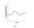
- FIG. 3 shows an example of changes in the input weight (dust input speed) thus obtained.
- the loading speed changes with time.
- the area between the horizontal axis and the graph corresponds to the total weight of the waste that has been thrown into the hopper 20 from the start time of throwing refuse of the day to the present time.
- the base component of the dust supply speed derived by the base component deriving unit 62 is used by the supply speed estimating unit 66 described later.
- the specific gravity estimation unit 63 based on the above-described input weight W1 and the volume (hereinafter, referred to as “input volume”) V1 of the waste input to the hopper 20, collects the waste immediately before being supplied into the incinerator 40. Estimate the specific gravity ⁇ 2.
- the specific gravity estimation unit 63 calculates the input volume V1 based on the measurement values of the height measuring device 16 immediately before and immediately after the dust is input to the hopper 20.
- the relationship between the surface height measured by the height measuring device 16 and the total volume of dust stored in the hopper 20 is determined by a storage device of the control device 60 or a storage device provided outside the control device 60. It is stored in advance (not shown).
- the specific gravity estimation unit 63 measures the total volume corresponding to the measurement value of the height measuring device 16 immediately after the dust is put into the hopper 20 and the total volume corresponding to the measurement value of the height measuring device 16 immediately before the dust is put into the hopper 20.
- the input volume V1 is derived from the difference in volume.
- the calculation of the input volume V1 by the specific gravity estimation unit 63 is not limited to this.
- the specific gravity estimation unit 63 may calculate the input volume V1 by the product of the amount of change in the surface height of the dust in the hopper 20 before and after the dust is input into the hopper 20 and the cross-sectional area of the hopper 20. ..
- the specific gravity estimating unit 63 calculates the specific gravity ⁇ 1 of the dust thrown into the hopper 20 from the calculated input volume V1 and the input weight W1 of the dust.
- the calculated specific gravity ⁇ 1 of the dust is stored in a storage unit of the control device 60 or a storage device (not shown) provided outside the control device 60.
- the specific gravity ⁇ 1 of the dust is stored in association with, for example, the time when the dust is thrown into the hopper 20 and the order in which the dust is thrown so that it can be identified when the specific gravity of the dust is thrown into the hopper 20.
- the specific gravity estimation unit 63 calculates and stores the specific gravity ⁇ 1 of the dust thrown into the hopper 20 every time the crane 13 throws dust.
- data such as the input weight W1 and the input volume V1 that can derive the specific gravity ⁇ 1 of the waste may be stored.
- the specific gravity estimating unit 63 causes the input weight W1 and the input volume V1 of the dust that has been input to the hopper 20 in the past predetermined time (from the input weight W1 and the input volume V1 detected in the previous predetermined time). Based on the calculated waste specific gravity ⁇ 1), the specific gravity ⁇ 2 of the waste just before being supplied into the incinerator 40 is calculated. For example, the specific gravity estimation unit 63 may calculate the average value ⁇ AVE of the specific gravity ⁇ 1 of the waste thrown into the hopper 20 in the past predetermined time as the specific gravity ⁇ 2 of the waste just before being supplied into the incinerator 40. Good.
- the residence time of the dust in the hopper 20, that is, after the dust is thrown into the hopper 20 is taken into consideration.
- the dust retention time in the hopper 20 varies depending on the surface shape of the dust stored in the hopper 20, the property of the dust in the hopper 20, and the like. Variations are also taken into account. That is, the specific gravity estimation unit 63 is preset with a time range (for example, 40 minutes) as the residence time of the dust in the hopper 20, and the specific gravity estimation unit 63 selects from the stored dust specific gravity ⁇ 1.
- the specific gravity of the waste within the set time range is extracted, and the value calculated from the extracted specific gravity (for example, their average value ⁇ AVE ) is used as the specific gravity ⁇ 2 of the waste immediately before being supplied into the incinerator 40. Set.
- the method of estimating the specific gravity ⁇ 2 of refuse by the specific gravity estimating unit 63 is not limited to this. For example, without using a preset residence time, it is calculated whether or not the dust immediately before being supplied into the furnace by the dust supply device 30 corresponds to the one that was thrown into the hopper 20 i times ago, and i
- the specific gravity of the refuse before the turning may be derived as the specific gravity of the refuse immediately before being supplied into the furnace. Further, when the specific gravity of the waste put in the hopper 20 can be roughly grasped from the quality of the waste stored in the pit 10, etc., the specific gravity ⁇ 2 of the waste just before being supplied into the incinerator 40 is previously calculated.
- the set design gravity may be used. In this case, the control device 60 does not need to have the specific gravity estimation unit 63.
- the supply volume calculation unit 64 is supplied into the incinerator 40 based on the change in the surface height measured by the height measuring device 16 immediately before and immediately after the dust is supplied into the incinerator 40 by the dust supply device 30.
- the supply volume V2 of dust is calculated.
- the supply volume calculation unit 64 calculates the supply volume V2 of dust by the same method as the calculation of the input volume V1 by the specific gravity estimation unit 63. That is, the relationship between the surface height measured by the height measuring device 16 and the total volume of dust stored in the hopper 20 is determined by the storage unit of the control device 60 or a storage device provided outside the control device 60 (not shown). ) Is stored in advance.
- the supply volume calculation unit 64 calculates the supply volume V2 from the difference in total volume corresponding to the measurement value of the height measuring device 16 immediately before and immediately after one reciprocating operation of the pusher 31.
- the supply volume calculation unit 64 uses the total volume corresponding to the measurement value of the height measuring device 16 immediately after the dust is supplied to the incinerator 40 and the height measuring device immediately before the dust is supplied to the incinerator 40.
- the supply volume V2 is derived from the total volume difference corresponding to the 16 measured values.
- the method of calculating the supply volume V2 by the supply volume calculation unit 64 is not limited to this.
- the supply volume calculation unit 64 calculates the supply volume V2 from the product of the amount of change in the surface height of the waste in the hopper 20 before and after supplying the waste into the incinerator 40 and the cross-sectional area of the hopper 20. Good.
- the fluctuation component deriving unit 65 estimates the transition of the weight W2 of the dust supplied to the incinerator 40 by the dust supply device 30 from the change in the surface height measured by the height measuring device 16. Further, the fluctuation component deriving unit 65 derives the fluctuation of the estimated transition of the supply weight W2 as the fluctuation component of the dust supply speed based on the base component derived by the base component deriving unit 62.
- a method of deriving the fluctuation component by the fluctuation component deriving unit 65 will be described with reference to FIGS. 4A and 4B.
- the fluctuation component deriving unit 65 estimates a value obtained by multiplying the specific gravity ⁇ 2 of the waste estimated by the specific gravity estimating unit 63 by the supply volume V2 calculated by the supply volume calculating unit 64 as the supply weight W2.
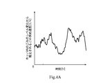
- An example of the transition of the supplied weight W2 thus obtained is shown in FIG. 4A.
- the area between the abscissa and the graph corresponds to the total weight supplied from the start time of throwing refuse in one day to the present time, but the quantitative accuracy is poor.
- the fluctuation component deriving unit 65 extracts a fluctuation according to the dust supply operation of the dust collector 30 from the estimated transition of the supply weight W2. Specifically, the fluctuation component deriving unit 65 performs filter processing on the transition of the supplied weight W2 shown in FIG. 4A using a high-pass filter or a band-pass filter having frequency characteristics according to the dust supply operation of the dust collector 30. Execute.
- the high-pass filter or the band-pass filter having a frequency characteristic according to the dust supply operation of the dust collector 30 is a filter that allows fluctuations occurring at every supply interval of the dust collector 30 to pass. An example of the result of the filter processing thus obtained is shown in FIG. 4B.
- the fluctuation component deriving unit 65 uses the result obtained by the filtering process as the fluctuation component of the dust supply speed.
- the area between the horizontal axis and the graph above the horizontal axis is substantially the same as the area between the horizontal axis and the graph below the horizontal axis.
- the supply speed estimating unit 66 estimates the transition of the waste supply speed by superposing the fluctuation component derived by the fluctuation component deriving unit 65 on the base component derived by the base component deriving unit 62.
- the supply speed estimation unit 66 determines the time axis of the base component and the fluctuation component according to the residence time of the dust in the hopper 20 from the time when the crane 13 throws the hopper 20 to the bottom of the hopper 20. Adjust the time axis of.
- the supply speed estimation unit 66 performs a moving average process with a time width according to the residence time of dust in the hopper 20 on the transition of the input weight W1 to obtain the time axis of the base component. Is aligned with the time axis of the fluctuation component. Specifically, by performing a moving average process with a time width about twice as long as the residence time (for example, 40 minutes) with respect to the transition of the input weight W1, a graph delayed by about the residence time is obtained. Can be adjusted to the time axis of the fluctuation component.
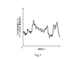
- FIG. 5 is a graph obtained by superimposing the variation component shown in FIG. 4B on the moving average result of the base component shown in FIG.
- the supply speed estimation unit 66 estimates the result thus obtained as a time transition of the waste supply speed.
- the dust control unit 67 uses the waste supply rate obtained by the supply rate estimating unit 66 as a control index so that the incineration weight plan of the incinerator 40 is adhered to in accordance with a predetermined daily waste incineration weight plan.
- the dust supply device 30 is controlled so that the combustion state is stable.
- the dust supply control unit 67 controls, for example, part or all of the moving speed of the pusher 31 of the dust supply device 30, the number of movements per unit time, the stroke (moving amount), and the position of the stroke end.
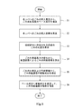
- FIG. 6 is a flowchart showing the flow of the dust supply speed estimation processing by the control device 60 of the present embodiment.
- the base component deriving unit 62 derives the transition of the weight of the waste put into the hopper 20 as the base component of the waste supply speed (S1: base component deriving step).
- the specific gravity estimation unit 63 calculates the charging volume V1 of the dust thrown into the hopper 20 based on the change in the measurement value of the height measuring device 16 immediately before and immediately after the dust is thrown into the hopper 20 ( S2: Input volume calculation step).
- the specific gravity estimation unit 63 calculates the specific gravity ⁇ 2 of the dust immediately before being supplied into the incinerator 40 based on the input weight W1 of the dust input to the hopper 20 and the input volume V1 (S3: specific gravity calculation). Step).
- the supply volume calculation unit 64 calculates the supply volume V2 of the dust supplied into the incinerator 40 based on the change in the surface height measured by the height measuring device 16 (S4: supply volume calculation step). ).
- the fluctuation component deriving unit 65 estimates a value obtained by multiplying the specific gravity ⁇ 2 of the waste estimated by the specific gravity estimating unit 63 by the supply volume V2 calculated by the supply volume calculating unit 64 as the supply weight W2. Further, the fluctuation component deriving unit 65 derives the fluctuation of the estimated transition of the supply weight W2 as a fluctuation component of the dust supply speed with the base component as a reference (S5: fluctuation component deriving step).
- the supply speed estimation unit 66 estimates the transition of the waste supply speed by combining the base component with the variable component (S6: supply speed estimation step).
- the above-described base component derivation step S1 may be executed at any time before the supply speed estimation step S6, for example, immediately before the supply speed estimation step S6.
- the transition of the supply speed of the dust is divided into the base component and the variation component with the base component as a reference, and these are combined. Estimated by.
- the base component is derived from the change in the weight of garbage measured by the scale 15.
- the dust thrown into the hopper 20 by the crane 13 is temporarily stored in the hopper 20 and then fed into the incinerator 40 by the dust supply device 30.
- the weight of the dust put into the hopper 20 by the crane 13 can be regarded as the weight of the dust supplied into the incinerator 40 by the dust supply device 30.
- the measurement value of the weighing scale 15 is more accurate than the volume of the dust obtained from the measurement value of the height measuring device 16, and therefore the integrated value for a long time (for example, 24 hours) is also accurate. Therefore, the waste weight measured by the weight scale 15 is suitable as a control index for adhering to a predetermined daily waste incineration weight plan.
- the fluctuation component is a fluctuation in the weight of refuse supplied to the incinerator 40, which is obtained from a change in the surface height measured by the height measuring device 16.
- the volume of dust obtained from the change in surface height measured by the height measuring device 16 has poor quantitative accuracy.
- the change in the surface height measured by the height measuring device 16 can capture a short-term change in the weight of the refuse supplied to the incinerator 40, and dust can be supplied in accordance with the short-term change.
- the stabilization of the incineration state in the incinerator 40 can be improved.
- control device 60 by combining the above-described base component and variable component, the adherence to the predetermined daily incineration weight plan for refuse and the stabilization of the incineration state in the incinerator 40 are achieved. It is possible to estimate the weight of the refuse supplied to the incinerator 40 per unit time, which is a control index for achieving both.
- the fluctuation component deriving unit 65 extracts a fluctuation corresponding to the dust supply operation of the dust supply device 30 from the estimated transition of the supplied weight, and uses the extracted fluctuation as a fluctuation component of the dust supply speed based on the base component. Derive. According to this configuration, it is possible to reduce fluctuations other than fluctuations in accordance with the operation of the dust supply device 30, from changes in the dust supply speed estimated based on changes in the surface height measured by the height measuring device 16. ..
- the fluctuation component deriving unit 65 executes a filtering process using a high-pass filter or a band-pass filter having a frequency characteristic according to the dust supply operation of the dust supply device 30 on the transition of the supplied weight, and the result of the filter process is Since it is the fluctuation component of the dust supply speed, it is possible to easily extract the fluctuation according to the operation of the dust supply device 30 from the transition of the dust supply speed estimated based on the change in the surface height measured by the height measuring device 16. ..
- the supply speed estimation unit 66 determines the time axis of the base component and the time axis of the fluctuation component according to the residence time of the dust in the hopper 20 from the time when the crane 13 throws the hopper 20 to the bottom of the hopper 20. You may adjust and. With this configuration, it is possible to accurately estimate the transition of the refuse supply speed.
- the supply speed estimation unit 66 executes a moving average process on the transition of the input weight W1 in a time width corresponding to the residence time, thereby aligning the time axis of the base component with the time axis of the fluctuation component. Therefore, it is possible to make the time change of the base component of the refuse supply rate gentle so that the transition of the refuse supply rate finally obtained by the supply rate estimation unit 66 can be easily used for control.
- the height measuring device 16 is an ultrasonic level meter, but the height measuring device of the present invention is not limited to this.
- the height measuring device of the present invention may be a scanning laser type level meter.
- the supply speed estimation unit 66 executes the moving average process in the time width corresponding to the retention time of the dust in the hopper 20 with respect to the transition of the input weight W1 to obtain the base component.
- the time axis is adjusted to the time axis of the fluctuation component, the method of adjusting the time is not limited to this.
- the time axis of the base component may be aligned with the time axis of the fluctuation component by shifting the graph of the base component by the residence time.
- Incinerator 10 Pit 13: Crane 14: Bucket 15: Weighing scale 16: Height measuring device 20: Hopper 30: Dust collector 40: Incinerator 60: Control device (dust supply speed estimation device) 62: Base component derivation unit 65: Fluctuation component derivation unit 66: Supply rate estimation unit
Landscapes
- Engineering & Computer Science (AREA)
- Mechanical Engineering (AREA)
- General Engineering & Computer Science (AREA)
- Incineration Of Waste (AREA)
- Environmental & Geological Engineering (AREA)
Abstract
ごみ供給速度推定装置は、ホッパに投入されたごみを、給塵装置により焼却炉内に順次供給する焼却設備において、給塵装置により焼却炉内に供給されるごみの単位時間あたりの重量であるごみ供給速度の推移を推定する装置であって、ホッパへのごみの投入重量の推移を、ごみ供給速度のベース成分として導出するベース成分導出部と、ホッパ内のごみの表面高さの変化から、給塵装置により焼却炉内に供給されるごみの供給重量の推移を推定するとともに、推定した供給重量の推移の変動を、ベース成分を基準とするごみ供給速度の変動成分として導出する変動成分導出部と、ベース成分に変動成分を重畳することにより、ごみ供給速度の推移を推定する供給速度推定部と、を備える。
Description
本発明は、産業廃棄物等のごみを焼却処理する焼却設備において、単位時間あたりに焼却炉内に供給されるごみ重量(以下、「ごみ供給速度」という。)を推定するごみ供給速度推定装置およびごみ供給速度推定方法に関する。
従来から、ホッパにてごみを一時的に貯留し、当該ホッパの底部に到達したごみを、給塵装置で焼却炉内に順次供給する焼却設備が知られている。このような焼却設備では、焼却炉内で発生する廃熱をボイラにより回収している。ボイラで熱回収を効率的に行うためには、焼却炉内のごみの燃焼状態を安定させることが重要である。焼却炉内でのごみの燃焼状態の安定化を向上させるよう給塵装置を制御する技術が従来から提案されている。
例えば特許文献1には、給塵装置により焼却炉内に供給されるごみの供給熱量を計測できる計測装置を備えた焼却設備が開示されている。この焼却設備では、ホッパ上方に設置された走査型レーザー式レベル計によりホッパ内のごみの表面の高さ位置を計測しており、計測したごみの表面の高さ位置の変化から、ホッパに投入したごみの容積(投入ごみ容積)や単位時間当たりに焼却炉内に供給されたごみの容積(ごみ移動容積)を演算する。また、ホッパにごみを投入するクレーンに取り付けられた重量計により、ホッパに投入したごみ重量を検出する。検出したごみ重量と演算して求めた投入ごみ容積とから、ホッパに投入したごみの比重を算出する。さらに、算出したごみ比重と単位時間当たりに焼却炉内に供給された上述のごみ移動容積とから、単位時間当たりに焼却炉内に供給されるごみの供給熱量を演算する。演算したごみの供給熱量は、給塵装置を制御する制御装置に送られる。制御装置は、受信したごみの供給熱量を制御の指標として、単位時間当たりのごみの供給熱量が一定となるように給塵装置を制御する。
ところで、焼却設備では、1日当たりのごみの焼却重量が予め計画されている。このため、給塵装置は、炉内に供給したトータルのごみ重量を監視しながら、計画された焼却重量に到達するよう制御される必要がある。上述した特許文献1の焼却設備では、焼却炉内の燃焼状態を安定させるように給塵装置が制御されるが、予め定めた1日当たりのごみの焼却重量計画を順守させることについては考慮されていない。
ただし、特許文献1の焼却設備では、上述したように、焼却炉内に供給されるごみの容積や比重を算出している。これらの値の積であるごみ重量を積算することにより、焼却炉内に供給したトータルのごみ重量を監視することは可能である。しかしながら、これらのごみの容積やごみの比重は、ホッパ内のごみのレベル変化から算出しているため、いずれも定量的な精度が悪く、これらの値から得られる長時間(例えば24時間)の積算値は正確性に欠けるという問題がある。このため、予め定めた1日当たりのごみの焼却重量計画の順守と焼却炉内の焼却状態の安定化を両立させる制御指標が望まれる。
そこで、本発明は、予め定めた1日当たりのごみの焼却重量計画の順守と、焼却炉内の焼却状態の安定化を両立させる制御指標となるごみ供給速度を推定することができるごみ供給速度推定装置およびごみ供給速度推定方法を提供することを目的とする。
上記課題を解決するために、本発明の一態様に係るごみ供給速度推定装置は、ごみを焼却する焼却炉と、上方から投入されたごみを貯留するホッパと、ごみを掴むバケットおよび前記バケットに掴まれたごみの重量を計測する重量計を有し、ピット内のごみを前記ホッパへ投入するクレーンと、前記ホッパ内のごみの表面高さを計測する高さ計測装置と、前記ホッパの下部において前記焼却炉内にごみを供給する給塵装置と、を備える焼却設備において、前記給塵装置により前記焼却炉内に供給されるごみの単位時間あたりの重量であるごみ供給速度の推移を推定するごみ供給速度推定装置であって、前記重量計の計測値から得られる前記ホッパへのごみの投入重量の推移を、ごみ供給速度のベース成分として導出するベース成分導出部と、前記高さ計測装置で計測される前記表面高さの変化から、前記給塵装置により前記焼却炉内に供給されるごみの供給重量の推移を推定するとともに、推定した前記供給重量の推移の変動を、前記ベース成分を基準とするごみ供給速度の変動成分として導出する変動成分導出部と、前記ベース成分に前記変動成分を重畳することにより、ごみ供給速度の推移を推定する供給速度推定部と、を備える。
上記の構成では、ごみの供給速度の推移を、ベース成分と当該ベース成分を基準とする変動成分とに分けて導出し、それらを組み合わせることにより推定する。
ベース成分は、重量計で計測されるごみ重量の推移から導出する。クレーンによりホッパに投入されるごみは、一時的にホッパに貯留された後に、給塵装置により焼却炉内に供給される。このため、長期的に見れば、クレーンによりホッパに投入されるごみ重量は、給塵装置により焼却炉内に供給されるごみ重量とみなせる。さらに、重量計の計測値は、高さ計測装置の計測値から求まるごみの容積に比べて正確であり、よって長時間(例えば24時間)の積算値も正確である。このため、重量計で計測されるごみ重量は、予め定めた1日当たりのごみの焼却重量計画を順守させるための制御指標として好適である。
また、変動成分は、高さ計測装置で計測されるホッパ内のごみの表面高さの変化から求めた炉内へのごみの供給重量の変動である。上述したように、高さ計測装置で計測される表面高さの変化から求まるごみの容積は、定量的な精度が悪い。しかし、高さ計測装置で計測される表面高さの変化は、炉内に供給されるごみの供給重量の短期的な変動を捉えることができ、この短期的変動に応じて給塵装置を制御することで、焼却炉内の焼却状態の安定化を向上させることができる。
従って、ベース成分に変動成分を重畳することにより、予め定めた1日当たりのごみの焼却重量計画の順守と、焼却炉内の焼却状態の安定化を両立させる制御指標となる、単位時間あたりに焼却炉内に供給されるごみ重量を推定できる。
上記の構成において、前記変動成分導出部は、前記給塵装置により前記焼却炉内にごみが供給される直前と直後の前記高さ計測装置で計測される前記表面高さの変化に基づき算出した、前記焼却炉内に供給したごみの供給容積と、前記高さ計測装置で計測される前記表面高さの変化から推定したまたは予め設定したごみの比重とを掛けた値を、前記供給重量として推定してもよい。
上記の構成において、前記変動成分導出部は、推定した前記供給重量の推移から前記給塵装置のごみ供給動作に応じた変動を抽出し、抽出した変動を、前記ベース成分を基準とするごみ供給速度の変動成分として導出してもよい。この構成によれば、高さ計測装置で計測される表面高さの変化に基づき推定したごみ供給速度の推移から、給塵装置の動作に応じた変動以外の変動を低減することができる。
上記の構成において、前記変動成分導出部は、前記供給重量の推移に対して、前記給塵装置のごみ供給動作に応じた周波数特性のハイパスフィルタまたはバンドパスフィルタによるフィルタ処理を実行し、前記フィルタ処理の結果を、ごみ供給速度の前記変動成分としてもよい。この構成によれば、高さ計測装置で計測される表面高さの変化に基づき推定したごみ供給速度の推移から、給塵装置の動作に応じた変動を容易に抽出できる。
上記の構成において、前記供給速度推定部は、前記クレーンにより前記ホッパに投入されてから前記ホッパの下部に至るまでの前記ホッパ内のごみの滞留時間に応じて、前記ベース成分の時間軸と前記変動成分の時間軸とを調整してもよい。この構成によれば、ごみ供給速度の推移を精度良く推定できる。
上記の構成において、前記供給速度推定部は、前記重量計で計測されるごみ重量の推移に対して、前記滞留時間に応じた時間幅での移動平均処理を実行することにより、前記ベース成分の時間軸を、前記変動成分の時間軸に合わせてもよい。この構成によれば、移動平均処理を実行することで、ごみ供給速度のベース成分の時間変化を緩やかにして、最終的に供給速度推定部により得られるごみ供給速度の推移を制御に使用しやすいものとすることができる。
また、本発明の一態様に係るごみ供給速度推定方法は、ホッパに投入されたごみを、給塵装置により焼却炉内に順次供給する焼却設備において、前記給塵装置により前記焼却炉内に供給されるごみの単位時間あたりの重量であるごみ供給速度の推移を推定するごみ供給速度推定方法であって、前記ホッパへのごみの投入重量の推移を、ごみ供給速度のベース成分として導出するベース成分導出ステップと、前記高さ計測装置で計測される前記表面高さの変化から、前記給塵装置により前記焼却炉内に供給されるごみの供給重量の推移を推定するとともに、推定した前記供給重量の推移の変動を、前記ベース成分を基準とするごみ供給速度の変動成分として導出する変動成分導出ステップと、前記ベース成分に前記変動成分を重畳することにより、ごみ供給速度の推移を推定する供給速度推定ステップと、を含む。
本発明によれば、予め定めた1日当たりのごみの焼却重量計画の順守と、焼却炉内の焼却状態の安定化を両立させる制御指標となるごみ供給速度を推定することができるごみ供給速度推定装置およびごみ供給速度推定方法を提供することができる。
以下、本発明の一実施形態について、図を参照しながら説明する。
図1は、焼却設備100の全体構成を示す概略構成図である。図1に示すように、焼却設備100は、ピット10と、ホッパ20と、給塵装置30と、焼却炉40と、ボイラ50と、制御装置60とを備えている。
ピット10には、焼却設備100に運搬されてきたごみが投入され、貯留される。ピット10は、ごみが貯留される貯留空間11と、その上側で貯留空間11と連続する、貯留空間11に貯留されたごみがホッパ20に搬送される搬送空間12とを有している。ピット10の搬送空間12には、所定の投入間隔でピット10内のごみをホッパ20へ投入するクレーン13が設けられている。クレーン13は、ピット10内のごみを掴むバケット14を有しており、バケット14に掴まれたごみをホッパ20の上方に搬送してホッパ20に投入する。また、クレーン13は、バケット14に掴まれ、搬送されるごみの重量を計測する重量計15を有する。
また、ピット10の搬送空間12には、ホッパ20に貯留されたごみの表面の高さ(以下、「ごみ高さ」とも呼ぶ。)を計測する高さ計測装置16が設けられている。高さ計測装置16は、ピット10の搬送空間12に配置されている。高さ計測装置16は、例えば超音波式のレベル計である。
ホッパ20は、クレーン13により上方から投入されたごみを一時的に貯留するとともに、下方へと順次供給する。クレーン13により上方から投入されるたびに、ホッパ20内には、ごみが積層される。ホッパ20へのごみ投入直後のごみ高さは、ホッパ20へのごみ投入直前のものに比べて増加する。一方、ホッパ20内の底部分のごみは、ホッパ20の底部に設けられた給塵装置30によって随時焼却炉40内に供給される。このため、給塵装置30によるごみ供給直後のごみ高さは、給塵装置30によるごみ供給直前のものに比べて減少する。
給塵装置30は、ホッパ20の下部に設けられており、ホッパ20へのごみの投入間隔より短い時間間隔(供給間隔)で、ホッパ20に投入されたごみを焼却炉40内に供給する。給塵装置30は、水平方向に往復するプッシャ31と、プッシャ31を往復駆動する駆動装置32とを有している。駆動装置32は、例えば油圧シリンダであり、ホッパ20に対して焼却炉40とは反対側に配置されている。但し、駆動装置32は、ホッパ20に対して焼却炉40とは反対側に配置されていなくてもよい。例えば、駆動装置32は、焼却炉40側から見てプッシャ31と横並びに配置されていてもよい。プッシャ31は、略直方体状であって、ホッパ20の底部分で往復駆動する。そして、プッシャ31は、ホッパ20内のごみを焼却炉40の入口40aに向かって順次押し出すことによって焼却炉40内にごみを供給する。給塵装置30は、後述する制御装置60により制御される。
焼却炉40では、ごみを搬送しながら焼却する。焼却炉40は、上流側から順に、主燃焼室41と、主燃焼室41と連続する再燃焼室42とを有している。また、焼却炉40は、ストーカ式焼却炉であり、焼却炉40における主燃焼室41および再燃焼室42の下方には、上流側から順に、ごみの搬送手段としての、乾燥ストーカ43、燃焼ストーカ44および後燃焼ストーカ45が設けられている。主燃焼室41には、ストーカ43~45越しに一次空気が供給されるとともに、ストーカ43~45の上方で二次空気が供給される。また、主燃焼室41には、焼却炉40から排出された排ガスが供給される。排ガスは、酸素濃度が空気より低いので、燃焼温度の局所的な過上昇を抑えるために主燃焼室41に供給される。本実施形態では、ボイラ50を通過した排ガスの一部が、主燃焼室41に戻される。
給塵装置30により焼却炉40内に供給されたごみは、まず乾燥ストーカ43に送られ、一次空気および主燃焼室41の輻射熱により乾燥される。乾燥ストーカ43において乾燥されたごみは、乾燥ストーカ43により燃焼ストーカ44に送られ燃焼され、火炎が発生する。燃焼ストーカ44におけるごみおよび燃焼により発生した灰は、燃焼ストーカ44により後燃焼ストーカ45に送られる。後燃焼ストーカ45では、燃焼ストーカ44にて燃焼しきれなかった未燃焼分のごみが燃焼され、ごみの燃焼後の灰は、後燃焼ストーカ45に隣接して設けられたシュート46から排出される。
また、主燃焼室41では、ごみの熱分解および部分酸化反応により燃焼ガスが生成され、この燃焼ガスがごみと共に燃焼される。再燃焼室42では、主燃焼室41から流入した燃焼ガスが完全燃焼される。本実施形態の焼却炉40は、燃焼ガスとごみが並行して流れる並行流焼却炉である。但し、焼却炉40は、燃焼ガスとごみが異なる方向に流れる方式の焼却炉(例えば、中間流焼却炉)であってもよい。また、焼却炉40は、ストーカ式でなくてもよく、例えばキルン式であってもよい。
ボイラ50は、ごみの燃焼によって発生した熱を利用して蒸気を生成する部分である。ボイラ50は、流路壁に設けられた多数の水管51および過熱器管52で熱交換を行うことにより蒸気(過熱蒸気)を生成し、生成した蒸気は図外の蒸気タービン発電機に供給されて発電が行われる。ボイラ50を通過した排ガスの大部分は、排ガス処理設備(図示せず)を経由し、煙突(図示せず)から大気中へ放出され、ボイラ50を通過した排ガスの一部が、上述したように主燃焼室41に戻される。
制御装置60は、焼却設備100における給塵装置30を制御する。また、本実施形態において、制御装置60は、重量計15および高さ計測装置16の各々から計測値を受信し、受信した計測値に基づき、ごみ供給速度を推定する。すなわち、制御装置60は、本発明のごみ供給速度推定装置としても機能する。
図2は、焼却設備100の制御系のブロック図である。制御装置60は、重量計15および高さ計測装置16から計測信号を受信し、給塵装置30に制御信号を送信する。制御装置60は、機能的ブロックとして、データ記録部61、ベース成分導出部62、比重推定部63、供給容積算出部64、変動成分導出部65、供給速度推定部66および給塵制御部67を有している。制御装置60は、例えばコンピュータであって、ROM、RAM等の記憶部、および当該記憶部に記憶された所定のプログラムを実行するCPU等の演算処理部を有しており、例えばこれら制御装置60の記憶部および/または演算処理部が、上述の各機能部を構成する。なお、制御装置60は単一のコンピュータによる集中制御により各処理を実行してもよいし、複数のコンピュータの協働による分散制御により各処理を実行してもよい。
データ記録部61は、重量計15から取得した計測値を、制御装置60の記憶部あるいは制御装置60の外部に設けられた記憶装置(図示略)に記録する。また、データ記録部61は、高さ計測装置16から取得した計測値を、制御装置60の記憶部あるいは制御装置60の外部に設けられた記憶装置(図示略)に記録する。
ベース成分導出部62は、ホッパ20に投入されるごみの重量(以下、「投入重量」ともいう。)W1の推移を、ごみ供給速度のベース成分として導出する。以下では、ベース成分導出部62によるベース成分の導出方法について、図3を参照して説明する。
まずベース成分導出部62は、1日のごみの投入開始時刻から現時点までのホッパ20へのごみの投入重量W1を積算する。言い換えれば、ベース成分導出部62は、1日のごみの投入開始時刻から現時点までにデータ記録部61が記録した重量計15の計測値を積算する。
また、ベース成分導出部62は、算出した積算値の時間変化、すなわち、ホッパ20への単位時間当たりのごみの投入重量(以下、「ごみ投入速度」ともいう。)を導出する。こうして得られる投入重量(ごみ投入速度)の推移の一例を図3に示す。図3に示すように、バケット14で掴まれるごみの容積やごみ質などは投入毎に異なるため、投入速度は経時的に変化している。なお、横軸とグラフの間の面積は、1日のごみの投入開始時刻から現時点までにホッパ20に投入されたトータルの投入重量に対応する。こうして、ベース成分導出部62により導出されたごみ供給速度のベース成分は、後述する供給速度推定部66にて使用される。
比重推定部63は、上述の投入重量W1と、ホッパ20に投入されたごみの容積(以下、「投入容積」という。)V1とに基づいて、焼却炉40内に供給される直前のごみの比重ρ2を推定する。
比重推定部63によるごみの比重の推定方法について、詳しく説明する。まず比重推定部63は、ホッパ20にごみが投入される直前と直後の高さ計測装置16の計測値に基づいて投入容積V1を算出する。本実施形態では、高さ計測装置16により計測された表面高さとホッパ20に貯留されたごみの総容積との関係が、制御装置60の記憶部あるいは制御装置60の外部に設けられた記憶装置(図示略)に予め記憶されている。比重推定部63は、ホッパ20へごみを投入した直後の高さ計測装置16の計測値に対応する総容積とホッパ20へごみを投入する直前の高さ計測装置16の計測値に対応する総容積の差から、投入容積V1を導き出す。
なお、比重推定部63による投入容積V1の算出は、これに限らない。例えば、比重推定部63は、ホッパ20内にごみを投入する前後のホッパ20内のごみの表面高さ変化量と、ホッパ20の断面積との積により、投入容積V1を算出してもよい。
次に、比重推定部63は、算出した投入容積V1と、ごみの投入重量W1から、ホッパ20に投入されたごみの比重ρ1を算出する。算出されたごみの比重ρ1は、制御装置60の記憶部あるいは制御装置60の外部に設けられた記憶装置(図示略)に記憶される。ごみの比重ρ1は、いつホッパ20に投入したごみの比重であるかが識別できるように、例えばホッパ20に投入した時間や投入した順番等と関連付けて記憶される。こうして、比重推定部63は、ホッパ20に投入されたごみの比重ρ1をクレーン13によるごみの投入ごとに算出および記憶していく。但し、投入重量W1および投入容積V1から算出されたごみの比重ρ1の代わりに、例えば投入重量W1および投入容積V1等、ごみの比重ρ1を導き出せるデータが記憶されてもよい。
本実施形態では、比重推定部63は、過去の所定時間内にホッパ20に投入されたごみの投入重量W1および投入容積V1(過去の所定時間内に検出された投入重量W1および投入容積V1から算出されたごみ比重ρ1を含む。)に基づいて、焼却炉40内に供給される直前のごみの比重ρ2を算出している。例えば、比重推定部63は、過去の所定時間内にホッパ20に投入されたごみの比重ρ1の平均値ρAVEを、焼却炉40内に供給される直前のごみの比重ρ2として算出してもよい。
より詳しく説明すれば、本実施形態では、焼却炉40内に供給される直前のごみの比重ρ2の算出には、ホッパ20内でのごみの滞留時間、すなわちホッパ20にごみが投入されてから焼却炉40に供給されるまでの時間差が考慮されている。また、ホッパ20内でのごみ滞留時間は、ホッパ20に貯留されたごみの表面形状やホッパ20内のごみの性状等によりばらつきがあり、本実施形態では、ごみの比重ρ2の算出に、このばらつきも考慮されている。すなわち、比重推定部63には、ホッパ20内でのごみの滞留時間としての時間範囲(例えば40分)が予め設定されており、比重推定部63は、上記記憶されたごみ比重ρ1の中から、設定された時間範囲内のごみ比重を抽出して、抽出された比重から算出された値(例えばそれらの平均値ρAVE)を、焼却炉40内に供給される直前のごみの比重ρ2として設定する。
比重推定部63によるごみの比重ρ2の推定方法は、これに限られない。例えば、予め設定した滞留時間を使用せずに、給塵装置30により炉内に供給される直前のごみが、ホッパ20にi回前に投入されたものに対応するかを演算して、i回前のごみの比重を、炉内に供給される直前のごみの比重として導出してもよい。また、ホッパ20に投入されるごみの比重が、ピット10内に貯留されたごみ質などから凡そ把握可能である場合には、焼却炉40内に供給される直前のごみの比重ρ2は、予め設定した設計比重としてもよい。この場合、制御装置60は、比重推定部63を有する必要はない。
供給容積算出部64は、給塵装置30により焼却炉40内にごみが供給される直前と直後の高さ計測装置16で計測される表面高さの変化に基づき、焼却炉40内に供給されたごみの供給容積V2を算出する。
具体的には、供給容積算出部64は、比重推定部63による投入容積V1の算出と同様の方法で、ごみの供給容積V2を算出する。すなわち、高さ計測装置16により計測された表面高さとホッパ20に貯留されたごみの総容積との関係が、制御装置60の記憶部あるいは制御装置60の外部に設けられた記憶装置(図示略)に予め記憶されている。供給容積算出部64は、プッシャ31の一回の往復動作の直前と直後の高さ計測装置16の計測値に対応する総容積の差から、供給容積V2を算出する。言い換えれば、供給容積算出部64は、焼却炉40内へのごみの供給直後の高さ計測装置16の計測値に対応する総容積と焼却炉40内へのごみの供給直前の高さ計測装置16の計測値に対応する総容積の差から、供給容積V2を導き出す。
なお、供給容積算出部64による供給容積V2の算出方法は、これに限らない。例えば、供給容積算出部64は、焼却炉40内にごみを供給する前後のホッパ20内のごみの表面高さ変化量と、ホッパ20の断面積との積により、供給容積V2を算出してもよい。
変動成分導出部65は、高さ計測装置16で計測される表面高さの変化から、給塵装置30により焼却炉40内に供給されるごみの供給重量W2の推移を推定する。また、変動成分導出部65は、推定した供給重量W2の推移の変動を、ベース成分導出部62が導出したベース成分を基準とするごみ供給速度の変動成分として導出する。
変動成分導出部65による変動成分の導出方法について、図4Aおよび4Bを参照して説明する。
変動成分導出部65は、比重推定部63により推定されたごみの比重ρ2と、供給容積算出部64により算出した供給容積V2とを掛けた値を、供給重量W2として推定する。こうして得られる供給重量W2の推移の一例を図4Aに示す。なお、横軸とグラフの間の面積は、1日のごみの投入開始時刻から現時点までのトータルの供給重量に対応するが、定量的な精度が悪い。
さらに、変動成分導出部65は、推定した供給重量W2の推移から、給塵装置30のごみ供給動作に応じた変動を抽出する。具体的には、変動成分導出部65は、図4Aに示した供給重量W2の推移に対して、給塵装置30のごみ供給動作に応じた周波数特性のハイパスフィルタまたはバンドパスフィルタによるフィルタ処理を実行する。給塵装置30のごみ供給動作に応じた周波数特性のハイパスフィルタまたはバンドパスフィルタとは、言い換えれば、給塵装置30の供給間隔おきに生じる変動を通過させるフィルタである。こうして得られるフィルタ処理の結果の一例を図4Bに示す。ハイパスフィルタまたはバンドパスフィルタによるフィルタ処理により、給塵装置30のごみ供給動作に応じたホッパ20内のごみの表面高さの増減(つまり、炉内へのごみの供給重量の増減)を抽出することができる。変動成分導出部65は、フィルタ処理により得られた結果をごみ供給速度の変動成分とする。なお、横軸と当該横軸より上側のグラフの間の面積と、横軸と当該横軸より下側のグラフの間の面積とは、実質的に同じである。
供給速度推定部66は、ベース成分導出部62が導出したベース成分に、変動成分導出部65が導出した変動成分を重畳することにより、ごみ供給速度の推移を推定する。
具体的には、供給速度推定部66は、クレーン13によりホッパ20に投入されてからホッパ20の下部に至るまでのホッパ20内のごみの滞留時間に応じて、ベース成分の時間軸と変動成分の時間軸とを調整する。
本実施形態では、供給速度推定部66は、投入重量W1の推移に対して、ホッパ20内のごみの滞留時間に応じた時間幅での移動平均処理を実行することにより、ベース成分の時間軸を、変動成分の時間軸に合わせている。具体的に、投入重量W1の推移に対して、滞留時間(例えば40分)の約2倍の時間幅の移動平均処理を実行することで、概ね滞留時間分だけ遅らせたグラフが得られ、結果として変動成分の時間軸に合わせることができる。
図5は、図3に示すベース成分の移動平均結果に、図4Bに示す変動成分を重畳して得られるグラフである。供給速度推定部66は、こうして得られた結果を、ごみ供給速度の時間的推移と推定する。
給塵制御部67は、供給速度推定部66により得られたごみ供給速度を制御指標として、予め定めた1日当たりのごみの焼却重量計画の順守されるように、且つ焼却炉40内のごみの燃焼状態が安定するように給塵装置30を制御する。給塵制御部67は、例えば、給塵装置30のプッシャ31の移動速度、単位時間あたりの移動回数、ストローク(移動量)、およびストローク端の位置のうちの一部または全部を制御する。
次に、ごみ供給速度推定処理の流れを、図6を参照しながら説明する。図6は、本実施形態の制御装置60によるごみ供給速度推定処理の流れを示すフローチャートである。
ごみ供給速度推定処理では、ベース成分導出部62は、ホッパ20に投入されるごみ重量の推移を、ごみ供給速度のベース成分として導出する(S1:ベース成分導出ステップ)。
次に、比重推定部63は、ホッパ20にごみが投入される直前と直後の高さ計測装置16の計測値の変化に基づいて、ホッパ20に投入されたごみの投入容積V1を算出する(S2:投入容積算出ステップ)。
さらに、比重推定部63は、ホッパ20に投入されたごみの投入重量W1および投入容積V1とに基づいて、焼却炉40内に供給される直前のごみの比重ρ2を算出する(S3:比重算出ステップ)。
次に、供給容積算出部64は、高さ計測装置16で計測される表面高さの変化に基づき、焼却炉40内に供給されたごみの供給容積V2を算出する(S4:供給容積算出ステップ)。
次に、変動成分導出部65は、比重推定部63により推定されたごみの比重ρ2と、供給容積算出部64により算出した供給容積V2とを掛けた値を、供給重量W2として推定する。さらに、変動成分導出部65は、推定した供給重量W2の推移の変動を、フィルタ処理により、ベース成分を基準とするごみ供給速度の変動成分として導出する(S5:変動成分導出ステップ)。
供給速度推定部66は、ベース成分に変動成分を組み合わせることにより、ごみ供給速度の推移を推定する(S6:供給速度推定ステップ)。
なお、上述のベース成分導出ステップS1は、供給速度推定ステップS6より前であればいつ実行してもよく、例えば供給速度推定ステップS6の直前に実行されてもよい。
以上に説明したように、本実施形態に係る制御装置60によれば、ごみの供給速度の推移を、ベース成分と当該ベース成分を基準とする変動成分とに分けて導出し、それらを組み合わせることにより推定する。
ベース成分は、重量計15で計測されるごみ重量の推移から導出する。クレーン13によりホッパ20に投入されるごみは、一時的にホッパ20に貯留された後に、給塵装置30により焼却炉40内に供給される。このため、長期的に見れば、クレーン13によりホッパ20に投入されるごみ重量は、給塵装置30により焼却炉40内に供給されるごみ重量とみなせる。さらに、重量計15の計測値は、高さ計測装置16の計測値から求まるごみの容積に比べて正確であり、よって長時間(例えば24時間)の積算値も正確である。このため、重量計15で計測されるごみ重量は、予め定めた1日当たりのごみの焼却重量計画を順守させるための制御指標として好適である。
また、変動成分は、高さ計測装置16で計測される表面高さの変化から求めた焼却炉40内へのごみの供給重量の変動である。上述したように、高さ計測装置16で計測される表面高さの変化から求まるごみの容積は、定量的な精度が悪い。しかし、高さ計測装置16で計測される表面高さの変化は、焼却炉40内に供給されるごみの供給重量の短期的な変動を捉えることができ、この短期的変動に応じて給塵装置30を制御することで、焼却炉40内の焼却状態の安定化を向上させることができる。
従って、本実施形態に係る制御装置60では、上述のベース成分と変動成分とを組み合わせることにより、予め定めた1日当たりのごみの焼却重量計画の順守と、焼却炉40内の焼却状態の安定化を両立させる制御指標となる、単位時間あたりに焼却炉40内に供給されるごみ重量を推定できる。
また、変動成分導出部65は、推定した供給重量の推移から給塵装置30のごみ供給動作に応じた変動を抽出し、抽出した変動を、ベース成分を基準とするごみ供給速度の変動成分として導出する。この構成によれば、高さ計測装置16で計測される表面高さの変化に基づき推定したごみ供給速度の推移から、給塵装置30の動作に応じた変動以外の変動を低減することができる。
また、変動成分導出部65は、供給重量の推移に対して、給塵装置30のごみ供給動作に応じた周波数特性のハイパスフィルタまたはバンドパスフィルタによるフィルタ処理を実行し、フィルタ処理の結果を、ごみ供給速度の変動成分とするため、高さ計測装置16で計測される表面高さの変化に基づき推定したごみ供給速度の推移から、給塵装置30の動作に応じた変動を容易に抽出できる。
また、供給速度推定部66は、クレーン13によりホッパ20に投入されてからホッパ20の下部に至るまでのホッパ20内のごみの滞留時間に応じて、ベース成分の時間軸と変動成分の時間軸とを調整してもよい。この構成によれば、ごみ供給速度の推移を精度良く推定できる。
また、供給速度推定部66は、投入重量W1の推移に対して、滞留時間に応じた時間幅での移動平均処理を実行することにより、ベース成分の時間軸を、変動成分の時間軸に合わせるため、ごみ供給速度のベース成分の時間変化を緩やかにして、最終的に供給速度推定部66により得られるごみ供給速度の推移を制御に使用しやすいものとすることができる。
本発明は、上述した実施形態に限定されるものではなく、本発明の要旨を逸脱しない範囲で種々の変形が可能である。
例えば、上記実施形態では、高さ計測装置16は、超音波式のレベル計であったが、本発明の高さ計測装置は、これに限定されない。例えば、本発明の高さ計測装置は、走査型レーザー式レベル計であってもよい。
また、上記実施形態では、供給速度推定部66は、投入重量W1の推移に対して、ホッパ20内のごみの滞留時間に応じた時間幅での移動平均処理を実行することにより、ベース成分の時間軸を、変動成分の時間軸に合わせていたが、時間を合わせる方法もこれに限定されない。例えば、ベース成分のグラフを滞留時間分だけずらすことにより、ベース成分の時間軸を、変動成分の時間軸に合わせてもよい。
100 :焼却設備
10 :ピット
13 :クレーン
14 :バケット
15 :重量計
16 :高さ計測装置
20 :ホッパ
30 :給塵装置
40 :焼却炉
60 :制御装置(ごみ供給速度推定装置)
62 :ベース成分導出部
65 :変動成分導出部
66 :供給速度推定部
10 :ピット
13 :クレーン
14 :バケット
15 :重量計
16 :高さ計測装置
20 :ホッパ
30 :給塵装置
40 :焼却炉
60 :制御装置(ごみ供給速度推定装置)
62 :ベース成分導出部
65 :変動成分導出部
66 :供給速度推定部
Claims (7)
- ごみを焼却する焼却炉と、上方から投入されたごみを貯留するホッパと、ごみを掴むバケットおよび前記バケットに掴まれたごみの重量を計測する重量計を有し、ピット内のごみを前記ホッパへ投入するクレーンと、前記ホッパ内のごみの表面高さを計測する高さ計測装置と、前記ホッパの下部において前記焼却炉内にごみを供給する給塵装置と、を備える焼却設備において、前記給塵装置により前記焼却炉内に供給されるごみの単位時間あたりの重量であるごみ供給速度の推移を推定するごみ供給速度推定装置であって、
前記重量計の計測値から得られる前記ホッパへのごみの投入重量の推移を、ごみ供給速度のベース成分として導出するベース成分導出部と、
前記高さ計測装置で計測される前記表面高さの変化から、前記給塵装置により前記焼却炉内に供給されるごみの供給重量の推移を推定するとともに、推定した前記供給重量の推移の変動を、前記ベース成分を基準とするごみ供給速度の変動成分として導出する変動成分導出部と、
前記ベース成分に前記変動成分を重畳することにより、ごみ供給速度の推移を推定する供給速度推定部と、を備える、ごみ供給速度推定装置。 - 前記変動成分導出部は、前記給塵装置により前記焼却炉内にごみが供給される直前と直後の前記高さ計測装置で計測される前記表面高さの変化に基づき算出した、前記焼却炉内に供給したごみの供給容積と、前記高さ計測装置で計測される前記表面高さの変化から推定したまたは予め設定したごみの比重とを掛けた値を、前記供給重量として推定する、請求項1に記載のごみ供給速度推定装置。
- 前記変動成分導出部は、推定した前記供給重量の推移から前記給塵装置のごみ供給動作に応じた変動を抽出し、抽出した変動を、前記ベース成分を基準とするごみ供給速度の変動成分として導出する、請求項1または2に記載のごみ供給速度推定装置。
- 前記変動成分導出部は、前記供給重量の推移に対して、前記給塵装置のごみ供給動作に応じた周波数特性のハイパスフィルタまたはバンドパスフィルタによるフィルタ処理を実行し、前記フィルタ処理の結果を、ごみ供給速度の前記変動成分とする、請求項3に記載のごみ供給速度推定装置。
- 前記供給速度推定部は、前記クレーンにより前記ホッパに投入されてから前記ホッパの下部に至るまでの前記ホッパ内のごみの滞留時間に応じて、前記ベース成分の時間軸と前記変動成分の時間軸とを調整する、請求項1~4のいずれか1項に記載のごみ供給速度推定装置。
- 前記供給速度推定部は、前記投入重量の推移に対して、前記滞留時間に応じた時間幅での移動平均処理を実行することにより、前記ベース成分の時間軸を、前記変動成分の時間軸に合わせる、請求項5に記載のごみ供給速度推定装置。
- ホッパに投入されたごみを、給塵装置により焼却炉内に順次供給する焼却設備において、前記給塵装置により前記焼却炉内に供給されるごみの単位時間あたりの重量であるごみ供給速度の推移を推定するごみ供給速度推定方法であって、
前記ホッパへのごみの投入重量の推移を、ごみ供給速度のベース成分として導出するベース成分導出ステップと、
前記高さ計測装置で計測される前記表面高さの変化から、前記給塵装置により前記焼却炉内に供給されるごみの供給重量の推移を推定するとともに、推定した前記供給重量の推移の変動を、前記ベース成分を基準とするごみ供給速度の変動成分として導出する変動成分導出ステップと、
前記ベース成分に前記変動成分を重畳することにより、ごみ供給速度の推移を推定する供給速度推定ステップと、を含む、ごみ供給速度推定方法。
Priority Applications (3)
| Application Number | Priority Date | Filing Date | Title |
|---|---|---|---|
| PH1/2021/551179A PH12021551179B1 (en) | 2018-12-28 | 2019-12-13 | Waste feed rate estimation unit and waste feed rate estimation method |
| CN201980086369.XA CN113260817B (zh) | 2018-12-28 | 2019-12-13 | 垃圾供给速度推断装置和垃圾供给速度推断方法 |
| KR1020217022351A KR102539909B1 (ko) | 2018-12-28 | 2019-12-13 | 쓰레기 공급 속도 추정 장치 및 쓰레기 공급 속도 추정 방법 |
Applications Claiming Priority (2)
| Application Number | Priority Date | Filing Date | Title |
|---|---|---|---|
| JP2018-247326 | 2018-12-28 | ||
| JP2018247326A JP7150596B2 (ja) | 2018-12-28 | 2018-12-28 | ごみ供給速度推定装置およびごみ供給速度推定方法 |
Publications (1)
| Publication Number | Publication Date |
|---|---|
| WO2020137598A1 true WO2020137598A1 (ja) | 2020-07-02 |
Family
ID=71129047
Family Applications (1)
| Application Number | Title | Priority Date | Filing Date |
|---|---|---|---|
| PCT/JP2019/048851 Ceased WO2020137598A1 (ja) | 2018-12-28 | 2019-12-13 | ごみ供給速度推定装置およびごみ供給速度推定方法 |
Country Status (5)
| Country | Link |
|---|---|
| JP (1) | JP7150596B2 (ja) |
| KR (1) | KR102539909B1 (ja) |
| CN (1) | CN113260817B (ja) |
| PH (1) | PH12021551179B1 (ja) |
| WO (1) | WO2020137598A1 (ja) |
Families Citing this family (2)
| Publication number | Priority date | Publication date | Assignee | Title |
|---|---|---|---|---|
| JP7064643B1 (ja) * | 2021-09-10 | 2022-05-10 | 三菱重工環境・化学エンジニアリング株式会社 | 焼却炉設備の制御装置 |
| US11934656B2 (en) | 2022-04-11 | 2024-03-19 | Netapp, Inc. | Garbage collection and bin synchronization for distributed storage architecture |
Citations (13)
| Publication number | Priority date | Publication date | Assignee | Title |
|---|---|---|---|---|
| JPS61114007A (ja) * | 1984-11-08 | 1986-05-31 | Ebara Corp | 焼却炉の運転方法 |
| JPS63113215A (ja) * | 1986-10-29 | 1988-05-18 | Purantetsuku:Kk | ごみ焼却炉の燃焼制御方法 |
| JPH10238735A (ja) * | 1996-12-27 | 1998-09-08 | Nkk Corp | ごみ焼却炉、ホッパブリッジ検出方法及びその装置 |
| JPH1122941A (ja) * | 1997-07-07 | 1999-01-26 | Nkk Corp | ごみ焼却炉の給じん量制御方法及び給じん量制御装置 |
| JP2003254526A (ja) * | 2002-02-27 | 2003-09-10 | Takuma Co Ltd | ごみ供給熱量計測装置およびごみ供給制御装置 |
| JP2007064568A (ja) * | 2005-09-01 | 2007-03-15 | Hitachi Zosen Corp | ごみ焼却設備におけるごみ供給量制御装置およびごみ供給量制御方法 |
| JP2008064361A (ja) * | 2006-09-06 | 2008-03-21 | Mitsubishi Heavy Ind Ltd | ストーカ式焼却炉及びその燃焼制御方法 |
| JP2014126321A (ja) * | 2012-12-27 | 2014-07-07 | Kobe Steel Ltd | ごみ処理炉ホッパ内のごみ体積の推定方法 |
| JP2017218316A (ja) * | 2016-06-09 | 2017-12-14 | 日立造船株式会社 | クレーン制御装置、クレーン制御装置の制御方法、制御プログラム、および記録媒体 |
| WO2018003223A1 (ja) * | 2016-06-28 | 2018-01-04 | 川崎重工業株式会社 | ごみ焼却設備及びごみ焼却設備の制御方法 |
| JP2018105590A (ja) * | 2016-12-28 | 2018-07-05 | 川崎重工業株式会社 | ごみ焼却設備 |
| WO2019159439A1 (ja) * | 2018-02-15 | 2019-08-22 | 日立造船株式会社 | 情報処理装置および情報処理プログラム |
| WO2019189544A1 (ja) * | 2018-03-30 | 2019-10-03 | 川崎重工業株式会社 | 焼却設備 |
Family Cites Families (5)
| Publication number | Priority date | Publication date | Assignee | Title |
|---|---|---|---|---|
| JPH09324907A (ja) * | 1996-04-02 | 1997-12-16 | Nkk Corp | ごみ焼却炉のごみ定量供給方法 |
| JPH10311519A (ja) * | 1997-05-14 | 1998-11-24 | Nkk Corp | ごみ焼却炉のごみ投入用クレーンの制御方法および装置 |
| JP2001355819A (ja) * | 2000-06-12 | 2001-12-26 | Takuma Co Ltd | ごみの定量供給方法およびその装置 |
| JP5945043B1 (ja) * | 2015-06-25 | 2016-07-05 | 卓司 中尾 | 高温炉及びこれを用いたエネルギー生成システム |
| JP6429039B2 (ja) * | 2015-12-17 | 2018-11-28 | Jfeエンジニアリング株式会社 | 火格子式廃棄物焼却炉及び火格子式廃棄物焼却炉による廃棄物焼却方法 |
-
2018
- 2018-12-28 JP JP2018247326A patent/JP7150596B2/ja active Active
-
2019
- 2019-12-13 CN CN201980086369.XA patent/CN113260817B/zh active Active
- 2019-12-13 WO PCT/JP2019/048851 patent/WO2020137598A1/ja not_active Ceased
- 2019-12-13 KR KR1020217022351A patent/KR102539909B1/ko active Active
- 2019-12-13 PH PH1/2021/551179A patent/PH12021551179B1/en unknown
Patent Citations (13)
| Publication number | Priority date | Publication date | Assignee | Title |
|---|---|---|---|---|
| JPS61114007A (ja) * | 1984-11-08 | 1986-05-31 | Ebara Corp | 焼却炉の運転方法 |
| JPS63113215A (ja) * | 1986-10-29 | 1988-05-18 | Purantetsuku:Kk | ごみ焼却炉の燃焼制御方法 |
| JPH10238735A (ja) * | 1996-12-27 | 1998-09-08 | Nkk Corp | ごみ焼却炉、ホッパブリッジ検出方法及びその装置 |
| JPH1122941A (ja) * | 1997-07-07 | 1999-01-26 | Nkk Corp | ごみ焼却炉の給じん量制御方法及び給じん量制御装置 |
| JP2003254526A (ja) * | 2002-02-27 | 2003-09-10 | Takuma Co Ltd | ごみ供給熱量計測装置およびごみ供給制御装置 |
| JP2007064568A (ja) * | 2005-09-01 | 2007-03-15 | Hitachi Zosen Corp | ごみ焼却設備におけるごみ供給量制御装置およびごみ供給量制御方法 |
| JP2008064361A (ja) * | 2006-09-06 | 2008-03-21 | Mitsubishi Heavy Ind Ltd | ストーカ式焼却炉及びその燃焼制御方法 |
| JP2014126321A (ja) * | 2012-12-27 | 2014-07-07 | Kobe Steel Ltd | ごみ処理炉ホッパ内のごみ体積の推定方法 |
| JP2017218316A (ja) * | 2016-06-09 | 2017-12-14 | 日立造船株式会社 | クレーン制御装置、クレーン制御装置の制御方法、制御プログラム、および記録媒体 |
| WO2018003223A1 (ja) * | 2016-06-28 | 2018-01-04 | 川崎重工業株式会社 | ごみ焼却設備及びごみ焼却設備の制御方法 |
| JP2018105590A (ja) * | 2016-12-28 | 2018-07-05 | 川崎重工業株式会社 | ごみ焼却設備 |
| WO2019159439A1 (ja) * | 2018-02-15 | 2019-08-22 | 日立造船株式会社 | 情報処理装置および情報処理プログラム |
| WO2019189544A1 (ja) * | 2018-03-30 | 2019-10-03 | 川崎重工業株式会社 | 焼却設備 |
Also Published As
| Publication number | Publication date |
|---|---|
| KR102539909B1 (ko) | 2023-06-05 |
| CN113260817A (zh) | 2021-08-13 |
| KR20210103522A (ko) | 2021-08-23 |
| CN113260817B (zh) | 2023-10-24 |
| PH12021551179A1 (en) | 2021-12-06 |
| JP2020106243A (ja) | 2020-07-09 |
| JP7150596B2 (ja) | 2022-10-11 |
| PH12021551179B1 (en) | 2024-03-08 |
Similar Documents
| Publication | Publication Date | Title |
|---|---|---|
| JP6779779B2 (ja) | ごみ焼却設備 | |
| JP7015103B2 (ja) | ごみ焼却設備及びごみ焼却設備の制御方法 | |
| TWI819707B (zh) | 焚化爐設備之控制裝置 | |
| JP6723864B2 (ja) | ごみ移動速度検出機能を備えた燃焼制御装置 | |
| JP2022069679A (ja) | ストーカ炉の燃焼制御装置及び方法、並びに、燃料移動量の検出装置及び方法 | |
| JP7150596B2 (ja) | ごみ供給速度推定装置およびごみ供給速度推定方法 | |
| JP6686633B2 (ja) | 廃棄物処理炉装置及び方法 | |
| JP6880145B2 (ja) | 燃焼状況評価方法及び燃焼制御方法 | |
| KR102442633B1 (ko) | 소각 설비 | |
| JP2024170883A (ja) | 燃焼設備用システムおよび燃焼制御方法 | |
| JP7231406B2 (ja) | ごみ焼却炉及びその制御方法 | |
| JP4036768B2 (ja) | 焼却炉の燃焼制御装置 | |
| JP2003254526A (ja) | ごみ供給熱量計測装置およびごみ供給制御装置 | |
| JP2005069630A (ja) | 廃棄物処理炉の被処理物の性状検出装置 | |
| JP3556078B2 (ja) | ゴミ焼却炉の給塵速度制御方法及びゴミ焼却炉 | |
| JP2019007699A (ja) | 一次燃焼用気体の供給制御方法、蒸発量安定化方法、発電量安定化方法、及び火格子式廃棄物焼却炉 | |
| JP3850228B2 (ja) | 焼却炉における給塵量制御方法 | |
| JP2006125759A (ja) | 焼却炉の運転制御装置 | |
| JPH09310833A (ja) | 燃焼制御装置 | |
| JPH0587320A (ja) | 焼却炉の燃焼制御装置 |
Legal Events
| Date | Code | Title | Description |
|---|---|---|---|
| 121 | Ep: the epo has been informed by wipo that ep was designated in this application |
Ref document number: 19902462 Country of ref document: EP Kind code of ref document: A1 |
|
| NENP | Non-entry into the national phase |
Ref country code: DE |
|
| ENP | Entry into the national phase |
Ref document number: 20217022351 Country of ref document: KR Kind code of ref document: A |
|
| 122 | Ep: pct application non-entry in european phase |
Ref document number: 19902462 Country of ref document: EP Kind code of ref document: A1 |