WO2020137219A1 - 回転電機の駆動装置および駆動方法 - Google Patents
回転電機の駆動装置および駆動方法 Download PDFInfo
- Publication number
- WO2020137219A1 WO2020137219A1 PCT/JP2019/044581 JP2019044581W WO2020137219A1 WO 2020137219 A1 WO2020137219 A1 WO 2020137219A1 JP 2019044581 W JP2019044581 W JP 2019044581W WO 2020137219 A1 WO2020137219 A1 WO 2020137219A1
- Authority
- WO
- WIPO (PCT)
- Prior art keywords
- electric machine
- permanent magnet
- temperature
- rotating electric
- magnet synchronous
- Prior art date
Links
Images


Classifications
-
- H—ELECTRICITY
- H02—GENERATION; CONVERSION OR DISTRIBUTION OF ELECTRIC POWER
- H02P—CONTROL OR REGULATION OF ELECTRIC MOTORS, ELECTRIC GENERATORS OR DYNAMO-ELECTRIC CONVERTERS; CONTROLLING TRANSFORMERS, REACTORS OR CHOKE COILS
- H02P29/00—Arrangements for regulating or controlling electric motors, appropriate for both AC and DC motors
- H02P29/60—Controlling or determining the temperature of the motor or of the drive
-
- B—PERFORMING OPERATIONS; TRANSPORTING
- B60—VEHICLES IN GENERAL
- B60L—PROPULSION OF ELECTRICALLY-PROPELLED VEHICLES; SUPPLYING ELECTRIC POWER FOR AUXILIARY EQUIPMENT OF ELECTRICALLY-PROPELLED VEHICLES; ELECTRODYNAMIC BRAKE SYSTEMS FOR VEHICLES IN GENERAL; MAGNETIC SUSPENSION OR LEVITATION FOR VEHICLES; MONITORING OPERATING VARIABLES OF ELECTRICALLY-PROPELLED VEHICLES; ELECTRIC SAFETY DEVICES FOR ELECTRICALLY-PROPELLED VEHICLES
- B60L15/00—Methods, circuits, or devices for controlling the traction-motor speed of electrically-propelled vehicles
- B60L15/02—Methods, circuits, or devices for controlling the traction-motor speed of electrically-propelled vehicles characterised by the form of the current used in the control circuit
- B60L15/025—Methods, circuits, or devices for controlling the traction-motor speed of electrically-propelled vehicles characterised by the form of the current used in the control circuit using field orientation; Vector control; Direct Torque Control [DTC]
-
- B—PERFORMING OPERATIONS; TRANSPORTING
- B60—VEHICLES IN GENERAL
- B60L—PROPULSION OF ELECTRICALLY-PROPELLED VEHICLES; SUPPLYING ELECTRIC POWER FOR AUXILIARY EQUIPMENT OF ELECTRICALLY-PROPELLED VEHICLES; ELECTRODYNAMIC BRAKE SYSTEMS FOR VEHICLES IN GENERAL; MAGNETIC SUSPENSION OR LEVITATION FOR VEHICLES; MONITORING OPERATING VARIABLES OF ELECTRICALLY-PROPELLED VEHICLES; ELECTRIC SAFETY DEVICES FOR ELECTRICALLY-PROPELLED VEHICLES
- B60L15/00—Methods, circuits, or devices for controlling the traction-motor speed of electrically-propelled vehicles
- B60L15/20—Methods, circuits, or devices for controlling the traction-motor speed of electrically-propelled vehicles for control of the vehicle or its driving motor to achieve a desired performance, e.g. speed, torque, programmed variation of speed
- B60L15/2045—Methods, circuits, or devices for controlling the traction-motor speed of electrically-propelled vehicles for control of the vehicle or its driving motor to achieve a desired performance, e.g. speed, torque, programmed variation of speed for optimising the use of energy
-
- B—PERFORMING OPERATIONS; TRANSPORTING
- B60—VEHICLES IN GENERAL
- B60L—PROPULSION OF ELECTRICALLY-PROPELLED VEHICLES; SUPPLYING ELECTRIC POWER FOR AUXILIARY EQUIPMENT OF ELECTRICALLY-PROPELLED VEHICLES; ELECTRODYNAMIC BRAKE SYSTEMS FOR VEHICLES IN GENERAL; MAGNETIC SUSPENSION OR LEVITATION FOR VEHICLES; MONITORING OPERATING VARIABLES OF ELECTRICALLY-PROPELLED VEHICLES; ELECTRIC SAFETY DEVICES FOR ELECTRICALLY-PROPELLED VEHICLES
- B60L9/00—Electric propulsion with power supply external to the vehicle
- B60L9/16—Electric propulsion with power supply external to the vehicle using ac induction motors
- B60L9/18—Electric propulsion with power supply external to the vehicle using ac induction motors fed from dc supply lines
- B60L9/22—Electric propulsion with power supply external to the vehicle using ac induction motors fed from dc supply lines polyphase motors
-
- H—ELECTRICITY
- H02—GENERATION; CONVERSION OR DISTRIBUTION OF ELECTRIC POWER
- H02P—CONTROL OR REGULATION OF ELECTRIC MOTORS, ELECTRIC GENERATORS OR DYNAMO-ELECTRIC CONVERTERS; CONTROLLING TRANSFORMERS, REACTORS OR CHOKE COILS
- H02P21/00—Arrangements or methods for the control of electric machines by vector control, e.g. by control of field orientation
- H02P21/02—Arrangements or methods for the control of electric machines by vector control, e.g. by control of field orientation specially adapted for optimising the efficiency at low load
-
- H—ELECTRICITY
- H02—GENERATION; CONVERSION OR DISTRIBUTION OF ELECTRIC POWER
- H02P—CONTROL OR REGULATION OF ELECTRIC MOTORS, ELECTRIC GENERATORS OR DYNAMO-ELECTRIC CONVERTERS; CONTROLLING TRANSFORMERS, REACTORS OR CHOKE COILS
- H02P5/00—Arrangements specially adapted for regulating or controlling the speed or torque of two or more electric motors
- H02P5/74—Arrangements specially adapted for regulating or controlling the speed or torque of two or more electric motors controlling two or more ac dynamo-electric motors
-
- B—PERFORMING OPERATIONS; TRANSPORTING
- B60—VEHICLES IN GENERAL
- B60L—PROPULSION OF ELECTRICALLY-PROPELLED VEHICLES; SUPPLYING ELECTRIC POWER FOR AUXILIARY EQUIPMENT OF ELECTRICALLY-PROPELLED VEHICLES; ELECTRODYNAMIC BRAKE SYSTEMS FOR VEHICLES IN GENERAL; MAGNETIC SUSPENSION OR LEVITATION FOR VEHICLES; MONITORING OPERATING VARIABLES OF ELECTRICALLY-PROPELLED VEHICLES; ELECTRIC SAFETY DEVICES FOR ELECTRICALLY-PROPELLED VEHICLES
- B60L2200/00—Type of vehicles
- B60L2200/26—Rail vehicles
-
- B—PERFORMING OPERATIONS; TRANSPORTING
- B60—VEHICLES IN GENERAL
- B60L—PROPULSION OF ELECTRICALLY-PROPELLED VEHICLES; SUPPLYING ELECTRIC POWER FOR AUXILIARY EQUIPMENT OF ELECTRICALLY-PROPELLED VEHICLES; ELECTRODYNAMIC BRAKE SYSTEMS FOR VEHICLES IN GENERAL; MAGNETIC SUSPENSION OR LEVITATION FOR VEHICLES; MONITORING OPERATING VARIABLES OF ELECTRICALLY-PROPELLED VEHICLES; ELECTRIC SAFETY DEVICES FOR ELECTRICALLY-PROPELLED VEHICLES
- B60L2220/00—Electrical machine types; Structures or applications thereof
- B60L2220/10—Electrical machine types
- B60L2220/14—Synchronous machines
-
- B—PERFORMING OPERATIONS; TRANSPORTING
- B60—VEHICLES IN GENERAL
- B60L—PROPULSION OF ELECTRICALLY-PROPELLED VEHICLES; SUPPLYING ELECTRIC POWER FOR AUXILIARY EQUIPMENT OF ELECTRICALLY-PROPELLED VEHICLES; ELECTRODYNAMIC BRAKE SYSTEMS FOR VEHICLES IN GENERAL; MAGNETIC SUSPENSION OR LEVITATION FOR VEHICLES; MONITORING OPERATING VARIABLES OF ELECTRICALLY-PROPELLED VEHICLES; ELECTRIC SAFETY DEVICES FOR ELECTRICALLY-PROPELLED VEHICLES
- B60L2220/00—Electrical machine types; Structures or applications thereof
- B60L2220/40—Electrical machine applications
- B60L2220/42—Electrical machine applications with use of more than one motor
-
- B—PERFORMING OPERATIONS; TRANSPORTING
- B60—VEHICLES IN GENERAL
- B60L—PROPULSION OF ELECTRICALLY-PROPELLED VEHICLES; SUPPLYING ELECTRIC POWER FOR AUXILIARY EQUIPMENT OF ELECTRICALLY-PROPELLED VEHICLES; ELECTRODYNAMIC BRAKE SYSTEMS FOR VEHICLES IN GENERAL; MAGNETIC SUSPENSION OR LEVITATION FOR VEHICLES; MONITORING OPERATING VARIABLES OF ELECTRICALLY-PROPELLED VEHICLES; ELECTRIC SAFETY DEVICES FOR ELECTRICALLY-PROPELLED VEHICLES
- B60L2240/00—Control parameters of input or output; Target parameters
- B60L2240/40—Drive Train control parameters
- B60L2240/42—Drive Train control parameters related to electric machines
- B60L2240/423—Torque
-
- B—PERFORMING OPERATIONS; TRANSPORTING
- B60—VEHICLES IN GENERAL
- B60L—PROPULSION OF ELECTRICALLY-PROPELLED VEHICLES; SUPPLYING ELECTRIC POWER FOR AUXILIARY EQUIPMENT OF ELECTRICALLY-PROPELLED VEHICLES; ELECTRODYNAMIC BRAKE SYSTEMS FOR VEHICLES IN GENERAL; MAGNETIC SUSPENSION OR LEVITATION FOR VEHICLES; MONITORING OPERATING VARIABLES OF ELECTRICALLY-PROPELLED VEHICLES; ELECTRIC SAFETY DEVICES FOR ELECTRICALLY-PROPELLED VEHICLES
- B60L2240/00—Control parameters of input or output; Target parameters
- B60L2240/40—Drive Train control parameters
- B60L2240/42—Drive Train control parameters related to electric machines
- B60L2240/425—Temperature
-
- B—PERFORMING OPERATIONS; TRANSPORTING
- B60—VEHICLES IN GENERAL
- B60L—PROPULSION OF ELECTRICALLY-PROPELLED VEHICLES; SUPPLYING ELECTRIC POWER FOR AUXILIARY EQUIPMENT OF ELECTRICALLY-PROPELLED VEHICLES; ELECTRODYNAMIC BRAKE SYSTEMS FOR VEHICLES IN GENERAL; MAGNETIC SUSPENSION OR LEVITATION FOR VEHICLES; MONITORING OPERATING VARIABLES OF ELECTRICALLY-PROPELLED VEHICLES; ELECTRIC SAFETY DEVICES FOR ELECTRICALLY-PROPELLED VEHICLES
- B60L2240/00—Control parameters of input or output; Target parameters
- B60L2240/40—Drive Train control parameters
- B60L2240/42—Drive Train control parameters related to electric machines
- B60L2240/429—Current
-
- Y—GENERAL TAGGING OF NEW TECHNOLOGICAL DEVELOPMENTS; GENERAL TAGGING OF CROSS-SECTIONAL TECHNOLOGIES SPANNING OVER SEVERAL SECTIONS OF THE IPC; TECHNICAL SUBJECTS COVERED BY FORMER USPC CROSS-REFERENCE ART COLLECTIONS [XRACs] AND DIGESTS
- Y02—TECHNOLOGIES OR APPLICATIONS FOR MITIGATION OR ADAPTATION AGAINST CLIMATE CHANGE
- Y02T—CLIMATE CHANGE MITIGATION TECHNOLOGIES RELATED TO TRANSPORTATION
- Y02T10/00—Road transport of goods or passengers
- Y02T10/60—Other road transportation technologies with climate change mitigation effect
- Y02T10/64—Electric machine technologies in electromobility
-
- Y—GENERAL TAGGING OF NEW TECHNOLOGICAL DEVELOPMENTS; GENERAL TAGGING OF CROSS-SECTIONAL TECHNOLOGIES SPANNING OVER SEVERAL SECTIONS OF THE IPC; TECHNICAL SUBJECTS COVERED BY FORMER USPC CROSS-REFERENCE ART COLLECTIONS [XRACs] AND DIGESTS
- Y02—TECHNOLOGIES OR APPLICATIONS FOR MITIGATION OR ADAPTATION AGAINST CLIMATE CHANGE
- Y02T—CLIMATE CHANGE MITIGATION TECHNOLOGIES RELATED TO TRANSPORTATION
- Y02T10/00—Road transport of goods or passengers
- Y02T10/60—Other road transportation technologies with climate change mitigation effect
- Y02T10/72—Electric energy management in electromobility
Definitions
- the present invention relates to a drive device for a rotary electric machine, and is particularly suitable as a drive device for a permanent magnet synchronous motor for railway vehicles.
- an AC circuit breaker is provided between a power conversion device and each of a plurality of rotating electric machines for the purpose of increasing the efficiency of a railway vehicle, and an AC circuit breaker is provided based on an operation control command from a driver's cab.
- a railroad vehicle that has a configuration including a circuit breaker control unit that individually controls opening and closing, and reduces the number of driven rotating electrical machines according to the required torque of the vehicle to drive the rotating electrical machines under operating conditions that result in high efficiency. Control devices have been proposed.
- Patent Document 2 in order to maintain the output torque of the electric vehicle even during the open operation, when the temperature of the rotating electric machine exceeds or exceeds a preset allowable value, the temperature of the rotating electric machine is determined.
- a torque command that suppresses to within the allowable value select a rotating electric machine that supplements torque in the order that there is a margin of temperature among other rotating electric machines, and determine the shortage of output torque in the rotating electric machine where temperature rise occurs.
- a supplementary electric vehicle controller has been proposed.
- Patent Document 1 discloses a technique of increasing the efficiency by switching the number of rotating electric machines by using a circuit breaker and driving the rotating electric machine at a point where the efficiency of the rotating electric machine becomes high. Then, the rotating electric machine is selected and driven so that the temperature of the rotating electric machine to be driven is not biased against the temperature fluctuation of the rotating electric machine. Only the loss of the electric machine is equalized, the loss itself generated in the plurality of rotating electric machines is not reduced, and there is room for improvement in improving the efficiency.
- Patent Document 1 if the technique described in Patent Document 1 is applied to a permanent magnet synchronous motor, the rotor is equipped with a permanent magnet, so iron loss occurs during free running of the rotor when the AC circuit breaker is opened, and the permanent magnet There is a problem that the temperature of the synchronous motor rises. Particularly in the high speed range, the magnetic flux is weakened by the field weakening control during the normal control period, whereas the magnetic flux is not weakened during the free run at the time of opening, so the iron loss increases. In the vicinity of the maximum speed, heat generation may increase during the open period as compared with the normal control period, and there are problems in terms of cooling performance and reliability.
- Patent Document 2 there is a margin in temperature when the temperature of the rotating electrical machine exceeds or exceeds a preset allowable value for the purpose of maintaining the output torque of the vehicle even during open operation.
- a technique of complementing torque by selecting a rotating electric machine in order is disclosed. Since it operates only when the temperature is exceeded, the effect of high efficiency cannot be obtained in normal time, but if the technique of Patent Document 2 is applied and the torque of the rotating electric machine is allocated in the order in which there is a margin of temperature, During low-speed rotation and high torque, copper loss is the dominant operating condition among the losses of the rotating electric machine, so the lower the temperature, the smaller the resistance value and the higher efficiency.
- An object of the present invention is to provide a system for obtaining power by a plurality of rotating electric machines by individually changing a torque operation amount in consideration of temperature dependence of the rotating electric machines when driving and controlling a plurality of rotating electric machines. It is to improve efficiency.
- the present invention includes a plurality of voltage output devices that output arbitrary voltages to a plurality of rotating electrical machines, and a control device that adjusts the output voltage of the voltage output device. , And selects a rotating electrical machine with relatively high efficiency from among multiple rotating electrical machines based on the individual temperature information, and outputs the torque command value for the selected rotating electrical machine relative to other multiple rotating electrical machines. It is characterized in that it is increased.
- the output torque of the plurality of rotating electric machines is individually changed in consideration of the temperature dependence of the efficiency of the rotating electric machines. High efficiency can be achieved and further reduction of power consumption can be achieved.
- FIG. 3 is a diagram showing an example of functional blocks of a drive device for a permanent magnet synchronous motor according to the first embodiment.
- FIG. 8 is a diagram showing an example in which a temperature detector is installed in a permanent magnet synchronous motor as a modified example of the drive device for a permanent magnet synchronous motor according to the first embodiment. It is a figure which shows the change of the ratio of a copper loss and an iron loss when driving a permanent magnet synchronous motor at the same rotation speed, and changing torque and temperature. It is a figure which shows the change of the ratio of copper loss and iron loss when driving a permanent magnet synchronous motor with the same torque, and changing a rotation speed and temperature.
- FIG. 7 is a diagram showing an example of functional blocks of a drive device for a permanent magnet synchronous motor according to a second embodiment. It is a figure which shows the temporal flow which estimates a magnet magnetic flux in the torque zero control period before a torque rise at the time of coasting restart. It is a figure which shows the temporal flow which estimates a magnet magnetic flux in the torque zero control period immediately before gate-off after a torque fall.
- Embodiments 1 and 2 will be described below in detail with reference to the drawings as modes for carrying out the present invention.
- the same reference numerals are shown as the same constituent elements or constituent elements having similar functions. Note that the configurations described below are presented only as examples, and embodiments of the present invention are not limited to the following examples.
- FIG. 1 is a diagram illustrating an example of functional blocks of a drive device for a permanent magnet synchronous motor according to a first embodiment.
- FIG. 2 is a functional block diagram showing the configuration for adjusting the torque command value so that the total efficiency of the drive system including a plurality of permanent magnet synchronous motors is increased based on the individual temperature information of the permanent magnet synchronous motors. ..
- the number of permanent magnet synchronous motors is not limited to two as long as there are a plurality of permanent magnet synchronous motors.
- the components and functions related to each are distinguished by using the subscripts a and b so as to correspond to the two units.
- the control device for controlling the drive of the permanent magnet synchronous motor includes an integrated control unit 1 and control units 2a and 2b.
- Voltage output devices 3a and 3b output a voltage based on a switching command from control units 2a and 2b, and a predetermined torque is output to permanent magnet synchronous motors 4a and 4b to obtain power.
- the torque calculation unit 12 included in the integrated control unit 1 generates a torque in the permanent magnet synchronous motors 4a and 4b according to a power command ⁇ m0 * or a control mode switching command from a higher-level system control unit (not shown).
- the command values ⁇ m1 * and ⁇ m2 * are output to the control units 2a and 2b, respectively.
- a control program for driving and controlling the permanent magnet synchronous motors 4a and 4b connected as a load is installed in the control units 2a and 2b.
- Control units 2a and 2b output switching commands SW 1 and SW 2 for causing permanent magnet synchronous motors 4a and 4b to output a predetermined torque.
- Voltage output apparatus 3a and 3b performs switching control by receiving the switching command SW 1 and SW 2, and outputs a voltage.
- FIG. 1 shows only the minimum functional blocks required for the first embodiment, and a power converter including a driving transistor such as an IGBT (Insulated Gate Bipolar Transistor) and a power device such as a diode.
- the control configuration for the power converter is shown in the block diagrams of the voltage output devices 3a and 3b, and detailed illustration thereof is omitted.
- the permanent magnet synchronous motors 4a and 4b generate a magnet torque generated by attraction and repulsion between a magnetic pole and a permanent magnet magnetic pole of the rotor due to a rotating magnetic field generated on the stator side by applying a three-phase AC voltage, and rotation of the stator.
- Rotational torque is generated by the reluctance torque generated by the attractive force between the magnetic poles due to the magnetic field and the magnetic salient poles of the rotor.
- the current detectors 5a and 5b respectively generate the waveforms of the U-phase, V-phase and W-phase three-phase currents I u1 , I v1 and I w1 and I u2 , I v2 and I w2 flowing in the permanent magnet synchronous motors 4 a and 4 b, respectively. To detect. However, it is not always necessary to detect the currents of all three phases by the current detectors 5a and 5b, and it is assumed that any two phases of the three phases are detected and the remaining one phase is in a balanced state of the three phases. Alternatively, the configuration may be obtained by calculation.
- the AC contactors 6a and 6b are provided between the voltage output devices 3a and 3b and the permanent magnet synchronous motors 4a and 4b, and shut off the current when an abnormality occurs.
- the AC contactors 6a and 6b perform an opening/closing operation according to a control signal (not shown) output by the integrated control unit 1 or the control units 2a and 2b.
- the control units 2a and 2b use the current detection values of the current detectors 5a and 5b to estimate the temperature information T1 ⁇ and T2 ⁇ of the permanent magnet synchronous motors 4a and 4b, respectively, and send them to the integrated control unit 1.
- FIG. 2 shows a configuration in which the temperature detectors 40a and 40b are installed in the permanent magnet synchronous motors 4a and 4b to detect the temperature information T1 ⁇ and T2 ⁇ .
- the temperature may be detected by detecting the frame temperature, the winding temperature, the permanent magnet temperature, or the like.
- the loss generated in the permanent magnet synchronous motor is roughly classified into copper loss, mechanical loss and iron loss.
- the input electric power is P in
- the output electric power is P out
- the torque is ⁇ m
- the copper loss is W s
- the iron loss is W i
- the mechanical loss is W m .
- the efficiency n of the permanent magnet synchronous motor is expressed by equation (1).
- the torque ⁇ m of the permanent magnet synchronous motor is expressed by the equation (2).
- m is the number of phases
- P m is the number of pole pairs
- K e is the magnet magnetic flux (power generation constant)
- I d is the d-axis current
- I q is the q-axis current
- L d is the d-axis inductance
- L q is the q-axis. Inductance.
- the first term of equation (2) is the previous magnet torque (torque generated by attraction and repulsion between the magnetic pole of the rotating magnetic field and the magnetic pole of the permanent magnet of the rotor), and the second term of equation (2) is It is the reluctance torque (torque generated by the attraction force between the magnetic poles of the rotating magnetic field of the stator and the magnetic salient poles of the rotor).
- the magnet torque is determined by the product of the magnet magnetic flux K e and the q-axis current I q , it is well known that the output torque increases and decreases due to the influence of the change in the magnet magnetic flux K e . If the permanent magnet is demagnetized at, for example, ⁇ 0.1%/° C., if the temperature rises by 10° C., the magnet magnetic flux K e will decrease by 1%. That is, it is often considered that the low temperature condition in which the magnet magnetic flux increases results in a highly efficient operation because the numerator output torque in the equation (1) increases.
- the inventors have focused on the temperature dependence of the loss indicated by the denominator of the equation (1) based on a detailed study, and the permanent magnet synchronous motor having a low temperature does not simply have high efficiency, but has a high torque. It has been found that, depending on the operating condition of frequency, the efficiency is high in different operating regions when the temperature is low and when the temperature is high.
- the copper loss W s is a loss generated in the stator winding, and can be calculated from the current value and the resistance value flowing in the permanent magnet synchronous motor.
- the temperature dependence of the copper loss W s since the resistance value changes according to the temperature coefficient of the material used for the stator winding, the resistance value increases and the copper loss W s tends to increase as the temperature increases.
- the mechanical loss W m is generated by pressure loss due to a cooling fan provided in the rotor, friction of a bearing that supports the rotor on the frame of the permanent magnet synchronous motor, and the like, and is generally a function of the drive frequency. Can be calculated. Strictly speaking, the temperature dependence of the mechanical loss W m has a change in the viscosity of grease used for the bearing, but it is a change that can be ignored in a rotating electrical machine for a railroad vehicle. Therefore, the mechanical loss W m of the rotary electric machine for railway vehicles is often treated as being unaffected by temperature.
- the iron loss W i is the magnetic loss according to the area of the hysteresis loop when the magnetic flux in the magnetic material used for the stator core or the rotor core is changed by applying an alternating magnetic field, and is equal to the hysteresis loss and the eddy current loss. Is defined as the sum of the above, and can be generally calculated as a function of the magnetic flux density and the frequency.
- the temperature dependence of the iron loss W i the magnetic flux itself, which greatly affects the iron loss in the permanent magnet synchronous motor, has temperature dependence, and when the temperature rises, for example, at about ⁇ 0.1%/° C., as described above. Demagnetize.
- the iron loss W i the hysteresis loss is often considered to have almost no temperature dependence.
- the eddy current loss tends to decrease as the electric resistance of the iron core increases due to temperature increase. Therefore, the iron loss W i in the permanent magnet synchronous motor tends to decrease as the temperature increases.
- the copper loss decreases and the iron loss increases when the temperature is low, and conversely, the copper loss increases and the iron loss decreases when the temperature is high. .. That is, since copper loss and iron loss have a trade-off relationship with respect to temperature, when considering the change in loss when the temperature changes under certain operating conditions, the low temperature depends on the ratio of iron loss and copper loss. It depends on whether the loss as a rotating electric machine becomes smaller under the conditions of high temperature and high temperature.
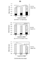
- FIG. 3 is a diagram showing a change characteristic of a ratio of copper loss and iron loss when the permanent magnet synchronous motor is driven at the same rotation speed and the torque and the temperature are changed.
- 3A is a calculation result by each magnetic field analysis at high torque, FIG. 3B at medium torque, and FIG. 3C at low torque.
- the output torque is the same even when the temperature changes.
- the current value is adjusted so that The numerical values in each figure are normalized by the loss under the temperature condition where the total of copper loss and iron loss is the largest under each condition. The resistance and the magnet temperature are assumed to change similarly.
- the torque command value of the permanent magnet synchronous motor having a higher temperature among the multiple permanent magnet synchronous motors is intentionally increased, and conversely, the torque command value of the permanent magnet synchronous motor having a low temperature is increased. It can be seen that the total can be driven with high efficiency by reducing
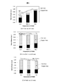
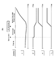
- FIG. 4 is a diagram showing a change characteristic of a ratio of copper loss and iron loss when the permanent magnet synchronous motor is driven with the same torque and the rotation speed and the temperature are changed.
- FIG. 4(a) is a calculation result by each magnetic field analysis at low speed rotation
- FIG. 4(b) is at medium speed rotation
- FIG. 4(c) is at high speed rotation. Adjust the current to be the same.
- the numerical values in each figure are normalized by the loss under the temperature condition where the total of copper loss and iron loss is the largest under each condition. The resistance and the magnet temperature are assumed to change similarly.
- the ratio of copper loss is relatively high due to the small iron loss under low rotation speed operating conditions. Further, when the temperature rises, the increase of the copper loss becomes larger than the decrease of the iron loss, and the lower the temperature of the permanent magnet synchronous motor becomes, the higher the efficiency becomes.
- the torque command value of the permanent magnet synchronous motor having a high temperature among the plurality of permanent magnet synchronous motors is intentionally increased, and conversely, the torque command value of the permanent magnet synchronous motor having a low temperature is increased. It can be seen that by reducing the amount, it is possible to drive with high efficiency as a whole.
- FIG. 5 shows an example of an operating region in which the permanent magnet synchronous motor has high efficiency when the temperature of the permanent magnet synchronous motor is higher or lower than the reference value with respect to speed (horizontal axis) and torque (vertical axis).
- the region in which the temperature becomes highly efficient has a boundary for torque and speed.
- the distribution of torque command values should be changed according to temperature, speed, and torque so that total efficiency is maximized. Efficiency can be improved.
- FIG. 6 is a diagram illustrating an example of functional blocks of the torque calculation unit 12 included in the overall control unit 1 illustrated in FIG. 1. Specifically, the torque command values ⁇ m1 * and ⁇ m2 * shown in FIG. 1 will be described with reference to FIG.
- the torque calculation unit 12 is configured by using the torque operation amount calculation unit 26, and obtains a map or efficiency showing the efficiency of the permanent magnet synchronous motor when the temperature changes. According to the calculation formula, the torque operation amount is added to the power command ⁇ m0 * and the torque command value is output.
- the above-mentioned map showing the efficiency or the calculation formula for obtaining the efficiency is derived by the actual measurement value or the magnetic field analysis, and a storage device (not shown) is appropriately provided in the integrated control unit 1 or the torque calculation unit 12. And record it.
- the torque operation amount calculation unit 26 determines a highly efficient permanent magnet synchronous motor based on the individual temperature estimated values of the permanent magnet synchronous motor, and determines the torque operation amount from the determination result.
- the calculation of the manipulated variables of the torque command values ⁇ m1 * to ⁇ m4 * and the compensation method thereof shown in FIG. 6 are merely examples, and the temperature dependency of the rotating electric machine is taken into consideration, and the calculation is performed according to the speed and frequency.
- the configuration is not limited to the configuration shown in FIG. 6 as long as the torque operation amount is individually adjusted. Further, in the first embodiment, an example in which the torque command value is operated has been shown, but a configuration in which a current command value and a voltage command value corresponding to the torque command value are operated may be adopted.
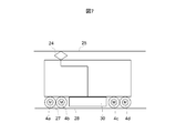
- FIG. 7 is a diagram showing a schematic configuration of a part of a railway vehicle equipped with a drive unit for a permanent magnet synchronous motor according to the present invention.
- a plurality of permanent magnet synchronous motors 4a, 4b, 4c and 4d driven by the inverter 30 are connected to the axles of the railway vehicle via reduction gears (not shown).
- the railway vehicle travels by the tangential force generated between the wheel 27 and the rail 28 connected to the axle.
- the center of gravity changes according to the traveling direction, so control that changes the torque distribution for each axis in the traveling direction is used, that the influence of traveling wind on the rotating electric machine is affected,
- the temperature varies among the rotating electric machines due to being affected by the fouling condition of the ventilation duct. Therefore, by applying the present invention to a railway vehicle, the effect of increasing the efficiency of the drive system of the railway vehicle can be obtained.
- the second embodiment differs from the first embodiment in that the temperature information of the permanent magnet synchronous motor uses the estimated magnet temperature at the time of zero torque control during driving in sensorless control.
- the temperature sensor shown in FIG. 2 is unnecessary, and the temperature of the permanent magnet can be robustly estimated against the constant error of the inductance and resistance of the permanent magnet synchronous motor.
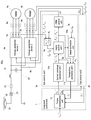
- FIG. 8 is a diagram illustrating an example of functional blocks of a drive device for a permanent magnet synchronous motor according to the second embodiment.
- the control unit 2a according to the second embodiment includes a PWM control unit 7a, a coordinate converter 8a, a current control unit 9a, a current command calculation unit 10a, a temperature estimation unit 11a, and a speed estimation unit 31a.
- the current command calculation unit 10a outputs the current command values I d1 * and I q1 * based on the torque command value ⁇ m1 * from the integrated control unit 1.
- the coordinate converter 8a converts the three-phase currents I u1 , I v1 and I w1 of the permanent magnet synchronous motor 3 detected by the current detector 5a into dq coordinates of the rotating coordinate system using the phase angle ⁇ 1 , and I It is output to the current controller 9a as d1 and I q1 .
- the current control unit 9a adjusts the current deviation by PI (Proportional-Integral) control or the like so that the d-axis current detection value I d1 and the q-axis current detection value I q1 match I d1 * and I q1 * .
- the voltage command values V d1 * and V q1 * are output so as to converge to zero.
- the PWM control unit 7a outputs a switching command SW 1 for controlling the voltage output device 3a based on the voltage command values V d1 * and V q1 * .
- the speed estimation unit 31a estimates the angular frequency ⁇ 1 * of the rotor based on the detected current values I d1 and I q1 and the voltage command values V d1 * and V q1 * .
- the temperature estimation unit 11a uses the current command values I d1 * and I q1 * or the current detection values I d1 and I q1 , the voltage command values V d1 * and V q1 *, and the angular frequency ⁇ 1 * based on the magnet.
- the temperature estimated value T 1 ⁇ or the magnet magnetic flux estimated value K e1 ⁇ is output.
- the magnet temperature and the magnet magnetic flux are calculated by converting ⁇ 0.1%/° C. with respect to the reference value, and either of them may be output as an estimated value.
- description will be made using the magnet magnetic flux estimated value K e1 ⁇ .
- the internal block diagram of the control unit 2b has the same configuration as that of the control unit 2a, and therefore the illustration thereof is omitted.
- the principle of estimating the temperature of the permanent magnet with high accuracy will be described below.
- the voltage equation of the permanent magnet synchronous motor is expressed by the following equations (3) and (4).
- the estimated value K e ⁇ of the magnetic flux can be calculated by the equation (5).
- the voltages v d and v q refer to the voltage command values v d * and v q * of the voltage output device 3, and the current is the current detection value i. d and i q may be used.
- the resistance r 1 and the inductors L d and L q depend on the winding temperature of the permanent magnet synchronous motor, the magnetic saturation characteristics of the magnetic material used for the iron core, the motor structure, and the current conditions, they are accurate. Difficult to grasp.
- the inventors intentionally set the current command values I d1 * and I q1 * of the d-axis and the q-axis to zero, and use the formula ( In the state where the torque shown in 2) is controlled to zero, by using the voltage command value V q * and the angular frequency ⁇ 1 * under stable control, the constant error of the resistance r 1 and the inductances L d and L q is obtained. It was found that the magnet magnetic flux K e can be estimated without being affected by
- the estimated value K e ⁇ of the magnetic flux of the magnet can be calculated by the following equation (8).
- the q-axis voltage command value V q * is a voltage that cancels the induced voltage due to the actual magnet magnetic flux K e. It is ready to output. Therefore, it is understood that the equation (7) does not include the terms of the resistance r 1 and the inductances L d and L q , and the voltage command value V q * can be calculated only by ⁇ 1 * and K e .
- the magnet magnetic flux K e can be estimated based on the q-axis voltage command value V q * when the current command values I d * and I q * are set to zero.
- the estimation method of the second embodiment cannot be applied in principle under the condition that the rotor speed ⁇ 1 of the permanent magnet synchronous motor is zero.
- the estimation of the magnet magnetic flux performed during this torque zero control period is performed by using the torque zero control period before the torque is started when the permanent magnet synchronous motor is restarted from the gate off and the rotor is free running (coasting). It is carried out, or it is carried out by using the torque zero control period immediately after the gate is turned off after the torque is lowered.
- FIG. 9 is a diagram showing a temporal flow of estimating the magnetic flux of the magnet during the torque zero control period before the torque rise at the coasting restart.
- FIG. 10 is a diagram showing a temporal flow for estimating the magnet magnetic flux in the torque zero control period immediately after the gate is turned off after the torque is lowered.
- a minute d-axis current may be flown without strictly setting the current to zero.
- the voltage output devices 3a and 3b a period in which the upper and lower output elements are turned off at the same time is provided in order to prevent a short circuit of elements such as IGBTs provided in the upper and lower arms provided for each phase.
- the output voltage in this simultaneous off period becomes insufficient. Therefore, by a known dead time compensation technique, compensation is added to the voltage command value so that the voltage according to the command value can be output based on the polarity of the current detection value or the current command value.
- the q-axis current command value is set to zero while the d-axis current command value is intentionally given a small value so that the polarity of the current command value or the current detection value can be determined.
- the polarity of the current can be discriminated, the dead time compensation can be operated accurately, and the voltage output accuracy can be improved.
- the magnitude of the small current command value I d is the magnetic flux due to armature reaction (L d and I d Of the magnetic flux K e is about 1/5 or less.
- the magnitude of the minute current command value I d * with respect to the set value (reference value) K e * of the power generation constant and the d-axis inductor L d * set in the controller may be set within the range of Expression (11).
- the temperature information can be obtained with high accuracy without using the temperature sensor. be able to.
- the torque operation amount allocation described in the first embodiment can be accurately distributed, and it is possible to further improve the efficiency and simplify the system as compared with the first embodiment.
- SYMBOLS 1 Basic control part, 2... Control part, 3... Voltage output device, 4... Permanent magnet synchronous motor, 5... Current detector, 6... AC contactor, 7... PWM control part, 8... Coordinate converter, 9... Current control unit, 10... Current command calculation unit, 11... Magnet temperature estimation unit, 12... Torque command calculation unit, 20... Filter capacitor, 21... Filter reactor, 22... Breaker, 23... High speed circuit breaker, 24... Panta, 25... Overhead wire, 26... Torque compensation calculation unit, 27... Wheels, 28... Rail, 30... Inverter, 31... Speed estimation calculation unit, 40... Temperature detector
Abstract
複数台の回転電機を駆動制御する際に、個々の回転電機の損失の温度依存性を考慮してトルク操作量を個々に変化させることで、複数台の回転電機により動力を得るシステムの効率を向上させるために、複数の回転電機に対して任意の電圧を出力する複数の電圧出力装置と、電圧出力装置の出力電圧を調整する制御装置とを備え、制御装置は、複数の回転電機個々の温度情報を取得し、個々の温度情報に基づいて複数の回転電機の中から相対的に高効率となる回転電機を選定し、選定した回転電機に対するトルク指令値を他の複数の回転電機に対して相対的に増加させる。
Description
本発明は、回転電機の駆動装置に関し、特に、鉄道車両用の永久磁石同期電動機の駆動装置として好適である。
近年、大規模輸送が可能でありエネルギー効率の高い、鉄道車両が注目されている。鉄道車両は、高効率な回転電機の導入、省エネ運転制御および回転電機の特性に合わせた制御によって、更なる省エネルギー化や効率の向上が期待されている。
これらの類の技術の一つとして、鉄道車両では、複数台の回転電機によって動力を得ることから、複数台の回転電機を個別に制御することで、鉄道車両用駆動システムの高効率化や信頼性を向上する技術が検討されている。
特許文献1には、鉄道車両の高効率化を目的に、電力変換装置と複数台の回転電機それぞれとの間に交流遮断器を設け、運転台からの運転制御指令に基づいて交流遮断器の開閉を個別に制御する遮断器制御部を備える構成を有し、車両の必要なトルクに応じて回転電機の駆動個数を少なくすることにより、回転電機が高効率となる動作条件で駆動する鉄道車両用制御装置が提案されている。
特許文献2には、開放運転時においても電気車の出力トルクを維持することを目的に、回転電機の温度が予め設定した許容値を超過した時または超過すると判断した時に、当該回転電機の温度を許容値内に抑制するトルク指令に変更するにあたり、他の回転電機のうち温度に余裕のある順にトルクを補完する回転電機を選定し、温度上昇が発生した回転電機における出力トルクの不足分を補う電気車制御装置が提案されている。
本願発明者は、鉄道車両用駆動装置の更なる効率の向上を目的に鋭意検討した結果、次の知見を得るに至った。
1)特許文献1では、遮断器を用いて回転電機の個数を切り替えて回転電機の効率が高くなる点で駆動させることにより、高効率化する技術が開示されている。そして、回転電機の温度変動に対しては駆動させる回転電機の温度が偏ることがないように、回転電機を選択して駆動しているが、単に温度の低い回転電機を動作させて複数の回転電機の損失を均等化するのみで、複数台の回転電機に発生する損失そのものは低減しておらず、高効率化には改善の余地がある。
また仮に、特許文献1に記載の技術を永久磁石同期電動機に適用した場合、回転子に永久磁石を備えるため、交流遮断器開放時の回転子のフリーラン中に鉄損が発生し、永久磁石同期電動機が温度上昇する問題がある。特に高速域では、通常の制御期間中は弱め界磁制御によって磁束を弱めるのに対し、開放時のフリーラン中は磁束を弱めないため鉄損が増加する。最高速付近では、通常の制御期間よりも開放期間の方が、発熱が増加する可能性があり、冷却性能や信頼性の点でも課題がある。
2)特許文献2では、開放運転時においても車両の出力トルクを維持することを目的に、回転電機の温度が予め設定した許容値を超過した時または超過すると判断した時に、温度に余裕のある回転電機の順に選定してトルクを補完する技術が開示されている。温度の超過時のみ動作するため、通常時においては高効率化の効果は得られないが、仮に、特許文献2の技術を適用し、温度に余裕のある順に回転電機のトルクを割り振った場合、低速回転時や高トルク時では、回転電機の損失の内、銅損が支配的な動作条件のため、温度が低い程、抵抗値が小さくなって高効率化の効果が得られる。
しかし、高速回転時や低トルク時では、鉄損が支配的な動作条件のため、温度が低い程、磁石磁束は増加し、効率が低下する問題が発生する。つまり、永久磁石同期電動機の温度に基づいて、温度に余裕のある順に回転電機のトルクを割り振るということだけでは高効率化には不十分であり、動作条件によっては効率の低下を招く可能性がある。
しかし、高速回転時や低トルク時では、鉄損が支配的な動作条件のため、温度が低い程、磁石磁束は増加し、効率が低下する問題が発生する。つまり、永久磁石同期電動機の温度に基づいて、温度に余裕のある順に回転電機のトルクを割り振るということだけでは高効率化には不十分であり、動作条件によっては効率の低下を招く可能性がある。
3)以上の理由により、複数台の回転電機、特に永久磁石同期電動機を用いた駆動システムの高効率化には改善の余地がある。
本発明の目的は、複数台の回転電機を駆動制御する際に、回転電機の温度依存性を考慮してトルク操作量を個々に変化させることで、複数台の回転電機によって動力を得るシステムの効率を向上させることである。
本発明は、複数の回転電機に対して任意の電圧を出力する複数の電圧出力装置と、電圧出力装置の出力電圧を調整する制御装置を備え、制御装置は、複数の回転電機個々の温度情報を取得し、個々の温度情報に基づいて複数の回転電機の中から相対的に高効率となる回転電機を選定し、選定した回転電機に対するトルク指令値を他の複数の回転電機に対して相対的に増加させることを特徴とする。
本発明によれば、複数台の回転電機を用いて駆動するシステムにおいて、回転電機の効率の温度依存性を考慮し、複数台の回転電機の出力トルクを個々に変化させることで、駆動システムの高効率化が図られ、更なる消費電力量の低減が可能となる。
以下、本発明を実施するための形態として、実施例1および2について、それぞれ図面に従い詳細に説明する。各実施例において参照番号が同一のものは、同一の構成要件または類似の機能を備えた構成要件として示している。
なお、以下に説明する構成は、あくまでも実施例として提示したものであり、本発明に係る実施態様は、以下の実施例に限定されるものではない。
なお、以下に説明する構成は、あくまでも実施例として提示したものであり、本発明に係る実施態様は、以下の実施例に限定されるものではない。
図1は、実施例1に係る永久磁石同期電動機の駆動装置の機能ブロックの一例を示す図である。永久磁石同期電動機の個々の温度情報に基づいて、複数の永久磁石同期電動機から成る駆動システムのトータル効率が高くなるように、トルク指令値を調整する際の構成を機能ブロックとして示したものである。
図1では、2台の永久磁石同期電動機4aおよび4bを示しているが、複数台であれば永久磁石同期電動機は2台に限定されるものではない。以下では、2台に対応させる形で、それぞれに関連する構成部品と機能を、添字aおよびbを用いて区別する。
また、図1では、パンタ24を介して架線25と電力の授受を行い、高速度遮断器23および断流器22によって、架線側と永久磁石同期電動機側の電流を遮断できる構成としている。また、電圧出力装置3aおよび3bと架線25との間には、フィルタリアクトル21とフィルタコンデンサ20とから成る直流電流平滑用のLCフィルタ回路を備える。
永久磁石同期電動機の駆動制御のための制御装置として、統括制御部1と制御部2aおよび2bとを含む。制御部2aおよび2bからのスイッチング指令に基づき、電圧出力装置3aおよび3bは電圧を出力し、永久磁石同期電動機4aおよび4bに所定のトルクを出力させて動力を得ている。
統括制御部1が備えるトルク演算部12は、上位のシステム制御部(図示は省略)からの動力指令τm0
*または制御モードの切替指令に応じて、永久磁石同期電動機4aおよび4bに発生させるトルク指令値τm1
*およびτm2
*を、制御部2aおよび2bそれぞれに出力する。
制御部2aおよび2bには、負荷として接続する永久磁石同期電動機4aおよび4bを駆動制御するための制御プログラムが実装されている。制御部2aおよび2bは、永久磁石同期電動機4aおよび4bが所定のトルクを出力するためのスイッチング指令SW1およびSW2を出力する。電圧出力装置3aおよび3bは、スイッチング指令SW1およびSW2を受けてスイッチング制御を行い、電圧を出力する。
ここで、図1は、実施例1に必要な最小限の機能ブロックのみを示したもので、IGBT(Insulated Gate Bipora Transistor)等の駆動用トランジスタやダイオード等のパワーデバイスから構成される電力変換器およびこの電力変換器に対する制御構成については、電圧出力装置3aおよび3bのブロック図で示し、詳細な図示を省略している。
永久磁石同期電動機4aおよび4bは、3相交流電圧の印加により固定子側に発生した回転磁界による磁極と回転子の永久磁石の磁極との吸引および反発によって発生するマグネットトルクと、固定子の回転磁界による磁極と回転子の磁気的な突極との吸引力によって発生するリラクタンストルクとにより、回転トルクを発生する。
電流検出器5aおよび5bは、永久磁石同期電動機4aおよび4bに流れるU相、V相およびW相の3相電流Iu1、Iv1およびIw1とIu2、Iv2およびIw2の波形をそれぞれ検出する。ただし、電流検出器5aおよび5bによって必ずしも3相全ての電流を検出する必要はなく、3相の内のいずれか2相を検出し、残る1相は3相電流が平衡状態であると仮定して演算により求める構成としてもよい。
また、交流接触器6aおよび6bは、電圧出力装置3aおよび3bと永久磁石同期電動機4aおよび4bとの間に設けられ、異常時に電流を遮断動作する。ここで、交流接触器6aおよび6bは、統括制御部1もしくは制御部2aおよび2bが出力する制御信号(図示は省略)に従い、開閉動作を行うものとする。
制御部2aおよび2bは、電流検出器5aおよび5bの電流検出値を用いて、永久磁石同期電動機4aおよび4bそれぞれの温度情報T1^およびT2^を推定し、統括制御部1に送信する。
また、実施例1の変形例として、図2に、永久磁石同期電動機4aおよび4bに温度検出器40aおよび40bを設置して、温度情報T1^およびT2^を検出する場合の構成を示す。温度検出に当たっては、フレーム温度、巻線温度または永久磁石温度等を検出する構成としてもよい。
以下に、本発明の要点となる永久磁石同期電動機の温度と効率との関係について説明する。
永久磁石同期電動機に発生する損失は、大きく分けて、銅損、機械損および鉄損に分類される。永久磁石同期電動機に対して、入力電力をPin、出力電力をPout、トルクをτm、銅損をWs、鉄損をWi、機械損をWmとし、回転電機の機械角の角周波数をωmとすると、永久磁石同期電動機の効率nは、式(1)で表される。

永久磁石同期電動機に発生する損失は、大きく分けて、銅損、機械損および鉄損に分類される。永久磁石同期電動機に対して、入力電力をPin、出力電力をPout、トルクをτm、銅損をWs、鉄損をWi、機械損をWmとし、回転電機の機械角の角周波数をωmとすると、永久磁石同期電動機の効率nは、式(1)で表される。
また、永久磁石同期電動機のトルクτmは、式(2)で表される。

ここで、mは相数、Pmは極対数、Keは磁石磁束(発電定数)、Idはd軸電流、Iqはq軸電流、Ldはd軸インダクタンス、Lqはq軸インダクタンスとする。
式(2)の第1項が、先のマグネットトルク(回転磁界による磁極と回転子の永久磁石の磁極との吸引および反発によって発生するトルク)であり、式(2)の第2項が、先のリラクタンストルク(固定子の回転磁界による磁極と回転子の磁気的な突極との吸引力によって発生するトルク)である。
マグネットトルクは、磁石磁束Keとq軸電流Iqの積によって決定することから、磁石磁束Keの変動の影響で変動し、出力トルクが増減することはよく知られている。永久磁石が、例えば-0.1%/℃で減磁すれば、温度が10℃上昇すると、磁石磁束Keは1%低下することとなる。すなわち、磁石磁束が増加する低温条件の方が、式(1)における分子の出力トルクが増加することから、高効率な動作になると考えられることが多い。
このような考え方に基づいて、駆動システムの高効率化を図る場合、例えば、高効率化を目的とする特許文献2に記載の技術を適用し、回転電機の温度に余裕のある順にトルクを補完することが考えられる。
しかし、発明者らは、詳細な検討に基づき、式(1)の分母が示す損失の温度依存性に着目して、単に温度の低い永久磁石同期電動機が高効率となるわけではなく、トルクと周波数の動作条件に応じて、温度の低い時と高い時のそれぞれで異なる動作領域において高効率になるということを見出した。
以下に、銅損Ws、機械損Wmおよび鉄損Wiの概要とそれらの温度依存性について説明する。
銅損Wsは、固定子巻線に発生する損失であり、永久磁石同期電動機に流れる電流値と抵抗値とから算出できる。銅損Wsの温度依存性については、抵抗値が固定子巻線に用いる材質の温度係数に従って変化するため、温度が高い程抵抗値は大きくなって銅損Wsは増加する傾向となる。
銅損Wsは、固定子巻線に発生する損失であり、永久磁石同期電動機に流れる電流値と抵抗値とから算出できる。銅損Wsの温度依存性については、抵抗値が固定子巻線に用いる材質の温度係数に従って変化するため、温度が高い程抵抗値は大きくなって銅損Wsは増加する傾向となる。
機械損Wmは、回転子に備える冷却ファンによる圧力損失や、回転子を永久磁石同期電動機のフレームに支持するベアリングの摩擦等によって発生するものであり、一般的には、駆動周波数の関数として算出できる。機械損Wmの温度依存性については、厳密にはベアリングに用いるグリースの粘度の変化等があるものの、鉄道車両用回転電機では無視できる程の変化である。そのため、鉄道車両用回転電機の機械損Wmは、温度による影響を受けないものとして扱われることが多い。
鉄損Wiは、交流磁界を印加して固定子鉄心や回転子鉄心に用いる磁性材料中の磁束が変化した際のヒステリシスループの面積に応じた磁気損失であり、ヒステリシス損と渦電流損との和として定義され、一般的には磁束密度と周波数との関数として算出できる。鉄損Wiの温度依存性については、永久磁石同期電動機で鉄損に大きく影響する磁石磁束そのものが温度依存性を持ち、温度上昇時には、上述のように例えば-0.1%/℃程度で減磁する。
さらに、鉄損Wiの内、ヒステリシス損は、温度依存性がほぼ無いと考えられる場合が多い。しかし、渦電流損は、温度上昇により鉄心の電気抵抗が増加すると、その損失は低減する傾向にある。そのため、永久磁石同期電動機における鉄損Wiは、温度が高い程減少する傾向となる。
以上のとおり、永久磁石同期電動機の損失は、温度の低い時では、銅損が低減して鉄損は増加し、逆に、温度の高い時では、銅損が増加して鉄損は減少する。すなわち、銅損と鉄損とは、温度に対してトレードオフの関係となるため、ある動作条件での温度変化時における損失の変化を考えた場合、鉄損と銅損との割合によって、低温と高温のどちらの条件で回転電機としての損失が小さくなるかが異なることとなる。
図3は、永久磁石同期電動機を同一の回転速度で駆動し、トルクと温度とを変化させた時の銅損と鉄損との割合の変化特性を示す図である。
図3の(a)は高トルク時、図3の(b)は中トルク時、図3の(c)は低トルク時の各磁界解析による計算結果で、温度変化時においても出力トルクは同一となるように電流値を調整している。また、各図の数値は、各条件で銅損と鉄損との合計が最も大きくなる温度条件の損失で正規化している。なお、抵抗と磁石温度とは、同様に変化することを仮定している。
図3の(a)は高トルク時、図3の(b)は中トルク時、図3の(c)は低トルク時の各磁界解析による計算結果で、温度変化時においても出力トルクは同一となるように電流値を調整している。また、各図の数値は、各条件で銅損と鉄損との合計が最も大きくなる温度条件の損失で正規化している。なお、抵抗と磁石温度とは、同様に変化することを仮定している。
高トルク時は、図3の(a)のように、トルクが大きい動作条件では大電流を流すため、図3の(b)および(c)に対して銅損の割合が大きくなる。また、温度上昇時には、鉄損の減少よりも銅損の増加の方が大きくなり、永久磁石同期電動機の温度が低い方が高効率となる。
中トルク時は、図3の(b)のように、図3の(a)よりも負荷トルクが小さく電流も小さくなる条件であるため、回転電機の温度の高い方がわずかに効率は良くなる。
低トルク時は、トルクがほぼゼロの動作条件であり、このような条件下では、図3の(c)のように、高温時の方が、低温時に対して銅損と鉄損との合計を3割近く低減することを可能にする。
すなわち、負荷トルクが小さい動作条件では、複数台の永久磁石同期電動機の内、温度の高い永久磁石同期電動機のトルク指令値を敢えて増加させ、逆に、温度の低い永久磁石同期電動機のトルク指令値を低減することにより、トータルとして高効率で駆動できることが分かる。
図4は、永久磁石同期電動機を同一のトルクで駆動し、回転速度と温度とを変化させた時の銅損と鉄損との割合の変化特性を示す図である。
図4の(a)は低速回転時、図4の(b)は中速回転時、図4の(c)は高速回転時の各磁界解析による計算結果で、温度変化時においても、出力トルクは同一となるように電流を調整している。また、各図の数値は、各条件で銅損と鉄損との合計が最も大きくなる温度条件の損失で正規化している。なお、抵抗と磁石温度とは、同様に変化することを仮定している。
図4の(a)は低速回転時、図4の(b)は中速回転時、図4の(c)は高速回転時の各磁界解析による計算結果で、温度変化時においても、出力トルクは同一となるように電流を調整している。また、各図の数値は、各条件で銅損と鉄損との合計が最も大きくなる温度条件の損失で正規化している。なお、抵抗と磁石温度とは、同様に変化することを仮定している。
低速回転時は、図4の(a)のように、回転速度の低い動作条件では、鉄損が小さいため相対的に銅損の割合が高くなる。また、温度上昇時には、鉄損の低減よりも銅損の増加の方が大きくなり、永久磁石同期電動機の温度が低い方が高効率となる。
中速回転時は、図4の(b)のように、図4の(a)よりも回転速度が高く鉄損の割合が相対的に大きくなる条件であるため、回転電機の温度が変わっても効率がほぼ変化しない領域となる。
高速回転時は、図4の(b)よりもさらに回転速度が高く、このような条件下では、図4の(c)のように、高温時の方が、低温時に対して銅損と鉄損との合計を1割近く低減することを可能にする。
すなわち、回転速度が高い条件では、複数台の永久磁石同期電動機の内、温度の高い永久磁石同期電動機のトルク指令値を敢えて増加させ、逆に、温度の低い永久磁石同期電動機のトルク指令値を低減することにより、トータルとして高効率で駆動できることが分かる。
図5は、速度(横軸)とトルク(縦軸)に対して、永久磁石同期電動機の温度が基準値よりも高い場合と低い場合で、永久磁石同期電動機が高効率となる動作領域の一例を示す図である。
図3および図4に示したように、温度の仕様範囲の中央値を基準にした場合、温度によって高効率となる領域は、トルクと速度に対して境界を持つこととなる。つまり、少なくとも2台以上の永久磁石同期電動機で動力を得る場合には、温度、速度およびトルクに応じて、トータルの効率が最大となるようにトルク指令値の配分を変更すれば、システムの高効率化が可能となる。
ここで、図6は、図1に示す統括制御部1が備えるトルク演算部12の機能ブロックの一例を示す図である。
具体的に、図1に示すトルク指令値τm1 *およびτm2 *について、図6を用いて説明する。トルク演算部12は、図6の(b)および(c)に示すように、トルク操作量演算部26を用いて構成され、永久磁石同期電動機の温度変化時における効率を示すマップまたは効率を求める算出式に従って、動力指令τm0 *に対してトルク操作量を加算してトルク指令値を出力する。上記の効率を示すマップまたは効率を求める算出式は、実測値や磁界解析によって導いたものであって、統括制御部1またはトルク演算部12の中に適宜に記憶装置(図示は省略)を設けて記録しておく。
具体的に、図1に示すトルク指令値τm1 *およびτm2 *について、図6を用いて説明する。トルク演算部12は、図6の(b)および(c)に示すように、トルク操作量演算部26を用いて構成され、永久磁石同期電動機の温度変化時における効率を示すマップまたは効率を求める算出式に従って、動力指令τm0 *に対してトルク操作量を加算してトルク指令値を出力する。上記の効率を示すマップまたは効率を求める算出式は、実測値や磁界解析によって導いたものであって、統括制御部1またはトルク演算部12の中に適宜に記憶装置(図示は省略)を設けて記録しておく。
例えば、2モータ単位に適用する場合には、(b)に示すように、Δτm1
*およびΔτm2
*を動力指令τm0
*に加算してトルク指令値τm1
*およびτm2
*を算出する。
また、4モータ単位に適用する場合には、(c)に示すように、Δτm1 *、Δτm2 *、Δτm3 *およびΔτm4 *を動力指令τm0 *に加算してトルク指令値τm1 *、τm2 *、τm3 *およびτm4 *を算出する。
また、4モータ単位に適用する場合には、(c)に示すように、Δτm1 *、Δτm2 *、Δτm3 *およびΔτm4 *を動力指令τm0 *に加算してトルク指令値τm1 *、τm2 *、τm3 *およびτm4 *を算出する。
トルク操作量演算部26は、永久磁石同期電動機の個々の温度推定値に基づき、高効率となる永久磁石同期電動機を判別し、判別結果からトルク操作量を決定する。ただし、図6の(a)に示す従来の構成に対し、駆動システムから出力されるトルクの総量を変化させないために、図6の(b)または(c)に示すように、トルク補償量の和は略ゼロ(Δτm1
*+Δτm2
*=0またはΔτm1
*+Δτm2
*+Δτm3
*+Δτm4
*=0)となるように、換言すれば、駆動システムにおけるトルク指令値の総量は略一定となるように、調整する。
ここにおいて、図6に示すトルク指令値Δτm1
*~Δτm4
*の操作量の演算やその補償法は、あくまでも一例であって、回転電機の温度依存性を考慮し、速度や周波数に応じてトルク操作量を個々に調整する構成であれば、図6に示す構成に限定されるものではない。
また、実施例1では、トルク指令値を操作する例を示したが、トルク指令値に相当する電流指令値や電圧指令値を操作する構成としてもよい。
また、実施例1では、トルク指令値を操作する例を示したが、トルク指令値に相当する電流指令値や電圧指令値を操作する構成としてもよい。
ただし、低トルク時や高速回転時に、温度の高い回転電機を積極的に使用することで温度上昇が懸念される。しかし、鉄道車両では、同一の周波数やトルクの動作点で常時運転をし続けることはなく、停止、加速、減速および停止の動作を繰り返すため、高温の回転電機のみに偏って駆動することはないので、異常な発熱等は発生しない。ただし、永久磁石の不可逆減磁等を考慮した温度許容値を超えることが予測される場合には、温度の高い回転電機のトルク指令値を増加させず、温度に対するリミッタを設けて補償を停止させるようにする。
他方、回転電機として誘導電動機を用いた駆動システムの場合は、回転電機として永久磁石を用いていないため、温度上昇時に磁束が減少することはない。そのため、鉄損(回転子に発生する二次銅損を除いた磁気損失)は温度によらず略一定となる。つまり、誘導電動機の場合は、単に温度の低い回転電機(誘導電動機)に対してトルク指令の配分を大きくすることで、駆動システムのトータル効率の向上が可能となる。
図7は、本発明に係る永久磁石同期電動機の駆動装置を搭載する鉄道車両の一部の概略構成を示す図である。インバータ30によって駆動する複数の永久磁石同期電動機4a、4b、4cおよび4dが、減速ギア(図示は省略)を介して鉄道車両の車軸と連結されている。鉄道車両は、車軸に接続された車輪27とレール28との間に生じる接線力により走行する。
鉄道車両では、進行方向に応じて重心が変わることから進行方向に対して軸毎にトルクの配分を変更させる制御を用いること、回転電機への走行風の当たり方の影響を受けること、回転電機の通風ダクトの汚損状態の影響を受けること、等が起因して、回転電機毎に温度がばらつく。そのため、本発明を鉄道車両に適用することで、鉄道車両の駆動システムを高効率化する効果が得られる。
以上のとおり、実施例1では、個々の永久磁石同期電動機の温度依存性を考慮してトルク操作量を個々に変化させることで、複数台の永久磁石同期電動機のトータル効率を向上させることが可能となる。
実施例2は、実施例1と比べて、永久磁石同期電動機の温度情報として、センサレス制御で駆動中のトルクゼロ制御時における推定磁石温度を用いる点で異なる。これにより、図2に示す温度センサを不要とし、かつ、永久磁石同期電動機のインダクタンスや抵抗の定数誤差に対して、ロバストに永久磁石の温度を推定することができる。
図8は、実施例2に係る永久磁石同期電動機の駆動装置の機能ブロックの一例を示す図である。
実施例2の制御部2aは、PWM制御部7a、座標変換器8a、電流制御部9a、電流指令演算部10a、温度推定部11aおよび速度推定部31aを内部に備える。
実施例2の制御部2aは、PWM制御部7a、座標変換器8a、電流制御部9a、電流指令演算部10a、温度推定部11aおよび速度推定部31aを内部に備える。
電流指令演算部10aは、統括制御部1からのトルク指令値τm1
*に基づき、電流指令値Id1
*およびIq1
*を出力する。
座標変換器8aは、電流検出器5aで検出した永久磁石同期電動機3の3相電流Iu1、Iv1およびIw1を、位相角θ1を用いて回転座標系のdq座標に変換し、Id1およびIq1として電流制御部9aに出力する。
電流制御部9aは、Id1
*およびIq1
*に対して、d軸電流検出値Id1およびq軸電流検出値Iq1が一致するように、PI(Proportional-Integral)制御等により電流偏差をゼロに収束させるように、電圧指令値Vd1
*およびVq1
*を出力する。
PWM制御部7aは、電圧指令値Vd1
*およびVq1
*に基づき、電圧出力装置3aを制御するためのスイッチング指令SW1を出力する。
速度推定部31aは、電流検出値Id1およびIq1と電圧指令値Vd1
*およびVq1
*とに基づき、回転子の角周波数ω1
*を推定する。
温度推定部11aは、電流指令値Id1
*およびIq1
*または電流検出値Id1およびIq1と、電圧指令値Vd1
*およびVq1
*と、角周波数ω1
*とに基づいて、磁石温度推定値T1^または磁石磁束推定値Ke1^を出力する。磁石温度および磁石磁束は、基準値に対して-0.1%/℃の換算で算出するものとし、どちらを推定値として出力する構成としてもよい。以降では、磁石磁束推定値Ke1^を用いて説明する。
また、制御部2bの内部のブロック図は、制御部2aと同一構成であるので、図示を省略する。
また、制御部2bの内部のブロック図は、制御部2aと同一構成であるので、図示を省略する。
以下に、永久磁石の温度を高精度に推定する原理について説明する。永久磁石同期電動機の電圧方程式は次式(3)および(4)で表される。


仮に、永久磁石同期電動機の実際の電圧、電流、抵抗値およびインダクタンスの各状態量を正確に把握できるとすれば、式(5)にて磁束の推定値Ke^を算定できる。

式(5)により磁石磁束の定数Ke^の算定を考えると、電圧vdおよびvqは電圧出力装置3の電圧指令値vd
*およびvq
*を参照し、電流は電流検出値idおよびiqを用いればよい。ところが、抵抗r1とインダクンタスLdおよびLqは、永久磁石同期電動機の巻線温度や、鉄心に用いられる磁性材料の磁気飽和特性、モータ構造および電流条件に依存するものであることから、正確に把握することが難しい。
そこで、発明者らは、定数誤差の影響を受けずに磁石磁束Keを推定するために、d軸およびq軸の電流指令値Id1
*およびIq1
*を意図的にゼロとして、式(2)に示すトルクをゼロに制御した状態において、制御が安定した状態での電圧指令値Vq
*および角周波数ω1
*を用いることで、抵抗r1およびインダクタンスLd並びにLqの定数誤差の影響を受けることなく磁石磁束Keを推定できることを見出した。
式(2)および(3)で、電流指令値Id
*およびIq
*をゼロに設定し、電流制御部10による電流制御の誤差をゼロと見なすと、整定した状態の電圧指令値Vd
*およびVq
*は、次式(6)および(7)となる。


すなわち、磁石磁束の推定値Ke^は、次式(8)にて算出できる。

電流指令値Id
*およびIq
*をゼロにして、電流制御による誤差がゼロとすると、q軸の電圧指令値Vq
*は、実際の磁石磁束Keによる誘起電圧を打ち消すだけの電圧を出力する状態となる。よって、式(7)は、抵抗r1およびインダクンタスLd並びにLqの項を含まず、電圧指令値Vq
*はω1
*とKeのみによって算定できることが分かる。
また、同一の周波数において磁石磁束が変動した場合を例にすると、式(7)から、永久磁石の温度が上昇して実際の磁石磁束Keが減少した場合には、整定した状態のVq
*も減少する。逆に、永久磁石の温度が低下して実際の磁束Keが増加した場合には、整定した状態のVq
*も増加する。このようにして、電流指令値Id
*およびIq
*をゼロとした際のq軸電圧指令値Vq
*に基づき、磁石磁束Keを推定することが可能となる。ただし、式(8)から、永久磁石同期電動機の回転子速度ω1がゼロの条件では、実施例2の推定法は原理的に適用できない。
ここで、実施例2の推定法では、電流制御による電流偏差がゼロとなっている必要があるため、電流指令値Id
*およびIq
*をゼロとして駆動制御し、制御が整定した状態でのq軸電圧指令値Vq
*および角周波数指令値ω1
*を用いる。また、ノイズの影響を除去するために、フィルタ処理、移動平均処理または積分処理を施してもよい。
次に、このトルクゼロ制御期間に実施する磁石磁束の推定は、ゲートオフかつ回転子がフリーラン(惰行)中から、永久磁石同期電動機を再起動する際のトルク立上げ前のトルクゼロ制御期間を用いて実施するか、または、トルク立下げ後のゲートオフ直前のトルクゼロ制御期間を用いて実施する。
図9は、惰行再起動時のトルク立上げ前のトルクゼロ制御期間に磁石磁束の推定を実施する時間的流れを示す図である。また、図10は、トルク立下げ後のゲートオフ直前のトルクゼロ制御期間に磁石磁束の推定を実施する時間的流れを示す図である。
ただし、トルクゼロ指令時において、電流を厳密にゼロとせずに、微小なd軸電流を流す構成としてもよい。電圧出力装置3aおよび3bでは、各相に設けられた上下アームに備えたIGBT等の素子の短絡防止のために、上下の出力素子を同時にオフする期間を設けるため、電圧補償を加えない場合は、この同時オフ期間の出力電圧が不足することとなる。そこで、公知として知られるデッドタイム補償技術により、電流検出値または電流指令値の極性に基づき、指令値通りの電圧を出力できるように、電圧指令値に補償を加える。
特に、永久磁石同期電動機の誘起電圧が低くかつ変調率の低い低速域では、細い幅の電圧パルスを数多く出力する状態となるため、出力電圧に対して相対的にこの同時オフ期間が占める割合が大きくなり、出力電圧に与える影響が大きくなり易い。
すなわち、低速域において、実施例1に示したd軸電流指令値Id *とq軸電流指令値Iq *の両者をゼロにした場合、上述のとおり、デッドタイム補償に用いる電流検出値または電流指令値の極性が正確に把握できず、誤った極性に基づき電圧補償したとなれば、デッドタイム補償によって逆に電圧誤差を増加させることになり、推定精度を低下させる可能性がある。
すなわち、低速域において、実施例1に示したd軸電流指令値Id *とq軸電流指令値Iq *の両者をゼロにした場合、上述のとおり、デッドタイム補償に用いる電流検出値または電流指令値の極性が正確に把握できず、誤った極性に基づき電圧補償したとなれば、デッドタイム補償によって逆に電圧誤差を増加させることになり、推定精度を低下させる可能性がある。
これに対し、電流指令値または電流検出値の極性を判断できるように、q軸電流指令値はゼロとしつつ、d軸電流指令値には意図的に微小な値を与える。これにより、トルクゼロ指令時においても、電流の極性の判別が可能となり、デッドタイム補償を正確に動作させることができ、電圧出力精度を向上させることができる。
ただし、式(10)に示すように、d軸インダクンタスLdの定数誤差の影響を受けないように、微小な電流指令値Idの大きさは、電機子反作用による磁束(LdとIdの積)が、磁石磁束Keに対して1/5程度以下になるようにする。例えば、1/5以下にする場合、制御器に設定している発電定数の設定値(基準値)Ke
*とd軸インダクンタスLd
*に対して、微小な電流指令値Id
*の大きさは、式(11)の範囲にすればよい。


以上のとおり、実施例2では、センサレス制御でのトルク指令値をゼロに制御した期間に磁石温度(または磁石磁束)を算出することで、温度センサを用いることなく、高精度に温度情報を得ることができる。また、実施例2は、実施例1に記載のトルク操作量の割り振りを正確に配分でき、実施例1よりも更なる高効率化およびシステムの簡素化が可能となる。
1…統括制御部、2…制御部、3…電圧出力装置、4…永久磁石同期電動機、5…電流検出器、6…交流接触器、7…PWM制御部、8…座標変換器、9…電流制御部、10…電流指令演算部、11…磁石温度推定部、12…トルク指令演算部、20…フィルタコンデンサ、21…フィルタリアクトル、22…断流器、23…高速度遮断器、24…パンタ、25…架線、26…トルク補償演算部、27…車輪、28…レール、30…インバータ、31…速度推定演算部、40…温度検出器
Claims (19)
- 複数の回転電機に対して任意の電圧を出力する複数の電圧出力装置と、
前記電圧出力装置の出力電圧を調整する制御装置と
を備え、
前記制御装置は、
前記複数の回転電機個々の温度を取得し、
前記個々の温度に基づいて前記複数の回転電機の中から相対的に高効率となる回転電機を選定し、
選定した前記回転電機に対するトルク指令値を他の前記複数の回転電機に対して相対的に増加させる
ことを特徴とする回転電機の駆動装置。 - 請求項1に記載の回転電機の駆動装置であって、
前記複数の回転電機に対するトルク指令値の総量は略一定となる
ことを特徴とする回転電機の駆動装置。 - 請求項1または2に記載の回転電機の駆動装置であって、
前記回転電機は永久磁石同期電動機である
ことを特徴とする回転電機の駆動装置。 - 請求項3に記載の回転電機の駆動装置であって、
前記制御装置は、
低速域では前記温度が複数の前記永久磁石同期電動機の中で相対的に低い電動機を選定し、
高速域では前記温度が複数の前記永久磁石同期電動機の中で相対的に高い電動機を選定する
ことを特徴とする回転電機の駆動装置。 - 請求項3に記載の回転電機の駆動装置であって、
前記制御装置は、
前記トルク指令値が大きい場合は前記温度が複数の前記永久磁石同期電動機の中で相対的に低い電動機を選定し、
前記トルク指令値が小さい場合は前記温度が複数の前記永久磁石同期電動機の中で相対的に高い電動機を選定する
ことを特徴とする回転電機の駆動装置。 - 請求項3から5のいずれか1項に記載の回転電機の駆動装置であって、
前記制御装置は、
前記永久磁石同期電動機の温度変化時における当該永久磁石同期電動機の効率を示すマップまたは当該効率を求める演算式を記録しておき、
前記マップまたは前記演算式に基づき、前記永久磁石同期電動機の温度変化に対して複数の前記永久磁石同期電動機の中から相対的に高効率となる電動機を選定する
ことを特徴とする回転電機の駆動装置。 - 請求項3から6のいずれか1項に記載の回転電機の駆動装置であって、
前記制御装置は、前記永久磁石同期電動機の高速域または低トルク域で、前記温度が予め設定した許容温度を超えた場合に、当該温度の高い当該永久磁石同期電動機に対する前記トルク指令値を増加させない
ことを特徴とする回転電機の駆動装置。 - 請求項3から7のいずれか1項に記載の回転電機の駆動装置であって、
前記温度として、前記永久磁石同期電動機の回転子中の永久磁石の温度推定値を用いる
ことを特徴とする回転電機の駆動装置。 - 請求項8に記載の回転電機の駆動装置であって、
前記制御装置は、前記温度または前記永久磁石の磁束量を、前記永久磁石同期電動機に対する前記トルク指令値を略ゼロにして駆動する期間を利用して推定する
ことを特徴とする回転電機の駆動装置。 - 請求項9に記載の回転電機の駆動装置であって、
前記回転子中の永久磁石が形成する磁極の方向をd軸、当該d軸に対して電気角で直行する方向をq軸、前記制御装置での前記d軸におけるインダクタンスの設定値および前記磁石磁束の設定値をそれぞれLd *およびKe *並びに前記d軸の電流指令値をid *とした場合に、
前記トルク指令値が略ゼロとは、前記q軸の電流指令値がゼロで、かつ前記d軸の電流指令値id *が
である
ことを特徴とする回転電機の駆動装置。 - 請求項9または10に記載の回転電機の駆動装置であって、
前記制御装置は、前記永久磁石同期電動機に対する電圧出力が停止されかつ当該永久磁石同期電動機の回転子がフリーランの状態からの惰行再起動時において、前記トルク指令値を立ち上げる前に設けた当該トルク指令値をゼロにする期間に前記温度または前記磁束量を推定する
ことを特徴とする回転電機の駆動装置。 - 請求項9から11のいずれか1項に記載の回転電機の駆動装置であって、
前記制御装置は、前記トルク指令値をゼロに絞った後で前記永久磁石同期電動機の回転子速度が所定値以上である場合において、前記トルク指令値をゼロとして駆動する期間に前記温度または前記磁束量を推定する
ことを特徴とする回転電機の駆動装置。 - 請求項1または2に記載の回転電機の駆動装置であって、
前記回転電機は誘導電動機である
ことを特徴とする回転電機の駆動装置。 - 請求項13に記載の回転電機の駆動装置であって、
前記制御装置は、前記温度の低い前記誘導電動機に対する前記トルク指令値を他の前記誘導電動機に対して相対的に増加させる
ことを特徴とする回転電機の駆動装置。 - 請求項1から14のいずれか1項に記載の回転電機の駆動装置を搭載し当該回転電機は車輪を駆動する電動機である鉄道車両。
- 任意の電圧を出力する複数の電圧出力装置によって駆動される複数の回転電機個々の温度情報を取得し、
前記個々の温度情報に基づいて前記複数の回転電機の中から相対的に高効率となる回転電機を選定し、
選定した前記回転電機に対するトルク指令値を他の前記複数の回転電機に対して相対的に増加させる
ことを特徴とする回転電機の駆動方法。 - 請求項16に記載の回転電機の駆動方法であって、
前記複数の回転電機に対するトルク指令値の総量を略一定とする
ことを特徴とする回転電機の駆動方法。 - 請求項16または17に記載の回転電機の駆動方法であって、
前記回転電機は永久磁石同期電動機であり、
低速域では前記温度情報の値が複数の前記永久磁石同期電動機の中で相対的に低い電動機を選定し、高速域では前記温度情報の値が複数の前記永久磁石同期電動機の中で相対的に高い電動機を選定する
ことを特徴とする回転電機の駆動方法。 - 請求項16または17に記載の回転電機の駆動方法であって、
前記回転電機は永久磁石同期電動機であり、
前記トルク指令値が大きい場合は前記温度情報の値が複数の前記永久磁石同期電動機の中で相対的に低い電動機を選定し、前記トルク指令値が小さい場合は前記温度情報の値が複数の前記永久磁石同期電動機の中で相対的に高い電動機を選定する
ことを特徴とする回転電機の駆動方法。
Priority Applications (3)
| Application Number | Priority Date | Filing Date | Title |
|---|---|---|---|
| JP2020562907A JP7181946B2 (ja) | 2018-12-28 | 2019-11-13 | 回転電機の駆動装置および駆動方法 |
| CN201980083421.6A CN113196642A (zh) | 2018-12-28 | 2019-11-13 | 旋转电机的驱动装置以及驱动方法 |
| EP19906074.0A EP3905511A4 (en) | 2018-12-28 | 2019-11-13 | DRIVING DEVICE FOR A DYNAMOELECTRIC MACHINE AND METHOD OF DRIVING |
Applications Claiming Priority (2)
| Application Number | Priority Date | Filing Date | Title |
|---|---|---|---|
| JP2018247828 | 2018-12-28 | ||
| JP2018-247828 | 2018-12-28 |
Publications (1)
| Publication Number | Publication Date |
|---|---|
| WO2020137219A1 true WO2020137219A1 (ja) | 2020-07-02 |
Family
ID=71126551
Family Applications (1)
| Application Number | Title | Priority Date | Filing Date |
|---|---|---|---|
| PCT/JP2019/044581 WO2020137219A1 (ja) | 2018-12-28 | 2019-11-13 | 回転電機の駆動装置および駆動方法 |
Country Status (4)
| Country | Link |
|---|---|
| EP (1) | EP3905511A4 (ja) |
| JP (1) | JP7181946B2 (ja) |
| CN (1) | CN113196642A (ja) |
| WO (1) | WO2020137219A1 (ja) |
Cited By (3)
| Publication number | Priority date | Publication date | Assignee | Title |
|---|---|---|---|---|
| CN113400953A (zh) * | 2021-07-30 | 2021-09-17 | 精进电动科技股份有限公司 | 一种双电机转矩分配方法及双电机系统 |
| WO2022085543A1 (ja) * | 2020-10-20 | 2022-04-28 | ファナック株式会社 | 電動機のモデルのパラメータを設定するパラメータ設定装置 |
| WO2022085545A1 (ja) * | 2020-10-20 | 2022-04-28 | ファナック株式会社 | 電動機の温度検出器の温度を推定する温度推定装置 |
Citations (14)
| Publication number | Priority date | Publication date | Assignee | Title |
|---|---|---|---|---|
| JPH0538182A (ja) * | 1991-07-24 | 1993-02-12 | Hitachi Ltd | エレベーター装置 |
| JPH0739018A (ja) * | 1993-07-16 | 1995-02-07 | Nissan Motor Co Ltd | 電動車両の動力制御装置 |
| JPH07131994A (ja) * | 1993-10-29 | 1995-05-19 | Nissan Motor Co Ltd | 複数モータの駆動制御装置 |
| JPH1169871A (ja) * | 1997-08-14 | 1999-03-09 | Oki Electric Ind Co Ltd | モータ制御装置および自動機器 |
| JP2004201425A (ja) * | 2002-07-25 | 2004-07-15 | Daikin Ind Ltd | モータ温度推定装置及び圧縮機内部状態推定装置 |
| JP2010130726A (ja) * | 2008-11-25 | 2010-06-10 | Toyota Motor Corp | 交流電動機の制御装置 |
| JP5060266B2 (ja) | 2007-12-14 | 2012-10-31 | 株式会社東芝 | 電気車制御装置 |
| JP2013165641A (ja) * | 2013-03-21 | 2013-08-22 | Daikin Ind Ltd | 冷凍装置の電力制御基板 |
| JP2013198340A (ja) * | 2012-03-22 | 2013-09-30 | Mitsubishi Electric Corp | 同期機制御装置 |
| WO2014057575A1 (ja) * | 2012-10-12 | 2014-04-17 | 三菱電機株式会社 | 同期機制御装置 |
| JP2015035874A (ja) * | 2013-08-08 | 2015-02-19 | トヨタ自動車株式会社 | 電力制御装置 |
| JP2017011872A (ja) * | 2015-06-22 | 2017-01-12 | 株式会社神戸製鋼所 | 電動システムの駆動制御装置 |
| JP2018057185A (ja) | 2016-09-29 | 2018-04-05 | 株式会社日立製作所 | 鉄道車両用制御装置 |
| JP2018137932A (ja) * | 2017-02-23 | 2018-08-30 | コニカミノルタ株式会社 | 電動機制御装置、制御方法、および画像形成装置 |
Family Cites Families (6)
| Publication number | Priority date | Publication date | Assignee | Title |
|---|---|---|---|---|
| AU586358B2 (en) * | 1986-10-08 | 1989-07-06 | Hitachi Limited | A control apparatus for an induction motor |
| JPH1118496A (ja) * | 1997-06-18 | 1999-01-22 | Hitachi Ltd | 電気車の制御装置および制御方法 |
| JP2006297506A (ja) * | 2005-04-18 | 2006-11-02 | Amada Co Ltd | パンチプレス用タッピング装置及びパンチプレス用タッピング加工制御方法 |
| US7979171B2 (en) * | 2010-09-21 | 2011-07-12 | Ford Global Technologies, Llc | Permanent magnet temperature estimation |
| JP2014024442A (ja) * | 2012-07-26 | 2014-02-06 | Toyota Motor Corp | ハイブリッド車両用動力装置の制御装置 |
| JP2014068443A (ja) * | 2012-09-25 | 2014-04-17 | Hitachi Automotive Systems Ltd | 回転電機の駆動制御装置および電動車両駆動システム |
-
2019
- 2019-11-13 WO PCT/JP2019/044581 patent/WO2020137219A1/ja unknown
- 2019-11-13 EP EP19906074.0A patent/EP3905511A4/en active Pending
- 2019-11-13 JP JP2020562907A patent/JP7181946B2/ja active Active
- 2019-11-13 CN CN201980083421.6A patent/CN113196642A/zh active Pending
Patent Citations (14)
| Publication number | Priority date | Publication date | Assignee | Title |
|---|---|---|---|---|
| JPH0538182A (ja) * | 1991-07-24 | 1993-02-12 | Hitachi Ltd | エレベーター装置 |
| JPH0739018A (ja) * | 1993-07-16 | 1995-02-07 | Nissan Motor Co Ltd | 電動車両の動力制御装置 |
| JPH07131994A (ja) * | 1993-10-29 | 1995-05-19 | Nissan Motor Co Ltd | 複数モータの駆動制御装置 |
| JPH1169871A (ja) * | 1997-08-14 | 1999-03-09 | Oki Electric Ind Co Ltd | モータ制御装置および自動機器 |
| JP2004201425A (ja) * | 2002-07-25 | 2004-07-15 | Daikin Ind Ltd | モータ温度推定装置及び圧縮機内部状態推定装置 |
| JP5060266B2 (ja) | 2007-12-14 | 2012-10-31 | 株式会社東芝 | 電気車制御装置 |
| JP2010130726A (ja) * | 2008-11-25 | 2010-06-10 | Toyota Motor Corp | 交流電動機の制御装置 |
| JP2013198340A (ja) * | 2012-03-22 | 2013-09-30 | Mitsubishi Electric Corp | 同期機制御装置 |
| WO2014057575A1 (ja) * | 2012-10-12 | 2014-04-17 | 三菱電機株式会社 | 同期機制御装置 |
| JP2013165641A (ja) * | 2013-03-21 | 2013-08-22 | Daikin Ind Ltd | 冷凍装置の電力制御基板 |
| JP2015035874A (ja) * | 2013-08-08 | 2015-02-19 | トヨタ自動車株式会社 | 電力制御装置 |
| JP2017011872A (ja) * | 2015-06-22 | 2017-01-12 | 株式会社神戸製鋼所 | 電動システムの駆動制御装置 |
| JP2018057185A (ja) | 2016-09-29 | 2018-04-05 | 株式会社日立製作所 | 鉄道車両用制御装置 |
| JP2018137932A (ja) * | 2017-02-23 | 2018-08-30 | コニカミノルタ株式会社 | 電動機制御装置、制御方法、および画像形成装置 |
Non-Patent Citations (1)
| Title |
|---|
| See also references of EP3905511A4 |
Cited By (4)
| Publication number | Priority date | Publication date | Assignee | Title |
|---|---|---|---|---|
| WO2022085543A1 (ja) * | 2020-10-20 | 2022-04-28 | ファナック株式会社 | 電動機のモデルのパラメータを設定するパラメータ設定装置 |
| WO2022085545A1 (ja) * | 2020-10-20 | 2022-04-28 | ファナック株式会社 | 電動機の温度検出器の温度を推定する温度推定装置 |
| CN113400953A (zh) * | 2021-07-30 | 2021-09-17 | 精进电动科技股份有限公司 | 一种双电机转矩分配方法及双电机系统 |
| CN113400953B (zh) * | 2021-07-30 | 2024-03-26 | 精进电动科技股份有限公司 | 一种双电机转矩分配方法及双电机系统 |
Also Published As
| Publication number | Publication date |
|---|---|
| EP3905511A1 (en) | 2021-11-03 |
| JP7181946B2 (ja) | 2022-12-01 |
| CN113196642A (zh) | 2021-07-30 |
| JPWO2020137219A1 (ja) | 2021-10-21 |
| EP3905511A4 (en) | 2022-10-05 |
Similar Documents
| Publication | Publication Date | Title |
|---|---|---|
| JP4819970B2 (ja) | 電動機駆動用電力変換装置 | |
| CN101803176B (zh) | 可变磁通驱动系统 | |
| KR101157732B1 (ko) | 전동기의 제어 장치 | |
| RU2466040C1 (ru) | Силовое преобразовательное устройство | |
| US8228008B2 (en) | Motor controlling apparatus | |
| WO2020137219A1 (ja) | 回転電機の駆動装置および駆動方法 | |
| KR20100039440A (ko) | 전동기의 제어 장치 | |
| CN102792577B (zh) | 功率变换装置 | |
| CN104767455B (zh) | 一种混合励磁同步电机无位置传感器直接转矩控制方法 | |
| JP4462207B2 (ja) | 電動駆動制御装置及び電動駆動制御方法 | |
| US11233474B2 (en) | Rotating machine drive system | |
| JP5025818B2 (ja) | 電動機駆動用電力変換装置 | |
| JP5191351B2 (ja) | 電力変換装置 | |
| JP6193006B2 (ja) | 電気車制御装置 | |
| JP6203036B2 (ja) | 電気車制御装置 | |
| JP7289914B2 (ja) | 永久磁石同期電動機の駆動装置、駆動方法、および鉄道車両 | |
| JP7312065B2 (ja) | モータ制御装置、機電一体ユニット、発電機システム、モータ駆動装置および電動車両システム | |
| JP5349121B2 (ja) | 車両用同期機制御装置 | |
| JP2019146360A (ja) | インバータ制御装置 | |
| JP2022052388A (ja) | 電力変換装置 | |
| JP2011166960A (ja) | 鉄道車両駆動制御装置 | |
| JP2018064314A (ja) | モータ制御システム | |
| Olarescu et al. | Optimum current reference generation algorithm for PMSMS drive system for wide speed range | |
| Olarescu et al. | Optimum current reference generation algorithm for four quadrant operation of PMSMS drive system without regenerative unit |
Legal Events
| Date | Code | Title | Description |
|---|---|---|---|
| 121 | Ep: the epo has been informed by wipo that ep was designated in this application |
Ref document number: 19906074 Country of ref document: EP Kind code of ref document: A1 |
|
| ENP | Entry into the national phase |
Ref document number: 2020562907 Country of ref document: JP Kind code of ref document: A |
|
| NENP | Non-entry into the national phase |
Ref country code: DE |
|
| ENP | Entry into the national phase |
Ref document number: 2019906074 Country of ref document: EP Effective date: 20210728 |