WO2020137070A1 - Système de connecteur, procédé de connexion optique et élément de connexion optique - Google Patents
Système de connecteur, procédé de connexion optique et élément de connexion optique Download PDFInfo
- Publication number
- WO2020137070A1 WO2020137070A1 PCT/JP2019/038912 JP2019038912W WO2020137070A1 WO 2020137070 A1 WO2020137070 A1 WO 2020137070A1 JP 2019038912 W JP2019038912 W JP 2019038912W WO 2020137070 A1 WO2020137070 A1 WO 2020137070A1
- Authority
- WO
- WIPO (PCT)
- Prior art keywords
- ferrule
- optical
- lens
- core
- lens plate
- Prior art date
Links
Images


Classifications
-
- G—PHYSICS
- G02—OPTICS
- G02B—OPTICAL ELEMENTS, SYSTEMS OR APPARATUS
- G02B6/00—Light guides; Structural details of arrangements comprising light guides and other optical elements, e.g. couplings
- G02B6/24—Coupling light guides
- G02B6/36—Mechanical coupling means
- G02B6/38—Mechanical coupling means having fibre to fibre mating means
- G02B6/3807—Dismountable connectors, i.e. comprising plugs
- G02B6/3873—Connectors using guide surfaces for aligning ferrule ends, e.g. tubes, sleeves, V-grooves, rods, pins, balls
- G02B6/3885—Multicore or multichannel optical connectors, i.e. one single ferrule containing more than one fibre, e.g. ribbon type
-
- G—PHYSICS
- G02—OPTICS
- G02B—OPTICAL ELEMENTS, SYSTEMS OR APPARATUS
- G02B6/00—Light guides; Structural details of arrangements comprising light guides and other optical elements, e.g. couplings
- G02B6/04—Light guides; Structural details of arrangements comprising light guides and other optical elements, e.g. couplings formed by bundles of fibres
-
- G—PHYSICS
- G02—OPTICS
- G02B—OPTICAL ELEMENTS, SYSTEMS OR APPARATUS
- G02B6/00—Light guides; Structural details of arrangements comprising light guides and other optical elements, e.g. couplings
- G02B6/24—Coupling light guides
- G02B6/26—Optical coupling means
- G02B6/32—Optical coupling means having lens focusing means positioned between opposed fibre ends
-
- G—PHYSICS
- G02—OPTICS
- G02B—OPTICAL ELEMENTS, SYSTEMS OR APPARATUS
- G02B6/00—Light guides; Structural details of arrangements comprising light guides and other optical elements, e.g. couplings
- G02B6/24—Coupling light guides
- G02B6/36—Mechanical coupling means
- G02B6/38—Mechanical coupling means having fibre to fibre mating means
- G02B6/3807—Dismountable connectors, i.e. comprising plugs
- G02B6/381—Dismountable connectors, i.e. comprising plugs of the ferrule type, e.g. fibre ends embedded in ferrules, connecting a pair of fibres
- G02B6/3825—Dismountable connectors, i.e. comprising plugs of the ferrule type, e.g. fibre ends embedded in ferrules, connecting a pair of fibres with an intermediate part, e.g. adapter, receptacle, linking two plugs
-
- G—PHYSICS
- G02—OPTICS
- G02B—OPTICAL ELEMENTS, SYSTEMS OR APPARATUS
- G02B6/00—Light guides; Structural details of arrangements comprising light guides and other optical elements, e.g. couplings
- G02B6/24—Coupling light guides
- G02B6/36—Mechanical coupling means
- G02B6/38—Mechanical coupling means having fibre to fibre mating means
- G02B6/3807—Dismountable connectors, i.e. comprising plugs
- G02B6/3873—Connectors using guide surfaces for aligning ferrule ends, e.g. tubes, sleeves, V-grooves, rods, pins, balls
- G02B6/3882—Connectors using guide surfaces for aligning ferrule ends, e.g. tubes, sleeves, V-grooves, rods, pins, balls using rods, pins or balls to align a pair of ferrule ends
-
- G—PHYSICS
- G02—OPTICS
- G02B—OPTICAL ELEMENTS, SYSTEMS OR APPARATUS
- G02B6/00—Light guides; Structural details of arrangements comprising light guides and other optical elements, e.g. couplings
- G02B6/24—Coupling light guides
- G02B6/36—Mechanical coupling means
- G02B6/40—Mechanical coupling means having fibre bundle mating means
- G02B6/403—Mechanical coupling means having fibre bundle mating means of the ferrule type, connecting a pair of ferrules
-
- G—PHYSICS
- G02—OPTICS
- G02B—OPTICAL ELEMENTS, SYSTEMS OR APPARATUS
- G02B6/00—Light guides; Structural details of arrangements comprising light guides and other optical elements, e.g. couplings
- G02B6/02—Optical fibres with cladding with or without a coating
- G02B6/02042—Multicore optical fibres
-
- G—PHYSICS
- G02—OPTICS
- G02B—OPTICAL ELEMENTS, SYSTEMS OR APPARATUS
- G02B6/00—Light guides; Structural details of arrangements comprising light guides and other optical elements, e.g. couplings
- G02B6/24—Coupling light guides
- G02B6/36—Mechanical coupling means
- G02B6/3628—Mechanical coupling means for mounting fibres to supporting carriers
- G02B6/3664—2D cross sectional arrangements of the fibres
- G02B6/3668—2D cross sectional arrangements of the fibres with conversion in geometry of the cross section
Definitions
- the present invention relates to a connector system, an optical connecting method, and an optical connecting member.
- Multi-core fiber which has multiple cores in the fiber.
- the transmission capacity can be expanded by using the multi-core fiber as the transmission path.
- a fan-out technique for branching the optical signal of each core into a plurality of fibers is required.
- Patent Document 1 describes an optical connector for connecting a multi-core fiber and a single mode fiber.
- the present invention aims to position a multi-core fiber, a single-core fiber and an optical connection member with a simple structure and with high accuracy.
- the main invention for achieving the above object is: A first ferrule that holds the ends of a plurality of multicore fibers; A second ferrule that holds the ends of the plurality of single-core fibers; An optical connection member that is disposed between the first ferrule and the second ferrule and that has respective cores included in the multi-core fiber and an optical system that optically connects the single-core fiber, A guide pin is provided on one of the first ferrule and the second ferrule, and a guide hole is provided on the other, Through holes are provided in the optical connecting member,
- the connector system is characterized in that the first ferrule, the optical connecting member and the second ferrule can be positioned by fitting the guide pin into the guide hole through the through hole.
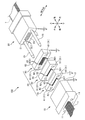
- FIG. 1 is an exploded view of the connector system 100 of the first embodiment.
- FIG. 2 is an explanatory diagram when the connector system 100 of the first embodiment is connected.
- 3A and 3B are explanatory diagrams of an optical system of one unit.
- FIG. 3A is an explanatory view of the optical system of one unit as viewed from above.
- FIG. 3B is an explanatory diagram of the optical system of one unit as viewed from the side (left).
- FIG. 4A is a sectional view of the multi-core fiber 1.
- FIG. 4B is a diagram showing the positional relationship between the multi-core fiber 1 and the first end optical unit 45 by transmitting light from the front-rear direction.
- FIG. 5 is an explanatory diagram of an optical system (optical system unit) of one unit.
- FIG. 1 is an exploded view of the connector system 100 of the first embodiment.
- FIG. 2 is an explanatory diagram when the connector system 100 of the first embodiment is connected.
- 3A and 3B are explanatory
- FIG. 6 is an explanatory view of the optical system (optical system unit) of one unit viewed from another direction.
- FIG. 7A is a cross-sectional view of another multicore fiber 1.
- FIG. 7B is a diagram showing the positional relationship between the multi-core fiber 1 and the first end optical unit 45 by transmitting light from the front-rear direction.
- FIG. 7C is an explanatory view of the multi-core fiber 1 and the first end optical unit 45 seen from the side (left).
- FIG. 8 is an exploded explanatory view of the connector system 100 of the third embodiment.
- a guide pin is provided on one of the first ferrule and the second ferrule, and a guide hole is provided on the other, Through holes are provided in the optical connecting member, By fitting the guide pin into the guide hole through the through hole, it is possible to position the first ferrule, the optical connecting member, and the second ferrule, and a connector system is clarified.
- the multi-core fiber, the single-core fiber, and the optical connecting member can be positioned with high accuracy with a simple structure.
- the optical connection member includes a first lens plate arranged on an end surface of the first ferrule, a second lens plate arranged on an end surface of the second ferrule, the first lens plate and the second lens plate. And a relay plate disposed between the first lens plate and the first lens plate, wherein the first lens plate has a plurality of first lenses corresponding to the multi-core fiber, and the second lens plate has a plurality of single-core fibers.
- a plurality of second lenses corresponding to the plurality of first lenses, and the relay plate includes a plurality of first optical elements corresponding to the plurality of first lenses, and a plurality of first optical elements corresponding to the plurality of second lenses.
- the first lens is configured such that parallel light is propagated between the first lens and the first optical element, and the second lens and the second optical element are provided.
- the second lens is configured so that parallel light is propagated to and from the element, and the second lens is configured to propagate an optical signal between the first optical element and the second optical element. It is desirable that one optical element and the second optical element are configured. Thereby, even if the arrangement of the cores of the multi-core fiber (2 ⁇ 2 arrangement) is different from the arrangement of the plurality of single-core fibers (1 ⁇ 4 arrangement), the multi-core fiber and the plurality of single-core fibers can be simply structured. Can be optically connected.
- the first lens plate has a plurality of first end optical elements corresponding to the plurality of cores of the multi-core fiber, and is provided between the plurality of first end optical elements and the plurality of first lenses. It is preferable that the plurality of first end optical elements are configured such that the intervals of the respective optical paths formed become wider toward the relay plate side. Thereby, interference (crosstalk) of optical signals can be suppressed.
- a direction parallel to the central axis of the multi-core fiber is defined as a front-back direction
- normal lines of a plurality of planes forming the plurality of first end optical elements are all inclined with respect to the front-back direction. desirable. This can suppress the influence of reflection of the optical signal on the first end optical element.
- the plurality of second optical elements corresponding to the multi-core fibers are arranged along a direction perpendicular to the width direction. Is desirable. Accordingly, since the plurality of second optical elements can be arranged in the narrow region in the width direction, it becomes easy to arrange a large number of fiber holes in the predetermined region in the width direction of the connection end face of the second ferrule.
- the parallel light propagating between the second lens and the second optical element is preferably in a direction parallel to the axial direction of the guide pin. Thereby, signal loss can be suppressed.
- first ferrule that holds the ends of a plurality of multi-core fibers
- second ferrule that holds the ends of a plurality of single-core fibers
- optical connection member having a through hole
- the optical connection member between the first ferrule and the second ferrule, a guide pin is provided on one of the first ferrule and the second ferrule, and a guide hole is provided on the other of the first ferrule and the second ferrule.
- a relay plate for propagating an optical signal between the first lens and the second lens is provided, and a pair of through holes is provided in each of the first lens plate, the second lens plate and the relay plate.
- the first lens plate, the second lens plate and the relay plate are connected to the first ferrule and An optical connecting member that can be positioned with respect to the second ferrule becomes clear. According to such an optical connecting member, the multi-core fiber, the single-core fiber, and the optical connecting member can be positioned with high accuracy with a simple structure.
- FIG. 1 is an exploded view of the connector system 100 of the first embodiment.
- FIG. 2 is an explanatory diagram when the connector system 100 of the first embodiment is connected.
- 3A and 3B are explanatory diagrams of an optical system of one unit.
- FIG. 3A is an explanatory view of the optical system of one unit as viewed from above.
- FIG. 3B is an explanatory diagram of the optical system of one unit as viewed from the side (left).
- each direction is defined as shown in Fig. 1.
- the direction parallel to the axial direction of the guide pin 25 is the front-back direction, the side of the first ferrule 10 is “front”, and the side of the second ferrule 20 is “rear”. ".
- the direction in which the plurality of multi-core fibers 1 held by the first ferrule 10 are arranged is referred to as the “width direction” or the “left-right direction”.
- a direction perpendicular to the front-rear direction and the width direction is referred to as "up-down direction”.
- the side of the protruding edge of the inclined end surface of the first ferrule 10 is “lower” and the opposite side is "upper”.
- the connector system 100 of this embodiment is a structure that optically connects the multi-core fiber 1 and the single-core fiber 7.
- FIG. 4A is a cross-sectional view of the multi-core fiber 1.
- the multi-core fiber 1 is an optical fiber having a plurality of cores 3.
- the suffixes A to D are added to the symbols of the respective cores.
- the same suffix as the corresponding core 3 of the member or part may be attached to the reference numeral of the member or part.
- the multi-core fiber 1 may be referred to as “MC fiber” or “MCF”.
- the single-core fiber 7 (see FIG. 3B) is an optical fiber (single core fiber) having one core.
- the single-core fiber 7 is a single-mode optical fiber, and in the following description, the single-core fiber 7 may be referred to as “SM fiber” or “SMF”.
- the single-core fiber 7 is not limited to a single-mode optical fiber, and may be a multi-mode optical fiber.
- the single core fiber 7 is optically connected to each core 3 included in the multi-core fiber 1. That is, in the present embodiment, four single-core fibers 7 are optically connected to one multi-core fiber 1.
- the connector system 100 of this embodiment has a first ferrule 10, a second ferrule 20, and a connection unit 30 (see FIG. 1).
- the first ferrule 10 is a ferrule that holds the ends of a plurality of multicore fibers 1.
- the structure of the first ferrule 10 is the same as that of the MT type optical connector (optical connector defined by JIS C 5981, MT: Mechanically Transferable).
- the first ferrule 10 has a pair of guide holes 11 and a plurality of fiber holes 12 (see FIG. 3B: not shown in FIGS. 1 and 2).
- the guide hole 11 is a hole into which the guide pin 25 is inserted.
- the guide hole 11 is formed along the front-rear direction.
- a pair of guide holes 11 are arranged side by side in the width direction.
- the fiber hole 12 is a hole for inserting the multi-core fiber 1.
- the fiber hole 12 is formed along the front-back direction.
- the multi-core fiber 1 is inserted into each fiber hole 12, and the multi-core fiber 1 is fixed inside the fiber hole 12 with an adhesive.
- a plurality (M) of fiber holes 12 are arranged side by side in the width direction.
- twelve fiber holes 12 are arranged side by side in the width direction (in other words, in the connection end face 13 of the first ferrule 10, the end faces of the twelve multicore fibers 1 are arranged side by side in the width direction.
- Exist the end faces of the twelve multicore fibers 1 are arranged side by side in the width direction.
- the end surface of the multicore fiber 1 is exposed from the opening of the fiber hole 12 in the connection end surface 13 of the first ferrule 10.
- the end face of the multicore fiber 1 is exposed from the opening of the fiber hole 12 by polishing the connection end face 13 of the first ferrule 10 with the multicore fiber 1 fixed (bonded) in the fiber hole 12. ing.
- the connection end face 13 of the first ferrule 10 and the end face of the multi-core fiber 1 are inclined at about 8 degrees with respect to the plane perpendicular to the front-back direction. By inclining the end surface of the multi-core fiber 1, it is possible to suppress the influence of reflection of the optical signal on the end surface.
- the connection end face 13 of the first ferrule 10 or the end face of the multicore fiber 1 may be perpendicular to the front-rear direction without inclining the connection end face 13 of the first ferrule 10 or the end face of the multicore fiber 1.
- the second ferrule 20 is a ferrule that holds the ends of the plurality of single-core fibers 7.
- the second ferrule 20 has M ⁇ N single-core fibers 7 Will hold.
- four optical fiber tapes (optical fiber ribbons) each composed of 12 single-core fibers 7 extend from the rear side of the second ferrule 20.
- the structure of the second ferrule 20 is similar to that of the MT type optical connector.
- the second ferrule 20 has a pair of guide holes 21 and a plurality of (here, 48) fiber holes 22.
- the guide pin 25 is inserted into the guide hole 21 of the second ferrule 20, and the guide pin 25 projects from the connection end surface 23 of the second ferrule 20.
- the guide pin 25 may be provided on the first ferrule 10 side instead of the second ferrule 20 side.
- the single-core fiber 7 is inserted into the fiber hole 22 of the second ferrule 20, and the single-core fiber 7 is fixed inside the fiber hole 22 with an adhesive.
- the plurality of fiber holes 22 are arranged so that there are M holes in the width direction and N holes in the vertical direction (in other words, in the connection end face 23 of the second ferrule 20, M holes in the width direction).
- the end faces of N single-core fibers 7 are arranged in the vertical direction.
- the end face of the single-core fiber 7 is exposed from the opening of the fiber hole 22 in the connection end face 23 of the second ferrule 20.
- the connection end face 23 of the second ferrule 20 and the end face of the single-core fiber 7 are inclined at about 8 degrees with respect to the plane perpendicular to the front-back direction. By inclining the end surface of the multi-core fiber 1, it is possible to suppress the influence of reflection of the optical signal on the end surface.
- the connection end face 23 of the second ferrule 20 and the end face of the single core fiber 7 may be perpendicular to the front-rear direction without inclining the connection end face 23 of the second ferrule 20 and the end face of the single core fiber 7.
- the connection unit 30 is an optical connection member that optically connects each core 3 of the multi-core fiber 1 and the single-core fiber 7.
- the connection unit 30 may be called a fan-out member (or a fan-out structure or a fan-out unit).
- the connection unit 30 will be arranged between the first ferrule 10 and the second ferrule 20.
- the connection unit 30 is made of a material capable of transmitting an optical signal.
- the connection unit 30 has an optical system that optically connects the respective cores 3 of the multi-core fiber 1 and the single-core fiber 7.
- M (12 here) connection units.
- M optical system units are provided corresponding to each multi-core fiber 1, and are arranged side by side in the width direction.
- FIG. 5 and 6 are explanatory views of an optical system (optical system unit) of one unit.
- the optical system one optical system unit
- the optical system for optically connecting N (here, four) single-core fibers 7 to one multi-core fiber 1 is the first optical system 44 and the optical path conversion. It has an optical system 54 and a second optical system 64.
- a virtual lens barrel of the optical system is shown by a dotted line.
- the lens barrel indicated by the dotted line does not actually exist, and each of the M optical systems arranged in the width direction is integrated by an optical component (a first lens plate 40, a relay plate 50, or a second lens plate 60 described later).
- the virtual lens barrel of the optical system of one unit is shown by a dotted line in the figure, but there is a boundary (for example, a lens barrel) between the M optical systems arranged in the width direction. is not.
- the optical elements (elements) constituting each optical system will be described later.
- the connection unit 30 has a pair of through holes 31. M optical system units are arranged between the pair of through holes 31.
- the through hole 31 is a hole through which the guide pin 25 is inserted.
- the second ferrule 20 and the connection unit 30 are aligned with each other.
- the guide pin 25 of the second ferrule 20 into the guide hole 11 of the first ferrule 10 through the through hole 31 of the connection unit 30, the first ferrule 10, the connection unit 30, and the second ferrule 20 can be joined together. It is possible to position them together.
- the first ferrule 10, the connection unit 30, and the second ferrule 20 can be passively positioned with a simple configuration.
- the three members of the multi-core fiber 1, the single-core fiber 7, and the optical system that optically connects the multi-core fiber 1 and the single-core fiber 7 can be passively positioned with a simple configuration.
- a spring mechanism presses the first ferrule 10 toward the second ferrule 20 and presses the second ferrule 20 toward the first ferrule 10.
- the front end surface of the connection unit 30 (the end surface on the side of the first ferrule 10; the first end surface 42 of the first lens plate 40) is abutted against the connection end surface 13 of the first ferrule 10, and the connection of the first ferrule 10 is made. It is in contact with the end surface 13.
- the connection unit 30 and the first ferrule 10 are positioned in the front-rear direction.
- the front end surface of the connection unit 30 is also inclined.
- connection unit 30 (the end surface on the second ferrule 20 side; the second end surface 63 of the second lens plate 60) is abutted against the connection end surface 23 of the second ferrule 20, and It is in contact with the connection end face 23 of the ferrule 20.
- the connection unit 30 and the second ferrule 20 are positioned in the front-rear direction.
- the front end surface of the connection unit 30 is also inclined.
- the connection unit 30 includes a first lens plate 40, a relay plate 50, and a second lens plate 60.
- the first lens plate 40 splits the light into N optical paths, and four parallel lights are emitted from the first lens plate 40 to the relay plate 50.
- the four parallel lights that have entered the relay plate 50 have their optical paths changed by the relay plate 50, and are emitted to the second lens plate 60 as four parallel lights arranged in the vertical direction.
- the four parallel lights that have entered the second lens plate 60 are focused by the second lens plate 60 and enter the end faces of the respective single-core fibers 7.
- four parallel lights are emitted from the second lens plate 60 to the relay plate 50.
- the four parallel lights that have entered the relay plate 50 have their respective optical paths converted by the relay plate 50, and are emitted to the first lens plate 40 as four parallel lights arranged in two in the width direction and two in the vertical direction. It The four parallel lights that have entered the first lens plate 40 are focused by the first lens plate 40 and enter the respective cores 3 of the multi-core fiber 1.
- the case where light is emitted from the multi-core fiber 1 will be mainly described, and the case where light is emitted from the four single-core fibers 7 may be omitted.
- the first lens plate 40 is a plate attached to the connection end surface 13 of the first ferrule 10.
- the first lens plate 40 collimates the light emitted from each core 3 of the multi-core fiber 1 and outputs the parallel light to the relay plate 50.
- the first lens plate 40 focuses the parallel light incident from the relay plate 50 on each core 3 of the multi-core fiber 1.
- the first lens plate 40 is made of a material capable of transmitting an optical signal.
- the first lens plate 40 may also be called a first collimator plate, an MCF-side collimator plate, or the like.
- the first lens plate 40 has a pair of through holes 41, a first end surface 42, a second end surface 43, and a plurality (M) of first optical systems 44.
- the through hole 41 is a hole that constitutes a part of the through hole 31 of the connection unit 30, and is a hole through which the guide pin 25 is inserted.
- a plurality of first optical systems 44 (and a first recess 421 and a second recess 431) are arranged between the pair of through holes 41.
- the first end surface 42 is an end surface that contacts the connection end surface 13 of the first ferrule 10.
- the first end face 42 is brought into contact with the connection end face 13 of the first ferrule 10 to position the first lens plate 40 and the first ferrule 10 in the front-rear direction.
- the connection end surface 13 of the first ferrule 10 since the connection end surface 13 of the first ferrule 10 is inclined, the first end surface 42 (front end surface of the connection unit 30) is also inclined.
- a first recess 421 is formed on the first end surface 42.
- the second end surface 43 is an end surface that contacts the relay plate 50. The second end surface 43 is abutted against the first end surface 52 of the relay plate 50, whereby the first lens plate 40 and the relay plate 50 are positioned in the front-rear direction.
- a second recess 431 is formed in the second end surface 43.
- the first recess 421 is a recess formed in the first end face 42 on the front side of the first lens plate 40 (first ferrule 10 side; multicore fiber 1 side).
- the second recess 431 is a recess formed in the second end surface 43 on the rear side (the relay plate 50 side) of the first lens plate 40.
- Optical elements of the first optical system 44 (first end optical unit 45 and first lens unit 46) are formed on the bottom surfaces of the first concave portion 421 and the second concave portion 431.
- the first optical system 44 is an optical system configured on the first lens plate 40.
- the first lens plate 40 has M first optical systems 44 arranged in the width direction.
- the first optical system 44 has a first end optical unit 45 and a first lens unit 46.
- the first end optical unit 45 is an optical element (optical element group) arranged to face the multi-core fiber 1.
- the first end optical unit 45 has a function of widening the optical path intervals of a plurality (here, four) of optical signals corresponding to the respective cores 3 of the multi-core fiber 1 toward the relay plate 50.
- the first end optical unit 45 is configured as an N-branch prism.
- the first end optical unit 45 is configured as a four-branch prism, and has a pyramid shape (a tetrahedron shape that is recessed from the bottom surface of the recess into an inverted pyramid shape).
- FIG. 4B is a diagram showing a positional relationship between the multi-core fiber 1 and the first end optical unit 45 by transmitting light from the front-rear direction.
- the first end optical unit 45 includes a plurality (N) of first end optical elements 451.
- the first end optical element 451 is an optical element (prism surface) arranged to face the core 3 of the multi-core fiber 1.
- the first end optical element 451 forms a boundary surface (an inclined surface) that refracts an optical signal.
- the first end optical element 451 has a function of changing the optical path of an optical signal.
- the normal directions of the plurality of first end optical elements 451 are different from each other.
- the plurality of first end optical elements 451 are inclined surfaces that are inclined in different directions.
- the four first end optical elements 451 form a pyramid-shaped first end optical unit 45 (four-branch prism).
- the plurality of first end optical elements 451 are configured such that the intervals of the plurality of optical paths formed between the first end optical unit 45 and the first lens unit 46 become wider toward the relay plate 50 side. There is.
- the first end optical unit 45 is formed in a pyramid shape (a tetrahedron shape in which the bottom surface of the recess is recessed in an inverted pyramid shape), and the four first ends that form the first end optical unit 45 are formed.
- the normal line of the optical element 451 (prism surface) is inclined with respect to the front-back direction (direction parallel to the central axis of the multicore fiber 1). As a result, the influence of the reflection of the optical signal on the first end optical element 451 (the optical signal reflected on the first end optical element 451 returns to the core 3 of the multi-core fiber 1) can be suppressed.
- the first lens unit 46 is an optical element (optical element group) arranged corresponding to the first end optical unit 45.
- the first lens unit 46 is an optical element (optical element group) arranged corresponding to the multi-core fiber 1.
- the first lens unit 46 has a function of collimating light emitted from each core 3 of the multi-core fiber 1 and a function of focusing incident parallel light on each core 3 of the multi-core fiber 1.
- the first lens unit 46 has a plurality (N pieces) of first lenses 461.
- the first lens 461 is an optical element (lens) arranged corresponding to the core 3 of the multi-core fiber 1 and the first end optical element 451.
- the first lens 461 is a collimator lens, and has a function of making light emitted from the core 3 into parallel light and a function of focusing incident parallel light.
- the first lens 461 is configured such that parallel light is propagated between the first lens plate 40 and the relay plate 50 (specifically, between the first lens 461 and the first optical element 551). Has been done.
- the first lens unit 46 has four first lenses 461 arranged in two in the width direction and two in the vertical direction.
- the distance between the optical paths is widened by the first end optical unit 45, the distance between the two first lenses 461 arranged in the width direction or the vertical direction is set wider than the distance between the cores 3 of the multi-core fiber 1. can do.
- the first end optical unit 45 can suppress the interference (crosstalk) of optical signals.
- the first end optical unit 45 may not be provided on the first lens plate 40 if there is no problem of optical signal interference.
- the first end surface 42 of the first lens plate 40 and the end surface of the multi-core fiber 1 are It is desirable that the gap is filled with a refractive index matching agent.
- the relay plate 50 is a plate arranged between the first lens plate 40 and the second lens plate 60.
- the relay plate 50 outputs the parallel light incident from the first lens plate 40 to the second lens plate 60 as the parallel light.
- the relay plate 50 outputs the parallel light incident from the second lens plate 60 to the first lens plate 40 as the parallel light.
- the relay plate 50 is made of a material capable of transmitting an optical signal.
- the relay plate 50 is sometimes called an optical path changing plate, a beam steering plate, or a prism device.
- the relay plate 50 has a pair of through holes 51, a first end surface 52, a second end surface 53, and a plurality (M) of optical path conversion optical systems 54.
- the through hole 51 is a hole that constitutes a part of the through hole 31 of the connection unit 30, and is a hole through which the guide pin 25 is inserted.
- a plurality of optical path conversion optical systems 54 (and the first recess 521 and the second recess 531) are arranged between the pair of through holes 51.
- the first end surface 52 is an end surface that contacts the first lens plate 40.
- a first recess 521 is formed on the first end surface 52.
- the second end surface 53 is an end surface that contacts the second lens plate 60. By positioning the second end surface 53 against the first end surface 62 of the second lens plate 60, the relay plate 50 and the second lens plate 60 are positioned in the front-rear direction.
- a second recess 531 is formed on the second end surface 53.
- the first recess 521 is a recess formed in the first end surface 52 on the front side (the first lens plate 40 side) of the relay plate 50.
- the second recess 531 is a recess formed on the second end surface 53 on the rear side (on the side of the second lens plate 60) of the relay plate 50.
- Optical elements (first optical unit 55, second optical unit 56) of the optical path conversion optical system 54 are formed on the bottom surfaces of the first concave portion 521 and the second concave portion 531.
- the optical path changing optical system 54 is an optical system configured on the relay plate 50.
- the relay plate 50 has M optical path changing optical systems 54 arranged in the width direction.
- the optical path conversion optical system 54 is configured by the prism optical system.
- the optical path changing optical system 54 has a first optical unit 55 and a second optical unit 56.
- the first optical unit 55 is an optical element (optical element group) arranged so as to face the first lens unit 46.
- the first optical unit 55 has a plurality (N) of first optical elements 551.
- the first optical element 551 is an optical element (prism surface) arranged to face the first lens 461 of the first lens unit 46.
- the first optical element 551 forms a boundary surface (an inclined surface) that refracts an optical signal.
- the first optical element 551 has a function of changing the optical path of an optical signal.
- the normal directions of the plurality of first optical elements 551 are different from each other. In other words, the plurality of first optical elements 551 are inclined surfaces inclined in different directions.
- Each first optical element 551 is configured to propagate an optical signal with the corresponding second optical element 561.
- the second optical unit 56 is an optical element arranged to face the second lens unit 65.
- the second optical unit 56 has a plurality (N) of second optical elements 561.
- the second optical element 561 is an optical element (prism surface) arranged to face the second lens 651 of the second lens unit 65.
- the second optical element 561 forms a boundary surface (an inclined surface) that refracts an optical signal.
- the second optical element 561 has a function of changing the optical path of an optical signal.
- the plurality of second optical elements 561 have different normal directions. In other words, the plurality of second optical elements 561 are inclined surfaces that are inclined in different directions.
- Each second optical element 561 is configured to propagate an optical signal with the corresponding first optical element 551.
- the four first optical elements 551 of the first optical unit 55 are arranged in two in the width direction and two in the vertical direction (2 ⁇ 2 arrangement).
- the four second optical elements 561 of the second optical unit 56 are arranged in one in the width direction and four in the vertical direction (1 ⁇ 4 arrangement).
- an array of four first optical elements 551 here, a 2 ⁇ 2 array
- four The arrangement of the second optical elements 561 here, 1 ⁇ 4 arrangement
- the optical path changing optical system 54 is configured to change the respective optical paths between the four first optical elements 551 and the four second optical elements 561 having different arrangements.
- the second lens plate 60 is a plate attached to the connection end surface 23 of the second ferrule 20.
- the second lens plate 60 focuses the parallel light incident from the relay plate 50 on the single-core fiber 7.
- the second lens plate 60 collimates the light emitted from the single-core fiber 7 and emits it to the relay plate 50.
- the second lens plate 60 is made of a material capable of transmitting an optical signal.
- the second lens plate 60 may also be called a second collimator plate, an SMF side collimator plate, or the like.
- the second lens plate 60 has a pair of through holes 61, a first end face 62, a second end face 63, and a plurality (M) of second optical systems 64.
- the through hole 61 is a hole that constitutes a part of the through hole 31 of the connection unit 30, and is a hole through which the guide pin 25 is inserted.
- the first recess 621 and the plurality of second optical systems 64 are arranged between the pair of through holes 61.
- the first end surface 62 is an end surface that contacts the relay plate 50.
- a first recess 621 is formed in the first end surface 62.
- the second end surface 63 is an end surface that contacts the connection end surface 23 of the second ferrule 20.
- the second end face 63 is brought into contact with the connecting end face 23 of the second ferrule 20, whereby the second lens plate 60 and the second ferrule 20 are positioned in the front-rear direction.
- the 2nd end surface 63 is comprised in the plane.
- the connection end surface 23 of the second ferrule 20 is inclined, the second end surface 63 (rear end surface of the connection unit 30) is also an inclined flat surface.
- the second end surface 63 forms a signal surface that allows an optical signal to enter or exit the single-core fiber 7.
- the first recess 621 is a recess formed in the first end surface 62 on the front side (the relay plate 50 side) of the second lens plate 60.
- An optical element (second lens unit 65) of the second optical system 64 is formed on the bottom surface of the first recess 621.
- the second optical system 64 is an optical system configured on the second lens plate 60.
- the second lens plate 60 has M second optical systems 64 arranged in the width direction.
- the second optical system 64 has a second lens unit 65.
- the second lens unit 65 is an optical element (optical element group) arranged corresponding to a plurality (N) of single-core fibers 7.
- the second lens unit 65 is an optical element (optical element group) arranged corresponding to the multi-core fiber 1.
- the second lens unit 65 has a plurality (N) of second lenses 651.
- the second lens 651 is an optical element (lens) arranged corresponding to the single-core fiber 7.
- the second lens 651 is a collimator lens and has a function of focusing incident parallel light and a function of converting light emitted from the single-core fiber 7 into parallel light.
- the second lens 651 is configured such that parallel light is propagated between the second lens plate 60 and the relay plate 50 (specifically, between the second lens 651 and the second optical element 561). Has been done.
- the second lens unit 65 has four second lenses 651 arranged vertically.
- the connection unit 30 (optical connection member) of this embodiment has the first lens plate 40, the second lens plate 60, and the relay plate 50.
- the first lens plate 40 has a plurality of first lenses 461 corresponding to the multi-core fiber 1, and the first lenses 461 are parallel to each other between the first lenses 461 and the first optical element 551 of the relay plate 50. It is configured to propagate light.
- the second lens plate 60 has a plurality of second lenses 651 corresponding to the respective single-core fibers 7, and the second lens 651 includes the second lens 651 and the second optical element 561 of the relay plate 50. It is configured such that parallel light is propagated between them.
- the four first lenses 461 of the first lens unit 46 are arranged in two in the width direction and two in the vertical direction (2 ⁇ 2), as in the core arrangement of the multi-core fiber 1 (see FIG. 4B). Are arranged).
- the four second lenses 651 of the second lens unit 65 are arranged in one in the width direction and four in the vertical direction (1 ⁇ 4 arrangement).
- the optical path conversion optical system 54 of the relay plate 50 (the first optical element 551 and the second optical element 551 and the second optical element 561) is configured so that the optical signal is propagated between the first optical element 551 and the second optical element 561.
- a prism optical system is constituted by the element 561.
- the multi-core fiber 1 and the plurality of single-core fibers 1 are arranged with a simple configuration.
- the optical fiber 7 can be optically connected.
- the pair of through holes 31 is provided in each of the first lens plate 40, the second lens plate 60, and the relay plate 50 of the connection unit 30, and the first ferrule 10 and the second ferrule 20 are connected to each other.
- the first lens plate 40, the second lens plate 60, and the relay plate 50 can be positioned with respect to the first ferrule 10 and the second ferrule 20.
- the first lens plate 40, the second lens plate 60, and the relay plate 50 can be positioned with respect to the first ferrule 10 and the second ferrule 20 with a simple configuration
- the multi-core fiber 1 and a plurality of multi-core fibers 1 can be positioned with a simple configuration.
- the optical fiber can be optically connected to the single-core fiber 7.
- the first lens plate 40, the second lens plate 60, and the relay plate 50 of the connection unit 30 are composed of different members, but the connection unit 30 may be integrated.
- the plurality of first end optical elements 451 are arranged so that the intervals of the plurality of optical paths formed between the first end optical unit 45 and the first lens unit 46 become wider toward the relay plate 50. It is configured. As a result, the first end optical unit 45 can suppress the interference (crosstalk) of the optical signal.
- the plurality (M) of multi-core fibers 1 held by the first ferrule 10 are arranged side by side in the width direction (left-right direction).
- the plurality of (N) second optical elements 561 corresponding to the respective multi-core fibers 1 are arranged along the vertical direction perpendicular to the width direction. Accordingly, a plurality (N) of the second optical elements 561 can be arranged in a narrow region in the width direction, so that a large number (M ⁇ N) are provided in a predetermined region in the width direction of the connection end face 23 of the second ferrule 20.
- the fiber holes 22 can be arranged.
- the parallel light propagating between the second lens 651 of the second lens plate 60 and the second optical element 561 of the relay plate 50 is parallel to the axial direction of the guide pin 25 (front and rear). Direction).
- FIG. 7A is a cross-sectional view of another multicore fiber 1.
- the number of cores 3 of the multi-core fiber 1 is not limited to four and may be seven. When the number of cores 3 of the multi-core fiber 1 is 7, the core 3D may be arranged on the central axis of the multi-core fiber 1.
- FIG. 7B is a diagram showing a positional relationship between the multi-core fiber 1 and the first end optical unit 45 by transmitting light from the front-rear direction.
- FIG. 7C is an explanatory diagram of the multi-core fiber 1 and the first end optical unit 45 seen from the left and right direction. Also in the second embodiment, the normal lines of the seven first end optical elements 451 (prism surfaces) forming the first end optical unit 45 (7-branch prism) are all in the front-back direction (the central axis of the multi-core fiber 1). Direction parallel to)).
- the normal line of the first end optical element 451D located at the center is in the front-rear direction, and as a result, Since the optical signal reflected by the end optical element 451D returns to the core 3D of the multi-core fiber 1, it may be affected by the reflected return light.
- the normal line of the first end optical element 451D (prism surface) is inclined with respect to the front-back direction. doing.
- the normal line of the plurality (N) of the first end optical elements 451 (prism surfaces) forming the first end optical unit. It is desirable that both are inclined with respect to the front-back direction. As a result, the influence of the reflection of the optical signal on the first end optical element 451 can be suppressed.
- N when the number of cores 3 included in one multi-core fiber 1 is N, N is not limited to 4, and another number may be used. Similarly, when the number of the multi-core fibers 1 held by the first ferrule 10 is M, M is not limited to 12 and may be another number.
- FIG. 8 is an exploded explanatory view of the connector system 100 of the third embodiment.
- the first lens ferrule 10 is formed by adhering the first lens plate 40 to the first ferrule 10 in advance.
- the second lens ferrule is configured by preliminarily bonding and fixing the second lens plate 60 to the second ferrule 20.
- the relay plate 50 is arranged between the first lens ferrule and the second lens ferrule.
- the respective configurations of the first ferrule 10, the second ferrule 20, and the connection unit 30 (the first lens plate 40, the relay plate 50, and the second lens plate 60) of the third embodiment are the same as those of the first embodiment (or the first embodiment). 2 embodiment).
- the first ferrule 10, the connection unit 30 (particularly the relay plate 50), and the second ferrule 20 can be passively positioned with a simple configuration.
- the three members of the multi-core fiber 1, the single-core fiber 7, and the optical system that optically connects the multi-core fiber 1 and the single-core fiber 7 can be passively positioned with a simple configuration.
Landscapes
- Physics & Mathematics (AREA)
- General Physics & Mathematics (AREA)
- Optics & Photonics (AREA)
- Optical Couplings Of Light Guides (AREA)
- Mechanical Coupling Of Light Guides (AREA)
Abstract
Le problème décrit par la présente invention est d'aligner avec précision une fibre multi-coeur, une fibre à coeur unique et un élément de connexion optique avec une configuration simple. À cet effet, l'invention concerne un système de connecteur qui comprend : une première férule qui maintient des parties d'extrémité d'une pluralité de fibres multicoeurs ; une seconde férule qui maintient des parties d'extrémité d'une pluralité de fibres à coeur unique ; et un élément de connexion optique. L'élément de connexion optique est placé entre la première férule et la seconde férule et a un système optique pour connecter optiquement les coeurs de chaque fibre multicoeur et les fibres à coeur unique. Une broche de guidage est disposée sur l'une de la première férule et de la seconde férule et un trou de guidage est prévu sur l'autre. L'élément de connexion optique comporte un trou traversant, et la première férule, l'élément de connexion optique et la seconde férule peuvent être alignés par ajustement de la broche de guidage dans le trou de guidage à travers le trou traversant,
Priority Applications (2)
| Application Number | Priority Date | Filing Date | Title |
|---|---|---|---|
| CN201980076523.5A CN113167974B (zh) | 2018-12-25 | 2019-10-02 | 连接器系统、光连接方法以及光连接部件 |
| US17/312,772 US11947170B2 (en) | 2018-12-25 | 2019-10-02 | Connector system, optical connection method, and optical connection member |
Applications Claiming Priority (2)
| Application Number | Priority Date | Filing Date | Title |
|---|---|---|---|
| JP2018-240880 | 2018-12-25 | ||
| JP2018240880A JP6864666B2 (ja) | 2018-12-25 | 2018-12-25 | コネクタシステム、光接続方法及び光接続部材 |
Publications (1)
| Publication Number | Publication Date |
|---|---|
| WO2020137070A1 true WO2020137070A1 (fr) | 2020-07-02 |
Family
ID=71126266
Family Applications (1)
| Application Number | Title | Priority Date | Filing Date |
|---|---|---|---|
| PCT/JP2019/038912 WO2020137070A1 (fr) | 2018-12-25 | 2019-10-02 | Système de connecteur, procédé de connexion optique et élément de connexion optique |
Country Status (4)
| Country | Link |
|---|---|
| US (1) | US11947170B2 (fr) |
| JP (1) | JP6864666B2 (fr) |
| CN (1) | CN113167974B (fr) |
| WO (1) | WO2020137070A1 (fr) |
Cited By (1)
| Publication number | Priority date | Publication date | Assignee | Title |
|---|---|---|---|---|
| JPWO2022137632A1 (fr) * | 2020-12-23 | 2022-06-30 |
Families Citing this family (1)
| Publication number | Priority date | Publication date | Assignee | Title |
|---|---|---|---|---|
| WO2023033177A1 (fr) | 2021-09-03 | 2023-03-09 | 株式会社エンプラス | Connecteur optique et module de connecteur optique |
Citations (8)
| Publication number | Priority date | Publication date | Assignee | Title |
|---|---|---|---|---|
| JP2003232963A (ja) * | 2002-02-07 | 2003-08-22 | Furukawa Electric Co Ltd:The | レンズ交換型コリメータを備えた機能性光結合モジュール |
| JP2013057842A (ja) * | 2011-09-09 | 2013-03-28 | Konica Minolta Advanced Layers Inc | 結合光学系 |
| JP2013065002A (ja) * | 2011-09-01 | 2013-04-11 | Konica Minolta Advanced Layers Inc | 結合光学系及び結合方法 |
| JP2013076893A (ja) * | 2011-09-30 | 2013-04-25 | National Institute Of Advanced Industrial & Technology | 多層導波路型光入出力端子 |
| US20150063755A1 (en) * | 2013-08-27 | 2015-03-05 | International Business Machines Corporation | Multicore fiber waveguide coupler |
| WO2015064635A1 (fr) * | 2013-10-29 | 2015-05-07 | 古河電気工業株式会社 | Structure de connecteur, procédé de production de structure de connecteur, et structure de connexion de connecteur |
| US20160246015A1 (en) * | 2013-05-15 | 2016-08-25 | Commscope, Inc. Of North Carolina | Multiple-beam microlen |
| WO2018139184A1 (fr) * | 2017-01-26 | 2018-08-02 | 住友電気工業株式会社 | Composant de connexion optique et structure de couplage optique |
Family Cites Families (9)
| Publication number | Priority date | Publication date | Assignee | Title |
|---|---|---|---|---|
| JP4652631B2 (ja) * | 2001-08-29 | 2011-03-16 | 古河電気工業株式会社 | 光コネクタ用フェルール及び光コネクタ |
| US7040814B2 (en) * | 2001-10-15 | 2006-05-09 | The Furukawa Electric Co., Ltd. | Functional optical module |
| JP4002144B2 (ja) * | 2002-07-10 | 2007-10-31 | 古河電気工業株式会社 | 多芯光コリメータ及びこれを用いた光モジュール |
| US20110026882A1 (en) | 2009-07-31 | 2011-02-03 | International Business Machines Corporation | Lensed optical connector with passive alignment features |
| WO2014038514A1 (fr) | 2012-09-06 | 2014-03-13 | 株式会社オプトクエスト | Fibre multicœur, et instrument de liaison optique pour fibre monomode |
| JP2016095410A (ja) | 2014-11-14 | 2016-05-26 | 住友電気工業株式会社 | グリンレンズアレイ、レンズ付きコネクタ、及びレンズ付きコネクタシステム |
| US20170160491A1 (en) * | 2015-07-20 | 2017-06-08 | Samtec, Inc. | Eye-safe interface for optical connector |
| JP2018092152A (ja) * | 2016-11-30 | 2018-06-14 | 株式会社フジクラ | フェルール構造体、ファイバ付きフェルール構造体及びファイバ付きフェルール構造体の製造方法 |
| JP2018194671A (ja) * | 2017-05-17 | 2018-12-06 | コニカミノルタ株式会社 | 光コネクタ |
-
2018
- 2018-12-25 JP JP2018240880A patent/JP6864666B2/ja active Active
-
2019
- 2019-10-02 WO PCT/JP2019/038912 patent/WO2020137070A1/fr active Application Filing
- 2019-10-02 US US17/312,772 patent/US11947170B2/en active Active
- 2019-10-02 CN CN201980076523.5A patent/CN113167974B/zh active Active
Patent Citations (8)
| Publication number | Priority date | Publication date | Assignee | Title |
|---|---|---|---|---|
| JP2003232963A (ja) * | 2002-02-07 | 2003-08-22 | Furukawa Electric Co Ltd:The | レンズ交換型コリメータを備えた機能性光結合モジュール |
| JP2013065002A (ja) * | 2011-09-01 | 2013-04-11 | Konica Minolta Advanced Layers Inc | 結合光学系及び結合方法 |
| JP2013057842A (ja) * | 2011-09-09 | 2013-03-28 | Konica Minolta Advanced Layers Inc | 結合光学系 |
| JP2013076893A (ja) * | 2011-09-30 | 2013-04-25 | National Institute Of Advanced Industrial & Technology | 多層導波路型光入出力端子 |
| US20160246015A1 (en) * | 2013-05-15 | 2016-08-25 | Commscope, Inc. Of North Carolina | Multiple-beam microlen |
| US20150063755A1 (en) * | 2013-08-27 | 2015-03-05 | International Business Machines Corporation | Multicore fiber waveguide coupler |
| WO2015064635A1 (fr) * | 2013-10-29 | 2015-05-07 | 古河電気工業株式会社 | Structure de connecteur, procédé de production de structure de connecteur, et structure de connexion de connecteur |
| WO2018139184A1 (fr) * | 2017-01-26 | 2018-08-02 | 住友電気工業株式会社 | Composant de connexion optique et structure de couplage optique |
Cited By (2)
| Publication number | Priority date | Publication date | Assignee | Title |
|---|---|---|---|---|
| JPWO2022137632A1 (fr) * | 2020-12-23 | 2022-06-30 | ||
| WO2022137632A1 (fr) * | 2020-12-23 | 2022-06-30 | 株式会社フジクラ | Composant de connexion optique et ensemble connecteur |
Also Published As
| Publication number | Publication date |
|---|---|
| CN113167974A (zh) | 2021-07-23 |
| JP6864666B2 (ja) | 2021-04-28 |
| CN113167974B (zh) | 2023-05-12 |
| US20220050250A1 (en) | 2022-02-17 |
| JP2020101738A (ja) | 2020-07-02 |
| US11947170B2 (en) | 2024-04-02 |
Similar Documents
| Publication | Publication Date | Title |
|---|---|---|
| JP6366602B2 (ja) | カップリングレンズを備えたマルチチャネル光コネクタ | |
| US9753221B2 (en) | Optical coupler for a multicore fiber | |
| US9618711B2 (en) | Apparatus for forming a transceiver interface, ferrule, and optical transceiver component | |
| US10775569B2 (en) | Optical connector and optical connection structure | |
| WO2020137070A1 (fr) | Système de connecteur, procédé de connexion optique et élément de connexion optique | |
| JP6502142B2 (ja) | 光ファイバ付きフェルール、光コネクタシステム及び光ファイバ付きフェルールの製造方法 | |
| CN112305678B (zh) | 光学连接器 | |
| WO2017149844A1 (fr) | Fibre attachée à un connecteur optique et structure de couplage optique | |
| US11467352B2 (en) | Ferrule, fiber-attached ferrule, and method of manufacturing fiber-attached ferrule | |
| JP7198155B2 (ja) | フェルール、ファイバ付きフェルール及びファイバ付きフェルールの製造方法 | |
| JP6506064B2 (ja) | 光中継器、及び、光コネクタ装置 | |
| US20230273376A1 (en) | Optical connection component and connector assembly | |
| JP2020030340A (ja) | 光コネクタ部、及び、光接続構造体 | |
| JP6724092B2 (ja) | 光レセプタクル及び光コネクタシステム | |
| JP2020095183A (ja) | 光コネクタ | |
| JP2007178602A (ja) | 光部品及びその製造方法 | |
| WO2020049799A1 (fr) | Système de prise optique et de connecteur optique | |
| WO2020121619A1 (fr) | Virole et virole équipée de fibres | |
| JP4019418B2 (ja) | マルチ合分波モジュール | |
| JP2023125669A (ja) | フェルール、光コネクタおよび光コネクタモジュール | |
| JP2020095240A (ja) | フェルール及びファイバ付きフェルール | |
| JP2003307646A (ja) | 光モジュール |
Legal Events
| Date | Code | Title | Description |
|---|---|---|---|
| 121 | Ep: the epo has been informed by wipo that ep was designated in this application |
Ref document number: 19905442 Country of ref document: EP Kind code of ref document: A1 |
|
| NENP | Non-entry into the national phase |
Ref country code: DE |
|
| 122 | Ep: pct application non-entry in european phase |
Ref document number: 19905442 Country of ref document: EP Kind code of ref document: A1 |