WO2020137058A1 - 燃料電池のセルスタック - Google Patents
燃料電池のセルスタック Download PDFInfo
- Publication number
- WO2020137058A1 WO2020137058A1 PCT/JP2019/037970 JP2019037970W WO2020137058A1 WO 2020137058 A1 WO2020137058 A1 WO 2020137058A1 JP 2019037970 W JP2019037970 W JP 2019037970W WO 2020137058 A1 WO2020137058 A1 WO 2020137058A1
- Authority
- WO
- WIPO (PCT)
- Prior art keywords
- rod
- manifold
- interface region
- region
- shaped crystal
- Prior art date
- Legal status (The legal status is an assumption and is not a legal conclusion. Google has not performed a legal analysis and makes no representation as to the accuracy of the status listed.)
- Ceased
Links
Images

Classifications
-
- H—ELECTRICITY
- H01—ELECTRIC ELEMENTS
- H01M—PROCESSES OR MEANS, e.g. BATTERIES, FOR THE DIRECT CONVERSION OF CHEMICAL ENERGY INTO ELECTRICAL ENERGY
- H01M8/00—Fuel cells; Manufacture thereof
- H01M8/02—Details
- H01M8/0271—Sealing or supporting means around electrodes, matrices or membranes
- H01M8/028—Sealing means characterised by their material
- H01M8/0282—Inorganic material
-
- B—PERFORMING OPERATIONS; TRANSPORTING
- B32—LAYERED PRODUCTS
- B32B—LAYERED PRODUCTS, i.e. PRODUCTS BUILT-UP OF STRATA OF FLAT OR NON-FLAT, e.g. CELLULAR OR HONEYCOMB, FORM
- B32B15/00—Layered products comprising a layer of metal
- B32B15/04—Layered products comprising a layer of metal comprising metal as the main or only constituent of a layer, which is next to another layer of the same or of a different material
-
- H—ELECTRICITY
- H01—ELECTRIC ELEMENTS
- H01M—PROCESSES OR MEANS, e.g. BATTERIES, FOR THE DIRECT CONVERSION OF CHEMICAL ENERGY INTO ELECTRICAL ENERGY
- H01M8/00—Fuel cells; Manufacture thereof
- H01M8/02—Details
- H01M8/0271—Sealing or supporting means around electrodes, matrices or membranes
- H01M8/0276—Sealing means characterised by their form
-
- H—ELECTRICITY
- H01—ELECTRIC ELEMENTS
- H01M—PROCESSES OR MEANS, e.g. BATTERIES, FOR THE DIRECT CONVERSION OF CHEMICAL ENERGY INTO ELECTRICAL ENERGY
- H01M8/00—Fuel cells; Manufacture thereof
- H01M8/10—Fuel cells with solid electrolytes
- H01M8/12—Fuel cells with solid electrolytes operating at high temperature, e.g. with stabilised ZrO2 electrolyte
- H01M2008/1293—Fuel cells with solid oxide electrolytes
-
- H—ELECTRICITY
- H01—ELECTRIC ELEMENTS
- H01M—PROCESSES OR MEANS, e.g. BATTERIES, FOR THE DIRECT CONVERSION OF CHEMICAL ENERGY INTO ELECTRICAL ENERGY
- H01M8/00—Fuel cells; Manufacture thereof
- H01M8/24—Grouping of fuel cells, e.g. stacking of fuel cells
- H01M8/2465—Details of groupings of fuel cells
- H01M8/2484—Details of groupings of fuel cells characterised by external manifolds
- H01M8/2485—Arrangements for sealing external manifolds; Arrangements for mounting external manifolds around a stack
-
- Y—GENERAL TAGGING OF NEW TECHNOLOGICAL DEVELOPMENTS; GENERAL TAGGING OF CROSS-SECTIONAL TECHNOLOGIES SPANNING OVER SEVERAL SECTIONS OF THE IPC; TECHNICAL SUBJECTS COVERED BY FORMER USPC CROSS-REFERENCE ART COLLECTIONS [XRACs] AND DIGESTS
- Y02—TECHNOLOGIES OR APPLICATIONS FOR MITIGATION OR ADAPTATION AGAINST CLIMATE CHANGE
- Y02E—REDUCTION OF GREENHOUSE GAS [GHG] EMISSIONS, RELATED TO ENERGY GENERATION, TRANSMISSION OR DISTRIBUTION
- Y02E60/00—Enabling technologies; Technologies with a potential or indirect contribution to GHG emissions mitigation
- Y02E60/30—Hydrogen technology
- Y02E60/50—Fuel cells
Definitions
- the present invention relates to a fuel cell stack.
- a conventional fuel cell stack includes fuel cells, a manifold made of metal, and a glass portion made of crystallized glass (see Patent Document 1).
- the manifold has a through hole into which the fuel cell is inserted.
- the glass portion joins the fuel cell and the manifold.
- the glass portion divides an internal space (for example, a space to which the fuel gas is supplied) and an external space (for example, a space to which the air is supplied) of the manifold from each other to prevent mixing of the fuel gas and the air.
- the present invention aims to provide a bonded body capable of suppressing the occurrence of cracks in the glass part.
- the joined body according to the present invention includes a first member to be joined and a glass portion to be joined to the surface of the first member to be joined.
- the glass portion includes an interface region within 5 ⁇ m from the surface of the first member to be joined and an internal region exceeding 5 ⁇ m from the surface of the first member to be joined.
- Each of the interface region and the internal region includes rod-shaped crystal grains having an aspect ratio of 3 or more in a sectional view.
- the average orientation angle of the rod-shaped crystal grains included in the interface region is 60 degrees or more and 120 degrees or less.
- the standard deviation of the orientation angle of the rod-shaped crystal grains contained in the inner region is larger than the standard deviation of the orientation angle of the rod-shaped crystal grains contained in the interface region.
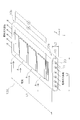
- FIG. 1 is an overall perspective view of the cell stack 1.
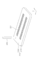
- FIG. 2 is an overall perspective view of the fuel cell 100.
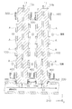
- FIG. 3 is an overall perspective view of the manifold 200.
- FIG. 4 is a partially enlarged cross-sectional view of the fuel cell 100 and the manifold 200.
- the cell stack 1 is a structure used for a solid oxide fuel cell (SOFC; Solid Oxide Fuel Cell).
- SOFC Solid Oxide Fuel Cell
- an x, y, z coordinate system is set.
- the cell stack 1 includes a plurality of fuel cells 100, a manifold 200, and a glass part 300.
- the manifold 200 and the glass part 300 constitute the “bonded body” according to the present invention.
- the “bonded body” according to the present invention may include the fuel cell 100.
- each fuel cell unit 100 is provided in a manifold 200.
- the fuel cells 100 are arranged at intervals.
- the base end portion 10 a of the fuel cell 100 on the side into which the fuel gas flows in the x-axis direction (longitudinal direction) is joined to the manifold 200 via the glass portion 300.
- the fuel battery cell 100 is an example embodiment that corresponds to the “second member to be joined” according to the present invention.
- the tip portion 10b of the fuel cell 100 on the side where the fuel gas is discharged in the x-axis direction is a free end.
- the fuel cell 100 is formed in a substantially flat plate shape.
- the longitudinal direction, the lateral direction, and the thickness direction of the fuel cell 100 correspond to the x-axis direction, the y-axis direction, and the z-axis direction, respectively.
- the length L1 of the fuel cell 100 in the x-axis direction is not particularly limited, but can be set within the range of 50 mm or more and 500 mm or less.
- the length L2 of the fuel cell 100 in the y-axis direction is not particularly limited, but can be set within the range of 10 mm or more and 100 mm or less.
- the length L3 of the fuel cell 100 in the z-axis direction is not particularly limited, but can be set within the range of 1 mm or more and 5 mm or less.
- Each fuel cell unit 100 has a plurality of power generation element parts A, a support substrate 10, and a sealing film 20.
- Each power generation element section A has a fuel electrode, a solid electrolyte membrane, and an air electrode.
- Each power generation element portion A is a laminated fired body in which a fuel electrode, a solid electrolyte membrane, and an air electrode are laminated in this order.
- the fuel electrode is composed of, for example, NiO (nickel oxide) and YSZ (8YSZ; yttria-stabilized zirconia).
- the solid electrolyte membrane is made of, for example, YSZ (8YSZ; yttria-stabilized zirconia).
- the plurality of power generating element units A are provided on the support substrate 10.
- the plurality of power generating element units A are electrically connected in series.
- the number of power generation element units A is not particularly limited.
- the supporting substrate 10 is a fired body made of a porous material having no electronic conductivity.
- the support substrate 10 is composed of, for example, CSZ (calcia-stabilized zirconia).
- the support substrate 10 supports the power generating element unit A. Specifically, a plurality of power generation element portions A are provided on both main surfaces of the support substrate 10 at predetermined intervals in the x-axis direction.
- a plurality of fuel gas flow paths 11 are formed inside the support substrate 10. Each fuel gas channel 11 extends in the x-axis direction. Each fuel gas channel 11 penetrates the support substrate 10. Each fuel gas channel 11 is formed at a predetermined interval in the y-axis direction (width direction).
- the seal film 20 covers the outer surface of the support substrate 10.
- the sealing film 20 can be made of a dense material. Examples of the dense material include YSZ, ScSZ, glass, spinel oxide and the like.
- the seal film 20 may be made of the same material as the solid electrolyte film of each power generating element section A. In this case, the seal film 20 may be formed integrally with the solid electrolyte film of each power generating element portion A.
- the manifold 200 is an example embodiment that corresponds to the “first member to be joined” and the “metal member” according to the present invention.
- the manifold 200 is a hollow body for supplying a fuel gas to each of the plurality of fuel cells 100. As shown in FIGS. 3 and 4, the manifold 200 has a substantially rectangular parallelepiped shape.
- the height direction, the lateral direction, and the longitudinal direction correspond to the x-axis direction, the y-axis direction, and the z-axis direction.
- the manifold 200 has a base 210 and a support plate 220.
- the base 210 is made of a metal material (for example, stainless steel or the like).
- the base 210 has a bottom and a side wall surrounding the bottom. The bottom and the side wall form an opening that opens upward.
- the support plate 220 is made of a metal material (for example, stainless steel).
- the support plate 220 is disposed on the base 210. Specifically, the support plate 220 is arranged at the tip of the side wall of the base 210 and closes the opening of the base 210. In this way, the support plate 220 closes the opening of the base 210 to form the internal space S1 in the manifold 200 (see FIG. 4 ). Fuel gas is introduced into the internal space S1.
- the fuel gas is introduced from the outside into the internal space S1 via the introduction pipe 230.
- the introduction pipe 230 is made of a metal material (for example, stainless steel).
- the introduction pipe 230 is joined to the support plate 220 of the manifold 200.
- the manifold 200 supports each fuel cell 100 as shown in FIGS. 3 and 4.
- the manifold 200 has a support plate 220 and a plurality of through holes 221.
- Each through hole 221 is formed in the support plate 220 so as to connect the outside (external space) of the manifold 200 and the internal space S1. More specifically, as shown in FIG. 4, each through hole 221 penetrates the support plate 220 in the x-axis direction (height direction).
- the through-holes 221 are formed at predetermined intervals in the z-axis direction (longitudinal direction), and are also formed at predetermined intervals in the y-axis direction (transverse direction). It
- each fuel cell 100 is arranged in each through hole 221. Specifically, the base end portion 10a of each fuel battery cell 100 is inserted into each through hole 221 so that the fuel gas flow path 11 of each fuel battery cell 100 communicates with the internal space S1.
- the glass part 300 is made of, for example, crystallized glass.
- crystallized glass for example, SiO 2 —B 2 O 3 system, SiO 2 —CaO system, MgO—B 2 O 3 system, or SiO 2 —MgO system is used.
- the crystallized glass is most preferably SiO 2 —MgO type.
- the crystallized glass used here has a ratio (crystallinity) of "volume occupied by crystal phase” to the total volume of 60% or more, and "volume occupied by amorphous phase and impurities" relative to the total volume. It is a glass with a ratio of less than 40%.
- the glass portion 300 functions as a sealing material that prevents the fuel gas in the internal space S1 of the manifold 200 from mixing with the air in the external space of the manifold 200.
- the glass part 300 is arranged between the manifold 200 and each fuel cell 100, and joins the manifold 200 and each fuel cell 100.
- the glass part 300 seals the gap between the manifold 200 and the fuel cell 100. Thereby, the glass part 300 partitions the internal space S1 and the external space.
- the glass part 300 is filled in the gap G between each through hole 221 of the manifold 200 and each fuel cell 100.
- the cell stack 1 further includes current collecting members 400 and 500.
- the current collecting member 400 is provided between the adjacent fuel cells 100.
- the current collecting member 400 is provided between adjacent fuel battery cells 100 in order to electrically connect the fuel electrode of one fuel battery cell 100 and the air electrode of the other fuel battery cell 100 in series. It is provided in.
- the current collecting member 400 is made of, for example, a metal mesh or the like.
- the current collecting member 500 is provided in each fuel cell 100. Specifically, the current collecting member 500 is provided in each fuel cell 100 in order to electrically connect the front side and the back side of each fuel cell 100 in series.
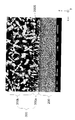
- FIG. 5 is a backscattered electron image obtained by observing the cross section of the bonded body with a scanning electron microscope (SEM).
- the manifold 200 has a surface 200S.
- FIG. 5 shows a cross section substantially perpendicular to the surface 200S.
- the surface 200S is formed to be substantially flat, but minute irregularities may be formed, or the surface 200S may be curved or bent as a whole or locally.
- the glass part 300 is joined to the surface 200S of the manifold 200.
- the glass part 300 includes an interface region 300a and an internal region 300b in a cross section perpendicular to the surface 200S of the manifold 200.
- the interface region 300a is a region within 5 ⁇ m from the surface 200S of the manifold 200.
- the internal region 300b is a region over 5 ⁇ m from the surface 200S of the manifold 200.
- the range of the internal region 300b may not be specified in particular, but as described later, in order to calculate the characteristics of the crystal grains contained in the internal region 300b, in this embodiment, the surface 200S of the manifold 200 is more than 5 ⁇ m and 100 ⁇ m. The following range is defined as the internal area 300b.
- the boundary between the interface region 300a and the internal region 300b is drawn in a substantially straight line shape, but is actually defined by a line parallel to the surface 200S of the manifold 200.
- Each of the interface region 300a and the internal region 300b is composed of a plurality of crystal grains.
- the crystal particles displayed in white, the crystal particles displayed in gray, and the crystal particles displayed in black are mixed, but the display colors are different as described above. This is because there is a minute mass difference for each crystal particle.
- each of the interface region 300a and the inner region 300b contains a plurality of rod-shaped crystal grains.
- the rod-shaped crystal particles mean crystal particles having an aspect ratio of 3 or more.
- the rod-shaped crystal grains contained in each of the interface region 300a and the internal region 300b are specified by the following method.
- a SEM manufactured by ZEISS, model ULTRA55
- a backscattered electron detector is used to acquire a backscattered electron image obtained by enlarging the cross section of the interface region 300a perpendicular to the front surface 200S of the manifold 200 by 5000 times.
- the brightest displayed particle that is, the particle displayed at the highest brightness
- an electron diffraction pattern of the brightest displayed particle is acquired by a scanning transmission electron microscope (STEM), and it is confirmed that the brightest displayed particle is a crystalline particle.
- the aspect ratio is obtained by dividing the maximum Feret diameter of the crystal particle by the minimum Feret diameter, and the rod-shaped crystal particles having an aspect ratio of 3 or more are specified.
- the maximum Feret diameter is the maximum distance between two parallel straight lines when a crystal grain is sandwiched by two parallel straight lines on the backscattered electron image.
- the minimum Feret diameter is the minimum distance between two parallel straight lines when a crystal grain is sandwiched by two parallel straight lines on the backscattered electron image.
- the average orientation angle of the rod-shaped crystal grains included in the interface region 300a is 60 degrees or more and 120 degrees or less. Therefore, the rod-shaped crystal grains included in the interface region 300a can be erected on the surface 200S of the manifold 200. Therefore, due to thermal expansion and thermal contraction of the manifold 200, cracks are likely to occur in the interface region 300a in the direction along the surface 200S, but rod-shaped crystal particles are erected on the surface 200S of the manifold 200. Therefore, it is possible to suppress the occurrence of cracks along the surface 200S.
- the average orientation angle of the rod-shaped crystal grains included in the interface region 300a is more preferably 70 degrees or more and 110 degrees or less. Thereby, it is possible to further suppress the occurrence of cracks along the surface 200S.
- the average orientation angle of the rod-shaped crystal grains contained in the inner region 300b is not particularly limited.
- rod-shaped crystal grains may be randomly arranged in the internal region 300b as compared with the interface region 300a, and the average orientation angle of rod-shaped crystal grains included in the internal region 300b is the rod-shaped crystal grains included in the interface region 300a. It may be larger or smaller than the average orientation angle of the crystal grains, or may be the same.
- the average orientation angle of rod-shaped crystal grains contained in the interface region 300a is measured by the following method. First, after the rod-shaped crystal particles are specified in the interface region 300a by the above-described method, 30 rod-shaped crystal particles are randomly selected from the interface region 300a. Next, with respect to each of the selected 30 rod-shaped crystal grains, the angle formed by the direction parallel to the two straight lines defining the minimum Feret diameter with respect to the straight line approximating the surface 200S by the least squares method is measured as the orientation angle. To do. At this time, the orientation angle is uniformly measured on one side (for example, the angle on the left side in FIG. 5) in the direction parallel to the two straight lines defining the minimum Feret diameter. Then, the average orientation angle of the rod-shaped crystal grains included in the interface region 300a is calculated by arithmetically averaging the orientation angles of the 30 rod-shaped crystal grains.
- the average orientation angle of the rod-shaped crystal grains contained in the inner region 300b is measured by the same method as the average orientation angle of the rod-shaped crystal grains contained in the interface region 300a described above.
- the standard deviation of the orientation angles of the plurality of rod-shaped crystal particles included in the inner region 300b is larger than the standard deviation of the orientation angles of the plurality of rod-shaped crystal particles included in the interface region 300a. That is, rod-shaped crystal grains are randomly arranged in the inner region 300b as compared with the interface region 300a. Therefore, even if a crack is generated in the interface region 300a due to thermal expansion and thermal contraction of the manifold 200 during operation of the cell stack 1, it is possible to suppress the crack from propagating to the external space. Therefore, it is possible to suppress the occurrence of cracks penetrating the glass part 300 and the deterioration of the sealing property.
- the standard deviation of the orientation angle of the rod-shaped crystal particles contained in the interface region 300a is obtained by calculating the standard deviation of the orientation angles of the 30 rod-shaped crystal particles selected to calculate the average orientation angle of the rod-shaped crystal particles.
- the standard deviation of the orientation angle of the rod-shaped crystal grains contained in the inner region 300b is measured by the same method as the standard deviation of the orientation angle of the rod-shaped crystal grains contained in the interface region 300a.
- the standard deviation value of the orientation angle of the rod-shaped crystal grains contained in the interface region 300a is not particularly limited, but may be 30 or less, for example.
- the standard deviation value of the orientation angle of the rod-shaped crystal grains contained in the interface region 300a is preferably 15 or less. Thereby, the orientation angles of the rod-shaped crystal grains in the interface region 300a are aligned and the strength in the direction along the surface 200S is improved, so that cracks can be further suppressed from occurring along the surface 200S. Since it is preferable that the orientation angles of the rod-shaped crystal grains included in the interface region 300a are uniform, the lower limit of the standard deviation of the orientation angle of the rod-shaped crystal grains included in the interface region 300a is not limited, but may be 5 or more, for example. it can.
- the value of the standard deviation of the orientation angle of the rod-shaped crystal grains contained in the internal region 300b is not particularly limited, but can be 40 or more, for example.
- the standard deviation value of the orientation angle of the rod-shaped crystal grains contained in the inner region 300b is preferably 50 or more. Thereby, the crack generated in the interface region 300a can be further suppressed from propagating in the inner region 300b. Since it is preferable that the orientation angle of the rod-shaped crystal particles included in the inner region 300b is more random, the upper limit value of the standard deviation of the orientation angle of the rod-shaped crystal particles included in the inner region 300b is not limited, but may be, for example, 60 or less. it can.
- the average grain size of the crystal grains contained in the interface region 300a is smaller than the average grain size of the crystal grains contained in the inner region 300b.
- the strength of the interface region 300a of the glass part 300 can be improved. Therefore, even when thermal stress due to thermal expansion and thermal contraction of the manifold is concentrated on the interface region 300a during the operation of the cell stack 1, it is possible to prevent the interface region 300a from being cracked. Further, it is not necessary to use an excessively fine seed crystal in order to form the inner region 300b, and it is possible to prevent crystallization from starting too early in the firing step of the inner region 300b.
- the average particle size of the crystal particles contained in the interface region 300a is preferably 0.8 times or less, more preferably 0.6 times or less, the average particle size of the crystal particles contained in the inner region 300b, and 0.4 or less. It is particularly preferable that the amount is not more than twice. This can further suppress the occurrence of cracks in the interface region 300a.
- the average grain size of the crystal grains contained in the interface region 300a is not particularly limited, but can be 0.2 ⁇ m or more and 2.5 ⁇ m or less.
- the average particle size of the crystal particles contained in the inner region 300b is not particularly limited, but can be 3 ⁇ m or more and 20 ⁇ m or less.
- the average grain size of the crystal grains contained in the interface region 300a is measured by the following method. First, a FE-SEM (model ULTRA55 manufactured by ZEISS) using a backscattered electron detector is used to acquire a backscattered electron image obtained by enlarging the cross section of the interface region 300a perpendicular to the front surface 200S of the manifold 200 by 5000 times. Next, on the backscattered electron image, the brightest displayed particle (that is, the particle displayed at the highest brightness) is specified. Next, an electron diffraction pattern of the brightest displayed particle is acquired by a scanning transmission electron microscope (STEM), and it is confirmed that the brightest displayed particle is a crystalline particle.
- STEM scanning transmission electron microscope
- the diameter of a circle having the same cross-sectional area as each crystal grain (hereinafter, referred to as “circle equivalent diameter") is calculated. ..
- an arithmetic average value of the equivalent circle diameters of the respective crystal grains (hereinafter referred to as “average equivalent circle diameter”) is calculated, and this average circle equivalent diameter is taken as the average grain size of the crystal grains included in the interface region 300a. ..
- the crystal particles overlapping the boundary between the interface region 300a and the internal region 300b are excluded from the measurement target of the average particle size.
- fine crystal particles having an equivalent circle diameter of 0.03 ⁇ m or less are excluded from the measurement target of the average particle size.
- the average particle size of the crystal particles contained in the internal region 300b is measured by the same method as the average particle size of the crystal particles contained in the interface region 300a described above.
- the interface region bonding material containing a rod-shaped seed crystal containing at least one element (or oxide) of Ba, Ca, Mg, Al, La, Ti, Cr, Zr, Ce, and B is used as the manifold 200.
- a region to be joined with the glass portion 300 is applied by screen printing.
- rod-shaped seed crystals are arranged so as to stand on the surface of the manifold 200.
- the size of the opening of the plate making used for screen printing it is possible to adjust the average orientation angle of the rod-shaped crystal grains and the standard deviation of the orientation angle in the interface region 300a described later.
- the smaller the opening for plate making is the larger the average orientation angle of the rod-shaped crystal particles can be.
- the smaller the opening of the plate making is, the smaller the standard deviation of the orientation angle of the rod-shaped crystal particles can be made.
- the applied bonding material for the interfacial region is dried to form a molded body of the interfacial region 300a in the glass part 300.
- the plurality of fuel cells 100 are arranged in a stack and fixed to a predetermined jig, and the base end portion 10a of each fuel cell 100 is inserted into each through hole 221 of the manifold 200.
- a bonding material for an internal region containing a rod-shaped seed crystal containing at least one element (or oxide) of Ba, Ca, Mg, Al, La, Ti, Cr, Zr, Ce, B is used as a fuel.
- the gap G between the battery cell 100 and the manifold 200 is filled with a dispenser.
- the rod-shaped seed crystal contained in the bonding material for the interface region can be arranged in random directions.
- heat treatment (750 to 900° C., 1 to 10 hours) is applied to the molded body of the glass part 300.
- the rod-shaped seed crystal arranged so as to stand on the surface of the manifold 200 grows in the direction away from the surface of the manifold 200 to become rod-shaped crystal particles. Therefore, in the interface region 300a, rod-shaped crystal grains having an average orientation angle of 60 degrees or more and 120 degrees or less are formed.
- the rod-shaped seed crystals arranged in random directions grow and become rod-shaped crystal particles. Therefore, rod-shaped crystal grains with random orientation angles grow in the inner region 300b.
- the standard deviation of the orientation angles of the rod-shaped crystal grains included in the inner region 300b is larger than the standard deviation of the orientation angles of the rod-shaped crystal grains included in the interface region 300a.
- the aspect ratio of the rod-shaped crystal grains in each of the interface region 300a and the internal region 300b can be increased as the keeping time of the heat treatment is lengthened.
- the joined body according to the present invention is applied to a cell stack including a fuel cell, but the joined body according to the present invention is an electrochemical cell such as an electrolysis cell that produces hydrogen and oxygen from water vapor. It can be applied to a cell stack including cells.
- the fuel battery cell 100 is a so-called horizontal stripe type fuel battery cell in which the plurality of power generating element portions A are arranged in the length direction of the support substrate 10.
- the configuration of 100 is not limited to this.
- the fuel cell 100 can take various forms such as a vertical stripe type, a flat plate type, and a cylindrical type.
- the “joined body” includes the manifold 200 as the “first member to be joined” joined to the glass part 300, but the invention is not limited to this.
- the “first member to be joined” may be a member other than the manifold 200.
- the “joined body” includes the fuel cell 100 as the “second joined member” joined to the glass part 300, but the invention is not limited to this.
- the “second member to be joined” may be a member other than the fuel cell 100.
- the configuration of the interface region of the glass part 300 with the fuel cell 100 may be the same as the interface region 300a or the internal region 300b. Good.
- the base end portion 10a of each fuel cell 100 is inserted into each through hole 221 of the manifold 200, but it may be arranged outside each through hole 221.
- the base end portion 10a of each fuel cell 100 is fixed to the manifold 200 via the glass seal portion 300 at a position apart from each through hole 221.
Landscapes
- Chemical & Material Sciences (AREA)
- Life Sciences & Earth Sciences (AREA)
- Engineering & Computer Science (AREA)
- Manufacturing & Machinery (AREA)
- Sustainable Development (AREA)
- Sustainable Energy (AREA)
- Chemical Kinetics & Catalysis (AREA)
- Electrochemistry (AREA)
- General Chemical & Material Sciences (AREA)
- Inorganic Chemistry (AREA)
- Fuel Cell (AREA)
Abstract
接合体は、マニホールド(200)とガラス部(300)とを備える。ガラス部(300)は、マニホールド(200)の表面(200S)から5μm以内の界面領域(300a)と、マニホールド(200)の表面(200S)から5μm超の内部領域(300b)とを含む。界面領域(300a)及び内部領域内部領域(300b)それぞれは、断面視において、3以上のアスペクト比を有する棒状結晶粒子を含む。界面領域(300a)に含まれる棒状結晶粒子の平均配向角度は、60度以上120度以下である。内部領域(300b)に含まれる棒状結晶粒子の配向角度の標準偏差は、界面領域(300a)に含まれる棒状結晶粒子の配向角度の標準偏差より大きい。
Description
本発明は、燃料電池のセルスタックに関する。
従来の燃料電池のセルスタックは、燃料電池セルと、金属によって構成されるマニホールドと、結晶化ガラスによって構成されるガラス部とを備える(特許文献1を参照)。
マニホールドは、燃料電池セルが挿入される貫通孔を有する。ガラス部は、燃料電池セルとマニホールドとを接合する。ガラス部は、マニホールドの内部空間(例えば、燃料ガスが供給される空間)と外部空間(例えば、空気が供給される空間)とを区画することによって、燃料ガスと空気との混合を防止する。
セルスタックでは、稼働時に、マニホールドの熱膨張及び熱収縮に伴う熱応力がガラス部に発生するため、ガラス部のうちマニホールドとの界面付近にクラックが発生しやすい。このクラックが、熱応力によってさらに成長すると、マニホールドの内部空間と外部空間とを繋ぐ通路が形成されて、燃料ガスと空気とが混合してしまうおそれがある。
本発明は、ガラス部にクラックが発生することを抑制可能な接合体の提供を目的とする。
本発明に係る接合体は、第1被接合部材と、第1被接合部材の表面に接合されるガラス部とを備える。ガラス部は、第1被接合部材の表面から5μm以内の界面領域と、第1被接合部材の表面から5μm超の内部領域とを含む。界面領域及び内部領域それぞれは、断面視において、3以上のアスペクト比を有する棒状結晶粒子を含む。界面領域に含まれる棒状結晶粒子の平均配向角度は、60度以上120度以下である。内部領域に含まれる棒状結晶粒子の配向角度の標準偏差は、界面領域に含まれる棒状結晶粒子の配向角度の標準偏差より大きい。
本発明によれば、ガラス部にクラックが発生することを抑制可能な接合体を提供することができる。
<セルスタックの構成>
本実施形態に係るセルスタック1の構成について、図面を参照しながら説明する。図1は、セルスタック1の全体斜視図である。図2は、燃料電池セル100の全体斜視図である。図3は、マニホールド200の全体斜視図である。図4は、燃料電池セル100及びマニホールド200の部分拡大断面図である。
本実施形態に係るセルスタック1の構成について、図面を参照しながら説明する。図1は、セルスタック1の全体斜視図である。図2は、燃料電池セル100の全体斜視図である。図3は、マニホールド200の全体斜視図である。図4は、燃料電池セル100及びマニホールド200の部分拡大断面図である。
セルスタック1は、固体酸化物形燃料電池(SOFC;Solid Oxide Fuel Cell)に用いられる構造体である。なお、本実施形態では、図1に示すように、x,y,z座標系が設定されている。
セルスタック1は、複数の燃料電池セル100と、マニホールド200と、ガラス部300とを備える。マニホールド200とガラス部300は、本発明に係る「接合体」を構成する。本発明に係る「接合体」は、燃料電池セル100を含んでいてもよい。
<燃料電池セル>
図1に示すように、各燃料電池セル100は、マニホールド200に設けられる。燃料電池セル100は、互いに間隔を隔てて並べられる。図2及び図4に示すように、燃料電池セル100のx軸方向(長手方向)において燃料ガスが流入する側の基端部10aは、ガラス部300を介してマニホールド200に接合される。燃料電池セル100は、本発明に係る「第2被接合部材」の一例である。燃料電池セル100のx軸方向において燃料ガスが排出される側の先端部10bは、自由端となっている。
図1に示すように、各燃料電池セル100は、マニホールド200に設けられる。燃料電池セル100は、互いに間隔を隔てて並べられる。図2及び図4に示すように、燃料電池セル100のx軸方向(長手方向)において燃料ガスが流入する側の基端部10aは、ガラス部300を介してマニホールド200に接合される。燃料電池セル100は、本発明に係る「第2被接合部材」の一例である。燃料電池セル100のx軸方向において燃料ガスが排出される側の先端部10bは、自由端となっている。
図2に示すように、燃料電池セル100は、実質的に平板状に形成される。燃料電池セル100の長手方向、短手方向及び厚み方向は、それぞれx軸方向、y軸方向及びz軸方向に対応する。
燃料電池セル100のx軸方向の長さL1は特に制限されないが、50mm以上500mm以下の範囲内に設定することができる。燃料電池セル100のy軸方向の長さL2は特に制限されないが、10mm以上100mm以下の範囲内に設定することができる。燃料電池セル100のz軸方向の長さL3は特に制限されないが、1mm以上5mm以下の範囲内に設定することができる。
各燃料電池セル100は、複数の発電素子部Aと、支持基板10と、シール膜20とを有する。
各発電素子部Aは、燃料極、固体電解質膜及び空気極を有する。各発電素子部Aは、燃料極、固体電解質膜及び空気極の順に積層された積層焼成体である。ここでは、燃料極は、例えば、NiO(酸化ニッケル)とYSZ(8YSZ;イットリア安定化ジルコニア)とから構成される。固体電解質膜は、例えば、YSZ(8YSZ;イットリア安定化ジルコニア)から構成される。空気極は、例えば、LSCF=(La,Sr)(Co,Fe)O3(ランタンストロンチウムコバルトフェライト)から構成される。
複数の発電素子部Aは、支持基板10に設けられる。複数の発電素子部Aは、電気的に直列に接続される。発電素子部Aの個数は特に制限されない。
支持基板10は、電子伝導性を有さない多孔質の材料から構成された焼成体である。支持基板10は、例えば、CSZ(カルシア安定化ジルコニア)で構成される。
支持基板10は、発電素子部Aを支持する。具体的には、支持基板10の両主面には、複数の発電素子部Aが、x軸方向に所定の間隔を隔てて設けられている。
支持基板10の内部には、複数の燃料ガス流路11が形成されている。各燃料ガス流路11は、x軸方向に延びている。各燃料ガス流路11は、支持基板10を貫通する。各燃料ガス流路11は、y軸方向(幅方向)に所定の間隔を隔てて形成される。
シール膜20は、支持基板10の外表面を覆う。シール膜20は、緻密質材料によって構成することができる。緻密質材料としては、例えば、YSZ、ScSZ、ガラス、スピネル酸化物などが挙げられる。シール膜20は、各発電素子部Aの固体電解質膜と同じ材料によって構成されていてもよい。この場合、シール膜20は、各発電素子部Aの固体電解質膜と一体的に形成されていてもよい。
<マニホールド>
マニホールド200は、本発明に係る「第1被接合部材」及び「金属部材」の一例である。マニホールド200は、複数の燃料電池セル100それぞれに燃料ガスを供給するための中空体である。図3及び図4に示すように、マニホールド200は、実質的に直方体状である。マニホールド200では、高さ方向、短手方向及び長手方向が、x軸方向、y軸方向及びz軸方向に対応する。
マニホールド200は、本発明に係る「第1被接合部材」及び「金属部材」の一例である。マニホールド200は、複数の燃料電池セル100それぞれに燃料ガスを供給するための中空体である。図3及び図4に示すように、マニホールド200は、実質的に直方体状である。マニホールド200では、高さ方向、短手方向及び長手方向が、x軸方向、y軸方向及びz軸方向に対応する。
図3及び図4に示すように、マニホールド200は、基部210と、支持板220とを有する。基部210は、金属材料(例えば、ステンレス鋼など)によって構成される。基部210は、底部と、底部を取り囲む側壁とを有している。底部と側壁とによって、上方に向けて開口する開口部が形成される。
支持板220は、金属材料(例えば、ステンレス鋼など)によって構成される。支持板220は、基部210上に配置される。具体的には、支持板220は、基部210の側壁の先端部に配置され、基部210の開口部を塞ぐ。このように、支持板220が基部210の開口部を塞ぐことによって、マニホールド200には、内部空間S1が形成される(図4を参照)。この内部空間S1には、燃料ガスが導入される。
燃料ガスは、導入管230を介して、外部から内部空間S1に導入される。導入管230は、金属材料(例えば、ステンレス鋼など)によって構成される。導入管230は、マニホールド200の支持板220に接合される。
マニホールド200は、図3及び図4に示すように、各燃料電池セル100を支持する。具体的には、マニホールド200の支持板220、複数の貫通孔221を有している。各貫通孔221は、マニホールド200の外側(外部空間)と内部空間S1とを連通するように、支持板220に形成されている。より具体的には、図4に示すように、各貫通孔221は、支持板220をx軸方向(高さ方向)に貫通している。図3に示すように、各貫通孔221は、z軸方向(長手方向)に所定の間隔を隔てて形成されるとともに、y軸方向(短手方向)にも所定の間隔を隔てて形成される。
図4に示すように、各貫通孔221には、各燃料電池セル100が配置される。詳細には、各燃料電池セル100の燃料ガス流路11が内部空間S1に連通するように、各貫通孔221には、各燃料電池セル100の基端部10aが挿入される。
<ガラス部>
ガラス部300は、例えば、結晶化ガラスで構成される。結晶化ガラスとしては、例えば、SiO2-B2O3系、SiO2-CaO系、MgO-B2O3系、又はSiO2-MgO系のものが用いられる。なお、結晶化ガラスとしては、SiO2-MgO系のものが最も好ましい。
ガラス部300は、例えば、結晶化ガラスで構成される。結晶化ガラスとしては、例えば、SiO2-B2O3系、SiO2-CaO系、MgO-B2O3系、又はSiO2-MgO系のものが用いられる。なお、結晶化ガラスとしては、SiO2-MgO系のものが最も好ましい。
ここで用いられる結晶化ガラスは、全体積に対する「結晶相が占める体積」の割合(結晶化度)が60%以上であり、かつ、全体積に対する「非晶質相及び不純物が占める体積」の割合が40%未満のガラスである。
ガラス部300は、マニホールド200の内部空間S1の燃料ガスと、マニホールド200の外部空間の空気との混合を防止するシール材として機能する。具体的には、図4に示すように、ガラス部300は、マニホールド200と各燃料電池セル100との間に配置され、マニホールド200と各燃料電池セル100とを接合する。ガラス部300は、マニホールド200と燃料電池セル100との隙間をシールする。これにより、ガラス部300は、内部空間S1と外部空間とを区画する。
図4に示すように、ガラス部300は、マニホールド200の各貫通孔221と各燃料電池セル100との隙間Gに充填される。
<その他の構造>
図4に示すように、セルスタック1は、集電部材400,500をさらに有する。集電部材400は、隣接する燃料電池セル100の間に設けられる。詳細には、集電部材400は、一方の燃料電池セル100の燃料極と、他方の燃料電池セル100の空気極とを電気的に直列に接続するために、隣接する燃料電池セル100の間に設けられる。集電部材400は、例えば、金属メッシュ等によって構成される。
図4に示すように、セルスタック1は、集電部材400,500をさらに有する。集電部材400は、隣接する燃料電池セル100の間に設けられる。詳細には、集電部材400は、一方の燃料電池セル100の燃料極と、他方の燃料電池セル100の空気極とを電気的に直列に接続するために、隣接する燃料電池セル100の間に設けられる。集電部材400は、例えば、金属メッシュ等によって構成される。
集電部材500は、各燃料電池セル100に設けられる。詳細には、集電部材500は、各燃料電池セル100の表側と裏側とを電気的に直列に接続するために、各燃料電池セル100に設けられている。
<接合体の構成>
次に、マニホールド200とガラス部300とによって構成される「接合体」の構成について、図面を参照しながら説明する。図5は、接合体の断面を走査型電子顕微鏡(SEM)で観察した反射電子像である。
次に、マニホールド200とガラス部300とによって構成される「接合体」の構成について、図面を参照しながら説明する。図5は、接合体の断面を走査型電子顕微鏡(SEM)で観察した反射電子像である。
マニホールド200は、表面200Sを有する。図5には、表面200Sに対して実質的に垂直な断面が図示されている。本実施形態において、表面200Sは、略平坦に形成されているが、微少な凹凸が形成されていてもよいし、全体的又は局所的に湾曲又は屈曲していてもよい。
ガラス部300は、マニホールド200の表面200Sに接合される。ガラス部300は、マニホールド200の表面200Sに垂直な断面において、界面領域300aと内部領域300bとを含む。
界面領域300aは、マニホールド200の表面200Sから5μm以内の領域である。内部領域300bは、マニホールド200の表面200Sから5μm超の領域である。内部領域300bの範囲は特に規定しなくてもよいが、後述するように、内部領域300bに含まれる結晶粒子の特性を算出する都合上、本実施形態では、マニホールド200の表面200Sから5μm超100μm以下の範囲を内部領域300bとして規定する。
なお、図5において、界面領域300aと内部領域300bとの境界は、略直線状に描かれているが、実際にはマニホールド200の表面200Sに平行な線によって規定される。
界面領域300a及び内部領域300bのそれぞれは、複数の結晶粒子によって構成される。図5の反射電子像では、白色で表示される結晶粒子と、灰色で表示される結晶粒子と、黒色で表示される結晶粒子とが混在しているが、このように表示色が異なるのは、結晶粒子ごとに微小な質量差が存在するからである。
図5に示すように、界面領域300a及び内部領域300bそれぞれには、複数の棒状結晶粒子が含まれている。本明細書において、棒状結晶粒子とは、3以上のアスペクト比を有する結晶粒子を意味する。
界面領域300a及び内部領域300bそれぞれに含まれる棒状結晶粒子は、以下の手法によって特定される。まず、反射電子検出器を用いたSEM(ZEISS社製、型式ULTRA55)によって、マニホールド200の表面200Sに対して垂直な界面領域300aの断面を5000倍で拡大した反射電子像を取得する。次に、反射電子像上において、最も明るく表示される粒子(すなわち、最高輝度で表示される粒子)を特定する。次に、最も明るく表示される粒子の電子回折パターンを走査透過電子顕微鏡(STEM)で取得して、最も明るく表示される粒子が結晶粒子であることを確認する。次に、最も明るく表示される結晶粒子それぞれについて、結晶粒子の最大フェレー径を最小フェレー径で除すことでアスペクト比を求め、アスペクト比が3以上の棒状結晶粒子を特定する。最大フェレー径は、反射電子像上において、結晶粒子を平行な2本の直線で挟んだ場合における当該2本の直線間の最大距離である。最小フェレー径は、反射電子像上において、結晶粒子を平行な2本の直線で挟んだ場合における当該2本の直線間の最小距離である。
界面領域300aに含まれる棒状結晶粒子の平均配向角度は、60度以上120度以下である。これにより、界面領域300aに含まれる棒状結晶粒子を、マニホールド200の表面200Sに対して立設させることができる。従って、マニホールド200の熱膨張及び熱収縮に伴って、界面領域300aには表面200Sに沿った方向にクラックが発生しやすいが、棒状結晶粒子がマニホールド200の表面200Sに対して立設されているため、表面200Sに沿ってクラックが発生することを抑制できる。
界面領域300aに含まれる棒状結晶粒子の平均配向角度は、70度以上110度以下であることがより好ましい。これにより、表面200Sに沿ってクラックが発生することをより抑制できる。
一方、内部領域300bに含まれる棒状結晶粒子の平均配向角度は、特に制限されない。後述するように、内部領域300bでは界面領域300aに比べて棒状結晶粒子がランダムに配置されていればよく、内部領域300bに含まれる棒状結晶粒子の平均配向角度は、界面領域300aに含まれる棒状結晶粒子の平均配向角度より大きくても小さくてもよいし、或いは同じであってもよい。
界面領域300aに含まれる棒状結晶粒子の平均配向角度は、以下の手法で測定される。まず、上述した手法により、界面領域300aにおいて棒状結晶粒子を特定した後、界面領域300aから30個の棒状結晶粒子を無作為に選出する。次に、選出した30個の棒状結晶粒子それぞれについて、最小フェレー径を規定する2本の直線に平行な方向が、表面200Sを最小二乗法で近似した直線に対して成す角度を配向角度として測定する。この際、最小フェレー径を規定する2本の直線に平行な方向の一方側(例えば、図5では左側の角度)に統一して配向角度を測定する。そして、30個の棒状結晶粒子それぞれの配向角度を算術平均することによって、界面領域300aに含まれる棒状結晶粒子の平均配向角度を算出する。
内部領域300bに含まれる棒状結晶粒子の平均配向角度は、上述した界面領域300aに含まれる棒状結晶粒子の平均配向角度と同じ手法で測定される。
内部領域300bに含まれる複数の棒状結晶粒子の配向角度の標準偏差は、界面領域300aに含まれる複数の棒状結晶粒子の配向角度の標準偏差より大きい。すなわち、内部領域300bでは界面領域300aに比べて棒状結晶粒子がランダムに配置されている。そのため、セルスタック1の稼働時に、マニホールド200の熱膨張及び熱収縮に伴って界面領域300aにクラックが発生したとしても、当該クラックが外部空間にまで進展することを抑制できる。従って、ガラス部300を貫通するクラックが発生してシール性が低下することを抑制できる。
界面領域300aに含まれる棒状結晶粒子の配向角度の標準偏差は、棒状結晶粒子の平均配向角度を算出するために選出した30個の棒状結晶粒子それぞれの配向角度の標準偏差を算出することによって得られる。
内部領域300bに含まれる棒状結晶粒子の配向角度の標準偏差は、上述した界面領域300aに含まれる棒状結晶粒子の配向角度の標準偏差と同じ手法で測定される。
界面領域300aに含まれる棒状結晶粒子の配向角度の標準偏差の値は特に制限されないが、例えば30以下とすることができる。界面領域300aに含まれる棒状結晶粒子の配向角度の標準偏差の値は、15以下であることが好ましい。これにより、界面領域300aにおける各棒状結晶粒子の配向角度が揃って、表面200Sに沿った方向の強度が向上するため、表面200Sに沿ってクラックが発生することをより抑制できる。界面領域300aに含まれる棒状結晶粒子の配向角度が揃っているほど好ましいため、界面領域300aに含まれる棒状結晶粒子の配向角度の標準偏差の下限値は制限されないが、例えば5以上とすることができる。
内部領域300bに含まれる棒状結晶粒子の配向角度の標準偏差の値は特に制限されないが、例えば40以上とすることができる。内部領域300bに含まれる棒状結晶粒子の配向角度の標準偏差の値は、50以上であることが好ましい。これにより、界面領域300aに発生したクラックが内部領域300b内に進展することをより抑制できる。内部領域300bに含まれる棒状結晶粒子の配向角度はランダムであるほど好ましいため、内部領域300bに含まれる棒状結晶粒子の配向角度の標準偏差の上限値は制限されないが、例えば60以下とすることができる。
また、図5に示すように、界面領域300aに含まれる結晶粒子の平均粒径は、内部領域300bに含まれる結晶粒子の平均粒径より小さいことが好ましい。これにより、ガラス部300のうち界面領域300aの強度を向上させることができる。そのため、セルスタック1の稼働時に、マニホールドの熱膨張及び熱収縮による熱応力が界面領域300aに集中しても、界面領域300aにクラックが発生することを抑制できる。また、内部領域300bを形成するために過剰に微細な種結晶を用いる必要がなく、内部領域300bを焼成工程において結晶化の開始が早くなりすぎることを抑制できる。そのため、内部領域300bの流れ性が低下して流動が阻害されるのを防ぐことができるので、内部領域300bの形状を容易に制御することができる。その結果、内部領域300bのシール性を向上させることができる。以上より、ガラス部300におけるクラック抑制とシール性向上とを両立させることができる。
界面領域300aに含まれる結晶粒子の平均粒径は、内部領域300bに含まれる結晶粒子の平均粒径の0.8倍以下であることが好ましく、0.6倍以下がより好ましく、0.4倍以下が特に好ましい。これによって、界面領域300aにクラックが発生することをより抑制できる。
界面領域300aに含まれる結晶粒子の平均粒径は特に制限されないが、0.2μm以上2.5μm以下とすることができる。内部領域300bに含まれる結晶粒子の平均粒径は特に制限されないが、3μm以上20μm以下とすることができる。
界面領域300aに含まれる結晶粒子の平均粒径は、以下の手法で測定される。まず、反射電子検出器を用いたFE-SEM(ZEISS社製、型式ULTRA55)によって、マニホールド200の表面200Sに対して垂直な界面領域300aの断面を5000倍で拡大した反射電子像を取得する。次に、反射電子像上において、最も明るく表示される粒子(すなわち、最高輝度で表示される粒子)を特定する。次に、最も明るく表示される粒子の電子回折パターンを走査透過電子顕微鏡(STEM)で取得して、最も明るく表示される粒子が結晶粒子であることを確認する。次に、最も明るく表示される結晶粒子を界面領域300aから無作為に30個選択して、各結晶粒子と同じ断面積を有する円の直径(以下、「円相当径」という。)を算出する。次に、各結晶粒子の円相当径の算術平均値(以下、「平均円相当径」という。)を算出し、この平均円相当径を界面領域300aに含まれる結晶粒子の平均粒径とする。ただし、結晶粒子の平均粒径を測定する際、界面領域300aと内部領域300bとの境界に重なっている結晶粒子は、平均粒径の測定対象から除外するものとする。また、結晶粒子の平均粒径を測定する際、円相当径が0.03μm以下の微細な結晶粒子は、平均粒径の測定対象から除外する。
内部領域300bに含まれる結晶粒子の平均粒径は、上述した界面領域300aに含まれる結晶粒子の平均粒径と同じ手法で測定される。
<セルスタックの組立て>
まず、Ba、Ca、Mg、Al、La、Ti、Cr、Zr、Ce、Bの少なくとも1種類の元素(又は酸化物)を含有する棒状の種結晶を含む界面領域用接合材を、マニホールド200のうちガラス部300と接合する領域にスクリーン印刷で塗布する。これにより、マニホールド200の表面に対して立設するように棒状の種結晶が配列される。この際、スクリーン印刷に用いる製版のオープニングの大きさを調整することによって、後述する界面領域300aにおける棒状結晶粒子の平均配向角度と配向角度の標準偏差とを調整することができる。例えば、製版のオープニングを小さくするほど、棒状結晶粒子の平均配向角度を大きくすることができる。また、製版のオープニングを小さくするほど、棒状結晶粒子の配向角度の標準偏差を小さくすることができる
まず、Ba、Ca、Mg、Al、La、Ti、Cr、Zr、Ce、Bの少なくとも1種類の元素(又は酸化物)を含有する棒状の種結晶を含む界面領域用接合材を、マニホールド200のうちガラス部300と接合する領域にスクリーン印刷で塗布する。これにより、マニホールド200の表面に対して立設するように棒状の種結晶が配列される。この際、スクリーン印刷に用いる製版のオープニングの大きさを調整することによって、後述する界面領域300aにおける棒状結晶粒子の平均配向角度と配向角度の標準偏差とを調整することができる。例えば、製版のオープニングを小さくするほど、棒状結晶粒子の平均配向角度を大きくすることができる。また、製版のオープニングを小さくするほど、棒状結晶粒子の配向角度の標準偏差を小さくすることができる
次に、塗布した界面領域用接合材を乾燥させることによって、ガラス部300のうち界面領域300aの成形体を形成する。
次に、複数の燃料電池セル100をスタック状に整列した状態で所定の治具に固定し、各燃料電池セル100の基端部10aをマニホールド200の各貫通孔221に挿入する。
次に、Ba、Ca、Mg、Al、La、Ti、Cr、Zr、Ce、Bの少なくとも1種類の元素(又は酸化物)を含有する棒状の種結晶を含む内部領域用接合材を、燃料電池セル100とマニホールド200との隙間Gにディスペンサで充填する。これにより、界面領域用接合材に含まれる棒状の種結晶をランダムな向きに配置させることができる。
次に、ガラス部300の成形体に熱処理(750~900℃、1~10時間)を施す。この熱処理によって、界面領域300aでは、マニホールド200の表面に対して立設するように配列された棒状の種結晶が、マニホールド200の表面から離れる方向に向かって成長して棒状結晶粒子となる。そのため、界面領域300aでは、平均配向角度が60度以上120度以下に揃った棒状結晶粒子が形成される。一方、内部領域300bでは、ランダムな向きに配置された棒状の種結晶それぞれが成長して棒状結晶粒子となる。そのため、内部領域300bでは、配向角度がランダムな棒状結晶粒子が成長する。その結果、内部領域300bに含まれる複数の棒状結晶粒子の配向角度の標準偏差は、界面領域300aに含まれる複数の棒状結晶粒子の配向角度の標準偏差より大きくなる。なお、界面領域300a及び内部領域300bそれぞれにおける棒状結晶粒子のアスペクト比は、熱処理のキープ時間を長くするほど大きくすることができる。
<他の実施形態>
以上、本発明の実施形態について説明したが、本発明はこれらに限定されるものではなく、本発明の趣旨を逸脱しない限りにおいて種々の変更が可能である。
以上、本発明の実施形態について説明したが、本発明はこれらに限定されるものではなく、本発明の趣旨を逸脱しない限りにおいて種々の変更が可能である。
(A)上記実施形態では、燃料電池セルを備えるセルスタックにおいて、本発明に係る接合体を適用したが、本発明に係る接合体は、水蒸気から水素と酸素を生成する電解セルなどの電気化学セルを備えるセルスタックに適用することができる。
(B)上記実施形態において、燃料電池セル100は、複数の発電素子部Aが支持基板10の長さ方向に配列された、いわゆる横縞型の燃料電池セルであることとしたが、燃料電池セル100の構成はこれに限定されない。燃料電池セル100は、例えば、縦縞型、平板型、円筒型など種々の形態を取りうる。
(C)上記実施形態において、本発明に係る「接合体」は、ガラス部300に接合される「第1被接合部材」としてのマニホールド200を含むこととしたが、これに限られない。「第1被接合部材」は、マニホールド200以外の部材であってもよい。
(D)上記実施形態において、本発明に係る「接合体」は、ガラス部300に接合される「第2被接合部材」として燃料電池セル100を含むこととしたが、これに限られない。「第2被接合部材」は、燃料電池セル100以外の部材であってもよい。
(E)上記実施形態では特に触れていないが、ガラス部300のうち燃料電池セル100との界面領域の構成は、界面領域300aと同様であってもよいし、内部領域300bと同様であってもよい。
(F)上記実施形態では、各燃料電池セル100の基端部10aは、マニホールド200の各貫通孔221に挿入されることとしたが、各貫通孔221の外側に配置されていてもよい。この場合、各燃料電池セル100の基端部10aは、各貫通孔221から離れた位置において、ガラスシール部300を介してマニホールド200に固定される。
1 セルスタック
100 燃料電池セル
200 マニホールド
221 貫通孔
300 ガラス部
300a 界面領域
300b 内部領域
10 支持基板
11 燃料ガス流路
A 発電素子部
100 燃料電池セル
200 マニホールド
221 貫通孔
300 ガラス部
300a 界面領域
300b 内部領域
10 支持基板
11 燃料ガス流路
A 発電素子部
Claims (3)
- 第1被接合部材と、
前記第1被接合部材の表面に接合されるガラス部と、
を備え、
前記ガラス部は、前記第1被接合部材の表面から5μm以内の界面領域と、前記第1被接合部材の表面から5μm超の内部領域とを含み、
前記界面領域及び前記内部領域それぞれは、断面視において、3以上のアスペクト比を有する棒状結晶粒子を含み、
前記界面領域に含まれる棒状結晶粒子の平均配向角度は、60度以上120度以下であり、
前記内部領域に含まれる棒状結晶粒子の配向角度の標準偏差は、前記界面領域に含まれる棒状結晶粒子の配向角度の標準偏差より大きい、
接合体。 - 前記第1被接合部材は、金属部材である、
請求項1に記載の接合体。 - 前記ガラス部を介して前記第1被接合部材に接合される第2被接合部材を備え、
前記ガラス部は、前記第1被接合部材と前記第2被接合部材との隙間をシールする、
請求項1又は2に記載の接合体。
Priority Applications (3)
| Application Number | Priority Date | Filing Date | Title |
|---|---|---|---|
| DE112019000632.0T DE112019000632B4 (de) | 2018-12-27 | 2019-09-26 | Fügestruktur |
| CN201980006588.2A CN113196534A (zh) | 2018-12-27 | 2019-09-26 | 燃料电池的电池堆 |
| US16/924,641 US10923756B2 (en) | 2018-12-27 | 2020-07-09 | Joining structure |
Applications Claiming Priority (4)
| Application Number | Priority Date | Filing Date | Title |
|---|---|---|---|
| JP2018245474 | 2018-12-27 | ||
| JP2018-245474 | 2018-12-27 | ||
| JP2019-042860 | 2019-03-08 | ||
| JP2019042860A JP6605164B1 (ja) | 2018-12-27 | 2019-03-08 | 燃料電池のセルスタック |
Related Child Applications (1)
| Application Number | Title | Priority Date | Filing Date |
|---|---|---|---|
| US16/924,641 Continuation US10923756B2 (en) | 2018-12-27 | 2020-07-09 | Joining structure |
Publications (1)
| Publication Number | Publication Date |
|---|---|
| WO2020137058A1 true WO2020137058A1 (ja) | 2020-07-02 |
Family
ID=68532193
Family Applications (1)
| Application Number | Title | Priority Date | Filing Date |
|---|---|---|---|
| PCT/JP2019/037970 Ceased WO2020137058A1 (ja) | 2018-12-27 | 2019-09-26 | 燃料電池のセルスタック |
Country Status (5)
| Country | Link |
|---|---|
| US (1) | US10923756B2 (ja) |
| JP (1) | JP6605164B1 (ja) |
| CN (1) | CN113196534A (ja) |
| DE (1) | DE112019000632B4 (ja) |
| WO (1) | WO2020137058A1 (ja) |
Families Citing this family (2)
| Publication number | Priority date | Publication date | Assignee | Title |
|---|---|---|---|---|
| JP7817325B2 (ja) * | 2024-07-02 | 2026-02-18 | 森村Sofcテクノロジー株式会社 | シール構造体、および電気化学反応セルスタック |
| JP7875912B2 (ja) * | 2024-09-13 | 2026-06-18 | 森村Sofcテクノロジー株式会社 | シール構造体、および電気化学反応セルスタック |
Citations (3)
| Publication number | Priority date | Publication date | Assignee | Title |
|---|---|---|---|---|
| JP2016042457A (ja) * | 2014-08-14 | 2016-03-31 | 日本碍子株式会社 | 燃料電池のスタック構造体 |
| JP2017045701A (ja) * | 2015-08-29 | 2017-03-02 | 京セラ株式会社 | セルスタック装置、モジュールおよびモジュール収容装置 |
| WO2018097174A1 (ja) * | 2016-11-22 | 2018-05-31 | 日本特殊陶業株式会社 | 電気化学反応単位、電気化学反応セルスタック、および、電気化学反応単位の製造方法 |
Family Cites Families (9)
| Publication number | Priority date | Publication date | Assignee | Title |
|---|---|---|---|---|
| JP4325924B2 (ja) | 2003-09-22 | 2009-09-02 | 京セラ株式会社 | 燃料電池 |
| JP2009123356A (ja) * | 2007-11-12 | 2009-06-04 | Toyota Motor Corp | 膜・電極接合体の製造方法及び膜・電極接合体 |
| EP2369661A1 (en) * | 2008-12-24 | 2011-09-28 | NGK Insulators, Ltd. | Plate-shaped particles for positive electrode active material of lithium secondary batteries, and lithium secondary batteries |
| CN103583087B (zh) * | 2011-06-08 | 2017-05-24 | 京瓷株式会社 | 电路基板以及具备该电路基板的电子装置 |
| DE102013007703A1 (de) | 2013-05-03 | 2014-11-06 | Forschungszentrum Jülich GmbH | Verfahren zur Herstellung einer Glaslot-Gründichtung |
| DE102013009001A1 (de) | 2013-05-24 | 2014-11-27 | Friedrich-Schiller-Universität Jena | Kristallisierende, cristobalitfreie und elektrisch gut isolierende Glaslote mit hohen thermischen Ausdehnungskoeffizienten zum Fügen von Metallen und/oder Keramiken |
| JP5599956B1 (ja) * | 2013-07-10 | 2014-10-01 | 日本碍子株式会社 | 燃料電池のスタック構造体 |
| CN106104892B (zh) * | 2014-03-26 | 2019-07-19 | 京瓷株式会社 | 单电池堆装置、组件及组件收纳装置 |
| WO2017073419A1 (ja) * | 2015-10-30 | 2017-05-04 | 日本電気硝子株式会社 | 結晶性ガラス封止材 |
-
2019
- 2019-03-08 JP JP2019042860A patent/JP6605164B1/ja active Active
- 2019-09-26 CN CN201980006588.2A patent/CN113196534A/zh active Pending
- 2019-09-26 DE DE112019000632.0T patent/DE112019000632B4/de active Active
- 2019-09-26 WO PCT/JP2019/037970 patent/WO2020137058A1/ja not_active Ceased
-
2020
- 2020-07-09 US US16/924,641 patent/US10923756B2/en active Active
Patent Citations (3)
| Publication number | Priority date | Publication date | Assignee | Title |
|---|---|---|---|---|
| JP2016042457A (ja) * | 2014-08-14 | 2016-03-31 | 日本碍子株式会社 | 燃料電池のスタック構造体 |
| JP2017045701A (ja) * | 2015-08-29 | 2017-03-02 | 京セラ株式会社 | セルスタック装置、モジュールおよびモジュール収容装置 |
| WO2018097174A1 (ja) * | 2016-11-22 | 2018-05-31 | 日本特殊陶業株式会社 | 電気化学反応単位、電気化学反応セルスタック、および、電気化学反応単位の製造方法 |
Also Published As
| Publication number | Publication date |
|---|---|
| CN113196534A (zh) | 2021-07-30 |
| DE112019000632T5 (de) | 2020-10-29 |
| JP6605164B1 (ja) | 2019-11-13 |
| DE112019000632B4 (de) | 2024-05-29 |
| US20200343574A1 (en) | 2020-10-29 |
| US10923756B2 (en) | 2021-02-16 |
| JP2020107590A (ja) | 2020-07-09 |
Similar Documents
| Publication | Publication Date | Title |
|---|---|---|
| JP6756027B1 (ja) | セルスタック | |
| JP2016171064A (ja) | 燃料電池のスタック構造体 | |
| JP6605164B1 (ja) | 燃料電池のセルスタック | |
| JP6876768B2 (ja) | 接合体 | |
| JP6419382B1 (ja) | セルスタック装置 | |
| JP6043455B1 (ja) | 燃料電池のスタック構造体 | |
| JP6732070B2 (ja) | 燃料電池のセルスタック | |
| JP6599696B2 (ja) | セルスタック装置、モジュールおよびモジュール収容装置 | |
| JP5985770B2 (ja) | 燃料電池のスタック構造体 | |
| JP6134048B1 (ja) | マニホールド、及び燃料電池のスタック構造体 | |
| JP2018092919A (ja) | セルスタック | |
| JP6789367B2 (ja) | セルスタック | |
| JP2019061910A (ja) | 燃料電池セル及びセルスタック装置 | |
| JP2020043046A (ja) | 合金部材、セルスタック及びセルスタック装置 | |
| JP6483319B1 (ja) | セルスタック装置 | |
| JP6605109B1 (ja) | 燃料電池セル及びセルスタック装置 | |
| JP6467002B2 (ja) | セルスタック装置 | |
| JP6043456B1 (ja) | 燃料電池のスタック構造体 | |
| JP6608085B1 (ja) | 電気化学セルスタック | |
| JP6608084B1 (ja) | 電気化学セルスタック | |
| JP2019216077A (ja) | セルスタック | |
| JP2020072077A (ja) | セルスタック装置 | |
| JP6480064B1 (ja) | マニホールド及びセルスタック装置 | |
| JP5883537B1 (ja) | 燃料電池のスタック構造体 | |
| JP6348558B2 (ja) | マニホールド |
Legal Events
| Date | Code | Title | Description |
|---|---|---|---|
| 121 | Ep: the epo has been informed by wipo that ep was designated in this application |
Ref document number: 19905915 Country of ref document: EP Kind code of ref document: A1 |
|
| 122 | Ep: pct application non-entry in european phase |
Ref document number: 19905915 Country of ref document: EP Kind code of ref document: A1 |