WO2020136968A1 - 掘削ツール交換装置およびトンネル掘進機 - Google Patents
掘削ツール交換装置およびトンネル掘進機 Download PDFInfo
- Publication number
- WO2020136968A1 WO2020136968A1 PCT/JP2019/030075 JP2019030075W WO2020136968A1 WO 2020136968 A1 WO2020136968 A1 WO 2020136968A1 JP 2019030075 W JP2019030075 W JP 2019030075W WO 2020136968 A1 WO2020136968 A1 WO 2020136968A1
- Authority
- WO
- WIPO (PCT)
- Prior art keywords
- guide member
- face
- tool
- gate plate
- inner guide
- Prior art date
- Legal status (The legal status is an assumption and is not a legal conclusion. Google has not performed a legal analysis and makes no representation as to the accuracy of the status listed.)
- Ceased
Links
Images
















Classifications
-
- E—FIXED CONSTRUCTIONS
- E21—EARTH OR ROCK DRILLING; MINING
- E21D—SHAFTS; TUNNELS; GALLERIES; LARGE UNDERGROUND CHAMBERS
- E21D9/00—Tunnels or galleries, with or without linings; Methods or apparatus for making thereof; Layout of tunnels or galleries
- E21D9/06—Making by using a driving shield, i.e. advanced by pushing means bearing against the already placed lining
- E21D9/08—Making by using a driving shield, i.e. advanced by pushing means bearing against the already placed lining with additional boring or cutting means other than the conventional cutting edge of the shield
- E21D9/087—Making by using a driving shield, i.e. advanced by pushing means bearing against the already placed lining with additional boring or cutting means other than the conventional cutting edge of the shield with a rotary drilling-head cutting simultaneously the whole cross-section, i.e. full-face machines
-
- E—FIXED CONSTRUCTIONS
- E21—EARTH OR ROCK DRILLING; MINING
- E21D—SHAFTS; TUNNELS; GALLERIES; LARGE UNDERGROUND CHAMBERS
- E21D9/00—Tunnels or galleries, with or without linings; Methods or apparatus for making thereof; Layout of tunnels or galleries
- E21D9/10—Making by using boring or cutting machines
- E21D9/11—Making by using boring or cutting machines with a rotary drilling-head cutting simultaneously the whole cross-section, i.e. full-face machines
Definitions
- the present invention relates to an excavating tool exchanging device and a tunnel machine, and more particularly to a technique for exchanging excavating tools detachably provided on a cutter head.
- an excavating tool exchanging device for exchanging excavating tools of a tunnel machine.
- Such an excavating tool changing device is disclosed, for example, in Japanese Patent No. 3589653.
- a cutter bit In the above-mentioned Japanese Patent No. 3589653, a cutter bit, a guide portion for slidably supporting the cutter bit to the side opposite to the cutting face, a through hole for penetrating when the cutter bit is projected from the cutter face plate, and the cutting bit for the non-cut face
- a slide gate having a gate lid that closes the opening on the front side of the cutter bit in the state of being slid to the side and a guide member for guiding the slide gate are provided, and the guide member slides around the opening when the slide gate slides.
- a cutter bit exchanging device provided with a seal member for sealing between the gate and the gate is disclosed. The cutter bit is held inserted in the guide case and the guide lid.
- a guide member is formed by the slide gate guide portion of the guide case and the guide portion lid of the guide lid.
- the seal member is provided in a groove formed in the guide case and the guide lid.
- the seal member between the guide member and the slide gate slides on the slide gate.
- the seal member may be damaged by sliding with a slide gate or by sand and sand that enter during sliding.
- the seal member is damaged, not only the sealing performance is deteriorated, but also the seal member is disengaged when sliding with the slide gate, and the seal member is caught in the gap between the moving slide gate and the guide member, resulting in malfunction. there is a possibility. Therefore, it is preferable that the seal member can be replaced before the damage of the seal member progresses.
- the present invention has been made to solve the above problems, and an object of the present invention is to easily replace a seal member for suppressing the inflow of earth and sand or muddy water when excavating tools. It is an object of the present invention to provide an excavating tool changing device and a tunnel machine.
- the excavation tool exchanging device is an excavating tool exchanging device for a tunnel excavator having a rotating cutter head, in which an excavating tool is disposed on the front surface, Possible excavating tool, a front plate having an opening through which the excavating tool passes by opening on the face side of the cutter head, a guide portion that supports the excavating tool so that the excavating tool can move forward and backward through the opening, and the front plate and the guide And a gate plate configured to be slidable along the front plate between the parts and opening and closing the opening, and the guide part includes an inner guide member for guiding the forward and backward movement of the drilling tool, and an inner guide member.
- a first seal member that includes an outer guide member that is movably supported on the face side and the face side opposite to the face side, and that is in contact with the gate plate from the side opposite the face face is provided at the face side end portion of the inner guide member.
- the term "tunnel machine” is a broad concept including a shield machine used in a shield method, a machine used in a propulsion method, and a tunnel boring machine used in a mountain tunnel method.
- a shield machine is a device that assembles segments while counteracting earth pressure and mud pressure from the ground by a body and a cutter head, and obtains a propulsion reaction force from the assembled segment to excavate.
- the propulsion method is a method of advancing the excavator by adding a tunnel wall (concrete or steel pipe) at the starting part along with excavation and pushing it in.
- the tunnel boring machine is a device that is mainly used for excavating relatively hard ground such as bedrock and does not have a face retaining function to counter earth pressure and mud pressure and excavates a tunnel.
- the “cutting face side” is the side on which the ground excavated by the cutter head is located, and may be rephrased as the front side in the excavation direction.
- the "counter face side” is the side opposite to the face side (pit side), and may be restated as the rear side in the excavation direction.
- the excavation tool is a tool provided on the front surface of the cutter head for excavating earth and sand, and is a concept including a cutter bit, a roller bit, and the like.
- the excavating tool exchanging device by configuring as described above, by moving the inner guide member to the non-face side along the outer guide member, the face end portion of the inner guide member is provided. It is possible to perform the replacement work of the first seal member by exposing the first seal member provided on the outer peripheral guide member to the side opposite to the face. That is, by pulling out the inner guide member from the inner and outer double guide members, the first seal member can be replaced without disassembling the entire excavation tool replacement device. This makes it possible to easily replace the seal member for suppressing the inflow of earth and sand or muddy water when exchanging the excavating tool.
- the first seal member due to the movement of the inner guide member to the side opposite to the face, the first seal member is in a non-contact state in which it is separated from the gate plate, or the first seal member is in contact with the gate plate with a weaker pressing force than during sealing.
- the gate plate can be moved in this state.
- the inner guide member After the gate plate is moved, the inner guide member is moved toward the face to bring the first seal member into close contact with the gate plate, so that the sealing property can be ensured.
- the first seal member not only can the first seal member be easily replaced, but also the wear of the first seal member can be suppressed and the number of seal replacements can be reduced.
- the excavating tool further includes a second seal member that seals the opening in a state in which the excavating tool is arranged at a projecting position on the face of the cutter head through the opening.
- the inner guide member is configured such that the inner guide member can be pulled out by moving from the outer guide member to the face opposite to the face while the excavating tool is still arranged at the protruding position.
- the inner guide member can be pulled out and the first seal member can be replaced while the opening is being sealed by the second seal member while the excavating tool is arranged at the protruding position. With this, when the inner guide member is moved to the side opposite to the face, the first seal member can be easily replaced with the excavation tool placed in the projecting position without performing work for ensuring the seal of the opening. ..
- the excavating tool exchanging device further includes a fixing member that fixes the inner guide member to the outer guide member, and the inner guide member is relieved from being fixed to the outer guide member by the fixing member.
- a fixing member that fixes the inner guide member to the outer guide member, and the inner guide member is relieved from being fixed to the outer guide member by the fixing member.
- the "fixing member” is a concept including bolts (screws), pins, keys, and the like. According to the above structure, when the gate plate is moved, the fixed state of the inner guide member can be relaxed, and the inner guide member can be moved a predetermined distance to the non-facet side.
- the first seal member By moving the inner guide member to the face opposite to the face, the first seal member is moved away from the gate plate, or the gate plate is moved while the first seal member is in contact with the gate plate with a weaker pressing force than during sealing. Can be made. As a result, it is possible to suppress the wear of the first seal member due to the sliding movement of the gate plate. After the gate plate has moved to the closed position, the inner guide member is moved to the face of the face to bring the first seal member into close contact with the gate plate, and the inner guide member is fixed. The sealing property can be secured.
- the gate plate has an inclined surface that is inclined toward the face of the face in a direction of closing the opening, and the gate plate is inclined at the closed position where the opening closes the opening.
- the surface is configured to be in close contact with the first seal member. That is, the inclined surface is inclined so as to move away from the first seal member as it goes in the direction of closing the opening. According to this structure, the seal is ensured by the contact between the inclined surface and the sealing surface (the surface on which the first sealing member is arranged) inclined according to the inclined surface.
- the excavating tool exchanging device further includes a gate guide part that guides a sliding movement of the gate plate, and the gate guide part is located before the closed position where the gate plate closes the opening part. Is configured to be guided in a direction to be pressed against the first seal member.
- the first seal member is moved away from the gate plate, or the gate plate is moved to the vicinity of the closed position while the first seal member is in contact with the gate plate with a weaker pressing force than during sealing. be able to.
- the gate guide portion guides the gate plate to the first seal member side, so that the gate plate and the first seal member start to come into close contact with each other.
- the gate plate and the first seal member may not be in contact with each other or the pressing force of the gate plate against the first seal member may be weakened. it can. As a result, it is possible to suppress wear of the first seal member due to sliding when the gate plate is opened and closed.
- a tunnel machine includes a cutter head having an excavating tool arranged on a front surface thereof, a cutter driving unit for rotating the cutter head, and an excavating tool exchanging device for exchangingly supporting the excavating tool.
- the excavating tool exchanging device includes a detachable excavating tool, a front plate having an opening on the face of the cutter head through which the excavating tool passes, and supports the excavating tool so that it can move back and forth through the opening. And a gate plate that is configured to be slidable along the front plate between the front plate and the guide unit and that opens and closes the opening.
- the guide unit guides the forward and backward movement of the drilling tool.
- a first contact member that includes an inner guide member and an outer guide member that movably supports the inner guide member toward the face and the face opposite to the face, and is in close contact with the gate plate at the face end of the inner guide member from the face opposite to the face.
- a seal member is provided.
- the inner guide member is moved along the outer guide member to the face opposite to the face, so that the end face of the face of the inner guide member is cut.
- the provided first seal member can be exposed from the outer guide member to the side opposite to the face, and the replacement work of the first seal member can be performed. This makes it possible to easily replace the seal member for suppressing the inflow of earth and sand or muddy water when exchanging the excavating tool.
- the opening can be closed by moving the gate plate in a state where the inner guide member is moved to the side opposite to the face, so that the first plate caused by sliding when the gate plate moves. Wear of the seal member can be suppressed.
- the first seal member not only can the first seal member be easily replaced, but also the wear of the first seal member can be suppressed and the number of seal replacements can be reduced.
- FIGS. 1 to 6 A tunnel excavator 1 and an excavation tool changer 100 according to a first embodiment of the present invention will be described with reference to FIGS. 1 to 6.
- the tunnel machine 1 is a shield machine
- the tunnel excavator 1 includes a tubular body 2, a cutter head 3, a cutter driving unit 4, and an excavating tool exchanging device 100.
- Fig. 1 illustrates a medium to large diameter type shield machine with an intermediate support method as the support method for the cutter head 3.
- the cutter head 3 is attached to a circularly driven support member 5 that is rotationally driven, via a cutter column 6.
- the cutter column 6 is a leg that connects the support member 5 and the cutter head 3.
- the support member 5 is rotatably supported by a swivel bearing 8 provided on a partition wall (bulk head) 7 of the front body portion 2a described later.
- the tunnel machine 1 excavates in the left direction (X1 direction) in FIG.
- the left side with respect to the cutter head 3 is the face of the tunnel under excavation
- the right side is the face opposite to the face of the tunnel (hole side).
- the front-rear direction of the excavation direction is the X direction
- the front of the excavation direction (the cutting face side) is the X1 direction
- the rear of the excavation direction (the opposite face) is the X2 direction.
- simply front and front means the front in the excavation direction (X1 direction, cutting face side)
- rear and rear means the rear in the excavation direction (X2 direction, non-face cutting side).
- the body 2 of the tunnel machine 1 includes a front body portion 2a and a rear body portion 2b.
- the body 2 is divided into a front body 2a on the front side in the excavation direction and a rear body 2b on the rear side.
- the front body portion 2a and the rear body portion 2b are formed, for example, in a cylindrical shape.
- the front body portion 2a is closed on the front side in the excavation direction by a partition wall 7, and holds the cutter head 3 at the position of the front end surface of the front body portion 2a via a swivel base bearing 8 provided on the partition wall 7. ing.
- the rear body portion 2b is connected to the rear end portion of the front body portion 2a in the excavation direction.
- the cutter head 3 is configured to rotate around the central axis A.
- the cutter head 3 is formed in a shape corresponding to the end surface shape of the front body portion 2a when viewed from the excavation direction. That is, the cutter head 3 is formed in a circular shape when viewed from the excavation direction.
- the cutter head 3 includes a spoke portion 9 extending in the radial direction from the central axis A.
- the spoke portion 9 is a hollow cylindrical beam member linearly provided in the radial direction.
- the ends of the spokes 9 on the center side are connected to a hollow center shaft 10 extending along the central axis A.
- the front surface member 9 a of the spoke portion 9 constitutes a part of the front surface 3 a of the cutter head 3.
- the cutter column 6 is connected to the rear surface member 9b of the spoke portion 9.
- An excavation tool 20 is arranged on the front surface 3 a of the cutter head 3.
- the excavation tool 20 is provided so as to project from the front surface 3a of the cutter head 3 forward (toward the cutting face).
- the excavation tool 20 is a tool for excavating the natural ground as the cutter head 3 rotates.
- the excavation tool 20 is composed of, for example, a cutter bit or a disc cutter.
- the excavation tool 20 is detachably attached to the excavation tool exchanging device 100.
- the excavation tool changing device 100 is installed on the cutter head 3 so as to hold the excavation tool 20 on the front surface 3 a of the cutter head 3.
- the excavation tool changer 100 supports the excavation tool 20 in a replaceable manner.
- the excavation tool changing device 100 is installed inside the hollow spoke portion 9.
- the excavation tool changing device 100 is fixed to the front surface member 9 a of the spoke portion 9 from the inside of the spoke portion 9.
- the excavation tool exchanging device 100 can hold the excavation tool 20 at the protruding position P that protrudes toward the face of the cutter head 3 from the front surface 3a during excavation.
- the excavation tool exchanging device 100 is configured such that the excavation tool 20 can be removed by retracting the excavation tool 20 to the inside of the spoke portion 9 on the face opposite to the face 3a of the cutter head 3.
- the excavating tool exchanging device 100 allows exchanging the excavating tool 20 inside the spoke portion 9. Details of the excavation tool changer 100 will be described later.
- the cutter column 6 is a beam member having a hollow cylindrical shape.
- the cutter column 6 supports the cutter head 3 and rotates together with the cutter head 3.
- the cutter column 6 has one end attached to the cutter head 3 and the other end attached to the annular support member 5.
- the support member 5 is rotatably supported by the swivel bearing 8. As a result, the cutter head 3 is supported by the swivel bearing 8 so as to be rotatable about the central axis A.
- the cutter driving unit 4 rotates the cutter head 3.
- the cutter drive unit 4 includes, for example, a hydraulic motor.
- the cutter head 3 is rotationally driven around the central axis A by applying a drive torque to the support member 5 through the swivel bearing by the cutter drive unit 4.
- the excavated soil scraped by the excavation tool 20 enters the chamber 11 inside the cutter head 3.
- the chamber portion 11 is a space surrounded by the cutter head 3, the peripheral wall of the front body portion 2 a and the partition wall 7.
- the excavated soil in the chamber portion 11 is conveyed to the inside of the body 2 through the partition wall 7 by the soil discharging device 12 and then discharged to the outside of the tunnel.
- the amount of excavated soil in the chamber 11 is controlled by the soil discharging device 12 to generate mud pressure in the chamber 11.
- the mud pressure in the chamber 11 is maintained by the soil discharging device 12 so as to be approximately in equilibrium with the earth pressure component of the force acting on the cutter head 3 from the natural ground side (pressure due to the soil forming the natural rock). ..
- the tunnel machine 1 includes a propulsion jack 13.
- the propulsion jack 13 pushes a segment (not shown) to propel the body 2 (the front body portion 2a and the rear body portion 2b) and the shield jack 13a, and transmits the load from the rear body portion 2b to the front body portion 2a. It includes a center-folded jack 13b.
- the tunnel machine 1 is propelled forward by the propulsive force of these propulsion jacks 13 in the excavation direction.
- the tunnel machine 1 includes an erector (not shown).
- the erector is a device that assembles segments (not shown) into a ring shape.
- the segments assembled in a ring form the wall surface of the tunnel constructed by the tunnel machine 1.
- the tunnel machine 1 excavates while constructing a tunnel wall surface by repeating excavation of a predetermined distance and assembly of segments in a state where the excavation is stopped.
- center shaft 10 penetrates the partition wall 7 and is connected to the inside of the body 2.
- the inside of the body 2, the inside of the center shaft 10 and the inside of the spokes 9 on the rear side of the partition wall 7 are at atmospheric pressure.
- an operator can perform an operation on the excavation tool exchanging device 100 through the inside of the center shaft 10 and the inside of the spokes 9.
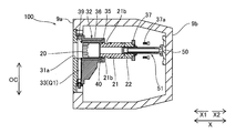
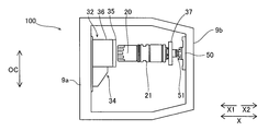
- the excavation tool changer 100 mainly includes a front plate 31, a guide portion 32, and a gate plate 33.
- the excavation tool changing device 100 includes a tool holder 21 to which the excavation tool 20 is detachably attached.
- the excavation tool changing device 100 includes a housing 34 that houses the front plate 31 and the gate plate 33.
- the guide portion 32 includes an inner guide member 35 and an outer guide member 36.
- the front plate 31 is a flat member provided so as to be exposed at the front surface 3 a of the cutter head 3.
- the front plate 31 is provided so as to fit into the opening formed in the front member 9 a of the spoke portion 9.
- the front plate 31 constitutes a part of the front surface 3 a of the cutter head 3.
- the front plate 31 has an opening 31a which is open to the face of the cutter head 3 and through which the excavation tool 20 passes.
- the opening 31a penetrates the front plate 31 in the thickness direction.
- the opening 31a allows the excavation tool 20 to pass through when the excavation tool 20 is placed at the protruding position P and when the excavation tool 20 is pulled in when the excavation tool 20 is replaced.
- the opening 31a has an opening shape corresponding to the outer shape of the drilling tool 20 so that the drilling tool 20 can pass through.
- the drilling tool 20 is attached to the tip of a cylindrical tool holder 21.
- the tool holder 21 is disposed in the guide portion 32 (inner guide member 35) with the excavation tool 20 facing the face of the face (front side).
- the guide portion 32 supports the tool holder 21 provided with the excavation tool 20 so as to be movable back and forth in the front-rear direction. Accordingly, the guide portion 32 supports the excavation tool 20 so as to be able to move back and forth through the opening 31a.
- a cylindrical extension holder 22 is connected to the rear end of the tool holder 21 by an extension bolt 23.
- the extension holder 22 is composed of two members each having a semi-cylindrical shape, and can be separated into halves.
- the housing 34 is provided so as to cover the rear surface of the front plate 31 (side surface opposite to the face).
- the housing 34 has a gate housing portion 34 a that covers the rear surface of the front plate 31.
- the gate housing portion 34a extends along the front plate 31.
- the recess 34b of the gate accommodating portion 34a is formed in a shape that allows the gate plate 33 to move between an open position Q1 (see FIG. 3) and a closed position Q2 (see FIG. 3).
- the rectangular gate plate 33 linearly moves in the OC direction between an open position Q1 that does not cover the opening 31a and a closed position Q2 that covers the opening 31a.
- the recess 34b is formed in a rectangular shape according to the moving distance of the gate plate 33 when viewed from the excavation direction.
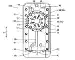
- a gate guide portion 34c is provided on each of a pair of inner side surfaces of the recess 34b extending along the OC direction.
- the gate guide portion 34c is configured to guide the sliding movement of the gate plate 33.
- the gate guide portion 34c is, for example, a groove portion extending in the OC direction.
- the side end surface of the gate plate 33 is arranged in the gate guide portion 34c, and both ends of the gate plate 33 are guided in the OC direction in the gate guide portion 34c.
- the housing 34 is provided with an outer guide member 36 that constitutes the guide portion 32.
- the outer guide member 36 is a cylindrical guide tube, and the end face on the face side is connected to the rear surface of the gate accommodating portion 34a.
- the outer guide member 36 has a shape in which the peripheral portion of the through hole is cylindrically extended rearward (opposite to the face).
- the housing 34 has the gate accommodating portion 34a and the outer guide member 36 which are integrated with each other by welding or the like. Further, the housing 34 is provided with a reinforcing rib 34d for fixing the gate accommodating portion 34a and the outer guide member 36 to each other.
- the outer guide member 36 supports the inner guide member 35 so that the inner guide member 35 can move toward the face and the face opposite to the face (in the front-rear direction). That is, the inner guide member 35 is arranged on the inner peripheral portion of the outer guide member 36.
- the inner guide member 35 is a cylindrical guide tube.
- the inner guide member 35 has a tubular portion having an outer diameter that substantially matches the inner diameter of the outer guide member 36.
- the tubular portion of the inner guide member 35 is slidably inserted in the outer guide member 36 in the front-rear direction.
- the inner guide member 35 is configured such that it can be pulled out by moving from the outer guide member 36 to the side opposite to the cutting face while the excavation tool 20 is still arranged at the protruding position P.
- the inner guide member 35 is configured to guide the forward/backward movement of the excavation tool 20.
- the inner guide member 35 supports the tool holder 21 to which the excavation tool 20 is attached at its tip so as to be slidable in the front-rear direction.
- the inner diameter of the inner guide member 35 is substantially equal to the inner diameter of the opening 31a.
- the outer diameter of the excavation tool 20 substantially matches the inner diameters of the inner guide member 35 and the opening 31a. Therefore, the excavation tool 20 can be arranged at the projecting position P by sliding the tool holder 21 inside the inner guide member 35 toward the face of the face.
- the protruding position P is a position where the excavating tool 20 protrudes toward the face of the cutter head 3 (face closer to the face than the front plate 31) through the opening 31a.
- the excavation tool 20 can be retracted by sliding the tool holder 21 in the inner guide member 35 to the side opposite to the face. Thereby, the excavation tool 20 can be exchanged by pulling the excavation tool 20 together with the tool holder 21
- a flange portion 35a extending outward in the radial direction is provided at the rear end portion (the end portion opposite to the cutting face) of the inner guide member 35.
- the flange portion 35a overlaps with the rear end portion of the outer guide member 36.
- the inner guide member 35 is fixed to the outer guide member 36 by a fixing member 38 that penetrates the flange portion 35a in the front-rear direction and is attached to the outer guide member 36.
- the fixing member 38 is a bolt (screw) that fixes the inner guide member 35 to the outer guide member 36.
- a plurality of fixing members 38 are provided along the circumferential direction of the flange portion 35a.
- the fixing member 38 is fastened to the screw hole formed at the rear end of the outer guide member 36 through the through hole of the flange portion 35a.
- the inner guide member 35 is fixed to the outer guide member 36 by a fixing member 38.
- the fixing member 38 penetrates the flange portion 35a from the side opposite to the cutting face and is fastened to the outside guide member 36 on the cutting face side.
- the inner guide member 35 is configured to be movable by a predetermined distance while being connected to the outer guide member 36 via the fixing member 38 by relaxing the fixed state of the inner guide member 35 to the outer guide member 36. Has been done.
- the inner guide member 35 can move to the non-face face side by the amount of movement of the fixing member 38 to the face face side.
- the fixing member 38 is removed, the fixed state of the inner guide member 35 is released.
- the fixed state is released, the inner guide member 35 is moved toward the face opposite to the outer guide member 36 and can be pulled out from the outer guide member 36.
- a fixing flange 37 is attached to the rear end surface (the end surface on the side opposite to the face) of the inner guide member 35 by a bolt 37a (see FIG. 5).
- the fixing flange 37 is formed so as to straddle the rear end surface of the inner guide member 35 and the rear end surface of the extension holder 22.
- the fixed flange 37 is connected to the rear end surface of the extension holder 22 by a bolt 37b.
- the fixing flange 37 fixes the tool holder 21 inside the inner guide member 35 so as not to move in the front-rear direction.
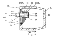
- a first seal member 39 that is in close contact with the gate plate 33 from the non-face side is provided at the face side end of the inner guide member 35.
- the first seal member 39 is annularly provided along the end face of the cylindrical inner guide member 35 on the face side.
- the first seal member 39 is made of, for example, an O ring.
- the first seal member 39 is configured to seal between the gate plate 33 and the inner guide member 35 by contacting the gate plate 33 at the closed position Q2 in the front-rear direction. This prevents muddy water or the like from entering the inside (spokes 9) of the gate plate 33 through the opening 31a in the state where the gate plate 33 is arranged at the closed position Q2.
- the excavation tool exchanging device 100 includes the second seal member 40 that seals the opening 31a in a state where the excavation tool 20 is disposed at the face P of the cutter head 3 through the opening 31a. ing.
- the second seal member 40 is provided in a circumferential shape (annular shape) along the outer peripheral surface of the tool holder 21.
- the tool holder 21 has a fitting portion 21a that fits into the opening 31a in a state where the excavation tool 20 is arranged at the protruding position P.
- the second seal member 40 is arranged on the outer peripheral surface of the fitting portion 21a. Therefore, when the excavation tool 20 is arranged at the projecting position P, the second seal member 40 seals between the outer peripheral surface of the tool holder 21 (fitting portion 21a) and the inner peripheral surface of the opening 31a.
- the second seal member 40 is provided on the outer peripheral surface of the tool holder 21, not on the inner peripheral surface of the opening 31a, when the tool holder 21 is pulled out from the guide portion 32 when excavating the excavating tool 20, The second seal member 40 can be replaced.
- the gate plate 33 is arranged between the front plate 31 and the gate accommodating portion 34a of the housing 34 (inside the recess 34b). Further, the gate plate 33 is arranged at a position between the front plate 31 and the inner guide member 35 in the front-rear direction.
- the gate plate 33 has a flat plate shape extending along the front plate 31.
- the gate plate 33 of the first embodiment has a flat plate shape having a substantially constant thickness in the excavation direction.
- the gate plate 33 has a rectangular shape when viewed from the excavation direction (see FIG. 3 ).
- the gate plate 33 may have any shape as long as it can close the opening 31a.
- the gate plate 33 is configured to linearly move in the OC direction within the gate accommodating portion 34a.
- the gate plate 33 is provided with a hole 33a extending in the OC direction.
- a screw shaft 41 is arranged in the hole 33a.
- the screw shaft 41 meshes with the nut portion 33b fixed to the gate plate 33 at the entrance of the hole 33a.
- the gate plate 33 moves.
- the gate plate 33 (see FIG. 3) linearly moves between the open position Q1 which is one end in the OC direction and the closed position Q2 which is the other end in the OC direction.
- the screw shaft 41 is rotatably attached to the housing 34. That is, the screw shaft 41 projects outward from the end of the gate accommodating portion 34 a and is held by the cover 42.
- the operator rotates the end of the screw shaft 41 protruding from the cover 42 to move the gate plate 33.
- the gate plate 33 is arranged such that the surface opposite to the facet is in close contact with the first seal member 39 of the inner guide member 35 in the fixed state.
- the face of the gate plate 33 facing the face is in contact with the surface of the front plate 31 (the face opposite to the face of the face). Therefore, at the closed position Q2, the gate plate 33 seals the gap by abutting the first seal member 39 on the surface opposite to the face face.
- the gate plate 33 seals the gap by contact (metal touch) with the front plate 31 on the face on the face side.
- a gate detecting portion 43 is provided in the gate accommodating portion 34a of the housing 34.
- the gate detectors 43 are provided at both ends of the gate accommodating portion 34a in the OC direction.
- the gate detection unit 43 has a rod 43a that is urged so as to penetrate the gate accommodation unit 34a and project into the recess 34b.
- the rod 43a is pushed by the gate plate 33 and projects from the gate accommodating portion 34a to the outside (outside the housing 34). That is, it can be confirmed that the gate plate 33 has reached the open position Q1 by the rod 43a of the gate detection unit 43 on the open position Q1 side in the OC direction protruding. It can be confirmed that the gate plate 33 has reached the closed position Q2 by the rod 43a of the gate detection unit 43 on the closed position Q2 side protruding.
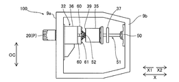
- the tool holder 21 is pulled out when excavating tool 20 is replaced by using a tool holding jack 51 as shown in FIG.
- the rear surface member 9b of the spoke portion 9 is provided with a jack mounting portion 50 at a position facing the opening 31a in the X direction.
- the tool holding jack 51 has a rear end portion attached to the jack attachment portion 50 and is arranged frontward, and the tip end portion is inserted into the inner peripheral surface of the tool holder 21.
- the rear end surface of the tool holder 21 and the rear end surface of the extension holder 22 are both configured to be screwed to the connecting member 52 of the tool holding jack 51.
- the tool holding jack 51 can move the screw portion 54 forward and backward with respect to the shaft portion 53.
- the screw portion 54 has a screw (male screw) formed on the outer peripheral surface.
- the connection member 52 is a nut member that meshes with the screw portion 54.
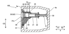
- the replacement of the first seal member 39 is performed by pulling out the inner guide member 35 from the outer guide member 36 while the excavation tool 20 is kept at the projecting position P.
- the exchanging method of the first seal member 39 will be described from the state of excavation in which the excavation tool 20 is arranged at the protruding position P.
- an operator installs the tool holding jack 51 on the jack mounting portion 50.
- the operator inserts the screw portion 54 into the extension holder 22 to connect the connecting member 52 to the rear end portion of the extension holder 22.
- the unit of the excavating tool 20, the tool holder 21, and the extension holder 22 is connected to the tool holding jack 51.
- an operator removes the bolts 37a and 37b of the fixing flange 37, and then removes the fixing flange 37. Further, the worker removes the fixing member 38 (see FIGS. 2 and 4) to release the fixing state of the inner guide member 35 to the outer guide member 36. Then, the worker pulls out the inner guide member 35.
- the inner guide member 35 is pulled out rearward (toward the non-face) from between the outer guide member 36 and the tool holder 21 and the extension holder 22.
- the inner guide member 35 is pulled out until it is separated from the outer guide member 36. As a result, the first seal member 39 at the tip of the inner guide member 35 is exposed.
- a second seal member 40 (see FIG. 2) provided in the fitting portion 21a of the tool holder 21 seals the outside (face side) and the inside (counter face side) of the front plate 31. Therefore, invasion of earth and sand or muddy water from the front surface 3a side is suppressed by the second seal member 40.
- the tool holding jack 51 is arranged inside the inner guide member 35, so the inner guide member 35 cannot be removed as it is.
- the operator can cut a part of the annular first seal member 39 and remove it from the inner guide member 35.
- the cut parts can be joined.
- the joining can be performed by adhesion, vulcanization or welding.
- the first seal member 39 can be replaced without completely removing the inner guide member 35.
- the temporary fixing piece 60 is a pair (two members) of fixing jigs divided into an upper side and a lower side in FIG. Since the temporary fixing piece 60 is not an annular shape but is divided into two members, the tool holding jack 51 can be attached even when it is connected to the extension holder 22.
- the temporary fixing piece 60 is fixed to the end surface of the outer guide member 36 and the extension holder 22 by a plurality of bolts 61. Thereby, the unit of the excavation tool 20, the tool holder 21, and the extension holder 22 is fixed to the outer guide member 36 via the temporary fixing piece 60.
- the worker removes the connection member 52 (see FIG. 10) from the extension holder 22 and removes the tool holding jack 51 (see FIG. 10) from the extension holder 22.
- the tool holding jack 51 passing through the inside of the inner guide member 35 is removed.
- the operator can completely remove the inner guide member 35 from the excavation tool changer 100.
- the operator removes the first seal member 39 from the removed inner guide member 35 and installs a new first seal member 39.
- the worker After replacing the first seal member 39, the worker inserts the inner guide member 35 between the outer guide member 36 and the tool holder 21 (and the extension holder 22) by the procedure reverse to the above, and attaches it. Detailed description is omitted.
- the first seal member 39 is replaced as described above.
- Step S1 The excavation tool 20 is retracted to a position on the side opposite to the face of the gate plate 33.
- Step S2 The gate plate 33 is moved from the open position Q1 to the closed position Q2.
- Step S3 The excavation tool 20 is pulled out from the guide portion 32.
- Step S4 The extracted drilling tool 20 is replaced with a new drilling tool 20.
- Step S5 The steps S1 to S3 are executed in the reverse order, and a new excavation tool 20 is placed at the protruding position P.
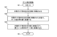
- Step S2 in the exchanging method of the excavating tool 20 according to the first embodiment, in the step S2 of moving the gate plate 33 from the open position Q1 to the closed position Q2, as shown in FIG. 13, the following steps S21 to S23 are performed.
- Step S21 The inner guide member 35 is moved to the opposite face side.
- Step S22 The gate plate 33 is arranged at the closed position Q2 that closes the opening 31a in a state where the inner guide member 35 is moved to the side opposite to the face.
- Step S23 In a state where the gate plate 33 is arranged at the closed position Q2, the inner guide member 35 is moved to the cutting face side to bring the first seal member 39 into close contact with the gate plate 33.
- FIG. 7 a method of exchanging the excavation tool 20 will be described from the state of excavation in which the excavation tool 20 is arranged at the protruding position P.
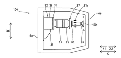
- FIG. 8 an operator installs the tool holding jack 51 on the jack mounting portion 50. The operator connects the connecting member 52 to the rear end of the extension holder 22. As a result, the unit of the excavating tool 20, the tool holder 21, and the extension holder 22 is connected to the tool holding jack 51.
- an operator removes the bolt 37a of the fixing flange 37 and removes the fixing flange 37 from the inner guide member 35.
- the operator contracts the tool holding jack 51 by a predetermined stroke. Specifically, the tool holding jack 51 is contracted until the tip of the excavation tool 20 is arranged behind the gate plate 33 (on the side opposite to the cutting face).
- the unit of the excavation tool 20, the tool holder 21, and the extension holder 22 is pulled out until the groove portion 21b formed in the outer peripheral surface of the tool holder 21 reaches the position of the rear end surface of the inner guide member 35.
- step S1 is the work of step S1.
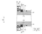
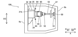
- step S2 the worker attaches the temporary fixing piece 64 to the inner guide member 35 with the bolt 65.
- the temporary fixing piece 64 is a pair (two members) of fixing jigs divided into an upper side and a lower side in FIG. Since the temporary fixing piece 64 is not an annular shape but is divided into two members, the tool holding jack 51 can be attached even when the tool holding jack 51 is still connected to the extension holder 22.
- the temporary fixing piece 64 is fixed to the end surface of the inner guide member 35 with a bolt 65.
- the temporary fixing piece 64 is arranged in the groove portion 21b of the tool holder 21. As a result, the units of the excavation tool 20, the tool holder 21, and the extension holder 22 engage with the inner guide member 35 via the temporary fixing piece 64.
- the length between the inner surfaces of the groove portions 21b of the tool holder 21 is longer than the length of the temporary fixing piece 64 arranged in the groove portions 21b in the front-rear direction (X direction). That is, in the groove 21b, there is a clearance CL in the front-rear direction between the temporary fixing piece 64 and the inner surface of the groove 21b. Therefore, the inner guide member 35 to which the temporary fixing piece 64 is attached can move backward by the clearance CL.
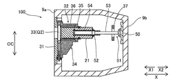
- the above step S21 is performed. That is, as shown in FIG. 17, the worker loosens the fixing member 38 for fixing the inner guide member 35 to the outer guide member 36.
- the inner guide member 35 moves rearward (on the side opposite to the face) as shown by the arrow, by the amount by which the fixing member 38, which is a bolt, is loosened.
- the first seal member 39 also moves rearward as the inner guide member 35 moves rearward.
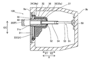
- the inner guide member 35 is moved to the face opposite to the face by a predetermined distance CL at which the first seal member 39 is not in contact with the gate plate 33 moving to the closed position Q2. That is, the first seal member 39 moves rearward by a predetermined distance CL from the position where the end face on the side opposite to the face of the gate plate 33 is arranged.
- the size of the clearance CL may be any size as long as the first seal member 39 can be brought into non-contact with the gate plate 33 moving to the closed position Q2.
- the clearance CL may be about several mm, for example, 5 mm.
- the tool holder 21 Since the tool holder 21 is supported by the tool holding jack 51, it does not move.
- the inner guide member 35 and the temporary fixing piece 64 move rearward in the groove 21b without changing the position of the tool holder 21. Further, the inner guide member 35 moves by the predetermined distance CL while being connected to the outer guide member 36 by the fixing member 38. The operator only loosens the fixing member 38. Since it is not necessary to remove the fixing member 38, it is possible to return the inner guide member 35 to the cutting face side (front side) only by refastening the loosened fixing member 38 in step S23 described later.
- step S22 is carried out. That is, as shown in FIG. 18, the operator moves the gate plate 33 at the open position Q1 toward the closed position Q2 in the OC direction. The worker rotates the screw shaft 41 to send the gate plate 33 toward the closed position Q2. It can be confirmed that the gate plate 33 has reached the closed position Q2 by the rod 43a (see FIG. 3) of the gate detection unit 43 on the closed position Q2 side protruding. At this time, the inner guide member 35 remains moved to the side opposite to the face by the predetermined distance CL.
- the gate plate 33 moves in step S22, the gate plate 33 moves to the closed position Q2 without being in contact with the first seal member 39.
- the second seal member 40 of the fitting portion 21a comes into contact with the inner peripheral surface of the inner guide member 35.
- the second seal member 40 seals between the inner guide member 35 and the tool holder 21.
- the space between the inner guide member 35 and the outer guide member 36 is sealed by a third seal member 35b (see FIG. 17) provided on the outer peripheral surface of the inner guide member 35.
- step S23 the above step S23 is carried out. That is, as shown in FIG. 19, the worker tightens the fixing member 38 for fixing the inner guide member 35 to the outer guide member 36. As indicated by the arrow, the inner guide member 35 moves forward (toward the cutting face) by the amount of tightening the fixing member 38, which is a bolt. The inner guide member 35 moves forward by the predetermined distance CL moved backward in step S21 (see FIG. 17). As a result, the first seal member 39 at the tip of the inner guide member 35 comes into contact (adhesion) with the non-face face of the gate plate 33 arranged at the closed position Q2. The first seal member 39 seals between the inner guide member 35 and the gate plate 33. Further, as a result, the inner guide member 35 returns to the fixed state in which it is fixed to the outer guide member 36 by the fixing member 38.
- step S3 the worker moves to work in step S3 (see FIG. 12).
- the operator removes the connecting member 52 from the extension holder 22.
- the worker removes the bolt 37 b and removes the fixing flange 37 from the extension holder 22.
- the operator removes the extension bolt 23 to remove the extension holder 22 from the tool holder 21. Since the extension holder 22 is composed of two members, the extension holder 22 can be divided and removed even when the tool holding jack 51 is still inserted.
- the operator extends the tool holding jack 51 and inserts the screw portion 54 into the tool holder 21. Then, the worker attaches the connecting member 52 to the rear end surface of the tool holder 21. Next, the worker removes the temporary fixing piece 64 as shown in FIG. As a result, the engagement between the inner guide member 35 and the tool holder 21 is released. Next, as shown in FIG. 25, the worker retracts the tool holding jack 51 to pull out the excavating tool 20 and the tool holder 21 from the inner guide member 35. As a result, the excavation tool 20 is taken out of the excavation tool changing device 100.
- step S4 the worker replaces the extracted excavation tool 20 with a new excavation tool 20, and attaches it to the excavation tool exchanging device 100 (step S4, see FIG. 12).
- the operator places the new excavation tool 20 at the protruding position P (step S5, see FIG. 12). Since this work is performed in the reverse order of the above, detailed description will be omitted.
- the gate plate 33 is moved from the closed position Q2 to the open position Q1, as shown in FIG. 17, the fixing member 38 is loosened to move the first seal member 39 by the predetermined distance CL, and the gate plate 33 is moved. The plate 33 is not contacted. Therefore, the gate plate 33 moves from the closed position Q2 to the open position Q1 while not in contact with the first seal member 39.
- the guide portion 32 moves the inner guide member 35 that guides the forward and backward movement of the excavating tool 20, and the inner guide member 35 to the face side and the face opposite to the face.
- a first seal member 39 that includes an outer guide member 36 that supports the inner guide member 35 is provided at the end of the inner guide member 35 on the face side, which is in close contact with the gate plate 33 from the side opposite to the face. Accordingly, by moving the inner guide member 35 along the outer guide member 36 to the side opposite to the cutting face, the first seal member 39 provided at the end face on the cutting face side of the inner guide member 35 is moved from the outer guide member 36.
- the first seal member 39 can be replaced by exposing it on the face side.
- the first seal member 39 can be replaced without disassembling the entire excavation tool replacement device 100.
- the first seal member 39 for suppressing the inflow of earth and sand or muddy water can be easily exchanged when exchanging the excavation tool 20.
- the inner guide member 35 having the first seal member 39 can be moved to the non-face side, so the inner guide member 35 is moved to the non-face side by the procedure shown in FIG. In this state, the gate plate 33 can be moved to close the opening 31a.
- the gate plate 33 can be moved in a non-contact state in which the first seal member 39 is separated from the gate plate 33 by moving the inner guide member 35 to the opposite face side.
- the inner guide member 35 is moved to the face of the face to bring the first seal member 39 into close contact with the gate plate 33, whereby the sealing property can be secured.
- the first seal member 39 can be easily replaced, but also wear of the first seal member 39 can be suppressed and the number of seal replacements can be reduced.
- the second seal that seals the opening 31a in a state where the excavation tool 20 is disposed at the projecting position P on the face of the cutter head 3 through the opening 31a.
- the member 40 is further provided, and the inner guide member 35 is configured to be movable from the outer guide member 36 to the side opposite to the cutting face and to be able to be pulled out while the excavation tool 20 is kept at the protruding position P.
- the inner guide member 35 can be pulled out and the first seal member 39 can be replaced while the excavation tool 20 is arranged at the protruding position P while the second seal member 40 seals the opening 31a.
- the first seal can be easily maintained while the excavating tool 20 is kept at the projecting position P without performing the work for ensuring the seal of the opening 31a.
- the member 39 can be replaced.
- the fixing member 38 that fixes the inner guide member 35 to the outer guide member 36 is further provided, and the inner guide member 35 is fixed to the outer guide member 36 by the fixing member 38.
- the fixing member 38 When the state is relaxed, it is configured to be movable by the predetermined distance CL while being connected to the outer guide member 36 via the fixing member 38.
- the first seal member 39 can be separated from the gate plate 33 by moving the inner guide member 35 to the opposite face side.
- the wear of the first seal member 39 due to the sliding movement of the gate plate 33 can be suppressed.
- the inner guide member 35 is moved to the face of the face to bring the first seal member 39 into close contact with the gate plate 33, and the inner guide member 35 is fixed. Therefore, the sealability of the first seal member 39 can be secured.
- the tunnel machine 1 includes the excavating tool exchanging device 100 configured as described above, and thus the first sealing member for suppressing the inflow of earth and sand or muddy water during exchanging the excavating tool 20. 39 can be easily replaced. Further, since the gate plate 33 can be moved to close the opening 31a in a state where the inner guide member 35 is moved to the face opposite to the face, the first seal member caused by sliding when the gate plate 33 is moved. The wear of 39 can be suppressed. Therefore, not only the first seal member 39 can be easily replaced, but also the wear of the first seal member 39 can be suppressed and the number of seal replacements can be reduced.
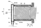
- a gate plate 133 is provided instead of the gate plate 33 (see FIG. 2).
- the gate plate 133 has an inclined surface 134 that is inclined toward the face of the face in the direction of closing the opening 31a (that is, toward the closed position Q2).
- the inclined surface 134 is configured to be in close contact with the first seal member 39 at the closed position Q2 where the gate plate 133 closes the opening 31a.
- the gate plate 133 has a first face on the face side facing the front plate 31 and a second face on the opposite face side.
- the second surface on the side opposite to the face is an inclined surface 134.
- the inclined surface 134 is arranged at a position where the end portion 134b on the closed position Q2 side is displaced from the end portion 134a on the open position Q1 side toward the face of the face (front side).
- the surface between the end portion 134b and the end portion 134a is inclined to the front plate 31 side (cut face side) by the angle ⁇ .
- the first surface of the gate plate 133 extends substantially parallel to the front plate 31 along the front plate 31 (see FIG. 26). For this reason, the thickness t of the gate plate 133 in the front-rear direction becomes smaller from the end portion 134a on the open position Q1 side toward the end portion 134b on the closed position Q2 side.
- the gate plate 133 linearly moves in the OC direction along the front plate 31.
- an inner guide member 135 is provided instead of the inner guide member 35 (see FIG. 2).
- the end face of the inner guide member 135 on the face side is an inclined surface 136 corresponding to the inclined surface 134 of the gate plate 133. That is, the inner guide member 135 has an inclined face on the face side, which is obtained by cutting the cylinder along a plane inclined by the angle ⁇ .
- the first seal member 39 is provided on the end face of the inner guide member 135 on the face side.
- the end face 39b on the closed position Q2 side of the first seal member 39 is also arranged at a position displaced to the face end (front side) from the end 39a on the open position Q1 side. And is inclined by an angle ⁇ .
- the end portion 134b of the inclined surface 134 becomes a portion on the end portion 39a side of the first seal member 39. Pass without contact.
- the end portion 134b of the inclined surface 134 comes into contact with the end portion 39b side portion of the first seal member 39. That is, the inclined surface 134 of the gate plate 133 does not come into contact with the first seal member 39 until it reaches the vicinity of the closed position Q2, and when it reaches the vicinity of the closed position Q2, the inclined surface 134 becomes Get in touch.
- the inclined surface 134 and the first seal member 39 of the inclined surface 136 come into close contact with each other, and the gap between the gate plate 133 and the inner guide member 135 is sealed. To be done.
- the first seal member 39 for suppressing the inflow of earth and sand or muddy water can be easily replaced when the excavation tool 20 is replaced.
- the gate plate 133 has the inclined surface 134 that is inclined toward the face face toward the direction of closing the opening 31a, and the gate plate 133 is at the closed position where the opening 31a is closed.
- the inclined surface 134 is configured to be in close contact with the first seal member 39. That is, the inclined surface 134 is inclined so as to move away from the first seal member 39 as it goes toward the tip of the gate plate 133 on the closed position Q2 side. As a result, the seal is ensured by the contact between the inclined surface 134 and the sealing surface (the surface on which the first sealing member 39 is arranged) inclined according to the inclined surface 134.
- the gate plate 133 when the gate plate 133 is closed, the inclined surface 134 and the first seal member 39 are not in contact with each other for most of the moving distance of the gate plate 133, and the gate plate 133 and the first seal member 39 are in contact with each other immediately before the gate plate 133 is placed in the closed position Q2.
- the first seal member 39 starts to contact.
- the gate plate 133 is opened, as soon as the gate plate 133 moves away from the closed position Q2, the inclined surface 134 and the first sealing member 39 are not in contact with each other.
- it is not necessary to move the inner guide member 135 to the side opposite to the face it is possible to suppress wear of the first seal member 39 without requiring special work by an operator.
- a gate guide portion 234 (see a chain double-dashed line) is provided instead of the gate guide portion 34c (see FIG. 3).
- a gate plate 233 is provided in place of the gate plate 33 (see FIG. 2).
- the gate guide portion 234 is configured to guide the gate plate 233 in the direction in which the gate plate 233 is pressed against the first seal member 39 (that is, the side opposite to the cutting face) before the closed position Q2 where the gate plate 233 closes the opening 31a. There is.
- the formation position of the gate guide portion 234 is the same as in the first embodiment (gate guide portion 34c, see FIG. 2). That is, as shown in FIG. 30, the gate guide portion 234 is provided on each of the pair of inner side surfaces extending along the OC direction in the gate accommodating portion 34a.
- the gate guide portion 234 is composed of a groove portion. Each of the pair of side end faces along the OC direction of the gate plate 233 is provided with a convex portion 235 arranged in the gate guide portion 234 and moving along the gate guide portion 234.
- the gate guide portion 234 of the third embodiment extends in the OC direction as a whole, but before the closed position Q2, on the side of the first seal member 39 (opposite face). Side, the inner guide member 35 side).
- the gate guide portion 234 composed of a groove portion has a guide surface which is an inner side surface of the groove portion.
- the gate guide portion 234 extends from the front of the closed position Q2 (the position shifted from the closed position Q2 toward the open position Q1 side) to the closed position Q2 with the first guide surface 234a extending linearly in the OC direction.
- the second guide surface 234b inclined toward the first seal member 39 side is included.
- the gate guide portion 234 guides the gate plate 233 in the open position Q1 such that the surface opposite to the face of the gate plate 233 is separated from the first seal member 39 toward the face of the face (forward).
- the gate plate 233 moves toward the closed position Q2 in the OC direction
- the second guide surface 234b and the face 235a on the face side of the convex portion 235 contact each other before the closed position Q2.
- the gate plate 233 moves diagonally toward the non-facet side along the inclination direction of the second guide surface 234b so that the gate plate 233 approaches the first seal member 39 side. To do.
- the gate plate 233 and the first sealing member 39 are not in contact with each other while the gate plate 233 moves along the first guide surface 234a.
- the gate plate 233 begins to come into contact with the first seal member 39 as the gate plate 233 obliquely moves along the second guide surface 234b.
- the gate plate 233 When the gate plate 233 reaches the closed position Q2, the gate plate 233 is in a state in which the gate plate 233 is in close contact with the first seal member 39 because the face of the convex portion 235 is supported by the second guide surface 234b. Maintained.
- the screw shaft 41 that meshes with the nut portion 33b also moves to the first seal member 39 side (counter face side). That is, in the third embodiment, a gap CL2 is provided between the opening of the cover 42 that holds the screw shaft 41 and the screw shaft 41 so that the clearance CL2 is movable toward the cutting face and the opposite face.
- the screw shaft 41 slides in the opening of the cover 42 to the non-cut face side as the gate plate 233 moves to the non-cut face side. To do.
- the gate plate 233 moves from the closed position Q2 to the open position Q1
- the third guide surface 234c facing the second guide surface 234b and the non-face face 235b of the convex portion 235 contact each other in the gate guide portion 234.
- the convex portion 235 is guided along the third guide surface 234c.
- the third guide surface 234c is an inclined surface that is substantially parallel to the second guide surface 234b. Therefore, the gate plate 233 immediately separates from the first seal member 39 along the second guide surface 234b.
- the gate plate 233 and the first seal member 39 do not move without moving the inner guide member 35 to the face opposite to the face as in the first embodiment. Sliding is reduced.
- the first seal member 39 for suppressing the inflow of earth and sand or muddy water can be easily replaced when the excavation tool 20 is replaced.
- the gate guide portion 234 guides the gate plate 233 in the direction in which the gate plate 233 is pressed against the first seal member 39 before the closed position Q2 in which the gate plate 233 closes the opening 31a. Is configured to. As a result, the gate plate 233 can be moved to the vicinity of the closed position Q2 while the first seal member 39 is separated from the gate plate 233. Then, when the gate plate 233 has moved to the position before the closed position Q2, the gate guide portion 234 guides the gate plate 233 to the first seal member 39 side, so that the gate plate 233 and the first seal member 39 are in close contact with each other. Begin to.
- the gate plate 233 and the first sealing member 39 can be brought into non-contact with each other as soon as the gate plate 233 leaves the closed position Q2. As a result, it is possible to suppress wear of the first seal member 39 due to sliding when the gate plate 233 is opened and closed.
- the tunnel excavator is a shield excavator with an intermediate support method
- the tunnel excavator of the present invention may be applied to shield excavators of various supporting methods such as a center shaft supporting method, an outer peripheral supporting method, a central supporting method and an eccentric multi-axis supporting method other than the above supporting methods.
- the present invention may be applied not to the shield machine, but to a machine using a propulsion method or a tunnel boring machine.
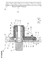
- the second seal member 40 is provided, but the present invention is not limited to this. In the present invention, the second seal member 40 may not be provided. Further, in the above-described first to third embodiments, the example in which the second seal member 40 is provided on the outer peripheral surface of the fitting portion 21a of the tool holder 21 has been shown, but the second seal member 40 does not fit in the fitting portion 21a. It may be provided at a position other than the outer peripheral surface. For example, the outer diameter of the tool holder 21 is made larger than the inner diameter of the opening 31a so that the tip surface of the tool holder 21 abuts on the peripheral edge of the opening 31a. The second seal member 40 may be annularly provided on the tip surface of the tool holder 21 at a position where it contacts the peripheral edge of the opening 31a.
- the inner guide member 35 can be pulled out to the side opposite to the face when the first seal member 39 is replaced and the excavating tool 20 is kept at the projecting position P.
- the present invention is not limited to this.
- the inner guide member 35 may be pulled out in a state where the excavation tool 20 is arranged at a position other than the protruding position P.
- the worker places the gate plate 33 at the closed position Q2 and pulls out the excavating tool 20 (tool holder 21), as in the case of exchanging the excavating tool 20. Then, the worker presses the gate plate 33 against the front plate 31 using a dedicated jack (not shown) to bring the gate plate 33 into close contact with the front plate 31. In this state, the inner guide member 35 may be pulled out.
- the inner guide member 35 can be moved by a predetermined distance CL while being connected to the outer guide member 36 via the fixing member 38.
- the fixing member 38 may be completely removed.
- the inner guide member 35 may be configured to be movable to the cutting face side and the non-cutting face side only after the fixing member 38 is removed (the fixed state is released).
- the fixing member 38 that fixes the inner guide member 35 to the outer guide member 36 may be other than the bolt.
- the fixing member 38 may be, for example, a pin or a key. In that case, the fixing member 38 fixes the inner guide member 35 to the outer guide member 36 by, for example, penetrating the outer guide member 36 and being inserted into the engagement hole of the inner guide member 35.
- the gate plate and the first seal member 39 are not in contact with each other at least before the closed position Q2 when the gate plate is moved. That is, in the above-described first embodiment, the inner guide member 35 moves to the side opposite to the face, so that the gate plate 33 and the first seal member 39 are not in contact with each other. In the second embodiment, since the gate plate 133 has the inclined surface 134, the gate plate 133 and the first sealing member 39 are not in contact with each other. In the third embodiment, the gate guide portion 234 guides the gate plate 233 so that the gate plate 233 and the first seal member 39 are not in contact with each other. The present invention is not limited to these examples.
- the gate plate and the first sealing member 39 may contact each other when the gate plate moves. Even when the gate plate and the first sealing member 39 are in contact with each other, according to the respective configurations of the first to third embodiments, the gate plate to the first sealing member 39 are arranged in the closed position Q2.
- the pressing force from the gate plate to the first sealing member 39 during the movement of the gate plate is smaller than the pressing force to the. Therefore, since the frictional resistance is reduced, it is possible to reduce the wear of the first seal member 39 due to the sliding with the gate plate.
- the inner guide member 35 is moved to the side opposite to the face when the gate plate 33 is moved so that the gate plate 33 and the first seal member 39 are not in contact with each other.
- the invention is not limited to this.
- the gate plate 33 may be moved while the gate plate 33 and the first seal member 39 are in close contact with each other without moving the inner guide member 35. In that case, the first seal member 39 is easily worn by sliding, but as described above, the inner guide member 35 can be pulled out to easily replace the first seal member 39.
- the gate plate may move along any movement route as long as it can move to the open position Q1 and the closed position Q2 along the front plate 31.
- the gate plate may move to the open position Q1 and the closed position Q2 along the front plate 31 by rotating around the rotation axis extending in the front-rear direction.
- the excavating tool changing device 100 is provided in the spoke portion 9 of the cutter head 3 is shown, but the present invention is not limited to this.
- the excavation tool exchanging device 100 may be provided on a member other than the spoke portion as long as it is a member that constitutes the front surface 3a of the cutter head 3.
- the extension holder 22 may not be provided. That is, in the first embodiment, after the tool holder 21 and the extension holder 22 are pulled out to predetermined positions by the tool holding jack 51 in FIG. 14, the extension holder 22 is removed in FIG. 22 and the tool holder 21 is held in the tool holder 21 in FIG. A two-stage pulling operation is performed in which the jack 51 is attached and the tool holder 21 is pulled out by the tool holding jack 51 in FIG.
- the tool holder 21 is pulled out to a predetermined position by the tool holding jack 51 in FIG. 14 (first stage extraction), the gate plate 33 is closed (see FIG. 18 ), and then FIGS.
- the work can be performed by the procedure of pulling out the excavation tool 20 (second stage pulling out) in FIGS. 23 to 25.
- FIG. 32 shows an example of the excavating tool exchanging device 200 in which two opening portions 31a are provided for one front plate 331 and two excavating tools 20 are individually exchangeably held.
- the excavation tool exchanging device 200 has a guide portion 32 (not shown in FIG. 32) including a gate plate 33 and an inner guide member 35 and an outer guide member 36, one at each of the positions where the two openings 31a are formed. Is equipped with. That is, two structures shown in FIG. 2 are provided in parallel with respect to one front plate 331.
Landscapes
- Engineering & Computer Science (AREA)
- Mining & Mineral Resources (AREA)
- Environmental & Geological Engineering (AREA)
- Life Sciences & Earth Sciences (AREA)
- General Life Sciences & Earth Sciences (AREA)
- Geochemistry & Mineralogy (AREA)
- Geology (AREA)
- Excavating Of Shafts Or Tunnels (AREA)
Abstract
この掘削ツール交換装置(100)のガイド部(32)は、掘削ツール(20)の進退移動をガイドする内側ガイド部材(35)と、内側ガイド部材を切羽側および反切羽側に移動可能に支持する外側ガイド部材(36)と、を含む。内側ガイド部材の切羽側端部に、ゲート板(33)に反切羽側から密着する第1シール部材(39)が設けられている。
Description
本発明は、掘削ツール交換装置およびトンネル掘進機に関し、特に、カッタヘッドに着脱可能に設けられる掘削ツールを交換する技術に関する。
従来、トンネル掘進機の掘削ツールを交換する掘削ツール交換装置が知られている。このような掘削ツール交換装置は、たとえば、特許第3589653号公報に開示されている。
上記特許第3589653号公報には、カッタビットと、カッタビットを反切羽側へスライド可能に支持するガイド部と、カッタビットをカッタ面板から突出させる時に貫通させる貫入穴部、およびカッタビットを反切羽側へスライドさせた状態でカッタビット前面の開口部を塞ぐゲート蓋部を形成したスライドゲートと、スライドゲートを案内する案内部材とを設け、スライドゲートのスライド時に開口部の周囲で案内部材とスライドゲートとの間をシールするシール部材を設けたカッタビット交換装置が開示されている。カッタビットは、ガイドケースとガイド蓋との中に挿入された状態で保持されている。ガイドケースのスライドゲート案内部とガイド蓋の案内部蓋とによって案内部材が形成されている。シール部材は、ガイドケースとガイド蓋とに形成された溝部に設けられている。
上記特許第3589653号公報では、カッタビットの交換の際にスライドゲートが開口部を開閉すると、案内部材とスライドゲートとの間のシール部材がスライドゲートと摺動する。シール部材は、スライドゲートとの摺動や、摺動時に侵入する土砂によって損傷することがある。シール部材が損傷すると、シール性が低下するだけでなく、スライドゲートとの摺動時にシール部材が外れて、移動するスライドゲートと案内部材との隙間にシール部材が噛み込まれて動作不良になる可能性がある。そのため、シール部材の損傷が進行する前に、シール部材を交換できるようにすることが好ましい。
しかしながら、上記特許第3589653号公報では、シール部材の交換について考慮されていない。上記特許第3589653号公報には明記されていないが、シール部材を交換するには、土砂や泥水が流入しないように切羽側の地盤を改質した上で、ガイドケースとガイド蓋とを分解してスライドゲートを取り外す(つまり、カッタビット交換装置全体を分解する)必要があると考えられる。したがって、上記特許第3589653号公報の装置においてシール部材の交換は容易ではない。
そのため、掘削ツール交換時に土砂や泥水の流入を抑制するためのシール部材を容易に交換できるようにすることが望まれている。
この発明は、上記のような課題を解決するためになされたものであり、この発明の1つの目的は、掘削ツール交換時に土砂や泥水の流入を抑制するためのシール部材を容易に交換することが可能な掘削ツール交換装置およびトンネル掘進機を提供することである。
上記目的を達成するために、この発明の第1の局面における掘削ツール交換装置は、前面に掘削ツールが配置され、回転するカッタヘッドを備えたトンネル掘進機の掘削ツール交換装置であって、着脱可能な掘削ツールと、カッタヘッドの切羽側に開口して掘削ツールが通過する開口部を有する前面板と、開口部を介して掘削ツールを進退移動可能に支持するガイド部と、前面板とガイド部との間で前面板に沿ってスライド移動可能に構成され、開口部を開閉するゲート板と、を備え、ガイド部は、掘削ツールの進退移動をガイドする内側ガイド部材と、内側ガイド部材を切羽側および反切羽側に移動可能に支持する外側ガイド部材と、を含み、内側ガイド部材の切羽側端部に、ゲート板に反切羽側から密着する第1シール部材が設けられている。
なお、本明細書において、「トンネル掘進機」とは、シールド工法に用いられるシールド掘進機、推進工法に用いられる掘進機および山岳トンネル工法に用いられるトンネルボーリングマシンを含む広い概念である。シールド掘進機は、胴体およびカッタヘッドにより地山からの土圧、泥水圧に対抗しつつセグメントの組み立てを行い、組み立てられたセグメントから推進反力を得て掘進する装置である。推進工法は、掘進に伴い、発進部においてトンネル壁(コンクリートや鋼製の管)を追加し、それを押し込むことによって、掘進機を前進させる工法である。トンネルボーリングマシンは、主として岩盤などの比較的硬い地山の掘進に用いられ、土圧、泥水圧に対抗する切羽保持機能を持たず、トンネルを掘進する装置である。「切羽側」とは、カッタヘッドにより掘削される地山がある側であり、掘進方向の前側と言い換えても良い。「反切羽側」とは、切羽側とは反対側(坑口側)であり、掘進方向の後側と言い換えても良い。掘削ツールとは、カッタヘッドの前面に設けられ土砂を掘削する工具であり、カッタビット、ローラビットなどを含む概念である。
この発明の第1の局面による掘削ツール交換装置では、上記のように構成することによって、内側ガイド部材を外側ガイド部材に沿って反切羽側に移動させることにより、内側ガイド部材の切羽側端部に設けられた第1シール部材を、外側ガイド部材から反切羽側に露出させて、第1シール部材の交換作業を行うことができる。つまり、内外の二重のガイド部材のうち内側ガイド部材を引き抜くことによって、掘削ツール交換装置全体を分解することなく、第1シール部材を交換することができる。これにより、掘削ツール交換時に土砂や泥水の流入を抑制するためのシール部材を容易に交換することができる。
また、上記特許第3589653号公報のような従来の掘削ツール交換装置において、スライドゲートの開閉時には、上記の通り、シール部材が密着した状態でスライドゲートが移動するので、ゲート板との摺動によって第1シール部材が損傷する。これに対して、本発明の上記構成によれば、第1シール部材を有する内側ガイド部材を反切羽側に移動させることができるので、内側ガイド部材を反切羽側に移動させた状態で、ゲート板を移動させて開口部を閉じることができる。この場合、内側ガイド部材の反切羽側への移動により、第1シール部材をゲート板から離間させた非接触の状態か、または第1シール部材がシール時よりも弱い押圧力でゲート板に接触する状態で、ゲート板を移動させることができる。この結果、ゲート板の移動時における摺動に起因する第1シール部材の損耗を抑制することができる。なお、ゲート板の移動後、内側ガイド部材を切羽側に移動させて第1シール部材をゲート板に密着させることにより、シール性を確保することができる。このように、本発明によれば、第1シール部材を容易に交換可能とするだけでなく、第1シール部材の損耗を抑制してシール交換回数を低減することができる。
上記第1の局面による掘削ツール交換装置において、好ましくは、掘削ツールが開口部を介してカッタヘッドの切羽側の突出位置に配置された状態で、開口部を封止する第2シール部材をさらに備え、内側ガイド部材は、掘削ツールが突出位置に配置されたままで、外側ガイド部材から反切羽側に移動して引き抜き可能に構成されている。このように構成すれば、掘削ツールが突出位置に配置された状態で、第2シール部材によって開口部をシールしたまま、内側ガイド部材を引き抜いて第1シール部材を交換できる。これにより、内側ガイド部材を反切羽側に移動させる際に、開口部のシールを確保するための作業を行うことなく、掘削ツールを突出位置に配置したままで簡単に第1シール部材を交換できる。
上記第1の局面による掘削ツール交換装置において、好ましくは、内側ガイド部材を外側ガイド部材に対して固定する固定部材をさらに備え、内側ガイド部材は、固定部材による外側ガイド部材に対する固定状態が緩和されることにより、固定部材を介して外側ガイド部材に連結されたまま、所定距離だけ移動可能となるように構成されている。なお、「固定部材」は、ボルト(ねじ)、ピンまたはキーなどを含む概念である。上記のように構成すれば、ゲート板の移動時に、内側ガイド部材の固定状態を緩和して、内側ガイド部材を所定距離だけ反切羽側に移動させることができる。内側ガイド部材の反切羽側への移動により、第1シール部材をゲート板から離間させるか、または第1シール部材がシール時よりも弱い押圧力でゲート板に接触する状態で、ゲート板を移動させることができる。この結果、ゲート板の移動時における摺動に起因する第1シール部材の損耗を抑制することができる。なお、ゲート板が閉位置に移動した後、内側ガイド部材を切羽側に移動させて第1シール部材をゲート板に密着させて、内側ガイド部材を固定状態にすることで、第1シール部材によるシール性を確保することができる。
上記第1の局面による掘削ツール交換装置において、好ましくは、ゲート板は、開口部を閉じる方向に向かうに従って切羽側に傾斜した傾斜面を有し、ゲート板が開口部を閉じる閉位置において、傾斜面が第1シール部材と密着するように構成されている。すなわち、傾斜面が、開口部を閉じる方向に向かうほど、第1シール部材から離れるように傾斜している。このように構成すれば、傾斜面と、傾斜面に応じて傾斜したシール面(第1シール部材が配置される面)との接触によりシールが確保される構造となる。そのため、ゲート板を閉じる際、ゲート板の移動距離の大半では傾斜面と第1シール部材とが非接触となり、ゲート板が閉位置に配置される直前にゲート板と第1シール部材とが接触し始める。逆に、ゲート板を開く際、ゲート板が閉位置から離れるとすぐに、傾斜面と第1シール部材とが非接触となる。この結果、ゲート板の移動時における摺動に起因する第1シール部材の損耗を抑制することができる。また、内側ガイド部材を反切羽側に移動させる必要がないので、作業者による特段の作業を必要とすることなく第1シール部材の損耗を抑制することができる。
上記第1の局面による掘削ツール交換装置において、好ましくは、ゲート板のスライド移動を案内するゲートガイド部をさらに備え、ゲートガイド部は、ゲート板が開口部を閉じる閉位置の手前で、ゲート板を第1シール部材に押し付ける方向へ案内するように構成されている。このように構成すれば、第1シール部材をゲート板から離間させるか、または第1シール部材がシール時よりも弱い押圧力でゲート板に接触する状態で、ゲート板を閉位置付近まで移動させることができる。そして、ゲート板が閉位置の手前まで移動した段階で、ゲートガイド部がゲート板を第1シール部材側に案内することによって、ゲート板と第1シール部材とが密着し始める。逆に、ゲート板を開く際、ゲート板が閉位置から離れるとすぐに、ゲート板と第1シール部材とが非接触となるか、または第1シール部材に対するゲート板の押圧力を弱めることができる。この結果、ゲート板の開閉時における摺動に起因する第1シール部材の損耗を抑制することができる。
この発明の第2の局面におけるトンネル掘進機は、前面に掘削ツールが配置されたカッタヘッドと、カッタヘッドを回転させるカッタ駆動部と、掘削ツールを交換可能に支持する掘削ツール交換装置と、を備え、掘削ツール交換装置は、着脱可能な掘削ツールと、カッタヘッドの切羽側に開口して掘削ツールが通過する開口部を有する前面板と、開口部を介して掘削ツールを進退移動可能に支持するガイド部と、前面板とガイド部との間で前面板に沿ってスライド移動可能に構成され、開口部を開閉するゲート板と、を含み、ガイド部は、掘削ツールの進退移動をガイドする内側ガイド部材と、内側ガイド部材を切羽側および反切羽側に移動可能に支持する外側ガイド部材と、を含み、内側ガイド部材の切羽側端部に、ゲート板に反切羽側から密着する第1シール部材が設けられている。
この発明の第2の局面によるトンネル掘進機では、上記第1の局面と同様に、内側ガイド部材を外側ガイド部材に沿って反切羽側に移動させることにより、内側ガイド部材の切羽側端部に設けられた第1シール部材を、外側ガイド部材から反切羽側に露出させて、第1シール部材の交換作業を行うことができる。これにより、掘削ツール交換時に土砂や泥水の流入を抑制するためのシール部材を容易に交換することができる。
さらに、上記構成によれば、内側ガイド部材を反切羽側に移動させた状態で、ゲート板を移動させて開口部を閉じることができるので、ゲート板の移動時における摺動に起因する第1シール部材の損耗を抑制することができる。このように、本発明によれば、第1シール部材を容易に交換可能とするだけでなく、第1シール部材の損耗を抑制してシール交換回数を低減することができる。
本発明によれば、上記のように、掘削ツール交換時に土砂や泥水の流入を抑制するためのシール部材を容易に交換することができる。
以下、本発明の実施形態を図面に基づいて説明する。
[第1実施形態]
図1~図6を参照して、本発明の第1実施形態によるトンネル掘進機1および掘削ツール交換装置100について説明する。以下では、トンネル掘進機1が、シールド掘進機である例を説明する。
図1~図6を参照して、本発明の第1実施形態によるトンネル掘進機1および掘削ツール交換装置100について説明する。以下では、トンネル掘進機1が、シールド掘進機である例を説明する。
(トンネル掘進機の全体構成)
図1に示すように、トンネル掘進機1は、筒状の胴体2と、カッタヘッド3と、カッタ駆動部4と、掘削ツール交換装置100と、を備えている。
図1に示すように、トンネル掘進機1は、筒状の胴体2と、カッタヘッド3と、カッタ駆動部4と、掘削ツール交換装置100と、を備えている。
図1では、カッタヘッド3の支持方式として中間支持方式を採用した中~大口径タイプのシールド掘進機を例示している。中間支持方式では、カッタヘッド3は、回転駆動される円環状の支持部材5に対して、カッタコラム6を介して取り付けられている。カッタコラム6は、支持部材5とカッタヘッド3とを接続する脚部である。支持部材5は、後述する前胴部2aの隔壁(バルクヘッド)7に設けられた旋回台軸受8により回転可能に支持されている。
トンネル掘進機1は、図1中の左方向(X1方向)に掘進する。図1中、カッタヘッド3に対して左側が掘進中のトンネルの切羽側であり、右側がトンネルの反切羽側(坑口側)である。各図において、掘進方向の前後方向をX方向とし、掘進方向の前方(切羽側)をX1方向とし、掘進方向の後方(反切羽側)をX2方向として図示している。以下では、単に前方、前面というとき、掘進方向の前方(X1方向、切羽側)を意味し、後方、後側というとき、掘進方向の後方(X2方向、反切羽側)を意味する。
トンネル掘進機1の胴体2は、前胴部2aと後胴部2bとを含む。胴体2は、掘進方向の前側の前胴部2aと、後側の後胴部2bとに分割されている。前胴部2aおよび後胴部2bは、たとえば円筒状に形成されている。前胴部2aは、掘進方向の前側が隔壁7によって塞がれており、隔壁7に設けられた旋回台軸受8を介して、カッタヘッド3を前胴部2aの前端面の位置に保持している。後胴部2bは、前胴部2aの掘進方向後端部に連結されている。
カッタヘッド3は、中心軸線A回りに回転するように構成されている。カッタヘッド3は、掘進方向から見て前胴部2aの端面形状に対応した形状に形成されている。すなわち、カッタヘッド3は、掘進方向から見て円形状に形成されている。
カッタヘッド3は、中心軸線Aから半径方向に延びるスポーク部9を含む。スポーク部9は、半径方向に直線状に設けられた中空筒状の梁部材である。スポーク部9の中心側端部は、中心軸線Aに沿って延びる中空のセンターシャフト10に連結している。スポーク部9の前面部材9aは、カッタヘッド3の前面3aの一部を構成する。スポーク部9の後面部材9bに、カッタコラム6が接続されている。
カッタヘッド3の前面3aには、掘削ツール20が配置されている。掘削ツール20は、カッタヘッド3の前面3aから前方(切羽側)に突出するように設けられている。掘削ツール20は、カッタヘッド3の回転に伴い地山を掘削するための工具である。掘削ツール20は、たとえばカッタビットまたはディスクカッタなどにより構成されている。掘削ツール20は、掘削ツール交換装置100に着脱可能に設けられている。
掘削ツール交換装置100は、カッタヘッド3の前面3aに掘削ツール20を保持するように、カッタヘッド3に設置されている。掘削ツール交換装置100は、掘削ツール20を交換可能に支持する。掘削ツール交換装置100は、中空のスポーク部9の内部に設置されている。掘削ツール交換装置100は、スポーク部9の内側から、スポーク部9の前面部材9aに対して固定されている。
掘削ツール交換装置100は、掘進時に、カッタヘッド3の前面3aよりも切羽側に突出した突出位置Pに掘削ツール20を保持することができる。掘削ツール交換装置100は、カッタヘッド3の前面3aよりも反切羽側のスポーク部9の内部まで掘削ツール20を後退させて、掘削ツール20を取り外すことが可能に構成されている。掘削ツール交換装置100により、スポーク部9の内部で掘削ツール20の交換作業が行える。掘削ツール交換装置100の詳細については後述する。
カッタコラム6は、中空筒状の梁部材(ビーム)である。カッタコラム6は、カッタヘッド3を支持し、かつ、カッタヘッド3と共に回転する。カッタコラム6は、一方端部がカッタヘッド3に取り付けられ、他方端部が円環状の支持部材5に取り付けられている。支持部材5が、旋回台軸受8によって回転可能に支持されている。これにより、カッタヘッド3が、旋回台軸受8によって中心軸線A回りに回転可能に支持されている。
カッタ駆動部4は、カッタヘッド3を回転させる。カッタ駆動部4は、たとえば油圧モータを含む。カッタヘッド3は、カッタ駆動部4によって旋回台軸受を介し、支持部材5に駆動トルクが付与されることにより、中心軸線A回りに回転駆動される。
掘削ツール20によって削られた掘削土は、カッタヘッド3の内部のチャンバ部11に進入する。チャンバ部11は、カッタヘッド3、前胴部2aの周壁および隔壁7によって囲まれた空間である。チャンバ部11内の掘削土は、排土装置12によって隔壁7を通って胴体2の内部に搬送された後、トンネルの外部まで排出される。
チャンバ部11内の掘削土は、排土装置12による排出量が制御されることにより、チャンバ部11内で泥土圧を発生させる。チャンバ部11内の泥土圧は、排土装置12によって、地山側からカッタヘッド3に作用する力の土圧成分(地山を構成する土による圧力)と概ね平衡状態となるように維持される。
トンネル掘進機1は、推進ジャッキ13を備える。推進ジャッキ13は、セグメント(図示せず)を押圧して胴体2(前胴部2aおよび後胴部2b)を推進させるシールドジャッキ13aと、後胴部2bから前胴部2aへ荷重を伝達する中折れジャッキ13bとを含む。トンネル掘進機1は、これらの推進ジャッキ13の推進力によって掘進方向前方に推進する。
トンネル掘進機1は、図示しないエレクタを備える。エレクタは、セグメント(図示せず)を環状(リング状)に組み立てる装置である。環状に組み立てられたセグメントは、トンネル掘進機1が構築するトンネルの壁面を構成する。トンネル掘進機1は、所定距離の掘進と、掘進を停止した状態でのセグメントの組み立てとを繰り返すことにより、トンネル壁面を構築しながら掘進する。
なお、センターシャフト10は、隔壁7を貫通して胴体2内に接続している。隔壁7よりも後側の胴体2内、センターシャフト10内およびスポーク部9内は、大気圧となっている。掘削ツール20の交換時に、作業者は、センターシャフト10の内部およびスポーク部9の内部を通って、掘削ツール交換装置100に対して作業を行うことができる。
(掘削ツール交換装置)
次に、図2~図6を参照して、掘削ツール交換装置100の構造について説明する。掘削ツール交換装置100は、主として、前面板31と、ガイド部32と、ゲート板33と、を備える。掘削ツール交換装置100は、掘削ツール20が着脱可能に取り付けられたツールホルダ21を備える。掘削ツール交換装置100は、前面板31とともにゲート板33を収容するハウジング34を備える。ガイド部32は、内側ガイド部材35と外側ガイド部材36とを備える。
次に、図2~図6を参照して、掘削ツール交換装置100の構造について説明する。掘削ツール交換装置100は、主として、前面板31と、ガイド部32と、ゲート板33と、を備える。掘削ツール交換装置100は、掘削ツール20が着脱可能に取り付けられたツールホルダ21を備える。掘削ツール交換装置100は、前面板31とともにゲート板33を収容するハウジング34を備える。ガイド部32は、内側ガイド部材35と外側ガイド部材36とを備える。
前面板31は、カッタヘッド3の前面3aに露出するように設けられた平板状の部材である。前面板31は、スポーク部9の前面部材9aに形成された開口に嵌合するように設けられている。前面板31は、カッタヘッド3の前面3aの一部を構成する。前面板31は、カッタヘッド3の切羽側に開口して掘削ツール20が通過する開口部31aを有する。開口部31aは、前面板31を厚み方向に貫通している。開口部31aは、掘削ツール20を突出位置Pに配置する際、および、掘削ツール20の交換時に掘削ツール20を引き込む際に、掘削ツール20が内部を通過する。開口部31aは、掘削ツール20が通過可能なように、掘削ツール20の外形形状に応じた開口形状を有する。
掘削ツール20は、円筒状のツールホルダ21の先端部に取り付けられている。ツールホルダ21は、切羽側(前方)に掘削ツール20を向けて、ガイド部32(内側ガイド部材35)内に配置されている。ガイド部32は、掘削ツール20が設けられたツールホルダ21を、前後方向に進退移動可能に支持している。これにより、ガイド部32は、開口部31aを介して掘削ツール20を進退移動可能に支持している。なお、ツールホルダ21の後端部には、円筒状の延長ホルダ22が延長ボルト23により連結されている。延長ホルダ22は、それぞれ半円筒状の2部材で構成され、半分ずつ分離可能である。
ハウジング34は、前面板31の後面(反切羽側面)を覆うように設けられている。ハウジング34は、前面板31の後面を覆うゲート収容部34aを有する。ゲート収容部34aは、前面板31に沿って延びている。ゲート収容部34aの前面板31との対向面には、前面板31との間にゲート板33を配置するための空間を形成する凹部34bが設けられている。ゲート収容部34aの凹部34bは、ゲート板33が開位置Q1(図3参照)と閉位置Q2(図3参照)とに移動可能な形状に形成されている。
図3に示すように、矩形状のゲート板33が、開口部31aを覆わない開位置Q1と、開口部31aを覆う閉位置Q2との間を、OC方向に直線移動する。凹部34bは、掘進方向から見て、ゲート板33の移動距離に応じた長方形状に形成されている。凹部34bのうち、OC方向に沿って延びる一対の内側面には、それぞれ、ゲートガイド部34cが設けられている。ゲートガイド部34cは、ゲート板33のスライド移動を案内するように構成されている、ゲートガイド部34cは、たとえば、OC方向に延びる溝部からなる。ゲート板33の側端面がゲートガイド部34c内に配置されており、ゲート板33の両端部がゲートガイド部34c内でOC方向にガイドされる。
図2に示すように、ハウジング34には、ガイド部32を構成する外側ガイド部材36が設けられている。外側ガイド部材36は、円筒形状のガイド筒であり、切羽側端面がゲート収容部34aの後面に接続している。ゲート収容部34aには、掘進方向から見て前面板31の開口部31aと同軸上に、開口部31aよりも一回り大きい貫通孔が形成されている。外側ガイド部材36は、貫通孔の周縁部を後方(反切羽側)に円筒状に延ばした形状を有する。このように、ハウジング34は、溶接などにより互いに一体化されたゲート収容部34aと外側ガイド部材36とを有している。また、ハウジング34には、ゲート収容部34aと外側ガイド部材36とを相互に固定する補強リブ34dが設けられている。
外側ガイド部材36は、内側ガイド部材35を切羽側および反切羽側(前後方向)に移動可能に支持している。すなわち、外側ガイド部材36の内周部に、内側ガイド部材35が配置されている。内側ガイド部材35は、円筒形状のガイド筒である。内側ガイド部材35は、外側ガイド部材36の内径に略一致する外径を有する筒状部を有する。内側ガイド部材35の筒状部が、外側ガイド部材36の内側に、前後方向へ摺動可能に挿入されている。内側ガイド部材35は、掘削ツール20が突出位置Pに配置されたままで、外側ガイド部材36から反切羽側に移動して引き抜き可能に構成されている。
内側ガイド部材35は、掘削ツール20の進退移動をガイドするように構成されている。内側ガイド部材35は、掘削ツール20が先端に取り付けられたツールホルダ21を、前後方向に摺動可能に支持している。内側ガイド部材35の内径は、開口部31aの内径に略一致する。また、掘削ツール20の外径が、内側ガイド部材35および開口部31aの内径に略一致する。このため、内側ガイド部材35内でツールホルダ21を切羽側に摺動させることにより、掘削ツール20を突出位置Pへ配置することができる。突出位置Pは、掘削ツール20が開口部31aを介してカッタヘッド3の切羽側(前面板31よりも切羽側)に突出する位置である。また、内側ガイド部材35内でツールホルダ21を反切羽側に摺動させることにより、掘削ツール20を後退させることができる。これにより、掘削ツール20をツールホルダ21とともに内側ガイド部材35から引き抜いて、掘削ツール20を交換することができる。
図2に示すように、内側ガイド部材35の後端部(反切羽側端部)には、径方向外側に向けて延びるフランジ部35aが設けられている。フランジ部35aは、外側ガイド部材36の後端部に重なっている。内側ガイド部材35は、フランジ部35aを前後方向に貫通して外側ガイド部材36に取り付けられる固定部材38によって、外側ガイド部材36に対して固定されている。固定部材38は、内側ガイド部材35を外側ガイド部材36に対して固定するボルト(ねじ)である。なお、図4に示すように、固定部材38は、フランジ部35aの周方向に沿って複数設けられている。固定部材38は、実際には図2に示す断面上には現れないが、説明のため、図2にも便宜的に図示している。
固定部材38は、フランジ部35aの貫通孔を通って外側ガイド部材36の後端部に形成されたねじ孔に締結されている。内側ガイド部材35は、固定部材38によって外側ガイド部材36に固定されている。固定部材38は、フランジ部35aを、反切羽側から貫通して、外側ガイド部材36に対して切羽側に締め付けている。内側ガイド部材35は、固定部材38による外側ガイド部材36に対する固定状態が緩和されることにより、固定部材38を介して外側ガイド部材36に連結されたまま、所定距離だけ移動可能となるように構成されている。すなわち、ボルトである固定部材38を弛めて固定状態を緩和すると、固定部材38が反切羽側へ動いた分だけ内側ガイド部材35が反切羽側に移動することができる。固定部材38を取り外すと、内側ガイド部材35の固定状態が解除される。固定状態が解除されると、内側ガイド部材35は、外側ガイド部材36に対して反切羽側に移動されて、外側ガイド部材36から引き抜くことが可能である。
図2に示すように、内側ガイド部材35の後端面(反切羽側の端面)には、ボルト37a(図5参照)によって固定フランジ37が取り付けられている。固定フランジ37は、内側ガイド部材35の後端面と、延長ホルダ22の後端面とに跨がるように形成されている。固定フランジ37は、ボルト37bによって、延長ホルダ22の後端面に連結されている。固定フランジ37によって、内側ガイド部材35の内部でツールホルダ21が前後方向に移動しないように固定される。
第1実施形態では、図2に示すように、内側ガイド部材35の切羽側端部に、ゲート板33に反切羽側から密着する第1シール部材39が設けられている。第1シール部材39は、円筒形状の内側ガイド部材35の切羽側の端面に沿って環状に設けられている。第1シール部材39は、たとえばOリングなどからなる。第1シール部材39は、閉位置Q2のゲート板33と前後方向に当接することにより、ゲート板33と内側ガイド部材35との間をシールするように構成されている。これにより、ゲート板33が閉位置Q2に配置された状態で、開口部31aを介した泥水などがゲート板33よりも内側(スポーク部9内)へ侵入することが抑止される。
なお、掘削ツール交換装置100は、掘削ツール20が開口部31aを介してカッタヘッド3の切羽側の突出位置Pに配置された状態で、開口部31aを封止する第2シール部材40を備えている。第2シール部材40は、ツールホルダ21の外周面に沿って周状(環状)に設けられている。具体的には、ツールホルダ21が、掘削ツール20が突出位置Pに配置された状態で、開口部31a内に嵌りこむ嵌合部21aを有している。第2シール部材40は、嵌合部21aの外周面に配置されている。このため、掘削ツール20が突出位置Pに配置された状態では、ツールホルダ21(嵌合部21a)の外周面と開口部31aの内周面との間が、第2シール部材40によってシールされる。
第2シール部材40が、開口部31aの内周面ではなく、ツールホルダ21の外周面に設けられているため、掘削ツール20の交換時にツールホルダ21がガイド部32から引き抜かれた際に、第2シール部材40を交換することができる。
ゲート板33は、上記のように、前面板31とハウジング34のゲート収容部34aとの間(凹部34bの内側)に配置されている。また、ゲート板33は、前後方向において、前面板31と内側ガイド部材35との間の位置に配置されている。ゲート板33は、前面板31に沿って延びる平板形状を有する。第1実施形態のゲート板33は、掘進方向における厚みが略一定の平板形状を有する。ゲート板33は、掘進方向から見て(図3参照)、矩形形状を有している。ゲート板33の形状は、開口部31aを塞ぐことが可能であればどのような形状でもよい。ゲート板33は、ゲート収容部34a内で、OC方向に直線移動するように構成されている。ゲート板33には、OC方向に延びる穴部33aが設けられている。穴部33a内には、ねじ軸41が配置されている。ねじ軸41は、穴部33aの入口においてゲート板33に固定されたナット部33bと噛み合っている。ねじ軸41を回転させると、ねじ軸41に噛み合ったナット部33bがOC方向に送り出されてゲート板33が移動する。これにより、ゲート板33(図3参照)は、OC方向の一端部である開位置Q1と、OC方向の他端部である閉位置Q2との間で、直線移動する。
ねじ軸41は、ハウジング34に回転可能に取り付けられている。すなわち、ねじ軸41は、ゲート収容部34aの端部から外部に突出して、カバー42によって保持されている。ゲート板33の開閉の際には、作業者が、カバー42から突出したねじ軸41の端部を回転させることにより、ゲート板33が移動する。
ゲート板33は、反切羽側表面が、固定状態にある内側ガイド部材35の第1シール部材39と密着するように配置されている。ゲート板33は、切羽側表面が、前面板31の表面(反切羽側表面)と当接している。したがって、閉位置Q2において、ゲート板33は、反切羽側表面において第1シール部材39との当接により隙間をシールする。閉位置Q2において、ゲート板33は、切羽側表面において前面板31との当接(メタルタッチ)により隙間をシールする。
図3および図4に示すように、ハウジング34のゲート収容部34aには、ゲート検知部43が設けられている。ゲート検知部43は、ゲート収容部34aのOC方向における両端部にそれぞれ設けられている。ゲート検知部43は、ゲート収容部34aを貫通して凹部34b内に突出するように付勢されたロッド43aを有する。ゲート板33が移動すると、ロッド43aがゲート板33に押されてゲート収容部34aから外部(ハウジング34の外部)に突出する。すなわち、OC方向における開位置Q1側のゲート検知部43のロッド43aが突出することによって、ゲート板33が開位置Q1に到達したことが確認できる。閉位置Q2側のゲート検知部43のロッド43aが突出することによって、ゲート板33が閉位置Q2に到達したことが確認できる。
なお、掘削ツール20の交換時におけるツールホルダ21の引き抜きは、図6に示すように、ツール保持ジャッキ51を用いて行われる。スポーク部9の後面部材9bには、開口部31aとX方向に向かい合う位置に、ジャッキ取付部50が設けられている。ツール保持ジャッキ51は、ジャッキ取付部50に後端部を取り付けて、前方に向けて配置され、先端部がツールホルダ21の内周面に挿入される。ツールホルダ21の後端面、および、延長ホルダ22の後端面は、いずれも、ツール保持ジャッキ51の接続部材52に対してねじ固定可能に構成されている。ツール保持ジャッキ51は、軸部53に対してねじ部54を進退させることができる。ねじ部54は、外周面にねじ(雄ねじ)が形成されている。接続部材52は、ねじ部54に噛み合ったナット部材である。ツール保持ジャッキ51を延ばした状態で、接続部材52をツールホルダ21または延長ホルダ22に接続し、ツール保持ジャッキ51を縮めることにより、接続部材52とともにツールホルダ21を反切羽側へ移動させることができる。
(第1シール部材の交換方法)
次に、第1シール部材39の交換方法について説明する。第1実施形態では、第1シール部材39の交換は、掘削ツール20が突出位置Pに配置されたままで、内側ガイド部材35を外側ガイド部材36から引き抜くことにより行われる。
次に、第1シール部材39の交換方法について説明する。第1実施形態では、第1シール部材39の交換は、掘削ツール20が突出位置Pに配置されたままで、内側ガイド部材35を外側ガイド部材36から引き抜くことにより行われる。
図7に示すように、掘削ツール20が突出位置Pに配置された掘進中の状態から、第1シール部材39の交換方法を説明する。図8に示すように、作業者がツール保持ジャッキ51をジャッキ取付部50に設置する。作業者は、ねじ部54を延長ホルダ22内に挿入して、接続部材52を延長ホルダ22の後端部に接続する。これにより、掘削ツール20、ツールホルダ21および延長ホルダ22のユニットと、ツール保持ジャッキ51とが連結される。
図9に示すように、作業者が固定フランジ37のボルト37aおよびボルト37bを取り外し、その後固定フランジ37を取り外す。さらに、作業者が、固定部材38(図2、図4参照)を取り外し、内側ガイド部材35の外側ガイド部材36に対する固定状態を解除する。そして、作業者が、内側ガイド部材35を引き抜く。内側ガイド部材35は、外側ガイド部材36とツールホルダ21および延長ホルダ22との間から、後方(反切羽側)に引き出される。内側ガイド部材35は、外側ガイド部材36から分離するまで引き抜かれる。これにより、内側ガイド部材35の先端部の第1シール部材39が露出する。
このとき、掘削ツール20、ツールホルダ21および延長ホルダ22のユニットは、ツール保持ジャッキ51によって、掘削ツール20が突出位置Pに配置された状態のまま支持される。ツールホルダ21の嵌合部21aに設けられた第2シール部材40(図2参照)によって、前面板31の外側(切羽側)と内側(反切羽側)とがシールされる。そのため、前面3a側からの土砂または泥水の侵入が第2シール部材40によって抑止される。
なお、図9に示す内側ガイド部材35を引き抜いた状態では、内側ガイド部材35の内側にツール保持ジャッキ51が配置されているので、そのまま内側ガイド部材35を取り外すことはできない。ただし、作業者は、環状の第1シール部材39の一部を切断して内側ガイド部材35から除去することができる。そして、新しい第1シール部材39の一部をカットして内側ガイド部材35の先端面に配置した状態で、カットした部分を接合することができる。接合は、接着、加硫または溶着などにより行える。これにより、内側ガイド部材35を完全に取り外さなくても第1シール部材39を交換できる。
内側ガイド部材35を完全に取り外す場合は、図10に示すように、作業者は、仮止めピース60を外側ガイド部材36に取り付ける。仮止めピース60は、図10の上側と下側とに分かれた一対(2部材)の固定用治具である。仮止めピース60が円環状ではなく2部材に分かれているので、ツール保持ジャッキ51が延長ホルダ22に接続されたままでも取り付けることができる。仮止めピース60は、複数のボルト61によって、外側ガイド部材36の端面と、延長ホルダ22とに固定される。これにより、掘削ツール20、ツールホルダ21および延長ホルダ22のユニットが、仮止めピース60を介して、外側ガイド部材36に固定される。
次に、作業者は、延長ホルダ22から接続部材52(図10参照)を取り外してツール保持ジャッキ51(図10参照)を延長ホルダ22から取り外す。これにより、図11に示すように、内側ガイド部材35の内部を通っていたツール保持ジャッキ51が除去される。作業者は、内側ガイド部材35を掘削ツール交換装置100から完全に取り外すことができる。作業者は、取り外された内側ガイド部材35から第1シール部材39を取り外し、新しい第1シール部材39を設置する。内側ガイド部材35を完全に取り外す場合、第1シール部材39の一部をカットする必要はなく、環状の第1シール部材39をそのまま着脱できる。
第1シール部材39を交換した後、作業者は、上記と逆の手順によって、内側ガイド部材35を外側ガイド部材36とツールホルダ21(および延長ホルダ22)との間に挿入して、取り付ける。詳細な説明は省略する。以上のようにして、第1シール部材39の交換が行われる。
(掘削ツールの交換方法)
次に、第1実施形態による、掘削ツール20の交換方法について説明する。
次に、第1実施形態による、掘削ツール20の交換方法について説明する。
最初に、掘削ツール20の交換方法の概略を説明する。図12に示すように、掘削ツール20の交換方法は、作業者により、概略で以下の手順で実施される。
ステップS1:掘削ツール20をゲート板33よりも反切羽側の位置まで後退させる。
ステップS2:ゲート板33を開位置Q1から閉位置Q2に移動させる。
ステップS3:掘削ツール20をガイド部32から引き抜く。
ステップS4:引き抜いた掘削ツール20を、新しい掘削ツール20と交換する。
ステップS5:ステップS1~S3を逆の手順で実行し、新しい掘削ツール20を突出位置Pに配置する。
ステップS1:掘削ツール20をゲート板33よりも反切羽側の位置まで後退させる。
ステップS2:ゲート板33を開位置Q1から閉位置Q2に移動させる。
ステップS3:掘削ツール20をガイド部32から引き抜く。
ステップS4:引き抜いた掘削ツール20を、新しい掘削ツール20と交換する。
ステップS5:ステップS1~S3を逆の手順で実行し、新しい掘削ツール20を突出位置Pに配置する。
ここで、第1実施形態による掘削ツール20の交換方法は、上記のゲート板33を開位置Q1から閉位置Q2に移動させるステップS2において、図13に示すように、下記のステップS21~S23を備える。
ステップS21:内側ガイド部材35を反切羽側に移動させる。
ステップS22:内側ガイド部材35を反切羽側に移動させた状態で、開口部31aを閉じる閉位置Q2にゲート板33を配置する。
ステップS23:ゲート板33が閉位置Q2に配置された状態で、内側ガイド部材35を切羽側に移動させて第1シール部材39をゲート板33に密着させる。
ステップS21:内側ガイド部材35を反切羽側に移動させる。
ステップS22:内側ガイド部材35を反切羽側に移動させた状態で、開口部31aを閉じる閉位置Q2にゲート板33を配置する。
ステップS23:ゲート板33が閉位置Q2に配置された状態で、内側ガイド部材35を切羽側に移動させて第1シール部材39をゲート板33に密着させる。
以下、掘削ツール20の交換方法の具体的な作業手順について説明する。図7に示したように、掘削ツール20が突出位置Pに配置された掘進中の状態から、掘削ツール20の交換方法を説明する。図8に示したように、作業者がツール保持ジャッキ51をジャッキ取付部50に設置する。作業者は、接続部材52を延長ホルダ22の後端部に接続する。これにより、掘削ツール20、ツールホルダ21および延長ホルダ22のユニットと、ツール保持ジャッキ51とが連結される。
次に、図14に示すように、作業者が固定フランジ37のボルト37aを取り外し、固定フランジ37を内側ガイド部材35から取り外す。そして、作業者が、ツール保持ジャッキ51を所定ストロークだけ縮める。具体的には、掘削ツール20の先端がゲート板33よりも後方(反切羽側)に配置されるまで、ツール保持ジャッキ51が縮められる。このとき、ツールホルダ21の外周面に周状に形成された溝部21bが、内側ガイド部材35の後端面の位置に達するまで、掘削ツール20、ツールホルダ21および延長ホルダ22のユニットが引き出される。以上がステップS1の作業である。
次に、ステップS2では、図15に示すように、作業者が、ボルト65により、仮固定ピース64を内側ガイド部材35に取り付ける。仮固定ピース64は、図15の上側と下側とに分かれた一対(2部材)の固定用治具である。仮固定ピース64が円環状ではなく2部材に分かれているので、ツール保持ジャッキ51が延長ホルダ22に接続されたままでも取り付けることができる。仮固定ピース64は、ボルト65によって内側ガイド部材35の端面に固定される。仮固定ピース64は、ツールホルダ21の溝部21b内に配置される。これにより、掘削ツール20、ツールホルダ21および延長ホルダ22のユニットが、仮固定ピース64を介して、内側ガイド部材35に係合する。
ここで、図16に示すように、前後方向(X方向)において、ツールホルダ21の溝部21bの内面間の長さが、溝部21b内に配置された仮固定ピース64の長さよりも大きい。つまり、溝部21b内で、仮固定ピース64と溝部21bの内面との間には、前後方向にクリアランスCLがある。このため、仮固定ピース64が取り付けられた内側ガイド部材35は、クリアランスCLの分だけ、後方に移動できる。
ここで、上記のステップS21が実施される。すなわち、図17に示すように、作業者が、内側ガイド部材35を外側ガイド部材36に対して固定するための固定部材38を弛める。ボルトである固定部材38を弛めた分だけ、矢印で示したように内側ガイド部材35が後方(反切羽側)に移動する。内側ガイド部材35の後方への移動に伴って、第1シール部材39も後方に移動する。第1実施形態では、内側ガイド部材35は、閉位置Q2へ移動するゲート板33に対して第1シール部材39が非接触となる所定距離CLだけ、反切羽側に移動される。すなわち、第1シール部材39は、ゲート板33の反切羽側端面の配置位置よりも所定距離CLだけ後方に移動する。
クリアランスCLの大きさは、閉位置Q2へ移動するゲート板33に対して第1シール部材39を非接触にすることが可能であればよい。クリアランスCLは、数mm程度で良く、たとえば5mmである。これにより、ゲート板33を閉位置Q2に移動する際に、ゲート板33と第1シール部材39とが非接触となる。
なお、ツールホルダ21は、ツール保持ジャッキ51によって支持されているので、移動しない。内側ガイド部材35および仮固定ピース64は、ツールホルダ21の位置を変えることなく溝部21b内で後方に移動する。また、内側ガイド部材35は、固定部材38によって外側ガイド部材36に連結されたままで、上記の所定距離CLだけ移動する。作業者は、固定部材38を弛めるだけである。固定部材38を取り外さなくてよいので、後述するステップS23では、弛めた固定部材38を締め直すだけで、内側ガイド部材35を切羽側(前方)に戻すことが可能である。
次に、上記のステップS22が実施される。すなわち、図18に示すように、作業者が、開位置Q1にあるゲート板33を閉位置Q2に向けてOC方向に移動させる。作業者は、ねじ軸41を回転させてゲート板33を閉位置Q2に向けて送り出す。閉位置Q2側のゲート検知部43のロッド43a(図3参照)が突出することによって、ゲート板33が閉位置Q2に到達したことが確認できる。このとき、内側ガイド部材35は、所定距離CLだけ反切羽側に移動されたままである。
第1実施形態では、ステップS22でゲート板33が移動する際、ゲート板33が第1シール部材39とは非接触のまま閉位置Q2へ移動する。このとき、嵌合部21aの第2シール部材40が、内側ガイド部材35の内周面と接触する。第2シール部材40により、内側ガイド部材35とツールホルダ21との間がシールされる。なお、内側ガイド部材35と外側ガイド部材36との間は、内側ガイド部材35の外周面に設けられた第3シール部材35b(図17参照)によってシールされる。
次に、上記のステップS23が実施される。すなわち、図19に示すように、作業者が、内側ガイド部材35を外側ガイド部材36に対して固定するための固定部材38を締める。矢印で示したように、ボルトである固定部材38を締めた分だけ、内側ガイド部材35が前方(切羽側)に移動する。内側ガイド部材35は、ステップS21(図17参照)で後方に移動した所定距離CL分だけ、前方に移動する。この結果、内側ガイド部材35の先端の第1シール部材39が、閉位置Q2に配置されたゲート板33の反切羽側表面と当接(密着)する。第1シール部材39により、内側ガイド部材35とゲート板33との間がシールされる。また、これにより、内側ガイド部材35が固定部材38によって外側ガイド部材36に対して固定された固定状態に戻る。
次に、作業者はステップS3(図12参照)の作業に移る。図20に示すように、作業者が、接続部材52を延長ホルダ22から取り外す。また、図21に示すように、作業者が、ボルト37bを取り外し、固定フランジ37を延長ホルダ22から取り外す。そして、図22に示すように、作業者が、延長ボルト23を外して延長ホルダ22をツールホルダ21から取り外す。延長ホルダ22は、2部材で構成されているため、ツール保持ジャッキ51が挿入されたままでも分割して取り外し可能である。
次に、図23に示すように、作業者は、ツール保持ジャッキ51を引き延ばして、ねじ部54をツールホルダ21内に挿入する。そして、作業者は、接続部材52をツールホルダ21の後端面に取り付ける。次に、作業者は、図24に示すように、仮固定ピース64を取り外す。これにより、内側ガイド部材35とツールホルダ21との係合が解除される。次に、作業者は、図25に示すように、ツール保持ジャッキ51を縮めて、掘削ツール20およびツールホルダ21を、内側ガイド部材35から引き抜く。これにより、掘削ツール20が掘削ツール交換装置100から取り出される。
その後、作業者は、取り出した掘削ツール20を新しい掘削ツール20と交換して、掘削ツール交換装置100に取り付ける(ステップS4、図12参照)。作業者は、新しい掘削ツール20を突出位置Pに配置させる(ステップS5、図12参照)。この作業は、上記と逆の手順により行われるので、詳細な説明は省略する。ゲート板33を閉位置Q2から開位置Q1に移動させる場合も、図17に示したように、固定部材38が弛められることにより第1シール部材39が所定距離CL分だけ移動されて、ゲート板33から非接触とされる。そのため、ゲート板33が、第1シール部材39とは非接触のまま閉位置Q2から開位置Q1に移動へ移動する。
以上により、第1実施形態による掘削ツール20の交換方法が実施される。
(第1実施形態の効果)
第1実施形態では、以下のような効果を得ることができる。
第1実施形態では、以下のような効果を得ることができる。
第1実施形態における掘削ツール交換装置100は、上記のように、ガイド部32が、掘削ツール20の進退移動をガイドする内側ガイド部材35と、内側ガイド部材35を切羽側および反切羽側に移動可能に支持する外側ガイド部材36と、を含み、内側ガイド部材35の切羽側端部に、ゲート板33に反切羽側から密着する第1シール部材39が設けられている。これにより、内側ガイド部材35を外側ガイド部材36に沿って反切羽側に移動させることにより、内側ガイド部材35の切羽側端部に設けられた第1シール部材39を、外側ガイド部材36から反切羽側に露出させて、第1シール部材39の交換作業を行うことができる。つまり、内外の二重のガイド部32のうち内側ガイド部材35を引き抜くことによって、掘削ツール交換装置100全体を分解することなく、第1シール部材39を交換することができる。この結果、第1実施形態による掘削ツール交換装置100では、掘削ツール20の交換時に土砂や泥水の流入を抑制するための第1シール部材39を容易に交換することができる。
また、第1実施形態では、第1シール部材39を有する内側ガイド部材35を反切羽側に移動させることができるので、図13に示した手順により、内側ガイド部材35を反切羽側に移動させた状態で、ゲート板33を移動させて開口部31aを閉じることができる。内側ガイド部材35の反切羽側への移動により、第1シール部材39をゲート板33から離間させた非接触の状態で、ゲート板33を移動させることができる。この結果、ゲート板33の移動時における摺動に起因する第1シール部材39の損耗を抑制することができる。そして、ゲート板33の移動後、内側ガイド部材35を切羽側に移動させて第1シール部材39をゲート板33に密着させることにより、シール性を確保することができる。このように、第1実施形態によれば、第1シール部材39を容易に交換可能とするだけでなく、第1シール部材39の損耗を抑制してシール交換回数を低減することができる。
また、第1実施形態では、上記のように、掘削ツール20が開口部31aを介してカッタヘッド3の切羽側の突出位置Pに配置された状態で、開口部31aを封止する第2シール部材40をさらに備え、内側ガイド部材35は、掘削ツール20が突出位置Pに配置されたままで、外側ガイド部材36から反切羽側に移動して引き抜き可能に構成されている。これにより、掘削ツール20が突出位置Pに配置された状態で、第2シール部材40によって開口部31aをシールしたまま、内側ガイド部材35を引き抜いて第1シール部材39を交換できる。これにより、内側ガイド部材35を反切羽側に移動させる際に、開口部31aのシールを確保するための作業を行うことなく、掘削ツール20を突出位置Pに配置したままで簡単に第1シール部材39を交換できる。
また、第1実施形態では、上記のように、内側ガイド部材35を外側ガイド部材36に対して固定する固定部材38をさらに備え、内側ガイド部材35は、固定部材38による外側ガイド部材36に対する固定状態が緩和されることにより、固定部材38を介して外側ガイド部材36に連結されたまま、所定距離CLだけ移動可能となるように構成されている。これにより、ゲート板33の移動時に、内側ガイド部材35の固定状態を緩和して、内側ガイド部材35を所定距離CLだけ反切羽側に移動させることができる。第1実施形態では、内側ガイド部材35の反切羽側への移動により、第1シール部材39をゲート板33から離間させることができる。この結果、ゲート板33の移動時における摺動に起因する第1シール部材39の損耗を抑制することができる。また、ゲート板33が閉位置Q2に移動した後、内側ガイド部材35を切羽側に移動させて第1シール部材39をゲート板33に密着させて、内側ガイド部材35を固定状態にすることで、第1シール部材39によるシール性を確保することができる。
また、第1実施形態によるトンネル掘進機1では、上記のように構成された掘削ツール交換装置100を備えることによって、掘削ツール20の交換時に土砂や泥水の流入を抑制するための第1シール部材39を容易に交換することができる。さらに、内側ガイド部材35を反切羽側に移動させた状態で、ゲート板33を移動させて開口部31aを閉じることができるので、ゲート板33の移動時における摺動に起因する第1シール部材39の損耗を抑制することができる。したがって、第1シール部材39を容易に交換可能とするだけでなく、第1シール部材39の損耗を抑制してシール交換回数を低減することができる。
[第2実施形態]
次に、図26~図28を参照して、第2実施形態について説明する。第2実施形態では、ゲート板33が厚み一定の平板形状を有する例を示した上記第1実施形態とは異なり、ゲート板133の反切羽側表面が傾斜面134となっている例について説明する。なお、第2実施形態において、上記第1実施形態と同様の構成については、同一の符号を用いるとともに説明を省略する。
次に、図26~図28を参照して、第2実施形態について説明する。第2実施形態では、ゲート板33が厚み一定の平板形状を有する例を示した上記第1実施形態とは異なり、ゲート板133の反切羽側表面が傾斜面134となっている例について説明する。なお、第2実施形態において、上記第1実施形態と同様の構成については、同一の符号を用いるとともに説明を省略する。
第2実施形態では、図26に示すように、ゲート板33(図2参照)に代えて、ゲート板133が設けられている。ゲート板133は、開口部31aを閉じる方向に向かうに従って(すなわち、閉位置Q2へ向かうに従って)切羽側に傾斜した傾斜面134を有する。そして、ゲート板133が開口部31aを閉じる閉位置Q2において、傾斜面134が第1シール部材39と密着するように構成されている。
具体的には、ゲート板133は、前面板31と対向する切羽側の第1面と、反切羽側の第2面とを有する。反切羽側の第2面が、傾斜面134となっている。図27に示すように、傾斜面134は、閉位置Q2側の端部134bが、開位置Q1側の端部134aに対して、切羽側(前方側)にずれた位置に配置されている。これにより、端部134bと端部134aとの間の面が角度θだけ前面板31側(切羽側)に傾斜している。
ゲート板133の第1面は、前面板31(図26参照)に沿って、前面板31と略平行に延びている。このため、ゲート板133は、前後方向の厚みtが、開位置Q1側の端部134aから閉位置Q2側の端部134bへ向かうに従って小さくなっている。ゲート板133は、前面板31に沿って、OC方向に直線移動する。
第2実施形態では、内側ガイド部材35(図2参照)に代えて、内側ガイド部材135が設けられている。内側ガイド部材135の切羽側端面が、ゲート板133の傾斜面134に応じて、傾斜面136となっている。つまり、内側ガイド部材135は、円筒を、角度θだけ傾いた平面で切断したような傾斜した切羽側端面を有する。そして、内側ガイド部材135の切羽側端面に、第1シール部材39が設けられている。このため、第1シール部材39の切羽側表面も、閉位置Q2側の端部39bが、開位置Q1側の端部39aに対して切羽側(前方側)にずれた位置に配置されるように、角度θだけ傾斜している。
これにより、第2実施形態では、ゲート板133を開位置Q1側から閉位置Q2に向けて移動させると、傾斜面134の端部134bは、第1シール部材39の端部39a側の部分とは接触せずに通過する。傾斜面134の端部134bは、ゲート板133が閉位置Q2の近傍まで到達すると、第1シール部材39の端部39b側の部分と接触する。つまり、ゲート板133の傾斜面134は、閉位置Q2の近傍に到達するまでは第1シール部材39と接触せず、閉位置Q2の近傍に到達すると、傾斜した第1シール部材39の表面と接触し始める。図28に示すように、ゲート板133が閉位置Q2に到達すると、傾斜面134と傾斜面136の第1シール部材39とが密着して、ゲート板133と内側ガイド部材135との間がシールされる。
ゲート板133を閉位置Q2から開位置Q1へ移動させる際も、傾斜面134と第1シール部材39とは、閉位置Q2の近傍で接触するだけで、開位置Q1へ向けて移動するに従って傾斜面134が第1シール部材39から離れる。このため、第2実施形態では、ゲート板133の移動時に、上記第1実施形態のように内側ガイド部材135を反切羽側に移動させることなく、ゲート板133と第1シール部材39との摺動が低減される。
第2実施形態のその他の構成は、上記第1実施形態と同様である。
(第2実施形態の効果)
第2実施形態では、以下のような効果を得ることができる。
第2実施形態では、以下のような効果を得ることができる。
第2実施形態では、上記第1実施形態と同様に、掘削ツール20の交換時に土砂や泥水の流入を抑制するための第1シール部材39を容易に交換することができる。
また、第2実施形態では、上記のように、ゲート板133は、開口部31aを閉じる方向に向かうに従って切羽側に傾斜した傾斜面134を有し、ゲート板133が開口部31aを閉じる閉位置Q2において、傾斜面134が第1シール部材39と密着するように構成されている。すなわち、傾斜面134が、ゲート板133の閉位置Q2側の先端に向かうほど、第1シール部材39から離れるように傾斜している。これにより、傾斜面134と、傾斜面134に応じて傾斜したシール面(第1シール部材39が配置される面)との接触によりシールが確保される構造となる。そのため、ゲート板133を閉じる際、ゲート板133の移動距離の大半では傾斜面134と第1シール部材39とが非接触となり、ゲート板133が閉位置Q2に配置される直前にゲート板133と第1シール部材39とが接触し始める。逆に、ゲート板133を開く際、ゲート板133が閉位置Q2から離れるとすぐに、傾斜面134と第1シール部材39とが非接触となる。この結果、ゲート板133の移動時における摺動に起因する第1シール部材39の損耗を抑制することができる。また、内側ガイド部材135を反切羽側に移動させる必要がないので、作業者による特段の作業を必要とすることなく第1シール部材39の損耗を抑制することができる。
第2実施形態のその他の効果は、上記第1実施形態と同様である。
[第3実施形態]
次に、図29~図31を参照して、第3実施形態について説明する。第3実施形態では、ゲート板33が前面板31に沿って直線移動する例を示した上記第1実施形態とは異なり、ゲート板33が閉位置Q2の近傍で第1シール部材39側(反切羽側)にスライドする例について説明する。なお、第3実施形態において、上記第1実施形態と同様の構成については、同一の符号を用いるとともに説明を省略する。
次に、図29~図31を参照して、第3実施形態について説明する。第3実施形態では、ゲート板33が前面板31に沿って直線移動する例を示した上記第1実施形態とは異なり、ゲート板33が閉位置Q2の近傍で第1シール部材39側(反切羽側)にスライドする例について説明する。なお、第3実施形態において、上記第1実施形態と同様の構成については、同一の符号を用いるとともに説明を省略する。
第3実施形態では、図29に示すように、ゲートガイド部34c(図3参照)に代えて、ゲートガイド部234(二点鎖線参照)が設けられている。ゲート板33(図2参照)に代えて、ゲート板233が設けられている。ゲートガイド部234が、ゲート板233が開口部31aを閉じる閉位置Q2の手前で、ゲート板233を、第1シール部材39に押し付ける方向(すなわち、反切羽側)へ案内するように構成されている。
ゲートガイド部234の形成位置は、上記第1実施形態(ゲートガイド部34c、図2参照)と同様である。つまり、図30に示したように、ゲート収容部34aのうち、OC方向に沿って延びる一対の内側面の各々に、ゲートガイド部234が設けられている。ゲートガイド部234は、溝部からなる。ゲート板233のOC方向に沿う一対の側端面の各々には、ゲートガイド部234内に配置されてゲートガイド部234に沿って移動する凸部235が設けられている。
図31に示すように、第3実施形態のゲートガイド部234は、上記第1実施形態とは異なり、全体としてOC方向に延びるものの、閉位置Q2の手前で第1シール部材39側(反切羽側、内側ガイド部材35側)に曲がっている。
より具体的には、図31(A)に示すように、溝部からなるゲートガイド部234は、溝部の内側面である案内面を有している。そして、ゲートガイド部234は、OC方向に直線状に延びる第1案内面234aと、閉位置Q2の手前(閉位置Q2に対して開位置Q1側にずれた位置)から閉位置Q2に向けて第1シール部材39側に傾斜した第2案内面234bとを含む。
ゲートガイド部234は、開位置Q1において、ゲート板233の反切羽側表面が第1シール部材39に対して切羽側(前方)に離れるように、ゲート板233を案内する。ゲート板233が閉位置Q2に向けてOC方向に移動すると、閉位置Q2の手前で第2案内面234bと凸部235の切羽側表面235aとが当接する。凸部235が第2案内面234bに沿って移動することにより、ゲート板233が第1シール部材39側に近付くように、第2案内面234bの傾斜方向に沿って反切羽側へ斜めに移動する。第3実施形態では、ゲート板233が第1案内面234aに沿って移動する間、ゲート板233と第1シール部材39とは非接触となる。ゲート板233が第2案内面234bに沿って斜めに移動することにより、ゲート板233が第1シール部材39と接触し始める。
ゲート板233が閉位置Q2に到達すると、ゲート板233は、凸部235の切羽側が第2案内面234bに支持されることにより、ゲート板233が第1シール部材39に対して密着した状態が維持される。
なお、ゲート板233の第2案内面234bに沿った移動の際、ナット部33bと噛み合うねじ軸41も、第1シール部材39側(反切羽側)へ移動する。すなわち、第3実施形態では、ねじ軸41を保持するカバー42の開口とねじ軸41との間に、切羽側、反切羽側へ移動可能な隙間CL2が設けられている。作業者がねじ軸41を回してゲート板233を閉位置Q2へ移動させる際、ゲート板233の反切羽側への移動に伴って、ねじ軸41がカバー42の開口内で反切羽側へスライドする。
ゲート板233が閉位置Q2から開位置Q1へ移動する場合、ゲートガイド部234内で、第2案内面234bと向かい合う第3案内面234cと凸部235の反切羽側表面235bとが接触して、凸部235が第3案内面234cに沿って案内される。第3案内面234cは、第2案内面234bと略平行な傾斜面である。そのため、ゲート板233は、第2案内面234bに沿って直ちに第1シール部材39から離れる。このように、第3実施形態では、ゲート板233の移動時に、上記第1実施形態のように内側ガイド部材35を反切羽側に移動させることなく、ゲート板233と第1シール部材39との摺動が低減される。
第3実施形態のその他の構成は、上記第1実施形態と同様である。
(第3実施形態の効果)
第3実施形態では、以下のような効果を得ることができる。
第3実施形態では、以下のような効果を得ることができる。
第3実施形態では、上記第1実施形態と同様に、掘削ツール20の交換時に土砂や泥水の流入を抑制するための第1シール部材39を容易に交換することができる。
また、第3実施形態では、上記のように、ゲートガイド部234は、ゲート板233が開口部31aを閉じる閉位置Q2の手前で、ゲート板233を、第1シール部材39に押し付ける方向へ案内するように構成されている。これにより、第1シール部材39をゲート板233から離間させた状態で、ゲート板233を閉位置Q2付近まで移動させることができる。そして、ゲート板233が閉位置Q2の手前まで移動した段階で、ゲートガイド部234がゲート板233を第1シール部材39側に案内することによって、ゲート板233と第1シール部材39とが密着し始める。逆に、ゲート板233を開く際、ゲート板233が閉位置Q2から離れるとすぐに、ゲート板233と第1シール部材39とが非接触とすることができる。この結果、ゲート板233の開閉時における摺動に起因する第1シール部材39の損耗を抑制することができる。
第3実施形態のその他の効果は、上記第1実施形態と同様である。
(変形例)
なお、今回開示された実施形態および変形例は、すべての点で例示であって制限的なものではないと考えられるべきである。本発明の範囲は、上記した実施形態の説明ではなく特許請求の範囲によって示され、さらに特許請求の範囲と均等の意味および範囲内でのすべての変更(変形例)が含まれる。
なお、今回開示された実施形態および変形例は、すべての点で例示であって制限的なものではないと考えられるべきである。本発明の範囲は、上記した実施形態の説明ではなく特許請求の範囲によって示され、さらに特許請求の範囲と均等の意味および範囲内でのすべての変更(変形例)が含まれる。
たとえば、上記第1~第3実施形態では、トンネル掘進機が中間支持方式のシールド掘進機である例を示したが、本発明はこれに限られない。本発明のトンネル掘進機を、上記の支持方式以外のセンターシャフト支持方式、外周支持方式、中央支持方式および偏心多軸支持方式などの各種の支持方式のシールド掘進機に適用してもよい。また、本発明は、シールド掘進機ではなく、推進工法の掘進機や、トンネルボーリングマシンに適用されてもよい。
また、上記第1~第3実施形態では、第2シール部材40を設けた例を示したが、本発明はこれに限られない。本発明では、第2シール部材40を設けなくてもよい。また、上記第1~第3実施形態では、第2シール部材40がツールホルダ21の嵌合部21aの外周面に設けられた例を示したが、第2シール部材40は嵌合部21aの外周面以外の位置に設けられてもよい。たとえば、ツールホルダ21の外径を開口部31aの内径よりも大きくし、ツールホルダ21の先端面が開口部31aの周縁部に突き当たるようにする。そして、第2シール部材40がツールホルダ21の先端面で、開口部31aの周縁部と接触する位置に環状に設けられてもよい。
また、上記第1~第3実施形態では、第1シール部材39の交換時に、掘削ツール20が突出位置Pに配置されたままで、内側ガイド部材35を反切羽側に引き抜き可能にした例を示したが、本発明はこれに限られない。本発明では、掘削ツール20が突出位置P以外の位置に配置された状態で、内側ガイド部材35が引き抜かれてもよい。たとえば、第1シール部材39の交換時に、掘削ツール20の交換時と同じように、作業者がゲート板33を閉位置Q2に配置して掘削ツール20(ツールホルダ21)を引き抜く。そして、作業者が専用のジャッキ(図示せず)を用いてゲート板33を前面板31に対して押圧してゲート板33を前面板31に密着させる。この状態で、内側ガイド部材35が引き抜かれてもよい。
また、上記第1~第3実施形態では、固定部材38を弛めることにより、内側ガイド部材35が、固定部材38を介して外側ガイド部材36に連結されたまま所定距離CLだけ移動可能となる例を示したが、本発明はこれに限られない。本発明では、固定部材38を完全に取り外してもよい。内側ガイド部材35は、固定部材38が取り外されて(固定状態が解除されて)初めて、切羽側および反切羽側に移動可能となるように構成されてもよい。
なお、内側ガイド部材35を外側ガイド部材36に固定する固定部材38は、ボルト以外であってもよい。固定部材38は、たとえばピンまたはキーであってもよい。その場合、固定部材38は、たとえば外側ガイド部材36を貫通して内側ガイド部材35の係合孔に挿入されることにより、内側ガイド部材35を外側ガイド部材36に固定する。
また、上記第1~第3実施形態では、ゲート板の移動時に、少なくとも閉位置Q2の手前まではゲート板と第1シール部材39とが非接触となる例を示した。すなわち、上記第1実施形態では、内側ガイド部材35が反切羽側に移動してゲート板33と第1シール部材39とが非接触となる。上記第2実施形態では、ゲート板133が傾斜面134を有することによって、ゲート板133と第1シール部材39とが非接触となる。上記第3実施形態では、ゲートガイド部234がゲート板233を案内することによって、ゲート板233と第1シール部材39とが非接触となる。本発明は、これらの例に限られない。ゲート板の移動時に、ゲート板と第1シール部材39とが接触してもよい。ゲート板と第1シール部材39とが接触する場合でも、上記第1~第3実施形態の各構成によれば、ゲート板が閉位置Q2に配置された状態におけるゲート板から第1シール部材39への押圧力よりも、ゲート板の移動時におけるゲート板から第1シール部材39への押圧力が小さくなる。そのため、摩擦抵抗が低減されるので、ゲート板との摺動による第1シール部材39の損耗を低減することが可能である。
なお、上記第1実施形態において、ゲート板33の移動時に、内側ガイド部材35を反切羽側に移動させてゲート板33と第1シール部材39とが非接触とする例を示したが、本発明はこれに限られない。本発明では、内側ガイド部材35を移動させずに、ゲート板33と第1シール部材39とが密着したままゲート板33を移動させてもよい。その場合、第1シール部材39が摺動により損耗しやすくなるが、上記の通り内側ガイド部材35を引き抜いて第1シール部材39を容易に交換できる。
また、上記第1~第3実施形態では、ゲート板がねじ軸41によって、OC方向に移動する例を示したが、本発明はこれに限られない。ゲート板は、前面板31に沿って開位置Q1と閉位置Q2とに移動可能であれば、どのような移動経路で移動してもよい。たとえば、ゲート板が、前後方向に延びる回転軸周りに回転することにより、前面板31に沿って開位置Q1と閉位置Q2とに移動してもよい。
また、上記第1~第3実施形態では、掘削ツール交換装置100がカッタヘッド3のスポーク部9に設けられた例を示したが、本発明はこれに限られない。掘削ツール交換装置100は、カッタヘッド3の前面3aを構成する部材であれば、スポーク部以外の部材に設けられていてもよい。
また、上記第1~第3実施形態では、ツールホルダ21に延長ホルダ22を取り付けた構成の例を示したが、本発明はこれに限られない。本発明では、延長ホルダ22を設けなくてもよい。すなわち、上記第1実施形態では、図14でツール保持ジャッキ51によりツールホルダ21および延長ホルダ22を所定位置まで引き抜いた後、図22で延長ホルダ22を取り外し、図23でツールホルダ21にツール保持ジャッキ51を取り付けて、図25でツール保持ジャッキ51によりツールホルダ21を引き抜くという、2段階の引き抜き作業を行っている。延長ホルダ22を設けない場合、図14でツール保持ジャッキ51によりツールホルダ21を所定位置まで引き抜き(第1段階引き抜き)、ゲート板33を閉じた後(図18参照)、図20~図22を省略して、図23~図25で掘削ツール20を引き抜く(第2段階引き抜き)、という手順で作業を行うことができる。
また、上記第1~第3実施形態では、掘削ツール交換装置100が1つの掘削ツール20を交換可能に保持する例を示したが、本発明はこれに限られない。本発明では、1つの掘削ツール交換装置100が、複数の掘削ツール20を交換可能に保持してもよい。たとえば図32では、1つの前面板331に対して、2つの開口部31aが設けられ、2つの掘削ツール20を個別に交換可能に保持する掘削ツール交換装置200の例を示している。掘削ツール交換装置200は、2つの開口部31aの形成位置に、それぞれ1つずつ、ゲート板33と、内側ガイド部材35および外側ガイド部材36とを含むガイド部32(図32では図示省略)とを備えている。つまり、図2に示した構造が、1つの前面板331に対して並列的に2つ設けられている。
1 トンネル掘進機
3 カッタヘッド
3a 前面
4 カッタ駆動部
20 掘削ツール
31 前面板
31a 開口部
32 ガイド部
33、133、233 ゲート板
35、135 内側ガイド部材
36 外側ガイド部材
38 固定部材
39 第1シール部材
40 第2シール部材
100、200 掘削ツール交換装置
134 傾斜面
234 ゲートガイド部
331 前面板
CL 所定距離
P 突出位置
Q1 開位置
Q2 閉位置
X1 切羽側
X2 反切羽側
3 カッタヘッド
3a 前面
4 カッタ駆動部
20 掘削ツール
31 前面板
31a 開口部
32 ガイド部
33、133、233 ゲート板
35、135 内側ガイド部材
36 外側ガイド部材
38 固定部材
39 第1シール部材
40 第2シール部材
100、200 掘削ツール交換装置
134 傾斜面
234 ゲートガイド部
331 前面板
CL 所定距離
P 突出位置
Q1 開位置
Q2 閉位置
X1 切羽側
X2 反切羽側
Claims (6)
- 前面に掘削ツール(20)が配置され、回転するカッタヘッド(3)を備えたトンネル掘進機(1)の掘削ツール交換装置であって、
着脱可能な前記掘削ツールと、
前記カッタヘッドの切羽側に開口して前記掘削ツールが通過する開口部(31a)を有する前面板(31)と、
前記開口部を介して前記掘削ツールを進退移動可能に支持するガイド部(32)と、
前記前面板と前記ガイド部との間で前記前面板に沿ってスライド移動可能に構成され、前記開口部を開閉するゲート板(33、133、233)と、を備え、
前記ガイド部は、前記掘削ツールの進退移動をガイドする内側ガイド部材(35、135)と、前記内側ガイド部材を切羽側および反切羽側に移動可能に支持する外側ガイド部材(36)と、を含み、
前記内側ガイド部材の切羽側端部に、前記ゲート板に反切羽側から密着する第1シール部材(39)が設けられている、掘削ツール交換装置。 - 前記掘削ツールが前記開口部を介して前記カッタヘッドの切羽側の突出位置に配置された状態で、前記開口部を封止する第2シール部材(40)をさらに備え、
前記内側ガイド部材は、前記掘削ツールが前記突出位置に配置されたままで、前記外側ガイド部材から反切羽側に移動して引き抜き可能に構成されている、請求項1に記載の掘削ツール交換装置。 - 前記内側ガイド部材を前記外側ガイド部材に対して固定する固定部材(38)をさらに備え、
前記内側ガイド部材は、前記固定部材による前記外側ガイド部材に対する固定状態が緩和されることにより、前記固定部材を介して前記外側ガイド部材に連結されたまま、所定距離だけ移動可能となるように構成されている、請求項1に記載の掘削ツール交換装置。 - 前記ゲート板は、前記開口部を閉じる方向に向かうに従って切羽側に傾斜した傾斜面(134)を有し、
前記ゲート板が前記開口部を閉じる閉位置において、前記傾斜面が前記第1シール部材と密着するように構成されている、請求項1に記載の掘削ツール交換装置。 - 前記ゲート板のスライド移動を案内するゲートガイド部(234)をさらに備え、
前記ゲートガイド部は、前記ゲート板が前記開口部を閉じる閉位置の手前で、前記ゲート板を前記第1シール部材に押し付ける方向へ案内するように構成されている、請求項1に記載の掘削ツール交換装置。 - 前面に掘削ツールが配置されたカッタヘッド(3)と、
前記カッタヘッドを回転させるカッタ駆動部(4)と、
前記掘削ツールを交換可能に支持する掘削ツール交換装置(100、200)と、を備え、
前記掘削ツール交換装置は、
着脱可能な前記掘削ツール(20)と、
前記カッタヘッドの切羽側に開口して前記掘削ツールが通過する開口部(31a)を有する前面板(31)と、
前記開口部を介して前記掘削ツールを進退移動可能に支持するガイド部(32)と、
前記前面板と前記ガイド部との間で前記前面板に沿ってスライド移動可能に構成され、前記開口部を開閉するゲート板(33、133、233)と、を含み、
前記ガイド部は、前記掘削ツールの進退移動をガイドする内側ガイド部材(35、135)と、前記内側ガイド部材を切羽側および反切羽側に移動可能に支持する外側ガイド部材(36)と、を含み、
前記内側ガイド部材の切羽側端部に、前記ゲート板に反切羽側から密着する第1シール部材(39)が設けられている、トンネル掘進機。
Priority Applications (3)
| Application Number | Priority Date | Filing Date | Title |
|---|---|---|---|
| CN201980086275.2A CN113260769B (zh) | 2018-12-25 | 2019-07-31 | 掘削工具更换装置及隧道掘进机 |
| KR1020217021998A KR102764919B1 (ko) | 2018-12-25 | 2019-07-31 | 굴삭툴 교환장치 및 터널 굴진기 |
| US17/417,699 US12065932B2 (en) | 2018-12-25 | 2019-07-31 | Excavation tool replacement device and tunnel boring machine |
Applications Claiming Priority (2)
| Application Number | Priority Date | Filing Date | Title |
|---|---|---|---|
| JP2018-241613 | 2018-12-25 | ||
| JP2018241613A JP6633732B1 (ja) | 2018-12-25 | 2018-12-25 | 掘削ツール交換装置およびトンネル掘進機 |
Publications (1)
| Publication Number | Publication Date |
|---|---|
| WO2020136968A1 true WO2020136968A1 (ja) | 2020-07-02 |
Family
ID=69166705
Family Applications (1)
| Application Number | Title | Priority Date | Filing Date |
|---|---|---|---|
| PCT/JP2019/030075 Ceased WO2020136968A1 (ja) | 2018-12-25 | 2019-07-31 | 掘削ツール交換装置およびトンネル掘進機 |
Country Status (5)
| Country | Link |
|---|---|
| US (1) | US12065932B2 (ja) |
| JP (1) | JP6633732B1 (ja) |
| KR (1) | KR102764919B1 (ja) |
| CN (1) | CN113260769B (ja) |
| WO (1) | WO2020136968A1 (ja) |
Families Citing this family (7)
| Publication number | Priority date | Publication date | Assignee | Title |
|---|---|---|---|---|
| CN111852496B (zh) * | 2020-07-29 | 2022-11-15 | 青岛凯顺兴设备工程有限公司 | 一种智能顶管挖掘机器人 |
| JP7536405B2 (ja) * | 2021-04-30 | 2024-08-20 | 地中空間開発株式会社 | 掘削ツール交換装置およびトンネル掘削機 |
| CN113389560B (zh) * | 2021-07-02 | 2022-07-22 | 中交天和机械设备制造有限公司 | 一种盾构机的常压换刀方法及换刀工装 |
| CN113605911B (zh) * | 2021-08-30 | 2024-02-02 | 中国铁建重工集团股份有限公司 | 刀盘总成、隧道掘进设备及隧道掘进施工方法 |
| CN114607401B (zh) * | 2022-03-25 | 2022-11-29 | 英诺威阀业有限公司 | 一种双双换刀闸门 |
| CN115584986B (zh) * | 2022-10-28 | 2025-12-23 | 程骏驰 | 一种地铁施工盾构机刀具及方法 |
| CN115450641B (zh) * | 2022-10-31 | 2025-04-25 | 英诺威阀业有限公司 | 一种盾构机用分体式密封刀筒的应用方法 |
Citations (4)
| Publication number | Priority date | Publication date | Assignee | Title |
|---|---|---|---|---|
| JP2012041781A (ja) * | 2010-08-23 | 2012-03-01 | Hitachi Zosen Corp | 掘削機のカッタビット交換方法および交換装置 |
| JP2013151784A (ja) * | 2012-01-24 | 2013-08-08 | Hitachi Zosen Corp | シールド掘進機のビット交換方法および装置 |
| US20170101868A1 (en) * | 2014-07-22 | 2017-04-13 | Herrenknecht Aktiengesellschaft | Roller cutter arrangement and cutting wheel equipped with said roller cutter arrangement |
| JP2018003314A (ja) * | 2016-06-28 | 2018-01-11 | 川崎重工業株式会社 | カッター交換装置及びカッター交換方法 |
Family Cites Families (8)
| Publication number | Priority date | Publication date | Assignee | Title |
|---|---|---|---|---|
| JP2550407Y2 (ja) | 1991-10-15 | 1997-10-15 | 石川島播磨重工業株式会社 | シールド掘進機のカッタビット交換構造 |
| JP2557169B2 (ja) | 1992-10-12 | 1996-11-27 | 鹿島建設株式会社 | シールド機のカッタビット交換方法 |
| JPH11229767A (ja) | 1998-02-13 | 1999-08-24 | Kajima Corp | シールド機のカッタービットの交換方法 |
| JP3547119B2 (ja) | 1999-07-28 | 2004-07-28 | 鹿島建設株式会社 | シールド機のカッタビット交換装置 |
| JP3589653B2 (ja) | 2002-03-05 | 2004-11-17 | 川崎重工業株式会社 | カッタビット交換装置とその交換方法と交換治具 |
| JP5058218B2 (ja) * | 2009-06-26 | 2012-10-24 | 日立造船株式会社 | 掘削機のビット交換装置 |
| CN102494136B (zh) * | 2011-11-30 | 2015-02-04 | 广州广船国际股份有限公司 | 一种掘进设备的主轴密封结构 |
| JP5843597B2 (ja) * | 2011-12-15 | 2016-01-13 | 三菱重工メカトロシステムズ株式会社 | カッタヘッドのディスクカッタ交換装置及び方法 |
-
2018
- 2018-12-25 JP JP2018241613A patent/JP6633732B1/ja active Active
-
2019
- 2019-07-31 US US17/417,699 patent/US12065932B2/en active Active
- 2019-07-31 WO PCT/JP2019/030075 patent/WO2020136968A1/ja not_active Ceased
- 2019-07-31 CN CN201980086275.2A patent/CN113260769B/zh active Active
- 2019-07-31 KR KR1020217021998A patent/KR102764919B1/ko active Active
Patent Citations (4)
| Publication number | Priority date | Publication date | Assignee | Title |
|---|---|---|---|---|
| JP2012041781A (ja) * | 2010-08-23 | 2012-03-01 | Hitachi Zosen Corp | 掘削機のカッタビット交換方法および交換装置 |
| JP2013151784A (ja) * | 2012-01-24 | 2013-08-08 | Hitachi Zosen Corp | シールド掘進機のビット交換方法および装置 |
| US20170101868A1 (en) * | 2014-07-22 | 2017-04-13 | Herrenknecht Aktiengesellschaft | Roller cutter arrangement and cutting wheel equipped with said roller cutter arrangement |
| JP2018003314A (ja) * | 2016-06-28 | 2018-01-11 | 川崎重工業株式会社 | カッター交換装置及びカッター交換方法 |
Also Published As
| Publication number | Publication date |
|---|---|
| KR102764919B1 (ko) | 2025-02-06 |
| JP2020101063A (ja) | 2020-07-02 |
| JP6633732B1 (ja) | 2020-01-22 |
| CN113260769B (zh) | 2023-03-14 |
| US12065932B2 (en) | 2024-08-20 |
| KR20210104789A (ko) | 2021-08-25 |
| US20220074306A1 (en) | 2022-03-10 |
| CN113260769A (zh) | 2021-08-13 |
Similar Documents
| Publication | Publication Date | Title |
|---|---|---|
| JP6633732B1 (ja) | 掘削ツール交換装置およびトンネル掘進機 | |
| CN103814190B (zh) | 盾构掘进机的挖掘钻头更换装置 | |
| WO2013111359A1 (ja) | シールド掘進機のビット交換方法およびビット交換装置 | |
| JP4078302B2 (ja) | シールド掘進方法及びシールド掘進機 | |
| JP2001173370A (ja) | カッタヘッド | |
| JP2008523275A (ja) | ケーシング掘削方法、掘削ユニット、およびアダプタ装置 | |
| JP4931869B2 (ja) | トンネル掘削機のフィッシュテール、ビット交換装置及びビット交換方法 | |
| JP6470077B2 (ja) | トンネル掘進機の切削ビット取付構造 | |
| JP2002147175A (ja) | トンネル掘削機及びカッタ交換方法 | |
| JP7536405B2 (ja) | 掘削ツール交換装置およびトンネル掘削機 | |
| JP5305692B2 (ja) | シールド掘削機 | |
| JP3830918B2 (ja) | 管路形成用トンネル掘削機 | |
| JP2022048035A (ja) | トンネル掘削機、掘削ツール交換装置および掘削ツール交換方法 | |
| JP5150773B2 (ja) | トンネル掘削機のフィッシュテール保護装置、ビット交換装置及びビット交換方法 | |
| JP4718990B2 (ja) | トンネル切羽近傍部の土留方法 | |
| JP5725691B2 (ja) | 内型枠及び該内型枠を備えたトンネル掘削機 | |
| JP3830917B2 (ja) | 管路形成用トンネル掘削機 | |
| JP4469999B2 (ja) | ビット補充機構およびトンネル掘削機 | |
| JP4037436B2 (ja) | 管路形成用トンネル掘削機 | |
| JP2010024734A (ja) | 掘進機 | |
| JP3884033B2 (ja) | トンネル掘削機 | |
| JP4499931B2 (ja) | シールド掘削機およびシールド掘削方法 | |
| JP2000096986A (ja) | シールド掘進機のカッター装置 | |
| JP4934883B2 (ja) | トンネル掘削時の障害物除去方法及び作業者による作業方法 | |
| JP4197921B2 (ja) | カッタ装置およびそれを備えるトンネル掘削機 |
Legal Events
| Date | Code | Title | Description |
|---|---|---|---|
| 121 | Ep: the epo has been informed by wipo that ep was designated in this application |
Ref document number: 19904136 Country of ref document: EP Kind code of ref document: A1 |
|
| NENP | Non-entry into the national phase |
Ref country code: DE |
|
| ENP | Entry into the national phase |
Ref document number: 20217021998 Country of ref document: KR Kind code of ref document: A |
|
| 122 | Ep: pct application non-entry in european phase |
Ref document number: 19904136 Country of ref document: EP Kind code of ref document: A1 |