WO2020129834A1 - 脳疾患の診断装置 - Google Patents
脳疾患の診断装置 Download PDFInfo
- Publication number
- WO2020129834A1 WO2020129834A1 PCT/JP2019/048894 JP2019048894W WO2020129834A1 WO 2020129834 A1 WO2020129834 A1 WO 2020129834A1 JP 2019048894 W JP2019048894 W JP 2019048894W WO 2020129834 A1 WO2020129834 A1 WO 2020129834A1
- Authority
- WO
- WIPO (PCT)
- Prior art keywords
- pattern
- pupil
- disease
- user
- brain
- Prior art date
Links
Images


Classifications
-
- A—HUMAN NECESSITIES
- A61—MEDICAL OR VETERINARY SCIENCE; HYGIENE
- A61B—DIAGNOSIS; SURGERY; IDENTIFICATION
- A61B3/00—Apparatus for testing the eyes; Instruments for examining the eyes
- A61B3/10—Objective types, i.e. instruments for examining the eyes independent of the patients' perceptions or reactions
- A61B3/11—Objective types, i.e. instruments for examining the eyes independent of the patients' perceptions or reactions for measuring interpupillary distance or diameter of pupils
- A61B3/112—Objective types, i.e. instruments for examining the eyes independent of the patients' perceptions or reactions for measuring interpupillary distance or diameter of pupils for measuring diameter of pupils
-
- G—PHYSICS
- G06—COMPUTING; CALCULATING OR COUNTING
- G06F—ELECTRIC DIGITAL DATA PROCESSING
- G06F3/00—Input arrangements for transferring data to be processed into a form capable of being handled by the computer; Output arrangements for transferring data from processing unit to output unit, e.g. interface arrangements
- G06F3/14—Digital output to display device ; Cooperation and interconnection of the display device with other functional units
-
- A—HUMAN NECESSITIES
- A61—MEDICAL OR VETERINARY SCIENCE; HYGIENE
- A61B—DIAGNOSIS; SURGERY; IDENTIFICATION
- A61B3/00—Apparatus for testing the eyes; Instruments for examining the eyes
- A61B3/0016—Operational features thereof
- A61B3/0025—Operational features thereof characterised by electronic signal processing, e.g. eye models
-
- A—HUMAN NECESSITIES
- A61—MEDICAL OR VETERINARY SCIENCE; HYGIENE
- A61B—DIAGNOSIS; SURGERY; IDENTIFICATION
- A61B3/00—Apparatus for testing the eyes; Instruments for examining the eyes
- A61B3/0016—Operational features thereof
- A61B3/0041—Operational features thereof characterised by display arrangements
-
- A—HUMAN NECESSITIES
- A61—MEDICAL OR VETERINARY SCIENCE; HYGIENE
- A61B—DIAGNOSIS; SURGERY; IDENTIFICATION
- A61B3/00—Apparatus for testing the eyes; Instruments for examining the eyes
- A61B3/10—Objective types, i.e. instruments for examining the eyes independent of the patients' perceptions or reactions
- A61B3/11—Objective types, i.e. instruments for examining the eyes independent of the patients' perceptions or reactions for measuring interpupillary distance or diameter of pupils
-
- A—HUMAN NECESSITIES
- A61—MEDICAL OR VETERINARY SCIENCE; HYGIENE
- A61B—DIAGNOSIS; SURGERY; IDENTIFICATION
- A61B5/00—Measuring for diagnostic purposes; Identification of persons
- A61B5/16—Devices for psychotechnics; Testing reaction times ; Devices for evaluating the psychological state
-
- A—HUMAN NECESSITIES
- A61—MEDICAL OR VETERINARY SCIENCE; HYGIENE
- A61B—DIAGNOSIS; SURGERY; IDENTIFICATION
- A61B5/00—Measuring for diagnostic purposes; Identification of persons
- A61B5/16—Devices for psychotechnics; Testing reaction times ; Devices for evaluating the psychological state
- A61B5/163—Devices for psychotechnics; Testing reaction times ; Devices for evaluating the psychological state by tracking eye movement, gaze, or pupil change
-
- A—HUMAN NECESSITIES
- A61—MEDICAL OR VETERINARY SCIENCE; HYGIENE
- A61B—DIAGNOSIS; SURGERY; IDENTIFICATION
- A61B5/00—Measuring for diagnostic purposes; Identification of persons
- A61B5/16—Devices for psychotechnics; Testing reaction times ; Devices for evaluating the psychological state
- A61B5/165—Evaluating the state of mind, e.g. depression, anxiety
-
- A—HUMAN NECESSITIES
- A61—MEDICAL OR VETERINARY SCIENCE; HYGIENE
- A61B—DIAGNOSIS; SURGERY; IDENTIFICATION
- A61B5/00—Measuring for diagnostic purposes; Identification of persons
- A61B5/40—Detecting, measuring or recording for evaluating the nervous system
- A61B5/4058—Detecting, measuring or recording for evaluating the nervous system for evaluating the central nervous system
- A61B5/4064—Evaluating the brain
-
- A—HUMAN NECESSITIES
- A61—MEDICAL OR VETERINARY SCIENCE; HYGIENE
- A61B—DIAGNOSIS; SURGERY; IDENTIFICATION
- A61B5/00—Measuring for diagnostic purposes; Identification of persons
- A61B5/40—Detecting, measuring or recording for evaluating the nervous system
- A61B5/4076—Diagnosing or monitoring particular conditions of the nervous system
- A61B5/4088—Diagnosing of monitoring cognitive diseases, e.g. Alzheimer, prion diseases or dementia
-
- A—HUMAN NECESSITIES
- A61—MEDICAL OR VETERINARY SCIENCE; HYGIENE
- A61B—DIAGNOSIS; SURGERY; IDENTIFICATION
- A61B5/00—Measuring for diagnostic purposes; Identification of persons
- A61B5/72—Signal processing specially adapted for physiological signals or for diagnostic purposes
- A61B5/7235—Details of waveform analysis
- A61B5/7264—Classification of physiological signals or data, e.g. using neural networks, statistical classifiers, expert systems or fuzzy systems
-
- A—HUMAN NECESSITIES
- A61—MEDICAL OR VETERINARY SCIENCE; HYGIENE
- A61B—DIAGNOSIS; SURGERY; IDENTIFICATION
- A61B5/00—Measuring for diagnostic purposes; Identification of persons
- A61B5/72—Signal processing specially adapted for physiological signals or for diagnostic purposes
- A61B5/7271—Specific aspects of physiological measurement analysis
- A61B5/7275—Determining trends in physiological measurement data; Predicting development of a medical condition based on physiological measurements, e.g. determining a risk factor
-
- G—PHYSICS
- G06—COMPUTING; CALCULATING OR COUNTING
- G06T—IMAGE DATA PROCESSING OR GENERATION, IN GENERAL
- G06T7/00—Image analysis
- G06T7/0002—Inspection of images, e.g. flaw detection
- G06T7/0012—Biomedical image inspection
- G06T7/0014—Biomedical image inspection using an image reference approach
- G06T7/0016—Biomedical image inspection using an image reference approach involving temporal comparison
-
- G—PHYSICS
- G06—COMPUTING; CALCULATING OR COUNTING
- G06T—IMAGE DATA PROCESSING OR GENERATION, IN GENERAL
- G06T7/00—Image analysis
- G06T7/60—Analysis of geometric attributes
- G06T7/62—Analysis of geometric attributes of area, perimeter, diameter or volume
-
- G—PHYSICS
- G06—COMPUTING; CALCULATING OR COUNTING
- G06V—IMAGE OR VIDEO RECOGNITION OR UNDERSTANDING
- G06V40/00—Recognition of biometric, human-related or animal-related patterns in image or video data
- G06V40/10—Human or animal bodies, e.g. vehicle occupants or pedestrians; Body parts, e.g. hands
- G06V40/18—Eye characteristics, e.g. of the iris
- G06V40/19—Sensors therefor
-
- G—PHYSICS
- G16—INFORMATION AND COMMUNICATION TECHNOLOGY [ICT] SPECIALLY ADAPTED FOR SPECIFIC APPLICATION FIELDS
- G16H—HEALTHCARE INFORMATICS, i.e. INFORMATION AND COMMUNICATION TECHNOLOGY [ICT] SPECIALLY ADAPTED FOR THE HANDLING OR PROCESSING OF MEDICAL OR HEALTHCARE DATA
- G16H50/00—ICT specially adapted for medical diagnosis, medical simulation or medical data mining; ICT specially adapted for detecting, monitoring or modelling epidemics or pandemics
- G16H50/20—ICT specially adapted for medical diagnosis, medical simulation or medical data mining; ICT specially adapted for detecting, monitoring or modelling epidemics or pandemics for computer-aided diagnosis, e.g. based on medical expert systems
-
- G—PHYSICS
- G06—COMPUTING; CALCULATING OR COUNTING
- G06T—IMAGE DATA PROCESSING OR GENERATION, IN GENERAL
- G06T2207/00—Indexing scheme for image analysis or image enhancement
- G06T2207/30—Subject of image; Context of image processing
- G06T2207/30004—Biomedical image processing
- G06T2207/30041—Eye; Retina; Ophthalmic
-
- G—PHYSICS
- G06—COMPUTING; CALCULATING OR COUNTING
- G06V—IMAGE OR VIDEO RECOGNITION OR UNDERSTANDING
- G06V2201/00—Indexing scheme relating to image or video recognition or understanding
- G06V2201/03—Recognition of patterns in medical or anatomical images
Definitions
- the present invention relates to a diagnostic device for brain disease. More specifically, the present invention relates to a brain disease diagnostic apparatus that diagnoses whether or not a user has a brain disease by using changes in the pupil of the user when an image of a certain pattern is shown to the user. ..
- a viewer emotion determination device is described in the international publication WO2017-057631 pamphlet.
- it is possible to determine the emotion of the user by eliminating the influence of the breathing of the user, the influence of the light and dark of the environment, the pulse of the user, photographing the pupil of the user.
- the purpose of this invention is to provide a new application of the device for observing the pupil. More specifically, the present invention aims to provide a device capable of diagnosing a brain disease by observing a pupil diameter.
- the present invention is basically based on the knowledge that the state of the change in the pupil of a user with a brain disorder when the displayed image is changed is different from that of a healthy person.
- the brain disease diagnosis device 1 includes a display image control unit 3, a photographing unit 5, and a determination unit 7.
- the display image control unit 3 is an element for changing the display image displayed on the display unit based on the first pattern.
- the photographing unit 5 is an element for photographing the pupil of the user who visually recognizes the display image.
- the determination unit 7 is an element for determining whether or not the user is suffering from a brain disease, using the pattern of the temporal change in the size of the user's pupil photographed by the photographing unit and the first pattern. ..
- the display image control unit 3 changes the display image displayed on the display unit based on the first pattern stored in advance.
- the photographing unit 5 photographs the pupil of the user who visually recognizes the display image.
- the determination unit 7 receives the image including the user's pupil captured by the image capturing unit 5. Then, the determination unit 7 obtains a temporal change pattern of the size of the user's pupil photographed by the photographing unit, and uses the temporal change pattern and the first pattern, the user suffers from a brain disease. Determine whether or not. For example, the user may be determined to be a healthy person if there is a correlation between the pattern of the temporal change in the size of the pupil of the user and the first pattern. It is preferable that the temporal change pattern of the size of the user's pupil includes a temporal change pattern of the difference in pupil size between the dominant eye and the non-dominant eye.
- This device includes a display image control unit that changes a display image displayed on a display unit based on a first pattern that changes based on a predetermined time pattern, and an imaging unit that captures a pupil of a user who visually recognizes the display image. And a determination of whether or not the user is suffering from a brain disease using the pattern of the temporal change in the size of the user's pupil photographed by the photographing unit and the information on the predetermined time pattern of the first pattern. And a brain disease diagnostic device having a section.
- the first pattern is, for example, one or more of brightness, color, and brightness that fluctuate based on a predetermined time pattern.
- a specific example of the first pattern is a white screen and a black screen that change periodically.
- this device further includes an age storage unit that stores age information of the user.
- the display screen control unit 3 preferably controls a predetermined time pattern based on the age information of the user stored in the age storage unit.
- brain diseases are epilepsy, neurodegenerative disease, neural stem cell disease, neural progenitor cell disease, ischemic disease, neural trauma, affective disorder, neuropsychiatric disease, retinal degenerative disease, retinal damage/trauma, cognitive/learning/memory.
- disorders Alzheimer's disease, mild cognitive impairment (MCI), Parkinson's disease, Parkinson's syndrome, Huntington's disease, amyotrophic lateral sclerosis, ischemic stroke, traumatic brain injury, depression, bipolar depression/disorder, chronic fatigue syndrome, Anxiety syndrome/disorder, autism, or Asperger syndrome.
- This device is preferably a brain disease diagnostic device that diagnoses the brain disease according to a machine-learned prediction algorithm.
- a relatively simple device for example, a device capable of photographing a pupil and a computer
- An apparatus capable of making a diagnosis can be provided.
- FIG. 1-1 is a conceptual diagram for explaining the configuration of a brain disease diagnostic device.
- FIG. 1-2 is a conceptual diagram for explaining a configuration of a brain disease diagnostic apparatus.
- FIG. 2 is a conceptual diagram showing an example of the first pattern.
- FIG. 2A shows that a white screen and a black screen are alternately displayed at regular intervals.
- FIG. 2B shows an example in which a white screen, a video screen, and a screen with a predetermined brightness are displayed in a fixed pattern.
- FIG. 3 is a graph replaced with a drawing showing a pupil change and a pattern change in the example.
- FIG. 3A is a conceptual diagram showing a pupil change and a pattern display of a healthy person.
- FIG. 3A is a conceptual diagram showing a pupil change and a pattern display of a healthy person.
- FIG. 3B is a conceptual diagram showing pupil changes and pattern display of a patient suffering from Parkinson's disease.
- FIG. 4 is a conceptual diagram showing a control example of a display screen for acquiring the basic pupil value.
- FIG. 5 is an example showing a failure (NG) example (upper diagram) and a success (OK) example (lower diagram) when acquiring the basic pupil value.
- FIG. 6 is a graph replaced with a drawing showing the change in the pupil diameter when black and white are displayed every one second and the change in the pupil diameter is measured.
- FIG. 7 is a graph replaced with a drawing showing changes in the pupil diameter when black and white are displayed every 3 seconds and changes in the pupil diameter are measured.
- FIG. 8 is a diagram showing measurement results of the difference between the maximum pupil diameter and the minimum pupil diameter.
- FIG. 9 is a graph replaced with a drawing showing how the pupils of a healthy person change.
- FIG. 10 is a graph replaced with a drawing showing a state of pupillary change in a patient suffering from a brain disease.
- FIG. 11 is a graph replaced with a drawing showing how the pupil changes.
- the brain disease diagnostic device is a device using a computer for determining one or more of whether the user is suffering from brain disease, the degree of brain disease is severe, and the risk of suffering is high.
- brain diseases are epilepsy, neurodegenerative disease, neural stem cell disease, neural progenitor cell disease, ischemic disease, neural trauma, affective disorder, neuropsychiatric disease, retinal degenerative disease, retinal damage/trauma, cognitive/learning/memory.
- disorders Alzheimer's disease, mild cognitive impairment (MCI), Parkinson's disease, Parkinson's syndrome, Huntington's disease, amyotrophic lateral sclerosis, ischemic stroke, traumatic brain injury, depression, bipolar depression/disorder, chronic fatigue syndrome, Anxiety syndrome/disorder, autism, or Asperger syndrome.
- FIG. 1-1 is a conceptual diagram for explaining the configuration of a brain disease diagnostic device. As shown in FIG. 1-1, this cerebral disease diagnostic apparatus 1 has a display image control unit 3, an imaging unit 5, and a determination unit 7.
- the display image control unit 3 is an element for changing the display image displayed on the display unit based on the first pattern. Examples of displays are monitors, screens, and projection walls.
- This device can be implemented by a computer that can exchange information with a camera or other imaging device.
- Shooting information obtained by a camera or the like may be input to the computer via a cable or the like.
- the shooting information may be wirelessly input to the computer.
- the computer includes an input/output unit, a control unit, a calculation unit, and a storage unit, and each element can exchange information by a bus or the like. Then, the computer stores the input information in the storage unit. Further, the control unit of the computer reads the control program stored in the storage unit and causes the arithmetic unit to perform various calculations using the input information or the information stored in the storage unit. Then, the calculation result is appropriately stored in the storage unit and is appropriately output via the input/output unit.
- the first pattern is, for example, one or more of brightness, color, and brightness that fluctuate based on a predetermined time pattern.
- an example of the switching frequency is 1 second or more and 10 seconds or less, and may be 2 seconds or more and 6 seconds or less, or 2 seconds or more and 5 seconds or less.
- the switching may be performed at regular intervals.
- the first screen for example, white screen
- the second screen for example, black screen
- This pattern may be such that three or more types of screens can be switched.
- FIG. 2 is a conceptual diagram showing an example of the first pattern.
- FIG. 2A shows that a white screen and a black screen are alternately displayed at regular intervals.
- FIG. 2B shows an example in which a white screen, a video screen, and a screen with a predetermined brightness are displayed in a fixed pattern.
- the photographing unit 5 is an element for photographing the pupil of the user who visually recognizes the display image.
- International Publication WO2017-057631 pamphlet Patent Document 1 describes a pupil diameter measuring instrument including a photographing unit such as a camera, so that the pupil diameter measuring instrument may be used.
- FIG. 1-2 is a conceptual diagram for explaining the configuration of a brain disease diagnostic device.
- the photographing unit 5 includes three photographing elements.
- the central camera (imaging element) 5a and the cameras (imaging elements) 5b and 5c at both ends thereof are included.
- one eyeball is tracked and captured by the camera 5b and the camera 5c by image recognition, and the distance between the camera 5b and the camera 5c and the angle to the eyeball are used to triangulate the camera 5b and the camera 5c.
- the distance from the middle camera 5a to the eyeball is calculated. Since the pupil diameter photographed by the camera of 5a varies depending on the distance, the pupil diameter photographed by 5a is corrected by the distance from 5a. As a result, an accurate pupil diameter can be obtained even if the face moves slightly.
- the pupil is the light-transmitting area of the central part of the eyeball.
- the size of the pupil changes under the influence of light.
- the pupil has a different color from the iris around the pupil.
- a plurality of eyeball images of a certain user are photographed, a region in which the size changes is analyzed, and the color (color width) of that portion is stored.
- the pupil color of the user can be stored.
- an image including the pupil of the user is photographed and the color is analyzed.
- there are continuous color areas. Of the areas, the area located at the center or matching the color of the pupil is the area of the pupil, and the pupil diameter can be measured.
- the determination unit 7 is an element for determining whether or not the user is suffering from a brain disease, using the pattern of the temporal change in the size of the user's pupil photographed by the photographing unit and the first pattern. ..
- the determination unit 7 determines the size of the user's pupil over time, for example, based on the algorithm described above. Then, the determination unit 7 analyzes the changed pupil for a change in the size of the user's pupil for a certain time. For example, it is determined whether the size of the user's pupil for a certain period of time has an increasing tendency, a decreasing tendency, or whether the amount of change has a certain width. In this way, the determination unit can analyze the change status of the size of the user's pupil.
- the determination unit 7 obtains the maximum value and the minimum value of the user's pupil for a certain time, and further obtains the difference ⁇ between them.
- This pupil may be either the dominant eye or the non-dominant eye, or both.
- a part (upper part) in a certain range for example, a range of 0.2 mm ⁇ or more and 0.5 mm ⁇
- a part (lower part) in a certain range for example, a range of 0.2 mm ⁇ or more and 0.5 mm ⁇
- the user may be determined to be a healthy person.
- the user's pupil portion is extracted from the image captured by the image capturing unit by image analysis.
- the relative sizes of the two left and right pupil portions included in the image are calculated and stored in the storage unit.
- the arithmetic unit reads out information on the size of each of the left and right pupils stored in the storage unit, and obtains the temporal changes thereof.
- the control unit controls the time for giving the maximum value and the minimum value for the pupil size, the time region for increasing the pupil size, the time region for decreasing the pupil size, and the fluctuation of the pupil size. It is possible to analyze the time domain where is a certain range. By doing so, it is possible to obtain the maximum value and the minimum value of the size of the pupil and the pattern of the temporal change of the size of the pupil.
- the correlation between the temporal change of the user's pupil and the first pattern is low, it may be determined that the degree of brain disease is high, and if the index such as the correlation coefficient is within a certain range. , It may be determined that there is a risk of contracting a brain disease.
- the temporal change pattern of the user's pupil size includes the temporal change pattern of the difference in pupil size between the dominant eye and the non-dominant eye.
- the eye with the larger average value of the size of the pupil corresponding to the situation where the bright screen is displayed after changing from the dark screen to the bright screen may be the dominant eye.
- the eyes may be closed with each eye closed and the open eye may be used to see the object, and the eyes in the ring may be the dominant eyes.
- the eyes that are not in the ring may be regarded as the non-dominant eyes.
- the pupil is smaller when viewing a bright screen. Therefore, it is possible to know whether the user is looking at a dark screen or a bright screen.
- time delay time delay: delay
- the size of the pupil corresponding to the situation where a bright screen is displayed changes to a situation where the screen itself is bright.
- the change in pupil diameter has not caught up.
- the computer may store various diseases and changes in the pupils corresponding to the diseases in the storage unit.
- the computer photographs changes in the pupils of a plurality of patients with respect to a plurality of diseases, machine-learns the changes over time of the diseases and changes of the pupils, and builds a database of various diseases and changes over time of the pupils. You can leave it.
- the determination unit 7 uses the image including the user's pupil photographed by the photographing unit 5 to determine the temporal change of the user's pupil, and performs patterning to determine whether the user has a brain disease or a brain disease. Diagnosis can be made as to whether the disease is severe or at high risk of contracting it.
- this device further includes an age storage unit 9 that stores the age information of the user.
- the display screen control unit 3 preferably controls a predetermined time pattern based on the age information of the user stored in the age storage unit. This is based on the experimental results that the older the user (subject) is, the more likely the reaction abnormality is to appear with a change in the number of screen seconds that is shorter. For example, by controlling the reciprocal of the user's age as a coefficient to multiply the display interval time, the control is performed so that the display switching time becomes shorter as the age of the user increases, or at least for users of a certain age or more. In addition to the normal display mode, it is preferable to prepare a short-time switching mode for switching the display in a short time.
- the computer reads information about the user's age from the age storage unit, reads the threshold from the storage unit, compares the age with the threshold, and if the user's age exceeds the threshold, sets the short-time switching mode or at least Control may be performed so that the short-time switching mode is also displayed.
- the device may further include an information processing unit 11 for performing various kinds of processing (for example, machine learning processing).
- This brain disease diagnostic device 1 The display image control unit 3 changes the display image displayed on the display unit based on the first pattern stored in advance. Then, the photographing unit 5 photographs the pupil of the user who visually recognizes the display image.
- the determination unit 7 receives the image including the user's pupil captured by the image capturing unit 5. Then, the determination unit 7 obtains a temporal change pattern of the size of the user's pupil photographed by the photographing unit, and uses the temporal change pattern and the first pattern, the user suffers from a brain disease. Determine whether or not. It is preferable that the determination unit 7 can also perform a diagnosis such as whether the brain disease is severe or the risk of contracting the brain disease is high.
- This device is preferably a brain disease diagnostic device that diagnoses the brain disease according to a machine-learned prediction algorithm.
- Data is entered into the system regarding pupil changes over time for individual brain disorders. Then, by performing machine learning on the input various data, it is possible to analyze the correlation between each disease and the temporal change pattern or the first pattern. In this way, a machine-learned prediction algorithm can be obtained. Then, by using the prediction algorithm that has been machine-learned, it becomes possible to diagnose each disease of the brain disease. By further repeating machine learning, it is possible to learn patterns of changes in pupil diameter of individual diseases and predict individual brain diseases.
- This specification describes a computer Means for changing the display image displayed on the display unit based on the first pattern;
- the program may further cause a computer to realize each function of the above-described brain disease diagnosis apparatus.
- This specification describes a computer Changing the display image displayed on the display unit based on the first pattern;
- the program may further cause a computer to realize each function of the above-described brain disease diagnosis apparatus.
- This specification may be a computer-readable information recording medium that stores the above program.
- Examples of the information recording medium are a CD-ROM, a DVD and a memory stick.
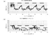
- FIG. 3 is a graph replaced with a drawing showing a pupil change and a pattern change in the example.
- FIG. 3A is a conceptual diagram showing a pupil change and a pattern display of a healthy person.
- FIG. 3B is a conceptual diagram showing pupil changes and pattern display of a patient suffering from Parkinson's disease. From FIG.
- the healthy person has a correlation with the change of the display pattern and the change of the pupil diameter over time (the pupil diameter changes in a cycle of about every 3 seconds).
- the vertical axis shows the pupil diameter and the horizontal axis shows the time.
- the pupil diameter decreased statistically with age (the older the normal pupil diameter, the smaller the swing range).
- the dominant eye was assumed to have a large pupil diameter.
- the non-dominant eye lags behind in order to see stereoscopically.
- the larger average pupil value when viewing a dark screen to a bright screen is the dominant eye.
- Brain disorders include stroke, cerebral hemorrhage (spontaneous bleeding or bleeding from head injuries), and, although less statistically, specific tumors or infections.
- Non-brain disorders that affect the sympathetic nervous system include tumors and injuries in the neck or upper chest. Horner's syndrome is a combination of three things: pupil constriction, eyelid sagging, and decreased sweating around the abnormal eye. Horner's syndrome, regardless of the cause, results from the disruption of the sympathetic nervous system that connects to the eye.
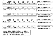
- FIG. 4 is a conceptual diagram showing a control example of a display screen for acquiring the basic pupil value.
- an initial display "Brightness changes, but please do not look away" is made, and screens of various colors are displayed for a predetermined period.
- the darkness ratio changes to 100%, 75%, 100%, 75%, 50%, 25%, 0%.
- the display time after the initial display is 7 seconds (initial display), 7 seconds, 19 seconds, 12 seconds, 12 seconds, 12 seconds and 12 seconds.
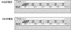
- FIG. 5 shows an example of failure (NG) when acquiring the basic pupil value (upper diagram) and an example of success (OK) (lower diagram).
- NG failure
- OK success
- the control unit stores the degree of darkness of each pattern and the measured value of the pupil diameter of the user. Then, the values of the pupil diameter are compared for each value of the darkness pattern, and if the value of the pupillary diameter is large when the value of the darkness is small (the brightness is high), it is considered to be abnormal. to decide. Then, the fact that there is an abnormality is output and detection is performed again.
- the values of the maximum pupil diameter and the minimum pupil diameter can be obtained using the case of 100% luminance and the case of 0% luminance.
- the obtained values of the maximum pupil diameter and the minimum pupil diameter are appropriately stored in the storage unit and can be used for the subsequent analysis.
- the basic pupil value may be obtained and analyzed, or the presence or absence of an affected brain disease may be analyzed using the pupil value obtained on the spot without obtaining the basic pupil value.
- FIG. 6 is a graph replaced with a drawing showing the change in the pupil diameter when black and white are displayed every one second and the change in the pupil diameter is measured. It can be seen from FIG. 6 that the change in the value of the pupil diameter changes stably and periodically in a healthy person.
- FIG. 7 is a graph replaced with a drawing showing changes in the pupil diameter when black and white are displayed every 3 seconds and changes in the pupil diameter are measured. From FIG. 7, it can be seen that the change in the value of the pupil diameter changes stably and periodically in a healthy person.
- FIG. 8 is a diagram showing measurement results of the difference between the maximum pupil diameter and the minimum pupil diameter. As shown in FIG. 8, it can be seen that the difference between the maximum pupil diameter and the minimum pupil diameter decreases as the age increases. From this, a plurality of differences between the maximum pupil diameter and the minimum pupil diameter of healthy persons of a certain age are obtained, stored in the storage unit, the stored differences are read, and statistical values such as the average value and the variance are obtained to obtain a certain age. The reference value of the difference in can be obtained. Further, it can be seen that the above-mentioned difference is smaller in patients suffering from brain-related diseases than in healthy people.
- the user can It may be possible to determine whether or not there is a risk of suffering from a brain-related disease. In this case, for example, when the actual measurement value is equal to or less than a predetermined ratio of the reference value, it may be determined that the user may have a brain-related disease.
- the numerical value related to the predetermined ratio is stored in the storage unit, and the measured value of the difference between the user, the reference value for the user's age, and the numerical value related to the predetermined ratio are read out, and the measured value of the difference between the user and the age
- the ratio of the reference values By determining the ratio of the reference values and performing an operation of comparing this ratio with a numerical value relating to a predetermined ratio, it is possible to judge whether the user may have a brain-related disease. Then, it may be possible to re-examine whether or not the patient is suffering from a brain-related disease by using the change in pupil diameter over time.
- FIG. 9 is a graph replaced with a drawing showing how the pupils of a healthy person change.
- FIG. 9 shows the pupillary change of the uppermost 46-year-old male (healthy person) in FIG.
- FIG. 10 is a graph replacing a drawing showing a change in pupil of a patient suffering from a brain disease.
- FIG. 10 shows the pupillary change of the second 76-year-old male (patient) in FIG.
- the pupil diameter changes relatively periodically from the start of measurement to the beginning (enlarged view at the bottom), but in the latter half of the measurement, the change of pupil diameter is not periodic. Therefore, it was found that the timing at which the periodicity collapses (the pattern of changes in pupil diameter over time) changes depending on the particular disease.
- pattern display is performed for 10 seconds or more (10 seconds or more and 10 minutes or less, 15 seconds or more and 5 minutes or less, or 15 seconds or more and 3 minutes or less). It was found that it is preferable to continue measuring the pupil diameter.
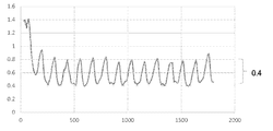
- FIG. 11 is a graph replaced with a drawing showing how the pupil changes.
- the upper part of FIG. 11 shows the pupillary change of the third 77-year-old male (patient) in FIG.
- the center of FIG. 11 shows the pupillary change of the fourth 82-year-old woman (healthy person) in FIG.
- the lower part of FIG. 11 shows the pupillary change of the fifth 84-year-old woman (patient) in FIG.
- the pupillary change of a healthy person is periodic and stable.
- the pupillary change in the patient reflects the pattern of the disease that is affected, and there are non-periodic parts.
- This invention can be used not only as a medical device but also as an application for mobile terminals.
Abstract
【解決課題】瞳孔径を観測することで,脳疾患の診断をすることができる装置を提供する。 【解決手段】表示画像制御部(3)と,撮影部(5)と,判定部(7)とを有し,表示画像制御部(3)は,第1のパターンに基づいて表示部に表示される表示画像を変化させ,撮影部(5)は,表示画像を視認するユーザの瞳孔を撮影し,判定部(7)は,撮影部が撮影したユーザの瞳孔の大きさの経時変化のパターンと,第1のパターンとを用いて,ユーザが脳疾患に罹患しているか否か判定する,脳疾患の診断装置。
Description
この発明は,脳疾患の診断装置に関する。より詳しく説明すると,この発明は,あるパターンの映像をユーザに見せた際の,ユーザの瞳孔の変化を用いて,そのユーザが脳疾患に罹っているか否かを診断する脳疾患の診断装置に関する。
国際公開WO2017-057631号パンフレットには,視認者感情判定装置が記載されている。上記の公報に記載された装置を用いれば,ユーザの呼吸,環境の明暗の影響,ユーザの脈拍といった影響を排除し,ユーザの瞳孔を撮影して,ユーザの感情を判定できる。
上記の装置のような,ユーザの瞳孔を撮影できる装置を用いた新たな装置の開発が望まれた。
この発明は,瞳孔を観察できる装置の新たな用途を提供することを目的とする。具体的に説明すると,この発明は,瞳孔径を観測することで,脳疾患の診断をすることができる装置を提供することを目的とする。
本発明は,基本的には,表示画像を変化させた際の脳障害を有するユーザの瞳孔の変化の様子は,健常人のものと異なるという知見に基づくものである。
この明細書に開示される複数の態様のうちのひとつ(第1の態様)は,脳疾患の診断装置に関する。
この脳疾患の診断装置1は,表示画像制御部3と,撮影部5と,判定部7とを有する。
表示画像制御部3は,第1のパターンに基づいて表示部に表示される表示画像を変化させるための要素である。
撮影部5は,表示画像を視認するユーザの瞳孔を撮影するための要素である。
判定部7は,撮影部が撮影したユーザの瞳孔の大きさの経時変化のパターンと,第1のパターンとを用いて,ユーザが脳疾患に罹患しているか否か判定するための要素である。
この脳疾患の診断装置1は,表示画像制御部3が,あらかじめ記憶しておいた第1のパターンに基づいて表示部に表示される表示画像を変化させる。
そして,撮影部5は,表示画像を視認するユーザの瞳孔を撮影する。
判定部7は,撮影部5が撮影した,ユーザの瞳孔を含む像を受け取る。そして,判定部7は,撮影部が撮影したユーザの瞳孔の大きさの経時変化のパターンを求め,その経時変化のパターンと,第1のパターンとを用いて,ユーザが脳疾患に罹患しているか否か判定する。例えば,ユーザの瞳孔の大きさの経時変化のパターンと,第1のパターンとの間に相関がある場合に,ユーザは健常人であると判断するようにしてもよい。ユーザの瞳孔の大きさの経時変化のパターンは,優位眼及び非優位眼の瞳孔の大きさの差の経時変化のパターンを含むものであることが好ましい。
この装置は,所定の時間パターンに基づいて変動する第1のパターンに基づいて表示部に表示される表示画像を変化させる表示画像制御部と,表示画像を視認するユーザの瞳孔を撮影する撮影部と,撮影部が撮影したユーザの瞳孔の大きさの経時変化のパターンと,第1のパターンの所定の時間パターンに関する情報とを用いて,ユーザが脳疾患に罹患しているか否か判定する判定部と,を有する,脳疾患の診断装置であってもよい。
第1のパターンは,例えば,輝度,色彩,及び明度のうちいずれか1つ又は2つ以上が,所定の時間パターンに基づいて変動するものである。第1のパターンの具体例は,周期的に変化する白画面及び黒画面である。この装置は,ユーザの年齢情報を記憶する年齢記憶部をさらに有するものが好ましい。そして,表示画面制御部3は,年齢記憶部が記憶したユーザの年齢情報に基づいて,所定の時間パターンを制御するものが好ましい。
脳疾患の例は,てんかん,神経変性疾患,神経幹細胞疾患,神経前駆細胞疾患,虚血性疾患,神経性外傷,情動障害,神経精神疾患,網膜変性疾患,網膜損傷/外傷,認知・学習・記憶障害,アルツハイマー病,軽度認知障害(MCI),パーキンソン病,パーキンソン症候群,ハンチントン病,筋萎縮性側索硬化症,虚血性脳卒中,外傷性脳損傷,鬱病,双極性鬱病/障害,慢性疲労症候群,不安症候群/障害,自閉症,又はアスペルガー症候群である。この装置は,機械学習された予測アルゴリズムに従って,前記脳疾患の診断を行う,脳疾患の診断装置であることが好ましい。
この発明によれば,比較的簡便な装置(例えば,瞳孔を撮影できる装置とコンピュータ)を用いるだけで,ユーザが脳疾患に罹患しているか,脳疾患が重度か,罹患するリスクが高いかといった診断をすることができる装置を提供できる。
以下,図面を用いて本発明を実施するための形態について説明する。本発明は,以下に説明する形態に限定されるものではなく,以下の形態から当業者が自明な範囲で適宜修正したものも含む。
この明細書に開示される複数の態様のうちのひとつ(第1の態様)は,脳疾患の診断装置に関する。脳疾患の診断装置は,ユーザが脳疾患に罹患しているか,脳疾患の程度が重度か,罹患するリスクが高いかのいずれか1つ以上を判定するためのコンピュータを用いた装置である。
脳疾患の例は,てんかん,神経変性疾患,神経幹細胞疾患,神経前駆細胞疾患,虚血性疾患,神経性外傷,情動障害,神経精神疾患,網膜変性疾患,網膜損傷/外傷,認知・学習・記憶障害,アルツハイマー病,軽度認知障害(MCI),パーキンソン病,パーキンソン症候群,ハンチントン病,筋萎縮性側索硬化症,虚血性脳卒中,外傷性脳損傷,鬱病,双極性鬱病/障害,慢性疲労症候群,不安症候群/障害,自閉症,又はアスペルガー症候群である。
図1-1は,脳疾患の診断装置の構成を説明するための概念図である。図1-1に示されるように,この脳疾患の診断装置1は,表示画像制御部3と,撮影部5と,判定部7とを有する。表示画像制御部3は,第1のパターンに基づいて表示部に表示される表示画像を変化させるための要素である。表示部の例は,モニタ,画面,及び映写用の壁である。
この装置は,カメラなどの撮影装置と情報のやり取りができるようにされたコンピュータにより実装できる。カメラなどによる撮影情報は,ケーブルなどを通してコンピュータに入力されてもよい。また,撮影情報は,無線により,コンピュータに入力されてもよい。コンピュータは,入出力部,制御部,演算部及び記憶部を含み,各要素はバスなどにより情報の授受を行うことができるようにされている。そして,コンピュータは,入力された情報を,記憶部に記憶する。また,コンピュータの制御部は,記憶部に記憶した制御プログラムを読み出し,入力された情報や,記憶部に記憶された情報を用いて,演算部に各種演算を行わせる。そして,演算結果は,適宜記憶部に記憶されるとともに,入出力部を介して,適宜出力される。
第1のパターンは,例えば,輝度,色彩,及び明度のうちいずれか1つ又は2つ以上が,所定の時間パターンに基づいて変動するものである。パターンが2種類の画面(映像)を含む場合,切り替えの頻度の例は1秒以上10秒以下であり,2秒以上6秒以下でも,2秒以上5秒以下でもよい。切り替えは,一定の時間ごとでもよい。また,第1の画面(例えば白画面)と第2の画面(例えば黒画面)については,それぞれ異なる秒数ごとに切り替えを行ってもよい。このパターンは,例えば,3種類以上の画面が切り替えられるものであってもよい。
図2は,第1のパターンの例を示す概念図である。図2(a)は,一定の時間ごとに,白画面及び黒画面が交互に表示されるものを示す。図2(b)は,一定のパターンで白画面,映像画面,及び所定の輝度の画面が表示されるものの例を示す。
撮影部5は,表示画像を視認するユーザの瞳孔を撮影するための要素である。国際公開WO2017-057631号パンフレット(特許文献1)には,カメラなどの撮影部を含む瞳孔径計測器が記載されているので,瞳孔径計測器を用いてもよい。
図1-2は,脳疾患の診断装置の構成を説明するための概念図である。撮影部5が3つの撮影要素を含む。この例では,中央のカメラ(撮影素子)5aと,その両端のカメラ(撮影素子)5b,5cを含む。この例では,カメラ5bとカメラ5cにより,片方の眼球を画像認識で追尾して捉え,カメラ5bとカメラ5cの間の距離と眼球への角度を用いて,三角測量より,カメラ5bとカメラ5cの真ん中のカメラ5aから眼球までの距離を算出する。5aのカメラで撮影された瞳孔径は距離により大きさが異なるので,5aにより撮影された瞳孔径を5aからの距離により,瞳孔径の測定値を補正する。これにより顔が少々動いても、正確な瞳孔径を求めることができる。
瞳孔は,眼球の中央部分のうち光を通す領域である。瞳孔は,光等の影響を受け大きさが変化する。一方,瞳孔は,瞳孔の周囲部分の虹彩とは色が異なる。このため,あるユーザの複数の眼球像を撮影し,大きさが変化する領域を分析し,その部分の色(色の幅)を記憶する。このようにすることで,そのユーザの瞳孔色を記憶できる。そして,そのユーザの瞳孔を含む映像を撮影し,色味を分析する。すると,連続して色の領域が存在する。その領域のうち,およそ中央に位置する領域であるか,先の瞳孔の色と一致する領域が,瞳孔の領域であり、その瞳孔径を測定できる。
判定部7は,撮影部が撮影したユーザの瞳孔の大きさの経時変化のパターンと,第1のパターンとを用いて,ユーザが脳疾患に罹患しているか否か判定するための要素である。
判定部7は,例えば,上記したアルゴリズムに基づいて,ユーザの瞳孔の大きさを経時的に求める。そして,判定部7は,ある時間分のユーザの瞳孔の大きさの変化について,変化瞳孔を分析する。例えば,ある時間分のユーザの瞳孔の大きさについて,増加傾向にあるか,減少傾向にあるか,変化量が一定幅といえるかを求める。このようにして,判定部は,ユーザの瞳孔の大きさの変化状況を分析できる。
また,判定部7は,ある時間分のユーザの瞳孔の最大値と最小値とを求め,さらにその差Δを求める。この瞳孔は優位眼及び非優位眼のいずれかのものでもよいし,両方でもよい。そして,最大値から一定の範囲(例えば0.2mmΔ以上0.5mmΔの範囲)の部分(上部分)と,最小値から一定の範囲(例えば0.2mmΔ以上0.5mmΔの範囲)の部分(下部分)のいずれか又は両方を求め,上部分と下部分のいずれか又は両方の出現頻度と,第1のパターンとに相関があるか検討してもよい。例えば,下部分が,第1のパターンの変化頻度と同じ頻度(又は一定時間以内のずれ)で出現すれば,そのユーザは健常人と判断してもよい。この処理は,撮影部が撮影した映像から,画像解析によりユーザの瞳孔部分を抽出する。そして,画像に含まれる左右2つの瞳孔部分について,相対的な大きさを求め,記憶部に記憶する。演算部は,記憶部に記憶された左右それぞれの瞳孔の大きさの情報を読み出し,それらの経時変化を求める。すると,制御部は,瞳孔の大きさの最大値を与える時間と最小値を与える時間,瞳孔の大きさが大きくなる時間領域及び瞳孔の大きさが小さくなる時間領域,及び瞳孔の大きさの変動が一定の範囲である時間領域を分析することができる。このようにすれば,瞳孔の大きさの最大値及び最小値を求めることや,瞳孔の大きさの時間変化のパターンを求めることができる。
また,上記のユーザの瞳孔の経時変化と,第1のパターンとの相関が低ければ,脳疾患の程度が高くなるように判定してもよいし,相関係数といった指標が一定範囲であれば,脳疾患に罹患するリスクがあると判定してもよい。
ユーザの瞳孔の大きさの経時変化のパターンは,優位眼及び非優位眼の瞳孔の大きさの差の経時変化のパターンを含むものであることが好ましい。この装置は,暗い画面から明るい画面に変化した後における明るい画面が表示されている状況に対応した瞳孔の大きさの平均値が大きい方の目を優位眼としてもよい。手の親指と人差し指で輪を作り、両目である目標物を見て、手で作った輪にその目標物が入るようにする。そのまま、片目ずつ閉じて、開いていている方の目で対象物を見て、輪の中に入っている目を優位眼としてもよい。反対に輪の中に入っていない目を非優位眼としてもよい。一般的に,明るい画面を視認している状況の方が,瞳孔が小さくなる。このためユーザが暗い画面を見ているか明るい画面を見ているかを把握することはできる。一方,画面が変わっても瞳孔の大きさの変化にはラグ(時間遅延:ディレイ)があるので,明るい画面が表示されている状況に対応した瞳孔の大きさは,画面自体が明るい状況に変わっても瞳孔径の変化が追い付いていない状態がある。画面自体が暗い状態から明るい状況に変化した際は、しばらく瞳孔径が大きい状態から小さい状態に変化するが、その瞳孔の変化する経過も含まれる。
コンピュータは,記憶部に,各種疾患とそれに対応した瞳孔の変化を記憶していてもよい。また,コンピュータは,複数の疾患について,複数の患者の瞳孔の変化を撮影し,各疾患と瞳孔の変化の経時変化を機械学習させておき,各種疾患と瞳孔の経時変化に関するデータベースを構築しておいてもよい。すると,判定部7は,撮影部5が撮影したユーザの瞳孔を含む像を用いて,ユーザの瞳孔の経時変化を求め,パターニングすることにより,そのユーザが脳疾患に罹患しているか,脳疾患が重度か,罹患するリスクが高いかといった診断をすることができる。
この装置は,ユーザの年齢情報を記憶する年齢記憶部9をさらに有するものが好ましい。そして,表示画面制御部3は,年齢記憶部が記憶したユーザの年齢情報に基づいて,所定の時間パターンを制御するものが好ましい。これは,ユーザ(被験者)が高齢となるほど短い画面秒数の変化に対し反応異常が表出しやすいという実験結果に基づくものである。例えば,ユーザの年齢逆数を係数として,表示間隔時間に乗算することで,年齢が高いユーザ程,表示を切り替える時間間隔が短くなるように制御するか,少なくとも,一定の年齢以上のユーザに対しては,通常の表示モードの他,短時間で表示を切り替える短時間切り替えモードをも用意することが好ましい。コンピュータが,年齢記憶部からユーザの年齢に関する情報を読み出し,記憶部から閾値を読み出して,年齢と閾値とを比べ,ユーザの年齢が閾値を超えていれば,短時間切り替えモードとするか,少なくとも短時間切り替えモードをも表示するように制御すればよい。なお,この装置は,各種処理(例えば機械学習処理)などを行うための情報処理部11をさらに有していてもよい。
この脳疾患の診断装置1は,
表示画像制御部3が,あらかじめ記憶しておいた第1のパターンに基づいて表示部に表示される表示画像を変化させる。
そして,撮影部5は,表示画像を視認するユーザの瞳孔を撮影する。
判定部7は,撮影部5が撮影した,ユーザの瞳孔を含む像を受け取る。そして,判定部7は,撮影部が撮影したユーザの瞳孔の大きさの経時変化のパターンを求め,その経時変化のパターンと,第1のパターンとを用いて,ユーザが脳疾患に罹患しているか否か判定する。判定部7は,さらに,脳疾患が重度か,罹患するリスクが高いかといった診断も行えるようにすることが好ましい。この装置は,機械学習された予測アルゴリズムに従って,前記脳疾患の診断を行う,脳疾患の診断装置であることが好ましい。個別の脳疾患についての瞳孔の経時変化に関するデータをシステムに入力する。そして,入力された各種データを機械学習することで,各疾患と,経時変化のパターンや第1のパターンとの相関等を解析させることができる。このようにして機械学習された予測アルゴリズムを得ることができる。そして,機械学習された予測アルゴリズムを用いることで,脳疾患の各疾患の診断を行うことができることとなる。さらに機械学習を重ねることにより、個々の疾患の瞳孔径の変化のパターンを学習し、個々の脳疾患を予測できる。
この明細書は,コンピュータを,
第1のパターンに基づいて表示部に表示される表示画像を変化させる手段と,
撮影部が撮影した,表示画像を視認するユーザの瞳孔の撮影画像を受け取る手段と,
受け取った瞳孔の撮影画像を用いて,撮影部が撮影したユーザの瞳孔の大きさの経時変化のパターンを求め,求めた瞳孔の大きさの経時変化のパターンと第1のパターンとを用いて,ユーザが脳疾患に罹患しているか否か判定するための手段と,
して機能させるプログラムをも提供する。このプログラムは,さらにコンピュータを上記した脳疾患の診断装置の各機能を実現するものであってもよい。
第1のパターンに基づいて表示部に表示される表示画像を変化させる手段と,
撮影部が撮影した,表示画像を視認するユーザの瞳孔の撮影画像を受け取る手段と,
受け取った瞳孔の撮影画像を用いて,撮影部が撮影したユーザの瞳孔の大きさの経時変化のパターンを求め,求めた瞳孔の大きさの経時変化のパターンと第1のパターンとを用いて,ユーザが脳疾患に罹患しているか否か判定するための手段と,
して機能させるプログラムをも提供する。このプログラムは,さらにコンピュータを上記した脳疾患の診断装置の各機能を実現するものであってもよい。
この明細書は,コンピュータを,
第1のパターンに基づいて表示部に表示される表示画像を変化させる工程と,
撮影部が撮影した,表示画像を視認するユーザの瞳孔の撮影画像を受け取る工程と,
受け取った瞳孔の撮影画像を用いて,撮影部が撮影したユーザの瞳孔の大きさの経時変化のパターンを求め,求めた瞳孔の大きさの経時変化のパターンと第1のパターンとを用いて,ユーザが脳疾患に罹患しているか否か判定する工程と,
を行わせるプログラムをも提供する。このプログラムは,さらにコンピュータを上記した脳疾患の診断装置の各機能を実現するものであってもよい。
第1のパターンに基づいて表示部に表示される表示画像を変化させる工程と,
撮影部が撮影した,表示画像を視認するユーザの瞳孔の撮影画像を受け取る工程と,
受け取った瞳孔の撮影画像を用いて,撮影部が撮影したユーザの瞳孔の大きさの経時変化のパターンを求め,求めた瞳孔の大きさの経時変化のパターンと第1のパターンとを用いて,ユーザが脳疾患に罹患しているか否か判定する工程と,
を行わせるプログラムをも提供する。このプログラムは,さらにコンピュータを上記した脳疾患の診断装置の各機能を実現するものであってもよい。
このプログラムは,例えば,スマートフォンなどの携帯端末や,ゲーム機にインストールすることで,スマートフォンなどを用いて,簡易な,脳診断ツールを提供できる。
この明細書は,上記のプログラムを記憶した,コンピュータが読み取ることができる情報記録媒体であってもよい。情報記録媒体の例は,CD-ROM,DVD,メモリスティックである。
以下,実施例を用いて,本発明を具体的に説明する。本発明は,以下の実施例に限定されるものではない。
コンピュータを,実験開始後,モニタが白画面及び黒画面を3秒ごとに表示するようにした。また,対象の瞳孔を撮影できるカメラを用意した。また,撮影画像から,対象の瞳孔の変化を分析できるようにプログラムを組んだ。なお,この例では,対象の瞳孔径の絶対的な大きさを求めることができるようにした。
図3は,実施例における瞳孔変化とパターン変化を示す図面に替わるグラフである。 図3(a)は,健常人の瞳孔変化とパターン表示を示す概念図である。一方,図3(b)は,パーキンソン病に罹患している患者の,瞳孔変化とパターン表示を示す概念図である。
図3(a)から,健常人は,表示パターンの変化と,瞳孔径の経時変化とに相関がある(およそ3秒ごとの周期で瞳孔径が変動している)ことがわかる。
図3(b)から,パーキンソン病に罹患した患者からは,表示パターンの変化と,瞳孔径の経時変化とに相関がないことがわかる。グラフにおいて縦軸は瞳孔径,横軸は時間を示す。
図3は,実施例における瞳孔変化とパターン変化を示す図面に替わるグラフである。 図3(a)は,健常人の瞳孔変化とパターン表示を示す概念図である。一方,図3(b)は,パーキンソン病に罹患している患者の,瞳孔変化とパターン表示を示す概念図である。
図3(a)から,健常人は,表示パターンの変化と,瞳孔径の経時変化とに相関がある(およそ3秒ごとの周期で瞳孔径が変動している)ことがわかる。
図3(b)から,パーキンソン病に罹患した患者からは,表示パターンの変化と,瞳孔径の経時変化とに相関がないことがわかる。グラフにおいて縦軸は瞳孔径,横軸は時間を示す。
左右の瞳孔径の差はある程度必ずある。実験の結果,統計的に,この差が大きいと特定の疾患に罹患している可能性が高いことが分かった。また,実験の結果,統計的に,年齢と共に瞳孔径は小さくなる(高齢者ほど通常の瞳孔径が小さい。振れ幅が少ない)ことが分かった。一般的に優位眼(利き目)は瞳孔径が大きいと推測した。優位眼(利き目)があるものを見る場合に先に到達、非優位眼は遅れて立体視するために追随する。基本瞳孔値判定において暗い画面から明るい画面を見ている際の平均瞳孔値の大きい方が利き目であると仮定した。実験の結果,特定の脳疾患に罹患している患者は,明順応時間と暗順応時間の変化時に瞳孔径を制御する自律神経「交感神経(散大・暗い画面)、副交感神経(縮瞳・明るい画面)」に短時間で異常な変化が見られることが分かった。また,時間的に高齢になるほど短い画面秒数の変化に反応異常が表出しやすいことも分かった。
万人のデータを比較する際に、基本瞳孔値を得ることで、比較できるデータとなると考えられる。
優位眼と非優位眼の変化(視線位置への追随の差)・優位眼と非優位眼の明暗画面を見る際の時間と瞳孔径の変化の組み合わせで健常者平均値との差異が大きい場合,異常である(特定疾患に罹患している)と判定できる。個別に精査することで特定の病気の解析結果パターンが判明する。
万人のデータを比較する際に、基本瞳孔値を得ることで、比較できるデータとなると考えられる。
優位眼と非優位眼の変化(視線位置への追随の差)・優位眼と非優位眼の明暗画面を見る際の時間と瞳孔径の変化の組み合わせで健常者平均値との差異が大きい場合,異常である(特定疾患に罹患している)と判定できる。個別に精査することで特定の病気の解析結果パターンが判明する。
左右の瞳孔の大きさが異なることについて,原因となる神経系疾患には,これまでの実験からみて,脳神経の病気のほか,交感神経系または副交感神経系(自律神経系)の一部の異常がある。脳疾患には,脳卒中,脳出血(自然な出血または頭部のけがによる出血)のほか,統計的な頻度は下がるものの,特定の腫瘍または感染症などがある。交感神経系に影響を及ぼす脳以外の病気には,首または胸の上部の腫瘍やけがなどがある。ホルネル症候群は,瞳孔の収縮,まぶたの垂れ下がり及び異常のある方の眼の周りの発汗減少という3つが組み合わさった症状である。ホルネル症候群は、原因にかかわらず、眼につながる交感神経系が分断されることで起こる。
図4は,基本瞳孔値を取得するための表示画面の制御例を示す概念図である。この例では,最初に,「明るさが変わりますが,目をそらさないで下さい」という初期表示がなされ,様々な色みの画面が所定期間表示される。暗さの割合が,100%、75%,100%,75%、50%,25%,0%と変化している。初期表示以降の表示時間は,7秒(初期表示),7秒,19秒,12秒,12秒,12秒及び12秒である。
図5は,基本瞳孔値を取得する際の失敗(NG)の例(上図)及び成功(OK)の例(下図)を示す例である。上図の例では暗さが50%の際に,暗さが75%のものよりも瞳孔径が大きくなっているので,異常値と判断される。つまり,制御部は,各パターンの暗さ度及び測定したユーザの瞳孔径の値を記憶する。そして,暗さのパターンの値ごとに瞳孔径の値を比較し,暗さの値が小さい(輝度が高い)場合に,瞳孔径の値が大きくなっているものがあれば,異常であると判断する。そして,異常である旨を出力し,再度検出を行う。成功の場合は,輝度100%の場合と,0%の場合とを用いて,最大瞳孔径及び最小瞳孔径の値を得ることができる。得られた最大瞳孔径及び最小瞳孔径の値は,適宜記憶部に記憶され,後の解析に用いることができる。なお,基本瞳孔値を求めて解析を行ってもよいし,基本瞳孔値を求めずに,その場で得られた瞳孔値を用いて,罹患の脳疾患有無の解析を行ってもよい。
健常者であるユーザに,黒及び白を1秒ごとに表示を行い瞳孔径の変化を測定した。その結果を図6に示す。図6は,黒及び白を1秒ごとに表示を行い瞳孔径の変化を測定した際の瞳孔径の変化を示す図面に替わるグラフである。図6から,健常人では,瞳孔径の値の変化が,周期的に安定して変化することが分かる。
健常者であるユーザに,黒及び白を3秒ごとに表示を行い瞳孔径の変化を測定した。その結果を図7に示す。図7は,黒及び白を3秒ごとに表示を行い瞳孔径の変化を測定した際の瞳孔径の変化を示す図面に替わるグラフである。図7から,健常人では,瞳孔径の値の変化が,周期的に安定して変化することが分かる。
複数の者に対し,最大瞳孔径と最小瞳孔径の差を求めた。図8は,最大瞳孔径と最小瞳孔径の差の測定結果を示す図である。図8に示されるように,年齢が高くなるほど,最大瞳孔径と最小瞳孔径の差が小さくなることが分かる。このことから,ある年齢の健常人の最大瞳孔径と最小瞳孔径の差を複数求めて記憶部に記憶し,記憶した差を読み出して,平均値や分散といった統計値を求めることで,ある年齢における差の基準値を求めることができることとなる。また,脳関連の疾患に罹患している患者は,健常人に比べて上記の差が小さいことが分かる。このため,ある年齢における差の基準値と,ユーザの年齢情報及び測定した差を記憶部から読み出し,ユーザの年齢における差の基準値と,測定した差の値とを比較することで,ユーザが脳関連疾患に罹患している恐れがあるか否かを判断するようにしてもよい。この場合,例えば,上記実測値が上記基準値の所定割合以下の場合に,ユーザが脳関連疾患に罹患している恐れがあると判断してもよい。この場合,所定割合に関する数値を記憶部に記憶しておき,ユーザの差の実測値,ユーザの年齢における基準値,及び所定割合に関する数値を読み出して,ユーザの差の実測値とユーザの年齢における基準値の比を求め,この比と所定割合に関する数値とを比較する演算を行うことで,ユーザが脳関連疾患に罹患している恐れがあるか判断できる。そのうえで,瞳孔径の経時変化を用いて,脳関連疾患に罹患しているか否か、さらにその程度を再検討するようにしてもよい。
黒白画面を1秒間交互に30秒間表示した際の瞳孔径の変化を測定した。
図9は,健常者の瞳孔変化の様子を示す図面に替わるグラフである。図9は,図8における一番上の46歳男性(健常者)の瞳孔変化を示すものである。
図9は,健常者の瞳孔変化の様子を示す図面に替わるグラフである。図9は,図8における一番上の46歳男性(健常者)の瞳孔変化を示すものである。
図10は,脳疾患に罹患している患者の瞳孔変化の様子を示す図面に替わるグラフである。図10は,図8における二番目の76歳男性(患者)の瞳孔変化を示すものである。図10に示される例では,測定開始から最初のうちは比較的周期的に瞳孔径が変化するものの(下部拡大図),測定後半になると,瞳孔径の変化が周期的ではなくなった。このため,特定の疾患により,周期性のくずれるタイミング(瞳孔径の経時変化のパターン)に変化があることが分かった。また,この実施例から,全ての脳関連疾患の診断をする場合は,例えば10秒以上(10秒以上10分以下,15秒以上5分以下,又は15秒以上3分以下)パターン表示を行い,瞳孔径を測定し続けることが好ましいことが分かった。
図11は,瞳孔変化の様子を示す図面に替わるグラフである。図11の上は,図8における三番目の77歳男性(患者)の瞳孔変化を示すものである。図11の中央は,図8における四番目の82歳女性(健常者)の瞳孔変化を示すものである。図11の下は,図8における五番目の84歳女性(患者)の瞳孔変化を示すものである。図11に示されるように,健常者の瞳孔変化は周期的で安定している。一方,患者の瞳孔変化は,罹患している疾患のパターンを反映し,周期的でない部分が存在している。
この発明は,医療機器として利用され得る他,携帯端末用のアプリケーションとしても利用され得る。
1 脳疾患の診断装置
3 表示画像制御部
5 撮影部
7 判定部
11 年齢記憶部
3 表示画像制御部
5 撮影部
7 判定部
11 年齢記憶部
Claims (9)
- 所定の時間パターンに基づいて変動する第1のパターンに基づいて表示部に表示される表示画像を変化させる表示画像制御部と,
前記表示画像を視認するユーザの瞳孔を撮影する撮影部と,
前記撮影部が撮影した前記ユーザの瞳孔の大きさの経時変化のパターンと,第1のパターンの前記所定の時間パターンに関する情報とを用いて,前記ユーザが脳疾患に罹患しているか否か判定する判定部と,
を有する,脳疾患の診断装置。 - 請求項1に記載の脳疾患の診断装置であって,
第1のパターンは,輝度,色彩,及び明度のうちいずれか1つ又は2つ以上が,所定の時間パターンに基づいて変動するものである,装置。 - 請求項2に記載の脳疾患の診断装置であって,
前記ユーザの年齢情報を記憶する年齢記憶部をさらに有し,
前記表示画面制御部は,前記年齢記憶部が記憶した前記ユーザの年齢情報に基づいて,前記所定の時間パターンを制御する,装置。 - 請求項1に記載の脳疾患の診断装置であって,
第1のパターンは,周期的に変化する白画面及び黒画面である,装置。 - 請求項1に記載の脳疾患の診断装置であって,
前記ユーザの瞳孔の大きさの経時変化のパターンと,第1のパターンの所定の時間パターンとの間に相関がある場合に,前記ユーザは健常人であると判断する,装置。 - 請求項1に記載の脳疾患の診断装置であって,
前記ユーザの瞳孔の大きさの経時変化のパターンは,優位眼及び非優位眼の瞳孔の大きさの差の経時変化のパターンを含む,装置。 - 請求項1に記載の脳疾患の診断装置であって,
前記脳疾患は,てんかん,神経変性疾患,神経幹細胞疾患,神経前駆細胞疾患,虚血性疾患,神経性外傷,情動障害,神経精神疾患,網膜変性疾患,網膜損傷/外傷,認知・学習・記憶障害,アルツハイマー病,軽度認知障害(MCI),パーキンソン病,パーキンソン症候群,ハンチントン病,筋萎縮性側索硬化症,虚血性脳卒中,外傷性脳損傷,鬱病,双極性鬱病/障害,慢性疲労症候群,不安症候群/障害,自閉症,又はアスペルガー症候群である,装置。 - 請求項7に記載の脳疾患の診断装置であって,
各種の脳疾患に罹患した患者の瞳孔の大きさの経時変化のパターンである患者経時変化パターンを受け取る経時変化パターン入力部と,
前記患者経時変化パターンに基づき,各種の脳疾患に罹患した患者の経時変化のパターンを機械学習する経時変化のパターン機械学習部と,をさらに含み,
前記判定部は,
前記経時変化のパターン機械学習部が学習した各種の脳疾患に罹患した患者の経時変化のパターンに基づいて,対象となる脳疾患に罹患していることを判定する,
脳疾患の診断装置。 - 請求項7に記載の脳疾患の診断装置であって,
機械学習された予測アルゴリズムに従って,前記脳疾患の診断を行う,
脳疾患の診断装置。
Priority Applications (6)
| Application Number | Priority Date | Filing Date | Title |
|---|---|---|---|
| CN201980083541.6A CN113194840A (zh) | 2018-12-17 | 2019-12-13 | 脑疾病的诊断装置 |
| EP19900976.2A EP3900638A4 (en) | 2018-12-17 | 2019-12-13 | BRAIN DISEASE DIAGNOSTIC DEVICE |
| US17/414,333 US20220054076A1 (en) | 2018-12-17 | 2019-12-13 | Device for Diagnosing Brain Disease |
| KR1020217019421A KR20210104738A (ko) | 2018-12-17 | 2019-12-13 | 뇌 질환 진단 장치 |
| JP2020561375A JP7396681B2 (ja) | 2018-12-17 | 2019-12-13 | 脳疾患の診断装置 |
| SG11202106430YA SG11202106430YA (en) | 2018-12-17 | 2019-12-13 | Device for diagnosing brain disease |
Applications Claiming Priority (2)
| Application Number | Priority Date | Filing Date | Title |
|---|---|---|---|
| JP2018235105 | 2018-12-17 | ||
| JP2018-235105 | 2018-12-17 |
Publications (1)
| Publication Number | Publication Date |
|---|---|
| WO2020129834A1 true WO2020129834A1 (ja) | 2020-06-25 |
Family
ID=71102127
Family Applications (1)
| Application Number | Title | Priority Date | Filing Date |
|---|---|---|---|
| PCT/JP2019/048894 WO2020129834A1 (ja) | 2018-12-17 | 2019-12-13 | 脳疾患の診断装置 |
Country Status (7)
| Country | Link |
|---|---|
| US (1) | US20220054076A1 (ja) |
| EP (1) | EP3900638A4 (ja) |
| JP (1) | JP7396681B2 (ja) |
| KR (1) | KR20210104738A (ja) |
| CN (1) | CN113194840A (ja) |
| SG (1) | SG11202106430YA (ja) |
| WO (1) | WO2020129834A1 (ja) |
Cited By (3)
| Publication number | Priority date | Publication date | Assignee | Title |
|---|---|---|---|---|
| WO2022186586A1 (ko) * | 2021-03-02 | 2022-09-09 | 주식회사 메디셀 | 질환 진단 장치 및 질환 진단 방법 |
| KR20220124066A (ko) | 2021-03-02 | 2022-09-13 | 주식회사 메디셀 | 질환 진단 장치 및 질환 진단 방법 |
| WO2023214535A1 (ja) * | 2022-05-02 | 2023-11-09 | Kikura株式会社 | 左右の目で独立した表示画像を目視することによる脳疾患又は自立神経失調症の診断装置及びプログラム |
Citations (7)
| Publication number | Priority date | Publication date | Assignee | Title |
|---|---|---|---|---|
| JP2002034920A (ja) * | 2000-05-15 | 2002-02-05 | Matsushita Electric Works Ltd | 脳機能検査方法及び脳機能検査装置 |
| JP2002282208A (ja) * | 2001-03-22 | 2002-10-02 | Munetaka Haida | 痴呆症診断装置 |
| JP2002541959A (ja) * | 1999-04-23 | 2002-12-10 | ニューロプティックス・インコーポレイテッド | 瞳孔不規則性検出・瞳孔追跡・瞳孔反応検出機能、緑内障検査機能、角膜解剖学的測定機能、頭蓋内圧検出機能、および、眼異常測定機能を備えた瞳孔計 |
| JP2003070753A (ja) * | 2001-09-06 | 2003-03-11 | Scalar Corp | 診断システム、診断データ生成方法、それに用いられる情報処理装置、及び端末装置、並びに記録媒体 |
| JP2016504089A (ja) * | 2012-12-11 | 2016-02-12 | クライン、アミKLIN, Ami | エンゲージメント及び知覚刺激顕著性のマーカーとして瞬き抑制を検出するためのシステム及び方法 |
| WO2017057631A1 (ja) | 2015-10-01 | 2017-04-06 | 株式会社夏目綜合研究所 | 明暗、呼吸及び脈拍の影響を排除する視認者情感判定装置、視認者情感判定システム及びプログラム |
| JP2017184996A (ja) * | 2016-04-05 | 2017-10-12 | 渡 倉島 | 瞳孔径拡大による脳活動量判定装置およびプログラム |
Family Cites Families (9)
| Publication number | Priority date | Publication date | Assignee | Title |
|---|---|---|---|---|
| JP4883580B2 (ja) * | 2007-06-05 | 2012-02-22 | 独立行政法人産業技術総合研究所 | 精神的疲労の検出方法、装置及びプログラム |
| JP5817582B2 (ja) * | 2012-02-22 | 2015-11-18 | 株式会社Jvcケンウッド | 脳機能疾患診断支援装置および脳機能疾患診断支援方法 |
| WO2015164807A1 (en) * | 2014-04-25 | 2015-10-29 | Texas State University | Detection of brain injury and subject state with eye movement biometrics |
| JP6562077B2 (ja) * | 2015-08-20 | 2019-08-21 | 日本電気株式会社 | 展示装置、表示制御装置および展示システム |
| US20180190011A1 (en) * | 2017-01-04 | 2018-07-05 | Osterhout Group, Inc. | Content rendering systems for head-worn computers |
| JP7017002B2 (ja) * | 2016-06-16 | 2022-02-08 | ハダシット メディカル リサーチ サービシズ アンド ディベラップメント リミテッド | 眼瞼を閉じた対象者における瞳孔の大きさを決定するための装置および方法 |
| JP6311002B1 (ja) * | 2016-12-28 | 2018-04-11 | 株式会社ブレインウェイ | 視覚利用脳トレーニングシステム |
| SG10201703570YA (en) * | 2017-05-02 | 2018-12-28 | Singapore Health Serv Pte Ltd | Hand held ophthalmic and neurological screening device |
| KR20190108727A (ko) * | 2018-03-15 | 2019-09-25 | 민상규 | 접이식 가상현실 장비 |
-
2019
- 2019-12-13 JP JP2020561375A patent/JP7396681B2/ja active Active
- 2019-12-13 KR KR1020217019421A patent/KR20210104738A/ko not_active Application Discontinuation
- 2019-12-13 EP EP19900976.2A patent/EP3900638A4/en active Pending
- 2019-12-13 CN CN201980083541.6A patent/CN113194840A/zh active Pending
- 2019-12-13 SG SG11202106430YA patent/SG11202106430YA/en unknown
- 2019-12-13 WO PCT/JP2019/048894 patent/WO2020129834A1/ja unknown
- 2019-12-13 US US17/414,333 patent/US20220054076A1/en active Pending
Patent Citations (7)
| Publication number | Priority date | Publication date | Assignee | Title |
|---|---|---|---|---|
| JP2002541959A (ja) * | 1999-04-23 | 2002-12-10 | ニューロプティックス・インコーポレイテッド | 瞳孔不規則性検出・瞳孔追跡・瞳孔反応検出機能、緑内障検査機能、角膜解剖学的測定機能、頭蓋内圧検出機能、および、眼異常測定機能を備えた瞳孔計 |
| JP2002034920A (ja) * | 2000-05-15 | 2002-02-05 | Matsushita Electric Works Ltd | 脳機能検査方法及び脳機能検査装置 |
| JP2002282208A (ja) * | 2001-03-22 | 2002-10-02 | Munetaka Haida | 痴呆症診断装置 |
| JP2003070753A (ja) * | 2001-09-06 | 2003-03-11 | Scalar Corp | 診断システム、診断データ生成方法、それに用いられる情報処理装置、及び端末装置、並びに記録媒体 |
| JP2016504089A (ja) * | 2012-12-11 | 2016-02-12 | クライン、アミKLIN, Ami | エンゲージメント及び知覚刺激顕著性のマーカーとして瞬き抑制を検出するためのシステム及び方法 |
| WO2017057631A1 (ja) | 2015-10-01 | 2017-04-06 | 株式会社夏目綜合研究所 | 明暗、呼吸及び脈拍の影響を排除する視認者情感判定装置、視認者情感判定システム及びプログラム |
| JP2017184996A (ja) * | 2016-04-05 | 2017-10-12 | 渡 倉島 | 瞳孔径拡大による脳活動量判定装置およびプログラム |
Cited By (4)
| Publication number | Priority date | Publication date | Assignee | Title |
|---|---|---|---|---|
| WO2022186586A1 (ko) * | 2021-03-02 | 2022-09-09 | 주식회사 메디셀 | 질환 진단 장치 및 질환 진단 방법 |
| KR20220124066A (ko) | 2021-03-02 | 2022-09-13 | 주식회사 메디셀 | 질환 진단 장치 및 질환 진단 방법 |
| KR102547769B1 (ko) * | 2021-03-02 | 2023-06-27 | 주식회사 메디셀 | 질환 진단 장치 |
| WO2023214535A1 (ja) * | 2022-05-02 | 2023-11-09 | Kikura株式会社 | 左右の目で独立した表示画像を目視することによる脳疾患又は自立神経失調症の診断装置及びプログラム |
Also Published As
| Publication number | Publication date |
|---|---|
| SG11202106430YA (en) | 2021-07-29 |
| JPWO2020129834A1 (ja) | 2020-06-25 |
| EP3900638A1 (en) | 2021-10-27 |
| KR20210104738A (ko) | 2021-08-25 |
| US20220054076A1 (en) | 2022-02-24 |
| JP7396681B2 (ja) | 2023-12-12 |
| EP3900638A4 (en) | 2022-08-17 |
| CN113194840A (zh) | 2021-07-30 |
Similar Documents
| Publication | Publication Date | Title |
|---|---|---|
| JP7229302B2 (ja) | ライトフィールドプロセッサシステム | |
| WO2020129834A1 (ja) | 脳疾患の診断装置 | |
| US20200085298A1 (en) | Systems, methods, and devices for measuring eye movement and pupil response | |
| Korn et al. | A solid frame for the window on cognition: Modeling event-related pupil responses | |
| US9319662B2 (en) | Systems and methods for differentiating between dominant and weak eyes in 3D display technology | |
| US9486386B2 (en) | Using a 3D display to train a weak eye | |
| US11612316B2 (en) | Medical system and method operable to control sensor-based wearable devices for examining eyes | |
| CN110582226B (zh) | 手持式眼科和神经科筛查设备 | |
| EP3003125B1 (en) | System for detecting neurological disease | |
| US20170007119A1 (en) | Systems, Methods, and Devices for Measuring Eye Movement and Pupil Response | |
| US20230414092A1 (en) | Systems and methods for evaluating contrast sensitivity function | |
| JPWO2020129834A5 (ja) | ||
| US11185224B2 (en) | Ocular monitoring headset | |
| Coe et al. | Automated analysis pipeline for extracting saccade, pupil, and blink parameters using video-based eye tracking | |
| JP2004337348A (ja) | 眼球運動解析システム | |
| CN114340472B (zh) | 调节和聚散度的联合确定 | |
| Azri et al. | Diagnosis of Ocular Myasthenia Gravis by means of tracking eye parameters | |
| US20210068650A1 (en) | Assessing visual function | |
| CN111753628B (zh) | 训练眼睛跟踪模型 | |
| Logan et al. | From individual features to full faces: Combining aspects of face information | |
| KR102250999B1 (ko) | 시야장애 평가 및 안구 운동장애 평가 결과에 기반한 뇌병변 진단 장치 | |
| WO2023214535A1 (ja) | 左右の目で独立した表示画像を目視することによる脳疾患又は自立神経失調症の診断装置及びプログラム | |
| US20200390577A1 (en) | Method and system for detecting voluntary binary responses by analyzing the pupil diameter of a subject | |
| Du et al. | Spatial distribution of attention during attentional blink is influenced by eye movements | |
| JP2022083328A (ja) | 身体状態の推定装置、身体状態の推定方法、プログラム、および記録媒体 |
Legal Events
| Date | Code | Title | Description |
|---|---|---|---|
| 121 | Ep: the epo has been informed by wipo that ep was designated in this application |
Ref document number: 19900976 Country of ref document: EP Kind code of ref document: A1 |
|
| ENP | Entry into the national phase |
Ref document number: 2020561375 Country of ref document: JP Kind code of ref document: A |
|
| NENP | Non-entry into the national phase |
Ref country code: DE |
|
| ENP | Entry into the national phase |
Ref document number: 2019900976 Country of ref document: EP Effective date: 20210719 |