WO2020129226A1 - 航海支援方法、航海支援装置および航海支援プログラム - Google Patents
航海支援方法、航海支援装置および航海支援プログラム Download PDFInfo
- Publication number
- WO2020129226A1 WO2020129226A1 PCT/JP2018/047101 JP2018047101W WO2020129226A1 WO 2020129226 A1 WO2020129226 A1 WO 2020129226A1 JP 2018047101 W JP2018047101 W JP 2018047101W WO 2020129226 A1 WO2020129226 A1 WO 2020129226A1
- Authority
- WO
- WIPO (PCT)
- Prior art keywords
- ship
- pattern
- marine vessel
- speed
- data
- Prior art date
Links
Images


Classifications
-
- G—PHYSICS
- G01—MEASURING; TESTING
- G01C—MEASURING DISTANCES, LEVELS OR BEARINGS; SURVEYING; NAVIGATION; GYROSCOPIC INSTRUMENTS; PHOTOGRAMMETRY OR VIDEOGRAMMETRY
- G01C21/00—Navigation; Navigational instruments not provided for in groups G01C1/00 - G01C19/00
- G01C21/10—Navigation; Navigational instruments not provided for in groups G01C1/00 - G01C19/00 by using measurements of speed or acceleration
- G01C21/12—Navigation; Navigational instruments not provided for in groups G01C1/00 - G01C19/00 by using measurements of speed or acceleration executed aboard the object being navigated; Dead reckoning
- G01C21/14—Navigation; Navigational instruments not provided for in groups G01C1/00 - G01C19/00 by using measurements of speed or acceleration executed aboard the object being navigated; Dead reckoning by recording the course traversed by the object
-
- G—PHYSICS
- G01—MEASURING; TESTING
- G01C—MEASURING DISTANCES, LEVELS OR BEARINGS; SURVEYING; NAVIGATION; GYROSCOPIC INSTRUMENTS; PHOTOGRAMMETRY OR VIDEOGRAMMETRY
- G01C21/00—Navigation; Navigational instruments not provided for in groups G01C1/00 - G01C19/00
- G01C21/20—Instruments for performing navigational calculations
- G01C21/203—Specially adapted for sailing ships
-
- B—PERFORMING OPERATIONS; TRANSPORTING
- B63—SHIPS OR OTHER WATERBORNE VESSELS; RELATED EQUIPMENT
- B63H—MARINE PROPULSION OR STEERING
- B63H25/00—Steering; Slowing-down otherwise than by use of propulsive elements; Dynamic anchoring, i.e. positioning vessels by means of main or auxiliary propulsive elements
- B63H25/02—Initiating means for steering, for slowing down, otherwise than by use of propulsive elements, or for dynamic anchoring
- B63H25/04—Initiating means for steering, for slowing down, otherwise than by use of propulsive elements, or for dynamic anchoring automatic, e.g. reacting to compass
-
- G—PHYSICS
- G01—MEASURING; TESTING
- G01C—MEASURING DISTANCES, LEVELS OR BEARINGS; SURVEYING; NAVIGATION; GYROSCOPIC INSTRUMENTS; PHOTOGRAMMETRY OR VIDEOGRAMMETRY
- G01C21/00—Navigation; Navigational instruments not provided for in groups G01C1/00 - G01C19/00
- G01C21/38—Electronic maps specially adapted for navigation; Updating thereof
- G01C21/3804—Creation or updating of map data
- G01C21/3807—Creation or updating of map data characterised by the type of data
- G01C21/3826—Terrain data
-
- G—PHYSICS
- G01—MEASURING; TESTING
- G01C—MEASURING DISTANCES, LEVELS OR BEARINGS; SURVEYING; NAVIGATION; GYROSCOPIC INSTRUMENTS; PHOTOGRAMMETRY OR VIDEOGRAMMETRY
- G01C21/00—Navigation; Navigational instruments not provided for in groups G01C1/00 - G01C19/00
- G01C21/38—Electronic maps specially adapted for navigation; Updating thereof
- G01C21/3804—Creation or updating of map data
- G01C21/3833—Creation or updating of map data characterised by the source of data
- G01C21/3837—Data obtained from a single source
-
- G—PHYSICS
- G01—MEASURING; TESTING
- G01C—MEASURING DISTANCES, LEVELS OR BEARINGS; SURVEYING; NAVIGATION; GYROSCOPIC INSTRUMENTS; PHOTOGRAMMETRY OR VIDEOGRAMMETRY
- G01C21/00—Navigation; Navigational instruments not provided for in groups G01C1/00 - G01C19/00
- G01C21/38—Electronic maps specially adapted for navigation; Updating thereof
- G01C21/3885—Transmission of map data to client devices; Reception of map data by client devices
- G01C21/3889—Transmission of selected map data, e.g. depending on route
-
- G—PHYSICS
- G08—SIGNALLING
- G08G—TRAFFIC CONTROL SYSTEMS
- G08G3/00—Traffic control systems for marine craft
-
- Y—GENERAL TAGGING OF NEW TECHNOLOGICAL DEVELOPMENTS; GENERAL TAGGING OF CROSS-SECTIONAL TECHNOLOGIES SPANNING OVER SEVERAL SECTIONS OF THE IPC; TECHNICAL SUBJECTS COVERED BY FORMER USPC CROSS-REFERENCE ART COLLECTIONS [XRACs] AND DIGESTS
- Y02—TECHNOLOGIES OR APPLICATIONS FOR MITIGATION OR ADAPTATION AGAINST CLIMATE CHANGE
- Y02T—CLIMATE CHANGE MITIGATION TECHNOLOGIES RELATED TO TRANSPORTATION
- Y02T70/00—Maritime or waterways transport
Definitions
- the present invention relates to a navigation support method and the like.
- the navigation support technology estimates the performance of a ship based on the ship operation data and past weather and sea condition data, and calculates the optimum route for this ship based on the estimated ship performance and the weather and sea condition data.
- Support systems are known (see, for example, Patent Documents 1 and 2).
- the system estimates the performance of the ship (cruising speed and fuel consumption) under the expected weather and sea conditions, and reduces the fuel consumption. To find the best route to reach by.
- the captain of the vessel selects the route with the regular output determined at the time of designing the vessel and less wind and wave resistance.
- the normal output referred to here is an output that is normally used to obtain the cruising speed, and is an economical output from the viewpoint of engine efficiency and maintenance.
- the route selected for regular output is the route that suits the captain's sensation, has low fuel consumption, and is short in time.
- the conventional navigation support system has a problem that it is not possible to present an accurate optimum route with regular output. That is, in the conventional navigation support system, the optimum route is searched on the assumption that the engine speed is constant. As a result, the conventional navigation support system can calculate the arrival time when the searched optimum route is passed.
- the engine speed in an actual voyage, it is difficult to keep the engine speed constant due to the influence of waves, wind, and ocean currents. It is known that if it is kept constant, a load will be applied to the engine, leading to a failure. Therefore, it can be said that the optimum routes and arrival times searched by conventional navigation support systems do not match reality. Therefore, in the conventional navigation support system, it is not possible to present an accurate optimum route with a regular output.
- the present invention aims to present an accurate and optimum route according to a marine vessel maneuvering pattern.
- a computer stores a performance estimation model regarding speed of a ship for each navigation pattern, accepts a navigation pattern used in navigation, and responds to the accepted navigation pattern of the performance estimation model. Based on the performance estimation model and the forecast data of meteorological and oceanographic conditions, the speed of the ship on the route of the ship is calculated, and the arrival time in the optimum route is displayed based on the calculated speed of the ship. Execute.
- FIG. 1 is a functional block diagram showing the configuration of the navigation support device according to the embodiment.
- FIG. 2 is a diagram showing an outline of navigation support according to the embodiment.
- FIG. 3 is a diagram illustrating an example of flight data according to the embodiment.
- FIG. 4 is a diagram illustrating an example of weather/sea state data according to the embodiment.
- FIG. 5 is a diagram illustrating an example of operation data classification processing according to the embodiment.
- FIG. 6 is a diagram illustrating an example of operation data aggregation processing according to the embodiment.
- FIG. 7 is a diagram illustrating an example of correction processing of flight data for each pattern according to the embodiment.
- FIG. 8 is a diagram illustrating an example of the performance estimation model generation process according to the embodiment.
- FIG. 1 is a functional block diagram showing the configuration of the navigation support device according to the embodiment.
- FIG. 2 is a diagram showing an outline of navigation support according to the embodiment.
- FIG. 3 is a diagram illustrating an example of flight data according to the embodiment
- FIG. 9 is a diagram illustrating an image of the performance estimation model generation process according to the embodiment.
- FIG. 10 is a diagram illustrating an example of the performance estimation process and the optimum route search process according to the embodiment.
- FIG. 11 is a diagram illustrating an example of the optimum route search result according to the embodiment.
- FIG. 12 is a diagram showing an operation example of an optimum route search when a section is designated.
- FIG. 13 is a diagram showing an example of a simulation of an optimum route search when a section is designated.
- FIG. 14 is a diagram illustrating an example of a flowchart of the model learning phase according to the embodiment.
- FIG. 15 is a diagram illustrating an example of a flowchart of the service providing phase according to the embodiment.
- FIG. 16 is a diagram illustrating an example of a flowchart of auto-pilot cooperation processing according to the embodiment.
- FIG. 17 is a diagram illustrating a usage example of the navigation support process according to the embodiment.
- FIG. 18 is a diagram illustrating an example of a computer that executes a navigation support program.
- FIG. 1 is a functional block diagram showing the configuration of the navigation support device according to the embodiment.
- the navigation support device 1 classifies the ship navigation data for each weather/sea condition, and calculates the distribution of ship speeds for each classified weather/sea condition.
- the navigation support device 1 collects the vessel operation data for each vessel operation pattern extracted from the distribution of vessel operations calculated for each classified weather and ocean condition.
- the navigation support device 1 learns ship performance by using the collected ship operation data and past meteorological and oceanographic data for each ship maneuvering pattern, and constructs a ship performance estimation model for each ship maneuvering pattern.
- the navigation support apparatus 1 receives the marine vessel maneuvering pattern from the start of the ship to the goal, based on the estimation model corresponding to the received marine vessel maneuvering pattern in the estimation model of the vessel performance, the navigation support apparatus 1 changes from the start to the goal. Calculate the speed of the ship in the entire section until it arrives. The navigation support device 1 displays the arrival time on the optimum route based on the calculated speed of the ship.
- the vessel performance referred to here includes the vessel's navigation speed and fuel consumption.
- the vessel maneuvering pattern here refers to the pattern that the captain actually selects when maneuvering.
- pattern a in which the marine vessel is maneuvered at a normal output
- pattern b in which the engine output is slightly lowered
- pattern c in which the marine vessel is maneuvered in a decelerated operation are assumed.
- the marine vessel maneuvering pattern may be simply referred to as “pattern”.
- “Pattern a” is a pattern in which the regular output is determined at the time of ship design, and a route with less wind and wave resistance is selected for maneuvering.
- Regular output means economical output from the viewpoint of engine efficiency and maintenance.
- the route selected by regular output is the one with less fuel consumption and shorter time.
- the pattern a is called a marine vessel maneuvering pattern with regular output.
- Patent b is a pattern in which the engine is operated with a reduced output so that the engine is not loaded (torque rich) under stormy weather.
- the pattern b is referred to as a medium output marine vessel maneuvering pattern.
- “Pattern c” is a pattern in which, when there is no next voyage schedule and there is enough time, the boat is decelerated and maneuvered to reduce fuel consumption.
- the pattern c is referred to as a small-powered marine vessel maneuvering pattern.
- the marine vessel maneuvering pattern is not limited to this.
- the marine vessel maneuvering pattern may include, for example, a pattern d in which the marine vessel is maneuvered by increasing the output so as to apply a load to the engine when there is no time.
- the pattern d is referred to as a high-powered marine vessel maneuvering pattern.
- FIG. 2 is a diagram showing an outline of navigation support according to the embodiment.
- the navigation support device 1 calculates a ship speed distribution from the operation data 21 related to the ship, and extracts a marine vessel maneuvering pattern (pattern) from the ship speed distribution ( ⁇ 1>).
- the distribution of ship speed indicates the frequency distribution of ship speed.
- the pattern is extracted based on the appearance frequency.
- the section having the highest appearance frequency is extracted as the regular output pattern a. This is because the captain often selects a route that has a normal output determined at the time of designing the vessel and has less resistance to wind and waves and sails.
- the section having the second highest appearance frequency is extracted as the medium output pattern b.
- the section with the slowest ship speed is extracted as a small output pattern c.
- the distribution may be engine speed or horsepower instead of ship speed.
- the navigation support device 1 collects the operation data 21′ for each pattern ( ⁇ 2>).
- the navigation support device 1 learns the ship performance by using the aggregated operation data 21′ and the actual weather/sea condition data (actual results/forecast) 22 for each pattern, and determines the ship performance of each pattern. Build an estimation model ( ⁇ 3>).
- the navigation support device 1 receives, for example, the start point, the start time, and the finish point of the ship from the ship, from the forecast weather/sea state data (actual results/forecast) 22 and the estimation model of the ship performance for each pattern, Estimate the ship performance for each pattern from the start of the ship to the goal.
- the vessel performance referred to here indicates a vessel's navigation speed, fuel consumption, and the like.
- the navigation support device 1 calculates the optimum route for the ship based on the estimated ship performance for each pattern, and displays the arrival time on the optimum route to the receiving source, for example, the ship ( ⁇ 4>). ).
- the navigation support device 1 has a control unit 10 and a storage unit 20.
- the control unit 10 corresponds to an electronic circuit such as a CPU (Central Processing Unit).
- the control unit 10 has an internal memory for storing programs and control data that define various processing procedures, and executes various processing by these.
- the control unit 10 includes a data collection unit 11, a flight data classification unit 12, a pattern extraction unit 13, a flight data aggregation unit 14, and a performance estimation model generation unit 15.
- the control unit 10 also includes a performance estimation unit 16 and an optimum route search unit 17.
- the operation data classification unit 12, the pattern extraction unit 13, the operation data aggregation unit 14, and the performance estimation model generation unit 15 are functional units in the model learning phase.
- the performance estimating unit 16 and the optimum route searching unit 17 are functional units in the service providing phase.
- the performance estimating unit 16 and the optimum route searching unit 17 are examples of a calculating unit.
- the optimum route search unit 17 is an example of a display unit.
- the storage unit 20 is, for example, a semiconductor memory element such as a RAM or a flash memory (Flash Memory), or a storage device such as a hard disk or an optical disk.
- the storage unit 20 has operation data 21, weather/sea state data (actual results/forecast) 22, operation data (for each weather/sea condition) 23, pattern 24, operation data (for each pattern) 25, and a performance estimation model 26.
- the performance estimation model 26 is an example of a storage unit.
- the operation data 21 is data indicating when, where, at what speed the ship was heading, in which direction, etc., during operation. In other words, the operation data 21 is data indicating the history of maneuvering performed by the captain of the ship.
- the operation data 21 is collected using, for example, an AIS (Automatic Identification System), a VDR (Voyage Data Recorder), and an engine logger.
- AIS Automatic Identification System
- VDR Vehicle Data Recorder
- FIG. 3 is a diagram illustrating an example of flight data according to the embodiment.
- the navigation data 21 stores latitude, longitude, speed, traveling direction,..., Bow direction, time,... Corresponding for each versel_name. versel_name indicates the name of the ship.
- the operation data 21 is not limited to this, and may additionally include engine speed and fuel consumption.
- meteorological and oceanographic data (actual results/forecast) 22 is meteorological data and oceanographic data including the actual results and forecast of the ship.
- the weather/sea condition data (actual results/forecast) 22 may be collected using, for example, data distributed from a weather forecast data provider.
- FIG. 4 is a diagram illustrating an example of weather/sea state data according to the embodiment.
- the upper part of FIG. 4 shows wind data for forecasting among the meteorological data.
- wave data for forecasting among the oceanographic data is shown.
- the lower part of FIG. 4 shows the forecast ocean current data among the oceanographic data.
- the wind data stores latitude, longitude, wind speed, and wind direction in association with the forecast delivery date and time and the target date and time.
- the wave data stores latitude, longitude, wave height, wave direction, and wave period in association with the forecast delivery date and time and the target date and time.
- the ocean current data stores latitude, longitude, ocean current velocity, ocean current direction, and hierarchy in association with the forecast delivery date and time and target date and time.
- the operation data (for each weather/sea condition) 23 is the operation data of the operation data 21 classified for each weather/sea condition.
- the operation data (for each weather condition) 23 is classified by the operation data classification unit 12.
- the pattern 24 is a marine vessel maneuvering pattern extracted from a plurality of marine vessel maneuvering patterns.
- the pattern 24 is extracted by the pattern extracting unit 12.
- the operation data (for each pattern) 25 is operation data aggregated for each pattern in the operation data 21.
- the operation data (for each pattern) 25 is collected by the operation data collecting unit 14.
- the performance estimation model 26 is an estimation model of ship performance for each pattern.
- the performance estimation model 26 is generated by the performance estimation model generation unit 15.
- the data collection unit 11 collects various data. For example, the data collection unit 11 collects the flight data 21 using AIS. The data collection unit 11 receives the weather data (actual results/forecast) and the sea condition data (actual results/forecast) distributed from the weather forecast data provider, and collects the weather/sea condition data (actual results/forecast) 22.
- the operation data classification unit 12 classifies the operation data 21 for each weather/sea condition.
- FIG. 5 is a diagram illustrating an example of operation data classification processing according to the embodiment.
- the operation data classification unit 12 classifies the operation data 21 according to predetermined meteorological and sea condition conditions, and generates operation data 23 for each meteorological and sea condition condition.
- the wind speed and the wind direction are applied as meteorological and oceanographic conditions.
- the meteorological and oceanographic conditions there are cases where the wind force is “0”, the wind force is “1” and the front side, the wind force is “1” and the rear side,..., The wind force is “10” and the port side is rearward. It is shown.
- the operation data 21 is classified into the operation data 23 for each weather/sea condition.
- the pattern extraction unit 13 clusters the ship speed data of the operation data 23 for each meteorological and oceanographic condition to extract a marine vessel maneuvering pattern (pattern). For example, the pattern extraction unit 13 uses the data including at least the position (latitude, longitude), time, and ship speed of the operation data 23 for each weather and ocean condition to cluster the ship speed data. For example, the k-means method or the like may be used for the clustering. Then, as an example of the clustering result, the pattern extraction unit 13 extracts a marine vessel maneuvering pattern (pattern a) for normal output, a marine vessel maneuvering pattern for medium output (pattern b), a marine vessel maneuvering pattern for small output (pattern c), and the like. To do.
- the pattern extraction unit 13 stores the extracted pattern in the pattern 24.
- the pattern extraction unit 13 has been described as clustering the ship speed data of the operation data 23 for each meteorological and oceanographic condition to extract the pattern.
- the pattern extraction unit 13 is not limited to this, and the engine speed and the horsepower may be used instead of the ship speed data. Patterns may be extracted by clustering using.
- the operation data aggregating unit 14 calculates the distribution of ship speeds by using the operation data 23 for each weather/sea condition.
- the distribution of ship speeds referred to herein means, for example, the distribution of ship speed appearance frequencies. That is, the operation data aggregating unit 14 calculates the appearance frequency distribution of ship speeds for the operation data 23 for each weather and ocean condition.
- the operation data aggregating unit 14 divides the distribution section based on the appearance frequency of the ship speed distribution calculated for each weather and ocean condition. The divided sections are associated with the marine vessel maneuvering pattern. As a result, the operation data aggregating unit 14 calculates the appearance frequency of the ship speed under the same meteorological and oceanographic conditions, and can regard the section of the ship speed with the highest appearance frequency as the regular output marine vessel maneuvering pattern. That is, it is assumed that when the captain operates the vessel, he often selects the regular output, which is an economical output. Similarly, the operation data aggregating unit 14 can regard a section of a distribution obtained from the appearance frequency and the ship speed as a predetermined marine vessel maneuvering pattern by calculating the appearance frequency of the ship speed under the same meteorological and oceanographic conditions. ..
- the operation data aggregating unit 14 aggregates the operation data 23 for each meteorological and oceanographic condition for each ship operation pattern and generates the operation data 25 for each ship operation pattern.
- the operation data aggregating unit 14 may correct the operation data 25 for each maneuvering pattern when collecting the operation data 25 for each maneuvering pattern. That is, the operation data aggregating unit 14 determines the marine vessel maneuvering pattern based on the appearance frequency of the vessel speed for the same meteorological and oceanographic condition. However, when the navigation data collection unit 14 determines the navigation pattern only by the boat speed, the navigation data is aggregated so as to switch the navigation pattern in a very short period of time, but in reality, the navigation pattern is switched in a very short period of time. There is no.
- the marine vessel maneuvering data collection unit 14 corrects the operational data of the marine vessel maneuvering pattern with the most marine vessel maneuvering pattern included in the predetermined period as the marine vessel maneuvering pattern of the period. ..
- FIG. 6 is a diagram illustrating an example of operation data aggregation processing according to the embodiment.
- the operation data aggregating unit 14 aggregates the operation data 23 for each weather/sea condition for the regular output marine vessel maneuvering pattern to generate the operational data 25 for the regular output marine vessel maneuvering pattern.
- the operation data aggregating unit 14 uses the operation data 23 for each weather and ocean condition to calculate a frequency distribution table of each ship speed.
- the operation data aggregating unit 14 divides the distribution section based on the appearance frequency of the calculated ship speed frequency distribution table.
- the section of the ship speed that has the highest appearance frequency is regarded as the regular output marine vessel maneuvering pattern. This is because it is assumed that when the captain operates the vessel, he often selects the regular output, which is an economical output.
- the operation data aggregating unit 14 aggregates the operation data 23 for each meteorological and oceanographic condition, and generates the operation data 25 of the marine vessel maneuvering pattern that is normally output.
- the section of the ship speed that has the highest appearance frequency is regarded as the regular output marine vessel maneuvering pattern. Therefore, the operation data aggregating unit 14 aggregates the operation data of the section of the ship speed having the highest appearance frequency in each frequency distribution table calculated for each meteorological and oceanic condition, and the operation data of the operation pattern of the normal output. 25 is generated.
- the section with the second highest frequency of appearance may be used as a medium-powered marine vessel maneuvering pattern.
- the operation data aggregating unit 14 aggregates the operation data of the section of the distribution of the ship speed having the second highest appearance frequency in each frequency distribution table calculated for each weather and ocean condition, and outputs the medium output. Operation data 25 of the marine vessel maneuvering pattern is generated.
- the section of the distribution in which the ship speed is the slowest may be a small output marine vessel maneuvering pattern.
- the operation data aggregating unit 14 aggregates the operation data of the section having the slowest ship speed in each frequency distribution table calculated for each meteorological and oceanographic condition, and creates a small-output ship operation pattern. Operation data 25 is generated.
- the section of the distribution with the highest ship speed may be a high-power marine vessel maneuvering pattern.
- the operation data aggregating unit 14 aggregates the operation data of the section with the fastest ship speed in each frequency distribution table calculated for each meteorological and oceanographic condition, and creates a high-output ship operation pattern. Operation data 25 is generated.
- FIG. 7 is a diagram showing an example of correction processing of flight data for each pattern according to the embodiment.
- the operation data aggregating unit 14 aggregates the operation data 25 for each marine vessel maneuvering pattern, such as pattern a (regular output), pattern b, and pattern c.
- the flight data before correction is displayed every minute.
- the marine vessel maneuvering pattern is switched based on the appearance frequency of the ship speed.
- the navigation data aggregating unit 14 determines the marine vessel maneuvering pattern only by the boat speed, it will switch the marine vessel maneuvering pattern in a very short period of time, but in reality, it does not switch the marine vessel maneuvering pattern in a very short period of time. Therefore, when the duration of the marine vessel maneuvering pattern is within a predetermined period, the marine vessel maneuvering data collection unit 14 corrects the marine vessel maneuvering pattern operation data with the most marine vessel maneuvering pattern included in the predetermined period as the marine vessel maneuvering pattern for the period.
- each pattern of the operation data indicated by the reference sign d1 has the largest number of patterns a, as shown by the reference sign d1′, it is corrected as the operation data of the maximum number of patterns a. That is, the flight data aggregating unit 14 corrects the flight data of the pattern c and the flight data of the pattern b as the flight data of the pattern a. Further, since the pattern c has the largest number of the respective flight data indicated by the reference sign d2, the flight data of the maximum number of the pattern c is corrected as indicated by the reference sign d2′. That is, the operation data aggregation unit 14 corrects the operation data of the pattern a and the operation data of the pattern b as the operation data of the pattern c. As a result, the operation data aggregating unit 14 can aggregate the operation data for each marine vessel maneuvering pattern according to the reality.
- the performance estimation model generation unit 15 learns ship performance using the aggregated operation data 25 and the actual weather/sea condition data 22 for each ship maneuvering pattern, and estimates the ship performance model. To generate. For example, the performance estimation model generation unit 15 generates the performance estimation model 26 for each maneuvering pattern using the actual weather/sea condition data 22 as an explanatory variable and the ship performance of the operation data 25 aggregated for each maneuvering pattern as an objective variable. To do. As an example, the performance estimation model generation unit 15 generates the performance estimation model 26 for each marine vessel maneuvering pattern by the least squares method of the multiple regression equation of the following equation (1). In addition, y of Formula (1) is an objective variable and shows ship speed, for example.
- X 1 to x 6 in the equation (1) are explanatory variables, respectively, and indicate, for example, wind speed, wind direction, wave height, wave direction, ocean current velocity, and ocean current direction.
- y ⁇ 0 + ⁇ 1 x 1 + ⁇ 2 x 2 + ⁇ 3 x 3 + ⁇ 4 x 4 + ⁇ 5 x 5 + ⁇ 6 x 6 ...
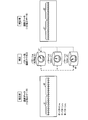
- FIG. 8 is a diagram illustrating an example of the performance estimation model generation process according to the embodiment.
- the performance estimation model generation unit 15 learns the vessel performance by using the aggregated operation data 25 and the actual weather/sea condition data 22 for each vessel maneuvering pattern, and estimates the vessel performance. Generate a model.
- the operation data 25 for each of the marine vessel maneuvering patterns of pattern a, pattern b, and pattern c is collected.
- the performance estimation model generation unit 15 learns ship performance by using, for example, “wind speed” in the actual weather/sea condition data 22 as an explanatory variable and using, for example, “ship speed” in the operation data 25 of the pattern a as an objective variable, The performance estimation model 26 of the pattern a is generated.
- the performance estimation model generation unit 15 learns ship performance by using, for example, “wind speed” in the actual weather/sea condition data 22 as an explanatory variable and using, for example, “ship speed” in the operation data 25 of the pattern b as an objective variable, The performance estimation model 26 of the pattern b is generated.
- the performance estimation model generation unit 15 learns the vessel performance by using, for example, “wind speed” in the actual weather/sea condition data 22 as an explanatory variable and using, for example, “ship speed” in the operation data 25 of the pattern c as an objective variable, The performance estimation model 26 of the pattern c is generated.
- FIG. 9 is a diagram illustrating an image of the performance estimation model generation process according to the embodiment.
- a performance estimation model is generated when the marine vessel maneuvering pattern is the regular output pattern a.
- the only explanatory variable is “wind speed”.
- the performance estimation model generation unit 15 obtains a regression line from two-dimensional coordinates when the x-axis is “wind speed” and the y-axis is “ship speed”.
- the performance estimation model generation unit 15 searches for “ship speed” and “wind speed” at the same time and the same position (latitude, longitude) from the flight data 25 of the pattern a and the actual weather/sea state data 22. Then, the searched “ship speed” and “wind speed” are sampled in two-dimensional coordinates. Then, the performance estimation model generation unit 15 obtains a regression line from the sampled points by the least square method.
- the explanation variable is only the “wind speed”, but it is not limited to this.
- the performance estimation model generation unit 15 sets the x-axis to “wind speed”, the y-axis to “wind direction”, and the z-axis to “ship speed”.
- the objective variable is set to “ship speed”, but the present invention is not limited to this.
- the objective variable may be “fuel consumption”.
- the performance estimating unit 16 estimates the ship performance of the specified marine vessel maneuvering pattern from the forecast weather/sea state data 22 and the performance estimating model 26. For example, the performance estimation unit 16 receives the designation of the marine vessel maneuvering pattern and acquires the performance estimating model 26 corresponding to the marine vessel maneuvering pattern. The performance estimation unit 16 estimates the ship performance at the target position (latitude, longitude) using the acquired performance estimation model 26 and the forecast meteorological/sea state data 22.
- the ship performance referred to here means ship speed and fuel consumption.
- the optimum route searching unit 17 searches for the optimum route for the ship based on the ship performance estimated by the performance estimating unit 16. For example, the optimum route search unit 17 receives the navigation conditions of the ship from the destination that uses the navigation support process. Examples of the destination of use here include a marine vessel and a land-based vessel company that utilize navigation support processing. The navigation conditions of the ship include, for example, a departure place, an arrival place, a departure time, and a marine vessel maneuvering pattern. The optimum route search unit 17 searches the optimum route in the entire section from the departure point to the arrival point when the passenger departs at the designated departure time and selects the designated marine vessel maneuvering pattern.
- the optimum route search unit 17 searches for the optimum route based on the estimated ship performance of each position (latitude, longitude) included in the entire section, and determines the arrival time on the optimum route to the destination. To display.
- the search for the optimum route may be performed by using, for example, the Dijkstra method showing an algorithm for solving the shortest route problem, but any conventional technique may be used as long as the estimated ship performance is used.
- the optimum route search unit 17 also saves the optimum route and arrival time of the designated marine vessel maneuvering pattern in the storage unit 20 as the optimum route search result.
- the optimum route is a route that consumes less fuel and takes less time when operating in each of the selected marine vessel maneuvering patterns.
- the optimum route is a route with less fuel consumption and shorter time when operating in the pattern a.
- the pattern b when the marine vessel maneuvering pattern is medium output
- the pattern c when the marine vessel maneuvering pattern is small output.
- the optimum route search unit 17 searches for the optimum route in the entire section from the departure point to the arrival point, and then corrects the optimum route in a part of the section with another maneuvering pattern according to the instruction from the user.
- the arrival time in consideration of the corrected optimum route may be displayed to the destination.
- the optimum route search unit 17 searches for an optimum route when the designated marine vessel maneuvering pattern is selected in a part of the entire section of the optimum route.
- the optimum route search unit 17 corrects the optimum route of some sections based on the estimated ship performance of each position (latitude, longitude) included in some sections, and optimizes the optimum routes of all sections. Display the arrival time at.
- FIG. 10 is a diagram illustrating an example of the performance estimation process and the optimum route search process according to the embodiment.
- the optimum route search unit 17 receives a departure place, an arrival place, a departure time, and a marine vessel maneuvering pattern, for example, from a ship as navigation conditions of the ship (S100).
- the optimum route search unit 17 inquires about the ship performance (for example, ship speed) when maneuvering in the accepted maneuvering pattern for each position (latitude, longitude) included in the section from the departure place to the arrival place (S110). ..
- the performance estimating unit 16 receives the designation of the marine vessel maneuvering pattern and the target position, and acquires the performance estimating model 26 corresponding to the marine vessel maneuvering pattern.
- the performance estimating unit 16 estimates the ship performance (for example, ship speed) at the target position (latitude, longitude) using the acquired performance estimation model 26 and the forecast weather/sea state data 22.
- the performance estimation part 16 returns the estimated ship performance (for example, ship speed) (S120).
- the performance estimation unit 16 repeatedly estimates the ship performance for all the designated positions of the target and returns the estimated ship performance.
- the optimum route search unit 17 searches for the optimum route of the received marine vessel maneuvering pattern based on the estimated ship performance (for example, ship speed) of each position (latitude, longitude) included in the section, and determines the optimum route.
- the arrival time at is displayed on the ship (S130).
- the optimum route for each marine vessel maneuvering pattern is displayed.
- the optimum route whose marine vessel maneuvering pattern is the pattern a at the regular output is the route indicated by Optimal (normal).
- the optimum route for which the marine vessel maneuvering pattern is pattern b for medium power is the route indicated by Optimal (slow x1).
- the optimum route for which the marine vessel maneuvering pattern is the pattern c at low output is the route indicated by Optimal (slow x2).
- the arrival time when operating in each pattern is displayed.
- the optimum route search unit 17 changes, for example, from a ship to a part of a section and another section when changing a part of the entire section of the optimum route in one of the ship maneuvering patterns to another ship maneuvering pattern.
- a marine vessel maneuvering pattern is accepted (S100).
- the optimum route search unit 17 inquires about the ship performance (for example, ship speed) when maneuvering in another received maneuvering pattern for each position (latitude, longitude) included in a part of the section (S110).
- the performance estimation unit 16 When the performance estimation unit 16 receives the designation of another marine vessel maneuvering pattern and the target position, the performance estimating unit 16 acquires the performance estimation model 26 corresponding to the other marine vessel maneuvering pattern.
- the performance estimating unit 16 estimates the ship performance (for example, ship speed) at the target position (latitude, longitude) using the acquired performance estimation model 26 and the forecast weather/sea state data 22.
- the performance estimation part 16 returns the estimated ship performance (for example, ship speed) (S120).
- the performance estimation unit 16 repeatedly estimates the ship performance for all the designated positions of the target and returns the estimated ship performance.
- the optimum route search unit 17 determines the optimum route of some sections based on the estimated ship performance (eg, ship speed) of each position (latitude, longitude) included in some sections. Correct with the ship handling pattern. Then, the optimum route search unit 17 displays the arrival time on the optimum route of the entire section on the ship in consideration of the corrected optimum route (S130).
- FIG. 11 is a diagram showing an example of the optimum route search result according to the embodiment.
- the upper part of FIG. 11 shows the summary data of the optimum route search results.
- the lower part of FIG. 11 shows detailed data of the optimum route search result.
- FIG. 12 is a diagram showing an operation example of an optimum route search when a section is designated. Note that, in FIG. 12, it is assumed that the user selects the pattern c with the small output instead of the pattern a with the regular output in some sections in order to reduce the fuel consumption amount. The user here is, for example, a captain.
- a screen G0 of options including a plurality of flight patterns is presented.
- the optimum route of the pattern a is actually displayed in the regular output.
- the user selects the option of the pattern c from the option screen G0 in order to change the part c1 of the optimum route of the pattern a to the pattern c with the small output (c2).
- the optimum route search unit 17 can execute the simulation so as to change the designated part of the section c1 to the section c1' when the vessel is operated in the pattern a and the different pattern c.
- FIG. 13 is a diagram showing an example of a simulation of an optimum route search when a section is designated. Note that, in FIG. 13, it is assumed that the user selects the pattern c with the small output instead of the pattern a with the regular output in some sections in order to reduce the fuel consumption amount. The user here is, for example, a captain.
- the optimum route search unit 17 searches the optimum route from the position p0 of the departure place to the position p3 of the arrival place, which is searched by using the performance estimation model of the pattern a, in the pattern a, and Display the arrival time on the route to the destination.
- the departure time at the position p0 is “6:00”.
- the time at the position p1 is “10:00”.
- the time at the position p2 is “14:00” indicated by t2.
- the arrival time at the position p3 is assumed to be "18:00".
- the user selects the option of the pattern c from the option screen G0 for the section c2 from the position p1 to the position p2.
- the optimum route search unit 17 searches for the optimum route of the specified part of the section c2 using the performance estimation model of the pattern c, and determines the arrival time at the optimum route c2′. indicate.
- the time at the position p1 is “10:00”.
- the time at the position p2 is “15:00” indicated by t2′.
- the optimum route search unit 17 displays the changed optimum route and arrival time using the performance estimation model of the pattern c when changing to a pattern c for a part of the section when operating in the pattern a. it can.
- the optimum route search unit 17 searches for the optimum route following the specified partial section using the performance estimation model of the pattern a, and determines the arrival time at the optimum route c3. indicate.
- the time at the position p2 is “15:00” indicated by t2′.
- the arrival time at the position p3 is “19:20” indicated by t3′.
- the optimum route search unit 17 can display the optimum route and the arrival time for the section subsequent to the specified partial section by using the performance estimation model of the pattern a.
- the arrival time is delayed as compared with the case of the pattern a when the user changes a part of the section to the pattern c of the small output instead of the pattern a of the regular output. ..
- FIG. 14 is a diagram illustrating an example of a flowchart of the model learning phase according to the embodiment.
- the operation data classification unit 12 classifies the operation data 21 (step S11), and generates operation data 23 for each weather/sea condition.
- the pattern extraction unit 13 analyzes the pattern of maneuvering from the operation data 23 for each weather/sea condition (step S12). As a result of the analysis, the operation data aggregating unit 14 aggregates operation data for each pattern of marine vessel maneuvering from the operation data 23 for each weather/sea condition (step S13) and stores the operation data 25 for each pattern. Then, the operation data aggregating unit 14 corrects the aggregated operation data for each pattern of marine vessel maneuvering (step S14). Then, the performance estimation model generation unit 15 generates a performance estimation model using the flight data for each pattern (the flight data 25 for each pattern) (step S15). Then, the performance estimation model generation unit 15 stores the generated performance estimation model in the performance estimation model 26.
- FIG. 15 is a diagram illustrating an example of a flowchart of the service providing phase according to the embodiment.
- the optimum route search unit 17 determines whether or not navigation information such as a pattern has been received from the user (step S21). Examples of the destination of use here include a marine vessel and a land-based vessel company that utilize navigation support processing. When it is determined that the navigation information has not been received (step S21; No), the optimum route search unit 17 ends the optimum route search process.
- the performance estimation unit 16 acquires the performance estimation model corresponding to the received pattern (step S22).
- the performance estimating unit 16 estimates the ship performance using the forecast weather/sea state data 22 and the performance estimating model (step S23).
- the optimum route search unit 17 searches for the optimum route for the ship based on the estimated ship performance (step S24).
- the optimum route searching unit 17 displays the searched optimum route for the destination (step S25).
- the optimum route search unit 17 determines whether or not the change of the pattern of a part of all the sections of the optimum route has been received from the user (step S26). When it is determined that the change of the pattern of some sections has been received (step S26; Yes), the optimum route search unit 17 proceeds to step S22. That is, the optimum route search unit 17 proceeds to step S22 in order to perform a route search in a part of the section with the changed pattern and to perform a route search in the section subsequent to the part of the section with the original pattern. To do.
- the optimum route search unit 17 ends the optimum route search process.
- the optimum route search unit 17 upon receiving an instruction from the user, searches for the optimum route according to the instruction and displays the searched optimum route to the user.
- such an optimum route may be used for linking with the automatic pilot control for automatically operating the rudder.
- the autopilot cooperation unit 31 (not shown) on the ship side may cooperate the optimum route searched by the optimum route search unit 17 with the autopilot.
- the autopilot cooperation unit 31 acquires the optimum route search result of the optimum route searched by the optimum route search unit 17.
- the autopilot cooperation unit 31 acquires the current position of the ship using GPS (Global Positioning System).
- the autopilot cooperation unit 31 calculates the azimuth that the ship should travel using the current position of the ship and the optimum route. Then, the autopilot cooperation unit 31 calculates the steering angle indicating the angle between the calculated azimuth and the current azimuth using the calculated azimuth and azimuth sensor. Then, the autopilot cooperation unit 31 gives an instruction to the steering unit of the ship about the calculated steering angle. Thereby, the autopilot cooperation unit 31 can automatically operate the rudder of the ship in cooperation with the autopilot on the optimum route.
- FIG. 16 is a diagram illustrating an example of a flowchart of auto-pilot cooperation processing according to the embodiment. Note that the auto-pilot cooperation processing is performed by the auto-pilot cooperation unit 31 on the ship side, for example. Further, it is assumed that the optimum route displayed by the optimum route search unit 17 is displayed on the ship side.
- the autopilot cooperation unit 31 determines whether or not an instruction for autopilot cooperation has been received (step S31). When it is determined that the instruction for autopilot cooperation has not been received (step S31; No), the autopilot cooperation unit 31 ends the autopilot cooperation processing.
- step S31 when it is determined that the instruction for autopilot cooperation has been accepted (step S31; Yes), the autopilot cooperation unit 31 acquires the optimum route search result of the displayed optimum route (step S32). Then, the autopilot cooperation unit 31 acquires the current position of the ship using GPS, and calculates the azimuth that the ship should travel using the current position of the ship and the optimum route search result (step S33).
- the autopilot cooperation unit 31 performs autopilot using the calculated azimuth and azimuth sensor to calculate the steering angle (step S34). For example, the autopilot cooperation unit 31 acquires the azimuth in which the ship is currently traveling using the azimuth sensor. The autopilot cooperation unit 31 calculates a steering angle indicating an angle between the heading currently in progress and the calculated heading of the vessel.
- the autopilot cooperation unit 31 operates the steering unit using the steering angle (step S35). As a result, the rudder of the ship is operated.
- FIG. 17 is a diagram illustrating a usage example of the navigation support process according to the embodiment.
- the navigation support device 1 is connected to a marine vessel (Sea) using the navigation support processing via a network.
- the navigation support device 1 is connected to an onshore shipping company by a network.
- the navigation support apparatus 1 is connected to various onshore providers via a network.
- Various providers include a weather forecast data provider and an AIS data provider.
- the navigation support device 1 collects actual and forecast meteorological and oceanographic data from a weather forecast data provider.
- the navigation support device 1 collects flight data from a provider of AIS data.
- the collected meteorological and oceanographic data and operational data are reflected in the operational data 21 and the meteorological/oceanographic data (actual results/forecast) 22.
- the captain and land staff inquire of the navigation support device 1 about the optimum route.
- the captain can also inquire of the navigation support device 1 about the optimum route during the voyage.
- the navigation support device 1 When receiving the navigation conditions included in the inquiry, the navigation support device 1 searches for an optimum route in the section from the departure point of the vessel to the arrival point when the departure is made at the departure time and when the designated marine vessel maneuvering pattern is selected. .. Then, the navigation support device 1 returns the searched optimum route to the inquiry source. As a result, the navigation support device 1 can present an accurate optimum route according to the marine vessel maneuvering pattern.
- the navigation support device 1 further corrects a part of the optimum route according to another maneuvering pattern in response to an inquiry about the change of a part of the route, and searches for the corrected optimum route. Then, the navigation support device 1 returns the corrected optimum route to the inquiry source.
- the navigation support apparatus 1 can simulate an optimum route in which a part of the section is replaced with another marine vessel maneuvering pattern.
- the information processing device (PC/smartphone) in the ship may include an autopilot cooperation unit 31.
- the autopilot cooperation unit 31 cooperates with the simulated optimum route and the autopilot. That is, the autopilot cooperation unit 31 calculates the steering angle using the optimum route, the current position of the ship, and the current bearing of the ship, and instructs the steering unit of the ship to operate the rudder of the ship. As a result, the autopilot cooperation unit 31 can automatically operate the rudder of the ship by coordinating the optimum route with the autopilot.
- the navigation support device 1 stores the performance estimation model 26 regarding the speed of the ship for each marine vessel maneuvering pattern.
- the navigation support device 1 accepts a marine vessel maneuvering pattern used in navigation.
- the navigation support device 1 calculates the speed of the ship on the route of the ship based on the performance estimation model corresponding to the received marine vessel maneuvering pattern in the performance estimation model 26 and the meteorological/sea data 22 of the usage.
- the navigation support device 1 displays the arrival time on the optimum route based on the calculated speed of the ship. According to such a configuration, the navigation support device 1 can present an accurate optimum route according to the marine vessel maneuvering pattern by using the performance estimation model 26 of the speed of the vessel (marine vessel performance) for each marine vessel maneuvering pattern.
- the navigation support device 1 uses a part of the optimum route based on the performance estimation model of another marine vessel maneuvering pattern in the performance estimation model 26. Calculate the speed of the ship in the section. The navigation support device 1 corrects the optimum route in the entire section based on the calculated speed of the ship in the section, and displays the arrival time on the corrected optimum route. According to this structure, the navigation support apparatus 1 can execute the simulation of the optimum route when a part of the optimum route is changed to another marine vessel maneuvering pattern. As a result, the navigation support apparatus 1 can present an accurate optimum route according to the marine vessel maneuvering pattern even when a part of the optimum marine route is changed to another marine vessel maneuvering pattern.
- the autopilot cooperation unit 31 calculates the heading of the ship at the current position of the ship from the optimum route.
- the autopilot cooperation unit 31 calculates the steering angle using the azimuth of the ship currently in operation and the azimuth in which the ship should travel.
- the autopilot cooperation unit 31 controls the steering of the ship based on the calculated steering angle. According to such a configuration, the autopilot cooperation unit 31 can automatically operate the rudder of the ship in cooperation with the autopilot in the optimum route.
- the navigation support device 1 classifies the operation data 21 for each weather/sea condition.
- the navigation support device 1 calculates the characteristic distribution of the marine vessel maneuvering for each meteorological and oceanographic condition using the classified navigation data 23.
- the navigation support device 1 extracts a plurality of marine vessel maneuvering patterns from the calculated marine vessel maneuvering characteristic distribution for each weather and ocean condition, and collects operational data for each marine vessel maneuvering pattern.
- the navigation support apparatus 1 generates a learning model for each maneuvering pattern from the operation data aggregated for each maneuvering pattern, using the actual data of weather and ocean conditions as explanatory variables and the ship performance as an objective variable.
- the navigation support device 1 can accurately recommend the optimum route according to the marine vessel maneuvering pattern by using the learning model of the marine vessel performance for each marine vessel maneuvering pattern. For example, the navigation support device 1 can estimate the optimum route that suits the captain's sense by learning the actual maneuvering performed by the captain. As a result, the navigation support device 1 can obtain the economic effect by reducing the fuel cost and the voyage time, and the environmental effect by reducing the carbon dioxide CO 2 .
- the constituent elements of the illustrated navigation support device 1 do not necessarily have to be physically configured as illustrated. That is, the specific mode of the dispersion/integration of the navigation support device 1 is not limited to that shown in the drawings, and all or part of the navigation support device 1 may be functionally or physically arranged in arbitrary units according to various loads and usage conditions. It can be distributed and integrated.
- the operation data classification unit 12 and the pattern extraction unit 13 may be integrated as one unit.
- the operation data aggregating unit 14 is separated into an aggregating unit that aggregates the operation data 23 for each meteorological and oceanographic condition to generate an operation data 25 for each marine vessel maneuvering pattern and a correction unit that corrects the operation data 25 for each marine vessel maneuvering pattern. You may do it.
- the storage unit 20 may be connected as an external device of the navigation support device 1 via a network.
- FIG. 18 is a diagram illustrating an example of a computer that executes a navigation support program.
- the computer 200 includes a CPU 203 that executes various arithmetic processes, an input device 215 that receives data input from a user, and a display control unit 207 that controls the display device 209.
- the computer 200 also includes a drive device 213 that reads a program and the like from a storage medium, and a communication control unit 217 that exchanges data with another computer via a network.
- the computer 200 also has a memory 201 for temporarily storing various information and an HDD (Hard Disk Drive) 205.
- the memory 201, the CPU 203, the HDD 205, the display control unit 207, the drive device 213, the input device 215, and the communication control unit 217 are connected by the bus 219.
- the drive device 213 is, for example, a device for the removable disk 210.
- the HDD 205 stores a navigation support program 205a and navigation support processing related information 205b.
- the CPU 203 reads the navigation support program 205a, expands it in the memory 201, and executes it as a process. Such a process corresponds to each functional unit of the navigation support device 1.
- the navigation support processing related information 205b corresponds to the operation data 21, the weather/sea condition data (actual results/forecast) 22, the operation data (for each weather condition) 23, the pattern 24, the operation data (for each pattern) 25, and the performance estimation model 26. To do.
- the removable disk 210 stores each information such as the navigation support program 205a.
- the navigation support program 205a does not necessarily have to be stored in the HDD 205 from the beginning.
- a "portable physical medium such as a flexible disk (FD), a CD-ROM (Compact Disk Read Only Memory), a DVD (Digital Versatile Disk), a magneto-optical disk, an IC (Integrated Circuit) card, etc., which is inserted into the computer 200.
- the relevant program is stored in.
- the computer 200 may read the navigation support program 205a from these and execute it.
Landscapes
- Engineering & Computer Science (AREA)
- Remote Sensing (AREA)
- Radar, Positioning & Navigation (AREA)
- Physics & Mathematics (AREA)
- General Physics & Mathematics (AREA)
- Automation & Control Theory (AREA)
- Ocean & Marine Engineering (AREA)
- Chemical & Material Sciences (AREA)
- Combustion & Propulsion (AREA)
- Mechanical Engineering (AREA)
- Navigation (AREA)
- Traffic Control Systems (AREA)
Abstract
航海支援装置(1)は、操船パターン毎の船の速度に関する性能推定モデルを記憶し、航海で用いる操船パターンを受け付け、性能推定モデルのうちの、受け付けた操船パターンに対応する性能推定モデルおよび気象海象の予報データに基づいて、航路上での船の速度を算出し、該算出した船の速度に基づいて、最適な航路における到着時刻を表示することで、操船パターンに応じた精度良い最適航路を提示することができる。
Description
本発明は、航海支援方法等に関する。
航海支援技術では、船舶運航データと過去の気象海象データとに基づき船舶の性能を推定し、推定された船舶の性能と、気象海象データとに基づいて、この船舶にとっての最適航路を計算する航海支援システムが知られている(例えば、特許文献1,2参照)。かかる航海支援システムでは、例えば、利用者が、エンジンの回転数を指定すると、システムが予想される気象海象条件での船舶の性能(航行船速や燃料消費量)を推定し、少ない燃料消費量で到着できる最適航路を探索する。
ところで、実際の航海では、船舶の船長は、船舶の設計時に決められた常用出力で、風や波の抵抗の少ない航路を選択する。ここでいう常用出力とは、航海速力を得るために常用する出力で、機関の効率と保守の観点から経済的な出力のことをいう。常用出力で選択される航路が、多くの場合船長の感覚に合った航路であり、燃費が少なく、時間も短い航路とされる。
しかしながら、従来の航海支援システムでは、常用出力での精度良い最適航路を提示することができないという問題がある。すなわち、従来の航海支援システムでは、エンジンの回転数の一定を仮定して最適航路を探索する。この結果、従来の航海支援システムでは、探索された最適航路を通った場合の到着時刻を算出することができる。ところが、実際の航海では、波、風、海流の影響により、エンジンの回転数を一定に保つのは、困難である。仮に一定に保ったとすると、エンジンに負荷がかかり故障に繋がることが知られている。このため、従来の航海支援システムで探索される最適航路や到着時刻は現実と合わないものといえる。したがって、従来の航海支援システムでは、常用出力での精度良い最適航路を提示することができない。
なお、上記課題は、常用出力だけではなく、エンジンに負荷をかけない中出力や燃費を削減するための小出力等の他の操船パターンにも同様に生じる課題である。
本発明は、1つの側面では、操船パターンに応じた精度良い最適航路を提示することを目的とする。
1つの態様では、航海支援方法では、コンピュータが、操船パターン毎の船の速度に関する性能推定モデルを記憶し、航海で用いる操船パターンを受け付け、前記性能推定モデルのうちの、受け付けた操船パターンに対応する性能推定モデルおよび気象海象の予報データに基づいて、前記船の航路上での船の速度を算出し、該算出した船の速度に基づいて、最適な航路における到着時刻を表示する、処理を実行する。
1実施態様によれば、操船パターンに応じた精度良い最適航路を提示することが可能となる。
以下に、本願の開示する航海支援方法、航海支援装置および航海支援プログラムの実施例を図面に基づいて詳細に説明する。なお、本発明は、実施例により限定されるものではない。
[航海支援装置の構成]
図1は、実施例に係る航海支援装置の構成を示す機能ブロック図である。図1に示すように、航海支援装置1は、船舶航海データを気象海象条件毎に分類し、分類した気象海象条件毎に、船速の分布を算出する。航海支援装置1は、分類した気象海象条件毎に算出された操船の分布から抽出される操船パターン毎に船舶運航データを集約する。航海支援装置1は、操船パターン毎に、集約された船舶運航データと、過去の気象海象データとを用いて、船舶性能を学習し、操船パターン毎の船舶性能の推定モデルを構築する。そして、航海支援装置1は、船のスタートからゴールに到るまでの操船パターンを受け付けると、船舶性能の推定モデルのうちの、受け付けた操船パターンに対応する推定モデルに基づいて、スタートからゴールに到るまでの全体の区間での船の速度を算出する。航海支援装置1は、算出した船の速度に基づいて、最適な航路における到着時刻を表示する。
図1は、実施例に係る航海支援装置の構成を示す機能ブロック図である。図1に示すように、航海支援装置1は、船舶航海データを気象海象条件毎に分類し、分類した気象海象条件毎に、船速の分布を算出する。航海支援装置1は、分類した気象海象条件毎に算出された操船の分布から抽出される操船パターン毎に船舶運航データを集約する。航海支援装置1は、操船パターン毎に、集約された船舶運航データと、過去の気象海象データとを用いて、船舶性能を学習し、操船パターン毎の船舶性能の推定モデルを構築する。そして、航海支援装置1は、船のスタートからゴールに到るまでの操船パターンを受け付けると、船舶性能の推定モデルのうちの、受け付けた操船パターンに対応する推定モデルに基づいて、スタートからゴールに到るまでの全体の区間での船の速度を算出する。航海支援装置1は、算出した船の速度に基づいて、最適な航路における到着時刻を表示する。
ここでいう船舶性能には、船舶の航行速度や燃料消費量等が挙げられる。
ここでいう操船パターンとは、実際に、船長が操船する際に選択するパターンのことをいう。操船パターンには、例えば、常用出力で操船される「パターンa」、エンジン出力を少し下げて操船される「パターンb」、減速運航で操船される「パターンc」等が想定される。以降では、操船パターンを単に「パターン」という場合がある。
「パターンa」は、船舶設計時に決められた常用出力で、風や波の抵抗の少ない航路を選択して操船されるパターンである。「常用出力」とは、機関の効率と保守の観点から経済的な出力のことをいう。常用出力で選択される航路が、燃費が少なく、時間も短い航路とされる。パターンaは、常用出力での操船パターンという。
「パターンb」は、荒天の下では、エンジンに負荷をかけない(トルクリッチにならない)ように出力を下げて操船されるパターンである。パターンbは、中出力での操船パターンという。「パターンc」は、次の航海予定がなく、時間に余裕がある場合に、燃費を削減するために減速して操船されるパターンである。パターンcは、小出力での操船パターンという。なお、操船パターンは、これに限定されない。操船パターンには、一例として、時間に余裕がない場合に、エンジンに負荷をかけるように出力を上げて操船されるパターンdを含んでも良い。パターンdは、高出力での操船パターンという。
[航海支援の概要]
ここで、実施例に係る航海支援の概要を、図2を参照して説明する。図2は、実施例に係る航海支援の概要を示す図である。
ここで、実施例に係る航海支援の概要を、図2を参照して説明する。図2は、実施例に係る航海支援の概要を示す図である。
図2に示すように、航海支援装置1は、船舶に係る運航データ21から船速の分布を算出し、船速の分布から操船パターン(パターン)を抽出する(<1>)。船速の分布は、船速の度数分布を示す。ここでは、パターンは、出現頻度に基づいて抽出される。出現頻度が最も高い区間が常用出力のパターンaとして抽出される。船長は、船舶の設計時に決められた常用出力で、風や波の抵抗の少ない航路を選択して航行することが多いからである。出現頻度が次に高い区間が中出力のパターンbとして抽出される。最も船速が遅い区間が小出力のパターンcとして抽出される。なお、分布は、船速の代わりに、エンジン回転数、馬力であっても良い。
そして、航海支援装置1は、パターン毎に、運航データ21´を集約する(<2>)。
そして、航海支援装置1は、パターン毎に、集約された運航データ21´と、実績の気象・海象データ(実績・予報)22とを用いて、船舶性能を学習し、パターン毎の船舶性能の推定モデルを構築する(<3>)。
そして、航海支援装置1は、例えば船舶から船舶のスタート地点、スタート時刻およびゴール地点を受け付けると、予報の気象・海象データ(実績・予報)22と、パターン毎の船舶性能の推定モデルとから、船舶のスタートからゴールに到るまで、パターン毎に、船舶性能を推定する。ここでいう船舶性能は、船舶の航行速度や燃料消費量等を示す。そして、航海支援装置1は、パターン毎に、推定された船舶性能に基づいて、船舶にとっての最適航路を算出し、最適航路における到着時刻を受け付け元の例えば船舶に対して表示する(<4>)。
図1に戻って、航海支援装置1は、制御部10および記憶部20を有する。
制御部10は、CPU(Central Processing Unit)等の電子回路に対応する。そして、制御部10は、各種の処理手順を規定したプログラムや制御データを格納するための内部メモリを有し、これらによって種々の処理を実行する。制御部10は、データ収集部11、運航データ分類部12、パターン抽出部13、運航データ集約部14および性能推定モデル生成部15を有する。また、制御部10は、性能推定部16および最適航路探索部17を有する。なお、運航データ分類部12、パターン抽出部13、運航データ集約部14および性能推定モデル生成部15は、モデル学習フェーズの機能部である。また、性能推定部16および最適航路探索部17は、サービス提供フェーズの機能部である。なお、性能推定部16および最適航路探索部17は、算出部の一例である。最適航路探索部17は、表示部の一例である。
記憶部20は、例えば、RAM、フラッシュメモリ(Flash Memory)等の半導体メモリ素子、または、ハードディスク、光ディスク等の記憶装置である。記憶部20は、運航データ21、気象・海象データ(実績・予報)22、運航データ(気象海象条件毎)23、パターン24、運航データ(パターン毎)25および性能推定モデル26を有する。なお、性能推定モデル26は、記憶部の一例である。
運航データ21は、船舶が運航時に、いつ、どこで、どのくらいの速度で、どちらの方向に向かっていたのか等を示すデータである。言い換えれば、運航データ21は、船舶の船長が行った操船の履歴を示すデータである。運航データ21は、例えば、AIS(Automatic Identification System)やVDR(Voyage Data Recorder)、エンジンロガーを利用して収集される。
ここで、運航データ21の一例を、図3を参照して説明する。図3は、実施例に係る運航データの一例を示す図である。図3に示すように、運航データ21は、versel_name毎に、緯度、経度、速度、進行方向、・・・、船首方向、時刻、・・・、を対応付けて記憶する。versel_nameは、船舶の名称を示す。なお、運航データ21は、これに限定されず、さらに、エンジン回転数、消費燃料を加えても良い。
図1に戻って、気象・海象データ(実績・予報)22は、船舶の実績および予報を含む気象データおよび海象データである。気象・海象データ(実績・予報)22は、例えば、天気予報データのプロバイダから配信されたデータを利用して収集されれば良い。
ここで、気象・海象データ(実績・予報)22の一例を、図4を参照して説明する。図4は、実施例に係る気象・海象データの一例を示す図である。図4上図には、気象データのうち予報の風データが表わされている。図4中図には、海象データのうち予報の波データが表わされている。図4下図には、海象データのうち予報の海流データが表わされている。
図4上図に示すように、風データは、緯度、経度、風速および風向を、予報配信日時おおび対象日時に対応付けて記憶する。図4中図に示すように、波データは、緯度、経度、波高、波向、波周期を、予報配信日時および対象日時に対応付けて記憶する。図4下図に示すように、海流データは、緯度、経度、海流速度、海流方向、階層を、予報配信日時および対象日時に対応付けて記憶する。
図1に戻って、運航データ(気象海象条件毎)23は、運航データ21のうち気象海象条件毎に分類された運航データである。なお、運航データ(気象海象条件毎)23は、運航データ分類部12によって分類される。
パターン24は、複数の操船パターンのうち抽出された操船パターンである。なお、パターン24は、パターン抽出部12によって抽出される。
運航データ(パターン毎)25は、運航データ21のうちパターン毎に集約された運航データである。なお、運航データ(パターン毎)25は、運航データ集約部14によって集約される。
性能推定モデル26は、パターン毎の船舶性能の推定モデルである。なお、性能推定モデル26は、性能推定モデル生成部15によって生成される。
データ収集部11は、各種データを収集する。例えば、データ収集部11は、AISを利用して運航データ21を収集する。データ収集部11は、天気予報データのプロバイダから配信される気象データ(実績・予報)および海象データ(実績・予報)を受信して、気象・海象データ(実績・予報)22を収集する。
運航データ分類部12は、運航データ21を気象海象条件毎に分類する。
ここで、運航データ分類の一例を、図5を参照して説明する。図5は、実施例に係る運航データ分類処理の一例を示す図である。図5に示すように、運航データ分類部12は、運航データ21を、あらかじめ定められた気象海象条件毎に分類して、気象海象条件毎の運航データ23を生成する。ここでは、気象海象条件として、風速および風向を適用した場合である。気象海象条件の一例として、風力「0」である場合、風力「1」および前方である場合、風力「1」および後方である場合、・・・、風力「10」および左舷後方である場合が示されている。かかる気象海象条件毎に、運航データ21は、気象海象条件毎の運航データ23に分類される。
パターン抽出部13は、気象海象条件毎の運航データ23の船速データをクラスタリングして、操船パターン(パターン)を抽出する。例えば、パターン抽出部13は、気象海象条件毎の運航データ23の少なくとも運航時の位置(緯度、経度)、時刻、船速を含むデータを利用して、船速データをクラスタリングする。クラスタリングには、一例として、k-means法等を用いれば良い。そして、パターン抽出部13は、クラスタリングの結果、一例として、常用出力での操船パターン(パターンa)、中出力での操船パターン(パターンb)、小出力での操船パターン(パターンc)等を抽出する。そして、パターン抽出部13は、抽出したパターンをパターン24に保存する。なお、パターン抽出部13は、気象海象条件毎の運航データ23の船速データをクラスタリングして、パターンを抽出すると説明したが、これに限定されず、船速データの代わりにエンジン回転数、馬力を用いてクラスタリングして、パターンを抽出しても良い。
図1に戻って、運航データ集約部14は、気象海象条件毎の運航データ23を用いて、船速の分布を算出する。ここでいう船速の分布とは、例えば、船速の出現頻度分布のことをいう。すなわち、運航データ集約部14は、気象海象条件毎の運航データ23について、船速の出現頻度分布を算出する。
また、運航データ集約部14は、気象海象条件毎に算出された船速の分布の出現頻度に基づいて、分布の区間を分割する。分割される区間は、操船パターンに対応付けられる。これにより、運航データ集約部14は、同一の気象海象条件において、船速の出現頻度を算出することで、出現頻度が最も高い船速の区間を常用出力の操船パターンとみなすことができる。つまり、船長が船舶を操船するときには、経済的な出力である常用出力を選択することが多いと想定されるからである。同様に、運航データ集約部14は、同一の気象海象条件において、船速の出現頻度を算出することで、出現頻度と船速とから得られる分布の区間を所定の操船パターンとみなすことができる。
また、運航データ集約部14は、操船パターン毎に、気象海象条件毎の運航データ23を集約して、操船パターン毎の運航データ25を生成する。
なお、運航データ集約部14は、操船パターン毎の運航データ25を集約する際、操船パターン毎の運航データ25を補正しても良い。すなわち、運航データ集約部14は、同一の気象海象条件について、船速の出現頻度に基づいて、操船パターンを決定する。ところが、運航データ集約部14は、船速だけで操船パターンを決定すると、非常に短期間で操船パターンを切り替えるように集約されてしまうが、現実には、非常に短期間で操船パターンを切り替えることはない。したがって、運航データ集約部14は、操船パターンの継続期間が所定期間以内の場合には、所定期間に含まれる最多の操船パターンをその期間の操船パターンとして操船パターンの運航データを補正するのが望ましい。
ここで、運航データ集約の一例を、図6を参照して説明する。図6は、実施例に係る運航データ集約処理の一例を示す図である。図6では、運航データ集約部14が、常用出力の操船パターンについて、気象海象条件毎の運航データ23を集約して、常用出力の操船パターンの運航データ25を生成する場合を説明する。
運航データ集約部14は、気象海象条件毎の運航データ23を用いて、それぞれの船速の度数分布表を算出する。
そして、運航データ集約部14は、算出された船速の度数分布表の出現頻度に基づいて、分布の区間を分割する。ここでは、最も出現頻度が高い船速の区間が、常用出力の操船パターンとみなされる。これは、船長が船舶を操船するとき、経済的な出力である常用出力を選択することが多いと想定されるからである。
そして、運航データ集約部14は、気象海象条件毎の運航データ23を集約して、常用出力の操船パターンの運航データ25を生成する。ここでは、最も出現頻度が高い船速の区間が、常用出力の操船パターンとみなされる。したがって、運航データ集約部14は、気象海象条件毎に算出されたそれぞれの度数分布表のうち、最も出現頻度が高い船速の区間の運航データを集約して、常用出力の操船パターンの運航データ25を生成する。
なお、出現頻度が次に高い船速の区間が、中出力の操船パターンとしても良い。かかる場合には、運航データ集約部14は、気象海象条件毎に算出されたそれぞれの度数分布表のうち、出現頻度が次に高い船速の分布の区間の運航データを集約して、中出力の操船パターンの運航データ25を生成する。また、最も船速が遅い分布の区間が、小出力の操船パターンとしても良い。かかる場合には、運航データ集約部14は、気象海象条件毎に算出されたそれぞれの度数分布表のうち、最も船速が遅い分布の区間の運航データを集約して、小出力の操船パターンの運航データ25を生成する。また、最も船速が速い分布の区間が、高出力の操船パターンとしても良い。かかる場合には、運航データ集約部14は、気象海象条件毎に算出されたそれぞれの度数分布表のうち、最も船速が速い分布の区間の運航データを集約して、高出力の操船パターンの運航データ25を生成する。
図7は、実施例に係るパターン毎運航データの補正処理の一例を示す図である。図7では、運航データ集約部14は、パターンa(常用出力)、パターンb、パターンcのように、操船パターン毎の運航データ25を集約したものとする。
図7に示すように、補正前の1分毎の運航データが表わされている。それぞれの運航データは、船速の出現頻度に基づいて、操船パターンを切り替えている。ところが、運航データ集約部14は、船速だけで操船パターンを決定すると、非常に短期間で操船パターンを切り替えることになるが、現実には、非常に短期間で操船パターンを切り替えることはない。したがって、運航データ集約部14は、操船パターンの継続時間が所定期間以内の場合には、所定期間に含まれる最多の操船パターンをその期間の操船パターンとして操船パターンの運航データを補正する。ここでは、符号d1で示されるそれぞれの運航データは、パターンaが最多であるので、符号d1´で示されるように、最多のパターンaの運航データとして補正される。すなわち、運航データ集約部14は、パターンcの運航データおよびパターンbの運航データをパターンaの運航データとして補正する。また、符号d2で示されるそれぞれの運航データは、パターンcが最多であるので、符号d2´で示されるように、最多のパターンcの運航データとして補正される。すなわち、運航データ集約部14は、パターンaの運航データおよびパターンbの運航データをパターンcの運航データとして補正する。これにより、運航データ集約部14は、現実に即して、操船パターン毎の運航データを集約することができる。
図1に戻って、性能推定モデル生成部15は、操船パターン毎に、集約された運航データ25と、実績の気象・海象データ22とを用いて、船舶性能を学習し、船舶性能の推定モデルを生成する。例えば、性能推定モデル生成部15は、実績の気象・海象データ22を説明変数として、操船パターン毎に集約された運航データ25の船舶性能を目的変数として、操船パターン毎の性能推定モデル26を生成する。一例として、性能推定モデル生成部15は、以下の式(1)の重回帰式を最小二乗法により操船パターン毎の性能推定モデル26を生成する。なお、式(1)のyは、目的変数であり、例えば、船速を示す。式(1)のx1~x6は、それぞれ説明変数であり、例えば、風速、風向、波高、波向、海流速度、海流方向を示す。
y=β0+β1x1+β2x2+β3x3+β4x4+β5x5+β6x6・・・式(1)
y=β0+β1x1+β2x2+β3x3+β4x4+β5x5+β6x6・・・式(1)
ここで、実施例に係る性能推定モデル生成の一例を、図8を参照して説明する。図8は、実施例に係る性能推定モデル生成処理の一例を示す図である。図8に示すように、性能推定モデル生成部15は、操船パターン毎に、集約された運航データ25と、実績の気象・海象データ22とを用いて、船舶性能を学習し、船舶性能の推定モデルを生成する。ここでは、パターンa、パターンbおよびパターンcの操船パターン毎の運航データ25が集約されている。性能推定モデル生成部15は、実績の気象・海象データ22のうち例えば「風速」を説明変数として、パターンaの運航データ25のうち例えば「船速」を目的変数として、船舶性能を学習し、パターンaの性能推定モデル26を生成する。性能推定モデル生成部15は、実績の気象・海象データ22のうち例えば「風速」を説明変数として、パターンbの運航データ25のうち例えば「船速」を目的変数として、船舶性能を学習し、パターンbの性能推定モデル26を生成する。性能推定モデル生成部15は、実績の気象・海象データ22のうち例えば「風速」を説明変数として、パターンcの運航データ25のうち例えば「船速」を目的変数として、船舶性能を学習し、パターンcの性能推定モデル26を生成する。
ここで、実施例に係る性能推定モデル生成処理のイメージを、図9を参照して説明する。図9は、実施例に係る性能推定モデル生成処理のイメージを示す図である。なお、図9では、操船パターンが常用出力のパターンaである場合の性能推定モデルを生成する場合を説明する。説明の便宜上、説明変数を「風速」のみとする。
図9に示すように、性能推定モデル生成部15は、x軸を「風速」とし、y軸を「船速」とした場合の2次元座標から、回帰直線を求める。ここでは、性能推定モデル生成部15は、パターンaの運航データ25と、実績の気象・海象データ22とから、同一時刻および同一位置(緯度、経度)の「船速」および「風速」を探索し、探索した「船速」および「風速」を2次元座標にサンプリングする。そして、性能推定モデル生成部15は、サンプリングした複数の点を最小二乗法により、回帰直線を求める。
すなわち、性能推定モデル生成部15は、式(2)を最小にするパラメータβ0、β1を求めて、回帰直線y=β0+β1x1を求める。

なお、図9では、説明の便宜上、説明変数を「風速」のみとしたが、これに限定されない。例えば、説明変数を「風速」、「風向」とした場合には、性能推定モデル生成部15は、x軸を「風速」とし、y軸を「風向」とし、z軸を「船速」とした場合の3次元座標から、回帰直線y=β0+β1x1+β2x2を求めれば良い。また、図9では、目的変数を「船速」としたが、これに限定されない。例えば、目的変数を「燃料消費」としても良い。
図1に戻って、性能推定部16は、予報の気象・海象データ22と、性能推定モデル26とから、指定された操船パターンの船舶性能を推定する。例えば、性能推定部16は、操船パターンの指定を受け付けると、操船パターンに対応する性能推定モデル26を取得する。性能推定部16は、取得した性能推定モデル26および予報の気象・海象データ22を用いて、対象の位置(緯度、経度)の船舶性能を推定する。ここでいう船舶性能とは、船速や燃料消費のことをいう。
最適航路探索部17は、性能推定部16によって推定される船舶性能に基づき、船舶にとっての最適航路を探索する。例えば、最適航路探索部17は、航海支援処理を利用する利用先から船舶の航海条件を受け付ける。ここでいう利用先とは、一例として、航海支援処理を利用する海上の船舶や陸上の船舶会社が挙げられる。船舶の航海条件には、一例として、出発地、到着地、出発時刻、操船パターンが挙げられる。最適航路探索部17は、出発地から到着地までの全体の区間において、指定された出発時刻で出発した場合且つ指定された操船パターンを選択した場合の最適航路を探索する。一例として、最適航路探索部17は、全体の区間に含まれるそれぞれの位置(緯度、経度)の推定される船舶性能に基づいて、最適航路を探索し、最適航路における到着時刻を利用先に対して表示する。最適航路の探索は、一例として、最短経路問題を解くためのアルゴリズムを示すダイクストラ法を用いれば良いが、推定される船舶性能を用いれば、いかなる従来技術を用いても構わない。
また、最適航路探索部17は、指定された操船パターンの最適航路および到着時刻を最適航路探索結果として記憶部20に保存する。
なお、最適航路とは、選択されるそれぞれの操船パターンでの運行において、燃料消費が少なく、時間も短い航路となる。例えば、操船パターンが常用出力でのパターンaである場合には、最適航路とは、パターンaで運航した場合での、燃料消費が少なく、時間も短い航路となる。操船パターンが中出力でのパターンb、操船パターンが小出力でのパターンcにおいても同様である。
また、最適航路探索部17は、出発地から到着地までの全体の区間における最適航路を探索した後、利用先からの指示に応じて、一部区間の最適航路を別の操船パターンで修正し、修正した最適航路を考慮した到着時刻を利用先に対して表示しても良い。かかる場合には、最適航路探索部17は、最適航路の全体の区間のうち一部区間において、指定された操船パターンを選択した場合の最適航路を探索する。一例として、最適航路探索部17は、一部区間に含まれるそれぞれの位置(緯度、経度)の推定される船舶性能に基づいて、一部区間の最適航路を修正し、全体の区間の最適航路における到着時刻を表示すれば良い。
[性能推定処理および最適航路探索処理の一例]
図10は、実施例に係る性能推定処理および最適航路探索処理の一例を示す図である。図10に示すように、最適航路探索部17は、例えば船舶から、船舶の航海条件として出発地、到着地、出発時刻、操船パターンを受け付ける(S100)。最適航路探索部17は、出発地から到着地までの区間に含まれるそれぞれの位置(緯度、経度)について、受け付けた操船パターンで操船した場合の船舶性能(例えば、船速)を問い合わせる(S110)。
図10は、実施例に係る性能推定処理および最適航路探索処理の一例を示す図である。図10に示すように、最適航路探索部17は、例えば船舶から、船舶の航海条件として出発地、到着地、出発時刻、操船パターンを受け付ける(S100)。最適航路探索部17は、出発地から到着地までの区間に含まれるそれぞれの位置(緯度、経度)について、受け付けた操船パターンで操船した場合の船舶性能(例えば、船速)を問い合わせる(S110)。
性能推定部16は、操船パターンおよび対象の位置の指定を受け付けると、操船パターンに対応する性能推定モデル26を取得する。性能推定部16は、取得した性能推定モデル26および予報の気象・海象データ22を用いて、対象の位置(緯度、経度)の船舶性能(例えば、船速)を推定する。そして、性能推定部16は、推定した船舶性能(例えば、船速)を返却する(S120)。性能推定部16は、対象の指定された全ての位置について、繰り返し船舶性能を推定して、推定した船舶性能を返却する。
そして、最適航路探索部17は、区間に含まれるそれぞれの位置(緯度、経度)の推定される船舶性能(例えば、船速)に基づいて、受け付けた操船パターンの最適航路を探索し、最適航路における到着時刻を、船舶に対して表示する(S130)。ここでは、船舶側では、操船パターン毎の最適航路が表示されている。操船パターンが常用出力でのパターンaである最適航路は、Optimal(normal)で示される航路である。操船パターンが中出力でのパターンbである最適航路は、Optimal(slow x1)で示される航路である。操船パターンが小出力でのパターンcである最適航路は、Optimal(slow x2)で示される航路である。そして、それぞれのパターンで運航した場合の到着時刻が表示される。
さらに、最適航路探索部17は、いずれかの操船パターンでの最適航路の全体の区間のうち一部の区間を別の操船パターンに変更する場合に、例えば船舶から、一部の区間および別の操船パターンを受け付ける(S100)。最適航路探索部17は、一部の区間に含まれるそれぞれの位置(緯度、経度)について、受け付けた別の操船パターンで操船した場合の船舶性能(例えば、船速)を問い合わせる(S110)。
性能推定部16は、別の操船パターンおよび対象の位置の指定を受け付けると、別の操船パターンに対応する性能推定モデル26を取得する。性能推定部16は、取得した性能推定モデル26および予報の気象・海象データ22を用いて、対象の位置(緯度、経度)の船舶性能(例えば、船速)を推定する。そして、性能推定部16は、推定した船舶性能(例えば、船速)を返却する(S120)。性能推定部16は、対象の指定された全ての位置について、繰り返し船舶性能を推定して、推定した船舶性能を返却する。
そして、最適航路探索部17は、一部の区間に含まれるそれぞれの位置(緯度、経度)の推定される船舶性能(例えば、船速)に基づいて、一部の区間の最適航路を別の操船パターンで修正する。そして、最適航路探索部17は、修正した最適航路を考慮したうえで、全体の区間の最適航路における到着時刻を、船舶に対して表示する(S130)。
図11は、実施例に係る最適航路探索結果の一例を示す図である。図11上図には、最適航路探索結果のサマリデータが示されている。図11下図には、最適航路探索結果の詳細データが示されている。
[区間指定の場合の最適航路探索の操作例]
ここで、第1のパターンで航路の全体を運航した場合の最適航路に対して、一部の区間を第2のパターンに変更する場合の最適航路探索の操作例を、図12を参照して説明する。図12は、区間指定の場合の最適航路探索の操作例を示す図である。なお、図12では、利用者が、燃料消費量を減らすために、一部の区間を常用出力でのパターンaの代わりに小出力でのパターンcを選択する場合であるとする。ここでいう利用者は、例えば船長である。
ここで、第1のパターンで航路の全体を運航した場合の最適航路に対して、一部の区間を第2のパターンに変更する場合の最適航路探索の操作例を、図12を参照して説明する。図12は、区間指定の場合の最適航路探索の操作例を示す図である。なお、図12では、利用者が、燃料消費量を減らすために、一部の区間を常用出力でのパターンaの代わりに小出力でのパターンcを選択する場合であるとする。ここでいう利用者は、例えば船長である。
図12に示すように、利用者が最適航路の一部の区間c1を指定すると、複数の運航パターンを含む選択肢の画面G0が提示される。ここでは、現に常用出力でのパターンaの最適航路が表示されているとする。利用者は、パターンaの最適航路の一部の区間c1を小出力でのパターンcに変更するべく、選択肢の画面G0からパターンcの選択肢を選択する(c2)。すると、最適航路探索部17は、指定された一部の区間c1をパターンaと別のパターンcで操船した場合の区間c1´に変更すべく、シミュレーションを実行することができる。
[区間指定の場合の最適航路探索の一例]
ここで、第1のパターンで航路の全体を運航した場合の最適航路に対して、一部の区間を第2のパターンに変更する場合の最適航路探索のシミュレーションの一例を、図13を参照して説明する。図13は、区間指定の場合の最適航路探索のシミュレーションの一例を示す図である。なお、図13では、利用者が、燃料消費量を減らすために、一部の区間を常用出力でのパターンaの代わりに小出力でのパターンcを選択する場合であるとする。ここでいう利用者は、例えば船長である。
ここで、第1のパターンで航路の全体を運航した場合の最適航路に対して、一部の区間を第2のパターンに変更する場合の最適航路探索のシミュレーションの一例を、図13を参照して説明する。図13は、区間指定の場合の最適航路探索のシミュレーションの一例を示す図である。なお、図13では、利用者が、燃料消費量を減らすために、一部の区間を常用出力でのパターンaの代わりに小出力でのパターンcを選択する場合であるとする。ここでいう利用者は、例えば船長である。
図13上段に示すように、最適航路探索部17は、パターンaの性能推定モデルを用いて探索された出発地の位置p0から到着地の位置p3までの最適航路をパターンaで探索し、最適航路における到着時刻を利用先に対して表示する。ここでは、位置p0の出発時刻は「6:00」であるとする。位置p1の時刻は「10:00」であるとする。位置p2の時刻はt2が示す「14:00」であるとする。そして、位置p3の到着時刻は「18:00」であるとする。
ここで、利用者が位置p1から位置p2までの区間c2について、選択肢の画面G0からパターンcの選択肢を選択する。
すると、図13中段に示すように、最適航路探索部17は、指定された一部の区間c2の最適航路を、パターンcの性能推定モデルを用いて探索し、最適航路c2´における到着時刻を表示する。ここでは、位置p1の時刻は「10:00」であるとする。位置p2の時刻はt2´が示す「15:00」であるとする。このようにして、最適航路探索部17は、パターンaで運航した場合の一部の区間についてパターンcに変更する場合に、パターンcの性能推定モデルを用いて変更した最適航路および到着時刻を表示できる。
そして、図13下段に示すように、最適航路探索部17は、指定された一部の区間に後続する最適航路を、パターンaの性能推定モデルを用いて探索し、最適航路c3における到着時刻を表示する。ここでは、位置p2の時刻はt2´が示す「15:00」であるとする。位置p3の到着時刻はt3´が示す「19:20」であるとする。このようにして、最適航路探索部17は、指定された一部の区間に後続する区間について、パターンaの性能推定モデルを用いて最適航路および到着時刻を表示できる。かかる場合には、利用者が一部の区間を常用出力でのパターンaの代わりに、小出力でのパターンcに変更することで、パターンaの場合と比べて到着時刻が遅延することがわかる。
[モデル学習フェーズのフローチャート]
図14は、実施例に係るモデル学習フェーズのフローチャートの一例を示す図である。
図14は、実施例に係るモデル学習フェーズのフローチャートの一例を示す図である。
図14に示すように、運航データ分類部12は、運航データ21を分類して(ステップS11)、気象海象条件毎の運航データ23を生成する。
パターン抽出部13は、気象海象条件毎の運航データ23から、操船のパターンを分析する(ステップS12)。運航データ集約部14は、分析した結果、気象海象条件毎の運航データ23から、操船のパターン別運航データを集約して(ステップS13)、パターン毎の運航データ25を保存する。そして、運航データ集約部14は、集約された操船のパターン別運航データを補正する(ステップS14)。そして、性能推定モデル生成部15は、パターン別運航データ(パターン毎の運航データ25)を用いて、性能推定モデルを生成する(ステップS15)。そして、性能推定モデル生成部15は、生成した性能推定モデルを性能推定モデル26に保存する。
[サービス提供フェーズのフローチャート]
図15は、実施例に係るサービス提供フェーズのフローチャートの一例を示す図である。
図15は、実施例に係るサービス提供フェーズのフローチャートの一例を示す図である。
図15に示すように、最適航路探索部17は、利用先からパターン等の航海情報を受け付けたか否かを判定する(ステップS21)。ここでいう利用先とは、一例として、航海支援処理を利用する海上の船舶や陸上の船舶会社が挙げられる。航海情報を受け付けていないと判定した場合には(ステップS21;No)、最適航路探索部17は、最適航路探索処理を終了する。
一方、航海情報を受け付けたと判定した場合には(ステップS21;Yes)、性能推定部16は、受け付けたパターンに対応する性能推定モデルを取得する(ステップS22)。性能推定部16は、予報の気象・海象データ22および性能推定モデルを用いて、船舶性能を推定する(ステップS23)。そして、最適航路探索部17は、推定された船舶性能に基づき、船舶にとっての最適航路を探索する(ステップS24)。そして、最適航路探索部17は、利用先に対して、探索された最適航路を表示する(ステップS25)。
そして、最適航路探索部17は、利用先から、最適航路の全ての区間のうち一部の区間のパターンの変更を受け付けたか否かを判定する(ステップS26)。一部の区間のパターンの変更を受け付けたと判定した場合には(ステップS26;Yes)、最適航路探索部17は、ステップS22に移行する。すなわち、最適航路探索部17は、一部の区間を変更されたパターンで航路探索を行うべく、且つ、一部の区間に後続する区間を元のパターンで航路探索を行うべく、ステップS22に移行する。
一方、一部の区間のパターンの変更を受け付けていないと判定した場合には(ステップS26;No)、最適航路探索部17は、最適航路探索処理を終了する。
[オートパイロット連携]
なお、最適航路探索部17は、利用先からの指示を受け付けると、指示に応じた最適航路を探索し、探索された最適航路を利用先に対して表示すると説明した。利用先では、かかる最適航路を、舵の操作を自動的に行うオートパイロット制御と連携させるために利用しても良い。例えば、船舶側のオートパイロット連携部31(図示せず)が、最適航路探索部17によって探索された最適航路とオートパイロットを連携すれば良い。例えば、オートパイロット連携部31は、最適航路探索部17によって探索された最適航路の最適航路探索結果を取得する。オートパイロット連携部31は、GPS(Global Positioning System)を用いて船舶の現在の位置を取得する。そして、オートパイロット連携部31は、船舶の現在の位置および最適航路を用いて、船舶が進むべき方位を算出する。そして、オートパイロット連携部31は、算出された方位および方位センサを用いて、算出された方位と現在の方位との角度を示す操舵角を算出する。そして、オートパイロット連携部31は、算出された操舵角を船舶の操舵部に対して指示する。これにより、オートパイロット連携部31は、最適航路をオートパイロットと連携して、自動的に船舶の舵を操作することができる。
なお、最適航路探索部17は、利用先からの指示を受け付けると、指示に応じた最適航路を探索し、探索された最適航路を利用先に対して表示すると説明した。利用先では、かかる最適航路を、舵の操作を自動的に行うオートパイロット制御と連携させるために利用しても良い。例えば、船舶側のオートパイロット連携部31(図示せず)が、最適航路探索部17によって探索された最適航路とオートパイロットを連携すれば良い。例えば、オートパイロット連携部31は、最適航路探索部17によって探索された最適航路の最適航路探索結果を取得する。オートパイロット連携部31は、GPS(Global Positioning System)を用いて船舶の現在の位置を取得する。そして、オートパイロット連携部31は、船舶の現在の位置および最適航路を用いて、船舶が進むべき方位を算出する。そして、オートパイロット連携部31は、算出された方位および方位センサを用いて、算出された方位と現在の方位との角度を示す操舵角を算出する。そして、オートパイロット連携部31は、算出された操舵角を船舶の操舵部に対して指示する。これにより、オートパイロット連携部31は、最適航路をオートパイロットと連携して、自動的に船舶の舵を操作することができる。
[オートパイロット連携処理のフローチャート]
図16は、実施例に係るオートパイロット連携処理のフローチャートの一例を示す図である。なお、オートパイロット連携処理は、例えば船舶側のオートパイロット連携部31が行うものとする。また、船舶側では、最適航路探索部17によって表示された最適航路が表わされているとする。
図16は、実施例に係るオートパイロット連携処理のフローチャートの一例を示す図である。なお、オートパイロット連携処理は、例えば船舶側のオートパイロット連携部31が行うものとする。また、船舶側では、最適航路探索部17によって表示された最適航路が表わされているとする。
図16に示すように、オートパイロット連携部31は、オートパイロット連携の指示を受け付けたか否かを判定する(ステップS31)。オートパイロット連携の指示を受け付けていないと判定した場合には(ステップS31;No)、オートパイロット連携部31は、オートパイロット連携処理を終了する。
一方、オートパイロット連携の指示を受け付けたと判定した場合には(ステップS31;Yes)、オートパイロット連携部31は、表示された最適航路の最適航路探索結果を取得する(ステップS32)。そして、オートパイロット連携部31は、GPSを用いて船舶の現在の位置を取得し、船舶の現在の位置および最適航路探索結果を用いて、船舶の進むべき方位を算出する(ステップS33)。
そして、オートパイロット連携部31は、算出された方位および方位センサを用いて、オートパイロットを行い、操舵角を算出する(ステップS34)。例えば、オートパイロット連携部31は、方位センサを用いて船舶が現在進んでいる方位を取得する。オートパイロット連携部31は、現在進んでいる方位と、算出された船舶の進むべき方位との角度を示す操舵角を算出する。
そして、オートパイロット連携部31は、操舵角を用いて、操舵部を操作する(ステップS35)。この結果、船舶の舵が操作される。
[航海支援処理の利用例]
図17は、実施例に係る航海支援処理の利用例を示す図である。図17に示すように、航海支援装置1が、航海支援処理を利用する海上(Sea)の船舶とネットワークで接続される。航海支援装置1は、陸上(on shore)の船舶会社(Shipping company)とネットワークで接続される。また、航海支援装置1は、陸上(on shore)の各種プロバイダとネットワークで接続される。各種プロバイダには、天気予報データのプロバイダ(Weather forecast data provider)やAISデータのプロバイダ(AIS data provider)が含まれる。
図17は、実施例に係る航海支援処理の利用例を示す図である。図17に示すように、航海支援装置1が、航海支援処理を利用する海上(Sea)の船舶とネットワークで接続される。航海支援装置1は、陸上(on shore)の船舶会社(Shipping company)とネットワークで接続される。また、航海支援装置1は、陸上(on shore)の各種プロバイダとネットワークで接続される。各種プロバイダには、天気予報データのプロバイダ(Weather forecast data provider)やAISデータのプロバイダ(AIS data provider)が含まれる。
航海支援装置1では、天気予報データのプロバイダから実績および予報の気象海象データを収集する。航海支援装置1は、AISデータのプロバイダから運航データを収集する。収集した気象海象データおよび運航データは、運航データ21および気象・海象データ(実績・予報)22に反映される。
船長や陸上職員は、航海前に、最適航路を航海支援装置1に問い合わせる。また、船長は、航海中に、最適航路を航海支援装置1に問い合わせることもできる。
航海支援装置1は、問い合わせに含まれる航海条件を受け付けると、船舶の出発地から到着地までの区間において、出発時刻で出発した場合且つ指定された操船パターンを選択した場合の最適航路を探索する。そして、航海支援装置1は、探索した最適航路を問い合わせ元へ返す。これにより、航海支援装置1は、操船パターンに応じた精度良い最適航路を提示することができる。
また、航海支援装置1は、最適航路を探索した後、さらに一部区間の変更の問い合わせに応じて、最適航路の一部区間を別の操船パターンで修正し、修正した最適航路を探索する。そして、航海支援装置1は、修正した最適航路を問い合わせ元へ返す。これにより、航海支援装置1は、一部区間を別の操船パターンに代えた最適航路をシミュレーションすることができる。
また、船舶内の情報処理装置(PC/smartphone)は、オートパイロット連携部31を備えていても良い。オートパイロット連携部31は、シミュ―レーションされた最適航路と、オートパイロットとを連携する。すなわち、オートパイロット連携部31は、最適航路並びに、現在の船舶の位置および現在の船舶の方位を用いて、操舵角を算出して、船舶の操舵部に指示し、船舶の舵を操作する。これにより、オートパイロット連携部31は、最適航路をオートパイロットと連携し、自動的に船舶の舵を操作することができる。
[実施例の効果]
上記実施例によれば、航海支援装置1は、操船パターン毎の船の速度に関する性能推定モデル26を記憶する。航海支援装置1は、航海で用いる操船パターンを受け付ける。航海支援装置1は、性能推定モデル26のうちの、受け付けた操船パターンに対応する性能推定モデルおよび用法の気象・海象データ22に基づいて、船の航路上での船の速度を算出する。航海支援装置1は、算出した船の速度に基づいて、最適な航路における到着時刻を表示する。かかる構成によれば、航海支援装置1は、操船パターン毎の船の速度(船舶性能)の性能推定モデル26を用いることで、操船パターンに応じた精度良い最適航路を提示することができる。
上記実施例によれば、航海支援装置1は、操船パターン毎の船の速度に関する性能推定モデル26を記憶する。航海支援装置1は、航海で用いる操船パターンを受け付ける。航海支援装置1は、性能推定モデル26のうちの、受け付けた操船パターンに対応する性能推定モデルおよび用法の気象・海象データ22に基づいて、船の航路上での船の速度を算出する。航海支援装置1は、算出した船の速度に基づいて、最適な航路における到着時刻を表示する。かかる構成によれば、航海支援装置1は、操船パターン毎の船の速度(船舶性能)の性能推定モデル26を用いることで、操船パターンに応じた精度良い最適航路を提示することができる。
また、上記実施例によれば、航海支援装置1は、最適な航路のうちの一部の区間に対し、性能推定モデル26のうちの、別の操船パターンの性能推定モデルに基づいて、一部の区間での船の速度を算出する。航海支援装置1は、算出した一部の区間での船の速度に基づいて、全体の区間での最適な航路を修正し、修正した最適な航路における到着時刻を表示する。かかる構成によれば、航海支援装置1は、最適航路の一部の区間を別の操船パターンに変更した場合の最適航路のシミュ―レーションを実行することができる。この結果、航海支援装置1は、最適航路の一部の区間を別の操船パターンに変更した場合であっても、操船パターンに応じた精度良い最適航路を提示することが可能となる。
また、上記実施例によれば、オートパイロット連携部31は、最適な航路から船の現在の位置での船が進むべき方位を算出する。オートパイロット連携部31は、船の現在操船中の方位および船が進むべき方位を用いて操舵角を算出する。オートパイロット連携部31は、算出した操舵角に基づいて、船の操舵を制御する。かかる構成によれば、オートパイロット連携部31は、最適な航路をオートパイロットと連携して、自動的に船舶の舵を操作することができる。
また、上記実施例によれば、航海支援装置1は、運航データ21を気象海象条件毎に分類する。航海支援装置1は、分類した運航データ23を用いて、気象海象条件毎の操船の特性分布を算出する。航海支援装置1は、気象海象条件毎の算出された操船の特性分布から複数の操船パターンを抽出し、操船パターン毎に運航データを集約する。航海支援装置1は、操船パターン毎に集約された運航データから、気象海象の実績データを説明変数として、船舶性能を目的変数として、操船パターン毎の学習モデルを生成する。かかる構成によれば、航海支援装置1は、操船パターン毎の船舶性能の学習モデルを用いることで、操船パターンに応じた最適航路を精度良く推薦することができる。例えば、航海支援装置1は、実際に船長が行っている操船を学習することで、船長の感覚にあった最適航路を推定することが可能となる。この結果、航海支援装置1は、燃費コストの削減や航海時間の削減による経済面の効果、および、二酸化炭素CO2削減による環境面の効果を得ることができる。
[その他]
なお、図示した航海支援装置1の各構成要素は、必ずしも物理的に図示の如く構成されていることを要しない。すなわち、航海支援装置1の分散・統合の具体的態様は図示のものに限られず、その全部または一部を、各種の負荷や使用状況等に応じて、任意の単位で機能的または物理的に分散・統合して構成することができる。例えば、運航データ分類部12とパターン抽出部13とを1つの部として統合しても良い。また、運航データ集約部14を、気象海象条件毎の運航データ23を集約して操船パターン毎の運航データ25を生成する集約部と、操船パターン毎の運航データ25を補正する補正部とに分離しても良い。また、記憶部20を航海支援装置1の外部装置としてネットワーク経由で接続するようにしても良い。
なお、図示した航海支援装置1の各構成要素は、必ずしも物理的に図示の如く構成されていることを要しない。すなわち、航海支援装置1の分散・統合の具体的態様は図示のものに限られず、その全部または一部を、各種の負荷や使用状況等に応じて、任意の単位で機能的または物理的に分散・統合して構成することができる。例えば、運航データ分類部12とパターン抽出部13とを1つの部として統合しても良い。また、運航データ集約部14を、気象海象条件毎の運航データ23を集約して操船パターン毎の運航データ25を生成する集約部と、操船パターン毎の運航データ25を補正する補正部とに分離しても良い。また、記憶部20を航海支援装置1の外部装置としてネットワーク経由で接続するようにしても良い。
また、上記実施例で説明した各種の処理は、予め用意されたプログラムをパーソナルコンピュータやワークステーション等のコンピュータで実行することによって実現することができる。そこで、以下では、図1に示した航海支援装置1と同様の機能を実現する航海支援プログラムを実行するコンピュータの一例を説明する。図18は、航海支援プログラムを実行するコンピュータの一例を示す図である。
図18に示すように、コンピュータ200は、各種演算処理を実行するCPU203と、ユーザからのデータの入力を受け付ける入力装置215と、表示装置209を制御する表示制御部207とを有する。また、コンピュータ200は、記憶媒体からプログラム等を読取るドライブ装置213と、ネットワークを介して他のコンピュータとの間でデータの授受を行う通信制御部217とを有する。また、コンピュータ200は、各種情報を一時記憶するメモリ201と、HDD(Hard Disk Drive)205を有する。そして、メモリ201、CPU203、HDD205、表示制御部207、ドライブ装置213、入力装置215、通信制御部217は、バス219で接続されている。
ドライブ装置213は、例えばリムーバブルディスク210用の装置である。HDD205は、航海支援プログラム205aおよび航海支援処理関連情報205bを記憶する。
CPU203は、航海支援プログラム205aを読み出して、メモリ201に展開し、プロセスとして実行する。かかるプロセスは、航海支援装置1の各機能部に対応する。航海支援処理関連情報205bは、運航データ21、気象・海象データ(実績・予報)22、運航データ(気象海象条件毎)23、パターン24、運航データ(パターン毎)25及び性能推定モデル26に対応する。そして、例えばリムーバブルディスク210が、航海支援プログラム205a等の各情報を記憶する。
なお、航海支援プログラム205aについては、必ずしも最初からHDD205に記憶させておかなくても良い。例えば、コンピュータ200に挿入されるフレキシブルディスク(FD)、CD-ROM(Compact Disk Read Only Memory)、DVD(Digital Versatile Disk)、光磁気ディスク、IC(Integrated Circuit)カード等の「可搬用の物理媒体」に当該プログラムを記憶させておく。そして、コンピュータ200がこれらから航海支援プログラム205aを読み出して実行するようにしても良い。
1 航海支援装置
10 制御部
11 データ収集部
12 運航データ分類部
13 パターン抽出部
14 運航データ集約部
15 性能推定モデル生成部
16 性能推定部
17 最適航路探索部
20 記憶部
21 運航データ
22 気象・海象データ(実績・予報)
23 運航データ(気象海象条件毎)
24 パターン
25 運航データ(パターン毎)
26 性能推定モデル
31 オートパイロット連携部
10 制御部
11 データ収集部
12 運航データ分類部
13 パターン抽出部
14 運航データ集約部
15 性能推定モデル生成部
16 性能推定部
17 最適航路探索部
20 記憶部
21 運航データ
22 気象・海象データ(実績・予報)
23 運航データ(気象海象条件毎)
24 パターン
25 運航データ(パターン毎)
26 性能推定モデル
31 オートパイロット連携部
Claims (6)
- 操船パターン毎の船の速度に関する性能推定モデルを記憶し、
航海で用いる操船パターンを受け付け、
前記性能推定モデルのうちの、受け付けた操船パターンに対応する性能推定モデルおよび気象海象の予報データに基づいて、前記船の航路上での船の速度を算出し、
該算出した船の速度に基づいて、最適な航路における到着時刻を表示する
処理をコンピュータが実行する航海支援方法。 - 該算出する処理は、最適な航路のうちの一部の区間に対し、前記性能推定モデルのうちの、別の操船パターンの性能推定モデルに基づいて、前記一部の区間での船の速度を算出し、
該表示する処理は、該算出した前記一部の区間での船の速度に基づいて、全部の区間での最適な航路を修正し、修正した最適な航路における到着時刻を表示する
ことを特徴とする請求項1に記載の航海支援方法。 - 前記最適な航路から前記船の現在の位置での前記船が進むべき方位を算出し、
前記船の現在操船中の方位および前記船が進むべき方位を用いて操舵角を算出し、
該算出した操舵角に基づいて、前記船の操舵を制御する
ことを特徴とする請求項1に記載の航海支援方法。 - 船舶運航データを気象海象条件毎に分類し、
分類した船舶運航データを用いて、気象海象条件毎の操船の特性分布を算出し、
気象海象条件毎の算出された操船の特性分布から複数の操船パターンを抽出し、前記操船パターン毎に前記船舶運航データを集約し、
前記操船パターン毎に集約された船舶運航データから、気象海象の実績データを説明変数として、船舶性能を目的変数として、前記操船パターン毎の性能推定モデルを生成する
ことを特徴とする請求項1に記載の航海支援方法。 - 操船パターン毎の船の速度に関する性能推定モデルを記憶する記憶部と、
航海で用いる操船パターンを受け付け、前記性能推定モデルのうちの、受け付けた操船パターンに対応する性能推定モデルおよび気象海象の予報データに基づいて、前記船の航路上での船の速度を算出する算出部と、
該算出した船の速度に基づいて、最適な航路における到着時刻を表示する表示部と、
を有することを特徴とする航海支援装置。 - 操船パターン毎の船の速度に関する性能推定モデルを記憶し、
航海で用いる操船パターンを受け付け、
前記性能推定モデルのうちの、受け付けた操船パターンに対応する性能推定モデルおよび気象海象の予報データに基づいて、前記船の航路上の速度を算出し、
該算出した船の速度に基づいて、最適な航路における到着時刻を表示する
処理をコンピュータに実行させる航海支援プログラム。
Priority Applications (5)
| Application Number | Priority Date | Filing Date | Title |
|---|---|---|---|
| JP2020561107A JP7207426B2 (ja) | 2018-12-20 | 2018-12-20 | 航海支援方法、航海支援装置および航海支援プログラム |
| PCT/JP2018/047101 WO2020129226A1 (ja) | 2018-12-20 | 2018-12-20 | 航海支援方法、航海支援装置および航海支援プログラム |
| DK18943921.9T DK3901579T3 (da) | 2018-12-20 | 2018-12-20 | Navigationsassistancefremgangsmåde, navigationsassistanceindretning og navigationsassistanceprogram |
| EP18943921.9A EP3901579B1 (en) | 2018-12-20 | 2018-12-20 | Navigation assistance method, navigation assistance device, and navigation assistance program |
| US17/342,062 US20210293542A1 (en) | 2018-12-20 | 2021-06-08 | Navigation support method, navigation support device, and computer-readable recording medium recording navigation support program |
Applications Claiming Priority (1)
| Application Number | Priority Date | Filing Date | Title |
|---|---|---|---|
| PCT/JP2018/047101 WO2020129226A1 (ja) | 2018-12-20 | 2018-12-20 | 航海支援方法、航海支援装置および航海支援プログラム |
Related Child Applications (1)
| Application Number | Title | Priority Date | Filing Date |
|---|---|---|---|
| US17/342,062 Continuation US20210293542A1 (en) | 2018-12-20 | 2021-06-08 | Navigation support method, navigation support device, and computer-readable recording medium recording navigation support program |
Publications (1)
| Publication Number | Publication Date |
|---|---|
| WO2020129226A1 true WO2020129226A1 (ja) | 2020-06-25 |
Family
ID=71102693
Family Applications (1)
| Application Number | Title | Priority Date | Filing Date |
|---|---|---|---|
| PCT/JP2018/047101 WO2020129226A1 (ja) | 2018-12-20 | 2018-12-20 | 航海支援方法、航海支援装置および航海支援プログラム |
Country Status (5)
| Country | Link |
|---|---|
| US (1) | US20210293542A1 (ja) |
| EP (1) | EP3901579B1 (ja) |
| JP (1) | JP7207426B2 (ja) |
| DK (1) | DK3901579T3 (ja) |
| WO (1) | WO2020129226A1 (ja) |
Citations (10)
| Publication number | Priority date | Publication date | Assignee | Title |
|---|---|---|---|---|
| JPS62274500A (ja) * | 1986-05-23 | 1987-11-28 | 日本鋼管株式会社 | 船舶用衝突・座礁検知システム |
| JP2001291200A (ja) * | 2000-04-05 | 2001-10-19 | Mitsubishi Heavy Ind Ltd | 船舶運航管理装置 |
| JP2009286230A (ja) * | 2008-05-28 | 2009-12-10 | Mitsui Eng & Shipbuild Co Ltd | 船舶の運航支援システムと船舶の運航支援方法 |
| JP2011512512A (ja) * | 2007-11-19 | 2011-04-21 | インテグレーテッド・パワー・テクノロジー・コーポレーション | エネルギー抽出船舶のナビゲーション用の監視制御およびデータ収集システム |
| WO2011055512A1 (ja) * | 2009-11-04 | 2011-05-12 | 川崎重工業株式会社 | 操船制御方法及び操船制御システム |
| JP2013104690A (ja) * | 2011-11-10 | 2013-05-30 | Mitsui Eng & Shipbuild Co Ltd | 船舶の最適航路計算システム、船舶の運航支援システム、船舶の最適航路計算方法、及び船舶の運航支援方法 |
| JP2013134089A (ja) | 2011-12-26 | 2013-07-08 | Mitsubishi Heavy Ind Ltd | 最適航路計算装置及び最適航路計算方法 |
| JP5281022B2 (ja) | 2007-03-16 | 2013-09-04 | テネコ オートモティブ オペレーティング カンパニー インコーポレイテッド | 排気システム用スナップ作動弁 |
| JP2015520698A (ja) * | 2012-06-01 | 2015-07-23 | アーベーベー・テヒノロギー・アーゲー | シップの性能の評価ための方法およびシステム |
| JP2015523557A (ja) * | 2012-06-01 | 2015-08-13 | アーベーベー・テヒノロギー・アーゲー | シップに対するルートの決定の方法およびシステム |
Family Cites Families (8)
| Publication number | Priority date | Publication date | Assignee | Title |
|---|---|---|---|---|
| DE102014208757A1 (de) * | 2014-05-09 | 2015-11-12 | Continental Automotive Gmbh | Verfahren zur Prädiktion eines Treibstoffverbrauchs und der Ankunftszeit für eine Fahrzeugnavigationsvorrichtung |
| WO2016110693A1 (en) * | 2015-01-09 | 2016-07-14 | Bae Systems Plc | Monitoring energy usage of a surface maritime vessel |
| US10467908B2 (en) * | 2016-04-08 | 2019-11-05 | Sea Machines Robotics, Inc. | Autonomous boat design for tandem towing |
| US20210133808A1 (en) * | 2016-10-28 | 2021-05-06 | State Farm Mutual Automobile Insurance Company | Vehicle identification using driver profiles |
| JP2019196103A (ja) * | 2018-05-10 | 2019-11-14 | 古野電気株式会社 | 自動操舵装置、自動操舵方法および自動操舵プログラム |
| US20200082287A1 (en) * | 2018-09-10 | 2020-03-12 | Here Global B.V. | Method and apparatus for selecting a vehicle using a passenger-based driving profile |
| EP3644014A1 (en) * | 2018-10-23 | 2020-04-29 | Offshore Navigation Limited | An apparatus for determining an optimal route of a maritime ship |
| US10703381B2 (en) * | 2018-11-28 | 2020-07-07 | International Business Machines Corporation | Intelligent vehicle action decisions |
-
2018
- 2018-12-20 DK DK18943921.9T patent/DK3901579T3/da active
- 2018-12-20 JP JP2020561107A patent/JP7207426B2/ja active Active
- 2018-12-20 WO PCT/JP2018/047101 patent/WO2020129226A1/ja unknown
- 2018-12-20 EP EP18943921.9A patent/EP3901579B1/en active Active
-
2021
- 2021-06-08 US US17/342,062 patent/US20210293542A1/en not_active Abandoned
Patent Citations (10)
| Publication number | Priority date | Publication date | Assignee | Title |
|---|---|---|---|---|
| JPS62274500A (ja) * | 1986-05-23 | 1987-11-28 | 日本鋼管株式会社 | 船舶用衝突・座礁検知システム |
| JP2001291200A (ja) * | 2000-04-05 | 2001-10-19 | Mitsubishi Heavy Ind Ltd | 船舶運航管理装置 |
| JP5281022B2 (ja) | 2007-03-16 | 2013-09-04 | テネコ オートモティブ オペレーティング カンパニー インコーポレイテッド | 排気システム用スナップ作動弁 |
| JP2011512512A (ja) * | 2007-11-19 | 2011-04-21 | インテグレーテッド・パワー・テクノロジー・コーポレーション | エネルギー抽出船舶のナビゲーション用の監視制御およびデータ収集システム |
| JP2009286230A (ja) * | 2008-05-28 | 2009-12-10 | Mitsui Eng & Shipbuild Co Ltd | 船舶の運航支援システムと船舶の運航支援方法 |
| WO2011055512A1 (ja) * | 2009-11-04 | 2011-05-12 | 川崎重工業株式会社 | 操船制御方法及び操船制御システム |
| JP2013104690A (ja) * | 2011-11-10 | 2013-05-30 | Mitsui Eng & Shipbuild Co Ltd | 船舶の最適航路計算システム、船舶の運航支援システム、船舶の最適航路計算方法、及び船舶の運航支援方法 |
| JP2013134089A (ja) | 2011-12-26 | 2013-07-08 | Mitsubishi Heavy Ind Ltd | 最適航路計算装置及び最適航路計算方法 |
| JP2015520698A (ja) * | 2012-06-01 | 2015-07-23 | アーベーベー・テヒノロギー・アーゲー | シップの性能の評価ための方法およびシステム |
| JP2015523557A (ja) * | 2012-06-01 | 2015-08-13 | アーベーベー・テヒノロギー・アーゲー | シップに対するルートの決定の方法およびシステム |
Non-Patent Citations (1)
| Title |
|---|
| See also references of EP3901579A4 |
Also Published As
| Publication number | Publication date |
|---|---|
| JP7207426B2 (ja) | 2023-01-18 |
| JPWO2020129226A1 (ja) | 2021-09-30 |
| EP3901579B1 (en) | 2023-05-10 |
| DK3901579T3 (da) | 2023-05-30 |
| EP3901579A1 (en) | 2021-10-27 |
| EP3901579A4 (en) | 2021-12-29 |
| US20210293542A1 (en) | 2021-09-23 |
Similar Documents
| Publication | Publication Date | Title |
|---|---|---|
| Wang et al. | A Three-Dimensional Dijkstra's algorithm for multi-objective ship voyage optimization | |
| JP4934756B1 (ja) | 船舶の最適航路計算システム、船舶の運航支援システム、船舶の最適航路計算方法、及び船舶の運航支援方法 | |
| US20140277865A1 (en) | Method and apparatus for real-time polars | |
| JP5312425B2 (ja) | 船舶運航支援システム | |
| Simonsen et al. | State-of-the-art within ship weather routing | |
| US11772758B2 (en) | Apparatus, method, and recording medium for autonomous ship navigation | |
| KR102589008B1 (ko) | 해상선의 최적 경로를 결정하기 위한 장치 | |
| WO2014188584A1 (ja) | 船舶管理装置、船舶管理システム及びプログラム | |
| JP2013134089A (ja) | 最適航路計算装置及び最適航路計算方法 | |
| Guinness et al. | A method for ice-aware maritime route optimization | |
| JP5543037B1 (ja) | 航行解析装置、航行解析方法、プログラム及び記録媒体 | |
| JP6251842B2 (ja) | 船舶の運航支援システム及び船舶の運航支援方法 | |
| CN113962473A (zh) | 船舶航线规划方法、装置、电子设备和存储介质 | |
| Mannarini et al. | Introducing sailboats into ship routing system VISIR | |
| CN108917767A (zh) | 一种基于电子海图的航海运动标绘计算方法 | |
| WO2020129226A1 (ja) | 航海支援方法、航海支援装置および航海支援プログラム | |
| JP7226453B2 (ja) | 航海支援方法、航海支援装置および航海支援プログラム | |
| WO2016128069A1 (en) | Systems and methods for computing and displaying navigation indicators based on historic and real-time vessel data | |
| JP5890540B2 (ja) | 船舶管理装置およびプログラム | |
| JP6165697B2 (ja) | 船速算出装置及び船速算出方法 | |
| Baldauf et al. | Simulation-based support to minimize emissions and improve energy efficiency of ship operations | |
| Brindusa | SHIP-BOARD WEATHER ROUTING SYSTEMS. | |
| Müller-Baumgart | Estimation of fuel consumption of pleasure vessels based on environmental data models | |
| JP2023023443A (ja) | 航路計算システム、航路情報処理システム、航路計算方法、航路計算プログラム | |
| Walker et al. | Shallow and Deep Learning Models for Vessel Motions Forecasting during Adverse Weather Conditions |
Legal Events
| Date | Code | Title | Description |
|---|---|---|---|
| 121 | Ep: the epo has been informed by wipo that ep was designated in this application |
Ref document number: 18943921 Country of ref document: EP Kind code of ref document: A1 |
|
| ENP | Entry into the national phase |
Ref document number: 2020561107 Country of ref document: JP Kind code of ref document: A |
|
| NENP | Non-entry into the national phase |
Ref country code: DE |
|
| ENP | Entry into the national phase |
Ref document number: 2018943921 Country of ref document: EP Effective date: 20210720 |