WO2020121881A1 - Procédé de recherche de défauts de membranes et dispositif de recherche de défauts de membranes - Google Patents
Procédé de recherche de défauts de membranes et dispositif de recherche de défauts de membranes Download PDFInfo
- Publication number
- WO2020121881A1 WO2020121881A1 PCT/JP2019/047120 JP2019047120W WO2020121881A1 WO 2020121881 A1 WO2020121881 A1 WO 2020121881A1 JP 2019047120 W JP2019047120 W JP 2019047120W WO 2020121881 A1 WO2020121881 A1 WO 2020121881A1
- Authority
- WO
- WIPO (PCT)
- Prior art keywords
- membrane
- pipe
- gas
- defect inspection
- gas detection
- Prior art date
Links
Images


Classifications
-
- B—PERFORMING OPERATIONS; TRANSPORTING
- B01—PHYSICAL OR CHEMICAL PROCESSES OR APPARATUS IN GENERAL
- B01D—SEPARATION
- B01D65/00—Accessories or auxiliary operations, in general, for separation processes or apparatus using semi-permeable membranes
- B01D65/10—Testing of membranes or membrane apparatus; Detecting or repairing leaks
- B01D65/104—Detection of leaks in membrane apparatus or modules
-
- B—PERFORMING OPERATIONS; TRANSPORTING
- B01—PHYSICAL OR CHEMICAL PROCESSES OR APPARATUS IN GENERAL
- B01D—SEPARATION
- B01D65/00—Accessories or auxiliary operations, in general, for separation processes or apparatus using semi-permeable membranes
- B01D65/10—Testing of membranes or membrane apparatus; Detecting or repairing leaks
- B01D65/102—Detection of leaks in membranes
-
- C—CHEMISTRY; METALLURGY
- C02—TREATMENT OF WATER, WASTE WATER, SEWAGE, OR SLUDGE
- C02F—TREATMENT OF WATER, WASTE WATER, SEWAGE, OR SLUDGE
- C02F1/00—Treatment of water, waste water, or sewage
- C02F1/44—Treatment of water, waste water, or sewage by dialysis, osmosis or reverse osmosis
-
- G—PHYSICS
- G01—MEASURING; TESTING
- G01M—TESTING STATIC OR DYNAMIC BALANCE OF MACHINES OR STRUCTURES; TESTING OF STRUCTURES OR APPARATUS, NOT OTHERWISE PROVIDED FOR
- G01M3/00—Investigating fluid-tightness of structures
- G01M3/02—Investigating fluid-tightness of structures by using fluid or vacuum
- G01M3/04—Investigating fluid-tightness of structures by using fluid or vacuum by detecting the presence of fluid at the leakage point
- G01M3/06—Investigating fluid-tightness of structures by using fluid or vacuum by detecting the presence of fluid at the leakage point by observing bubbles in a liquid pool
- G01M3/08—Investigating fluid-tightness of structures by using fluid or vacuum by detecting the presence of fluid at the leakage point by observing bubbles in a liquid pool for pipes, cables or tubes; for pipe joints or seals; for valves; for welds
- G01M3/085—Investigating fluid-tightness of structures by using fluid or vacuum by detecting the presence of fluid at the leakage point by observing bubbles in a liquid pool for pipes, cables or tubes; for pipe joints or seals; for valves; for welds for pipe joints or seals
-
- G—PHYSICS
- G01—MEASURING; TESTING
- G01M—TESTING STATIC OR DYNAMIC BALANCE OF MACHINES OR STRUCTURES; TESTING OF STRUCTURES OR APPARATUS, NOT OTHERWISE PROVIDED FOR
- G01M3/00—Investigating fluid-tightness of structures
- G01M3/02—Investigating fluid-tightness of structures by using fluid or vacuum
- G01M3/04—Investigating fluid-tightness of structures by using fluid or vacuum by detecting the presence of fluid at the leakage point
- G01M3/24—Investigating fluid-tightness of structures by using fluid or vacuum by detecting the presence of fluid at the leakage point using infrasonic, sonic, or ultrasonic vibrations
- G01M3/243—Investigating fluid-tightness of structures by using fluid or vacuum by detecting the presence of fluid at the leakage point using infrasonic, sonic, or ultrasonic vibrations for pipes
-
- G—PHYSICS
- G01—MEASURING; TESTING
- G01N—INVESTIGATING OR ANALYSING MATERIALS BY DETERMINING THEIR CHEMICAL OR PHYSICAL PROPERTIES
- G01N29/00—Investigating or analysing materials by the use of ultrasonic, sonic or infrasonic waves; Visualisation of the interior of objects by transmitting ultrasonic or sonic waves through the object
- G01N29/04—Analysing solids
- G01N29/07—Analysing solids by measuring propagation velocity or propagation time of acoustic waves
-
- G—PHYSICS
- G06—COMPUTING; CALCULATING OR COUNTING
- G06T—IMAGE DATA PROCESSING OR GENERATION, IN GENERAL
- G06T7/00—Image analysis
- G06T7/0002—Inspection of images, e.g. flaw detection
- G06T7/0004—Industrial image inspection
-
- B—PERFORMING OPERATIONS; TRANSPORTING
- B01—PHYSICAL OR CHEMICAL PROCESSES OR APPARATUS IN GENERAL
- B01D—SEPARATION
- B01D2321/00—Details relating to membrane cleaning, regeneration, sterilization or to the prevention of fouling
- B01D2321/18—Use of gases
-
- C—CHEMISTRY; METALLURGY
- C02—TREATMENT OF WATER, WASTE WATER, SEWAGE, OR SLUDGE
- C02F—TREATMENT OF WATER, WASTE WATER, SEWAGE, OR SLUDGE
- C02F1/00—Treatment of water, waste water, or sewage
- C02F1/44—Treatment of water, waste water, or sewage by dialysis, osmosis or reverse osmosis
- C02F1/442—Treatment of water, waste water, or sewage by dialysis, osmosis or reverse osmosis by nanofiltration
-
- C—CHEMISTRY; METALLURGY
- C02—TREATMENT OF WATER, WASTE WATER, SEWAGE, OR SLUDGE
- C02F—TREATMENT OF WATER, WASTE WATER, SEWAGE, OR SLUDGE
- C02F1/00—Treatment of water, waste water, or sewage
- C02F1/44—Treatment of water, waste water, or sewage by dialysis, osmosis or reverse osmosis
- C02F1/444—Treatment of water, waste water, or sewage by dialysis, osmosis or reverse osmosis by ultrafiltration or microfiltration
-
- C—CHEMISTRY; METALLURGY
- C02—TREATMENT OF WATER, WASTE WATER, SEWAGE, OR SLUDGE
- C02F—TREATMENT OF WATER, WASTE WATER, SEWAGE, OR SLUDGE
- C02F2303/00—Specific treatment goals
- C02F2303/14—Maintenance of water treatment installations
-
- G—PHYSICS
- G01—MEASURING; TESTING
- G01N—INVESTIGATING OR ANALYSING MATERIALS BY DETERMINING THEIR CHEMICAL OR PHYSICAL PROPERTIES
- G01N2291/00—Indexing codes associated with group G01N29/00
- G01N2291/01—Indexing codes associated with the measuring variable
- G01N2291/011—Velocity or travel time
-
- G—PHYSICS
- G01—MEASURING; TESTING
- G01N—INVESTIGATING OR ANALYSING MATERIALS BY DETERMINING THEIR CHEMICAL OR PHYSICAL PROPERTIES
- G01N2291/00—Indexing codes associated with group G01N29/00
- G01N2291/02—Indexing codes associated with the analysed material
- G01N2291/023—Solids
-
- G—PHYSICS
- G01—MEASURING; TESTING
- G01N—INVESTIGATING OR ANALYSING MATERIALS BY DETERMINING THEIR CHEMICAL OR PHYSICAL PROPERTIES
- G01N2291/00—Indexing codes associated with group G01N29/00
- G01N2291/02—Indexing codes associated with the analysed material
- G01N2291/023—Solids
- G01N2291/0237—Thin materials, e.g. paper, membranes, thin films
-
- G—PHYSICS
- G01—MEASURING; TESTING
- G01N—INVESTIGATING OR ANALYSING MATERIALS BY DETERMINING THEIR CHEMICAL OR PHYSICAL PROPERTIES
- G01N2291/00—Indexing codes associated with group G01N29/00
- G01N2291/02—Indexing codes associated with the analysed material
- G01N2291/028—Material parameters
- G01N2291/0289—Internal structure, e.g. defects, grain size, texture
-
- G—PHYSICS
- G01—MEASURING; TESTING
- G01N—INVESTIGATING OR ANALYSING MATERIALS BY DETERMINING THEIR CHEMICAL OR PHYSICAL PROPERTIES
- G01N2291/00—Indexing codes associated with group G01N29/00
- G01N2291/04—Wave modes and trajectories
- G01N2291/044—Internal reflections (echoes), e.g. on walls or defects
-
- G—PHYSICS
- G01—MEASURING; TESTING
- G01N—INVESTIGATING OR ANALYSING MATERIALS BY DETERMINING THEIR CHEMICAL OR PHYSICAL PROPERTIES
- G01N2291/00—Indexing codes associated with group G01N29/00
- G01N2291/10—Number of transducers
- G01N2291/101—Number of transducers one transducer
-
- G—PHYSICS
- G01—MEASURING; TESTING
- G01N—INVESTIGATING OR ANALYSING MATERIALS BY DETERMINING THEIR CHEMICAL OR PHYSICAL PROPERTIES
- G01N2291/00—Indexing codes associated with group G01N29/00
- G01N2291/10—Number of transducers
- G01N2291/102—Number of transducers one emitter, one receiver
-
- G—PHYSICS
- G06—COMPUTING; CALCULATING OR COUNTING
- G06T—IMAGE DATA PROCESSING OR GENERATION, IN GENERAL
- G06T2207/00—Indexing scheme for image analysis or image enhancement
- G06T2207/10—Image acquisition modality
- G06T2207/10132—Ultrasound image
-
- G—PHYSICS
- G06—COMPUTING; CALCULATING OR COUNTING
- G06T—IMAGE DATA PROCESSING OR GENERATION, IN GENERAL
- G06T2207/00—Indexing scheme for image analysis or image enhancement
- G06T2207/30—Subject of image; Context of image processing
- G06T2207/30108—Industrial image inspection
Definitions
- the present invention communicates with a primary side space to which raw water is supplied or a secondary side space from which treated water obtained by membrane filtration of raw water is taken out, and a plurality of membranes are provided below a straight pipe portion of a gas detection pipe extending in a horizontal direction.
- the present invention relates to a membrane defect inspection method and a membrane defect inspection apparatus for a membrane module set in which modules are connected in parallel, and a membrane defect inspection method for a membrane separation apparatus including a plurality of membrane module sets in which a plurality of membrane modules are connected in parallel to a gas detection pipe.
- Patent Document 1 the inside of the casing is divided into a raw water chamber, a circulating water chamber and a treated water chamber that communicate with the raw water chamber, and a large number of hollow fiber membranes for communicating the treated water chamber and the circulating water chamber are provided.
- the treated water is sent to the outside through the hollow fiber membrane and the treated water chamber, the raw water chamber and the circulating water chamber are emptied, and the treated water only in the treated water chamber.
- a pressurized gas is blown to the outside of the hollow fiber membrane, and bubbles generated on the treated water chamber side are detected to detect breakage of the hollow fiber membrane.
- a method for detecting breakage of the permeable membrane module has been proposed.
- Patent Document 2 discloses a water treatment filtration system in which raw water is supplied to a membrane module and treated water purified by the membrane module is distributed to a primary side or a secondary side of the membrane module under a predetermined pressure. And a vibration detection sensor that is attached to the upper part of the membrane module and that detects vibration due to a bubble flow that leaks from a damaged portion of the membrane and rises in water.
- a membrane damage of a filtration system for water treatment comprising: a vibration analysis processing device which individually selects a vibration signal to be detected and detects the membrane damage of the membrane module by analyzing the vibration signal. Detection devices have been proposed.
- Patent Document 3 a transparent liquid is used to form a part of a pipe in which the filtrate is circulated or stagnant on the flow path, in which the raw liquid is supplied from one of the outside and the inside of the hollow fiber membrane and the filtrate is taken out from the other. Is supplied from one of the outer side or the inner side of the hollow fiber membrane and is taken out as a filtrate from the other side by supplying air to the flow path to break the membrane in the hollow fiber membrane when the air bubbles of the air pass through the transparent tube.
- a membrane breakage detection method for hollow fiber membranes has been proposed, which is characterized by detecting the occurrence of the occurrence.
- Patent Document 1 requires the use of an ultrasonic velocity meter to detect bubbles, and an ultrasonic velocity meter is installed in a straight pipe of a predetermined length to establish an appropriate detection environment.
- an ultrasonic velocity meter is installed in a straight pipe of a predetermined length to establish an appropriate detection environment.
- it was not possible to attach it to any water purification device because of the installation restriction that it was necessary to do so.
- the broken hollow fiber membranes cannot be individually specified because only the bubbles are detected.
- the membrane damage detection device described in Patent Document 2 requires a large number of vibration detection sensors to attach a vibration detection sensor to each membrane module, and since the membrane module has a strong structure with pressure resistance, vibration detection is performed. There is a problem that the vibration signal detected by the sensor becomes weak and the detection accuracy is low due to the influence of noise such as external vibration, and similarly to the breakage detection method described in Patent Document 1, a broken membrane module is detected. It could not be individually identified.
- an object of the present invention is to automate the detection of a rupture of a filtration membrane and a sealing failure, and a membrane defect inspection method and a membrane capable of individually specifying the membrane module in which the rupture or the sealing failure has occurred.
- the point is to provide a defect inspection device.
- the first characteristic configuration of the membrane defect inspection method for a membrane module set according to the present invention is the primary space of a membrane module to which raw water is supplied or treated water obtained by membrane filtration of raw water is taken out.
- the ultrasonic wave is transmitted from the ultrasonic wave transmitter that comes in contact with the end of the horizontal gas detection pipe filled with water.
- the echo detection step of transmitting the is performed, the ultrasonic wave reflected by the portion of the gas detection pipe where the bubbles rise is detected by the ultrasonic wave reception unit.
- the distance from the end of the gas detection pipe to the part where the bubbles rise can be calculated by the delay time from the transmission of ultrasonic waves to the reception of reflected waves.
- the second characteristic configuration is that, in addition to the first characteristic configuration described above, a membrane module identification step of identifying a membrane module having a defective portion is further provided from the result obtained in the echo detection step.
- the membrane module identification process it is determined that the membrane module in the immediate vicinity of the bubble rising portion identified based on the distance calculated from the end of the gas detection pipe has broken or has a poor seal.
- the third characteristic configuration is that, in addition to the first or second characteristic configuration described above, the gas detection pipe is made of resin.
- the pipe that contacts the ultrasonic sensor is made of resin, the ultrasonic waves propagate inside the pipe filled with water without being greatly attenuated at the pipe end, and sufficient detection accuracy can be obtained.
- ultrasonic waves are transmitted in the axial direction of the straight pipe portion of the gas detection pipe. The point is to contact the ultrasonic sensor.
- the first characteristic configuration of the membrane defect inspection method for a membrane separation device is a membrane defect inspection method for a membrane separation device, comprising a plurality of membrane module sets in which the plurality of membrane modules are connected in parallel below the gas detection pipe. That is, the gas released to the gas detection pipe is collected in the entire membrane separation device, and in the state where the gas detection large pipe communicating with the gas detection pipe is filled with water, the gas injection step is performed.
- a gas storage detection step of detecting that gas is stored in the transparent portion of the gas detection large pipe, wherein the above-mentioned first when the storage of gas is detected in the gas storage detection step
- the method is to perform a film defect inspection method for a film module set including any one of the fourth to fourth feature configurations.
- the gas detection large pipe in addition to the above-mentioned first characteristic configuration, at least a part of the gas detection large pipe is transparent, and in the gas storage detection step, observation is performed at a transparent portion of the gas detection large pipe. The point is that the gas storage is detected by detecting the gas-liquid interface formed by image analysis.
- the state of that part can be visually confirmed, and it can be detected visually that the gas is stored. It becomes possible to make an automatic determination by image analysis of.
- the characteristic configuration of the film defect inspection apparatus for a film module set according to the present invention is a film defect inspection apparatus for performing a film defect inspection method having any one of the above-described first to fourth characteristic configurations, Of a plurality of gas detection pipes connected to the primary side space of the membrane module or the secondary side space of the membrane module from which the treated water from which the raw water has been subjected to membrane filtration is taken out and extending in the horizontal direction.
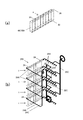
- FIG. 1A is a front view showing the membrane module set
- FIG. 1B is a left side view showing the membrane module set
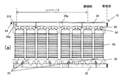
- FIG. 2A is a schematic diagram of a membrane module set
- FIG. 2B is a schematic diagram of a membrane separation device including a plurality of membrane module sets.
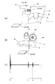
- FIG. 3A shows a film defect inspection method for the film module set, and is a front view of the main part of the sensor installation part
- FIG. 3B is a side view of the main part of the sensor installation part
- FIG. It is a signal explanatory view under inspection.
- FIG. 4 is an explanatory view of the membrane module set showing the positions of the membrane modules where the membrane breakage or the sealing failure occurs.
- FIG. 5A shows a defect inspection method for the membrane separation device, and is an explanatory diagram of the inspection device attached to the filtered water large pipe of the membrane separation device
- FIG. 5B shows a defect inspection method for the membrane separation device
- FIG. 5C is an explanatory diagram of the inspection image at the time of normality
- FIG. 5C is an explanatory diagram of the inspection image at the time of abnormality, showing the defect inspection method for the membrane separation device.
- FIG. 1A and 1B illustrate a film module set 1 to which the film defect inspection method according to the present invention is applied.
- the membrane module set 1 includes eight membrane modules 20, a raw water header pipe 22 that is a raw water supply pipe that supplies raw water to each membrane module 20, and a cleaning air or water or chemical solution that is supplied to each membrane module 20.
- a cleaning header pipe 24 that is an air pipe and a filtered water header pipe 26 that is a treated water pipe that collects the filtered water of each membrane module 20 are provided.
- Each membrane module 20 is composed of a membrane casing 100 and a membrane element 2 (shown by a chain line in FIG. 1B) housed in the membrane casing 100.
- the membrane casing 100 includes a base 30 and a base 30.
- the casing body 40, the upper lid body 50, the support portion 60 supported by the casing body 40, and the relative position of the support portion 60 and the upper lid body 50 is adjustable and held along the axial direction of the casing body 40.
- the holding unit 70 and the like are provided.
- the membrane element 2 is housed in the casing body 40 in a state where the membrane element 2 is pressed between the base 30 and the upper lid 50 via the seal members P respectively.
- the raw water supplied from the raw water header pipe 22 is filtered by the membrane element 2, and the filtered water passes through the gap between the inner wall of the casing body 40 and the membrane element 2 and is filtered from the filtered water outflow pipe 54 formed in the upper lid 50. Water is collected in the header pipe 26.
- the base 30, the casing body 40, the upper lid 50, the support portion 60, the holding portion 70, and the like may be made of metal, resin, or the like as long as they can withstand the pressure of the filtration process and the cleaning process, and the filtered water header pipe 26
- the piping such as is made of a resin suitable for the workability and inspection of a film breakage and a seal defect described later, for example, ABS resin or polyvinyl chloride resin.
- the membrane element 2 can be any filtration membrane such as a microfiltration membrane, an ultrafiltration membrane, or a nanofiltration membrane that blocks particles or polymers of a predetermined size depending on the application, and cellulose acetate or cellulose acetate can be used as the material of the filtration membrane.
- An organic film such as a hollow fiber film using polyimide or the like, or a porous inorganic film using a ceramic material can be used.
- the filtration step in which foreign matter is removed by the filtration membrane layer on the inner wall of the fluid passage hole formed in the membrane element 2 proceeds and flows out from the surface of the membrane element 2.
- the filtered water is guided to the filtered water outflow pipe 54 through the space formed between the peripheral surface of the membrane element 2 and the inner wall surface of the casing body 40, and is collected in the filtered water header pipe 26.
- a plurality of membrane modules 20, eight membrane modules 20 in the present embodiment, are connected in parallel below the straight pipe portion of the filtered water header pipe 26 that is a treated water pipe extending in the horizontal direction to form the membrane module set 1. There is.
- FIG. 2A shows a simplified schematic view of the above-mentioned membrane module set 1
- FIG. 2B shows a membrane module set 1 in which a plurality of membrane modules 20 are connected in parallel to a filtered water header pipe 26.
- the schematic diagram of the membrane separation apparatus 200 provided with two or more is shown.
- Eight membrane module sets 1 are installed per stage in a frame that has a vertically long rectangular parallelepiped and is configured in four stages in the vertical direction.
- the raw water header pipe 22, the washing header pipe 24, and the filtered water of each membrane module set 1 are installed.
- Each of the header pipes 26 is connected to a large raw water pipe 22C, a large washing pipe 24C, and a large filtered water pipe 26C which is a large treated water pipe via relay pipes 22A, 24A, 26A.
- the film defect inspection method according to the present invention it is possible to individually specify the film module 20 in which the film breakage or the sealing failure has occurred, and quickly replace the abnormal film module 20. become.
- the tube end portion 26 e on the side opposite to the side connected to the filtered water large pipe 26 A has a pipe end surface 26 f A flange portion 26g for pipe connection having a slightly larger diameter is formed to extend.
- the filtered water header pipe 26 functions as a gas detection pipe
- the filtered water large pipe 26A functions as a gas detection large pipe.
- FIG. 3( b) shows a film defect inspection device 300 attached to the film module set 1.
- the film defect inspection device 300 includes an ultrasonic sensor 310 and a signal processing unit 320.
- the ultrasonic sensor 310 is configured by incorporating an ultrasonic wave transmitting unit and an ultrasonic wave receiving unit, and is installed so as to come into contact with the central portion of the end surface of the tube end portion 26e.
- Filtered water header pipe 26 is filled with water, raw water is supplied from the raw water header pipe 22 communicating with the primary side space of the membrane module to the membrane element 2 in a state of pressurizing air into the membrane element 2, treated water filtered by a filtration membrane
- the ultrasonic sensor 310 is brought into contact with the tube end surface 26f of the filtered water header tube 26 that communicates with the secondary side space of the membrane module from which is extracted.
- an ultrasonic wave is transmitted from the ultrasonic wave transmitting unit along the axial direction of the filtered water header pipe 26, and a reflected wave for the ultrasonic wave is detected by the ultrasonic wave receiving unit.
- the signal processing unit determines whether or not any one of the membrane modules 20 connected to the filtered water header pipe 26 has a defect, based on the delay time from the ultrasonic wave transmission time to the reflected wave detection time. If the membrane module 20 has a defect, air leaks from the defective portion, bubbles flow into the filtered water header pipe 26 through the filtered water outflow pipe 54, and ultrasonic waves reflected by the bubbles are ultrasonically reflected by the ultrasonic wave reception unit. To be detected.
- FIG. 3C shows a waveform when the reflected wave of the ultrasonic wave transmitted from the ultrasonic wave transmitting unit at time t0 is detected by the ultrasonic wave receiving unit at time t1 and time t2.
- the reflected wave detected at time t2 is the reflection from the pipe wall of the filtered water relay pipe 26A to which the filtered water header pipe 26 is connected.
- the signal processing unit 320 connects the filter water header pipe 26 at a position close to the axial direction position (the position is calculated by (v ⁇ t1)/2 as the ultrasonic propagation velocity v) corresponding to the time t1. It is determined that the membrane module 20 that is present is abnormal.
- the axial position of the filtered water header pipe 26 corresponding to the time t1 with respect to the membrane module 20 constituting the membrane module set 1 is the seventh membrane module from the installation position of the ultrasonic sensor 310.
- An example is shown in which it is calculated to be around 20 and it is determined that leakage has occurred in the seventh membrane module 20.
- the filtered water header pipe 26 which is the treated water pipe, be made of a resin having excellent ultrasonic transmission characteristics. Therefore, the filtered water header pipe 26 is made of a resin pipe member such as ABS resin or polyvinyl chloride resin. If the pipe for contacting the ultrasonic sensor 310 is made of resin, ultrasonic waves propagate inside the pipe filled with water without being greatly attenuated at the pipe end, and sufficient detection accuracy can be obtained.
- the contact position of the ultrasonic sensor so that ultrasonic waves are emitted in the axial direction of the straight pipe portion of the filtered water header pipe 26.
- the film defect inspection device 300 is incorporated in all of the film module set 1, the economy may be impaired. Therefore, the membrane defect inspection method of the membrane separation device 200 described below is executed, and when an abnormality is detected in any of the membrane module sets 1, the membrane defect inspection method for each membrane module set 1 is manually executed. With such a configuration, economic efficiency is improved.
- the membrane defect inspection method of the membrane separation device 200 at least a part of the treated water large pipe 26C from which the treated water obtained in the entire membrane separation device 200 is taken out is transparent, and the treated water large pipe 26C is filled with water.
- the above-described film defect inspection method for the film module set 1C is performed.
- a part of the horizontal pipe flange-connected from the curved pipe at the upper end of the large treated water pipe 26 C is constituted by a transparent resin pipe 26 D, and the transparent resin pipe 26 D is placed in a horizontal posture. It is preferable to install an image pickup device 330 for photographing the inside of the tube.
- the leaked air bubbles flow into the transparent resin tube 26D and rise, and the water level changes.
- the image processing device 340 By analyzing the image including the gas-liquid interface captured by the image capturing device 330 by the image processing device 340, when a decrease in the water surface is detected, it can be determined that one of the membrane modules 20 is out of order. Become.
- a computer device in which image analysis software is installed can be preferably used as the image processing device 340, and the gas-liquid interface can be extracted by executing edge extraction processing or the like on the captured image, for example.
- the image processing device 340 installed at a remote place can analyze the image.
- the variation of the gas-liquid interface may be observed by directly visually confirming the transparent resin tube 26D without using the imaging device 330 or the image processing device 340.
- the filtered water header pipe 26 is located above the membrane module, and the filtered water header pipe 26 is used as a gas detection pipe.
- the raw water header pipe 22 is used as a gas detection pipe and the raw water large pipe 22C is used as a gas detection large pipe by injecting gas into the secondary side space of the membrane module.
- gas may be press-fitted from the filtered water extraction side of the membrane module, a protrusion may be provided at the end of the raw water supply pipe, and the ultrasonic sensor may be placed in contact with the protrusion.
- the cleaning air pipe can be used as the gas detection pipe and the cleaning large pipe 24C can be used as the gas detection large pipe, and the gas detection pipe dedicated to the film defect inspection and the gas detection large pipe can be used. It can be provided separately.
- the method for inspecting a membrane defect of a membrane module set according to the present invention is a horizontal method that communicates with a primary side space of a membrane module to which raw water is supplied or a secondary side space of a membrane module from which treated water obtained by membrane filtration of raw water is taken out.
- a film defect inspection method of a membrane module set in which a plurality of membrane modules are connected in parallel in a state where the gas detection pipe is filled with water
- An echo detection step of contacting an ultrasonic sensor including an ultrasonic wave receiving unit and detecting a reflected wave of the ultrasonic wave transmitted from the ultrasonic wave transmitting unit by the ultrasonic wave receiving unit.
- Membrane module set 2 Membrane element 20: Membrane module 22: Raw water header pipe (raw water supply pipe) 24: Wash header pipe (wash air pipe) 26: (Processed water pipe) Filtered water header pipe 26C: (Large treated water pipe) Large filtered water pipe 40: Casing (main body) 50: Casing (upper lid) 54: Filtered water outflow pipe 60: Support part
Landscapes
- Physics & Mathematics (AREA)
- Chemical & Material Sciences (AREA)
- General Physics & Mathematics (AREA)
- Engineering & Computer Science (AREA)
- Life Sciences & Earth Sciences (AREA)
- Chemical Kinetics & Catalysis (AREA)
- Analytical Chemistry (AREA)
- Biochemistry (AREA)
- Pathology (AREA)
- Immunology (AREA)
- General Health & Medical Sciences (AREA)
- Health & Medical Sciences (AREA)
- Acoustics & Sound (AREA)
- Organic Chemistry (AREA)
- Water Supply & Treatment (AREA)
- Quality & Reliability (AREA)
- Theoretical Computer Science (AREA)
- Environmental & Geological Engineering (AREA)
- Hydrology & Water Resources (AREA)
- Computer Vision & Pattern Recognition (AREA)
- Separation Using Semi-Permeable Membranes (AREA)
- Investigating Or Analyzing Materials By The Use Of Ultrasonic Waves (AREA)
Abstract
L'invention concerne un procédé de recherche de défauts de membranes, lequel permet une automatisation de la détection d'une déchirure, d'un défaut d'étanchéité etc. d'une membrane , ainsi qu'une détection sélective d'un module membranaire dans lequel est apparu un défaut d'étanchéité, une déchirure etc. Selon ce procédé de recherche de défauts de membranes, un ensemble de modules membranaires: est en communication avec un espace côté primaire d'un module membranaire dans lequel une eau brute est amenée ou avec un espace côté secondaire d'un module membranaire dans lequel une eau traitée, soit de l'eau brute ayant été soumise à une filtration membranaire, est extraite; et comporte en aval de la partie droite d'un tuyau de détection de gaz s'étendant en direction horizontale, plusieurs modules membranaires reliés en parallèle. Ce procédé de recherche de défauts de membranes comporte: une étape d'introduction en force de gaz consistant, dans un état dans lequel le tuyau de détection de gaz est rempli d'eau, à introduire un gaz dans un espace situé à l'opposé de l'espace côté primaire ou de l'espace côté secondaire communiquant avec le tuyau de détection de gaz du module membranaire; et une étape de détection d'écho dans laquelle un capteur d'ondes ultrasonores constitué d'une partie émission d'ondes ultrasonores et d'une partie réception d'ondes ultrasonores est mis en contact avec l'extrémité de la partie droite du tuyau de détection de gaz, et des ondes réfléchies opposées aux ondes ultrasonores émises par la partie émission d'ondes ultrasonores sont détectées à l'aide de la partie réception d'ondes ultrasonores.
Priority Applications (3)
| Application Number | Priority Date | Filing Date | Title |
|---|---|---|---|
| US17/296,069 US11890581B2 (en) | 2018-12-12 | 2019-12-03 | Membrane defect inspection method and membrane defect inspection device |
| CN201980071405.5A CN113164877A (zh) | 2018-12-12 | 2019-12-03 | 膜缺陷检查方法及膜缺陷检查装置 |
| EP19895442.2A EP3895789A4 (fr) | 2018-12-12 | 2019-12-03 | Procédé de recherche de défauts de membranes et dispositif de recherche de défauts de membranes |
Applications Claiming Priority (2)
| Application Number | Priority Date | Filing Date | Title |
|---|---|---|---|
| JP2018-232096 | 2018-12-12 | ||
| JP2018232096A JP6503131B1 (ja) | 2018-12-12 | 2018-12-12 | 膜欠陥検査方法及び膜欠陥検査装置 |
Publications (1)
| Publication Number | Publication Date |
|---|---|
| WO2020121881A1 true WO2020121881A1 (fr) | 2020-06-18 |
Family
ID=66166708
Family Applications (1)
| Application Number | Title | Priority Date | Filing Date |
|---|---|---|---|
| PCT/JP2019/047120 WO2020121881A1 (fr) | 2018-12-12 | 2019-12-03 | Procédé de recherche de défauts de membranes et dispositif de recherche de défauts de membranes |
Country Status (5)
| Country | Link |
|---|---|
| US (1) | US11890581B2 (fr) |
| EP (1) | EP3895789A4 (fr) |
| JP (1) | JP6503131B1 (fr) |
| CN (1) | CN113164877A (fr) |
| WO (1) | WO2020121881A1 (fr) |
Cited By (1)
| Publication number | Priority date | Publication date | Assignee | Title |
|---|---|---|---|---|
| CN117405677A (zh) * | 2023-12-14 | 2024-01-16 | 常州树杰塑业有限公司 | 一种塑料薄膜裂缝检测装置 |
Families Citing this family (2)
| Publication number | Priority date | Publication date | Assignee | Title |
|---|---|---|---|---|
| CN111637046A (zh) * | 2020-05-25 | 2020-09-08 | 汕头超声印制板(二厂)有限公司 | 一种气动隔膜泵膜片破损的在线无损检测方法 |
| US11625853B2 (en) * | 2021-04-12 | 2023-04-11 | Saudi Arabian Oil Company | Spot detection algorithm for external pipeline inspection applications |
Citations (8)
| Publication number | Priority date | Publication date | Assignee | Title |
|---|---|---|---|---|
| JPH0975690A (ja) * | 1995-09-11 | 1997-03-25 | Nkk Corp | 水処理フィルタ損傷検出方法とその装置、及びその装置を備える水処理装置 |
| JPH11311596A (ja) | 1998-04-28 | 1999-11-09 | Asahi Chem Ind Co Ltd | 中空糸状膜の膜切れ検知方法 |
| JP2001269551A (ja) | 2000-03-27 | 2001-10-02 | Suido Kiko Kaisha Ltd | 浄水処理装置の透過膜モジュールの破断検知方法 |
| JP2007155458A (ja) * | 2005-12-02 | 2007-06-21 | Hitachi Ltd | ろ過膜破損検出器、膜ろ過装置およびろ過膜破損検出方法 |
| JP2007240373A (ja) | 2006-03-09 | 2007-09-20 | Toshiba It & Control Systems Corp | 水処理用ろ過システムの膜損傷検出装置及び膜損傷検出方法 |
| KR100950218B1 (ko) * | 2009-09-09 | 2010-03-29 | 주식회사 한미엔텍 | 중공사막 모듈의 파손 감지장치 |
| JP2013154293A (ja) * | 2012-01-30 | 2013-08-15 | Mitsubishi Heavy Ind Ltd | 逆浸透膜淡水化装置の検査装置、及び検査方法、並びに逆浸透膜淡水化システム |
| KR20130137809A (ko) * | 2012-06-08 | 2013-12-18 | 정해두 | 여과막 파손 감지용 감지센서가 부착된 기능성 정수장 배관 |
Family Cites Families (7)
| Publication number | Priority date | Publication date | Assignee | Title |
|---|---|---|---|---|
| JPH082407B2 (ja) | 1988-05-06 | 1996-01-17 | 栗田工業株式会社 | ▲ろ▼過装置 |
| EP1021240A1 (fr) * | 1997-09-30 | 2000-07-26 | Pall Corporation | Dispositifs et procedes servant a localiser des filtres defectueux dans une pluralite de filtres |
| US7025883B1 (en) * | 2003-09-30 | 2006-04-11 | Ok Technologies, Llc | Autotrofic sulfur denitration chamber and calcium reactor |
| JP5055146B2 (ja) * | 2007-08-27 | 2012-10-24 | 株式会社日立製作所 | 膜ろ過装置及び膜ろ過装置の膜損傷検知方法 |
| US20090299651A1 (en) * | 2008-05-29 | 2009-12-03 | Hach Company | Filtration testing system |
| CN201832565U (zh) | 2010-11-03 | 2011-05-18 | 国电龙源南京膜技术有限公司 | 膜组件检漏装置 |
| CN104568333A (zh) | 2015-01-26 | 2015-04-29 | 深圳市远望工业自动化设备有限公司 | 一种箱体超声波检漏设备 |
-
2018
- 2018-12-12 JP JP2018232096A patent/JP6503131B1/ja active Active
-
2019
- 2019-12-03 EP EP19895442.2A patent/EP3895789A4/fr active Pending
- 2019-12-03 CN CN201980071405.5A patent/CN113164877A/zh active Pending
- 2019-12-03 WO PCT/JP2019/047120 patent/WO2020121881A1/fr unknown
- 2019-12-03 US US17/296,069 patent/US11890581B2/en active Active
Patent Citations (8)
| Publication number | Priority date | Publication date | Assignee | Title |
|---|---|---|---|---|
| JPH0975690A (ja) * | 1995-09-11 | 1997-03-25 | Nkk Corp | 水処理フィルタ損傷検出方法とその装置、及びその装置を備える水処理装置 |
| JPH11311596A (ja) | 1998-04-28 | 1999-11-09 | Asahi Chem Ind Co Ltd | 中空糸状膜の膜切れ検知方法 |
| JP2001269551A (ja) | 2000-03-27 | 2001-10-02 | Suido Kiko Kaisha Ltd | 浄水処理装置の透過膜モジュールの破断検知方法 |
| JP2007155458A (ja) * | 2005-12-02 | 2007-06-21 | Hitachi Ltd | ろ過膜破損検出器、膜ろ過装置およびろ過膜破損検出方法 |
| JP2007240373A (ja) | 2006-03-09 | 2007-09-20 | Toshiba It & Control Systems Corp | 水処理用ろ過システムの膜損傷検出装置及び膜損傷検出方法 |
| KR100950218B1 (ko) * | 2009-09-09 | 2010-03-29 | 주식회사 한미엔텍 | 중공사막 모듈의 파손 감지장치 |
| JP2013154293A (ja) * | 2012-01-30 | 2013-08-15 | Mitsubishi Heavy Ind Ltd | 逆浸透膜淡水化装置の検査装置、及び検査方法、並びに逆浸透膜淡水化システム |
| KR20130137809A (ko) * | 2012-06-08 | 2013-12-18 | 정해두 | 여과막 파손 감지용 감지센서가 부착된 기능성 정수장 배관 |
Non-Patent Citations (1)
| Title |
|---|
| See also references of EP3895789A4 |
Cited By (2)
| Publication number | Priority date | Publication date | Assignee | Title |
|---|---|---|---|---|
| CN117405677A (zh) * | 2023-12-14 | 2024-01-16 | 常州树杰塑业有限公司 | 一种塑料薄膜裂缝检测装置 |
| CN117405677B (zh) * | 2023-12-14 | 2024-03-22 | 常州树杰塑业有限公司 | 一种塑料薄膜裂缝检测装置 |
Also Published As
| Publication number | Publication date |
|---|---|
| CN113164877A (zh) | 2021-07-23 |
| JP6503131B1 (ja) | 2019-04-17 |
| JP2020093208A (ja) | 2020-06-18 |
| US20210394123A1 (en) | 2021-12-23 |
| EP3895789A1 (fr) | 2021-10-20 |
| EP3895789A4 (fr) | 2022-08-10 |
| US11890581B2 (en) | 2024-02-06 |
Similar Documents
| Publication | Publication Date | Title |
|---|---|---|
| WO2020121881A1 (fr) | Procédé de recherche de défauts de membranes et dispositif de recherche de défauts de membranes | |
| WO2001045829A1 (fr) | Procede et appareil pour controler le bon fonctionnement de membranes filtrantes | |
| JP4669407B2 (ja) | 多孔質中空糸膜の欠陥検査装置 | |
| JP2007240373A (ja) | 水処理用ろ過システムの膜損傷検出装置及び膜損傷検出方法 | |
| AU737828B2 (en) | Process for monitoring the integrity of hollow fibre filtration modules | |
| JPH05137977A (ja) | 膜濾過装置の分離膜破損検知方法 | |
| US20090299651A1 (en) | Filtration testing system | |
| JP2016019932A (ja) | スパイラル膜圧力容器内のモニタリング装置およびモニタリング方法 | |
| KR20040043180A (ko) | 막 여과 유닛들의 완전성을 체크하는 방법 및 장치 | |
| KR101753453B1 (ko) | 중공사막 여과장치 및 그의 여과막 손상 감지방법 | |
| JP2007296516A (ja) | 膜ろ過システムのリーク検知方法及び装置 | |
| WO2020121880A1 (fr) | Procédé de recherche de défauts de membranes et dispositif de recherche de défauts de membranes | |
| KR100950218B1 (ko) | 중공사막 모듈의 파손 감지장치 | |
| JP2006218372A (ja) | 膜分離装置 | |
| JP4277052B1 (ja) | 膜ろ過装置の運転制御方法 | |
| JP2000342937A (ja) | 中空糸膜ろ過装置の膜損傷検知装置及び膜損傷検知方法 | |
| JP4816611B2 (ja) | 浸漬型中空糸膜モジュールにおける損傷膜の特定方法 | |
| JP2001269551A (ja) | 浄水処理装置の透過膜モジュールの破断検知方法 | |
| JP2000342936A (ja) | 中空糸膜ろ過装置の膜損傷検知方法及び膜損傷検知装置 | |
| JP2005296908A (ja) | 膜ろ過装置及び膜破断の検知方法 | |
| JPH0975690A (ja) | 水処理フィルタ損傷検出方法とその装置、及びその装置を備える水処理装置 | |
| JP2004188252A (ja) | 膜ろ過装置およびその運転方法 | |
| JP4461288B2 (ja) | ろ過膜異常検知方法およびその装置 | |
| JP2016036766A (ja) | 中空糸膜モジュールの健全性診断方法、及び健全性保持方法 | |
| KR101178923B1 (ko) | 광섬유 센서를 이용한 여과막 손상 감지장치 및 방법 |
Legal Events
| Date | Code | Title | Description |
|---|---|---|---|
| 121 | Ep: the epo has been informed by wipo that ep was designated in this application |
Ref document number: 19895442 Country of ref document: EP Kind code of ref document: A1 |
|
| NENP | Non-entry into the national phase |
Ref country code: DE |
|
| ENP | Entry into the national phase |
Ref document number: 2019895442 Country of ref document: EP Effective date: 20210712 |