WO2020121693A1 - 太陽電池モジュール - Google Patents
太陽電池モジュール Download PDFInfo
- Publication number
- WO2020121693A1 WO2020121693A1 PCT/JP2019/043497 JP2019043497W WO2020121693A1 WO 2020121693 A1 WO2020121693 A1 WO 2020121693A1 JP 2019043497 W JP2019043497 W JP 2019043497W WO 2020121693 A1 WO2020121693 A1 WO 2020121693A1
- Authority
- WO
- WIPO (PCT)
- Prior art keywords
- solar cell
- light
- receiving side
- solar
- cell module
- Prior art date
Links
- 239000003566 sealing material Substances 0.000 claims abstract description 45
- 239000000463 material Substances 0.000 claims description 22
- 238000007789 sealing Methods 0.000 claims description 10
- 239000008393 encapsulating agent Substances 0.000 claims description 2
- 238000013461 design Methods 0.000 abstract description 10
- 230000001681 protective effect Effects 0.000 abstract description 7
- 230000000052 comparative effect Effects 0.000 description 17
- 239000004065 semiconductor Substances 0.000 description 15
- 239000000758 substrate Substances 0.000 description 13
- 238000000034 method Methods 0.000 description 12
- 239000010410 layer Substances 0.000 description 10
- 238000012986 modification Methods 0.000 description 7
- 230000004048 modification Effects 0.000 description 7
- 229920005989 resin Polymers 0.000 description 7
- 239000011347 resin Substances 0.000 description 7
- 230000002093 peripheral effect Effects 0.000 description 6
- 238000010248 power generation Methods 0.000 description 5
- YCKRFDGAMUMZLT-UHFFFAOYSA-N Fluorine atom Chemical compound [F] YCKRFDGAMUMZLT-UHFFFAOYSA-N 0.000 description 4
- 230000007423 decrease Effects 0.000 description 4
- 229910052731 fluorine Inorganic materials 0.000 description 4
- 239000011737 fluorine Substances 0.000 description 4
- VGGSQFUCUMXWEO-UHFFFAOYSA-N Ethene Chemical compound C=C VGGSQFUCUMXWEO-UHFFFAOYSA-N 0.000 description 3
- 239000005977 Ethylene Substances 0.000 description 3
- 239000000919 ceramic Substances 0.000 description 3
- 238000006243 chemical reaction Methods 0.000 description 3
- 238000011156 evaluation Methods 0.000 description 3
- 239000003973 paint Substances 0.000 description 3
- -1 polyethylene terephthalate Polymers 0.000 description 3
- 229920000139 polyethylene terephthalate Polymers 0.000 description 3
- 239000005020 polyethylene terephthalate Substances 0.000 description 3
- 229920002799 BoPET Polymers 0.000 description 2
- 239000004698 Polyethylene Substances 0.000 description 2
- 239000011888 foil Substances 0.000 description 2
- 239000011521 glass Substances 0.000 description 2
- 238000009413 insulation Methods 0.000 description 2
- 239000007788 liquid Substances 0.000 description 2
- 238000005259 measurement Methods 0.000 description 2
- 229920000573 polyethylene Polymers 0.000 description 2
- 239000007787 solid Substances 0.000 description 2
- 238000001228 spectrum Methods 0.000 description 2
- 230000000007 visual effect Effects 0.000 description 2
- XLYOFNOQVPJJNP-UHFFFAOYSA-N water Substances O XLYOFNOQVPJJNP-UHFFFAOYSA-N 0.000 description 2
- KOMNUTZXSVSERR-UHFFFAOYSA-N 1,3,5-tris(prop-2-enyl)-1,3,5-triazinane-2,4,6-trione Chemical compound C=CCN1C(=O)N(CC=C)C(=O)N(CC=C)C1=O KOMNUTZXSVSERR-UHFFFAOYSA-N 0.000 description 1
- 229920000178 Acrylic resin Polymers 0.000 description 1
- 239000004925 Acrylic resin Substances 0.000 description 1
- FERIUCNNQQJTOY-UHFFFAOYSA-M Butyrate Chemical compound CCCC([O-])=O FERIUCNNQQJTOY-UHFFFAOYSA-M 0.000 description 1
- FERIUCNNQQJTOY-UHFFFAOYSA-N Butyric acid Natural products CCCC(O)=O FERIUCNNQQJTOY-UHFFFAOYSA-N 0.000 description 1
- 229920000089 Cyclic olefin copolymer Polymers 0.000 description 1
- XTXRWKRVRITETP-UHFFFAOYSA-N Vinyl acetate Chemical compound CC(=O)OC=C XTXRWKRVRITETP-UHFFFAOYSA-N 0.000 description 1
- NIXOWILDQLNWCW-UHFFFAOYSA-N acrylic acid group Chemical group C(C=C)(=O)O NIXOWILDQLNWCW-UHFFFAOYSA-N 0.000 description 1
- 229910052782 aluminium Inorganic materials 0.000 description 1
- XAGFODPZIPBFFR-UHFFFAOYSA-N aluminium Chemical compound [Al] XAGFODPZIPBFFR-UHFFFAOYSA-N 0.000 description 1
- 230000015572 biosynthetic process Effects 0.000 description 1
- 230000015556 catabolic process Effects 0.000 description 1
- 239000011247 coating layer Substances 0.000 description 1
- 229920001577 copolymer Polymers 0.000 description 1
- 238000006731 degradation reaction Methods 0.000 description 1
- 230000000694 effects Effects 0.000 description 1
- 230000012447 hatching Effects 0.000 description 1
- 238000005286 illumination Methods 0.000 description 1
- 239000011810 insulating material Substances 0.000 description 1
- 229910052751 metal Inorganic materials 0.000 description 1
- 239000002184 metal Substances 0.000 description 1
- 229920000515 polycarbonate Polymers 0.000 description 1
- 239000004417 polycarbonate Substances 0.000 description 1
- 229920005668 polycarbonate resin Polymers 0.000 description 1
- 239000004431 polycarbonate resin Substances 0.000 description 1
- 229920005672 polyolefin resin Polymers 0.000 description 1
- 229920001296 polysiloxane Polymers 0.000 description 1
- 229910052814 silicon oxide Inorganic materials 0.000 description 1
- 229920002050 silicone resin Polymers 0.000 description 1
- 230000003595 spectral effect Effects 0.000 description 1
- 229920002803 thermoplastic polyurethane Polymers 0.000 description 1
- 238000000870 ultraviolet spectroscopy Methods 0.000 description 1
- 229920002554 vinyl polymer Polymers 0.000 description 1
- 239000004711 α-olefin Substances 0.000 description 1
Images


Classifications
-
- H—ELECTRICITY
- H01—ELECTRIC ELEMENTS
- H01L—SEMICONDUCTOR DEVICES NOT COVERED BY CLASS H10
- H01L31/00—Semiconductor devices sensitive to infrared radiation, light, electromagnetic radiation of shorter wavelength or corpuscular radiation and specially adapted either for the conversion of the energy of such radiation into electrical energy or for the control of electrical energy by such radiation; Processes or apparatus specially adapted for the manufacture or treatment thereof or of parts thereof; Details thereof
- H01L31/04—Semiconductor devices sensitive to infrared radiation, light, electromagnetic radiation of shorter wavelength or corpuscular radiation and specially adapted either for the conversion of the energy of such radiation into electrical energy or for the control of electrical energy by such radiation; Processes or apparatus specially adapted for the manufacture or treatment thereof or of parts thereof; Details thereof adapted as photovoltaic [PV] conversion devices
- H01L31/042—PV modules or arrays of single PV cells
- H01L31/048—Encapsulation of modules
-
- H—ELECTRICITY
- H01—ELECTRIC ELEMENTS
- H01L—SEMICONDUCTOR DEVICES NOT COVERED BY CLASS H10
- H01L31/00—Semiconductor devices sensitive to infrared radiation, light, electromagnetic radiation of shorter wavelength or corpuscular radiation and specially adapted either for the conversion of the energy of such radiation into electrical energy or for the control of electrical energy by such radiation; Processes or apparatus specially adapted for the manufacture or treatment thereof or of parts thereof; Details thereof
- H01L31/04—Semiconductor devices sensitive to infrared radiation, light, electromagnetic radiation of shorter wavelength or corpuscular radiation and specially adapted either for the conversion of the energy of such radiation into electrical energy or for the control of electrical energy by such radiation; Processes or apparatus specially adapted for the manufacture or treatment thereof or of parts thereof; Details thereof adapted as photovoltaic [PV] conversion devices
- H01L31/054—Optical elements directly associated or integrated with the PV cell, e.g. light-reflecting means or light-concentrating means
-
- Y—GENERAL TAGGING OF NEW TECHNOLOGICAL DEVELOPMENTS; GENERAL TAGGING OF CROSS-SECTIONAL TECHNOLOGIES SPANNING OVER SEVERAL SECTIONS OF THE IPC; TECHNICAL SUBJECTS COVERED BY FORMER USPC CROSS-REFERENCE ART COLLECTIONS [XRACs] AND DIGESTS
- Y02—TECHNOLOGIES OR APPLICATIONS FOR MITIGATION OR ADAPTATION AGAINST CLIMATE CHANGE
- Y02E—REDUCTION OF GREENHOUSE GAS [GHG] EMISSIONS, RELATED TO ENERGY GENERATION, TRANSMISSION OR DISTRIBUTION
- Y02E10/00—Energy generation through renewable energy sources
- Y02E10/50—Photovoltaic [PV] energy
- Y02E10/52—PV systems with concentrators
Definitions
- the present invention relates to a solar cell module.
- the solar cells are placed apart from each other in order to ensure insulation between multiple solar cells. Therefore, a gap is generated between the solar cells, and the designability is deteriorated.
- Patent Document 1 describes a solar cell module in which a black-colored pattern having a similar color to the solar cells is provided in a region corresponding to a gap between the solar cells on the back surface side of the solar cells. (See, for example, FIG. 7). This improves the design of the solar cell module.
- the present invention also aims to provide a solar cell module whose design can be improved.
- the solar battery module according to the present invention is a solar battery module including a plurality of solar battery cells, or a solar battery module including a plurality of solar battery strings that electrically connect the plurality of solar battery cells by using a shingling method.
- a plurality of solar cells or a light-receiving side protection member that protects the light-receiving surface side of the solar cell string; and a back-side protection member that protects a back surface side opposite to the light-receiving surface side of the plurality of solar cells or the solar cell string;
- the solar cell or the solar cell string and a light-receiving side sealing member that is disposed between the solar cell string and the light-receiving side protection member, and seals the plurality of solar cells or the solar cell string, and the plurality of solar cells or the solar cell string.
- the back side protection member Arranged between the back side protection member and a back side sealing material for sealing a plurality of solar cells or solar cell strings, the light receiving side protection member, the gap between the plurality of solar cells or a plurality of A first light receiving side pattern that overlaps the gap between the solar cell strings is formed, and the first light receiving side pattern has the same color or a similar color as the light receiving surface of the solar cell.
- the design of the solar cell module is improved.
- FIG. 6 is a sectional view taken along line VI-VI of the solar cell module according to the second embodiment shown in FIG. 5. It is sectional drawing of the solar cell module which concerns on a comparative example, Comprising: It is sectional drawing corresponding to the II-II line of FIG.
- FIG. 1 is a view of the solar cell module according to the first embodiment seen from the light receiving surface side
- FIG. 2 is a sectional view taken along the line II-II of the solar cell module according to the first embodiment shown in FIG.
- the solar cell module 100 includes a plurality of solar cells 1, a light-receiving side protection member 3, a backside protection member 4, a light-receiving side sealing material 5, and a backside sealing material 6. And a first light receiving side pattern 7.
- the solar cell 1 is, for example, a rectangular solar cell composed of one of a large-sized semiconductor substrate of a predetermined size divided.
- the predetermined size is a size determined by a predetermined size (for example, 6 inches) of the semiconductor wafer. For example, in the case of a 6-inch large-sized semiconductor substrate, this large-sized semiconductor substrate is divided into two or more and 10 or less in one predetermined direction.
- the solar battery cell 1 may be a square solar battery cell that is composed of a large-sized semiconductor substrate itself having a predetermined size.
- the solar cell 1 may be a double-sided electrode type or a backside electrode type.
- the plurality of solar cells 1 are arranged two-dimensionally in the X direction and the Y direction.
- the plurality of solar battery cells 1 are arranged apart from each other in the X direction and the Y direction in order to ensure insulation between the solar battery cells 1.
- the solar cell 1 is sandwiched by the light-receiving side protection member 3 and the back side protection member 4.
- a liquid or solid sealing material (light-receiving-side sealing material 5 and back-side sealing material 6) is filled between the light-receiving side protection member 3 and the back-side protection member 4, whereby a solar cell is provided.
- the cell 1 is sealed.
- the light-receiving side sealing material 5 and the back side sealing material 6 seal and protect the solar cell 1.
- the light-receiving side sealing material 5 is interposed between the light-receiving side surface of the solar cell 1 and the light-receiving side protection member 3.
- the back side sealing material 6 is interposed between the back side surface of the solar cell 1 and the back side protection member 4.
- the shapes of the light-receiving side sealing material 5 and the back side sealing material 6 are not particularly limited, and examples thereof include a sheet shape. This is because the sheet-shaped solar cell 1 can easily cover the front surface and the back surface thereof.
- the material of the light-receiving side sealing material 5 and the back side sealing material 6 is not particularly limited, but an insulating material having a property of transmitting light (translucency) is preferable. Further, the materials of the light-receiving side sealing material 5 and the back-side sealing material 6 preferably have adhesiveness for bonding the solar cell 1, the light-receiving side protection member 3 and the back side protection member 4. Examples of such a material include ethylene/vinyl acetate copolymer (EVA), ethylene/ ⁇ -olefin copolymer, ethylene/vinyl acetate/triallyl isocyanurate (EVAT), polyvinyl butyrate (PVB), and acrylic. A resin, a urethane resin, or a translucent resin such as a silicone resin can be used.
- EVA ethylene/vinyl acetate copolymer
- EVAT ethylene/ ⁇ -olefin copolymer
- PVAT ethylene/vinyl acetate/trially
- the light-receiving side protection member 3 covers the light-receiving surface of the solar battery cell 1 via the light-receiving side sealing material 5 to protect the solar battery cell 1.
- the shape of the light-receiving side protection member 3 is not particularly limited, but a plate-like or sheet-like shape is preferable from the viewpoint of indirectly covering the planar light-receiving surface.
- the material of the light-receiving side protection member 3 is not particularly limited, but a material that has translucency but has resistance to ultraviolet light as well as the light-receiving side sealing material 5 and the back side sealing material 6.
- Preferred examples include glass and transparent resins such as acrylic resin and polycarbonate resin.
- the surface of the light-receiving side protection member 3 may be processed into an uneven shape or may be covered with an antireflection coating layer. This is because the light-receiving side protection member 3 is difficult to reflect the received light and can guide a larger amount of light to the solar battery cell 1 when configured as described above.
- the back side protection member 4 covers the back surface of the solar cell 1 via the back side sealing material 6 to protect the solar cell string 2.
- the shape of the back side protection member 4 is not particularly limited, but like the light-receiving side protection member 3, a plate shape or a sheet shape is preferable because it indirectly covers the planar back surface.
- the material of the back side protection member 4 is not particularly limited, but a material that prevents ingress of water and the like (high water impermeability) is preferable.
- a resin film such as polyethylene terephthalate (PET), polyethylene (PE), an olefin resin, a fluorine-containing resin, or a silicone-containing resin, or a translucent plate-shaped resin member such as glass, polycarbonate, or acryl,
- PET polyethylene terephthalate
- PE polyethylene
- PE polyethylene
- an olefin resin a fluorine-containing resin
- silicone-containing resin or a translucent plate-shaped resin member such as glass, polycarbonate, or acryl
- a laminate with a metal foil such as an aluminum foil can be used.
- a first light receiving side pattern 7 is arranged on the light receiving side sealing member 5 side of the light receiving side protection member 3.
- the first light receiving side pattern 7 is formed so as to overlap the gap between the adjacent solar cells 1 and the edge portion of the solar cell 1 when viewed from the light receiving side.
- the edge portion of the solar battery cell 1 may be at least a part of the peripheral edge portion of the solar battery cell 1, or may be the entire peripheral edge portion of the solar battery cell 1.
- it is preferable that the first light receiving side pattern 7 is superposed on the edge portion of the solar cell 1 corresponding to the peripheral portion of the large-sized semiconductor substrate described above.
- All or at least the light receiving surface of the first light receiving side pattern 7 has the same color or a similar color as the light receiving surface of the solar cell 1.
- the first light receiving side pattern 7 is black or black.
- the first light-receiving side pattern 7 of black or black is CIE1976L*a*b* color system, L* is 50 or less, a* is -50 or more and +50 or less, and b* is -50. It is above +50.
- a reflection spectrum in the visible light region measured using an analyzer such as a spectrocolorimeter, a spectrocolor difference meter, a spectrocolorimeter, or an ultraviolet-visible spectrophotometer is used. ing. Then, regarding the digitization of the color based on the reflection spectrum, the CIE1976 L*a*b* color system (L*: light [+] to dark [-], which is standardized by the CIE (International Commission on Illumination), a*: reddish [+] to greenish [-], b*: yellow [+] to bluish [-]) were used.
- the method for measuring the reflection color was a method (SCE: Specular Component Exclude) which has a high correlation with the human visual evaluation and which detects only diffuse reflection light, and D65 was used as the measurement light source.
- the visual field used for calculating the reflected color is not particularly limited, and for example, 10 degrees or 2 degrees defined by CIE may be used.
- the material of the first light receiving side pattern 7 examples include ceramic paint, fluorine film, PET film and the like.
- the first light-receiving side pattern 7 is formed on the light-receiving side protection member 3 by using, for example, a printing method or an inkjet method.
- the first light receiving side pattern 7 may be arranged on the atmosphere side of the light receiving side protection member 3. From the viewpoint of weather resistance (degradation of the pattern), the first light-receiving side pattern 7 is preferably formed on the light-receiving side sealing material 5 side of the light-receiving side protection member 3.
- FIG. 7 shows a cross-sectional view of a solar cell module according to a comparative example.
- the solar cell module 100X of the comparative example includes the solar cell 1, the light-reception-side protection member 3, the back-side protection member 4, and the light-reception-side sealing in the solar cell module 100 of the first embodiment shown in FIG.
- the solar cell 1X, the light receiving side protection member 3X, the back side protection member 4X, the light receiving side sealing material 5X, and the back side sealing material 6X corresponding to these are provided.
- the solar cell module 100X of the comparative example is different from the first embodiment in that the back side protection member 4X is formed with the back side pattern 7X overlapping the gaps between the plurality of solar cells 1X.
- the back side pattern 7X has the same color or a similar color (for example, black or black) as the light receiving surface of the solar cell 1X.
- the light-receiving side protection member 3 is formed with the first light-receiving side pattern 7 overlapping the gap between the plurality of solar cells 1.
- the 1 light receiving side pattern 7 has the same color or a similar color (for example, black or black) as the light receiving surface of the solar cell 1.
- the black system of the first light-receiving side pattern 7 is more Also looks more blackish. Therefore, the design of the solar cell module 100 is improved as compared with the comparative example.
- the solar cell module 100 of the first embodiment the light incident on the edge portion (details will be described later) of the solar cell 1 having a relatively low photoelectric conversion efficiency is reduced. Therefore, the output of the solar cell module 100 is improved.
- a solar battery cell has a semiconductor layer, a TCO (Transparent Conductive Oxide) layer, and an antireflection layer (eg, SiO, SiN, or the like) on a large-sized semiconductor substrate (for example, a substantially square shape) having a predetermined size (for example, 6 inches).
- a large-sized semiconductor substrate for example, a substantially square shape
- the film thickness of the edge portion of the large-sized semiconductor substrate may be smaller than the film thickness of the inside of the large-sized semiconductor substrate other than the edge portion.
- the film thickness at the edge of the large-sized semiconductor substrate near the pins may be reduced.
- the film thickness is reduced in this way (for example, when the thickness of the antireflection layer or the TCO layer is reduced on the double-sided electrode side, or when the thickness of the antireflection layer is reduced on the backside electrode side),
- the color is different from other parts, and the designability of the solar cell module deteriorates.
- the first light-receiving side pattern 7 is also overlapped with the edge portion of the solar cell 1.
- the edge of the solar cell 1 whose film thickness may be thin is hidden under the first light receiving side pattern 7, and the design of the solar cell module 100 is further improved.
- the photoelectric conversion efficiency is lower near the edge of the large-sized semiconductor substrate than in the inside.
- the edge of the solar cell 1 having a low photoelectric conversion efficiency is hidden under the first light receiving side pattern 7, and the output of the solar cell module 100 is further improved.
- FIG. 3 is a cross-sectional view of the solar cell module according to Modification 1 of the first embodiment and is a cross-sectional view corresponding to line II-II in FIG. 1.
- a backside pattern 9 may be arranged on the backside sealing member 6 side of the backside protection member 4.
- the back side pattern 9 is formed so as to cover a part or all of the surface of the back side protection member 4.
- the back side pattern 9 is a color having a reflection characteristic for infrared light.
- the backside pattern 9 is white or white-based, or red-black or red-black-based.
- the material of the back side pattern 9 may be ceramic paint, fluorine film, PET film or the like.
- the back side pattern 9 is formed on the back side protection member 4 by using, for example, a printing method or an inkjet method.
- At least a part 6a of the back side sealing material 6 on the back side protection member 4 side may include a material having a reflection property with respect to infrared light.
- the part 6a of the backside encapsulant 6 may include a white or white-based material, or a red-black or red-black-based material.
- the light transmitted through the solar cell 1 is reflected by the back side pattern 9 of the back side protection member 4 or the part 6a of the back side sealing material 6 and re-enters the solar cell 1. Therefore, the output of the solar cell module 100 is improved.
- FIG. 4 is a cross-sectional view of the solar cell module according to Modification 2 of the first embodiment, which is a cross-sectional view corresponding to line II-II in FIG. 1.
- the second light receiving side pattern 8 may be arranged on the light receiving side sealing member 5 side of the light receiving side protection member 3.
- the second light receiving side pattern 8 is formed on the light receiving side sealing material 5 side of the first light receiving side pattern 7.
- the second light receiving side pattern 8 is a color having a reflection characteristic for infrared light.
- the second light-receiving side pattern 8 is white or white-based, or red-black or red-black-based.
- the material of the second light receiving side pattern 8 may be ceramic paint, fluorine-based film, PET-based film, or the like.
- the second light receiving side pattern 8 is formed on the first light receiving side pattern 7 of the back side protection member 4 by using, for example, a printing method or an inkjet method.
- the light transmitted through the solar battery cell is reflected by the second light receiving side pattern 8 of the light receiving side protection member 3 and re-enters the solar battery cell 1. Therefore, the output of the solar cell module 100 is improved while maintaining the effect of improving the designability by the first light-receiving side pattern 7.
- FIG. 5 is a view of the solar cell module according to the second embodiment as seen from the light receiving surface side
- FIG. 6 is a sectional view taken along line VI-VI of the solar cell module according to the second embodiment shown in FIG.
- the solar cells 1 are connected in series by partially overlapping the ends of the solar cells 1. Specifically, a part of one solar battery cell 1 on one end side of adjacent solar battery cells 1 and 1 overlaps with a part of the other solar battery cell 1 on the other end side. In this way, the solar cells 1 are electrically connected in this way, because the solar cells 1 have a stacking structure in which the solar cells 1 are uniformly inclined in a certain direction like roofing a roof. The method is called a shingling method. Further, the plurality of solar battery cells 1 connected in a string are referred to as a solar battery string.
- the solar cell string 2 is sandwiched between the light receiving side protection member 3 and the back side protection member 4.
- a liquid or solid sealing material (light-receiving-side sealing material 5 and back-side sealing material 6) is filled between the light-receiving side protection member 3 and the back-side protection member 4, whereby a solar cell is provided.
- the cell 1 is sealed.
- the light-receiving side sealing material 5 and the back side sealing material 6 seal and protect the solar cell string 2.
- the light-receiving side sealing material 5 is interposed between the light-receiving side surface of the solar cell string 2 and the light-receiving side protection member 3.
- the back side sealing material 6 is interposed between the back side surface of the solar cell string 2 and the back side protection member 4.
- the light-receiving side protection member 3 covers the light-receiving surface of the solar cell string 2 via the light-receiving side sealing material 5 to protect the solar cell string 2.
- the back side protection member 4 covers the back surface of the solar cell 1 via the back side sealing material 6 to protect the solar cell string 2.
- the first light receiving side pattern 7 is arranged on the light receiving side sealing member side of the light receiving side protection member 3.
- the first light receiving side pattern 7 is formed so as to overlap the gap between the adjacent solar cell strings 2 and the edge portion of the solar cell string 2 when viewed from the light receiving side.
- the edge portion of the solar cell string 2 may be at least a part of the peripheral edge portion of the solar cell string 2, or may be the entire peripheral edge portion of the solar cell string 2.
- it is preferable that the first light receiving side pattern 7 is superposed on the edge portion of the solar cell string 2 corresponding to the peripheral portion of the large-sized semiconductor substrate described above.
- the first light receiving side pattern 7 has the same color or a similar color as the light receiving surface of the solar battery cell 1 in the solar battery string 2. For example, when the light receiving surface of the solar cell 1 is black or black, the first light receiving side pattern 7 is black or black.
- the design of the solar cell module 100 is improved and the output of the solar cell module 100 is improved, as in the solar cell module 100 of the first embodiment.
- the backside pattern 9 may be formed on the backside protection member 4 so as to cover a part or all of the surface thereof, -In place of the back side pattern 9 formed on the back side protection member 4, the back side sealing material 6 may include the above-mentioned part 6a, The second light receiving side pattern 8 described above may be formed on the light receiving side sealing material 5 side of the first light receiving side pattern 7 of the light receiving side protection member 3.
- the first light-receiving side pattern 7 does not necessarily have to cover the edge portion of the solar battery cell 1, and may be formed so as to cover at least the gap between the solar battery cells 1.
- Example 1 The solar cell module 100 shown in FIGS. 1 and 2 was produced.
- the main characteristics of Example 1 are as follows and in Table 1. Gap between solar cells: 2.0 mm Black pattern width: 3.0 mm Black pattern: Arranged on the light receiving side so as to cover the gaps between the solar cells and the edges of the solar cells
- Back side protective member Transparent protective material
- Example 2 In Example 1, the width of the black pattern is different.
- the main characteristics of Example 2 are as follows and in Table 1. Gap between solar cells: 2.0 mm Black pattern width: 2.0 mm Black pattern: Arranged on the light receiving side so as to cover only the gaps between the solar cells Back side protection member: Transparent protection material
- Example 3 In Example 2, the back side protection member is different.
- the main features of Example 3 are as follows and in Table 1. Gap between solar cells: 2.0 mm Black pattern width: 2.0 mm Black pattern: Arranged on the light receiving side so as to cover only the gaps between the solar cells.
- Back side protection member White material on the entire surface.
- Comparative Example 1 As shown in FIG. 7 (corresponding to Patent Document 1), a solar cell module having a black pattern on the back side was prepared.
- the main features of Comparative Example 1 are as follows and in Table 1. Gap between solar cells: 2.0 mm Black pattern width: 2.0 mm Black pattern: Placed on the back side so as to cover the gaps between the solar cells Back side protection member: Transparent except for the black pattern.
- Example 1 it was confirmed that the design of the edge portion of the solar cell was improved as compared with Comparative Example 1. In addition, in Example 2, it was confirmed that it was blacker and improved in designability as compared with Comparative Example 1. In Example 3 as well, although the white material was used for the back surface side, compared to Comparative Example 1, the design was black and the designability was improved.
- Example 1 compared with Comparative Example 1, the output was improved.
- Isc decreases due to a decrease in power generation area, but a region where the semiconductor layer, the TCO layer, and the antireflection layer are thin is hidden, that is, a region where power generation efficiency is low.
- FF improved.
- the output is improved.
- Example 2 the output was improved as compared with Comparative Example 1.
- the black-colored pattern is arranged in the gap between the solar cells, but since the pseudo-sunlight of the simulator is incident at various angles, it slightly covers the edge of the solar cell. Therefore, although the Isc decreases due to the decrease in the power generation area, the region with low power generation efficiency is hidden and the output improves.
- the FF improvement rate was high because the outermost edge of the solar cell had a lower power generation efficiency.
- Example 3 the output was improved as compared with Comparative Example 1.
- the sunlight that has passed through the cell is reflected by the white material on the back surface side and is re-incident on the solar cell, so that Isc is further improved.
- the output has also improved.
Abstract
意匠性の向上が可能な太陽電池モジュールを提供する。太陽電池モジュール100は、複数の太陽電池セル1を備える太陽電池モジュールであって、複数の太陽電池セル1の受光面側を保護する受光側保護部材3と、複数の太陽電池セル1の裏面側を保護する裏側保護部材4と、複数の太陽電池セル1と受光側保護部材3との間に配置され、複数の太陽電池セル1を封止する受光側封止材5と、複数の太陽電池セル1と裏側保護部材4との間に配置され、複数の太陽電池セル1を封止する裏側封止材6とを備え、受光側保護部材3には、複数の太陽電池セル1の間の隙間に重畳する第1受光側パターン7が形成されており、第1受光側パターン7は、太陽電池セル1の受光面と同色または同系色である。
Description
本発明は、太陽電池モジュールに関する。
太陽電池モジュールでは、複数の太陽電池セル間の絶縁を確保するために、太陽電池セル同士を離間して配置する。そのため、太陽電池セル間に隙間が生じ、意匠性が低下する。
この点に関し、特許文献1には、太陽電池セルの裏面側において、太陽電池セル間の隙間に対応する領域に、太陽電池セルと同系色である黒色系パターンを設けた太陽電池モジュールが記載されている(例えば、図7参照)。これにより、太陽電池モジュールの意匠性が向上する。
本発明でも、意匠性の向上が可能な太陽電池モジュールを提供することを目的とする。
本発明に係る太陽電池モジュールは、複数の太陽電池セルを備える太陽電池モジュール、または複数の太陽電池セルをシングリング方式を用いて電気的に接続する太陽電池ストリングを複数備える太陽電池モジュールであって、複数の太陽電池セルまたは太陽電池ストリングの受光面側を保護する受光側保護部材と、複数の太陽電池セルまたは太陽電池ストリングの受光面側と反対の裏面側を保護する裏側保護部材と、複数の太陽電池セルまたは太陽電池ストリングと受光側保護部材との間に配置され、複数の太陽電池セルまたは太陽電池ストリングを封止する受光側封止材と、複数の太陽電池セルまたは太陽電池ストリングと裏側保護部材との間に配置され、複数の太陽電池セルまたは太陽電池ストリングを封止する裏側封止材とを備え、受光側保護部材には、複数の太陽電池セルの間の隙間または複数の太陽電池ストリングの間の隙間に重畳する第1受光側パターンが形成されており、第1受光側パターンは、太陽電池セルの受光面と同色または同系色である。
本発明によれば、太陽電池モジュールの意匠性が向上する。
以下、添付の図面を参照して本発明の実施形態の一例について説明する。なお、各図面において同一または相当の部分に対しては同一の符号を附すこととする。また、便宜上、ハッチングや部材符号等を省略する場合もあるが、かかる場合、他の図面を参照するものとする。
(第1実施形態)
図1は、第1実施形態に係る太陽電池モジュールを受光面側からみた図であり、図2は、図1に示す第1実施形態に係る太陽電池モジュールのII-II線断面図である。図1および図2に示すように、太陽電池モジュール100は、複数の太陽電池セル1と、受光側保護部材3と、裏側保護部材4と、受光側封止材5と、裏側封止材6と、第1受光側パターン7とを備える。
図1は、第1実施形態に係る太陽電池モジュールを受光面側からみた図であり、図2は、図1に示す第1実施形態に係る太陽電池モジュールのII-II線断面図である。図1および図2に示すように、太陽電池モジュール100は、複数の太陽電池セル1と、受光側保護部材3と、裏側保護部材4と、受光側封止材5と、裏側封止材6と、第1受光側パターン7とを備える。
太陽電池セル1は、例えば所定の大きさの大判半導体基板を分割したうちの1つから構成される長方形状の太陽電池セルである。所定の大きさとは、半導体ウェハの所定の大きさ(例えば6インチ)で定まる大きさである。例えば、6インチの大判半導体基板の場合、この大判半導体基板を所定の一方向に2個以上10個以下に分割する。なお、太陽電池セル1は、所定の大きさの大判半導体基板そのものから構成される正方形状の太陽電池セルであってもよい。
太陽電池セル1は、両面電極型であってもよいし、裏面電極型であってもよい。
複数の太陽電池セル1は、X方向およびY方向に2次元状に配列されている。複数の太陽電池セル1は、太陽電池セル1間の絶縁を確保するために、X方向およびY方向に離間して配置されている。
複数の太陽電池セル1は、X方向およびY方向に2次元状に配列されている。複数の太陽電池セル1は、太陽電池セル1間の絶縁を確保するために、X方向およびY方向に離間して配置されている。
太陽電池セル1は、受光側保護部材3と裏側保護部材4とによって挟み込まれている。受光側保護部材3と裏側保護部材4との間には、液体状または固体状の封止材(受光側封止材5および裏側封止材6)が充填されており、これにより、太陽電池セル1は封止される。
受光側封止材5および裏側封止材6は、太陽電池セル1を封止して保護する。受光側封止材5は、太陽電池セル1の受光側の面と受光側保護部材3との間に介在する。裏側封止材6は、太陽電池セル1の裏側の面と裏側保護部材4との間に介在する。
受光側封止材5および裏側封止材6の形状としては、特に限定されるものではなく、例えばシート状が挙げられる。シート状であれば、面状の太陽電池セル1の表面および裏面を被覆しやすいためである。
受光側封止材5および裏側封止材6の形状としては、特に限定されるものではなく、例えばシート状が挙げられる。シート状であれば、面状の太陽電池セル1の表面および裏面を被覆しやすいためである。
受光側封止材5および裏側封止材6の材料としては、特に限定されるものではないが、光を透過する特性(透光性)を有する絶縁性材料であると好ましい。また、受光側封止材5および裏側封止材6の材料は、太陽電池セル1と受光側保護部材3と裏側保護部材4とを接着させる接着性を有すると好ましい。
このような材料としては、例えば、エチレン/酢酸ビニル共重合体(EVA)、エチレン/α-オレフィン共重合体、エチレン/酢酸ビニル/トリアリルイソシアヌレート(EVAT)、ポリビニルブチラート(PVB)、アクリル樹脂、ウレタン樹脂、または、シリコーン樹脂等の透光性樹脂が挙げられる。
このような材料としては、例えば、エチレン/酢酸ビニル共重合体(EVA)、エチレン/α-オレフィン共重合体、エチレン/酢酸ビニル/トリアリルイソシアヌレート(EVAT)、ポリビニルブチラート(PVB)、アクリル樹脂、ウレタン樹脂、または、シリコーン樹脂等の透光性樹脂が挙げられる。
受光側保護部材3は、受光側封止材5を介して、太陽電池セル1の受光面を覆って、その太陽電池セル1を保護する。
受光側保護部材3の形状としては、特に限定されるものではないが、面状の受光面を間接的に覆う点から、板状またはシート状が好ましい。
受光側保護部材3の形状としては、特に限定されるものではないが、面状の受光面を間接的に覆う点から、板状またはシート状が好ましい。
受光側保護部材3の材料としては、特に限定されるものではないが、受光側封止材5および裏側封止材6同様に、透光性を有しつつも紫外光に耐性の有る材料が好ましく、例えば、ガラス、または、アクリル樹脂若しくはポリカーボネート樹脂等の透明樹脂が挙げられる。また、受光側保護部材3の表面は、凹凸状に加工されていても構わないし、反射防止コーティング層で被覆されていても構わない。これらのようになっていると、受光側保護部材3は、受けた光を反射させ難くして、より多くの光を太陽電池セル1に導けるためである。
裏側保護部材4は、裏側封止材6を介して、太陽電池セル1の裏面を覆って、その太陽電池ストリング2を保護する。
裏側保護部材4の形状としては、特に限定されるものではないが、受光側保護部材3同様に、面状の裏面を間接的に覆う点から、板状またはシート状が好ましい。
裏側保護部材4の形状としては、特に限定されるものではないが、受光側保護部材3同様に、面状の裏面を間接的に覆う点から、板状またはシート状が好ましい。
裏側保護部材4の材料としては、特に限定されるものではないが、水等の浸入を防止する(遮水性の高い)材料が好ましい。例えば、ポリエチレンテレフタレート(PET)、ポリエチレン(PE)、オレフィン系樹脂、含フッ素樹脂、若しくは含シリコーン樹脂等の樹脂フィルム、またはガラス、ポリカーボネート、アクリル等の透光性を有する板状の樹脂部材と、アルミニウム箔等の金属箔との積層体が挙げられる。
受光側保護部材3の受光側封止材5側には、第1受光側パターン7が配置されている。第1受光側パターン7は、受光側からみて、隣り合う太陽電池セル1の間の隙間および太陽電池セル1の縁部に重畳するように形成されている。太陽電池セル1の縁部とは、太陽電池セル1の周縁部の少なくとも一部であってもよいし、太陽電池セル1の周縁部の全部であってもよい。特に、上述した大判半導体基板における周縁部に相当する太陽電池セル1の縁部には、第1受光側パターン7が重畳されていると好ましい。
第1受光側パターン7の全部または少なくとも受光側の面は、太陽電池セル1の受光面と同色または同系色である。例えば、太陽電池セル1の受光面が黒色または黒色系である場合、第1受光側パターン7は黒色または黒色系である。より具体的には、黒色または黒色系の第1受光側パターン7は、CIE1976L*a*b*表色系において、L*は50以下、a*は-50以上+50以下、b*は-50以上+50以下である。
なお、色を定量的に評価するに際して、分光色彩計、分光色差計、分光測色計、または、紫外可視分光光度計等の分析装置を用いて測定される可視光領域での反射スペクトルを用いている。そして、反射スペクトルに基づく色の数値化については、CIE(国際照明委員会)で規格化された上記のCIE1976L*a*b*表色系(L*:明[+]~暗[-]、a*:赤味[+]~緑味[-]、b*:黄[+]~青味[-])を用いた。
また、反射色の測定法は、人間の目視の評価と相関性の高い、拡散反射光のみを検出する方法(SCE:Specular Component Exclude)を用い、測定光源は、D65を使用した。なお、反射色の算出に使用される視野は、特に限定されるものではなく、例えばCIEによって規定された10度または2度を用いて構わない。
また、反射色の測定法は、人間の目視の評価と相関性の高い、拡散反射光のみを検出する方法(SCE:Specular Component Exclude)を用い、測定光源は、D65を使用した。なお、反射色の算出に使用される視野は、特に限定されるものではなく、例えばCIEによって規定された10度または2度を用いて構わない。
第1受光側パターン7の材料としては、セラミック塗料、フッ素系フィルム、PET系フィルム等が挙げられる。第1受光側パターン7は、例えば印刷法、インクジェット法を用いて、受光側保護部材3上に形成される。
第1受光側パターン7は、受光側保護部材3の大気側に配置されてもよい。なお、耐候性(パターンの劣化)の観点から、第1受光側パターン7は、受光側保護部材3の受光側封止材5側に形成されると好ましい。
ここで、図7に、比較例に係る太陽電池モジュールの断面図を示す。図7に示すように、比較例の太陽電池モジュール100Xは、図2に示す第1実施形態の太陽電池モジュール100における太陽電池セル1、受光側保護部材3、裏側保護部材4、受光側封止材5および裏側封止材6に代えて、これらに相当する太陽電池セル1X、受光側保護部材3X、裏側保護部材4X、受光側封止材5Xおよび裏側封止材6Xを備える。そして、比較例の太陽電池モジュール100Xは、裏側保護部材4Xに、複数の太陽電池セル1Xの間の隙間に重畳する裏側パターン7Xが形成されている点で第1実施形態と異なる。裏側パターン7Xは、太陽電池セル1Xの受光面と同色または同系色(例えば、黒色または黒色系)である。
これに対して、第1実施形態の太陽電池モジュール100では、受光側保護部材3には、複数の太陽電池セル1の間の隙間に重畳する第1受光側パターン7が形成されており、第1受光側パターン7は、太陽電池セル1の受光面と同色または同系色(例えば、黒色または黒色系)である。このように、第1受光側パターン7を、比較例の裏側パターン7Xよりも受光側に配置することにより、例えば第1受光側パターン7の黒色系が、比較例の裏側パターン7Xの黒色系よりも、より黒色系にみえる。そのため、比較例と比較して、太陽電池モジュール100の意匠性が向上する。
また、第1実施形態の太陽電池モジュール100によれば、比較的に光電変換効率が低い太陽電池セル1の縁部(詳細は後述)に入射する光が低減される。そのため、太陽電池モジュール100の出力が向上する。
一般に、太陽電池セルは、所定の大きさ(例えば、6インチ)の大判半導体基板(例えば、略正方形状)に、半導体層、TCO(Transparent Conductive Oxide)層および反射防止層(例えばSiO、SiN、またはSiON等)を製膜することにより作製される。
これらの層の製膜時、大判半導体基板の縁部の膜厚が、縁部以外の大判半導体基板の内部の膜厚と比較して薄くなることがある。例えば、製膜時、大判半導体基板をホールドするためにピンタイプの基板トレイが用いられると、大判半導体基板におけるピン近傍の縁部の膜厚が薄くなることがある。このように膜厚が薄くなると(例えば、両面電極側の場合には反射防止層またはTCO層の膜厚が薄くなると、或いは裏面電極側の場合には反射防止層の膜厚が薄くなると)、他部に対して色が異なり、太陽電池モジュールの意匠性が低下する。
これらの層の製膜時、大判半導体基板の縁部の膜厚が、縁部以外の大判半導体基板の内部の膜厚と比較して薄くなることがある。例えば、製膜時、大判半導体基板をホールドするためにピンタイプの基板トレイが用いられると、大判半導体基板におけるピン近傍の縁部の膜厚が薄くなることがある。このように膜厚が薄くなると(例えば、両面電極側の場合には反射防止層またはTCO層の膜厚が薄くなると、或いは裏面電極側の場合には反射防止層の膜厚が薄くなると)、他部に対して色が異なり、太陽電池モジュールの意匠性が低下する。
この点に関し、第1実施形態の太陽電池モジュール100によれば、第1受光側パターン7は、太陽電池セル1の縁部にも重畳する。これにより、膜厚が薄くなることがある太陽電池セル1の縁部が第1受光側パターン7の下に隠れ、太陽電池モジュール100の意匠性が更に向上する。
また、本願発明者の知見によれば、大判半導体基板の縁近傍では、その内部と比較して光電変換効率が低い。
この点に関し、太陽電池セル1における光電変換効率が低い縁部が第1受光側パターン7の下に隠れ、太陽電池モジュール100の出力が更に向上する。
(変形例1)
図3は、第1実施形態の変形例1に係る太陽電池モジュールの断面図であって、図1のII-II線に相当する断面図である。図3に示すように、裏側保護部材4の裏側封止材6側には、裏側パターン9が配置されていてもよい。裏側パターン9は、裏側保護部材4の表面の一部または全部を覆うように形成される。
図3は、第1実施形態の変形例1に係る太陽電池モジュールの断面図であって、図1のII-II線に相当する断面図である。図3に示すように、裏側保護部材4の裏側封止材6側には、裏側パターン9が配置されていてもよい。裏側パターン9は、裏側保護部材4の表面の一部または全部を覆うように形成される。
裏側パターン9は、赤外光に対して反射特性を有する色である。例えば、裏側パターン9は、白色または白色系、または赤黒色または赤黒色系である。
裏側パターン9の材料としては、セラミック塗料、フッ素系フィルム、またはPET系フィルム等が挙げられる。裏側パターン9は、例えば印刷法、インクジェット法を用いて、裏側保護部材4上に形成される。
なお、裏側保護部材4に形成される裏側パターン9に代えて、裏側封止材6のうち少なくとも裏側保護部材4側の一部6aが、赤外光に対して反射特性を有する材料を含んでもよい。例えば、裏側封止材6の一部6aは、白色または白色系、または赤黒色または赤黒色系の材料を含んでもよい。
これにより、太陽電池セル1を透過した光は、裏側保護部材4の裏側パターン9または裏側封止材6の一部6aで反射して、太陽電池セル1に再入射する。そのため、太陽電池モジュール100の出力が向上する。
(変形例2)
図4は、第1実施形態の変形例2に係る太陽電池モジュールの断面図であって、図1のII-II線に相当する断面図である。図4に示すように、受光側保護部材3の受光側封止材5側には、第2受光側パターン8が配置されていてもよい。第2受光側パターン8は、第1受光側パターン7の受光側封止材5側に形成されている。
図4は、第1実施形態の変形例2に係る太陽電池モジュールの断面図であって、図1のII-II線に相当する断面図である。図4に示すように、受光側保護部材3の受光側封止材5側には、第2受光側パターン8が配置されていてもよい。第2受光側パターン8は、第1受光側パターン7の受光側封止材5側に形成されている。
第2受光側パターン8は、裏側パターン9同様に、赤外光に対して反射特性を有する色である。例えば、第2受光側パターン8は、白色または白色系、または赤黒色または赤黒色系である。
第2受光側パターン8の材料としては、裏側パターン9同様に、セラミック塗料、フッ素系フィルム、またはPET系フィルム等が挙げられる。第2受光側パターン8は、例えば印刷法、インクジェット法を用いて、裏側保護部材4の第1受光側パターン7上に形成される。
これにより、太陽電池セルを透過した光は、受光側保護部材3の第2受光側パターン8で反射して、太陽電池セル1に再入射する。そのため、第1受光側パターン7による意匠性の向上効果が保持されつつ、太陽電池モジュール100の出力が向上する。
(第2実施形態)
第1実施形態では、複数の太陽電池セルを備える太陽電池モジュールについて説明した。第2実施形態では、複数の太陽電池セルをシングリング方式を用いて電気的に接続する太陽電池ストリング2を複数備える太陽電池モジュールに適用してもよい。
図5は、第2実施形態に係る太陽電池モジュールを受光面側からみた図であり、図6は、図5に示す第2実施形態に係る太陽電池モジュールのVI-VI線断面図である。
第1実施形態では、複数の太陽電池セルを備える太陽電池モジュールについて説明した。第2実施形態では、複数の太陽電池セルをシングリング方式を用いて電気的に接続する太陽電池ストリング2を複数備える太陽電池モジュールに適用してもよい。
図5は、第2実施形態に係る太陽電池モジュールを受光面側からみた図であり、図6は、図5に示す第2実施形態に係る太陽電池モジュールのVI-VI線断面図である。
太陽電池ストリング2では、太陽電池セル1の端部の一部が重なり合うことにより、太陽電池セル1が直列に接続される。具体的には、隣り合う太陽電池セル1,1のうちの一方の太陽電池セル1の一方端側の一部は、他方の太陽電池セル1の他方端側の一部の下に重なる。
このように、瓦を屋根に葺いたように、複数の太陽電池セル1が一様にある方向にそろって傾く堆積構造となることから、このようにして太陽電池セル1を電気的に接続する方式を、シングリング方式と称する。また、ひも状につながった複数の太陽電池セル1を、太陽電池ストリングと称する。
このように、瓦を屋根に葺いたように、複数の太陽電池セル1が一様にある方向にそろって傾く堆積構造となることから、このようにして太陽電池セル1を電気的に接続する方式を、シングリング方式と称する。また、ひも状につながった複数の太陽電池セル1を、太陽電池ストリングと称する。
太陽電池ストリング2は、受光側保護部材3と裏側保護部材4とによって挟み込まれている。受光側保護部材3と裏側保護部材4との間には、液体状または固体状の封止材(受光側封止材5および裏側封止材6)が充填されており、これにより、太陽電池セル1は封止される。
受光側封止材5および裏側封止材6は、太陽電池ストリング2を封止して保護する。受光側封止材5は、太陽電池ストリング2の受光側の面と受光側保護部材3との間に介在する。裏側封止材6は、太陽電池ストリング2の裏側の面と裏側保護部材4との間に介在する。
受光側保護部材3は、受光側封止材5を介して、太陽電池ストリング2の受光面を覆って、その太陽電池ストリング2を保護する。
裏側保護部材4は、裏側封止材6を介して、太陽電池セル1の裏面を覆って、その太陽電池ストリング2を保護する。
裏側保護部材4は、裏側封止材6を介して、太陽電池セル1の裏面を覆って、その太陽電池ストリング2を保護する。
受光側保護部材3の受光側封止材側には、第1受光側パターン7が配置されている。第1受光側パターン7は、受光側からみて、隣り合う太陽電池ストリング2の間の隙間および太陽電池ストリング2の縁部に重畳するように形成されている。太陽電池ストリング2の縁部とは、太陽電池ストリング2の周縁部の少なくとも一部であってもよいし、太陽電池ストリング2の周縁部の全部であってもよい。特に、上述した大判半導体基板における周縁部に相当する太陽電池ストリング2の縁部には、第1受光側パターン7が重畳されていると好ましい。
第1受光側パターン7は、太陽電池ストリング2における太陽電池セル1の受光面と同色または同系色である。例えば、太陽電池セル1の受光面が黒色または黒色系である場合、第1受光側パターン7は黒色または黒色系である。
この第2実施形態の太陽電池モジュール100でも、第1実施形態の太陽電池モジュール100と同様に、太陽電池モジュール100の意匠性が向上し、太陽電池モジュール100の出力が向上する。
なお、第2実施形態の太陽電池モジュール100でも、第1実施形態の太陽電池モジュール100と同様に、
・裏側保護部材4には、その表面の一部または全部を覆うように上述した裏側パターン9が形成されていてもよいし、
・裏側保護部材4に形成される裏側パターン9に代えて、裏側封止材6が上述した一部6aを含んでいてもよいし、
・受光側保護部材3の第1受光側パターン7の受光側封止材5側に、上述した第2受光側パターン8が形成されていてもよい。
・裏側保護部材4には、その表面の一部または全部を覆うように上述した裏側パターン9が形成されていてもよいし、
・裏側保護部材4に形成される裏側パターン9に代えて、裏側封止材6が上述した一部6aを含んでいてもよいし、
・受光側保護部材3の第1受光側パターン7の受光側封止材5側に、上述した第2受光側パターン8が形成されていてもよい。
以上、本発明の実施形態について説明したが、本発明は上述した実施形態に限定されることなく、種々の変更および変形が可能である。例えば、上述した実施形態では、第1受光側パターン7は、必ずしも太陽電池セル1の縁部を覆う必要はなく、少なくとも太陽電池セル1の間の隙間を覆うように形成されていてもよい。
以下、実施例に基づいて本発明を具体的に説明するが、本発明は以下の実施例に限定されるものではない。
(実施例1)
図1および図2に示す太陽電池モジュール100を作製した。実施例1の主な特徴は以下および表1の通りである。
太陽電池セルの間の隙間:2.0mm
黒色系パターンの幅:3.0mm
黒色系パターン:太陽電池セルの間の隙間および太陽電池セルの縁部を覆うように、受光側に配置
裏側保護部材:透明保護材
図1および図2に示す太陽電池モジュール100を作製した。実施例1の主な特徴は以下および表1の通りである。
太陽電池セルの間の隙間:2.0mm
黒色系パターンの幅:3.0mm
黒色系パターン:太陽電池セルの間の隙間および太陽電池セルの縁部を覆うように、受光側に配置
裏側保護部材:透明保護材
(実施例2)
実施例1において、黒色系パターンの幅が異なる。実施例2の主な特徴は以下および表1の通りである。
太陽電池セルの間の隙間:2.0mm
黒色系パターンの幅:2.0mm
黒色系パターン:太陽電池セルの間の隙間のみを覆うように、受光側に配置
裏側保護部材:透明保護材
実施例1において、黒色系パターンの幅が異なる。実施例2の主な特徴は以下および表1の通りである。
太陽電池セルの間の隙間:2.0mm
黒色系パターンの幅:2.0mm
黒色系パターン:太陽電池セルの間の隙間のみを覆うように、受光側に配置
裏側保護部材:透明保護材
(実施例3)
実施例2において、裏側保護部材が異なる。実施例3の主な特徴は以下および表1の通りである。
太陽電池セルの間の隙間:2.0mm
黒色系パターンの幅:2.0mm
黒色系パターン:太陽電池セルの間の隙間のみを覆うように、受光側に配置
裏側保護部材:全面に白色系材料。
実施例2において、裏側保護部材が異なる。実施例3の主な特徴は以下および表1の通りである。
太陽電池セルの間の隙間:2.0mm
黒色系パターンの幅:2.0mm
黒色系パターン:太陽電池セルの間の隙間のみを覆うように、受光側に配置
裏側保護部材:全面に白色系材料。
(比較例1)
図7に示すように(特許文献1相当)、裏側に黒色系パターンを備える太陽電池モジュールを作成した。比較例1の主な特徴は以下および表1の通りである。
太陽電池セルの間の隙間:2.0mm
黒色系パターンの幅:2.0mm
黒色系パターン:太陽電池セルの間の隙間を覆うように、裏側に配置
裏側保護部材:黒色系パターンを除いて透明。
図7に示すように(特許文献1相当)、裏側に黒色系パターンを備える太陽電池モジュールを作成した。比較例1の主な特徴は以下および表1の通りである。
太陽電池セルの間の隙間:2.0mm
黒色系パターンの幅:2.0mm
黒色系パターン:太陽電池セルの間の隙間を覆うように、裏側に配置
裏側保護部材:黒色系パターンを除いて透明。
(意匠性)
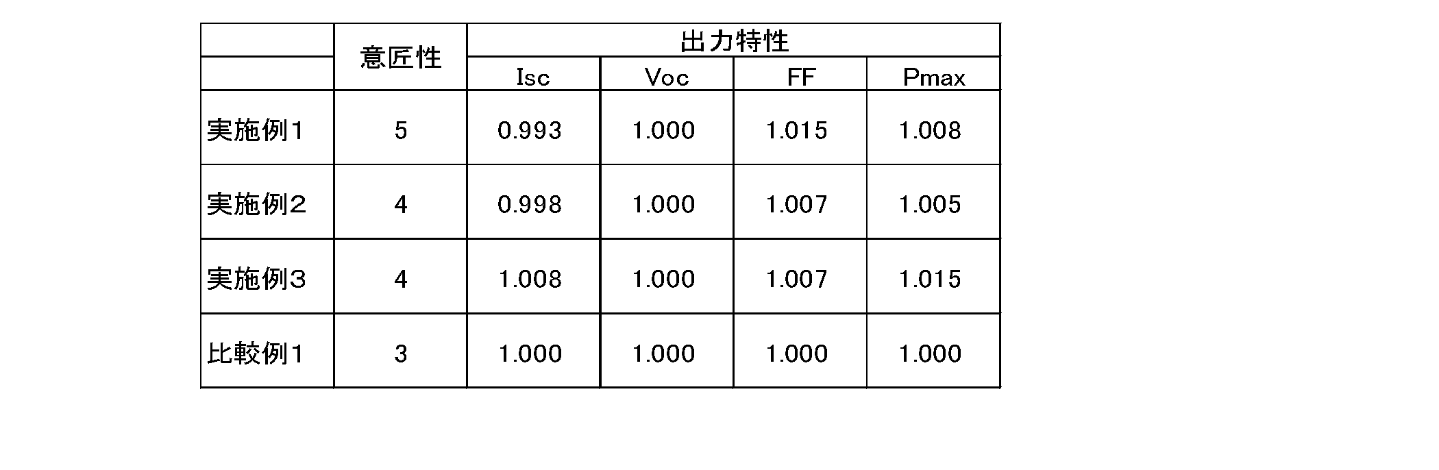
以上のように作製した実施例1、2、3、および比較例1の太陽電池モジュールの受光面を目視で観察し、黒色度を5段階で評価した。評価結果を表2に示す。なお、5が最も意匠性が優れたものとする。
以上のように作製した実施例1、2、3、および比較例1の太陽電池モジュールの受光面を目視で観察し、黒色度を5段階で評価した。評価結果を表2に示す。なお、5が最も意匠性が優れたものとする。
実施例1では、比較例1と比較して、太陽電池セルの縁部の意匠性が向上したことが確認された。
なお、実施例2でも、比較例1と比較して、より黒く意匠性が向上したことが確認された。実施例3でも、裏面側に白色系材料を用いたにもかかわらず、比較例1より、黒く意匠性が向上した。
なお、実施例2でも、比較例1と比較して、より黒く意匠性が向上したことが確認された。実施例3でも、裏面側に白色系材料を用いたにもかかわらず、比較例1より、黒く意匠性が向上した。
(出力特性)
AM1.5のスペクトル分布を有するパルスソーラーシミュレーターを用いて、25℃の下で擬似太陽光を100mW/cm2のエネルギー密度で照射して、上記の実施例および比較例の太陽電池モジュールの性能特性(短絡電流Isc、開放電圧Voc、曲線因子FF、および最大出力電力Pmax)を測定した。測定結果を表2に示す。
表2では、比較例1の出力特性結果を基準(1.000)とし、各実施例の評価結果を比較する事により、出力の相関を評価した。
AM1.5のスペクトル分布を有するパルスソーラーシミュレーターを用いて、25℃の下で擬似太陽光を100mW/cm2のエネルギー密度で照射して、上記の実施例および比較例の太陽電池モジュールの性能特性(短絡電流Isc、開放電圧Voc、曲線因子FF、および最大出力電力Pmax)を測定した。測定結果を表2に示す。
表2では、比較例1の出力特性結果を基準(1.000)とし、各実施例の評価結果を比較する事により、出力の相関を評価した。
実施例1では、比較例1と比較して、出力が向上した。黒色系パターンが太陽電池セルの縁部を覆うことで、発電面積の減少によりIscは低下するが、半導体層、TCO層および反射防止層の膜厚が薄い領域を隠す、つまり発電効率が低い領域を隠すことで、FFが向上した。結果、出力は向上した。
実施例2でも、比較例1と比較して、出力が向上した。黒色系パターンは、太陽電池セル隙間に配置されるが、シミュレーターの擬似太陽光は様々な角度で入射されるため、太陽電池セル縁部をわずかに覆う。そのため、発電面積の減少によりIscは低下するが、発電効率の低い領域が隠されるため、出力は向上する。なお、太陽電池セルの最縁部はより発電効率が低い領域のため、FF向上率は高くなった。
実施例3では、比較例1と比較して、出力が向上した。実施例2と同様に、Isc向上、FF向上のほかに、セルを透過した太陽光が、裏面側白色系材にて反射され、太陽電池セルに再入射されるため、Iscがさらに向上し、出力も向上した。

1 太陽電池セル
2 太陽電池ストリング
3 受光側保護部材
4 裏側保護部材
5 受光側封止材
6 裏側封止材
6a 裏側封止材の一部
7 第1受光側パターン
8 第2受光側パターン
9 裏側パターン
100 太陽電池モジュール
2 太陽電池ストリング
3 受光側保護部材
4 裏側保護部材
5 受光側封止材
6 裏側封止材
6a 裏側封止材の一部
7 第1受光側パターン
8 第2受光側パターン
9 裏側パターン
100 太陽電池モジュール
Claims (10)
- 複数の太陽電池セルを備える太陽電池モジュール、または複数の太陽電池セルをシングリング方式を用いて電気的に接続する太陽電池ストリングを複数備える太陽電池モジュールであって、
複数の前記太陽電池セルまたは前記太陽電池ストリングの受光面側を保護する受光側保護部材と、
複数の前記太陽電池セルまたは前記太陽電池ストリングの前記受光面側と反対の裏面側を保護する裏側保護部材と、
複数の前記太陽電池セルまたは前記太陽電池ストリングと前記受光側保護部材との間に配置され、複数の前記太陽電池セルまたは前記太陽電池ストリングを封止する受光側封止材と、
複数の前記太陽電池セルまたは前記太陽電池ストリングと前記裏側保護部材との間に配置され、複数の前記太陽電池セルまたは前記太陽電池ストリングを封止する裏側封止材と、
を備え、
前記受光側保護部材には、複数の前記太陽電池セルの間の隙間または複数の前記太陽電池ストリングの間の隙間に重畳する第1受光側パターンが形成されており、
前記第1受光側パターンは、前記太陽電池セルの受光面と同色または同系色である、
太陽電池モジュール。 - 前記第1受光側パターンは、黒色または黒色系である、請求項1に記載の太陽電池モジュール。
- 前記第1受光側パターンは、複数の前記太陽電池セルの縁部または複数の前記太陽電池ストリングの縁部を覆う、請求項1または2に記載の太陽電池モジュール。
- 前記裏側保護部材には、その表面の一部または全部を覆う裏側パターンが形成されており、
前記裏側パターンは、赤外光に対して反射特性を有する色である、
請求項1~3のいずれか1項に記載の太陽電池モジュール。 - 前記裏側パターンは、白色または白色系、または赤黒色または赤黒色系である、請求項4に記載の太陽電池モジュール。
- 前記裏側封止材の少なくとも前記裏側保護部材の側の一部は、赤外光に対して反射特性を有する材料を含む、請求項1~3のいずれか1項に記載の太陽電池モジュール。
- 前記裏側封止材の少なくとも前記裏側保護部材の側の一部は、白色または白色系、または赤黒色または赤黒色系の材料を含む、請求項6に記載の太陽電池モジュール。
- 前記第1受光側パターンは、前記受光側保護部材の前記受光側封止材の側に形成されている、請求項1~7のいずれか1項に記載の太陽電池モジュール。
- 前記受光側保護部材の前記第1受光側パターンの前記受光側封止材の側には、第2受光側パターンが形成されており、
前記第2受光側パターンは、赤外光に対して反射特性を有する色である、
請求項1~8のいずれか1項に記載の太陽電池モジュール。 - 前記第2受光側パターンは、白色または白色系、または赤黒色または赤黒色系である、請求項9に記載の太陽電池モジュール。
Priority Applications (2)
| Application Number | Priority Date | Filing Date | Title |
|---|---|---|---|
| CN201980068519.4A CN112868106B (zh) | 2018-12-12 | 2019-11-06 | 太阳能电池模块 |
| JP2020559819A JPWO2020121693A1 (ja) | 2018-12-12 | 2019-11-06 | 太陽電池モジュール |
Applications Claiming Priority (2)
| Application Number | Priority Date | Filing Date | Title |
|---|---|---|---|
| JP2018-232943 | 2018-12-12 | ||
| JP2018232943 | 2018-12-12 |
Publications (1)
| Publication Number | Publication Date |
|---|---|
| WO2020121693A1 true WO2020121693A1 (ja) | 2020-06-18 |
Family
ID=71076331
Family Applications (1)
| Application Number | Title | Priority Date | Filing Date |
|---|---|---|---|
| PCT/JP2019/043497 WO2020121693A1 (ja) | 2018-12-12 | 2019-11-06 | 太陽電池モジュール |
Country Status (3)
| Country | Link |
|---|---|
| JP (1) | JPWO2020121693A1 (ja) |
| CN (1) | CN112868106B (ja) |
| WO (1) | WO2020121693A1 (ja) |
Citations (9)
| Publication number | Priority date | Publication date | Assignee | Title |
|---|---|---|---|---|
| JPH11307795A (ja) * | 1998-04-22 | 1999-11-05 | Sanyo Electric Co Ltd | 太陽電池モジュール |
| JP2012033546A (ja) * | 2010-07-28 | 2012-02-16 | Sharp Corp | 太陽電池モジュール |
| JP2012114331A (ja) * | 2010-11-26 | 2012-06-14 | Koito Mfg Co Ltd | 太陽電池モジュール |
| JP2014135318A (ja) * | 2013-01-08 | 2014-07-24 | Mitsubishi Electric Corp | 太陽電池モジュール及びその製造方法 |
| JP2014207305A (ja) * | 2013-04-12 | 2014-10-30 | 三洋電機株式会社 | 太陽電池モジュール |
| US20170148942A1 (en) * | 2014-07-11 | 2017-05-25 | Stichting Energieonderzoek Centrum Nederland | Solar panel and method of manufacturing such a solar panel |
| WO2017143190A1 (en) * | 2016-02-19 | 2017-08-24 | Sunedison, Inc. | Connection cells for photovoltaic modules |
| US20170256661A1 (en) * | 2016-03-02 | 2017-09-07 | Solarcity Corporation | Method of manufacturing photovoltaic panels with various geometrical shapes |
| US20180198011A1 (en) * | 2017-01-06 | 2018-07-12 | Lg Electronics Inc. | Solar cell panel |
Family Cites Families (2)
| Publication number | Priority date | Publication date | Assignee | Title |
|---|---|---|---|---|
| WO2007071703A1 (en) * | 2005-12-22 | 2007-06-28 | Shell Erneuerbare Energien Gmbh | Photovoltaic device and method for encapsulating |
| CN103441166B (zh) * | 2013-07-10 | 2015-09-09 | 友达光电股份有限公司 | 太阳能电池模块 |
-
2019
- 2019-11-06 CN CN201980068519.4A patent/CN112868106B/zh active Active
- 2019-11-06 JP JP2020559819A patent/JPWO2020121693A1/ja active Pending
- 2019-11-06 WO PCT/JP2019/043497 patent/WO2020121693A1/ja active Application Filing
Patent Citations (9)
| Publication number | Priority date | Publication date | Assignee | Title |
|---|---|---|---|---|
| JPH11307795A (ja) * | 1998-04-22 | 1999-11-05 | Sanyo Electric Co Ltd | 太陽電池モジュール |
| JP2012033546A (ja) * | 2010-07-28 | 2012-02-16 | Sharp Corp | 太陽電池モジュール |
| JP2012114331A (ja) * | 2010-11-26 | 2012-06-14 | Koito Mfg Co Ltd | 太陽電池モジュール |
| JP2014135318A (ja) * | 2013-01-08 | 2014-07-24 | Mitsubishi Electric Corp | 太陽電池モジュール及びその製造方法 |
| JP2014207305A (ja) * | 2013-04-12 | 2014-10-30 | 三洋電機株式会社 | 太陽電池モジュール |
| US20170148942A1 (en) * | 2014-07-11 | 2017-05-25 | Stichting Energieonderzoek Centrum Nederland | Solar panel and method of manufacturing such a solar panel |
| WO2017143190A1 (en) * | 2016-02-19 | 2017-08-24 | Sunedison, Inc. | Connection cells for photovoltaic modules |
| US20170256661A1 (en) * | 2016-03-02 | 2017-09-07 | Solarcity Corporation | Method of manufacturing photovoltaic panels with various geometrical shapes |
| US20180198011A1 (en) * | 2017-01-06 | 2018-07-12 | Lg Electronics Inc. | Solar cell panel |
Also Published As
| Publication number | Publication date |
|---|---|
| CN112868106A (zh) | 2021-05-28 |
| CN112868106B (zh) | 2024-03-08 |
| JPWO2020121693A1 (ja) | 2021-10-21 |
Similar Documents
| Publication | Publication Date | Title |
|---|---|---|
| EP1763088B1 (en) | Photovoltaic module | |
| US20130206210A1 (en) | Solar battery module, photovoltaic apparatus, and manufacturing method of solar battery module | |
| JP6788657B2 (ja) | 太陽電池モジュール | |
| EP2398063A1 (en) | Solar battery module | |
| JPWO2019146366A1 (ja) | 太陽電池モジュール | |
| TWI539613B (zh) | 高功率太陽能電池模組 | |
| US9502588B2 (en) | Solar cell module | |
| JP6745089B2 (ja) | 太陽電池モジュール | |
| JP2009032779A (ja) | 薄膜太陽電池モジュール | |
| WO2020121693A1 (ja) | 太陽電池モジュール | |
| WO2020129501A1 (ja) | 太陽電池モジュール集積デバイス | |
| JP6995828B2 (ja) | 太陽電池モジュール | |
| JP7349979B2 (ja) | 太陽電池モジュール | |
| US9082900B2 (en) | Photovoltaic module and manufacturing method thereof | |
| US20110272025A1 (en) | Photovoltaic module | |
| KR20140121915A (ko) | 양면 수광형 태양전지 모듈 | |
| WO2023037885A1 (ja) | 太陽電池デバイスおよび太陽電池モジュール | |
| JP2019169611A (ja) | 太陽電池モジュール | |
| WO2023127382A1 (ja) | 太陽電池デバイスおよび太陽電池モジュール | |
| JP2010232701A (ja) | 太陽電池モジュール | |
| CN110998866B (zh) | 太阳能电池模块 | |
| JP2007208286A (ja) | 太陽電池モジュール | |
| JP2022142573A (ja) | 太陽電池モジュール | |
| TWM517475U (zh) | 高功率太陽能電池模組 | |
| JP6776118B2 (ja) | 太陽電池モジュール |
Legal Events
| Date | Code | Title | Description |
|---|---|---|---|
| 121 | Ep: the epo has been informed by wipo that ep was designated in this application |
Ref document number: 19895429 Country of ref document: EP Kind code of ref document: A1 |
|
| ENP | Entry into the national phase |
Ref document number: 2020559819 Country of ref document: JP Kind code of ref document: A |
|
| NENP | Non-entry into the national phase |
Ref country code: DE |
|
| 122 | Ep: pct application non-entry in european phase |
Ref document number: 19895429 Country of ref document: EP Kind code of ref document: A1 |