WO2020121658A1 - 受電装置、受電装置の制御方法及びプログラム - Google Patents
受電装置、受電装置の制御方法及びプログラム Download PDFInfo
- Publication number
- WO2020121658A1 WO2020121658A1 PCT/JP2019/041915 JP2019041915W WO2020121658A1 WO 2020121658 A1 WO2020121658 A1 WO 2020121658A1 JP 2019041915 W JP2019041915 W JP 2019041915W WO 2020121658 A1 WO2020121658 A1 WO 2020121658A1
- Authority
- WO
- WIPO (PCT)
- Prior art keywords
- communication
- power
- power transmission
- control
- power receiving
- Prior art date
Links
- 238000000034 method Methods 0.000 title claims description 77
- 238000004891 communication Methods 0.000 claims abstract description 315
- 230000005540 biological transmission Effects 0.000 claims abstract description 235
- 230000008569 process Effects 0.000 description 52
- 238000012545 processing Methods 0.000 description 26
- 230000007704 transition Effects 0.000 description 14
- 230000004044 response Effects 0.000 description 13
- 239000003999 initiator Substances 0.000 description 12
- 230000006870 function Effects 0.000 description 9
- 238000010586 diagram Methods 0.000 description 6
- 230000002093 peripheral effect Effects 0.000 description 4
- 230000000694 effects Effects 0.000 description 3
- 238000012546 transfer Methods 0.000 description 3
- 238000004590 computer program Methods 0.000 description 2
- 230000020169 heat generation Effects 0.000 description 2
- 230000007246 mechanism Effects 0.000 description 2
- 230000004048 modification Effects 0.000 description 2
- 238000012986 modification Methods 0.000 description 2
- 238000009774 resonance method Methods 0.000 description 2
- 230000002457 bidirectional effect Effects 0.000 description 1
- 230000008878 coupling Effects 0.000 description 1
- 238000010168 coupling process Methods 0.000 description 1
- 238000005859 coupling reaction Methods 0.000 description 1
- 238000001514 detection method Methods 0.000 description 1
- 238000011161 development Methods 0.000 description 1
- 230000005684 electric field Effects 0.000 description 1
- 230000005674 electromagnetic induction Effects 0.000 description 1
- 238000005516 engineering process Methods 0.000 description 1
- 230000005669 field effect Effects 0.000 description 1
- 238000003384 imaging method Methods 0.000 description 1
- 230000010365 information processing Effects 0.000 description 1
- 230000002265 prevention Effects 0.000 description 1
- 230000002250 progressing effect Effects 0.000 description 1
Images

Classifications
-
- H04B5/79—
-
- H—ELECTRICITY
- H02—GENERATION; CONVERSION OR DISTRIBUTION OF ELECTRIC POWER
- H02J—CIRCUIT ARRANGEMENTS OR SYSTEMS FOR SUPPLYING OR DISTRIBUTING ELECTRIC POWER; SYSTEMS FOR STORING ELECTRIC ENERGY
- H02J50/00—Circuit arrangements or systems for wireless supply or distribution of electric power
- H02J50/10—Circuit arrangements or systems for wireless supply or distribution of electric power using inductive coupling
-
- H—ELECTRICITY
- H02—GENERATION; CONVERSION OR DISTRIBUTION OF ELECTRIC POWER
- H02J—CIRCUIT ARRANGEMENTS OR SYSTEMS FOR SUPPLYING OR DISTRIBUTING ELECTRIC POWER; SYSTEMS FOR STORING ELECTRIC ENERGY
- H02J50/00—Circuit arrangements or systems for wireless supply or distribution of electric power
- H02J50/20—Circuit arrangements or systems for wireless supply or distribution of electric power using microwaves or radio frequency waves
- H02J50/23—Circuit arrangements or systems for wireless supply or distribution of electric power using microwaves or radio frequency waves characterised by the type of transmitting antennas, e.g. directional array antennas or Yagi antennas
-
- H—ELECTRICITY
- H02—GENERATION; CONVERSION OR DISTRIBUTION OF ELECTRIC POWER
- H02J—CIRCUIT ARRANGEMENTS OR SYSTEMS FOR SUPPLYING OR DISTRIBUTING ELECTRIC POWER; SYSTEMS FOR STORING ELECTRIC ENERGY
- H02J50/00—Circuit arrangements or systems for wireless supply or distribution of electric power
- H02J50/80—Circuit arrangements or systems for wireless supply or distribution of electric power involving the exchange of data, concerning supply or distribution of electric power, between transmitting devices and receiving devices
-
- H—ELECTRICITY
- H02—GENERATION; CONVERSION OR DISTRIBUTION OF ELECTRIC POWER
- H02J—CIRCUIT ARRANGEMENTS OR SYSTEMS FOR SUPPLYING OR DISTRIBUTING ELECTRIC POWER; SYSTEMS FOR STORING ELECTRIC ENERGY
- H02J7/00—Circuit arrangements for charging or depolarising batteries or for supplying loads from batteries
- H02J7/00032—Circuit arrangements for charging or depolarising batteries or for supplying loads from batteries characterised by data exchange
- H02J7/00034—Charger exchanging data with an electronic device, i.e. telephone, whose internal battery is under charge
-
- H04B5/24—
-
- H04B5/72—
-
- H—ELECTRICITY
- H04—ELECTRIC COMMUNICATION TECHNIQUE
- H04W—WIRELESS COMMUNICATION NETWORKS
- H04W76/00—Connection management
- H04W76/10—Connection setup
- H04W76/14—Direct-mode setup
-
- H—ELECTRICITY
- H04—ELECTRIC COMMUNICATION TECHNIQUE
- H04W—WIRELESS COMMUNICATION NETWORKS
- H04W4/00—Services specially adapted for wireless communication networks; Facilities therefor
- H04W4/80—Services using short range communication, e.g. near-field communication [NFC], radio-frequency identification [RFID] or low energy communication
Definitions
- the present invention relates to a power receiving device, a power receiving device control method, and a program.
- Patent Document 1 discloses a power transmission device and a power reception device that comply with a standard (WPC standard) established by the wireless power consortium (WPC), which is a standardization group for contactless charging standards.
- WPC wireless power consortium
- the power transmitting device and the power receiving device exchange the control information necessary for power transmission by communication in which the control information is superimposed on the power to be transmitted and received.
- Patent Document 2 a control signal implemented between a power transmitting device and a power receiving device for controlling transmitted power is transmitted to a communication unit through a different coil (or antenna) at a frequency different from those of the power transmitting unit and the power receiving unit.
- a technique for communicating by using the communication is disclosed.
- Control communication in the wireless power transmission system includes packets with a small amount of data and packets with a large amount of data.
- those packets are not transmitted/received by properly using the plurality of communication units.
- the present invention has been made in view of the above problems, and provides a technique capable of suitably controlling a plurality of communication units during wireless power transmission.
- a power receiving device that achieves the above object, Power receiving means for wirelessly receiving power from the power transmitting device; First communication means for performing control communication of wireless power transmission with the power transmission device, Second communication means for performing control communication of wireless power transmission with the power transmission device by a method different from the first communication means, When the control communication using the first communication means is switched to the control communication using the second communication means, the power transmission from the power transmission device is continued via the first communication means.
- Control means for performing predetermined communication with the power transmission device It is characterized by including.
- FIG. 6 is an operation sequence diagram of the wireless power transmission system according to the embodiment. 6 is a flowchart showing a procedure of processing performed by the power receiving device according to the embodiment. 6 is a flowchart showing a procedure of processing performed by the power receiving device according to the embodiment. 6 is a flowchart showing a procedure of processing performed by the power transmission device according to the embodiment. 6 is a flowchart showing a procedure of processing performed by the power transmission device according to the embodiment. 6 is a flowchart showing a procedure of processing performed by the power transmission device according to the embodiment. 6 is a flowchart showing a procedure of processing relating to prevention of power transmission stop performed by the power transmission device according to the embodiment.
- FIG. 1 is a block diagram showing a configuration example of a power transmission device applicable to a wireless power transmission system according to an embodiment. It is assumed that the power transmission device 100 complies with the WPC standard and further complies with the device authentication protocol. In the present embodiment, the power transmitting device and the power receiving device are described as compliant with the WPC standard, but the present invention is not limited to this and other wireless power transmission standards may be used.
- the power transmission device 100 includes a control unit 101, a power supply unit 102, a power transmission unit 103, a first communication unit 104, a power transmission coil 105, a second communication unit 106, a memory 107, and an authentication unit 108.
- the control unit 101 controls the entire power transmission device 100.
- An example of the control unit 101 is a CPU (Central Processing Unit).
- the power supply unit 102 supplies power for operating at least the control unit 101 and the power transmission unit 103.
- Power transmission unit 103 generates an AC voltage and an AC current to be transmitted to power reception device 200, which will be described later with reference to FIG. 2, via power transmission coil 105.
- the power transmission unit 103 converts the DC voltage supplied from the power supply unit 102 into an AC voltage by a half-bridge or full-bridge switching circuit using a FET (Field Effect Transistor).
- the power transmission unit 103 includes a gate driver that controls ON/OFF of the FET. Further, it is assumed that the power transmission unit 103 has a power supply capability of outputting, for example, 15 watts of power to the charging unit of the power receiving device 200 compatible with the WPC standard.
- the first communication unit 104 performs control communication of wireless power transmission based on the WPC standard with the communication unit of the power receiving device 200 (first communication unit 204 in FIG. 2).
- the communication performed by the first communication unit 104 is communication in which the AC voltage or current generated by the power transmission unit 103 is modulated and a signal used for wireless power transmission is superimposed.
- first communication communication performed between the first communication unit 104 and the communication unit of the power receiving device 200 (first communication unit 204 in FIG. 2) is referred to as first communication.
- the second communication unit 106 performs control communication of wireless power transmission based on the WPC standard with the communication unit of the power receiving device 200 (the second communication unit 202 of FIG. 2).
- the communication by the second communication unit 106 is a communication using a frequency different from the frequency of the power transmission unit 103, and uses an antenna (not shown) different from the power transmission coil 105.
- the second communication unit 106 will be described as operating as a Bluetooth Low Energy (BLE) peripheral. However, it may be BLE Central, Near Field Communication (NFC), or WiFi.
- BLE Bluetooth Low Energy
- NFC Near Field Communication
- the communication performed between the second communication unit 106 and the communication unit of the power receiving device 200 is referred to as second communication.
- the second communication unit 106 is controlled by the control unit 101, but is configured to be controlled by the control unit of another device (camera, smartphone, tablet PC, laptop) (not shown) including the power transmission device 100. May be.
- the memory 107 stores the states of the power transmitting device 100 and the power receiving device 200.
- a computer program for operating the power transmission device 100 is stored.
- the authentication unit 108 executes a device authentication protocol with the power receiving device 200 via the first communication unit 104 or the second communication unit 106.
- control unit 101 the power supply unit 102, the power transmission unit 103, the first communication unit 104, the memory 107, the second communication unit 106 is described as a separate body, but any of these A plurality may be mounted in the same chip.
- FIG. 2 is a block diagram showing a configuration example of a power receiving device applicable to the wireless power transmission system according to the embodiment. It is assumed that the power receiving device 200 complies with the WPC standard, includes the functions described in the WPC standard v1.2.2, and additionally supports the device authentication protocol.
- the power receiving device 200 includes a control unit 201, a second communication unit 202, a power receiving unit 203, a first communication unit 204, a power transmission coil 205, a charging unit 206, a battery 207, a memory 208, and an authentication unit 209.
- the control unit 201 controls the entire power receiving device 200.
- An example of the control unit 201 is a CPU.
- Power reception unit 203 converts the AC voltage and AC current received from power transmission coil 105 via power reception coil 205 into a DC voltage and a DC current for operating control unit 201, charging unit 206 and the like. It is assumed that the power reception unit 203 has a power supply capability of supplying power for the charging unit 206 to charge the battery 207 and outputting 15 watts of power to the charging unit 206.
- the first communication unit 204 performs control communication of wireless power transmission based on the WPC standard with the first communication unit 104 of the power transmission device 100. This control communication is communication performed by load-modulating the electromagnetic wave received by the power receiving coil 205.
- the second communication unit 202 performs control communication of wireless power transmission based on the WPC standard with the second communication unit 106 of the power transmission device 100.
- the communication by the second communication unit 202 is a communication using a frequency different from the frequency of the power transmission unit 103 of the power transmission device 100, and uses an antenna (not shown) different from the power transmission coil 105.
- the second communication unit 202 will be described as being compatible with BLE central. However, it may be a BLE peripheral, NFC or WiFi. In this embodiment, it is assumed that the communication by the second communication unit 202 can be performed at a higher speed than the communication by the first communication unit 204.
- the second communication unit 202 is controlled by the control unit 201, but is configured to be controlled by the control unit of another device (camera, smartphone, tablet PC, laptop) (not shown) including the power receiving device 200. May be.
- the memory 208 stores the states of the power transmitting device 100 and the power receiving device 200.
- a computer program for operating the power receiving device 200 is stored.
- the authentication unit 209 executes a device authentication protocol with the power transmission device 100 via the first communication unit 204 or the second communication unit 202.
- FIG. 3 is a sequence diagram of a power transmitting device and a power receiving device applicable to the wireless power transmission system according to the embodiment.
- Analog Ping is a signal of minute electric power for detecting an object existing in the vicinity of the power transmission coil 105.
- the power transmitting apparatus 100 is transmitting the analog ping, the power transmitting apparatus 100 is in the selection phase.
- the power transmission device 100 detects a voltage value or a current value of the power transmission coil 105 when transmitting the analog ping. Then, when the voltage is below a certain threshold value or the current value is above a certain threshold value, it is determined that an object exists around the power transmission coil 105, and the power transmission apparatus 100 transitions to the Ping phase.
- the power transmission device 100 transmits a Digital Ping, which has higher power than the Analog Ping (F301). It is assumed that the size of the Digital Ping is sufficient to activate at least the power receiving device 200 and the control unit 201 existing near the power transmission coil 105.
- the control unit 201 of the power receiving device 200 is activated by the power (Digital Ping) received via the power receiving coil 205.
- the magnitude of the received voltage is notified to the power transmitting device 100 (F302), and the process transitions to Identification & Configuration (hereinafter referred to as I&C phase).
- the notification of the received voltage is performed by the first communication via the first communication unit 204.
- the power transmission device 100 When the power transmission device 100 receives the power reception voltage notification from the power reception device 200, the power transmission device 100 transitions to the I&C phase. Next, the power receiving device 200 transmits an ID packet including a manufacturer code indicating the manufacturer of the device itself and device identification information to the power transmitting device 100 (F303). Further, the power transmission device 100 transmits a Configuration Packet including a standard version with which the power transmission device 100 complies to the power transmission device 100 (F304).
- the power transmitting apparatus 100 receives the Configuration Packet from the power receiving apparatus 200 and determines whether the standard version supported by the power receiving apparatus 200 is, for example, v1.2.2 or higher.
- the standard version is v1.2.2 or later
- ACK indicating that the information included in the Configuration Packet has been licensed is transmitted to the power receiving device 200 (F305). Then, it transits to the Negotiation phase (F319).
- the power receiving device 200 receives the ACK (F305)
- the power receiving device 200 transits to the Negotiation phase (F319).
- the predetermined processing (F306 to F318, F323, F324) peculiar to this embodiment will be described later.
- the power transmitting device 100 and the power receiving device 200 perform negotiations to determine the Guaranteed Power (hereinafter, referred to as GP) that indicates the amount of power that the power receiving device 200 can receive without fail.
- GP Guaranteed Power
- the power receiving device 200 notifies the power transmitting device 100 of a value that is a GP candidate.
- the power transmission device 100 permits or rejects the notification. Since the power receiving device 200 has a power supply capability of outputting 15 watts of power to the charging unit 206, a maximum of 15 watts can be notified as a candidate for the GP value.
- the power transmission device 100 can permit a maximum value of 15 watts as the GP value.
- the power transmitting device 100 and the power receiving device 200 transit to the Calibration phase (F320).
- the calibration phase (F320) although not described in detail, the power transmission device 10 determines parameters necessary for the foreign matter detection function that detects the presence of an object other than the power reception device 200 in the vicinity of the power transmission coil 105.
- the power receiving device 100 also performs a process of supplying power from the power receiving unit 203 to the charging unit 206 that is a load. After that, the power transmitting apparatus 100 and the power receiving apparatus 200 transition to the Power Transfer phase (F321), and the power receiving apparatus 200 charges the battery 207.
- the device authentication is a process of confirming the validity of each other between the power transmitting device 100 and the power receiving device 200, and is a bidirectional process. Specifically, the power transmitting apparatus 100 may check the legitimacy of the power receiving apparatus 200, or the power receiving apparatus 200 may check the legitimacy of the power transmitting apparatus 100. Then, the magnitude of power to be transmitted and received is determined according to the result of device authentication.
- the power transmitting apparatus 100 transmits power to a power receiving apparatus that has not been confirmed to be valid with a smaller amount of power than the power transmitted to the power receiving apparatus that has been validated. Therefore, the power transmitting apparatus 100 allows only a small GP in the Negotiation phase with respect to the power receiving apparatus whose legitimacy cannot be confirmed as compared with the power receiving apparatus whose legitimacy has been confirmed, and is a GP which can be supplied by itself. The maximum value of 15 watts is not allowed.
- the power receiving device that could not be verified as legitimate may be a poor power receiving device and may generate excessive heat compared to a valid power receiving device, but this should prevent excessive heat generation. You can
- the power receiving apparatus 200 requests the power transmitting apparatus, which has not been confirmed to be valid, to have a smaller GP than the electric power received from the power transmitting apparatus, which has been able to be validated.
- the power receiving device 200 does not request the maximum value of its own GP, 15 watts, to the power transmitting device whose validity cannot be confirmed in the Negotiation phase.
- a power transmission device that could not be verified as legitimate may be a poor power transmission device and may overheat compared to a legitimate power transmission device, but this prevents excessive heat generation. can do.
- device authentication is performed before the negotiation phase. This is because the result of device authentication affects the size of the GP negotiated in the negotiation phase. If the device authentication is performed after the GP is determined in the Negotiation phase, it is possible that transition to the Negotiation phase again based on the result of the device authentication and unnecessary processing such as redoing the GP negotiations will occur. is there.
- the WPC standard has a mechanism for stopping power transmission when the power transmitting apparatus 100 cannot detect the power receiving apparatus 200.
- the power transmitting device 100 can stop power transmission. Therefore, it is possible to prevent the power receiving device 200 from continuously emitting unnecessary radio waves even though the power receiving device 200 is not in the power transmission range.
- the first end of the next packet is received within a predetermined time (25 ms) after the power transmission device 100 receives the rear end of the packet transmitted by the first communication unit 204 of the power reception device 200. If not, the power transmission device 100 stops power transmission.
- the negotiation phase when the power transmitting apparatus 100 does not receive the next packet within a predetermined time (250 ms) after the power transmitting apparatus 100 transmits a response to the packet transmitted by the first communication unit 204 of the power receiving apparatus 200, The power transmission device 100 stops power transmission.
- the power transmission device 100 stops power transmission. In this way, the power transmission device 100 has a function of stopping power transmission due to a timeout.
- the device authentication (control communication) is performed in the second communication when the I&C phase ends and the device enters the negotiation phase, the result of the device authentication in which the GP negotiation is performed in the second communication for the reason described above. Based on. Therefore, there is no packet to be transmitted by the power receiving device in the first communication. Then, as described above, the power transmission device does not receive the packet from the power reception device in the first communication for the predetermined time, and stops the power transmission. In addition, since the second communication is likely to be retransmitted due to interference with other wireless communication, the time during which the first communication is not performed may be longer.
- the power receiving device transmits a packet to the power transmission device in the first communication even while performing device authentication with the power transmission device in the second communication. This makes it possible to prevent the power transmission device from stopping power transmission.
- the power transmission device 100 transmits an Analog Ping (F300), and if it determines that an object exists near the power transmission coil, transmits the Digital Ping (F301).
- the control unit 201 is activated. Then, the power reception voltage of Digital Ping is notified to the power transmission device 200 (F302), and the process shifts to the I&C phase.
- the power receiving device 200 transmits the ID Packet (F303) and the Configuration Packet to the power transmitting device 100 via the first communication unit 104 (F304).
- the power transmission device 200 receives the Configuration Packet, it transmits ACK (F305).
- the power receiving apparatus 200 Upon receiving the ACK (F305), the power receiving apparatus 200 transmits OOBReq (F306).
- the power receiving device 200 supports device authentication, and also supports device authentication using BLE.
- the power transmission device 100 also supports device authentication, and further supports device authentication using BLE. Therefore, the power transmitting apparatus 100 transmits ACK that permits the device authentication by BLE (F307).
- the power receiving device 200 When the power receiving device 200 receives the ACK (F307), it starts transmitting the IDLE via the first communication unit 104 (F308).
- the power transmission device 100 transmits ACK to IDLE (F323).
- the power receiving apparatus 200 may transmit the EPT that instructs the power transmitting apparatus 100 to stop power transmission.
- the power receiving apparatus 200 may also transmit the EPT when the power receiving apparatus 200 receives another packet that is not an ACK for IDLE, such as NAK or ND (Not Defined).
- An ND packet is a response packet transmitted by the power transmission device 100 when the power transmission device 100 cannot understand the packet transmitted by the power reception device 200.
- the power transmitting apparatus 100 has transmitted the ACK to the power receiving apparatus 200 in response to the OOBReq received from the power receiving apparatus 200 (F307), the power transmitting apparatus 100 transmits the IDLE to prevent the power transmission from being stopped due to the timeout. 100 should be understandable. Nevertheless, when the power receiving device 200 receives NAK or ND from the power transmitting device 100 (F323), the power receiving device 200 interprets that the power transmitting device 100 has failed, and can stop power transmission by transmitting the EPT.
- the power transmission device 100 transmits ADV via the second communication unit 106 (F309). Then, the power receiving device 200 transmits CONNECT via the second communication unit 202 (F311). After that, the power receiving device 200 transmits AuthReq (F312), and after receiving ACK from the power transmitting device 100 (F313), the power receiving device 200 performs the Auth process in which the power receiving device 200 operates as an initiator (F314).
- the power receiving device 200 transmits IDLE (for example, periodically) before a certain time has elapsed (F310, F324). Then, the power transmission device 100 responds to the IDLE with ACK (not shown). Subsequently, the power transmitting apparatus 100 transmits AuthReq (F315), receives an ACK from the power receiving apparatus 200 (F316), and then executes the Auth process in which the power transmitting apparatus 100 itself operates as an initiator (F317).
- IDLE for example, periodically
- ACK not shown
- the power transmitting apparatus 100 transmits AuthReq (F315), receives an ACK from the power receiving apparatus 200 (F316), and then executes the Auth process in which the power transmitting apparatus 100 itself operates as an initiator (F317).
- the power receiving device 200 transmits TERMINATE to the power transmitting device 100 (F318) and ends the BLE communication. Since the Auth process is completed, the power transmitting device 100 and the power receiving device 200 perform GP Negotiation (F319), and transit to the Calibration phase (F320) and then to the PT phase (F321).
- the packet type of which is Packet Type is Guaranteed Power
- the power transmitting device 100 and the power receiving device 200 decide It is stipulated in the WPC standard that packets are transmitted and received at specified timings. Therefore, thereafter, the power transmission device 100 will not stop power transmission due to a timeout. Therefore, the power receiving device 200 stops the transmission of IDLE that was transmitted for the purpose of preventing the timeout.
- the power receiving device can prevent the power transmitting device from stopping the power transmission by transmitting the IDLE in the first communication. Furthermore, after the GP negotiation in which there is a packet to be transmitted in the first communication, the transmission of the IDLE is stopped, so that the unnecessary packet transmission is stopped and the processing can be reduced.
- the second communication unit 106 cannot be used while the power transmission device 100 is performing the second communication.
- the power transmitting apparatus 100 may be configured to respond to the IDLE with NAK when it determines that the second communication unit 106 cannot be used for the second communication.
- the power receiving device 200 Upon receiving the NAK, the power receiving device 200 switches the control communication performed in the second communication to the first communication. Specifically, if the TERMINATE is not received after receiving the NAK, the power receiving device 200 transmits the TERMINATE. Then, the control communication performed in the second communication is performed in the first communication. As a matter of course, the power receiving apparatus 200 does not need to transmit the IDLE and stops the transmission because there is a packet to be transmitted in the first communication at the time of switching to the first communication. Thereby, even when the second communication cannot be used, the communication with the power transmission device 100 can be continued.
- the battery (not shown) of the power receiving device 200 supplies electric power for operating the second communication unit 202 of the power receiving device 200.
- the power receiving device 200 may store “0” in the BLE bit of Configuration Packet.
- the power receiving device 200 stores “0” in the BLE bit of Configuration Packet. You may do it. As a result, it is possible to avoid the occurrence of a problem in which the power transmitting apparatus 100 transmits ADV even though the power receiving apparatus 200 cannot use BLE for the second communication.
- the power receiving device 200 transmits the ID Packet and the Configuration Packet to the power transmitting device 100.
- the power receiving device 200 notifies the power transmitting device 100 that the Configuration Packet supports device authentication and that device authentication can be performed by the second communication using BLE.
- BLE Authentication bit
- Auth bit is a bit to show that it supports device authentication.
- BLE bit is a bit for indicating that device authentication can be performed by the second communication by BLE.
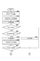
- the power receiving device 200 determines whether or not an ACK for the Configuration Packet has been received from the power transmitting device. According to the WPC standard v1.2.2, when the ACK is received for the Configuration Packet, the power receiving device 200 can recognize that the power transmitting device supports the Negotiation phase. When receiving the ACK, the power receiving apparatus 200 transitions to the Negotiation phase and proceeds to S404. On the other hand, if no ACK is received, the process proceeds to S418.
- the power receiving device 200 transmits, through the first communication unit 202, an Out OF Band Request (OOB Req) packet indicating that the second communication by BLE is requested.
- OOB Req Out OF Band Request
- the OOBReq packet is transmitted to confirm whether or not the power transmission device 100 is compatible with BLE as the second communication unit 104 and is compatible with device authentication using the second communication unit 104.
- OOB Req packet includes BLE bit, and if BLE bit is "1", it indicates that BLE is requested to be used as the second communication. Also, the OOB Req packet includes an Auth bit, and if the Auth bit is "1", it indicates that device authentication using the second communication is requested.
- the OOBReq packet may include an NFCbit that requests to use NFC as the type of second communication. If the NFC bit is "1", it indicates that NFC is requested to be used as the second communication. Similarly, it may include a WiFi bit that requests the use of WiFi as the second communication type. Furthermore, among General Request and Specific Request defined in the WPC standard, Reserved Packet or Proprietary Packet packet in which Packet type is not defined may be defined as OOB Req packet.
- the power receiving device 200 determines whether or not an ACK is received as a response of OOBReq from the power transmitting device 100.
- the power receiving device 200 receives an ACK as a response of OOBReq from the power transmitting device 100
- the power receiving device 200 is configured such that the power transmitting device 100 supports BLE as the second communication unit 104, and further uses the second communication unit 104. You can recognize that the device authentication is supported. If ACK is received, the process proceeds to S406. On the other hand, if the ACK is not received, the process proceeds to S420.
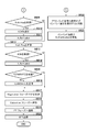
- the power receiving device 200 periodically transmits an IDLE to the power transmitting device 100 via the first communication unit 204 at a timing defined by the WPC standard from the transition to the Negotiation phase until the GP negotiation.
- IDLE corresponds to F308, F310, and F324 in FIG. 3, for example.
- the power receiving device 200 transmits the next IDLE.
- the IDLE packet is a packet that is periodically transmitted in order to prevent power transmission to the power transmission device 100 when the control communication is performed in the second communication.
- the power transmitting apparatus 100 that can understand OOB Req may send ACK as a response when receiving IDLE. Since the power transmission device 100 receives IDLE regularly, it does not stop power transmission due to timeout. Therefore, when the device authentication is performed in the second communication, it is possible to prevent the power transmission device from stopping the power transmission without receiving the packet in the first communication for a certain period of time.
- the IDLE transmitted by the power receiving device 200 is for the purpose of preventing the power transmitting device 100 from determining a time-out, and thus other packets may be used.
- other packets may be used.
- Reserved Packet or Proprietary Packet in which Packet Type is not defined may be used.
- the power receiving device 200 determines whether or not an Advertise Indication packet (hereinafter referred to as ADV) is received from the second communication unit 104 of the power transmitting device 100 within a fixed time after receiving the ACK in S405. .
- ADV is information transmitted by the BLE peripheral.
- the ADV stores Bluetooth Device Address (hereinafter referred to as BD address), which is individual identification information of the peripheral, and corresponding profile information (service information). If ADV is received within the fixed time, the process proceeds to S408. On the other hand, if ADV is not received within the fixed time, the process proceeds to S421.
- the power receiving apparatus 200 receives the BD address of the second communication unit 104 of the power transmitting apparatus 100 in advance in order to determine whether the ADV received by the power receiving apparatus 200 is the ADV transmitted by the power transmitting apparatus 100. You may keep it. Specifically, after receiving the ACK in S405, the power receiving apparatus 200 transmits, via the first communication unit 204, a packet defined by the WPC standard to the power transmitting apparatus 100 as a packet inquiring about the capability. Then, the power transmission device 100 may transmit a response in which the BD address is stored as the response of the packet to the power reception device 200 via the first communication unit 104. Also, a packet for inquiring the BD address may be newly allocated. For example, in General Request or Specific Request, Reserved Packet or Proprietary Packet packet for which Packet type is not defined may be assigned.
- the power receiving device 200 receives the BD address of the power transmitting device 100 and determines whether or not the ADV is received from the power transmitting device 100 by determining whether or not the BD address received via the second communication unit 202 matches. Can be determined.
- the power receiving device 200 transmits a CONNECT packet indicating that a BLE connection will be made to the power transmitting device 100 via the second communication unit 202.
- the power receiving device 200 transmits the AuthReq packet to the power transmitting device 100 via the second communication unit 202 after the BLE data can be transmitted/received to/from the power transmitting device 100.
- the AuthReq packet is a packet for indicating that device authentication for confirming the validity of the power transmission device 100 is requested.
- the AuthReq packet operates as an initiator whose role is to confirm the legitimacy of the destination (power transmitting device 100) of the packet source (power receiving device 200), and as a responder whose role is to confirm the legitimacy of the destination. Contains information that requires it to operate.
- the power receiving device 200 determines whether or not an ACK indicating permission for AuthReq is received from the power transmitting device 100. If an ACK indicating permission is received, the process proceeds to S411. On the other hand, if no ACK indicating permission is received, the process proceeds to S412.
- the power receiving device 200 implements Authentication, which is a device authentication protocol.
- Authentication processing (hereinafter referred to as Auth processing) is one of the authentication protocols that use digital certificates.
- the power receiving device 200 confirms the validity of the power transmitting device 100 in the Auth process.
- the power receiving device 200 After confirming the validity of the power transmitting device 100 in S411 or when not receiving the ACK in S410, AuthReq from the power transmitting device 100 via the second communication unit 202 within a certain time. It is determined whether it has been received. AuthReq operates as an initiator, which is a role in which the power transmission device 100 confirms the legitimacy of a transmission destination (power reception device 200), and operates as a responder, which is a role in which the power reception device 200 that is a transmission destination is confirmed for legitimacy. It includes information indicating that. If AuthReq is received, proceed to S413. On the other hand, if AuthReq is not received, the process proceeds to S414.
- the power receiving device 200 performs Authentication so that the power receiving device 200 itself operates as a responder.
- the power receiving device 200 cannot confirm the legitimacy of the power transmitting device 100 in the Auth process of S411, that is, if the device authentication fails, it is desirable to not perform the Auth process using the power transmitting device 100 as an initiator. .. In that case, the BLE connection may be disconnected without waiting for AuthReq transmitted by the power transmitting apparatus 100. Because, since the legitimacy of the power transmission device 100 could not be confirmed, regardless of the result of the Auth process using the power transmission device 100 as an initiator, it is necessary to limit the GP requested to the power transmission device 100 in the Negotiation phase described later. Is.
- the power receiving device 200 stores identification information of the power transmission device whose legitimacy could not be confirmed, for example, identification information defined by the BD address or the WPC standard in the memory, and is configured not to perform BLE connection thereafter. Good.
- the power receiving device 200 transmits TERMINATE Indication (hereinafter referred to as TERMINATE), which means disconnecting the BLE connection, to the power transmitting device 100 via the second communication unit 202.
- TERMINATE TERMINATE Indication
- the power receiving device 200 determines to use the first communication unit 204 without using the second communication unit 202 after the disconnection of BLE, and stops the transmission of IDLE. As described above, by transmitting the IDLE packet to the power transmission device 100 via the first communication unit 204 while using the second communication unit 202, it is possible to prevent the power transmission device 100 from stopping power transmission.
- GP negotiation is performed in the first communication while device authentication is being performed via BLE, and GP negotiation is performed after device authentication is completed. It is possible to prevent the need for renegotiation. Further, when the BLE is disconnected and the control communication using the second communication is not performed, the IDLE transmission is stopped, so that unnecessary packets are not transmitted and the processing of the control unit can be reduced.
- the power receiving device 200 negotiates a GP with the power transmitting device 100.
- the power receiving device 200 requests the maximum value of 15 watts as the GP via the second communication unit 202.
- the power transmitting apparatus 100 also confirms the validity of the power receiving apparatus 200, and therefore grants the request of the power receiving apparatus 200 within a range not exceeding the maximum value of 15 GP of its own GP.
- the power receiving device 200 transits to the Calibration phase. Then, in S418, the power receiving device 200 transitions to the PT phase and supplies the charging unit 206 with a maximum of 15 watts of power received from the power transmitting device 100. Then, when charging is completed, in S419, the power receiving device 200 transmits End Power Transfer (EPT) for instructing the power transmission device 100 to stop power transmission via the first communication unit 204.
- EPT End Power Transfer
- the power receiving device 200 determines whether NAK, which is a response indicating refusal, is received. If a NAK is received, proceed to S423. On the other hand, if NAK is not received, the process proceeds to S418, transitions to the PT phase, and the charging is started with the maximum received power of 5 watts.
- the power receiving device 200 determines not to use the second communication but to perform the authentication using the first communication. In S422, the power receiving device 200 stops IDLE transmission. In S423, the power receiving device 200 performs Authentication by the first communication via the first communication unit 204. After that, proceed to S416 and negotiate GP.
- the power transmitting device and the power receiving device can suitably control the first communication and the second communication.
- the time to receive ADV in S407 is limited to a certain time after receiving ACK in S405. Accordingly, when the BLE of the power transmitting device 100 or the power receiving device 200 is not operating normally, or when ADV cannot be received due to a bad radio environment, device authentication can be performed by the first communication. Further, if it is determined in S421 that the device authentication is to be performed in the first communication, the idle transmission of packets can be prevented by stopping the transmission of IDLE in S422.
- the present invention is not limited to this example. The same effect can be obtained even if the authentication is performed in the first communication when the communication using BLE is not started within a certain period of time or the connection by BLE cannot be established.
- the power receiving device 200 transmits OOBReq to check whether the power transmitting device 100 supports BLE as the second communication unit 104 and further supports device authentication using the second communication unit 104. I explained an example.
- the present invention is not limited to this, and the capability of the power transmission device 100 may be queried before transmitting the OOB Req.
- the power receiving device 200 transmits General Request (Power Transmitter Capability) (the packet type is shown in parentheses) before the OOB Req, via the first communication unit 204.
- General Request (Power Transmitter Capability) is defined as a packet for inquiring about the capability of the power transmission device, out of the General Request packets specified by the WPC standard.
- the power transmitting apparatus 100 may transmit the Power Transmitter Capability Packet to the power receiving apparatus 200 via the first communication unit 104.
- Power Transmitter Capability Packet is a packet including BLE bit, Auth bit, and Enable bit.
- BLE bit is a bit for indicating that BLE is supported as the second communication.
- Auth bit is a bit for indicating that the device authentication process using BLE is supported.
- Enable bit is a bit that indicates whether it is currently possible to perform authentication processing using BLE.
- the power receiving device 200 is configured to transmit the OOB Req when the BLE bit is “1”, the Auth bit is “1”, and the Enable bit is “1”. If not (when the second communication unit 202 cannot authenticate the device), OOBReq is not transmitted. As a result, useless transmission of OOB Req can be prevented.
- the power transmission device 100 sets Enable bit to “0”. Is stored. In addition, even when the battery (not shown) supplies the power for operating the BLE and the remaining battery power is not sufficient to drive the BLE, the power transmitting apparatus 100 stores “0” in Enable bit. ..
- the power transmission device 100 may include a third communication unit (for example, NFC) (not shown) that functions as a second communication unit different from the second communication unit 104.
- a third communication unit for example, NFC
- An Enable bit indicating whether or not may be further provided.
- the power receiving device 200 and the power transmitting device 100 are compatible with a plurality of second communications, it is possible to flexibly respond.
- the power transmitting device 100 and the power receiving device 200 support BLE and NFC as the second communication.
- BLE Auth bit or Enable bit is 0
- NFC both Auth bit and Enable bit are 1
- the power receiving apparatus 200 transmits an OOB Req in which the NFC bit is “1” and the Auth bit is “1”.
- the power transmission device 100 executes the processing of the Selection phase and the Ping phase.
- the power transmitting apparatus 100 receives the ID Packet and the Configuration Packet from the power receiving apparatus 200.
- the power transmitting apparatus 100 can recognize that the power receiving apparatus 200 supports device authentication and that device authentication can be performed by the second communication using BLE.
- the power transmission device 100 transmits an ACK via the first communication unit 104.
- the power transmitting apparatus 100 determines whether or not the OOB Req transmitted from the power receiving apparatus 200 has been received. If OOBReq is received, proceed to S505. On the other hand, if OOB Req is not received, the process proceeds to S522.
- the power transmission device 100 determines whether or not it can currently use BLE for device authentication. If BLE is available, proceed to S506. On the other hand, when BLE is not available, the process proceeds to S521.
- the power transmitting apparatus 100 transmits ACK to the power receiving apparatus 200 in response to OOBReq. After transmitting the ACK, in S507, the power transmitting device 100 transmits the ADV via the second communication unit 106 within a fixed time. In S508, power transmission device 100 determines whether or not CONNECT has been received from power reception device 200. If CONNECT is received, proceed to S509. On the other hand, if CONNECT has not been received, the process proceeds to S522.
- the power transmitting apparatus 100 determines whether or not an AuthReq packet having the power receiving apparatus 200 as an initiator is received from the power receiving apparatus 200. If an AuthReq packet is received, proceed to S510. On the other hand, if the AuthReq packet has not been received, the process proceeds to S512.
- the power transmission device 100 transmits ACK in response to the reception of the AuthReq packet.
- the power transmission device 100 performs an Auth process in which it operates as a responder.
- the power transmission device 100 transmits AuthReq to the power reception device 200 after the end of the Auth process, the AuthReq requesting the Auth process in which the power transmission device 100 is the initiator.
- CONNECT is received and communication by BLE is enabled (YES in S508)
- AuthReq that operates as a responder within a certain time is not received (NO in S509)
- the power transmitting apparatus 100 transmits AuthReq requesting the Auth process in which the power transmitting apparatus 100 is the initiator, to the power receiving apparatus 200.
- the power transmitting apparatus 100 determines whether or not an ACK has been received from the power receiving apparatus 200 for the AuthReq transmitted in S512. If ACK is received, proceed to S514. On the other hand, if the ACK is not received, the process proceeds to S515.
- the power transmission device 100 performs an Auth process in which it operates as an initiator.
- the power transmitting apparatus 100 determines whether TEMINATE is received from the power receiving apparatus 200. If TEMINATE is received, proceed to S517. On the other hand, if TEMINATE is not received, the process proceeds to S516.
- the power transmitting apparatus 100 transmits TERMINATE to the power receiving apparatus 200 and ends the communication via the second communication unit 106.
- the power transmitting apparatus 100 negotiates a GP with the power receiving apparatus 200 in the Negotiation phase.
- the power receiving device 200 confirms the legitimacy of the power transmitting device 100
- the power receiving device 200 requests a maximum value of 15 watts as GP.
- the power transmitting apparatus 100 also confirms the validity of the power receiving apparatus 200, and therefore grants the request of the power receiving apparatus 200 within a range not exceeding the maximum value of 15 GP of its own GP.
- the power transmission device 100 transitions to the Calibration phase.
- the power transmitting apparatus 100 transitions to the PT phase and supplies the charging unit 206 of the power receiving apparatus 200 with a maximum power of 15 watts.
- the power transmitting apparatus 100 receives the EPT transmitted via the first communication unit 204 of the power receiving apparatus 200 and instructing to stop power transmission.
- the power transmitting apparatus 100 transmits NAK to the power receiving apparatus 200 in S521. Then, proceed to S522.
- the power transmission device 100 determines to use the first communication instead of the second communication for the Auth process. Then, in S523, the Auth process is performed in the first communication. Then, proceed to S517.
- the power transmitting apparatus 100 disconnects the BLE connection without transmitting AuthReq when the power transmitting apparatus 100 cannot confirm the validity of the power receiving apparatus 200, that is, when the device authentication fails. Good. This is to prevent the Auth process using the power transmission device 100 as an initiator.
- the power transmission device 100 needs to limit the GP requested by the power reception device 200 in the Negotiation phase regardless of the result of the Auth process in which the power transmission device 100 is the initiator. Because there is. In this way, by avoiding useless Auth processing, it is possible to speed up the processing up to the start of power transmission.
- the power transmission device 100 does not stop power transmission even when device authentication is performed in the second communication.
- the power transmitting apparatus 100 transmits ACK to the OOBReq transmitted from the power receiving apparatus 200 via the first communication unit 104.
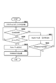
- the power receiving device 200 receives the ACK, it periodically starts transmitting the IDLE (S406), and connects to the second communication unit 106 of the power transmitting device 100 by BLE (S408).
- the power transmitting apparatus 100 determines whether the IDLE transmitted from the power receiving apparatus 200 has been received via the first communication unit 104. When IDLE is received, it progresses to S603. On the other hand, if IDLE has not been received, the process proceeds to S605.
- the power transmission device 100 extends Digital Ping during power transmission for a certain period (for example, 200 ms).
- the power transmitting apparatus 100 determines whether TERMINATE is received from the second communication unit 202 of the power receiving apparatus 200. When TERMINATE is received, the process ends. On the other hand, if TERMINATE is not received, the process returns to S602.
- the power transmitting apparatus 100 receives the TERMINATE from the second communication unit 202 of the power receiving apparatus 200. Has not been received, so the process returns to S602. Then, the power transmission device 100 again determines whether or not IDLE is received.
- the power transmission device 100 determines whether a time-out has occurred.
- the power transmission device 100 sets, as the timeout value, a value of 200 ms or more, which is a period in which the digital ping is extended in S603, for example. If a time-out has occurred, proceed to S606. On the other hand, if the timeout has not occurred, the process returns to S602, and it is determined again whether IDLE is received.
- the power receiving device 200 may transmit the next IDLE within, for example, a maximum of 19 ms from the rear end of the IDLE response packet (eg, ACK).
- the power receiving device 200 starts transmitting the IDLE, the power transmitting device 100 transmits the trailing end of the ACK to the IDLE, and the power receiving device 200 starts transmitting the next IDLE.
- the time is, for example, 50 ms.
- the power transmission device 100 can receive the IDLE without fail within 200 ms, which is the period during which the digital ping is extended, so that the power transmission device 100 can extend the digital ping period again.
- the power transmission device 100 Each time the IDLE is received, the power transmission device 100 resets the timer value to the initial value. This allows the packet to be transmitted to the power transmission device 100 by the first communication while the power reception device 200 is performing device authentication with the power transmission device 100 by the second communication. Therefore, the power transmission device 100 can continue to transmit the Digital Ping without a timeout. Further, the power transmission device 100 can perform higher-speed control communication using the second communication unit 106 while continuing the control communication using the first communication unit 104.
- the power transmitting apparatus 100 cannot receive the IDLE packet because the power receiving apparatus 200 has moved out of the power transmitting range of the power transmitting apparatus 100, a timeout occurs (YES in S605). Therefore, in S606, the power transmission device 100 stops Digital Ping.
- the power transmitting apparatus 100 transmits TERMINATE to the power receiving apparatus 200 via the second communication unit 106. This makes it impossible to perform control communication using the first communication unit 104 of the power transmission device 100, and when power transmission is stopped, the power transmission device 100 can also stop control using the second communication unit 106. If TERMINATE is received from the power receiving device 200 (YES in S604), the power transmitting device 100 can disconnect BLE and end the process.
- the power transmission device 100 may set the timeout value shown in FIG. 6 to a longer value during the second communication than in the case where only the first communication is performed.
- the power transmission device 100 transmits ACK (F307) to OOBReq (F306) and determines that the second communication is to be performed, the timeout value is only the first communication (the second communication is not performed). Set a longer value compared to Then, when TERMINATE is received (F318) and it is determined that the second communication is not performed, the timeout value is returned to the original value.
- the long value may be a value longer than 500 milliseconds, for example. Alternatively, it may be a sufficiently long value that includes the period from the transmission of ADV (F309) or the transmission of ACK (F307) to the reception of TERMINATE.
- the power receiving device 200 regularly transmits the IDLE at a longer cycle than when only the first communication is performed based on the timeout value set to a long value. Thereby, the same effect as that of the above-described embodiment can be obtained.
- the power transmission device 100 may determine whether or not a time-out has occurred based on the packet received in the second communication. When only the first communication is used, the power transmission device 100 determines the timeout based on the packet received via the first communication unit 104. On the other hand, after transmitting ACK (F307) to OOB Req (F306), the timeout is determined based on the packet received via the second communication unit 106. When using the second communication, the timeout value may be changed.
- the power receiving device 200 transmits a packet via the second communication unit 202 so that the power transmitting device 100 does not time out. Thereby, the same effect as that of the above-described embodiment can be obtained.
- the power transmission method of the wireless power transmission system according to the present invention is not particularly limited.
- a magnetic field resonance method in which electric power is transmitted by coupling by resonance (resonance) of a magnetic field between the resonator (resonance element) of the power transmission device and the resonator (resonance element) of the power reception device may be used.
- an electromagnetic induction method, an electric field resonance method, a microwave method, a power transmission method using a laser or the like may be used.
- the power transmitting device and the power receiving device may be, for example, image input devices such as imaging devices (cameras, video cameras, etc.) and scanners, or image output devices such as printers, copiers, and projectors. Further, it may be a storage device such as a hard disk device or a memory device, or may be an information processing device such as a personal computer (PC) or a smartphone.
- image input devices such as imaging devices (cameras, video cameras, etc.) and scanners
- image output devices such as printers, copiers, and projectors.
- a storage device such as a hard disk device or a memory device
- an information processing device such as a personal computer (PC) or a smartphone.
- FIGS. 4A and 4B, 5A and 5B, and 6 are started when the control unit is powered on. Note that the processing illustrated in FIG. 4 is realized by the control unit executing a program stored in the memory of the power receiving device. Further, the processes shown in FIGS. 5 and 6 are realized by the control unit executing a program stored in the memory of the power transmission device.
- FIGS. 4A and 4B, 5A and 5B, and 6 may be realized by hardware.
- a dedicated compiler may be used to automatically generate a dedicated circuit on the FPGA from a program for realizing each step.
- FPGA is an abbreviation for Field Programmable Gate Array.
- you may make it implement
- the present invention supplies a program that implements one or more functions of the above-described embodiments to a system or apparatus via a network or a storage medium, and one or more processors in a computer of the system or apparatus read and execute the program. It can also be realized by the processing. It can also be realized by a circuit (for example, ASIC) that realizes one or more functions.
- a circuit for example, ASIC
Abstract
受電装置200の制御部201は、第一通信部204を用いた制御通信から第二通信部202を用いた制御通信へ切り替えられた場合に、送電装置100からの送電が継続されるように、第一通信部204を介して送電装置100へ所定の通信を行う。
Description
本発明は、受電装置、受電装置の制御方法及びプログラムに関するものである。
無線電力伝送システムの技術開発が広く行われている。特許文献1では、非接触充電規格の標準化団体Wireless Power Consortium(WPC)が策定する規格(WPC規格)に準拠した送電装置および受電装置が開示されている。これらの送電装置および受電装置は、電力伝送に必要な制御情報を、送受電する電力に重畳する通信によってやりとりを行う。
特許文献2では、送電電力の制御のために送電装置と受電装置との間で実施される制御信号を、送電部及び受電部とは異なる周波数、異なるコイル(またはアンテナ)を介した通信部を用いた通信で通信する技術が開示されている。
無線電力伝送システムにおける制御通信には、データ量の少ないパケットや、データ量の多いパケットがある。しかしながら、従来技術では、複数の通信部を用いた通信が可能な無線電力伝送システムにおいて、それらのパケットを複数の通信部を使い分けて送受信することは行われていない。
本発明は、上記の課題に鑑みてなされたものであり、無線電力伝送の際に複数の通信部を好適に制御可能とする技術を提供する。
上記の目的を達成する本発明に係る受電装置は、
送電装置から無線で受電する受電手段と、
前記送電装置との間で無線電力伝送の制御通信を行う第一通信手段と、
前記送電装置との間で前記第一通信手段と異なる方式で無線電力伝送の制御通信を行う第二通信手段と、
前記第一通信手段を用いた制御通信から前記第二通信手段を用いた制御通信へ切り替えられた場合に、前記送電装置からの送電が継続されるように、前記第一通信手段を介して前記送電装置と所定の通信を行う制御手段と、
を備えることを特徴とする。
送電装置から無線で受電する受電手段と、
前記送電装置との間で無線電力伝送の制御通信を行う第一通信手段と、
前記送電装置との間で前記第一通信手段と異なる方式で無線電力伝送の制御通信を行う第二通信手段と、
前記第一通信手段を用いた制御通信から前記第二通信手段を用いた制御通信へ切り替えられた場合に、前記送電装置からの送電が継続されるように、前記第一通信手段を介して前記送電装置と所定の通信を行う制御手段と、
を備えることを特徴とする。
本発明によれば、無線電力伝送の際に複数の通信部を好適に制御することが可能となる。
本発明のその他の特徴及び利点は、添付図面を参照とした以下の説明により明らかになるであろう。なお、添付図面においては、同じ若しくは同様の構成には、同じ参照番号を付す。
添付図面は明細書に含まれ、その一部を構成し、本発明の実施の形態を示し、その記述と共に本発明の原理を説明するために用いられる。
一実施形態に係る送電装置の構成例を示すブロック図。
一実施形態に係る受電装置の構成例を示すブロック図。
一実施形態に係る無線電力伝送システムの動作シーケンス図。
一実施形態に係る受電装置が実施する処理の手順を示すフローチャート。
一実施形態に係る受電装置が実施する処理の手順を示すフローチャート。
一実施形態に係る送電装置が実施する処理の手順を示すフローチャート。
一実施形態に係る送電装置が実施する処理の手順を示すフローチャート。
一実施形態に係る送電装置が実施する送電停止の防止に関する処理の手順を示すフローチャート。
以下、図面を参照しながら実施形態を説明する。なお、以下の実施形態において示す構成は一例に過ぎず、本発明は図示された構成に限定されるものではない。
<送電装置の構成>
図1は、一実施形態に係る無線電力伝送システムに適用可能な送電装置の構成例を示すブロック図である。送電装置100はWPC規格に準拠しており、さらに機器認証プロトコルに対応しているとする。なお、本実施形態では、送電装置と受電装置とがWPC規格に準拠しているものとして説明するが、それに限定されず、他の無線電力伝送規格であってもよい。
図1は、一実施形態に係る無線電力伝送システムに適用可能な送電装置の構成例を示すブロック図である。送電装置100はWPC規格に準拠しており、さらに機器認証プロトコルに対応しているとする。なお、本実施形態では、送電装置と受電装置とがWPC規格に準拠しているものとして説明するが、それに限定されず、他の無線電力伝送規格であってもよい。
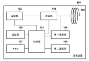
送電装置100は、制御部101、電源部102、送電部103、第一通信部104、送電コイル105、第二通信部106、メモリ107、及び認証部108を備えている。制御部101は、送電装置100全体を制御する。制御部101の一例はCPU(Central Processing Unit)である。電源部102は、少なくとも制御部101および送電部103が動作するための電源を供給する。送電部103は、送電コイル105を介して図2を参照して後述する受電装置200へ伝送する交流電圧および交流電流を発生させる。具体的には、送電部103は、電源部102が供給する直流電圧を、FET(Field Effect Transistor)を使用したハーフブリッジもしくはフルブリッジ構成のスイッチング回路で交流電圧に変換する。送電部103はFETのON/OFFを制御するゲ-トドライバを含む。また、送電部103は、WPC規格に対応した受電装置200の充電部に例えば15ワットの電力を出力する電力供給能力があるものとする。
第一通信部104は、受電装置200の通信部(図2の第一通信部204)との間で、WPC規格に基づいた無線電力伝送の制御通信を行う。本実施形態では、第一通信部104が実行する通信は、送電部103が発生する交流電圧または電流を変調し、無線電力伝送に用いるための信号を重畳する通信である。以下、第一通信部104と受電装置200の通信部(図2の第一通信部204)とで行う通信を第一通信という。
第二通信部106は、受電装置200の通信部(図2の第二通信部202)との間で、WPC規格に基づいた無線電力伝送の制御通信を行う。第二通信部106による通信は、送電部103の周波数と異なる周波数を使用する通信であり、送電コイル105とは異なるアンテナ(不図示)を使用する。本実施形態では、第二通信部106はBluetooth Low Energy(BLE)のペリフェラルとして動作するものとして説明を行う。ただし、BLEのセントラルや、Near Field Communication(NFC)またはWiFiなどであってもよい。本実施形態では、第二通信部106による通信は第一通信部104による通信と比較して、高速な通信が可能であるとする。以下、第二通信部106と受電装置200の通信部(図2の第二通信部202)とで行う通信を第二通信という。
また、第二通信部106は、制御部101によって制御されるが、送電装置100を内蔵する図示しない他の装置(カメラ、スマートフォン、タブレットPC、ラップトップ)の制御部により制御される構成であってもよい。
メモリ107は、送電装置100および受電装置200の状態を記憶する。また、送電装置100を動作させるためのコンピュータプログラムを記憶している。認証部108は、第一通信部104または第二通信部106を介して受電装置200との間で機器認証プロトコルを実行する。
なお、図1の例では、制御部101、電源部102、送電部103、第一通信部104、メモリ107、第二通信部106は別体として記載しているが、これらの内の任意の複数は、同一チップ内に実装されてもよい。
<受電装置の構成>
続いて、図2は、一実施形態に係る無線電力伝送システムに適用可能な受電装置の構成例を示すブロック図である。受電装置200はWPC規格に準拠しており、WPC規格v1.2.2に記載の機能を含み、加えて、機器認証プロトコルに対応しているとする。
続いて、図2は、一実施形態に係る無線電力伝送システムに適用可能な受電装置の構成例を示すブロック図である。受電装置200はWPC規格に準拠しており、WPC規格v1.2.2に記載の機能を含み、加えて、機器認証プロトコルに対応しているとする。
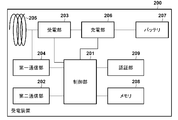
受電装置200は、制御部201、第二通信部202、受電部203、第一通信部204、送電コイル205、充電部206、バッテリ207、メモリ208、及び認証部209を備えている。
制御部201は、受電装置200全体を制御する。制御部201の一例はCPUである。受電部203は、受電コイル205を介して受電した送電コイル105からの交流電圧および交流電流を制御部201および充電部206などが動作する直流電圧および直流電流に変換する。受電部203は、充電部206がバッテリ207を充電するための電力を供給し、充電部206に15ワットの電力を出力する電力供給能力があるものとする。
第一通信部204は、送電装置100の第一通信部104との間で、WPC規格に基づいた無線電力伝送の制御通信を行う。この制御通信は、受電コイル205で受電した電磁波を負荷変調することで行う通信である。
第二通信部202は、送電装置100の第二通信部106との間で、WPC規格に基づいた無線電力伝送の制御通信を行う。第二通信部202による通信は、送電装置100の送電部103の周波数と異なる周波数を使用する通信であり、送電コイル105とは異なる図示しないアンテナを使用する。本実施形態では、第二通信部202はBLEのセントラルに対応しているものとして説明する。ただし、BLEのペリフェラルや、NFCまたはWiFiなどであってもよい。本実施形態では、第二通信部202による通信は第一通信部204による通信と比較して、高速な通信が可能であるとする。
また、第二通信部202は、制御部201によって制御されるが、受電装置200を内蔵する図示しない他の装置(カメラ、スマートフォン、タブレットPC、ラップトップ)の制御部により制御される構成であってもよい。
メモリ208は、送電装置100および受電装置200の状態を記憶する。また、受電装置200を動作させるためのコンピュータプログラムを記憶している。認証部209は、第一通信部204または第二通信部202を介して送電装置100との間で機器認証プロトコルを実行する。
<機能及び状態遷移>
ここで、WPC規格に準拠した送電装置100、受電装置200の機能および状態遷移について、図3から該当する部分を抜き出して概略的に説明する。図3は、一実施形態に係る無線電力伝送システムに適用可能な送電装置と受電装置とのシーケンス図である。
ここで、WPC規格に準拠した送電装置100、受電装置200の機能および状態遷移について、図3から該当する部分を抜き出して概略的に説明する。図3は、一実施形態に係る無線電力伝送システムに適用可能な送電装置と受電装置とのシーケンス図である。
送電装置100が起動すると、送電部103は、送電コイル105を介してAnalog Pingを送電する(F300)。Analog Pingとは送電コイル105の近傍に存在する物体を検出する為の微小な電力の信号である。送電装置100がAnalog Pingを送電しているとき、送電装置100はSelectionフェーズという状態にある。
送電装置100は、Analog Pingを送電した時の送電コイル105の電圧値または電流値を検出する。そして、電圧がある閾値を下回るもしくは電流値がある閾値を超えるなどの場合に送電コイル105の周辺に物体が存在すると判断し、送電装置100はPingフェーズに遷移する。
Pingフェーズでは、送電装置100はAnalog Pingより電力が大きいDigital Pingを送電する(F301)。Digital Pingの大きさは、少なくとも送電コイル105の近傍に存在する受電装置200および制御部201が起動するのに十分な電力であるものとする。
受電装置200の制御部201は、受電コイル205を介して受電した電力(Digital Ping)により起動する。起動すると、受電電圧の大きさを送電装置100へ通知し(F302)、Identification & Configuration(以下、I&Cフェーズという)へ遷移する。ここで、受電電圧通知は、第一通信部204を介した第一通信により行われる。
送電装置100は、受電装置200から受電電圧通知を受信すると、I&Cフェーズへ遷移する。続いて、受電装置200は自身の製造者を示す製造者コードやデバイス識別情報を含むID Packetを送電装置100へ送信する(F303)。また、送電装置100は、自身が準拠している規格バージョン等を含むConfiguration Packetを送電装置100へ送信する(F304)。
送電装置100は、受電装置200からConfiguration Packetを受信し、かつ受電装置200が対応する規格バージョンが例えばv1.2.2以上のバージョンであるか否かを判定する。規格バージョンがv1.2.2以上のバージョンである場合、Configuration Packetに含まれる情報を許諾したことを示すACKを受電装置200へ送信する(F305)。そして、Negotiationフェーズに遷移する(F319)。同様に、受電装置200は、ACKを受信すると(F305)、Negotiationフェーズに遷移する(F319)。なお、本実施形態に特有の所定の処理(F306~F318、F323、F324)についての説明は後述する。
そしてNegotiationフェーズ(F319)では、送電装置100及び受電装置200は、受電装置200が必ず受電できる電力の大きさを示すGuaranteed Power(以下、GPという)を決めるための交渉を行う。具体的には、受電装置200がGPの候補となる値を送電装置100へ通知する。そして、送電装置100は当該通知を許諾もしくは拒否する。受電装置200は充電部206に15ワットの電力を出力する電力供給能力があるので、GPの値の候補として最大15ワットを通知できる。また、送電装置100は、GPの値として最大15ワットを許諾することができる。
GPの交渉が終了すると、送電装置100及び受電200は、Calibrationフェーズ(F320)へ遷移する。Calibration フェーズ(F320)では、詳細は説明しないが、送電装置10が送電コイル105近傍に受電装置200ではない物体が存在することを検出する異物検出機能に必要なパラメータを決定する。Calibrationフェーズでは、受電装置100は、受電部203から負荷となる充電部206へ電力を供給する処理も行う。その後、送電装置100及び受電装置200は、Power Transferフェーズ(F321)へ遷移し、受電装置200はバッテリ207を充電する。
以上が、WPC規格に準拠した送電装置100及び受電装置200の機能および状態遷移に関する概略説明である。
<機器認証>
続いて、機器認証について説明する。機器認証は、送電装置100及び受電装置200の間で互いの正当性を確認する処理であり、双方向で行われる処理である。具体的には、送電装置100が受電装置200の正当性を確認してもよいし、受電装置200が送電装置100の正当性を確認してもよい。そして、送受電する電力の大きさは機器認証の結果に応じて決定する。
続いて、機器認証について説明する。機器認証は、送電装置100及び受電装置200の間で互いの正当性を確認する処理であり、双方向で行われる処理である。具体的には、送電装置100が受電装置200の正当性を確認してもよいし、受電装置200が送電装置100の正当性を確認してもよい。そして、送受電する電力の大きさは機器認証の結果に応じて決定する。
具体的には、送電装置100は、正当性を確認できなかった受電装置に対しては、正当性を確認できた受電装置に送電する電力と比較して小さい電力で送電を行う。そのため、送電装置100は、Negotiationフェーズにおいて、正当性を確認できなかった受電装置に対して、正当性を確認できた受電装置と比較して小さいGPしか許容せず、かつ自身が供給できるGPの最大値である15ワットは許容しない。正当性を確認できなかった受電装置は粗悪な受電装置の可能性があり、正当な受電装置と比較して過度に発熱するなどの可能性があるが、これにより、過度な発熱を防止することができる。
同様に、受電装置200は、正当性を確認できなかった送電装置に対して、正当性を確認できた送電装置から受電する電力と比較して小さいGPを要求する。つまり、受電装置200は、Negotiationフェーズにおいて、正当性を確認できなかった送電装置に対して、自身のGPの最大値である15ワットを要求しない。正当性を確認できなかった送電装置は、粗悪な送電装置である可能性があり、正当な送電装置と比較して過度に発熱するなどの可能性があるが、これにより、過度な発熱を防止することができる。
また、機器認証はNegotiationフェーズよりも前に実施する。なぜなら、機器認証の結果は、Negotiationフェーズで交渉するGPの大きさに影響を及ぼすためである。仮にNegotiationフェーズでGPが決定した後に機器認証を行った場合は、機器認証の結果に基づいて、再度Negotiationフェーズに遷移し、GPの交渉をやり直すなど無駄な処理が発生する可能性があるからである。
また、より早期に機器認証処理を終了させるには、機器認証を第一通信と比較して高速な第二通信で行う方法がある。
ここで、機器認証を第二通信で行った場合の現象について説明する。まず、WPC規格では、送電装置100が、受電装置200を検出できない場合に、送電を停止する仕組みがある。この仕組みにより、受電装置200が送電装置100から物理的に離れたりして、受電装置200が検出できなくなった場合に、送電装置100が送電を停止できる。そのため、受電装置200が送電範囲に存在しないにも関わらず不要な電波を出し続けることを防止することができる。
具体的には、I&Cフェーズでは、受電装置200の第一通信部204が送信したパケットの後端を送電装置100が受信してから、所定の時間(25ms)内に次のパケットの先頭を受信しない場合に、送電装置100は送電を停止する。また、Negotiationフェーズでは、受電装置200の第一通信部204が送信したパケットに対して送電装置100が応答を送信してから、所定の時間(250ms)内に次のパケットを受信しない場合に、送電装置100は送電を停止する。またPower Transferフェーズでも同様に、受電装置200の第一通信部204が送信したパケットの後端を送電装置100が受信してから、所定の時間(1500ms)内に次のパケットの先頭を受信しない場合、送電装置100は送電を停止する。このように、送電装置100はタイムアウトによって送電を停止する機能を有する。
そしてI&Cフェーズが終了し、Negotiationフェーズに遷移した際に、第二通信で機器認証(制御通信)を行った場合は、先に述べた理由でGPの交渉を第二通信で行う機器認証の結果に基づいて行う。そのため、第一通信で受電装置が送信すべきパケットが存在しない。すると、送電装置は、すでに説明したように受電装置から第一通信で所定の時間、パケットを受信せず、送電を停止してしまう。また、第二通信は、他の無線通信との干渉などにより再送が発生しやすいため、第一通信を行わない時間がより長くなる可能性もある。
これに対して、本実施形態に係る受電装置は、第二通信で送電装置との間で機器認証を行っている間も、第一通信で送電装置にパケットを送信する。これにより、送電装置が送電を停止すること防止することが可能となる。
<無線電力伝送システムの動作シーケンス>
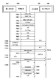
改めて図3を用いて、送電装置100及び受電装置200を含む無線電力伝送システムのシーケンスの詳細な手順を説明する。前述した通り、送電装置100はAnalog Pingを送信し(F300)、送電コイルの近傍に物体が存在すると判断すれば、Digital Pingを送電する(F301)。受電装置200はDigital Pingを受電すると(F301)、制御部201を起動する。そしてDigital Pingの受電電圧を送電装置200に通知し(F302)、I&Cフェーズへ遷移する。
改めて図3を用いて、送電装置100及び受電装置200を含む無線電力伝送システムのシーケンスの詳細な手順を説明する。前述した通り、送電装置100はAnalog Pingを送信し(F300)、送電コイルの近傍に物体が存在すると判断すれば、Digital Pingを送電する(F301)。受電装置200はDigital Pingを受電すると(F301)、制御部201を起動する。そしてDigital Pingの受電電圧を送電装置200に通知し(F302)、I&Cフェーズへ遷移する。
そして、受電装置200はID Packetを送信し(F303)、Configuration Packetを、第一通信部104を介して送電装置100へ送信する(F304)。送電装置200は、Configuration Packetを受信すると、ACKを送信する(F305)。受電装置200はACKを受信する(F305)と、OOB Reqを送信する(F306)。
Configuration Packetによれば、受電装置200は機器認証に対応しており、さらにBLEを使用した機器認証にも対応しているものとする。また、送電装置100も機器認証に対応しており、さらにBLEを使用した機器認証にも対応しているものとする。よって、送電装置100はBLEによる機器認証を行うことを許諾するACKを送信する(F307)。
受電装置200は当該ACKを受信する(F307)と、第一通信部104を介してIDLEの送信を開始する(F308)。送電装置100はIDLEに対してACKを送信する(F323)。ここで、受電装置200がIDLEに対するACKを受信しなければ、受電装置200は送電装置100に対して送電停止を指示するEPTを送信してもよい。また、受電装置200がIDLEに対してACKではない他のパケット、例えばNAKやND(Not Defined)を受信した場合にも、受電装置200はEPTを送信してもよい。
NDパケットとは、受電装置200が送信したパケットを送電装置100が理解できなかった場合に、送電装置100が送信する応答パケットである。送電装置100は、受電装置200から受信したOOB Reqに対してACKを受電装置200へ送信していた場合(F307)、IDLEを送信することでタイムアウトによる送電停止を回避するという意図を、送信装置100は理解できるはずである。それにも関わらず、受電装置200が送電装置100からNAKやNDを受信した場合(F323)、受電装置200は送電装置100が故障したと解釈し、EPTの送信により送電を停止させることができる。
続いて、送電装置100は、第二通信部106を介してADVを送信する(F309)。そして、受電装置200は、第二通信部202を介してCONNECTを送信する(F311)。その後、受電装置200は、Auth Reqを送信し(F312)、送電装置100からACKを受信した(F313)後に、受電装置200は自身がイニシエータとして動作するAuth処理を実施する(F314)。
送電装置100および受電装置200が第二通信による制御通信を行っている間も、受電装置200は一定時間が経過する前に(例えば定期的に)IDLEを送信する(F310、F324)。そして、送電装置100は当該IDLEに対してACKで応答する(不図示)。続いて、送電装置100はAuth Reqを送信し(F315)、受電装置200からACKを受信した(F316)後、送電装置100自身がイニシエータとして動作するAuth処理を実施する(F317)。
Auth処理が終了すると、受電装置200は、送電装置100へTERMINATEを送信し(F318)、BLEの通信を終了する。Auth処理が終了したので、送電装置100及び受電装置200はGPのNegotiationを実施し(F319)、Calibrationフェーズ(F320)へ、そしてPTフェーズ(F321)へ遷移する。
ここで、Specific RequestのうちPacket TypeがGuaranteed Powerであるパケットであって、受電装置200が所望のGPを送電装置100へ通知するパケットを送信した後は、送電装置100および受電装置200は、決められたタイミングでパケットを送受信することがWPC規格で規定されている。よって、以降、送電装置100がタイムアウトで送電を停止することがない。そのため、受電装置200は、タイムアウトが発生しないことを目的として送信していたIDLEの送信を停止する。
以上説明したように、第二通信で制御通信を行っている間は、受電装置が第一通信でIDLEを送信することで、送電装置が送電を停止すること防止することができる。さらに、第一通信で送信すべきパケットが存在するGPの交渉以降は、IDLEの送信を停止することで、無駄なパケットの送信を停止し、処理を軽減することができる。
なお、送電装置100が第二通信を行っている間に、第二通信部106を使用できなくなる状況が発生する可能性もある。例えば、送電装置100を内蔵した図示しない装置が第二通信部106を占有してしまう場合などである。その場合、送電装置100は、第二通信部106を第二通信に使用できないと判断した場合には、IDLEに対してNAKで応答するように構成してもよい。
受電装置200は、NAKを受信すると、第二通信で行っていた制御通信を第一通信に切り替える。具体的には、NAKを受信した後、TERMINATEを受信しなければ、受電装置200はTERMINATEを送信する。そして、第二通信で実施していた制御通信を、第一通信で実施する。当然ながら、受電装置200は、第一通信に切替えた時点で、第一通信で送信すべきパケットが存在するので、IDLEの送信は不要であり送信を停止する。これにより第二通信が使用できない場合でも、送電装置100との通信を継続することができる。
また、受電装置200の第二通信部202が動作するための電力を、受電装置200の図示しないバッテリが供給している。バッテリ残量がBLEを駆動するのに十分でない場合は、受電装置200はConfiguration PacketのBLE bitに「0」を格納するようにしてもよい。また、受電装置200を内蔵した図示しない装置がBLEを使用中であり、認証処理(制御通信)にBLEを使用できない場合にも、受電装置200はConfiguration PacketのBLE bitに「0」を格納するようにしてもよい。これにより、受電装置200がBLEを第二通信に使用できないにも関わらず、送電装置100がADVを送信するといった不具合の発生を回避することができる。
<受電装置の処理>
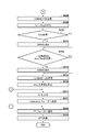
続いて、図4A及び図4Bのフローチャートを参照して、本実施形態に係る受電装置200が実施する処理の手順を説明する。まずS401において、受電装置200は、図3を参照して説明したSelectionフェーズおよびPingフェーズの処理を実行する。
続いて、図4A及び図4Bのフローチャートを参照して、本実施形態に係る受電装置200が実施する処理の手順を説明する。まずS401において、受電装置200は、図3を参照して説明したSelectionフェーズおよびPingフェーズの処理を実行する。
S402において、受電装置200は、ID PacketとConfiguration Packetを送電装置100へ送信する。ここで、受電装置200は、Configuration Packetにおいて、機器認証に対応していることと、機器認証をBLEによる第二通信で実施可能であることとを送電装置100へ通知する。具体的には、WPC規格のConfiguration Packetで使用されていないReserve領域を用いて、Authentication bit(以下Auth bit)と、BLE bitとが「1」であるConfiguration Packetを送電装置100へ送信する。Auth bitは機器認証に対応していることを示すためのbitである。また、BLE bitは機器認証をBLEによる第二通信で実施可能であることを示すためのbitである。
S403において、受電装置200は、Configuration Packetに対するACKを送電装置から受信したか否かを判定する。WPC規格v1.2.2によれば、Configuration Packetに対してACKを受信した場合、受電装置200は、送電装置がNegotiationフェーズに対応していることを認識できる。ACKを受信した場合、受電装置200はNegotiationフェーズに遷移し、S404へ進む。一方、ACKを受信していない場合、S418へ進む。
S404において、受電装置200は、BLEによる第二通信を要求することを示すOut OFBand Request(OOB Req) パケットを、第一通信部202を介して送信する。OOB Reqパケットは、送電装置100が第二通信部104としてBLEに対応しており、さらに第二通信部104を用いた機器認証に対応しているか否かを確認するために送信される。
OOB ReqパケットはBLE bitを含んでおり、BLE bitが「1」であれば、第二通信としてBLEを使用することを要求することを示している。また、OOB ReqパケットはAuth bitを含んでおり、Auth bitが「1」であれば、第二通信を使用した機器認証を要求することを示している。
また、OOB Reqパケットは、第二通信の種類としてNFCを使用することを要求するNFC bitを含んでもよい。NFC bitが「1」であれば、第二通信としてNFCを使用することを要求することを示している。同様に、第二通信の種類としてWiFiを使用することを要求するWiFi bitを含んでもよい。さらに、WPC規格で定義されているGeneral RequestやSpecific Requestのうち、Packet typeが定義されていないReserved PacketやProprietary Packetパケットを、OOB Reqパケットとして定義してもよい。
S405において、受電装置200は、送電装置100から、OOB Reqの応答としてACKを受信したか否かを判定する。受電装置200が送電装置100からOOB Reqの応答としてACKを受信した場合、受電装置200は、送電装置100が第二通信部104としてBLEに対応しており、さらに第二通信部104を用いた機器認証に対応していることを認識できる。ACKを受信した場合、S406へ進む。一方、ACKを受信していない場合、S420へ進む。
S406において、受電装置200は、Negotiationフェーズに遷移してからGPの交渉を行うまでの間、送電装置100へ、WPC規格で定められたタイミングで第一通信部204を介して定期的にIDLEを送信する。IDLEは例えば図3のF308、F310、F324に対応している。具体的には、送電装置100が第一通信部104を介して送信する、IDLEの応答パケット(例えばACK)の後端、つまり前のパケットの後端から、WPC規格で定められた最大19ms以内に、受電装置200は次のIDLEを送信する。ここでIDLEパケットとは、第二通信で制御通信を行うときに、送電装置100に送電を停止させないために定期的に送信するパケットである。
OOB Reqを理解できる送電装置100は、IDLEを受信すると、応答としてACKを送信するようにしてもよい。送電装置100は定期的にIDLEを受信するので、タイムアウトにより送電を停止することがない。従って、第二通信で機器認証を行った場合に、送電装置が第一通信でパケットを一定時間受信せずに、送電を停止してしまうことを防止することができる。
なお、受電装置200が送信するIDLEは、送電装置100がタイムアウトと判断しないようにすることが目的なので、他のパケットを使用してもよい。例えば、General RequestまたはSpecific Requestパケットの内、Packet Typeが定義されていないReserved PacketやProprietary Packetであってもよい。
続いて、S407において、受電装置200は、S405でACKを受信してから一定時間内に送電装置100の第二通信部104からAdvertise Indicationパケット(以下ADVという)を受信したか否かを判定する。ここで、ADVとは、BLEのペリフェラルが送信する情報である。ADVには、当該ペリフェラルの固体識別情報であるBluetooth Device Address(以下BD アドレスという)や、対応しているプロファイル情報(サービス情報)が格納されている。一定時間内にADVを受信した場合、S408へ進む。一方、一定時間内にADVを受信しなかった場合、S421へ進む。
なお、受電装置200が受信するADVが、送電装置100が送信したADVであるか否かを判定するために、受電装置200は、事前に送電装置100の第二通信部104のBD アドレスを受信しておいてもよい。具体的には、S405でのACK受信後に、受電装置200が第一通信部204を介して、能力を問い合わせるパケットとしてWPC規格で定義されているパケットを送電装置100へ送信する。そして、送電装置100が当該パケットの応答としてBDアドレスを格納した応答を、第一通信部104を介して受電装置200へ送信してもよい。また、BDアドレスを問い合わせるパケットを新たに割り当ててもよい。例えばGeneral RequestもしくはSpecific Requestのうち、Packet typeが定義されていないReserved PacketやProprietary Packetパケットを割り当ててもよい。
受電装置200は、送電装置100のBDアドレスを受信し、第二通信部202を介して受信したBDアドレスと一致するか否かを判定することによって、送電装置100からADVを受信したか否かを判定することができる。
S408において、受電装置200は、第二通信部202を介して送電装置100にBLEによる接続を行うことを示すCONNECTパケットを送信する。
S409において、受電装置200は、送電装置100との間でBLEによるデータの送受信が可能となった後に、Auth Reqパケットを、第二通信部202を介して送電装置100へ送信する。Auth Reqパケットは、送電装置100の正当性を確認するための機器認証を要求することを示すためのパケットである。
Auth Reqパケットは、パケットの送信元(受電装置200)が送信先(送電装置100)の正当性を確認する役割であるイニシエータとして動作し、送信先が正当性を確認される役割であるレスポンダとして動作することを要求する情報を含む。
S410において、受電装置200は、Auth Reqに対して許諾を示すACKを送電装置100から受信したか否かを判定する。許諾を示すACKを受信した場合、S411へ進む。一方、許諾を示すACKを受信しなかった場合、S412へ進む。
S411において、受電装置200は、機器認証プロトコルであるAuthenticationを実施する。Authentication処理(以下Auth処理)は、電子証明書を使用した認証プロトコルの1つである。受電装置200は、Auth処理において送電装置100の正当性を確認する。
S412において、受電装置200は、S411での送電装置100の正当性の確認後或いはS410でACKを受信しなかった場合、一定時間内に送電装置100から第二通信部202を介してAuth Reqを受信したか否かを判定する。Auth Reqは、送電装置100が送信先(受電装置200)の正当性を確認する役割であるイニシエータとして動作し、送信先である受電装置200が正当性を確認される役割であるレスポンダとして動作することを示す情報を含む。Auth Reqを受信した場合、S413へ進む。一方、Auth Reqを受信しなかった場合、S414へ進む。
S413において、受電装置200は、自身がレスポンダとして動作するAuthenticationを行う。ここで、受電装置200が、S411のAuth処理において送電装置100の正当性を確認できなかった場合、つまり機器認証が失敗した場合は、送電装置100をイニシエータとするAuth処理を行わないようにしたい。その場合は、送電装置100が送信するAuth Reqを待たずにBLE接続を切断してもよい。なぜなら、送電装置100の正当性が確認できなかったために、送電装置100をイニシエータとするAuth処理の結果に関わらず、後述するNegotiationフェーズにおいて、送電装置100に要求するGPを制限する必要があるからである。無駄なAuth処理を行わないようにすることで、送電開始までの処理を高速化することができる。なお、受電装置200は、正当性が確認できなかった送電装置の識別情報、例えばBDアドレスまたはWPC規格によって規定される識別情報をメモリに記憶しておき、以降BLE接続をしないように構成してもよい。
S414において、受電装置200は、第二通信部202を介して、BLE接続を切断することを意味するTERMINATE Indication(以下、TERMINATEという)を送電装置100へ送信する。
そして、S415において、受電装置200は、BLEの切断以降は、第二通信部202は使用せずに、第一通信部204を使用すると判定し、IDLEの送信を停止する。このように、第二通信部202を使用する間、第一通信部204を介してIDLEパケットを送電装置100に送信することで、送電装置100が送電を停止することを防止することができる。
さらに、機器認証の間IDLEを送信し、GPの交渉を行わないことにより、BLEを介して機器認証を行っている間に、第一通信でGPの交渉が行われ、機器認証終了後にGPの再交渉が必要になってしまうことを防止することができる。また、BLEを切断し、第二通信を用いた制御通信を行わない場合は、IDLEの送信を停止することで、無駄なパケットの送信をせず、制御部の処理を軽減することができる。
S416において、受電装置200は、送電装置100との間でGPの交渉を行う。ここで、受電装置200は送電装置100の正当性が確認されている場合、GPとして最大値である15ワットを、第二通信部202を介して要求する。その場合、送電装置100も同様に受電装置200の正当性を確認しているので、自身のGPの最大値である15ワットを超えない範囲で、受電装置200の要求を許諾する。
続いて、S417において、受電装置200は、Calibrationフェーズへ遷移する。そして、S418において、受電装置200は、PTフェーズへ遷移して、送電装置100から受電した電力で充電部206へ最大15ワットの電力を供給する。そして、充電が終了すると、S419において、受電装置200は、第一通信部204を介して送電装置100へ送電停止を指示するEnd Power Transfer(EPT)を送信する。
S420において、受電装置200は、拒否を示す応答であるNAKを受信したか否かを判定する。NAKを受信した場合、S423へ進む。一方、NAKを受信しなかった場合、S418へ進み、PTフェーズへ遷移して受電電力を最大5ワットとして充電を開始する。
S421において、受電装置200は、第二通信は使用せず、第一通信を使用してAuthenticationを行うと判断する。S422において、受電装置200は、IDLEの送信を停止する。S423において、受電装置200は、第一通信部204を介した第一通信でAuthenticationを実施する。その後、S416へ進み、GPの交渉を行う。
以上の一連の処理によれば、送電装置及び受電装置が、第一通信と第二通信とを好適に制御可能となる。
以上説明したように、S407でADVを受信する時間を、S405でACKを受信してから一定時間内に制限する。これにより、送電装置100又は受電装置200のBLEが正常に動作していない場合、もしくは、電波環境が悪いためにADVを受信できない場合などに、第一通信で機器認証を行うことができる。また、S421において第一通信で機器認証を行うと判断したら、S422でIDLEの送信を停止することで、無駄なパケットの送信を防止することができる。
なお、一定時間内にADVを受信しなかった場合に、S423において受電装置200が第一通信でAuthenticationを実施する例を説明したが、この例に限定されない。一定時間内にBLEを使用した通信を開始しなかった場合もしくはBLEによる接続を確立できなかった場合に、第一通信でAuthenticationを実施する構成としても、同様の効果が得られる。
また、受電装置200がOOB Reqを送信することで、送電装置100が第二通信部104としてBLEに対応しており、さらに第二通信部104を用いた機器認証に対応しているかどうかを確認する例を説明した。
しかし、これに限らず、OOB Reqの送信に先立って送電装置100の能力を問い合わせてもよい。具体的には、General Request(Power Transmitter Capability)(括弧内はパケットタイプを示す)を、OOB Reqに先立って、受電装置200が第一通信部204を介して送信する。General Request(Power Transmitter Capability)は、WPC規格で規定されているGeneral Requestパケットの内、送電装置の能力を問い合わせるためのパケットとして定義されている。そして、送電装置100は、Power Transmitter Capability Packetを、第一通信部104を介して受電装置200へ送信してもよい。Power Transmitter Capability Packetは、BLE bitと、Auth bitと、Enable bitとを含むパケットである。BLE bitは、第二通信としてBLEに対応していることを示すためのbitである。Auth bitは、BLEを使用した機器認証処理に対応していることを示すためのbitである。Enable bitは、現在BLEを使用した認証処理を行うことが可能かどうかを示すためのbitである。
そして、受電装置200はBLE bitが「1」で、Auth bitが「1」で、かつEnable bitが「1」である場合に、OOB Reqを送信するように構成する。そして、そうでない場合(第二通信部202で機器認証できない場合)は、OOB Reqを送信しないように構成する。これにより、無駄なOOB Reqの送信を防止することができる。
なお、送電装置100又は当該送電装置100を内蔵する装置(不図示)がBLEを使用中であり、認証処理(制御通信)にBLEを使用できない場合には、送電装置100はEnable bitに「0」を格納する。また、BLEが動作するための電力をバッテリ(不図示)が供給しており、バッテリ残量がBLEを駆動するのに十分でない場合にも、送電装置100はEnable bitに「0」を格納する。
また、送電装置100は、第二通信部104とは異なる第二通信部として機能する図示しない第三通信部(例えばNFC)を備えてもよい。その場合、第三通信部に対応していることを示すbitと、それを用いた機器認証に対応していることを示すbitと、現在第三通信部を使用した認証処理を行うことが可能かどうかを示すEnable bitとを、さらに設けてもよい。
これにより、受電装置200と送電装置100とが複数の第二通信に対応している場合に、柔軟に対応することができる。例えば、送電装置100及び受電装置200が第二通信としてBLE及びNFCに対応している場合を考える。送電装置100がBLEでは機器認証できず(Auth bit または Enable bit が0)、NFCでは機器認証できる場合(Auth bit及びEnable bitがともに1)に、NFCによる機器認証を行うことができる。この時、受電装置200は、NFC bitが「1」でAuth bitが「1」であるOOB Reqを送信する。
<送電装置の処理>
次に、図5A及び図5Bのフローチャートを参照して、本実施形態に係る送電装置100が実施する処理の手順を説明する。
次に、図5A及び図5Bのフローチャートを参照して、本実施形態に係る送電装置100が実施する処理の手順を説明する。
S501において、送電装置100は、SelectionフェーズおよびPingフェーズの処理を実行する。S502において、送電装置100は、ID Packet及びConfiguration Packetを受電装置200から受信する。送電装置100は、Configuration Packetを受信したことにより、受電装置200が機器認証に対応していること、および、機器認証をBLEによる第二通信で実施可能であることを認識できる。
S503において、送電装置100は、第一通信部104を介してACKを送信する。S504において、送電装置100は、受電装置200から送信されたOOB Reqを受信したか否かを判定する。OOB Reqを受信した場合、S505へ進む。一方、OOB Reqを受信していない場合S522へ進む。
S505において、送電装置100は、自身が現在機器認証にBLEを利用可能であるか否かを判定する。BLEを利用可能である場合、S506へ進む。一方、BLEを利用可能ではない場合、S521へ進む。
S506において、送電装置100は、OOB Reqに応答してACKを受電装置200へ送信する。ACKを送信後、S507において、送電装置100は、一定時間内に、第二通信部106を介してADVを送信する。S508において、送電装置100は、受電装置200からCONNECTを受信したか否かを判定する。CONNECTを受信した場合、S509へ進む。一方、CONNECTを受信していない場合、S522へ進む。
続いて、S509において、送電装置100は、受電装置200から、受電装置200をイニシエータとするAuth Reqパケットを受信したか否かを判定する。Auth Reqパケットを受信した場合、S510へ進む。一方、Auth Reqパケットを受信していない場合、S512へ進む。
S510において、送電装置100は、Auth Reqパケットの受信に応じてACKを送信する。S511において、送電装置100は、自身がレスポンダとして動作するAuth処理を行う。S512において、送電装置100は、Auth処理の終了後、自身がイニシエータとなるAuth処理を要求するAuth Reqを受電装置200へ送信する。また、CONNECTを受信し、BLEによる通信可能になった状態で(S508でYES)、一定時間内に自身がレスポンダとして動作するAuth Reqを受信しなかった場合(S509でNO)にも、S512へ進んでいる。この場合にも、S512において、送電装置100は、自身がイニシエータとなるAuth処理を要求するAuth Reqを受電装置200へ送信する。
S513において、送電装置100は、S512で送信したAuth Reqに対して、受電装置200からACKを受信したか否かを判定する。ACKを受信した場合、S514へ進む。一方、ACKを受信していない場合、S515へ進む。
S514において、送電装置100は、自身がイニシエータとして動作するAuth処理を行う。S515において、送電装置100は、受電装置200からTEMINATEを受信したか否かを判定する。TEMINATEを受信した場合、S517へ進む。一方、TEMINATEを受信していない場合、S516へ進む。S516において、送電装置100は、受電装置200へTERMINATEを送信し、第二通信部106を介した通信を終了する。
そして、S517において、送電装置100は、Negotiationフェーズで、受電装置200との間でGPの交渉を行う。ここで、受電装置200は送電装置100の正当性を確認している場合、GPとして最大値である15ワットを要求する。その場合、送電装置100も同様に受電装置200の正当性を確認しているので、自身のGPの最大値である15ワットを超えない範囲で、受電装置200の要求を許諾する。
続いて、S518において、送電装置100は、Calibrationフェーズへ遷移する。S519において、送電装置100は、PTフェーズへ遷移して、受電装置200の充電部206へ最大15ワットの電力を供給する。
そして、充電が終了すると、S520において、送電装置100は、受電装置200の第一通信部204を介して送信された、送電停止を指示するEPTを受信する。
また、S504でOOB Reqを受信した時点で、BLEが利用可能でない場合(S505でNO)、S521において、送電装置100は、受電装置200に対してNAKを送信する。その後、S522へ進む。
S522において、送電装置100は、Auth処理に第二通信を使用せず、第一通信を使用すると判断する。そして、S523において、第一通信でAuth処理を実施する。その後、S517へ進む。
なお、S511において、送電装置100は、受電装置200の正当性を確認できなかった場合、つまり機器認証が失敗した場合は、送電装置100はAuth Reqを送信せずに、BLE接続を切断してもよい。これは、送電装置100をイニシエータとするAuth処理を行わないようにするためである。
なぜなら、送電装置100の正当性が確認できなかったので、送電装置100をイニシエータとするAuth処理の結果に関わらず、Negotiationフェーズで、送電装置100は受電装置200が要求するGPを制限する必要があるからである。このように、無駄なAuth処理を行わないようにすることで、送電開始までの処理を高速化することができる。
<送電装置の処理>
続いて、図6のフローチャートを参照して、本実施形態に係る送電装置100が、第二通信で機器認証を行った場合であっても送電を停止しないことを説明する。
続いて、図6のフローチャートを参照して、本実施形態に係る送電装置100が、第二通信で機器認証を行った場合であっても送電を停止しないことを説明する。
S601において、送電装置100は、受電装置200から送信されたOOB Reqに対して、第一通信部104を介してACKを送信する。これに対して、受電装置200は、ACKを受信すると定期的にIDLEの送信を開始し(S406)、送電装置100の第二通信部106とBLEによる接続を行う(S408)。
S602において、送電装置100は、受電装置200から送信されたIDLEを、第一通信部104を介して受信したか否かを判定する。IDLEを受信した場合、S603へ進む。一方、IDLEを受信していない場合、S605へ進む。
S603において、送電装置100は、送電中のDigital Pingを一定期間(例えば200ms)延長する。S604において、送電装置100は、受電装置200の第二通信部202からTERMINATEを受信したか否かを判定する。TERMINATEを受信した場合、処理を終了する。一方、TERMINATEを受信していない場合、S602に戻る。
なお、送電装置100の第二通信部106と受電装置200の第二通信部202との間でAuth処理を実施中である場合、送電装置100は、受電装置200の第二通信部202からTERMINATEを受信しておらず、従ってS602に戻る。そして、送電装置100は、再びIDLEを受信したか否かの判定を行う。
S605において、送電装置100は、タイムアウトが発生したか否かを判定する。ここで、送電装置100は、タイムアウトの値として、例えばS603でDigital Pingを延長した期間である200ms以上の値を設定しておく。タイムアウトが発生した場合、S606へ進む。一方、タイムアウトが発生していない場合、S602に戻って、再びIDLEを受信した否かの判定を行う。
ここで、受電装置200は、IDLEの応答パケット(例えばACK)の後端から例えば最大19ms以内に、次のIDLEを送信するようにしてもよい。受電装置200がIDLEの送信を開始して、当該IDLEに対して送電装置100がACKの後端を送信し、受電装置200が次のIDLEの送信を開始するまでを1サイクルとして、1サイクルの時間を例えば50msとする。これにより、Digital Pingを延長している期間である200ms以内に、送電装置100は必ずIDLEを受信することができるので、送電装置100は再びDigital Pingの期間を延長することができる。
そして、IDLEを受信する度に送電装置100はタイマの値を初期値にリセットする。これにより、受電装置200が第二通信で送電装置100と機器認証を行っている間も、第一通信で送電装置100にパケットを送信することができる。従って、送電装置100は、タイムアウトが発生することなく、Digital Pingを送信し続けることができる。また、送電装置100は、第一通信部104を用いた制御通信を継続したまま、第二通信部106を用いてより高速な制御通信を行うことが可能となる。
また、受電装置200が送電装置100の送電可能な範囲外に移動したなどの理由で、送電装置100がIDLEパケットを受信できなくなった場合は、タイムアウトが発生する(S605でYES)。そのため、S606において、送電装置100はDigital Pingを停止する。
そして、S607において、送電装置100は、受電装置200に対して第二通信部106を介してTERMINATEを送信する。これにより、送電装置100の第一通信部104を用いた制御通信が不可能になり、送電を停止した場合に、送電装置100は第二通信部106を用いた制御も停止することができる。また、受電装置200からTERMINATEを受信すれば(S604でYES)、送電装置100はBLEを切断し、処理を終了することができる。
<変形例>
上述の実施形態では、送電装置200がタイムアウトを起こさないように、第二通信を行っている間、受電装置100は第一通信で定期的にIDLEパケットを送信する例を説明した。
上述の実施形態では、送電装置200がタイムアウトを起こさないように、第二通信を行っている間、受電装置100は第一通信で定期的にIDLEパケットを送信する例を説明した。
その際、送電装置100は、第二通信を行う間は、図6に示すタイムアウトの値を第一通信だけを行う場合と比較して長い値に設定してもよい。
送電装置100は、OOB Req(F306)に対してACK(F307)を送信し、第二通信を行うと判断した後は、タイムアウトの値を第一通信のみを行う場合(第二通信を行わない場合)と比較して長い値に設定する。そして、TERMINATEを受信して(F318)、第二通信を行わないと判断した場合に、タイムアウト値を元の値に戻す。長い値とは、例えば500ミリ秒より長い値であってもよい。或いは、ADV(F309)を送信してから、もしくは、ACK(F307)を送信してからTERMINATEを受信するまでの間の期間を含むような、十分長い値であってもよい。
受電装置200は、第二通信を使用する場合は、長い値に設定したタイムアウト値に基づいて、第一通信のみを行う場合と比較して長い周期で定期的にIDLEを送信する。これにより、上述の実施形態と同様の効果を得ることができる。
また、送電装置100は、第二通信を行う場合は、タイムアウトしたかどうかの判定を、第二通信で受信したパケットに基づいて行ってもよい。送電装置100は、第一通信のみを使用する場合は、第一通信部104を介して受信したパケットに基づいてタイムアウトを判定する。一方、OOB Req(F306)に対してACK(F307)を送信した後は、第二通信部106を介して受信したパケットに基づいてタイムアウトを判定する。また、第二通信を使用する場合は、タイムアウトの値を変更してもよい。
受電装置200は、送電装置100がタイムアウトを起こさないように、第二通信部202を介してパケットを送信する。これにより、上述の実施形態と同様の効果を得ることができる。
なお、本発明に係る無線電力伝送システムの電力伝送方式は特に限定はしない。送電装置の共振器(共鳴素子)と、受電装置の共振器(共鳴素子)との間の磁場の共鳴(共振)による結合によって電力を伝送する磁界共鳴方式でもよい。また、電磁誘導方式、電界共鳴方式、マイクロ波方式、レーザ等を利用した電力伝送方式を用いてもよい。
また、送電装置および受電装置は例えば、撮像装置(カメラやビデオカメラ等)やスキャナ等の画像入力装置であってもよいし、プリンタやコピー機、プロジェクタ等の画像出力装置であってもよい。また、ハードディスク装置やメモリ装置などの記憶装置であってもよいし、パーソナルコンピュータ(PC)やスマートフォンなどの情報処理装置であってもよい。
また、図4A及び図4B、図5A及び図5B、図6に示すフローチャ-トは、制御部に電源が投入された場合に開始される。なお、図4に示される処理は受電装置のメモリに記憶されたプログラムを制御部が実行することで実現される。また、図5、図6に示される処理は送電装置のメモリに記憶されたプログラムを制御部が実行することで実現される。
なお、図4A及び図4B、図5A及び図5B、図6のフローチャ-トで示される処理の少なくとも一部がハードウェアにより実現されてもよい。ハードウェアにより実現する場合、例えば、所定のコンパイラを用いることで、各ステップを実現するためのプログラムからFPGA上に自動的に専用回路を生成すればよい。FPGAとは、Field Programmable Gate Arrayの略である。また、FPGAと同様にしてGate Array回路を形成し、ハードウェアとして実現するようにしてもよい。
(その他の実施形態)
本発明は、上述の実施形態の1以上の機能を実現するプログラムを、ネットワーク又は記憶媒体を介してシステム又は装置に供給し、そのシステム又は装置のコンピュータにおける1つ以上のプロセッサーがプログラムを読出し実行する処理でも実現可能である。また、1以上の機能を実現する回路(例えば、ASIC)によっても実現可能である。
本発明は、上述の実施形態の1以上の機能を実現するプログラムを、ネットワーク又は記憶媒体を介してシステム又は装置に供給し、そのシステム又は装置のコンピュータにおける1つ以上のプロセッサーがプログラムを読出し実行する処理でも実現可能である。また、1以上の機能を実現する回路(例えば、ASIC)によっても実現可能である。
本発明は上記実施の形態に制限されるものではなく、本発明の精神及び範囲から離脱することなく、様々な変更及び変形が可能である。従って、本発明の範囲を公にするために、以下の請求項を添付する。
本願は、2018年12月14日提出の日本国特許出願特願2018-234711を基礎として優先権を主張するものであり、その記載内容の全てを、ここに援用する。
Claims (17)
- 送電装置から無線で受電する受電手段と、
前記送電装置との間で無線電力伝送の制御通信を行う第一通信手段と、
前記送電装置との間で前記第一通信手段と異なる方式で無線電力伝送の制御通信を行う第二通信手段と、
前記第一通信手段を用いた制御通信から前記第二通信手段を用いた制御通信へ切り替えられた場合に、前記送電装置からの送電が継続されるように、前記第一通信手段を介して前記送電装置と所定の通信を行う制御手段と、
を備えることを特徴とする受電装置。 - 前記送電装置は、前記第一通信手段が送信するパケットを一定時間受信しない場合に送電を停止する機能を備えており、
前記制御手段は、前記第一通信手段を介して前記送電装置へ所定のパケットを前記一定時間が経過する前に送信することを特徴とする請求項1に記載の受電装置。 - 前記制御手段は、前記第二通信手段を用いた制御通信が終了した場合、前記所定の通信を停止することを特徴とする請求項1又は2に記載の受電装置。
- 前記制御手段は、前記第一通信手段を用いた制御通信から前記第二通信手段を用いた制御通信へ切り替えられた場合、前記第一通信手段を介して前記送電装置へ、前記第一通信手段を用いた制御通信で用いる信号を送信することを特徴とする請求項1乃至3の何れか1項に記載の受電装置。
- 前記送電装置との間で機器認証を行う認証手段をさらに備え、
前記制御手段は、前記機器認証の結果に基づいて、前記送電装置との間で送電電力を交渉することを特徴とする請求項1乃至4の何れか1項に記載の受電装置。 - 前記制御手段は、前記第一通信手段を用いた制御通信から前記第二通信手段を用いた制御通信へ切り替えられた場合、前記第二通信手段を介して前記送電装置と機器認証のための通信を行うことを特徴とする請求項5に記載の受電装置。
- 前記認証手段による機器認証が終了した後、前記第二通信手段を用いた制御通信から前記第一通信手段を用いた制御通信へ切り替えられることを特徴とする請求項6に記載の受電装置。
- 前記制御手段は、前記第一通信手段を用いた制御通信と前記第二通信手段を用いた制御通信とを切り替えることを特徴とする請求項1乃至7の何れか1項に記載の受電装置。
- 前記制御手段は、前記送電装置が前記第二通信手段を用いた制御通信を行うことができる場合、前記第一通信手段を用いた制御通信から前記第二通信手段を用いた制御通信に切り替えることを特徴とする請求項1乃至8の何れか1項に記載の受電装置。
- 前記制御手段は、前記第一通信手段を用いた制御通信に基づいて、前記送電装置が前記第二通信手段を用いた制御通信を行うことができるか否かを判定することを特徴とする請求項9に記載の受電装置。
- 前記第二通信手段は、Bluetooth Low Energyの規格、Near Field Communicationの規格又はWiFiの規格に対応していることを特徴とする請求項1乃至10の何れか1項に記載の受電装置。
- 前記第二通信手段は、前記第一通信手段よりも高速な通信を行うことが可能であることを特徴とする請求項1乃至11の何れか1項に記載の受電装置。
- 送電装置から無線で受電する受電手段と、送電装置との間で無線電力伝送の制御通信を行う第一通信手段と、前記送電装置との間で前記第一通信手段と異なる方式で無線電力伝送の制御通信を行う第二通信手段と、制御手段とを備える受電装置の制御方法であって、
前記制御手段が、前記第一通信手段を用いた制御通信から前記第二通信手段を用いた制御通信へ切り替えられた場合に、前記送電装置からの送電が継続されるように、前記第一通信手段を介して前記送電装置と所定の通信を行う制御工程、
を有することを特徴とする受電装置の制御方法。 - 前記送電装置は、前記第一通信手段が送信するパケットを一定時間受信しない場合に送電を停止する機能を備えており、
前記制御工程では、前記第一通信手段を介して前記送電装置へ所定のパケットを前記一定時間が経過する前に送信することを特徴とする請求項13に記載の受電装置の制御方法。 - 前記制御工程では、前記第一通信手段を用いた制御通信から前記第二通信手段を用いた制御通信へ切り替えられた場合、前記第一通信手段を介して前記送電装置へ、前記第一通信手段を用いた制御通信で用いる信号を送信することを特徴とする請求項13又は14に記載の受電装置の制御方法。
- 前記制御工程では、前記送電装置が前記第二通信手段を用いた制御通信を行うことができる場合、前記第一通信手段を用いた制御通信から前記第二通信手段を用いた制御通信に切り替えることを特徴とする請求項13乃至15の何れか1項に記載の受電装置の制御方法。
- コンピュータを、請求項1乃至12の何れか1項に記載の受電装置として機能させるためのプログラム。
Priority Applications (9)
| Application Number | Priority Date | Filing Date | Title |
|---|---|---|---|
| CN201980082473.1A CN113169591A (zh) | 2018-12-14 | 2019-10-25 | 电力接收装置、电力接收装置的控制方法和程序 |
| KR1020217017489A KR20210088665A (ko) | 2018-12-14 | 2019-10-25 | 수전장치, 수전장치의 제어방법 및 기억매체 |
| CN202310927424.1A CN116996097A (zh) | 2018-12-14 | 2019-10-25 | 电力接收装置和电力发送装置 |
| EP23188130.1A EP4254816A3 (en) | 2018-12-14 | 2019-10-25 | Power receiving device, power receiving device control method, and program |
| KR1020237035417A KR20230149336A (ko) | 2018-12-14 | 2019-10-25 | 수전장치, 수전장치의 제어방법 및 기억매체 |
| EP19897095.6A EP3886292A4 (en) | 2018-12-14 | 2019-10-25 | ENERGY RECEIVING DEVICE, ENERGY RECEIVING DEVICE CONTROL METHOD AND PROGRAM |
| US17/343,505 US11502556B2 (en) | 2018-12-14 | 2021-06-09 | Power receiving apparatus, control method of power receiving apparatus, and storage medium |
| US18/049,951 US11784515B2 (en) | 2018-12-14 | 2022-10-26 | Power receiving apparatus, control method of power receiving apparatus, and storage medium |
| US18/354,548 US20230369918A1 (en) | 2018-12-14 | 2023-07-18 | Power receiving apparatus, control method of power receiving apparatus, and storage medium |
Applications Claiming Priority (2)
| Application Number | Priority Date | Filing Date | Title |
|---|---|---|---|
| JP2018-234711 | 2018-12-14 | ||
| JP2018234711A JP7100572B2 (ja) | 2018-12-14 | 2018-12-14 | 受電装置、受電装置の制御方法及びプログラム |
Related Child Applications (1)
| Application Number | Title | Priority Date | Filing Date |
|---|---|---|---|
| US17/343,505 Continuation US11502556B2 (en) | 2018-12-14 | 2021-06-09 | Power receiving apparatus, control method of power receiving apparatus, and storage medium |
Publications (1)
| Publication Number | Publication Date |
|---|---|
| WO2020121658A1 true WO2020121658A1 (ja) | 2020-06-18 |
Family
ID=71077168
Family Applications (1)
| Application Number | Title | Priority Date | Filing Date |
|---|---|---|---|
| PCT/JP2019/041915 WO2020121658A1 (ja) | 2018-12-14 | 2019-10-25 | 受電装置、受電装置の制御方法及びプログラム |
Country Status (6)
| Country | Link |
|---|---|
| US (3) | US11502556B2 (ja) |
| EP (2) | EP3886292A4 (ja) |
| JP (2) | JP7100572B2 (ja) |
| KR (2) | KR20210088665A (ja) |
| CN (2) | CN113169591A (ja) |
| WO (1) | WO2020121658A1 (ja) |
Cited By (1)
| Publication number | Priority date | Publication date | Assignee | Title |
|---|---|---|---|---|
| WO2023276711A1 (ja) * | 2021-07-02 | 2023-01-05 | キヤノン株式会社 | 電子機器、電子機器の制御方法およびプログラム |
Families Citing this family (7)
| Publication number | Priority date | Publication date | Assignee | Title |
|---|---|---|---|---|
| JP6130711B2 (ja) * | 2013-04-17 | 2017-05-17 | キヤノン株式会社 | 通信装置、制御方法、及びプログラム |
| WO2020180004A1 (ko) * | 2019-03-03 | 2020-09-10 | 엘지전자 주식회사 | 무선 전력 전송 시스템에서 아웃밴드 통신에 기반하여 무선전력 전송을 수행하는 장치 및 방법 |
| JP7425590B2 (ja) * | 2019-12-12 | 2024-01-31 | キヤノン株式会社 | 受電装置およびその制御方法、プログラム |
| WO2022130778A1 (ja) * | 2020-12-17 | 2022-06-23 | キヤノン株式会社 | 送電装置、受電装置、それらの制御方法、およびプログラム |
| US11838076B2 (en) | 2021-01-28 | 2023-12-05 | Nucurrent, Inc. | Wireless power transmitter with in-band virtualized wired communications |
| US11483033B2 (en) | 2021-01-28 | 2022-10-25 | Nucurrent, Inc. | Wireless power transfer system with data versus power priority optimization |
| US20230118888A1 (en) * | 2021-10-15 | 2023-04-20 | Nucurrent, Inc. | High Speed Data Communications System For Industrial Use In Packaged Goods With Out Of Band Communications Hand Off |
Citations (5)
| Publication number | Priority date | Publication date | Assignee | Title |
|---|---|---|---|---|
| JP2010104203A (ja) * | 2008-10-27 | 2010-05-06 | Seiko Epson Corp | 送電制御装置、送電装置、受電制御装置、受電装置、電子機器、及び無接点電力伝送システム |
| JP2012217224A (ja) | 2011-03-31 | 2012-11-08 | Japan Research Institute Ltd | 充電器情報通知システム、及び充電器情報通知方法 |
| JP2014050271A (ja) * | 2012-09-03 | 2014-03-17 | Toshiba Corp | 送電装置、受電装置および無線電力伝送システム |
| JP2016007116A (ja) | 2014-05-26 | 2016-01-14 | パナソニックIpマネジメント株式会社 | 送電装置及び無線電力伝送システム |
| JP2018129942A (ja) * | 2017-02-08 | 2018-08-16 | キヤノン株式会社 | 送電装置、受電装置、方法、及びプログラム |
Family Cites Families (28)
| Publication number | Priority date | Publication date | Assignee | Title |
|---|---|---|---|---|
| FI118291B (fi) * | 2004-12-22 | 2007-09-14 | Timo D Haemaelaeinen | Energiatehokas langaton anturiverkko, solmulaitteita sitä varten sekä menetelmä tietoliikenteen järjestämiseksi langattomassa anturiverkossa |
| US9154312B2 (en) * | 2011-07-20 | 2015-10-06 | Qualcomm Incorporated | Power save proxy in communication networks |
| US9379779B2 (en) * | 2011-10-21 | 2016-06-28 | Lg Electronics Inc. | Electronic device and a method of operating the same |
| KR20130090703A (ko) * | 2012-02-06 | 2013-08-14 | 삼성전자주식회사 | 무선 전력 충전 방법 및 장치 |
| AU2013247903B2 (en) * | 2012-04-10 | 2017-07-13 | Sony Corporation | Communication apparatus, communication control method and program |
| KR20140134562A (ko) * | 2013-05-14 | 2014-11-24 | 삼성전자주식회사 | 지자기 센서를 이용한 통신부 제어 방법 및 이를 위한 전자 기기 |
| US9077390B1 (en) * | 2013-12-18 | 2015-07-07 | Nxp B.V. | Wireless charging and communication |
| JP6393996B2 (ja) * | 2014-02-04 | 2018-09-26 | 富士通株式会社 | 情報読取システム、読取制御方法及び読取制御プログラム |
| US20160036498A1 (en) * | 2014-08-01 | 2016-02-04 | Htc Corporation | Method of Wireless Power Connection |
| WO2016080594A1 (ko) | 2014-11-18 | 2016-05-26 | 엘지전자 주식회사 | 무선 전력 전송장치, 무선 전력 수신장치 및 무선 충전 시스템 |
| US9729736B2 (en) * | 2015-02-26 | 2017-08-08 | Ricoh Company, Ltd. | Information processing apparatus, storage medium, and information processing system |
| JP6540216B2 (ja) * | 2015-05-13 | 2019-07-10 | セイコーエプソン株式会社 | 制御装置、電子機器及び無接点電力伝送システム |
| US9953174B2 (en) * | 2015-08-31 | 2018-04-24 | Nxp B.V. | Method and system for in-band password management for inductive wireless charging |
| JP6643041B2 (ja) * | 2015-10-23 | 2020-02-12 | キヤノン株式会社 | 送電装置 |
| KR102409276B1 (ko) * | 2016-02-15 | 2022-06-15 | 엘지이노텍 주식회사 | 무선 전력 전송 장치를 포함하는 마우스 패드 및 무선 전력 전송 시스템 |
| JP6781563B2 (ja) | 2016-03-29 | 2020-11-04 | キヤノン株式会社 | 受電装置、制御方法、及びプログラム |
| KR102534961B1 (ko) * | 2016-05-04 | 2023-05-23 | 삼성전자주식회사 | 무선 전력 송신기 및 무선 전력 수신기와 그 동작 방법 |
| KR102588613B1 (ko) * | 2016-05-13 | 2023-10-11 | 엘지이노텍 주식회사 | 무선 충전 방법 및 그를 위한 장치 및 시스템 |
| KR20180012961A (ko) * | 2016-07-28 | 2018-02-07 | 엘지이노텍 주식회사 | 무선 전력 수신기의 위치 확인 방법 및 장치 |
| JP2018046327A (ja) * | 2016-09-12 | 2018-03-22 | 株式会社東芝 | 通信装置及び通信方法 |
| US20190363584A1 (en) * | 2016-11-15 | 2019-11-28 | Lg Innotek Co., Ltd. | Multi-mode antenna and wireless power reception device using same |
| KR20180090618A (ko) * | 2017-02-03 | 2018-08-13 | 삼성전자주식회사 | 엑스선 검출 장치 |
| US11405873B2 (en) * | 2017-05-01 | 2022-08-02 | Lg Electronics Inc. | Device and method for performing authentication in wireless power transmission system |
| JP6942585B2 (ja) * | 2017-09-25 | 2021-09-29 | キヤノン株式会社 | 給電機器、給電機器の制御方法、プログラム |
| JP7233424B2 (ja) * | 2017-11-02 | 2023-03-06 | エルジー イノテック カンパニー リミテッド | 無線充電方法およびそのための装置 |
| JP7345757B2 (ja) * | 2017-11-14 | 2023-09-19 | 株式会社コノル | 通信認証装置及びそれを備えた通信システム |
| US20200067340A1 (en) * | 2018-08-23 | 2020-02-27 | Qualcomm Incorporated | Dual function wireless power charging device |
| JP7358043B2 (ja) * | 2018-10-31 | 2023-10-10 | キヤノン株式会社 | 受電装置、送電装置、制御方法及びプログラム |
-
2018
- 2018-12-14 JP JP2018234711A patent/JP7100572B2/ja active Active
-
2019
- 2019-10-25 KR KR1020217017489A patent/KR20210088665A/ko active Application Filing
- 2019-10-25 EP EP19897095.6A patent/EP3886292A4/en active Pending
- 2019-10-25 KR KR1020237035417A patent/KR20230149336A/ko active Application Filing
- 2019-10-25 EP EP23188130.1A patent/EP4254816A3/en active Pending
- 2019-10-25 CN CN201980082473.1A patent/CN113169591A/zh active Pending
- 2019-10-25 CN CN202310927424.1A patent/CN116996097A/zh active Pending
- 2019-10-25 WO PCT/JP2019/041915 patent/WO2020121658A1/ja unknown
-
2021
- 2021-06-09 US US17/343,505 patent/US11502556B2/en active Active
-
2022
- 2022-07-01 JP JP2022107355A patent/JP2022130669A/ja active Pending
- 2022-10-26 US US18/049,951 patent/US11784515B2/en active Active
-
2023
- 2023-07-18 US US18/354,548 patent/US20230369918A1/en active Pending
Patent Citations (5)
| Publication number | Priority date | Publication date | Assignee | Title |
|---|---|---|---|---|
| JP2010104203A (ja) * | 2008-10-27 | 2010-05-06 | Seiko Epson Corp | 送電制御装置、送電装置、受電制御装置、受電装置、電子機器、及び無接点電力伝送システム |
| JP2012217224A (ja) | 2011-03-31 | 2012-11-08 | Japan Research Institute Ltd | 充電器情報通知システム、及び充電器情報通知方法 |
| JP2014050271A (ja) * | 2012-09-03 | 2014-03-17 | Toshiba Corp | 送電装置、受電装置および無線電力伝送システム |
| JP2016007116A (ja) | 2014-05-26 | 2016-01-14 | パナソニックIpマネジメント株式会社 | 送電装置及び無線電力伝送システム |
| JP2018129942A (ja) * | 2017-02-08 | 2018-08-16 | キヤノン株式会社 | 送電装置、受電装置、方法、及びプログラム |
Cited By (1)
| Publication number | Priority date | Publication date | Assignee | Title |
|---|---|---|---|---|
| WO2023276711A1 (ja) * | 2021-07-02 | 2023-01-05 | キヤノン株式会社 | 電子機器、電子機器の制御方法およびプログラム |
Also Published As
| Publication number | Publication date |
|---|---|
| CN116996097A (zh) | 2023-11-03 |
| JP2020096491A (ja) | 2020-06-18 |
| US11784515B2 (en) | 2023-10-10 |
| EP4254816A2 (en) | 2023-10-04 |
| US20230068792A1 (en) | 2023-03-02 |
| JP7100572B2 (ja) | 2022-07-13 |
| KR20230149336A (ko) | 2023-10-26 |
| CN113169591A (zh) | 2021-07-23 |
| EP3886292A4 (en) | 2022-08-10 |
| US11502556B2 (en) | 2022-11-15 |
| US20210296944A1 (en) | 2021-09-23 |
| US20230369918A1 (en) | 2023-11-16 |
| EP3886292A1 (en) | 2021-09-29 |
| KR20210088665A (ko) | 2021-07-14 |
| JP2022130669A (ja) | 2022-09-06 |
| EP4254816A3 (en) | 2024-01-10 |
Similar Documents
| Publication | Publication Date | Title |
|---|---|---|
| WO2020121658A1 (ja) | 受電装置、受電装置の制御方法及びプログラム | |
| JP7361850B2 (ja) | 送電装置、プログラム、及び、制御方法 | |
| US11722014B2 (en) | Power transmission apparatus, power receiving apparatus, wireless power transmission system, and control methods thereof | |
| JP2019187043A (ja) | 受電装置、送電装置、無線電力伝送システムおよびそれらの制御方法 | |
| JP7467716B2 (ja) | 送電装置、送電装置の制御方法及びプログラム | |
| WO2020217707A1 (ja) | 受電装置、送電装置およびそれらの制御方法、無線電力伝送システム | |
| JP2020188547A (ja) | 受電装置およびその制御方法、無線電力伝送システム | |
| JP7413594B2 (ja) | 送電装置および通信方法、プログラム | |
| KR20240049642A (ko) | 수전 장치, 송전 장치 및 그것들의 제어 방법, 무선 전력 전송 시스템 |
Legal Events
| Date | Code | Title | Description |
|---|---|---|---|
| 121 | Ep: the epo has been informed by wipo that ep was designated in this application |
Ref document number: 19897095 Country of ref document: EP Kind code of ref document: A1 |
|
| ENP | Entry into the national phase |
Ref document number: 20217017489 Country of ref document: KR Kind code of ref document: A |
|
| NENP | Non-entry into the national phase |
Ref country code: DE |
|
| ENP | Entry into the national phase |
Ref document number: 2019897095 Country of ref document: EP Effective date: 20210625 |