WO2020121646A1 - 溶融金属めっき鋼板の製造方法、溶融金属めっき鋼板の製造装置 - Google Patents
溶融金属めっき鋼板の製造方法、溶融金属めっき鋼板の製造装置 Download PDFInfo
- Publication number
- WO2020121646A1 WO2020121646A1 PCT/JP2019/040837 JP2019040837W WO2020121646A1 WO 2020121646 A1 WO2020121646 A1 WO 2020121646A1 JP 2019040837 W JP2019040837 W JP 2019040837W WO 2020121646 A1 WO2020121646 A1 WO 2020121646A1
- Authority
- WO
- WIPO (PCT)
- Prior art keywords
- steel sheet
- plating
- amount
- steel plate
- back surface
- Prior art date
- Legal status (The legal status is an assumption and is not a legal conclusion. Google has not performed a legal analysis and makes no representation as to the accuracy of the status listed.)
- Ceased
Links
Images


Classifications
-
- C—CHEMISTRY; METALLURGY
- C23—COATING METALLIC MATERIAL; COATING MATERIAL WITH METALLIC MATERIAL; CHEMICAL SURFACE TREATMENT; DIFFUSION TREATMENT OF METALLIC MATERIAL; COATING BY VACUUM EVAPORATION, BY SPUTTERING, BY ION IMPLANTATION OR BY CHEMICAL VAPOUR DEPOSITION, IN GENERAL; INHIBITING CORROSION OF METALLIC MATERIAL OR INCRUSTATION IN GENERAL
- C23C—COATING METALLIC MATERIAL; COATING MATERIAL WITH METALLIC MATERIAL; SURFACE TREATMENT OF METALLIC MATERIAL BY DIFFUSION INTO THE SURFACE, BY CHEMICAL CONVERSION OR SUBSTITUTION; COATING BY VACUUM EVAPORATION, BY SPUTTERING, BY ION IMPLANTATION OR BY CHEMICAL VAPOUR DEPOSITION, IN GENERAL
- C23C2/00—Hot-dipping or immersion processes for applying the coating material in the molten state without affecting the shape; Apparatus therefor
- C23C2/14—Removing excess of molten coatings; Controlling or regulating the coating thickness
- C23C2/16—Removing excess of molten coatings; Controlling or regulating the coating thickness using fluids under pressure, e.g. air knives
- C23C2/18—Removing excess of molten coatings from elongated material
- C23C2/20—Strips; Plates
-
- C—CHEMISTRY; METALLURGY
- C23—COATING METALLIC MATERIAL; COATING MATERIAL WITH METALLIC MATERIAL; CHEMICAL SURFACE TREATMENT; DIFFUSION TREATMENT OF METALLIC MATERIAL; COATING BY VACUUM EVAPORATION, BY SPUTTERING, BY ION IMPLANTATION OR BY CHEMICAL VAPOUR DEPOSITION, IN GENERAL; INHIBITING CORROSION OF METALLIC MATERIAL OR INCRUSTATION IN GENERAL
- C23C—COATING METALLIC MATERIAL; COATING MATERIAL WITH METALLIC MATERIAL; SURFACE TREATMENT OF METALLIC MATERIAL BY DIFFUSION INTO THE SURFACE, BY CHEMICAL CONVERSION OR SUBSTITUTION; COATING BY VACUUM EVAPORATION, BY SPUTTERING, BY ION IMPLANTATION OR BY CHEMICAL VAPOUR DEPOSITION, IN GENERAL
- C23C2/00—Hot-dipping or immersion processes for applying the coating material in the molten state without affecting the shape; Apparatus therefor
- C23C2/34—Hot-dipping or immersion processes for applying the coating material in the molten state without affecting the shape; Apparatus therefor characterised by the shape of the material to be treated
- C23C2/36—Elongated material
- C23C2/40—Plates; Strips
Definitions
- the present invention relates to a method and an apparatus for manufacturing a hot-dip galvanized steel sheet, and more particularly to a technique for reducing variations in the amount of plating adhered on the front and back surfaces of the hot-dip galvanized steel sheet.
- a method of manufacturing a hot-dip galvanized steel sheet for example, a method using an apparatus shown in FIG. 5 is generally used.
- the steel sheet S continuously drawn into the molten metal plating bath 2 is pulled upward from the plating bath 2 and the amount of coating adhered is adjusted by a high pressure gas (wiping gas) injected from the gas expansion device 4.
- the steel plate S is heated in the alloying furnace 8 to alloy the metal forming the plating film with the iron of the steel plate S.
- the surface of the steel sheet S in contact with the sink roll 3 is referred to as the “front surface” of the steel sheet S, and the opposite surface is referred to as the “rear surface”.
- the shape of the steel sheet S at the portion where the amount of plating adhered is not flat, and is generally a shape that is called a C-warp and is curved in an arc shape in the width direction of the steel sheet S (hereinafter also referred to as the plate width direction). is there.
- the plate width direction the width direction of the steel sheet S
- the interval between the steel plate S and the tip of the nozzle of the gas expansion device 4 changes depending on the position in the plate width direction. Therefore, the scraping force by the wiping gas is insufficient in the portion of the steel plate S away from the nozzle, and the coating amount is large, and the plating amount is conversely small in the portion near the nozzle.
- an electromagnet is provided in the vicinity of the gas expansion device 4, and the magnetic force of the electromagnets corrects the shape of the steel sheet to a uniform coating amount.
- the nozzle shape of the gas expansion device 4 has a nozzle width (specifically, the length of the nozzle opening in the plate width direction) of 2 to 2.5 m (2000 to 2500 mm), and the nozzle gap (specifically, The length of the nozzle opening in the vertical direction is 0.6 to 1.2 mm, which is extremely thin and wide.
- the nozzle having such a shape it is not easy to manufacture the nozzle gap in the width direction of the nozzle quite uniformly, and the wiping gas having a uniform gas pressure and a uniform flow rate is provided in the width direction of the nozzle. It's not easy either. That is, it is extremely difficult to make the wiping force completely uniform in the plate width direction.
- the shape of the steel sheet S to be straightened by the electromagnet 5 is not made to be a completely flat shape (flat shape), but the amount of adhered plating or the like is actually measured and the steel sheet shape after straightening is adjusted based on the measured value. There is a need.
- the plurality of electromagnets 5 arranged side by side along the plate width direction are selectively used to correct the warp shape of the steel plate S in the width direction (Patent Document 1). (See paragraph 0043 of Document 1). Specifically, the output is controlled by correcting the current value of the selected electromagnet 5 or changing the position (distance from the steel plate S) (see paragraph 0050 of Patent Document 1).
- Patent Document 1 aims to make the distribution of the alloying degree in the plate width direction uniform, and does not necessarily make the amount of plating adhered in the plate width direction (Patent Document 1). Paragraph 0022). Further, as described above, the wiping force of the gas expansion device 4 is not completely uniform in the plate width direction. Therefore, the distribution of the wiping force in the plate width direction may change between the front surface and the back surface of the steel plate S. In that case, the amount of plating adhered between the front surface and the back surface of the steel plate S is different.
- the shape correction by the electromagnet 5 is repeatedly performed until the distribution of the alloying degree falls within the allowable range.
- the shape correction is repeatedly performed, it does not always converge so that the amount of deposited plating becomes uniform on each of the front surface and the back surface of the steel plate S.
- the present invention has been made in view of the above circumstances, and an object of the present invention is to solve the following objects. Specifically, the present invention solves the above-mentioned problems of the prior art, and a method and an apparatus for manufacturing a hot-dip galvanized steel sheet capable of reducing the variation in the amount of plating applied on the front and back surfaces of the hot-dip galvanized steel sheet. The purpose is to provide.
- the method for producing a hot-dip plated steel sheet of the present invention the steel sheet is continuously drawn into the plating bath of the molten metal, the direction is changed by the direction changing device in the plating bath and pulled from the plating bath.
- a magnetic force is applied in a direction intersecting with the front and back surfaces of the steel sheet to correct the warpage shape of the steel sheet in a non-contact manner, and by an adhesion meter installed on the downstream side of the plating bath, Measure the amount of plating on each of the front and back surfaces, and control the current value of each of the electromagnets to reduce the difference in the amount of plating between the front and back of the steel plate. It is characterized by adjusting.
- the shape of the steel sheet can be corrected so as to reduce the difference. Thereby, it becomes possible to manufacture a hot-dip galvanized steel sheet of good quality.
- the deposition amount meter at each of a plurality of measurement points in the steel sheet set along the width direction, the amount of plating deposition on each of the front surface and the back surface of the steel sheet. Is measured, and the current value of each of the plurality of electromagnets may be controlled to adjust the shape of the straightened steel plate so that the difference becomes zero in at least one or more of the plurality of measurement points.
- the deposition amount meter at each of a plurality of measurement points in the steel sheet set along the width direction, the amount of plating deposition on each of the front surface and the back surface of the steel sheet.
- the shape of the steel plate is changed so that the back surface of the steel plate approaches the gas expansion device at that position. to correct.
- the amount of deposited plating on the back surface at the above-mentioned location is reduced and the amount of deposited plating on the front surface at that location is increased, so that it becomes possible to bring the difference in the deposited quantity between the front surface and the back surface close to zero.
- the current value of each of the plurality of electromagnets may be feedback-controlled so that the difference becomes zero.
- the shape correction of the steel sheet can be repeated until the difference in the amount of adhesion between the front surface and the back surface becomes zero.
- the distance between the tip of the nozzle provided in the gas expansion device and the steel sheet may be changed by adjusting the shape of the straightened steel sheet.
- the apparatus for producing a molten metal-plated steel sheet of the present invention a molten metal plating bath, a steel sheet continuously drawn into the plating bath, in the plating bath to pull up from the plating bath.
- a direction changing device that changes direction a gas expansion device that adjusts the coating amount of the steel plate, and a gas expansion device that corrects the warp shape of the steel plate in a non-contact manner by generating a magnetic force in the direction intersecting the front and back surfaces of the steel plate.
- a plurality of electromagnets arranged on the front and back sides of the steel sheet along the width direction of the steel sheet at at least one position above and below the apparatus, and the plating adhesion on each of the front and back surfaces of the steel sheet on the downstream side of the plating bath.
- the current value of each of the multiple electromagnets is controlled. And an electromagnet control device.
- variation of the coating amount of the surface of a hot-dip galvanized steel sheet and the back surface is reduced, and the quality of a hot-dip galvanized steel plate which has become favorable quality (strictly, the unevenness of the coating amount was suppressed) is manufactured. It is possible.
- One embodiment of the present invention (hereinafter referred to as the present embodiment) manufacturing apparatus for hot-dip galvanized steel sheet, and a method for manufacturing hot-dip galvanized steel sheet using the apparatus will be described in detail below with reference to the accompanying drawings. explain.
- a hot-dip galvanized steel sheet (mainly a hot-dip galvanized steel sheet) is manufactured by using hot-dip zinc as an example of hot-melt metal
- the molten metal is not limited to molten zinc, and other examples include molten tin, molten aluminum, molten lead, and the like.
- downstream side means a more downstream side in the transport direction of the steel sheet S in the manufacturing process of the hot-dip galvanized steel sheet (for clarity, the side closer to the end point in the steel sheet transport path). To do.
- FIG. 1 is a configuration diagram of the manufacturing apparatus 100.
- the manufacturing apparatus 100 includes a plating bath 1 that holds a plating bath 2 of molten zinc to be attached to a strip-shaped steel plate S, a hot dip galvanizing amount attached to the steel plate S pulled from the plating bath 2 ( It is provided with a gas expansion device 4 for adjusting the amount of deposited plating), an electromagnet 5, and a support roll 6 outside the bath. Further, on the downstream side of the support roll 6, an alloying furnace 8 for alloying the plating film, a heat retaining zone 9, and a cooling zone 10 are provided. Further, at a position on the downstream side, an adhesion amount meter 11 and an alloying degree measuring device 12 as a plating film measuring device are provided.
- the manufacturing apparatus 100 controls the electromagnet control device 13 that controls the electromagnet 5, the alloying control device 14 that controls the alloying furnace 8, and the nozzle 4 a of the gas expansion device 4 as a control device that controls each part of the device. And a line control device 17 for controlling these control devices.
- the steel plate S is continuously drawn into the plating bath 2 inside the plating tank 1 and immersed in the plating bath 2.
- the plating bath 2 is provided with a direction changing device that winds the steel plate S to change the direction.
- the sink roll 3 is generally used as the direction changing device.
- a supporting roll 7 in the bath for supporting the steel sheet S whose direction is changed in the plating bath 2 may be provided.
- the support roll 7 in the bath is effective in suppressing the vibration of the steel sheet S and correcting the warp shape, it entraps the dross in the plating bath 2 and gets caught in the steel sheet S, resulting in a so-called dross defect. There is a case to let.
- the vibration can be sufficiently suppressed and the warp shape can be corrected by the electromagnet 5, it is not always necessary to install the support roll 7 in the bath.
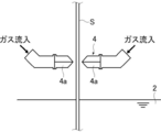
- FIG. 2 is a configuration diagram of the gas expansion device 4 according to the present embodiment.
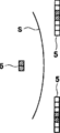
- FIG. 3 is a plan view showing an example of the widthwise arrangement of the electromagnets 5 according to this embodiment.
- the gas expansion device 4 has a pair of nozzles 4a.
- One nozzle 4a faces the front surface of the steel plate S, and the other nozzle 4a faces the back surface of the steel plate S. doing.
- the opening shape of each nozzle 4a is extremely thin and wide in the vertical direction as described in the section "Background Art".
- the electromagnet 5 is installed at least one of above and below the gas expansion device 4. However, since molten zinc may be scattered and accumulated below the gas expansion device 4, it is desirable to install the electromagnet 5 above the gas expansion device 4 as shown in FIG. 1.
- a plurality of electromagnets 5 are arranged along the width direction (plate width direction) of the steel plate S.
- Each of the electromagnets 5 is arranged on both front and back sides of the steel plate S, and is specifically provided to face the front surface or the back surface of the steel plate S. Then, the electromagnet 5 exerts a magnetic force in a direction intersecting with the front surface and the back surface of the steel plate S to suppress the vibration of the steel plate S, and bends and bends when wound around the sink roll 3 and the support roll 7 in the bath. The warp shape of the steel sheet S caused by the return is corrected without contact.
- the arrangement position of the electromagnet 5 in the width direction for example, the arrangement position shown in FIG. 3 can be cited.
- a large number of electromagnets 5 are arranged side by side in the plate width direction, and these electromagnets 5 can be selectively used according to the plate width of the steel plate S and the warp shape in the plate width direction.
- the electromagnet 5 electromagnet 5 with hatching in FIG. 3
- the warp shape of the steel plate S can be adjusted. It is possible.
- a sensor for measuring the distance (spacing) between the steel plate S and the electromagnet 5 or a shape measuring device for the steel plate S may be installed near the electromagnet 5.
- the alloying furnace 8, the heat retaining zone 9 and the cooling zone 10 are for controlling the alloying degree of the plating film by adjusting these temperature conditions appropriately.
- the heating system of the alloying furnace 8 is preferably an induction heating system. This is because the induction heating type can realize uniform heating in the width direction without being affected by the emissivity of the steel sheet surface unlike the gas heating type.
- the adhesion amount meter 11 is a device that measures the amount of plating adhesion on each of the front surface and the back surface of the steel plate S without contact. Further, the deposition amount meter 11 according to the present embodiment can measure the plating deposition amount on each of the front surface and the back surface of the steel plate S at each of a plurality of measurement points on the steel plate S set along the plate width direction. It is possible. That is, the deposition amount meter 11 according to the present embodiment can measure the widthwise distribution of the plating deposition amount on each of the front surface and the back surface of the steel plate S.
- the number and positions of measurement points of the amount of plating adhered are not particularly limited, but it is preferable that the both end positions and the central position of the steel plate S in the plate width direction are included, and the intermediate position between each end position and the central position. More preferably, the position is further included.
- the alloying degree measuring device 12 measures the iron content in the plating film, that is, the alloying degree.
- the alloying degree measuring device 12 does not necessarily need to be able to measure the alloying degree distribution in the width direction.
- the steel plate S is continuously drawn into the plating bath 2, and the sink roll 3 in the plating bath 2 changes the direction of the steel plate S to pull it up from the plating bath 2. Then, wiping gas is sprayed from the nozzle 4a of the gas expansion device 4 toward the steel plate S pulled up from the plating bath 2. Thereby, the amount of plating adhered on each of the front surface and the back surface of the steel plate S is adjusted.
- the steel plate S that has passed through the sink roll 3 is supported by the support roll 6 outside the bath and the support roll 7 inside the bath. Further, the steel plate S receives magnetic force from the plurality of electromagnets 5 above the gas expansion device 4 to prevent vibration and correct the warped shape.
- the steel sheet S with the adjusted amount of plating is heated to a temperature required for alloying in the alloying furnace 8, kept at an appropriate temperature in the heat retaining zone 9, and then cooled in the cooling zone 10.
- a desired degree of alloying can be obtained.
- the plating film is formed on the front and back surfaces of the steel plate S by the above procedure. Then, on the downstream side of the cooling zone 10, the amount of plating applied on each of the front surface and the back surface of the steel sheet S is measured by the adhesion amount meter 11.
- the adhesion amount meter 11 measures the plating adhesion amount at each of a plurality of measurement points set along the plate width direction. As a result, the distribution in the width direction of the coating adhesion amount on each of the front surface and the back surface of the steel plate S is measured.
- the alloying degree of the steel sheet S is measured by the alloying degree measuring device 12. Then, the respective measured values of the coating adhesion amount and the alloying degree are sent to the control computer 16, and the electromagnet 5, the alloying furnace 8 and the gas expansion device 4 are controlled based on these measured values.
- the gas expansion device 4 is adjusted so that the coating amount of plating at each measurement point of the steel plate S becomes an appropriate amount.
- a known adjustment method may be used, for example, the pressure and flow rate of the wiping gas may be adjusted.
- the control value of the output of the gas expansion device 4 is determined according to the adjustment content, and when the control value is sent to the nozzle control device 15, the output of the gas expansion device 4 is controlled by the command of the nozzle control device 15. ..
- the current of each of the plurality of electromagnets 5 is reduced so as to reduce the difference in the plating adhesion amount between the front surface and the back surface of the steel plate S. Control the value.
- the current value of each of the plurality of electromagnets 5 is set so that the difference in the plating adhesion amount becomes zero.
- Feedback control Particularly, in the present embodiment, each current value is feedback-controlled so that the above difference becomes zero at all of the plurality of measurement points.
- the control value of the current value thus obtained is sent to the electromagnet control device 13, and the output of each electromagnet 5 is controlled by the command of the electromagnet control device 13.
- the output of the alloying furnace 8 is controlled so that the desired alloying degree value can be obtained based on the actually measured alloying degree data sent to the control computer 16.
- a known method may be used as the output control method, and for example, the method described in Japanese Patent Application Laid-Open No. 8-269669 may be used.
- the output control value of the alloying furnace 8 is sent to the alloying controller 14, and the output of the alloying furnace 8 is controlled by the command of the alloying controller 14.
- the control of the alloying treatment may be performed not only on the alloying furnace 8 but also on the heat retaining zone 9 and the cooling zone 10.
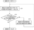
- FIG. 4 is a diagram showing an example of a processing flow of the plating adhesion amount control in the present invention.
- the line control device 17 sends the target values of the plating deposition amount and the alloying degree to the control computer 16.
- the initial condition operating condition before control
- the processing flow of the plating deposition amount control starts in a linked manner.
- the coating weight control first, the coating weight is measured by the coating weight meter 11, and the actual measurement data showing the distribution of the coating weights on the front surface and the back surface of the steel plate S is obtained (ST1 in FIG. 4). Then, it is determined whether or not the difference in the amount of plating adhered between the front surface and the back surface of the steel sheet S is zero at at least one of the measurement points set in the steel sheet S in the plate width direction. (ST2 in FIG. 4).
- the current value of each of the plurality of electromagnets 5 is controlled to correct the shape of the steel sheet S (ST3 in FIG. 4). ..
- step ST3 of FIG. 4 when there is a local difference in the coating amount between the front surface and the back surface of the steel plate S in the plate width direction, the plating at that position is performed.
- the warp shape of the steel sheet S after straightening is adjusted so that the difference in the adhesion amount becomes zero. For example, when the amount of plating on the back surface is larger than the amount of plating on the front surface of the steel plate S at a certain measurement point in the plate width direction, the back surface of the measurement point is brought closer to the tip of the nozzle 4a of the gas expansion device 4. In this way, the shape of the steel plate S after straightening is adjusted.
- the amount of plating adhered on the back surface of the steel sheet S decreases, while the amount of plating adhered on the front surface increases, so that the difference in the amount of plating adhesion approaches zero.
- the above-mentioned steps ST1 to ST3 are performed. repeat. That is, the output of each of the plurality of electromagnets 5 is feedback-controlled, and is repeatedly controlled until the shape of the straightened steel plate S is adjusted so that the difference in the plating adhesion amount at at least one or more measurement points becomes zero. To be done.
- the output control of the gas expansion device 4 may be performed in accordance with the output control of the electromagnet 5 to adjust the plating adhesion amount (strictly, the scraping amount) on each of the front surface and the back surface of the steel plate S.
- the measured alloying degree may be obtained, the output of the alloying furnace 8 may be controlled based on the obtained alloying degree, and the alloying degree of the plating film may be adjusted to an appropriate value. ..
- the plating deposition amount between the front surface and the back surface of the steel plate S is controlled by controlling the current value of each of the plurality of electromagnets 5. Can be reduced. It should be noted that it is sufficient that the difference between the amounts of adhered plating between the front surface and the back surface of the steel sheet S is zero, and the amount of adhered plating on each surface is not necessarily uniform in the plate width direction.
- the hot-dip galvanized steel sheet produced according to the present invention has a uniform coating amount between the front surface and the back surface of the steel sheet, so that unevenness in the coating amount is suppressed, and a plated steel sheet of good quality is obtained. .. Further, since the unevenness of the amount of plating adhered is suppressed, it is possible to suppress the use of excess molten metal and thereby reduce the amount of molten metal used.
- a plurality of measurement points set in the plate width direction are set so that the difference in the plating adhesion amount between the front surface and the back surface of the steel sheet becomes zero.
- the current value of each of the electromagnets was controlled to adjust the shape of the steel sheet after straightening. Specifically, the distance between the tip of the nozzle of the gas expansion device and the back surface of the straightened steel plate (nozzle-steel plate distance) was adjusted as shown in Table 1 below.
- Table 1 shows a value obtained by subtracting the plating adhesion amount on the back surface from the plating adhesion amount on the front surface as a difference in the plating adhesion amount at each measurement location.
- the steel plate shape was flattened without correction.
- the difference between the nozzle-steel plate spacing and the coating adhesion amount in the comparative example is as shown in Table 1 above.
- the measurement points in the plate width direction are the one end position in the plate width direction, the intermediate position between the one end position and the central position (one end side intermediate position), the central position, and the intermediate position between the other end position and the central position. (The intermediate position on the other end side) and the other end position are five positions.
Landscapes
- Chemical & Material Sciences (AREA)
- Chemical Kinetics & Catalysis (AREA)
- Engineering & Computer Science (AREA)
- Materials Engineering (AREA)
- Mechanical Engineering (AREA)
- Metallurgy (AREA)
- Organic Chemistry (AREA)
- Coating With Molten Metal (AREA)
Abstract
溶融金属めっき鋼板の表面と裏面におけるめっき付着量のばらつきを低減することが可能な溶融金属めっき鋼板の製造方法及び製造装置を提供する。 本発明の溶融金属めっき鋼板の製造方法及び製造装置では、気体絞り装置4の上方及び下方の少なくとも一方の位置にて鋼板Sの幅方向に沿って鋼板Sの表裏両側に配置された複数の電磁石5により、鋼板Sの表面及び裏面と交わる方向に磁力を作用させて、鋼板Sの反り形状を非接触で矯正し、めっき浴2の下流側に設置された付着量計11により、鋼板Sの表面及び裏面の各々のめっき付着量を測定し、鋼板Sの表面及び裏面の間のめっき付着量の差を低減させるように、複数の電磁石5の各々の電流値を制御して矯正後の鋼板Sの形状を調整する。
Description
本発明は、溶融金属めっき鋼板の製造方法及び製造装置に関するものであり、特に、溶融金属めっき鋼板の表面と裏面におけるめっき付着量のばらつきを低減するための技術に関する。
溶融金属めっき鋼板の製造方法としては、例えば図5に図示の装置を用いる方法が一般的である。この方法は、溶融金属のめっき浴2中に連続的に引き込んだ鋼板Sをめっき浴2から上方に引き上げ、気体絞り装置4から噴射される高圧ガス(ワイピングガス)によりめっき付着量を調整した後、合金化炉8にて鋼板Sを加熱して、めっき皮膜を構成する金属と鋼板Sの鉄とを合金化させるものである。なお、図5中の溶融金属のめっき浴2中で、鋼板Sがシンクロール3と接触する面を鋼板Sの「表面」と呼び、その反対側の面を「裏面」と呼ぶ。
上記の製造方法において、めっき付着量を制御することは、重要な課題である。従来は、気体絞り装置4のノズル先端と鋼板Sとの間隔、及び噴射されるガス圧力を調整することで、目標の付着量となるようにめっき付着量を調整していた。
しかし、めっき付着量調整部分での鋼板Sの形状は平坦ではなく、C反りと呼ばれる鋼板Sの幅方向(以下、板幅方向とも言う)に円弧状に湾曲した形状となるのが一般的である。このような反りが鋼板Sに形成されている場合、鋼板Sと気体絞り装置4のノズル先端との間隔が、板幅方向における位置に応じて変化する。そのため、鋼板Sにおいてノズルから離れた部分ではワイピングガスによる掻き落とし力が不足してめっき付着量が多くなり、ノズルに近い部分では逆にめっき付着量が少なくなり、板幅方向においてめっき付着量のばらつきが生じる。
そこで、溶融金属めっき鋼板の一般的な製造装置では、気体絞り装置4の近傍に電磁石を設け、その磁力により鋼板の形状を平坦に矯正することにより、めっき付着量の均一化を図っている。
しかしながら、一般的に、気体絞り装置4のノズル形状は、ノズル幅(詳しくは、板幅方向におけるノズル開口の長さ)が2~2.5m(2000~2500mm)であり、ノズル隙間(詳しくは、鉛直方向におけるノズル開口の長さ)が0.6~1.2mmと極めて薄く幅広な形状となっている。このような形状のノズルにおいて、ノズル隙間をノズルの幅方向に全く均一に製造することは容易ではなく、また、ノズルの幅方向に全く均一なガス圧力で全く均一な流量のワイピングガスを提供することも容易ではない。つまり、ワイピング力を板幅方向に完全に均一にすることは、極めて困難である。
したがって、電磁石5によって矯正する鋼板Sの形状については、完全なフラット形状(平坦形状)とするのではなく、めっき付着量等を実測し、その実測値に基づいて矯正後の鋼板形状を調整する必要がある。
一方、溶融金属めっき鋼板の製造過程において電磁石5による形状矯正を実施する際に、測定された情報に基づき、板幅方向における合金化度(めっき皮膜中の平均Fe濃度)の分布が均一になるように電磁石5の電流値を制御することが知られている(例えば、特許文献1参照)。
特許文献1に記載の方法では、板幅方向に沿って並べて配置された複数の電磁石5を選択的に使用することで、鋼板Sの幅方向の反り形状を矯正することになっている(特許文献1の段落0043参照)。具体的には、選択された電磁石5について電流値を補正したり、あるいは位置(鋼板Sからの距離)を変更したりすることで出力が制御される(特許文献1の段落0050参照)。
しかし、特許文献1に記載の方法は、板幅方向における合金化度の分布を均一にすることを目的としており、必ずしも、板幅方向においてめっき付着量を均一化するものではない(特許文献1の段落0022参照)。また、前述したように、気体絞り装置4のワイピング力が板幅方向に完全に均一ではない。このため、板幅方向におけるワイピング力の分布が、鋼板Sの表面及び裏面の間で変わってしまう可能性がある。その場合には、鋼板Sの表面と裏面との間でめっき付着量が異なることになる。
さらに、特許文献1に記載の方法において鋼板Sの表面でのめっき付着量を均一にするために、電磁石5を用いて鋼板Sの反り形状を矯正すると、鋼板Sの裏面の形状も同時に矯正されることになる。その場合には、鋼板Sの裏面でのめっき付着量分布の均一性が崩れてしまう。
さらにまた、特許文献1に記載の方法では、合金化度の分布が許容範囲内になるまで電磁石5による形状矯正を繰り返し実施することになっている。ただし、形状矯正を繰り返し実施したとしても、必ずしも、鋼板Sの表面及び裏面の各々でめっき付着量が均一になるように収束するとは限らない。
そこで、本発明は、上記の事情に鑑みてなされたものであり、以下に示す目的を解決することを課題とする。
具体的には、本発明は、上記従来技術の問題点を解決し、溶融金属めっき鋼板の表面と裏面におけるめっき付着量のばらつきを低減することが可能な溶融金属めっき鋼板の製造方法及び製造装置を提供することを目的とする。
具体的には、本発明は、上記従来技術の問題点を解決し、溶融金属めっき鋼板の表面と裏面におけるめっき付着量のばらつきを低減することが可能な溶融金属めっき鋼板の製造方法及び製造装置を提供することを目的とする。
上記の目的を達成するために、本発明の溶融金属めっき鋼板の製造方法は、鋼板を溶融金属のめっき浴に連続的に引き込み、めっき浴中の方向転換装置により方向転換させてめっき浴から引き上げ、気体絞り装置により鋼板のめっき付着量を調整する溶融金属めっき鋼板の製造方法であって、気体絞り装置の上方及び下方の少なくとも一方の位置にて鋼板の幅方向に沿って鋼板の表裏両側に配置された複数の電磁石により、鋼板の表面及び裏面と交わる方向に磁力を作用させて、鋼板の反り形状を非接触で矯正し、めっき浴の下流側に設置された付着量計により、鋼板の表面及び裏面の各々のめっき付着量を測定し、鋼板の表面及び裏面の間のめっき付着量の差を低減させるように、複数の電磁石の各々の電流値を制御して矯正後の鋼板の形状を調整することを特徴とする。
上記の方法によれば、鋼板の表面及び裏面の間でめっき付着量に差が生じた場合に、その差を低減するように鋼板の形状を矯正することができる。これにより、良好な品質の溶融金属めっき鋼板を製造することが可能となる。
また、上述した本発明の溶融金属めっき鋼板の製造方法において、付着量計は、幅方向に沿って設定された鋼板における複数の測定箇所のそれぞれにおいて、鋼板の表面及び裏面の各々のめっき付着量を測定し、複数の測定箇所のうちの少なくとも1つ以上において、差がゼロになるように、複数の電磁石の各々の電流値を制御して矯正後の鋼板の形状を調整するとよい。
上記の方法によれば、鋼板の表面及び裏面の間でめっき付着量に差が生じた箇所が板幅方向において局所的に存在している場合に、その箇所でのめっき付着量の差をなくすように鋼板形状の矯正が可能となる。例えば、板幅方向における或る測定箇所で鋼板の表面のめっき付着量よりも裏面のめっき付着量が多くなった場合、その箇所にて鋼板の裏面を気体絞り装置に近付けるように鋼板の形状を矯正する。これにより、上記箇所における裏面のめっき付着量が減少し、その箇所での表面のめっき付着量が増加するので、表面と裏面との間の付着量差をゼロに近付けることが可能となる。
上記の方法によれば、鋼板の表面及び裏面の間でめっき付着量に差が生じた箇所が板幅方向において局所的に存在している場合に、その箇所でのめっき付着量の差をなくすように鋼板形状の矯正が可能となる。例えば、板幅方向における或る測定箇所で鋼板の表面のめっき付着量よりも裏面のめっき付着量が多くなった場合、その箇所にて鋼板の裏面を気体絞り装置に近付けるように鋼板の形状を矯正する。これにより、上記箇所における裏面のめっき付着量が減少し、その箇所での表面のめっき付着量が増加するので、表面と裏面との間の付着量差をゼロに近付けることが可能となる。
また、上記の方法において、差がゼロになるように、複数の電磁石の各々の電流値をフィードバック制御してもよい。これにより、表面と裏面との間の付着量差がゼロになるまで鋼板の形状矯正を繰り返すことができる。
また、本発明の溶融金属めっき鋼板の製造方法において、矯正後の鋼板の形状を調整することにより、気体絞り装置が備えるノズルの先端と鋼板との間隔を変更するとよい。
また、前述した課題を解決するため、本発明の溶融金属めっき鋼板の製造装置は、溶融金属のめっき浴と、めっき浴に連続的に引き込まれる鋼板を、めっき浴から引き上げるためにめっき浴中で方向転換させる方向転換装置と、鋼板のめっき付着量を調整する気体絞り装置と、鋼板の表面及び裏面と交わる方向に磁力を発生させて鋼板の反り形状を非接触で矯正するために、気体絞り装置の上方及び下方の少なくとも一方の位置にて鋼板の幅方向に沿って鋼板の表裏両側に配置された複数の電磁石と、めっき浴の下流側にて、鋼板の表面及び裏面の各々のめっき付着量を測定する付着量計と、鋼板の表面及び裏面の間のめっき付着量の差を低減させるように矯正後の鋼板の形状を調整するために、複数の電磁石の各々の電流値を制御する電磁石制御装置と、を有することを特徴とする。
本発明によれば、溶融金属めっき鋼板の表面と裏面におけるめっき付着量のばらつきを低減し、良好な品質となった(厳密には、付着量ムラが抑えられた)溶融金属めっき鋼板を製造することが可能である。
本発明の一実施形態(以下、本実施形態)に係る溶融金属めっき鋼板の製造装置、及び、その装置を用いた溶融金属めっき鋼板の製造方法について、添付の図面を参照しながら以下に詳細に説明する。
なお、以下に説明する実施形態は、本発明の好適な一実施形態ではあるものの、あくまでも一例に過ぎず、本発明を限定するものではない。すなわち、本発明は、その趣旨を逸脱することなく、変更、改良され得るとともに、本発明には、その等価物が含まれることは勿論である。
また、以下では、溶融金属の一例として溶融亜鉛を用いて溶融金属めっき鋼板(主として、溶融亜鉛めっき鋼板)を製造するケースを想定して説明することとする。ただし、溶融金属については、溶融亜鉛に限られず、他にも溶融スズ、溶融アルミニウム、及び溶融鉛等が挙げられる。
また、以下の説明において、「下流側」とは、溶融金属めっき鋼板の製造過程における鋼板Sの搬送方向において、より後段側(分かり易くは、鋼板の搬送経路において終着地点により近い側)を意味する。
また、以下の説明において、「ゼロ」には、厳密にはゼロではないものの、その誤差が本発明の属する技術分野における許容範囲内(めっき付着量については、±1.0g/m2未満)にある場合も含まれることとする。
<溶融金属めっき鋼板製造装置の構成例について>
本実施形態に係る溶融金属めっき鋼板の製造装置(具体的は、溶融亜鉛めっき鋼板の製造装置であり、以下では製造装置100と言う)の構成について、図1を参照しながら説明する。図1は、製造装置100の構成図である。
本実施形態に係る溶融金属めっき鋼板の製造装置(具体的は、溶融亜鉛めっき鋼板の製造装置であり、以下では製造装置100と言う)の構成について、図1を参照しながら説明する。図1は、製造装置100の構成図である。
製造装置100は、図1に示すように、ストリップ状の鋼板Sに付着させる溶融亜鉛のめっき浴2を保持するめっき槽1、めっき浴2から引き上げられた鋼板Sに付着した溶融亜鉛めっき量(めっき付着量)を調整する気体絞り装置4、電磁石5、及び、浴外の支持ロール6を備えている。また、支持ロール6の下流側には、めっき皮膜を合金化させる合金化炉8、保熱帯9、及び冷却帯10が設けられている。さらに下流側の位置には、めっき皮膜の計測機器としての付着量計11及び合金化度測定装置12が設けられている。
また、製造装置100は、装置各部を制御する制御装置として、電磁石5を制御する電磁石制御装置13、合金化炉8を制御する合金化制御装置14、及び、気体絞り装置4のノズル4aを制御するノズル制御装置15を備え、これらの制御装置を統括する制御用計算機16及びライン制御装置17を更に備えている。
鋼板Sは、めっき槽1の内部にあるめっき浴2に連続的に引き込まれ、めっき浴2に浸漬される。めっき浴2の中には、図1に示すように、鋼板Sを巻き掛けて方向転換させる方向転換装置が設けられている。この方向転換装置としては、シンクロール3が一般的である。
また、方向転換された鋼板Sをめっき浴2中で支持する浴中の支持ロール7を備えてもよい。ただし、浴中の支持ロール7は、鋼板Sの振動抑制及び反り形状の矯正には効果があるものの、めっき浴2中のドロスを巻き込んで鋼板Sとの間に噛み込み、いわゆるドロス欠陥を生じさせる場合がある。本発明では、電磁石5により十分に振動抑制及び反り形状の矯正を行うことができるので、浴中の支持ロール7の設置は、必ずしも要しない。
気体絞り装置4及び電磁石5は、めっき浴2の浴面と浴外の支持ロール6との間に設けられる。本実施形態における気体絞り装置4及び電磁石5の構成について、図1、図2及び図3を参照しながら説明する。図2は、本実施形態に係る気体絞り装置4の構成図である。図3は、本実施形態に係る電磁石5の幅方向配置の一例を示す平面図である。
気体絞り装置4は、図2に示すように、対をなすノズル4aを有しており、一方のノズル4aは、鋼板Sの表面に対向し、他方のノズル4aは、鋼板Sの裏面に対向している。また、各ノズル4aの開口形状は、「背景技術」の項で説明したように、上下方向に極めて薄く、且つ幅広な形状となっている。
電磁石5は、気体絞り装置4の上方及び下方のうちの少なくとも一方に設置される。ただし、気体絞り装置4の下方は、溶融亜鉛が飛散して堆積する虞があるため、図1に示すように、気体絞り装置4の上方に電磁石5を設置するのが望ましい。
電磁石5は、図3に示すように、鋼板Sの幅方向(板幅方向)に沿って複数配置されている。各々の電磁石5は、鋼板Sの表裏両側に配置されており、具体的には鋼板Sの表面又は裏面に対向して設けられる。そして、電磁石5は、鋼板Sの表面及び裏面と交わる方向に磁力を作用させて、鋼板Sの振動を抑制すると共に、シンクロール3及び浴中の支持ロール7に巻きつけた際の曲げ及び曲げ戻しによって生じる鋼板Sの反り形状を非接触で矯正する。
電磁石5の幅方向の配置位置については、例えば、図3に図示の配置位置が一例として挙げられる。このように板幅方向に電磁石5を多数並べて配置し、これらの電磁石5を、鋼板Sの板幅及び板幅方向の反り形状に応じて選択的に使用することができる。具体的に説明すると、例えば、図3に図示の選択パターンにて電磁石5(図3中、ハッチングが施された電磁石5)を選択して使用すれば、鋼板Sの反り形状を調整することが可能である。
なお、電磁石5の近傍には、鋼板Sと電磁石5との距離(間隔)を測定するセンサ、あるいは鋼板Sの形状測定装置等を設置してもよい。
合金化炉8、保熱帯9及び冷却帯10は、これらの温度条件を適切に調整することにより、めっき皮膜の合金化度を制御するものである。板幅方向の合金化度を均一とするためには、上記3つの装置(合金化炉8、保熱帯9及び冷却帯10)における板幅方向の温度条件が均一であることが望ましい。そのため、合金化炉8の加熱方式は、誘導加熱式とすることが好ましい。誘導加熱式であれば、ガス加熱式のように鋼板表面の放射率の影響を受けることがなく、幅方向に均一な加熱が実現できるためである。
付着量計11は、鋼板Sの表面及び裏面の各々のめっき付着量を非接触で測定する装置である。また、本実施形態に係る付着量計11は、板幅方向に沿って設定された鋼板Sにおける複数の測定箇所のそれぞれにおいて、鋼板Sの表面及び裏面の各々のめっき付着量を測定することが可能である。つまり、本実施形態に係る付着量計11は、鋼板Sの表面及び裏面の各々におけるめっき付着量の幅方向分布を測定することができる。
なお、めっき付着量の測定箇所の数及び位置については、特に限定されないが、板幅方向における鋼板Sの両端位置及び中央位置が含まれているのが好ましく、各端位置と中央位置との中間位置が更に含まれているとより好ましい。
合金化度測定装置12は、めっき皮膜中の鉄含有率、すなわち合金化度を測定するものである。なお、本発明において、合金化度測定装置12は、必ずしも幅方向の合金化度分布を測定できるものでなくてもよい。
次に、以上のように構成された製造装置100を用いた溶融金属めっき鋼板の製造方法について説明する。先ず、図1に示すように、鋼板Sをめっき浴2に連続的に引き込み、めっき浴2中のシンクロール3により方向転換させてめっき浴2から引き上げる。その後、めっき浴2から引き上げられた鋼板Sに向けて、気体絞り装置4のノズル4aからワイピングガスを吹き付ける。これにより、鋼板Sの表面及び裏面の各々のめっき付着量が調整される。
なお、シンクロール3を通過した鋼板Sは、浴外の支持ロール6及び浴中の支持ロール7により支持される。また、鋼板Sは、気体絞り装置4の上方にて複数の電磁石5から磁力を受けて、振動防止及び反り形状の矯正が図られる。
めっき付着量が調整された鋼板Sは、合金化炉8で合金化に必要な温度まで加熱され、保熱帯9で適正な温度で保たれた後、冷却帯10で冷却される。ここで、合金化炉8、保熱帯9及び冷却帯10の各々において温度条件を調整することにより、所望の合金化度が得られるようになる。
以上までの手順により、鋼板Sの表面及び裏面にめっき皮膜が形成される。そして、冷却帯10の下流側で、付着量計11により鋼板Sの表面及び裏面の各々のめっき付着量が測定される。ここで、付着量計11は、板幅方向に沿って設定された複数の測定箇所の各々においてめっき付着量を測定する。この結果、鋼板Sの表面及び裏面の各々におけるめっき付着量の幅方向分布が測定される。
さらに、合金化度測定装置12により鋼板Sの合金化度が測定される。そして、めっき付着量及び合金化度のそれぞれの測定値は、制御用計算機16へ送られ、これらの測定値に基づいて電磁石5、合金化炉8及び気体絞り装置4の制御が行われる。
詳しく説明すると、先ず、制御用計算機16に送られためっき付着量の実測データに基づき、鋼板Sの各測定箇所におけるめっき付着量が適正量となるように気体絞り装置4を調整する。具体的な調整としては、公知の調整方法を用いればよく、例えば、ワイピングガスの圧力及び流量等を調整すればよい。そして、調整内容に応じて気体絞り装置4の出力の制御値を決定し、その制御値をノズル制御装置15へ送ると、ノズル制御装置15の指令により、気体絞り装置4の出力が制御される。
次に、制御用計算機16に送られためっき付着量の幅方向分布データに基づき、鋼板Sの表面及び裏面の間のめっき付着量の差を低減させるように、複数の電磁石5の各々の電流値を制御する。
より具体的には、板幅方向において鋼板Sに設定された複数の測定箇所のうちの少なくとも1つ以上において、めっき付着量の差がゼロになるように複数の電磁石5の各々の電流値をフィードバック制御する。特に、本実施形態では、複数の測定箇所のすべてにおいて上記の差がゼロになるように各電流値をフィードバック制御する。このようにして得られた電流値の制御値が電磁石制御装置13へ送られて、電磁石制御装置13の指令により、各電磁石5の出力が制御される。
そして、各電磁石5の出力が制御されると、矯正後の鋼板Sの反り形状が調整され、これにより、気体絞り装置4が有するノズル4aの先端と鋼板Sとの間隔(以下、ノズル-鋼板の間隔と言う)が変更される。
なお、各電磁石5の電流値をフィードバック制御する代わりに、ノズル-鋼板の間隔と、鋼板Sの表面及び裏面の各々のめっき付着量と、の対応関係を予めモデルとして数式化しておくとよい。このモデル式を用いて、めっき付着量の差がゼロとなるような鋼板形状(具体的には、ノズル-鋼板の間隔)を特定し、特定した形状に基づいて各電磁石5の電流値を制御してもよい。
次に、制御用計算機16に送られた合金化度の実測データに基づき、所望の合金化度の値が得られるように合金化炉8の出力を制御する。出力制御の方法については、公知の方法を用いればよく、例えば特開平8-269669号公報に記載の方法を用いることができる。そして、合金化炉8の出力制御値を合金化制御装置14へ送り、合金化制御装置14の指令により合金化炉8の出力が制御される。なお、合金化処理の制御については、合金化炉8のみではなく、保熱帯9及び冷却帯10に対して行ってもよい。
以下、図4を参照しながら、上述しためっき付着量制御の流れ、特に電磁石5の出力制御によるめっき付着量制御の処理フローについて説明する。図4は、本発明におけるめっき付着量制御の処理フローの一例を示す図である。
めっき付着量制御の処理フローが開始されるにあたり、ライン制御装置17からめっき付着量及び合金化度の目標値が制御用計算機16へ送られる。これにより、製造装置100の各部が初期条件(制御前の操業条件)に従って運転を開始し、これに連動する形で、めっき付着量制御の処理フローがスタートする。
めっき付着量制御では、先ず、付着量計11によるめっき付着量の測定を実施し、鋼板Sの表面及び裏面の付着量分布を示す実測データを入手する(図4のST1)。そして、板幅方向において鋼板Sに複数設定された測定箇所のうち、少なくとも一つ以上の測定箇所で、鋼板Sの表面と裏面との間におけるめっき付着量の差がゼロであるかを判定する(図4のST2)。
上記の判定において、少なくとも一つ以上の測定箇所においてめっき付着量の差がゼロではない場合、複数の電磁石5の各々の電流値を制御して鋼板Sの形状を矯正する(図4のST3)。
つまり、図4のステップST3では、鋼板Sの表面と裏面との間でめっき付着量に差が生じている箇所が板幅方向において局所的に存在している場合には、その箇所でのめっき付着量の差をゼロとするように矯正後の鋼板Sの反り形状を調整する。例えば、板幅方向における或る測定箇所で鋼板Sの表面のめっき付着量よりも裏面のめっき付着量の方が多かった場合、当該測定箇所の裏面を気体絞り装置4のノズル4aの先端に近付けるように矯正後の鋼板Sの形状を調整する。これにより、上記の測定箇所では、鋼板Sの裏面でのめっき付着量が減少する一方で、表面でのめっき付着量が増加するので、めっき付着量の差がゼロに近付くようになる。
そして、板幅方向における複数の測定箇所の少なくとも一つ以上の測定箇所において、鋼板Sの表面と裏面との間のめっき付着量の差がゼロではない場合には、上述したステップST1~ST3を繰り返す。つまり、複数の電磁石5の各々の出力は、フィードバック制御され、少なくとも一つ以上の測定箇所でのめっき付着量の差がゼロとなるように矯正後の鋼板Sの形状が調整されるまで繰り返し制御される。
なお、電磁石5の出力制御に合わせて、気体絞り装置4の出力制御を実施して鋼板Sの表面及び裏面の各々におけるめっき付着量(厳密には、掻き落とし量)を調整してもよい。
また、合金化度の測定値を入手し、入手した合金化度の値に基づいて合金化炉8の出力を制御し、めっき皮膜の合金化度を適切値となるように調整してもよい。
以上までに説明してきたように、本実施形態に係るめっき付着量制御の処理フローでは、複数の電磁石5の各々の電流値を制御することにより、鋼板Sの表面及び裏面の間におけるめっき付着量のばらつき(ムラ)を低減することが可能となる。なお、鋼板Sの表面及び裏面の間でめっき付着量の差がゼロとなっていればよく、各面におけるめっき付着量が必ずしも板幅方向に均一でなくてもよい。
そして、本発明により製造された溶融金属めっき鋼板は、鋼板の表面と裏面との間でめっき付着量が均一であるため、付着量のムラが抑えられており、良好な品質のめっき鋼板となる。また、めっき付着量ムラが抑えられることで余剰な溶融金属の使用を抑制し、以て溶融金属の使用量を削減することが可能となる。
以下、下記の実施例に基づいて本発明をより詳細に説明する。なお、下記の実施例に示す処理内容及び処理手順等については、本発明の趣旨を逸脱しない限り適宜変更することができる。したがって、本発明の範囲は、下記の実施例によって限定的に解釈されるべきものではない。
〔実施例及び比較例について〕
実施例では、図4に図示の処理フローに従い、板幅方向に設定された複数の測定箇所の各々において鋼板の表面と裏面との間のめっき付着量の差がゼロとなるように、複数の電磁石の各々の電流値を制御して矯正後の鋼板形状を調整した。具体的には、気体絞り装置が有するノズルの先端と矯正後の鋼板の裏面との間隔(ノズル-鋼板の間隔)を下記の表1のように調整した。
また、表1には、各測定箇所におけるめっき付着量の差として、表面のめっき付着量から裏面のめっき付着量を差し引いた値を示した。
実施例では、図4に図示の処理フローに従い、板幅方向に設定された複数の測定箇所の各々において鋼板の表面と裏面との間のめっき付着量の差がゼロとなるように、複数の電磁石の各々の電流値を制御して矯正後の鋼板形状を調整した。具体的には、気体絞り装置が有するノズルの先端と矯正後の鋼板の裏面との間隔(ノズル-鋼板の間隔)を下記の表1のように調整した。
また、表1には、各測定箇所におけるめっき付着量の差として、表面のめっき付着量から裏面のめっき付着量を差し引いた値を示した。
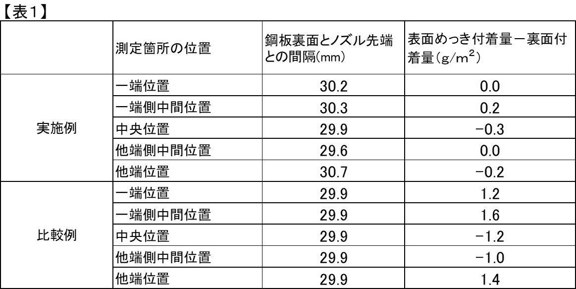
一方、比較例では、鋼板形状を矯正せずに平坦形状(フラット形状)とした。比較例におけるノズル-鋼板の間隔及びめっき付着量の差は、上記の表1に示す通りである。
なお、実施例及び比較例では、板幅方向における測定箇所を板幅方向の一端位置、一端位置と中央位置の中間位置(一端側中間位置)、中央位置、他端位置と中央位置の中間位置(他端側中間位置)、及び他端位置の5箇所とした。
上記の表1に示すように、実施例では、鋼板形状を電磁石によって矯正することにより、鋼板の表面と裏面との間のめっき付着量の差が比較例に比べて小さくなっている(ゼロにより近付いている)。
以上に説明した実施例は、いずれも本発明の構成を充足するものであるから、本発明の効果は明らかである。
1 めっき槽
2 めっき浴
3 シンクロール(方向転換装置)
4 気体絞り装置
4a ノズル
5 電磁石
6 浴外支持ロール
7 浴中支持ロール
8 合金化炉
9 保熱帯
10 冷却帯
11 付着量計
12 合金度測定装置
13 電磁石制御装置
14 合金化制御装置
15 ノズル制御装置
16 制御用計算機
17 ライン制御装置
100 製造装置
S 鋼板
2 めっき浴
3 シンクロール(方向転換装置)
4 気体絞り装置
4a ノズル
5 電磁石
6 浴外支持ロール
7 浴中支持ロール
8 合金化炉
9 保熱帯
10 冷却帯
11 付着量計
12 合金度測定装置
13 電磁石制御装置
14 合金化制御装置
15 ノズル制御装置
16 制御用計算機
17 ライン制御装置
100 製造装置
S 鋼板
Claims (5)
- 鋼板を溶融金属のめっき浴に連続的に引き込み、前記めっき浴中の方向転換装置により方向転換させて前記めっき浴から引き上げ、気体絞り装置により前記鋼板のめっき付着量を調整する溶融金属めっき鋼板の製造方法であって、
前記気体絞り装置の上方及び下方の少なくとも一方の位置にて前記鋼板の幅方向に沿って前記鋼板の表裏両側に配置された複数の電磁石により、前記鋼板の表面及び裏面と交わる方向に磁力を作用させて、前記鋼板の反り形状を非接触で矯正し、
前記めっき浴の下流側に設置された付着量計により、前記鋼板の表面及び裏面の各々のめっき付着量を測定し、
前記鋼板の表面及び裏面の間のめっき付着量の差を低減させるように、前記複数の電磁石の各々の電流値を制御して矯正後の前記鋼板の形状を調整することを特徴とする溶融金属めっき鋼板の製造方法。 - 前記付着量計は、前記幅方向に沿って設定された前記鋼板における複数の測定箇所のそれぞれにおいて、前記鋼板の表面及び裏面の各々のめっき付着量を測定し、
前記複数の測定箇所のうちの少なくとも1つ以上において、前記差がゼロになるように、前記複数の電磁石の各々の電流値を制御して矯正後の前記鋼板の形状を調整する請求項1に記載の溶融金属めっき鋼板の製造方法。 - 前記差がゼロになるように、前記複数の電磁石の各々の電流値をフィードバック制御する請求項1又は2に記載の溶融金属めっき鋼板の製造方法。
- 矯正後の前記鋼板の形状を調整することにより、前記気体絞り装置が備えるノズルの先端と前記鋼板との間隔を変更する請求項1乃至3のいずれか一項に記載の溶融金属めっき鋼板の製造方法。
- 溶融金属のめっき浴と、
前記めっき浴に連続的に引き込まれる鋼板を、前記めっき浴から引き上げるために前記めっき浴中で方向転換させる方向転換装置と、
前記鋼板のめっき付着量を調整する気体絞り装置と、
前記鋼板の表面及び裏面と交わる方向に磁力を発生させて前記鋼板の反り形状を非接触で矯正するために、前記気体絞り装置の上方及び下方の少なくとも一方の位置にて前記鋼板の幅方向に沿って前記鋼板の表裏両側に配置された複数の電磁石と、
前記めっき浴の下流側にて、前記鋼板の表面及び裏面の各々のめっき付着量を測定する付着量計と、
前記鋼板の表面及び裏面の間のめっき付着量の差を低減させるように矯正後の前記鋼板の形状を調整するために、前記複数の電磁石の各々の電流値を制御する電磁石制御装置と、を有することを特徴とする溶融金属めっき鋼板の製造装置。
Priority Applications (3)
| Application Number | Priority Date | Filing Date | Title |
|---|---|---|---|
| JP2020501838A JPWO2020121646A1 (ja) | 2018-12-11 | 2019-10-17 | 溶融金属めっき鋼板の製造方法、溶融金属めっき鋼板の製造装置 |
| MX2021006938A MX2021006938A (es) | 2018-12-11 | 2019-10-17 | Metodo para fabricar chapa de acero revestida con metal por inmersion en caliente y aparato para fabricar chapa de acero revestida con metal por inmersion en caliente. |
| CN201980079447.3A CN113166909A (zh) | 2018-12-11 | 2019-10-17 | 熔融金属镀覆钢板的制造方法、熔融金属镀覆钢板的制造装置 |
Applications Claiming Priority (2)
| Application Number | Priority Date | Filing Date | Title |
|---|---|---|---|
| JP2018231397 | 2018-12-11 | ||
| JP2018-231397 | 2018-12-11 |
Publications (1)
| Publication Number | Publication Date |
|---|---|
| WO2020121646A1 true WO2020121646A1 (ja) | 2020-06-18 |
Family
ID=71077242
Family Applications (1)
| Application Number | Title | Priority Date | Filing Date |
|---|---|---|---|
| PCT/JP2019/040837 Ceased WO2020121646A1 (ja) | 2018-12-11 | 2019-10-17 | 溶融金属めっき鋼板の製造方法、溶融金属めっき鋼板の製造装置 |
Country Status (4)
| Country | Link |
|---|---|
| JP (1) | JPWO2020121646A1 (ja) |
| CN (1) | CN113166909A (ja) |
| MX (1) | MX2021006938A (ja) |
| WO (1) | WO2020121646A1 (ja) |
Citations (2)
| Publication number | Priority date | Publication date | Assignee | Title |
|---|---|---|---|---|
| JP2004027315A (ja) * | 2002-06-27 | 2004-01-29 | Jfe Steel Kk | 溶融金属めっき鋼板の製造方法および製造装置 |
| WO2013168668A1 (ja) * | 2012-05-10 | 2013-11-14 | 新日鐵住金株式会社 | 鋼板形状制御方法及び鋼板形状制御装置 |
Family Cites Families (3)
| Publication number | Priority date | Publication date | Assignee | Title |
|---|---|---|---|---|
| JP3574204B2 (ja) * | 1995-01-24 | 2004-10-06 | 新日本製鐵株式会社 | 溶融めっき鋼板のめっき付着量制御装置及び方法 |
| CN1163624C (zh) * | 1995-11-10 | 2004-08-25 | 川崎制铁株式会社 | 保持熔融金属的方法与设备 |
| JP5444706B2 (ja) * | 2008-12-18 | 2014-03-19 | Jfeスチール株式会社 | 金属帯の制御方法及び溶融めっき金属帯の製造方法 |
-
2019
- 2019-10-17 CN CN201980079447.3A patent/CN113166909A/zh active Pending
- 2019-10-17 JP JP2020501838A patent/JPWO2020121646A1/ja active Pending
- 2019-10-17 MX MX2021006938A patent/MX2021006938A/es unknown
- 2019-10-17 WO PCT/JP2019/040837 patent/WO2020121646A1/ja not_active Ceased
Patent Citations (2)
| Publication number | Priority date | Publication date | Assignee | Title |
|---|---|---|---|---|
| JP2004027315A (ja) * | 2002-06-27 | 2004-01-29 | Jfe Steel Kk | 溶融金属めっき鋼板の製造方法および製造装置 |
| WO2013168668A1 (ja) * | 2012-05-10 | 2013-11-14 | 新日鐵住金株式会社 | 鋼板形状制御方法及び鋼板形状制御装置 |
Also Published As
| Publication number | Publication date |
|---|---|
| MX2021006938A (es) | 2021-07-15 |
| CN113166909A (zh) | 2021-07-23 |
| JPWO2020121646A1 (ja) | 2021-02-15 |
Similar Documents
| Publication | Publication Date | Title |
|---|---|---|
| CN103597111B (zh) | 钢板形状控制方法以及钢板形状控制装置 | |
| JP6350663B2 (ja) | 鋼帯の冷却方法及び冷却設備 | |
| WO2004003249A1 (ja) | 溶融金属めっき鋼板の製造方法および製造装置 | |
| JP2019525008A (ja) | 金属ストリップの被覆のための方法および被覆装置 | |
| JP5644141B2 (ja) | 金属帯の制振及び位置矯正装置、および該装置を用いた溶融めっき金属帯製造方法 | |
| JP7134591B2 (ja) | 連続溶融亜鉛めっき方法及び連続溶融亜鉛めっき装置 | |
| JP3201260B2 (ja) | 溶融金属めっき鋼板の付着量制御方法 | |
| JP3876810B2 (ja) | 金属帯の制振装置及び金属帯の製造方法 | |
| JPH02254146A (ja) | 誘導加熱装置及び誘導加熱式合金化炉及び合金化方法 | |
| JPWO2020121646A1 (ja) | 溶融金属めっき鋼板の製造方法、溶融金属めっき鋼板の製造装置 | |
| JP5263433B2 (ja) | 金属帯の安定装置および溶融めっき金属帯の製造方法 | |
| JP5223451B2 (ja) | 溶融めっき金属帯の製造方法 | |
| JP5600873B2 (ja) | 溶融めっき鋼帯の製造方法 | |
| JP3755492B2 (ja) | 合金化溶融亜鉛めっき鋼板及びその製造方法 | |
| JP5169089B2 (ja) | 連続溶融金属めっき方法 | |
| JP6648650B2 (ja) | 金属帯の安定装置および溶融めっき金属帯の製造方法 | |
| JP2016169430A (ja) | 溶融亜鉛めっき鋼板の製造方法 | |
| JP2016151032A (ja) | 溶融金属めっき鋼板の製造設備および製造方法 | |
| JP2002275610A (ja) | 金属帯形状制御装置 | |
| WO2017110667A1 (ja) | 金属帯の安定装置および溶融めっき金属帯の製造方法 | |
| JP3114572B2 (ja) | 合金化溶融亜鉛鍍金鋼板の合金化制御方法 | |
| JP3535131B2 (ja) | 溶融めっき鋼帯の製造方法 | |
| JP2015160959A (ja) | 金属帯の非接触制御装置および溶融めっき金属帯の製造方法 | |
| JP2789946B2 (ja) | 合金化溶融亜鉛めっき鋼板の製造方法 | |
| JPH04329857A (ja) | 溶融合金化亜鉛めっき鋼帯の合金化制御方法 |
Legal Events
| Date | Code | Title | Description |
|---|---|---|---|
| ENP | Entry into the national phase |
Ref document number: 2020501838 Country of ref document: JP Kind code of ref document: A |
|
| 121 | Ep: the epo has been informed by wipo that ep was designated in this application |
Ref document number: 19895704 Country of ref document: EP Kind code of ref document: A1 |
|
| NENP | Non-entry into the national phase |
Ref country code: DE |
|
| 122 | Ep: pct application non-entry in european phase |
Ref document number: 19895704 Country of ref document: EP Kind code of ref document: A1 |