WO2020121635A1 - 内燃機関のバルブタイミング制御装置 - Google Patents
内燃機関のバルブタイミング制御装置 Download PDFInfo
- Publication number
- WO2020121635A1 WO2020121635A1 PCT/JP2019/039930 JP2019039930W WO2020121635A1 WO 2020121635 A1 WO2020121635 A1 WO 2020121635A1 JP 2019039930 W JP2019039930 W JP 2019039930W WO 2020121635 A1 WO2020121635 A1 WO 2020121635A1
- Authority
- WO
- WIPO (PCT)
- Prior art keywords
- vane
- recess
- control device
- valve timing
- timing control
- Prior art date
- Legal status (The legal status is an assumption and is not a legal conclusion. Google has not performed a legal analysis and makes no representation as to the accuracy of the status listed.)
- Ceased
Links
Images






Classifications
-
- F—MECHANICAL ENGINEERING; LIGHTING; HEATING; WEAPONS; BLASTING
- F01—MACHINES OR ENGINES IN GENERAL; ENGINE PLANTS IN GENERAL; STEAM ENGINES
- F01L—CYCLICALLY OPERATING VALVES FOR MACHINES OR ENGINES
- F01L1/00—Valve-gear or valve arrangements, e.g. lift-valve gear
- F01L1/34—Valve-gear or valve arrangements, e.g. lift-valve gear characterised by the provision of means for changing the timing of the valves without changing the duration of opening and without affecting the magnitude of the valve lift
- F01L1/344—Valve-gear or valve arrangements, e.g. lift-valve gear characterised by the provision of means for changing the timing of the valves without changing the duration of opening and without affecting the magnitude of the valve lift changing the angular relationship between crankshaft and camshaft, e.g. using helicoidal gear
- F01L1/356—Valve-gear or valve arrangements, e.g. lift-valve gear characterised by the provision of means for changing the timing of the valves without changing the duration of opening and without affecting the magnitude of the valve lift changing the angular relationship between crankshaft and camshaft, e.g. using helicoidal gear making the angular relationship oscillate, e.g. non-homokinetic drive
Definitions
- the present invention relates to a valve timing control device for an internal combustion engine.
- valve timing control device for an internal combustion engine
- a valve timing control device described in Patent Document 1 below is known.
- the conventional valve timing control device described in Patent Document 1 includes a housing to which the rotational force from the crankshaft is transmitted, and a vane rotor arranged in the housing and fixed to the camshaft.
- the housing includes a cylindrical housing body that accommodates the vane rotor, and a front plate and a rear plate that close both open end surfaces in the axial direction of the housing body.
- the vane rotor has a vane that divides the working chamber in the housing into a first hydraulic chamber and a second hydraulic chamber, and the hydraulic pressure is selectively supplied to and discharged from the first hydraulic chamber or the second hydraulic chamber, so that Relative rotation is possible.
- the present invention has been devised in view of the conventional situation, and an object thereof is to provide a valve timing control device for an internal combustion engine that can improve the performance of the internal combustion engine.
- the vane rotor is provided with a first recess communicating with the first hydraulic chamber and a second recess communicating with the second hydraulic chamber.
- Each of the first concave portion and the second concave portion has a pair of end portions in the direction of the rotation axis of the vane rotor, one end portion of the pair of end portions is closed, and the other end portion of the pair of end portions is closed. It is open.
- FIG. 6 is a front view showing the vane rotor and the like in the most advanced state with the front plate removed.
- FIG. 7 is a front view showing the vane rotor and the like in the most retarded state with the front plate removed.
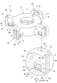
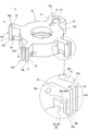
- It is a perspective view of a vane rotor. It is a front view of a vane rotor when it sees from a rear plate side.
- FIG. 4 is a cross-sectional view of the valve timing control device taken along the line AA of FIG. 3.
- FIG. 9A is a cross-sectional view of the vane rotor and the like taken along line BB of FIG. 9
- FIG. 9B is a cross-sectional view of the vane rotor and the like taken along line CC of FIG. It is a front view of the vane rotor of 3rd Embodiment when it sees from a rear plate side.
- FIG. 12 is a cross-sectional view of the vane rotor taken along the line DD of FIG. 11. It is a perspective view of the vane rotor of a 4th embodiment. It is a front view of the vane rotor of 4th Embodiment when it sees from a rear plate side.
- FIG. 15 is a cross-sectional view of the valve timing control device of the fourth embodiment taken along the line EE of FIG. 14. It is a perspective view of the 1st, 2nd leakage control member.
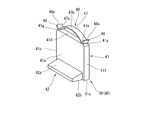
- (A) is a front view of the first and second leakage suppressing members
- (b) is a top view of the first and second leakage suppressing members
- (c) is a side view of the first and second leakage suppressing members. Is.
- (A) is a sectional view of the valve timing control device before hydraulic pressure is applied to the pressure receiving surface and the inclined surface
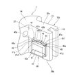
- (b) is a sectional view of the valve timing control device when hydraulic pressure is applied to the pressure receiving surface and the inclined surface. It is a figure. It is a front view of the 1st and 2nd leakage control member of a 5th embodiment. It is a perspective view of the vane rotor of a 5th embodiment of the state where the 1st and 2nd leak control member was attached.
- (A) is an explanatory view showing a state where the vane rotor is not rotating and centrifugal force is not acting on the second leakage suppression member
- (b) is a state where the vane rotor is rotating and the centrifugal force is the second leakage.
- valve timing control device for an internal combustion engine according to the present invention will be described in detail with reference to the drawings.
- the one applied to the valve operating device on the exhaust valve side is shown.
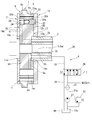
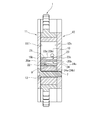
- FIG. 1 is an overall configuration diagram showing a part of a valve timing control device according to the present invention in cross section.
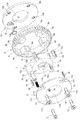
- FIG. 2 is an exploded perspective view of the valve timing control device.
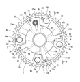
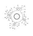
- 3 is a front view showing the vane rotor 7 and the like in the most advanced state with the front plate 11 removed, and
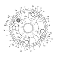
- FIG. 4 is a front view showing the vane rotor 7 and the like in the most retarded state with the front plate 11 removed.
- the valve timing control device includes a timing pulley 1, which is a driving rotary member that is rotationally driven by a crankshaft (not shown) via a timing belt, and a timing pulley 1.
- a camshaft 2 on the exhaust side which is relatively rotatably provided, and a phase change mechanism 3, which is arranged between the timing pulley 1 and the camshaft 2 and changes the relative rotational phase of the two 1, 2.
- the timing pulley 1 is formed integrally with a housing body 6a described later.
- a plurality of gear parts 1a around which a timing belt (not shown) is wound are integrally formed on the outer circumference of the timing pulley 1.
- the cam shaft 2 is rotatably supported on a cylinder head (not shown) via a plurality of cam bearings.
- a plurality of egg-shaped drive cams for opening and closing the exhaust valve are fixed at predetermined axial positions.
- a bolt insertion hole 2b into which a shaft portion 5a of a cam bolt 5 for fixing a vane rotor 7 which will be described later is inserted is formed in the inner shaft center direction of the tip end portion 2a side of the camshaft 2.
- a female screw 2c to which a male screw formed at the tip of the cam bolt 5 is screwed is formed at the tip of the bolt insertion hole 2b.
- the cam shaft 2 is restricted from moving in the rotation axis direction by a predetermined member.
- the phase changing mechanism 3 is fixed to a housing 6 having a working chamber inside and a tip 2a of the cam shaft 2 by a cam bolt 5, and is housed in the housing 6 so as to be relatively rotatable.
- the working chamber is partitioned by the vane rotor 7, which is a driven rotary body, the four first to fourth shoes 8a to 8d integrally formed on the inner peripheral surface of the housing body 6a of the housing 6 described later, and the vane rotor 7.
- the housing 6 includes a housing body 6a formed of a sintered metal in a cylindrical shape, a front plate 11 that closes a front end opening of the housing body 6a, and a rear plate 12 that closes a rear end opening. ..
- the housing body 6a and the front plate 11 and the rear plate 12 are fixed together by bolts 13 which are four fixing members that penetrate the bolt insertion holes 8e of the shoes 8a to 8d and the like.
- the front plate 11 is made of carbon steel and has a disk shape having a smaller wall thickness than the rear plate 12.
- a through hole 11a having a relatively large diameter into which the cam bolt 5 is inserted is formed through the center of the front plate 11.
- the front plate 11 is formed with four bolt insertion holes 11b through which the bolts 13 are inserted at circumferentially equidistant positions in the circumferential direction.
- Each bolt insertion hole 11b is a conical taper surface that is a counterbore part on which the conical taper part on the back side of the head of the bolt 13 is seated, with the diameter decreasing from the outer end surface 11c of the front plate 11 toward the vane rotor 7 side. It has 11d.
- the rear plate 12 is made of carbon steel in a disk shape, and a support hole 12a rotatably supported on the outer periphery of the camshaft 2 is formed at the center of the rear plate 12. Further, four female screw holes 12b into which a plurality of (four in the present embodiment) bolts 13 are screwed are formed at substantially circumferentially equidistant positions on the outer peripheral portion of the rear plate 12.
- the direction along the rotation axis of the vane rotor 7 is defined as “axial direction”, and the end portion on the front plate 11 side of the pair of axial end portions is “axial direction one end”. And the end portion on the rear plate 12 side is defined as “the other end in the axial direction”. Further, the direction orthogonal to the axial direction is defined as “radial direction”, and the direction around the rotation axis of the vane rotor 7 is defined as “circumferential direction”.
- the vane rotor 7 is integrally formed of, for example, sintered metal, and as shown in FIGS. 1 to 4, is a rotor fixed to the camshaft 2 by a cam bolt 5 inserted into a bolt insertion hole 7a formed at the center in the axial direction. And a plurality of (four in this embodiment) first to fourth vanes 15a to 15d radially formed on the outer peripheral surface of the rotor portion 14 at substantially 90° equidistant positions in the circumferential direction. Has been done.
- the rotor portion 14 is formed in a substantially cylindrical shape, and a circular fitting groove 14c into which the tip portion 2a of the camshaft 2 fits is formed on the other end surface 14b of the rotor portion 14, which is the end surface on the other axial end side.
- a circular fitting groove 14c into which the tip portion 2a of the camshaft 2 fits is formed on the other end surface 14b of the rotor portion 14, which is the end surface on the other axial end side.
- one end surface 14a of the rotor portion which is a flat end surface on the one end side in the axial direction of the rotor portion 14, is slidable on a facing inner end surface 11f of the front plate 11 through a minute side clearance 16. It comes to abut.
- the other end surface 14b of the rotor portion slidably contacts the facing inner end surface 12c of the rear plate 12 through a minute side clearance 17. In this way, the sealing function is exerted by the contact between the one end surface 14a of the rotor portion and
- first to fourth vanes 15a to 15d are arranged between the shoes 8a to 8d as shown in FIGS. 2 to 4. Further, in the first to fourth vanes 15a to 15d, seal members 19 for sealing while sliding on the inner peripheral surface of the housing body 6a are fitted in the seal grooves 18 formed in the respective arc-shaped outer peripheral surfaces. ing.
- one end surface 20a of the vane that is continuous with the one end surface 14a of the rotor portion (only the one end surface 20a of the first vane 15a is shown in FIG. 1) is, as shown in FIG.
- the inner end surface 11f of the front plate 11 is slidably abutted via a minute side clearance 16.
- the other end surface 20b of the vanes 15a to 15d that is continuous with the other end surface 14b of the rotor portion (only the other end surface 20b of the first vane 15a is shown in FIG. 1) is as shown in FIG.
- the rear plate 12 is slidably in contact with the inner end surface 12c of the rear plate 12 through a minute side clearance 17. Similar to the rotor portion one end surface 14a and the rotor portion other end surface 14b, the sealing function is exhibited by the contact between the vane one end surface 20a and the inner end surface 11f and the contact between the vane other end surface 20b and the inner end surface 12c. It has become.
- each of the vanes 15a to 15d has a maximum fan-shaped width along the circumferential direction of the first vane 15a, and the three vanes 15a to 15d other than the first vane 15a are surrounded by the circumferential direction.
- the width along the direction is set to be substantially the same as that of the first vane 15a.
- each of the vanes 15a to 15d has a first side surface 21 that faces the advance hydraulic chamber 10 in the circumferential direction and a second side surface that faces the retard hydraulic chamber 9 in the circumferential direction. 22 and.
- the first side surface 21 of each of the second to fourth vanes 15b to 15d has a rectangular first recess 21 with respect to the first side surface 21, as shown in the first side surface 21 of the third vane 15c of FIG.
- a recess 23 is formed.
- the first recess 23 communicates with the advance hydraulic chamber 10, and the working oil in the advance hydraulic chamber 10 is supplied to the first recess 23.
- each of the second to fourth vanes 15b to 15d is provided with a second recess 24 which is recessed in a rectangular shape with respect to the second side face 22 and has the same shape as the first recess 23 ( (See FIGS. 5 to 7).
- the second recess 24 communicates with the retard hydraulic chamber 9 so that the hydraulic oil in the retard hydraulic chamber 9 is supplied.
- the first and second recesses 23 and 24 will be described later in detail with reference to FIGS. 5 to 7.
- the vane rotor 7 relatively rotates toward the most retarded angle side, as shown in FIG. 4, the first side surface 21 of the first vane 15a abuts on the facing one side surface of the first shoe 8a facing in the circumferential direction and becomes maximum.
- the rotation position on the retard side is regulated.
- the second side surface 22 of the first vane 15a when relatively rotated toward the most advanced angle side, the second side surface 22 of the first vane 15a abuts on one opposing side surface of the second shoe 8b facing in the circumferential direction, and the second advanced side surface 22 moves toward the maximum advanced angle side.
- the rotation position is regulated.
- the first vane 15a and the first and second shoes 8a, 8b function as stoppers for restricting the most retarded position and the most advanced position of the vane rotor 7.
- the other second to fourth vanes 15b to 15d are in a separated state without abutting the facing side surfaces of the respective shoes 8a to 8d where the first and second side surfaces 21 and 22 are circumferentially opposed. Therefore, the contact accuracy between the first vane 15a and the first and second shoes 8a, 8b is improved, and the speed of supplying the hydraulic pressure to each retarded angle hydraulic chamber 9 and each advanced angle hydraulic chamber 10 is increased, thereby increasing the vane rotor. 7, the rotational response in the forward and reverse directions becomes high.
- Each retarded hydraulic chamber 9 and each advanced hydraulic chamber 10 communicate with the hydraulic circuit 4 via a first communication hole 9a and a second communication hole 10a formed inside the rotor portion 14 along the radial direction. ing.
- the hydraulic circuit 4 selectively supplies or discharges hydraulic oil (hydraulic pressure) to or from each retarded hydraulic chamber 9 and each advanced hydraulic chamber 10.
- hydraulic oil hydraulic pressure
- FIG. With respect to the retard oil passage 25 for supplying/discharging hydraulic pressure via the first communication hole 9a, and the advance oil passage 26 for supplying/discharging hydraulic pressure with respect to each advance hydraulic chamber 10 via the second communication hole 10a.
- the oil pump 27 is a general one such as a trochoid pump which is rotationally driven by the crankshaft of the engine.
- each of the retard oil passage 25 and the advance oil passage 26 is connected to the passage port of the electromagnetic switching valve 28, and the other end of each of the retard oil passage 25 and the advance oil passage 26 is a cylinder head, a cylinder block, or a camshaft 2 not shown.
- the retard angle hydraulic chambers 9 and the advance angle hydraulic chambers 10 communicate with each other through the first and second communication holes 9a and 10a.
- the electromagnetic switching valve 28 is a two-position three-port valve, and includes a spool valve element (not shown) slidably provided in the valve body in the axial direction by an electronic controller (not shown). Move it back and forth. As a result, the discharge passage 27a of the oil pump 27 is communicated with either of the oil passages 25, 26, and at the same time, the other oil passage 25, 26 is communicated with the drain passage 29.
- a filtration filter 31 is provided on the downstream side of the discharge passage 27a of the oil pump 27 and communicates with a main oil gallery M/G that supplies lubricating oil to the sliding parts of the internal combustion engine and the like on the downstream side. doing.
- the oil pump 27 is provided with a flow rate control valve 32 that discharges excess hydraulic oil discharged from the discharge passage 27a to the oil pan 30 and controls the flow rate to an appropriate flow rate.
- the electronic controller uses an internal computer to output information from various sensors such as a crank angle sensor (not shown), an air flow meter, an engine water temperature sensor, a throttle valve opening sensor, and a cam angle sensor that detects the current rotation phase of the camshaft 2.
- a signal is input to detect the current engine operating status.
- the electronic controller outputs a control pulse current to the coil of the electromagnetic switching valve 28 to control the moving position of each spool valve element, and thereby controls switching of each passage.
- a lock mechanism is provided between the first vane 15a and the rear plate 12 to restrain the vane rotor 7 in the most advanced position with respect to the housing 6.
- this locking mechanism is slidably accommodated in a sliding hole 33 formed through the first vane 15a in the inner axial direction and is capable of advancing and retracting with respect to the rear plate 12 side.
- the lock pin 34 provided in the rear plate 12, a lock hole 35 formed at a substantially central predetermined position in the radial direction of the rear plate 12, and the tip end portion 34a of the lock pin 34 is inserted to lock the vane rotor 7, and the start state of the engine. Accordingly, the tip end portion 34a of the lock pin 34 is inserted into or released from the lock hole 35, and the insertion/removal mechanism is formed.
- the whole of the lock pin 34 including the front end portion 34a is formed in a substantially cylindrical shape so that it can be easily inserted into the lock hole 35 from the axial direction, and is formed from the rear end side in the internal axial direction.
- a coil spring 36 is provided between the bottom surface of the groove and the inner end surface 11f of the front plate 11, and is a biasing member that biases the lock pin 34 in the advancing direction (inserting direction).
- the lock hole 35 is formed to be larger than the outer diameter of the tip end portion of the lock pin 34, is formed at a position biased toward the advance hydraulic chamber 10 side in the circumferential direction, and when the lock pin 34 is inserted, The relative conversion angle between the housing 6 and the vane rotor 7 is set to the position on the most advanced side.
- a semi-circular pressure receiving chamber 37 is formed at the side of the lock hole 35 at a position smaller than the outer diameter of the lock pin 34 and one step lower than the lock hole 35.
- the insertion/removal mechanism includes a coil spring 36 that urges the lock pin 34 in the advancing direction, and a hydraulic circuit for release (not shown) that supplies hydraulic pressure to the pressure receiving chamber 37 in the lock hole 35 to retract the lock pin 34. It is configured. In this releasing hydraulic circuit, the hydraulic pressures selectively supplied to the retarding hydraulic chamber 9 and the advancing hydraulic chamber 10 are supplied to the pressure receiving chamber 37 via a predetermined oil hole and act on the lock pin 34 in the backward direction. It is supposed to do.
- FIG. 5 is a perspective view of the vane rotor 7
- FIG. 6 is a front view of the vane rotor 7 when viewed from the rear plate 12 side
- FIG. 7 is a view of the valve timing control device taken along the line AA in FIG. FIG.
- the second to fourth vanes 15b to 15d have the first and second recesses 23 and 24 formed in the same shape.
- first and second recesses 23 and 24 of the second vane 15b will be described as a representative.
- a second recess 24 is formed in the second side surface 22 to be rectangular. Further, as shown in FIGS. 5 and 6, the second recess 24 is formed at a position near the connecting portion 38 between the rotor portion 14 and the second vane 15b. As shown in FIG. 5, the second recess 24 has a rectangular shape when viewed from the second side surface 22 side and has a long side along the axial direction.
- the second recess 24 communicates with the retard hydraulic chamber 9, and the working oil in the retard hydraulic chamber 9 is supplied into the second recess 24.
- the one end portion 24a which is the end portion on the one end side in the axial direction of the second concave portion 24, is formed by the pressure receiving surface 24b which is parallel to the vane one end surface 20a and the other end surface 20b of the vane and which is a substantially rectangular flat surface that receives hydraulic pressure.
- the other end 24c which is the end on the other end side in the axial direction, is opened to the other end face 20b of the vane and faces the inner end face 12c of the rear plate 12.
- the depth of the second recess 24 is smaller than half the width of the second vane 15b, which is the length between the first side surface 21 and the second side surface 22.
- first side surface 21 overlaps with the second recess 24 in the region from the other end surface 20 b of the vane to the position on the vane one end surface 20 a side with respect to the axial center portion of the second vane 15 b, that is, in the circumferential direction of the vane rotor 7.
- the first recessed portion 23 having the same shape as the second recessed portion 24 is formed in the region.
- the first recess 23 communicates with the advance hydraulic chamber 10, and the working oil in the advance hydraulic chamber 10 is supplied into the first recess 23.
- one end 23a which is the end on the one end side in the axial direction of the first recess 23, is parallel to the vane one end face 20a and the other end face 20b of the vane, and is a substantially rectangular flat surface that receives hydraulic pressure. Is closed by the pressure receiving surface 23b, and the other end portion 23c located on the other end side in the axial direction is open and faces the inner end surface 12c of the rear plate 12.
- the electronic controller maintains the non-energized state of the coil of the electromagnetic switching valve 28.
- the discharge passage 27a of the oil pump 27 and the retard oil passage 25 are communicated with each other, and at the same time, the advance oil passage 26 and the drain passage 29 are communicated with each other.
- each retard hydraulic chamber 9 flows into each retard hydraulic chamber 9 through the retard oil passage 25, and each retard hydraulic chamber 9 has a high pressure.
- the hydraulic oil in each advance hydraulic chamber 10 is discharged into the oil pan 30 through the advance oil passage 26 and the drain passage 29, so that the pressure in each advance hydraulic chamber 10 becomes low.
- each retarded hydraulic chamber 9 also flows from the hydraulic circuit for releasing into the pressure receiving chamber 37 and the lock hole 35 to become a high pressure, which causes the lock pin 34 to move backward and the tip portion 34a. Comes out of the lock hole 35, and free rotation of the vane rotor 7 is secured.
- the vane rotor 7 rotates toward the retarded angle side as shown in FIG. 4, and the first side surface 21 of the first vane 15a is opposed to the first shoe in the circumferential direction.
- the rotation position on the maximum retard side is regulated by abutting on one opposing side surface of 8a.
- the vane rotor 7, that is, the camshaft 2 has its relative rotation angle converted to the most retarded angle side with respect to the housing 6.
- the vane rotor 7 rotates toward the advance side with respect to the housing 6 so that the second side surface 22 of the first vane 15a faces one side surface of the second shoe 8b facing in the circumferential direction.
- the rotation position on the maximum advance side is regulated by the contact.
- the relative rotational position of the camshaft 2 with respect to the housing 6 is converted to the most advanced side.
- the opening/closing timing of the exhaust valve is controlled to the most advanced side, and the output of the engine in such a high rotation and high load range can be improved.
- FIG. 8A is a sectional view of the valve timing control device before the hydraulic pressure is applied to the pressure receiving surfaces 23b and 24b
- FIG. 8B is a valve timing control device when the hydraulic pressure is applied to the pressure receiving surfaces 23b and 24b.
- the internal pressure of the retard hydraulic chamber 9 and the internal pressure of the advance hydraulic chamber 10 are the side clearance 16 between the vane one end face 20 a of the second vane 15 b and the inner end face 11 f of the front plate 11. It is higher than the internal pressure.
- the second vane 15b is swung toward the most advanced angle side as indicated by an arrow G in FIG. 8A, and the volume of the advanced angle hydraulic chamber 10 is widened.
- the volume of the retarding hydraulic chamber 9 becomes narrower. That is, due to the positive alternating torque of the camshaft 2, the internal pressure of the advance hydraulic chamber 10 decreases, while the internal pressure of the retard hydraulic chamber 9 increases. Therefore, a differential pressure is generated between the retard hydraulic chamber 9 and the advance hydraulic chamber 10, and the retard hydraulic chamber 9 advances through the side clearance 16 as shown by an arrow H in FIG. A continuous flow of hydraulic oil is generated in the angular hydraulic chamber 10.
- the hydraulic oils from the advance hydraulic chamber 10 and the retard hydraulic chamber 9 are supplied to the first and second recesses 23 and 24 of the second vane 15b, respectively.
- the hydraulic oil in the first and second recesses 23 and 24 causes the pressure receiving surfaces 23b and 24b of the first and second recesses 23 and 24 to move toward the rear plate 12 side, as indicated by an arrow I in FIG. 8B.
- the hydraulic pressure acts in the axial direction from the side toward the front plate 11 side. Due to this hydraulic pressure I, the vane rotor 7 moves toward the front plate 11 side along the axial direction, and the one end surface 20a of the second vane 15b is pressed against the inner end surface 11f of the front plate 11.
- the hydraulic pressure is applied to the inner end surface 12c of the rear plate 12 as indicated by a dashed arrow Q in FIG. To work. As a result, the rear plate 12 moves in the direction away from the second vane 15b together with the front plate 11 connected via the housing body 6a (see FIG. 1 and the like). Therefore, the inner end surface 11f of the front plate 11 is pressed against the vane one end surface 20a of the second vane 15b.
- first recess 23 and the second recess 24 overlap each other in the circumferential direction of the vane rotor 7. That is, the first recess 23 and the second recess 24 are formed so as to overlap each other in the circumferential direction of the vane rotor 7 on the first and second side surfaces 21 and 22 which are continuous over a relatively wide range.
- first and second recesses 23 and 24 are formed so as not to overlap each other in the circumferential direction of the vane rotor 7, the advance hydraulic chamber 10 and the retard hydraulic chamber of the first and second recesses 23 and 24 are formed.
- the opening area to 9 becomes narrow. As a result, it becomes difficult for hydraulic oil to flow into the first and second recesses 23 and 24, and the hydraulic pressure may be delayed from acting on the pressure receiving surfaces 23b and 24b, that is, the responsiveness of the hydraulic pressure may deteriorate.
- the first and second recesses 23 and 24 are circumferentially overlapped with each other to open the first and second recesses 23 and 24 to the advance hydraulic chamber 10 and the retard hydraulic chamber 9.
- the flow of hydraulic oil is promoted into the first and second recesses 23, 24, and the response of hydraulic pressure is improved.
- the vane one end surface 20a of the second vane 15b easily contacts the inner end surface 11f of the front plate 11, and the performance of the internal combustion engine can be improved.
- FIG. 9 shows the second embodiment of the present invention and is a front view of the vane rotor 7 as viewed from the rear plate 12 side.
- 10A is a cross-sectional view of the vane rotor 7 and the like taken along line BB of FIG. 9, and
- FIG. 10B is a cross-sectional view of the vane rotor 7 and the like taken along line CC of FIG. is there.
- 10(a) and 10(b) are shown as a cross-sectional view of the vane rotor 7 and the like housed in the housing 6.
- first recess 23 and the second recess 24 are provided so as to be staggered in the radial direction of the vane rotor 7. That is, the first recess 23 and the second recess 24 are provided so as not to overlap in the circumferential direction of the vane rotor 7.
- the first recess 23 is located near the seal groove 18 in the radial direction, and is formed so as to be recessed in a rectangular shape with respect to the first side surface 21.
- the width of the first recess 23 of the present embodiment along the radial direction is smaller than the width of the first recess 23 of the first embodiment along the radial direction.
- the depth of the first concave portion 23 of the present embodiment is larger than half the width of the second vane 15b, which is the length between the first side surface 21 and the second side surface 22, and is the same as that of the first embodiment. It is deeper than the depth of the first recess 23. Accordingly, the pressure receiving area of the pressure receiving surface 23b of the first recess 23 of the present embodiment is larger than the pressure receiving area of the pressure receiving surface 23b of the first recess 23 of the first embodiment.
- the second recess 24 has a shape similar to that of the first recess 23, and is formed in the second side surface 22 at a position closer to the connecting portion 38 so as to be recessed in a rectangular shape with respect to the second side surface 22. There is. Similar to the first recess 23, the width of the second recess 24 of the present embodiment along the radial direction is smaller than the width of the second recess 24 of the first embodiment along the radial direction.
- the depth of the second recess 24 of the present embodiment is deeper than the depth of the second recess 24 of the first embodiment, and the pressure receiving area of the pressure receiving surface 24b of the second recess 24 of the present embodiment is It is larger than the pressure receiving area of the pressure receiving surface 24b of the second recess 24 of the first embodiment.
- FIG. 11 shows a third embodiment of the present invention, and is a front view of the vane rotor 7 when viewed from the rear plate 12 side, and FIG. 12 is a sectional view of the vane rotor 7 taken along line DD in FIG. ..
- the first and second recesses 23 and 24 are not formed in the second to fourth vanes 15b to 15d but in the rotor end face 14b which is the end face on the other end side in the axial direction of the rotor unit 14. Has been done.
- the first recess 23 is formed at a position adjacent to the connecting portion 38 of the second vane 15b in the circumferential direction of the vane rotor 7 so as to be recessed in a rectangular shape with respect to the other end surface 14b of the rotor portion. As shown in FIG. 11, the shape of the first recess 23 when viewed in the axial direction is substantially square.
- the first recessed portion 23 opens on the other end surface 14b of the rotor portion and also opens on the outer peripheral surface 14d of the rotor portion 14.
- the second recess 24 has a shape similar to that of the first recess 23, and is located at a position opposite to the first recess 23 across the connecting portion 38 in the circumferential direction of the vane rotor 7 and at the other end surface 14b of the rotor portion. On the other hand, it is formed to be recessed in a rectangular shape. Similar to the first recess 23, the second recess 24 has a substantially square shape when viewed from the axial direction, and is open to the other end surface 14b of the rotor portion and the outer peripheral surface 14d.
- the first concave portion 23 and the second concave portion 24 are formed on the other end surface 14b of the rotor portion, which is the axial end surface of the rotor portion 14.
- first and second recesses 23 and 24 By thus forming the first and second recesses 23 and 24 on the other end surface 14b of the rotor portion, it is not necessary to form the first and second recesses 23 and 24 on the second to fourth vanes 15b to 15d. Therefore, a wide sealing surface is secured between the other end surface 20b of the second to fourth vanes 15b to 15d and the inner end surface 12c of the rear plate 12 (see FIGS. 8A and 8B, etc.). be able to. Therefore, the amount of hydraulic oil leaking through the side clearance between the other end surface 20b of the vane and the inner end surface 12c is reduced, and the vane rotor 7 can be operated efficiently.
- FIG. 13 is a perspective view of the vane rotor 7 used in the fourth embodiment
- FIG. 14 is a front view of the vane rotor 7 when viewed from the rear plate 12 side
- FIG. 15 is a section taken along line EE in FIG. It is a sectional view of a valve timing control device.
- First and second leakage suppressing members 39 and 40 which are first and second members for suppressing the leakage of the hydraulic oil from the side clearance 43 (see FIG. 18A), are provided, respectively.
- the first and second leakage suppression members 39, 40 are made of metal and have the same shape.
- a plate-shaped plate-shaped portion 41 extending along the axial direction and a substantially plate-shaped plate 41 radially formed so as to be orthogonal to the plate-shaped portion 41 are formed. And a flange portion 42, respectively.
- the first and second leakage suppression members 39 and 40 are plate-like portions 41 that are provided slidably in the axial directions with the bottom surfaces 23d and 24d of the first and second recesses 23 and 24, and the plate-like portions.
- Each of the flange portions 42 is formed so as to project in the radial direction from 41 and is capable of contacting the inner end surface 12c of the rear plate 12.
- the first and second leakage suppression members 39 and 40 slide toward the rear plate 12 by the hydraulic pressure supplied to the first and second recesses 23 and 24 acting on the flange portion 42, whereby the flange portion. 42 is configured to come into contact with the inner end surface 12c of the rear plate 12 and exert a sealing function against hydraulic oil.
- FIG. 16 is a perspective view of the first and second leakage suppression members 39 and 40
- FIG. 17A is a front view of the first and second leakage suppression members 39 and 40
- FIG. 17C is a side view of the first and second leakage suppressing members 39, 40, which is a top view of the leakage suppressing members 39, 40.
- first and second leakage suppressing members 39 and 40 have the same shape, the first leakage suppressing member 39 will be described below as a representative. 16 and 17(a) to 17(c), the reference numerals of the second leakage suppression member 40 are shown in parentheses.
- the plate-like portion 41 has a substantially rectangular shape as shown in FIG. 17A, and is a first surface 41a on which the flange portion 42 is formed to project, and a surface located on the back side of the first surface 41a, A second surface 41b slidable with the bottom surface 23d of the first recess 23, a third surface 41c orthogonal to the first and second surfaces 41a, 41b and capable of contacting the inner end surface 12c of the rear plate 12, and It has a fourth surface 41d that is parallel to the third surface 41c, and fifth and sixth surfaces 41e and 41f that are orthogonal to the third and fourth surfaces 41c and 41d.
- the fourth surface 41d is connected to the fifth and sixth surfaces 41e, 41f via a pair of chamfered portions 41g, 41g inclined toward the third surface 41c side with respect to the fourth surface 41d.
- the pair of side portions 41h, 41h of the plate-like portion 41 including the fifth and sixth surfaces 41e, 41f are formed in a pair of side surfaces 23e, 23e of the first recess 23 adjacent to the bottom surface 23d.
- the groove portions 23f and 23f are fitted into the groove portions 23f and 23f, respectively (see FIG. 14).
- the side portions 41h and 41h are arranged in the groove portions 23f and 23f with a predetermined gap therebetween so that the side portions 41h and 41h can move along the axial direction when the hydraulic pressure supplied to the first recess portion 23 acts on the flange portion 42. To be done.
- the flange portion 42 has a length shorter than the length of the plate-shaped portion 41 along the radial direction (the length in the left-right direction of FIG. 17A), and the first surface 41 a of the plate-shaped portion 41. Of these, it stands up from a position adjacent to the third surface 41c so as to be orthogonal to the plate-shaped portion 41.
- the flange portion 42 has an inclined pressure receiving surface 42a that receives the hydraulic pressure supplied to the first recess 23, and the hydraulic pressure acts on the pressure receiving surface 42a so that the rear leakage control member 39 moves to the rear plate 12 side. It has a contact surface 42b that contacts the inner end surface 12c of the plate 12. As shown in FIG.
- the pressure receiving surface 42a is inclined so that the thickness of the flange portion 42 (thickness in the vertical direction of FIG. 17C) gradually decreases as the distance from the first surface 41a increases.
- the contact surface 42b is a flat surface that is continuous with the third surface 41c of the plate-shaped portion 41, and when the contact surface 42b contacts the inner end surface 12c of the rear plate 12, the inner surface together with the third surface 41c. It comes into contact with 12c.
- FIG. 18(a) is a sectional view of the valve timing control device before the hydraulic pressure is applied to the pressure receiving surfaces 23b, 24b, 42a, 42a
- FIG. 18(b) is the hydraulic pressure applied to the pressure receiving surfaces 23b, 24b, 42a, 42a.
- FIG. 3 is a cross-sectional view of the valve timing control device during operation.
- the internal pressure of the retard hydraulic chamber 9 and the internal pressure of the advance hydraulic chamber 10 are the internal pressure of the side clearance 16 between the one end face 20a and the inner end face 11f of the vane, and the other end face 20b of the vane. It is higher than the internal pressure of the side clearance 43 with the inner end surface 12c.
- FIG. 18A the engagement between the lock pin 34 and the lock hole 35 as shown in FIG. 1 is released, and the vane rotor 7 is selectively supplied to the retard hydraulic chamber 9 and the advance hydraulic chamber 10. It is configured to move in the circumferential direction (vertical direction in FIG. 18A) by the hydraulic pressure.
- the second vane 15b is swung toward the most advanced angle side as indicated by an arrow G in FIG. 18A, and the volume of the advanced angle hydraulic chamber 10 is widened.
- the volume of the retarding hydraulic chamber 9 becomes narrower. That is, due to the positive alternating torque of the camshaft 2, the internal pressure of the advance hydraulic chamber 10 decreases, while the internal pressure of the retard hydraulic chamber 9 increases.
- hydraulic pressures are respectively supplied from the advance hydraulic chamber 10 and the retard hydraulic chamber 9 to the first and second recesses 23 and 24 of the second vane 15b. Therefore, in addition to the hydraulic pressure I acting along the axial direction acting on the pressure receiving surfaces 23b, 24b of the first and second recesses 23, 24, the pressure receiving surfaces 42a, 42a of the first and second leakage suppressing members 39, 40 are also included. In addition, the hydraulic pressure acts from the front plate 11 side to the rear plate 12 side along the axial direction, as indicated by an arrow K in FIG.
- the first and second leakage suppression members 39, 40 move toward the rear plate 12 side along the axial direction, and the contact surface 42b of the flange portion 42 and the third surface 41c of the plate-shaped portion 41 rear. It is pressed against the inner end surface 12c of the plate 12. As a result, friction occurs between the contact surface 42b and the third surface 41c and the inner end surface 12c, and the second vane 15b is held by the rear plate 12. Therefore, the valve timing is maintained at the specified position for achieving the desired operation of the internal combustion engine, the amount of exhaust gas is reduced, and the performance of the internal combustion engine can be improved.
- the side clearance 43 is sealed by the contact between the contact surface 42b and the third surface 41c and the inner end surface 12c. This can prevent the hydraulic oil from leaking from the retard hydraulic chamber 9 through the side clearance 43 to the advance hydraulic chamber 10 (arrow J).
- FIG. 19 and 20 show a fifth embodiment of the present invention
- FIG. 19 is a front view of the first and second leakage suppressing members 39, 40
- FIG. 20 is the first and second leakage suppressing members 39, 40 mounted. It is a perspective view of the vane rotor 7 of 5th Embodiment of the state.
- the reference numerals of the second leakage suppressing member 40 having the same shape as the first leakage suppressing member 39 are shown in parentheses.
- FIG. 20 the shape of the second recess 24 inside the second vane 15b is shown by a broken line.
- the chamfered portions 41g and 41g of the fourth embodiment are eliminated, and the fifth and sixth surfaces 41e and 41f of the first and second leakage suppression members 39 and 40 face the flange portion 42 side. Accordingly, it is formed as an inclined surface so that the width between the fifth and sixth surfaces 41e and 41f (width in the left-right direction in FIG. 19) gradually increases.
- the fifth and sixth surfaces 41e, 41f are formed symmetrically with respect to the flange portion 42.
- the second recess 24 is opened in the second side surface 22 and the other end surface 20b of the vane, and is connected to the flange portion housing portion 44 that houses the flange portion 42, and the flange portion housing portion 44. It has a plate-shaped portion accommodating portion 45 that accommodates 41.
- the flange accommodating portion 44 has a substantially square shape when viewed from the second side surface 22 side, and the length along the axial direction of the vane rotor 7 is the second concave portion 24 of the first and fourth embodiments. It is shorter than the length along the axial direction.
- one end portion 44a located on one end side in the axial direction is closed by a pressure receiving surface 44b that is a flat surface that is parallel to the vane one end surface 20a and the other end surface 20b of the vane, and that receives a hydraulic pressure.
- the other end portion 44c located on the other end side in the axial direction opens to the other end surface 20b of the vane.
- the distance between the one end portion 44a and the other end portion 44c is longer than the height of the flange portion 42 along the axial direction (the height in the up-down direction in FIG. 19). It is movable in the axial direction between the one end 44a and the other end 44c.
- the flange accommodating portion 44 is provided with a pair of surfaces 44d and 44e that are continuous in the axial direction from both ends of the pressure receiving surface 44b to the other end surface 20b of the vane.
- the distance between the surfaces 44d and 44e is larger than the width of the flange portion 42 along the radial direction (the width in the left-right direction in FIG. 19), which allows the flange portion 42 to move between the surfaces 44d and 44e. It is movable in the radial direction.
- the plate-shaped portion accommodating portion 45 is formed on the inner side of the second vane 15 b with respect to the flange portion accommodating portion 44, and has a generally rectangular shape whose shape when viewed from the second side surface 22 side is larger than that of the flange portion accommodating portion 44. It has a shape.
- one end portion 45a located on one axial side is closed by a surface 45b which is a surface parallel to the vane one end surface 20a and the other end surface 20b of the vane, and is located on the other axial side.
- the other end portion 45c is opened to the other end surface 20b of the vane.
- the distance between the one end portion 45a and the other end portion 45c is longer than the height of the plate-shaped portion 41 along the axial direction (the height in the up-down direction in FIG. 19).
- 41 is axially movable between one end 45a and the other end 45c.
- a surface 45d that is continuous along the axial direction from the end of the surface 45b on the rotor portion 14 side to the other end surface 20b of the vane, and a vane from the end of the surface 45b on the seal groove 18 side.
- An inclined surface 45e that inclines at the same inclination angle as the sixth surface 41f of the plate-like portion 41 is provided up to the other end surface 20b.
- the maximum distance between the surface 45d and the inclined surface 45e is longer than the maximum distance between the inclined fifth and sixth surfaces 41e and 41f (see FIGS. 21(a) and 21(b)).
- the plate-like portion 41 is movable in the radial direction between the fifth and sixth surfaces 41e and 41f.
- FIG. 21A is an explanatory view showing a state where the vane rotor 7 is not rotating and a centrifugal force is not acting on the second leakage suppression member 40
- FIG. 21B is a state when the vane rotor 7 is rotating
- FIG. 6 is an explanatory diagram showing a state in which a force acts on a second leakage suppression member 40. 21A and 21B, only the surfaces 45b and 45d and the inclined surface 45e of the plate portion accommodating portion 45 are shown.
- the plate-like portion 41 is located at the center of the plate-like portion accommodating portion 45, and the inclined sixth surface 41f extends radially from the inclined surface 45e. It is located at a distance from.
- FIG. 22 is a perspective view of the vane rotor 7 used in the sixth embodiment
- FIG. 23 is a perspective view of the first and second leakage suppressing members 39 and 40 and the leaf spring 46 of the sixth embodiment
- FIG. 24 is a second leakage. It is a partial perspective view of the vane rotor 7 of 6th Embodiment in the state which assembled the suppression member 40 and the leaf spring 46. 22 and 24, the shape of the second recess 24 inside the second vane 15b is shown by a broken line.
- the inclined surface 45e of the plate-shaped portion housing portion 45 of the fifth embodiment is eliminated, and the plate-shaped portion housing portion 45 has a surface 45f orthogonal to the surface 45b.
- the distance between the surface 45d and the surface 45f of the plate-shaped portion accommodating portion 45 is larger than the width of the first and second leakage suppressing members 39 and 40 along the radial direction (width in the left-right direction in FIG. 23). It is slightly shorter.
- the distance between the one end portion 45a and the other end portion 45c of the plate-shaped portion accommodating portion 45 is larger than the height of the first and second leakage suppressing members 39, 40 along the axial direction.
- a leaf spring 46 which is a biasing member that biases the second leakage suppression member 40, is provided in a compressed state against the inner end surface of the rear cover (not shown).
- the leaf spring 46 is bent so as to be separated from the fourth surface 41d from an arc-shaped portion 47 that is curved in an arc shape so as to be separated from the fourth surface 41d, and both end portions 47a and 47a of the arc-shaped portion 47. It has a pair of bent portions 48, 48.
- both end portions 47a, 47a are elastic at the portions of the fourth surface 41d near the chamfered portions 41g, 41g. Abutting each other, the elastic deformation is possible in the axial direction.
- bent portions 48, 48 regulate the radial movement of the second leakage suppression member 40 by the tip portions 48a, 48a elastically contacting the surfaces 45d, 45f of the plate-shaped portion housing portion 45, respectively. ..
- the pressure receiving surfaces 23b, 24b are disclosed as examples in which the vane one end surface 20a and the other end surface 20b of the vane are configured to be parallel, but the pressure receiving surfaces for the one end surface 20a and the other end surface 20b of the vane are disclosed.
- a configuration in which the is inclined can also be applied to the present invention.
- first and second leakage suppressing members 39 and 40 are provided in the first and second recesses 23 and 24, respectively.
- the first and second leakage suppressing members 39 and 40 may be provided without forming them.
- a guide groove that is continuous in the axial direction is formed on the first and second side surfaces 21 and 22, and further, the guide groove is formed on the second surface 41b of the first and second leakage suppressing members 39 and 40. Forming a protrusion that is guided along.
- the example in which the leaf spring 46 is used as the biasing member is disclosed, but another biasing member, for example, a coil spring may be used.
- valve timing control device used for the exhaust side camshaft is shown, but it may be used for the intake side camshaft.
- valve timing control device for an internal combustion engine based on the embodiment described above, for example, the following modes are conceivable.
- a valve timing control device for an internal combustion engine includes a housing to which a rotational force from a crankshaft is transmitted, and a vane rotor that is arranged in the housing and fixed to a camshaft.
- a vane rotor having a vane for partitioning the working chamber into a first hydraulic chamber and a second hydraulic chamber, the vane rotor being rotatable relative to the housing when hydraulic pressure acts on the first hydraulic chamber or the second hydraulic chamber;
- a first recess provided in the vane rotor and communicating with the first hydraulic chamber, having a pair of end portions in a direction of a rotation axis of the vane rotor, and one end portion of the pair of end portions is closed.
- a first recess having an opening at the other end, and a second recess provided in the vane rotor and communicating with the second hydraulic chamber, the first recess having a pair of ends in the direction of the rotation axis of the vane rotor; A second recess whose one end is closed and the other end is open.
- the vane has a first side surface facing the first hydraulic chamber and a second side surface facing the second hydraulic chamber, and the first recess is It is provided so as to be recessed in the first side surface, and the second recess is provided so as to be recessed in the second side surface.
- one end of the first recess and one end of the second recess have a pressure receiving surface on which hydraulic pressure acts.
- the first concave portion and the second concave portion overlap each other in a circumferential direction that is a direction around the rotation axis of the vane rotor.
- the first recesses and the second recesses are provided alternately in a radial direction that is a direction orthogonal to a rotation axis of the vane rotor.
- the vane rotor has a cylindrical rotor portion that is integrally formed with the vane and is fixed to the camshaft, The concave portion and the second concave portion are formed on the axial end surface of the rotor portion.
- the first concave portion and the second concave portion are provided in a vicinity of a connecting portion between the vane and the rotor portion on an axial end surface of the rotor portion. Has been formed.
- valve timing control device for an internal combustion engine based on the above-described embodiment, for example, the following modes are conceivable.
- a valve timing control device for an internal combustion engine includes a housing to which a rotational force from a crankshaft is transmitted, and a vane rotor that is arranged in the housing and fixed to a camshaft.
- a vane rotor having a vane for partitioning the working chamber into a first hydraulic chamber and a second hydraulic chamber, the vane rotor being rotatable relative to the housing when hydraulic pressure acts on the first hydraulic chamber or the second hydraulic chamber;
- the first member and the second member are held by the vane so as to be movable along the direction of the rotation axis of the vane rotor.
- the vane communicates with the first hydraulic chamber, has a pair of end portions in a direction of a rotation axis of the vane rotor, and One end of the end portion is closed, the other end portion is open, and a first recess, which communicates with the second hydraulic chamber, and has a pair of end portions in the direction of the rotation axis of the vane rotor.
- the first member is held in the first recessed portion, and a plate-shaped portion extending in a direction of a rotation axis of the vane rotor, and the plate-shaped portion. From the flange portion extending so as to be orthogonal to the direction of the rotation axis, the plate-shaped portion, on the end surface radially outward with respect to the rotation axis, is orthogonal to the rotation axis toward the flange portion side.
- the first recess has an abutment surface capable of abutting the inclined surface, the inclined surface having a gradually increasing width along the radial direction.
- the first recess is provided with a first biasing member that presses the first member against the housing, and the second recess is provided.
- a first biasing member that presses the second member is provided on the housing.
Landscapes
- Engineering & Computer Science (AREA)
- Mechanical Engineering (AREA)
- General Engineering & Computer Science (AREA)
- Valve Device For Special Equipments (AREA)
Abstract
ベーンロータ(7)は、ハウジング内の作動室を遅角油圧室(9)と進角油圧室(10)とに区切る第2ベーン(15b)を有している。第2ベーン(15b)は、進角油圧室(10)と周方向に対向する第1側面(21)と、遅角油圧室(9)と周方向に対向する第2側面(22)とを有している。第1側面(21)および第2側面(22)には、ベーン他端面(20b)から第2ベーン(15b)の軸方向中央部よりもベーン一端面(20a)側の位置までの領域に、第1凹部(23)および第2凹部(24)がそれぞれ形成されている。第1凹部(23)および第2凹部(24)は、軸方向一端側が閉塞し、軸方向他端側が開口している。
Description
本発明は、内燃機関のバルブタイミング制御装置に関する。
内燃機関のバルブタイミング制御装置として、例えば以下の特許文献1に記載されたバルブタイミング制御装置が知られている。
特許文献1に記載の従来のバルブタイミング制御装置は、クランクシャフトからの回転力が伝達されるハウジングと、該ハウジング内に配置されると共にカムシャフトに固定されるベーンロータとを備えている。ハウジングは、ベーンロータを収容する円筒状のハウジング本体と、該ハウジング本体の軸方向の両開口端面を閉塞するフロントプレートおよびリアプレートと、を備えている。ベーンロータは、ハウジング内の作動室を第1油圧室と第2油圧室とに区切るベーンを有し、第1油圧室または第2油圧室に油圧が選択的に給排されることによりハウジングに対して相対回転可能となっている。
特許文献1に記載の従来のバルブタイミング制御装置は、ベーンロータが相対回転可能な作動時において、カムシャフトに交番トルクが生じると、この交番トルクに起因して、ベーンロータのベーンが周方向に振られてしまう。これにより、バルブタイミングが、内燃機関の望ましいタイミングからずれてしまい、内燃機関の性能が低下する虞があった。
本発明は、従来の実情に鑑みて案出されたもので、内燃機関の性能を向上させることができる内燃機関のバルブタイミング制御装置を提供することを一つの目的としている。
本発明の好ましい態様によれば、ベーンロータに、第1油圧室と連通する第1凹部と、第2油圧室と連通する第2凹部とが設けられている。第1凹部および第2凹部の各々は、ベーンロータの回転軸線の方向において一対の端部を有し、該一対の端部のうち一端部が閉塞し、前記一対の端部のうち他端部が開口している。
本発明によれば、機関の運転に応じた所望のバルブタイミングの保持性を確保して、内燃機関の性能を向上させることができる。
以下、本発明に係る内燃機関のバルブタイミング制御装置の実施形態を図面に基づいて詳述する。本実施形態では、排気弁側の動弁装置に適用したものを示している。
[第1実施形態]
図1は本発明に係るバルブタイミング制御装置の一部を断面で示す全体構成図である。図2はバルブタイミング制御装置の分解斜視図である。図3はフロントプレート11を外して最進角状態のベーンロータ7等を示した正面図、図4はフロントプレート11を外して最遅角状態のベーンロータ7等を示した正面図である。
図1は本発明に係るバルブタイミング制御装置の一部を断面で示す全体構成図である。図2はバルブタイミング制御装置の分解斜視図である。図3はフロントプレート11を外して最進角状態のベーンロータ7等を示した正面図、図4はフロントプレート11を外して最遅角状態のベーンロータ7等を示した正面図である。
バルブタイミング制御装置(VTC)は、図1および図2に示すように、図外のクランクシャフトによりタイミングベルトを介して回転駆動される駆動回転体であるタイミングプーリ1と、該タイミングプーリ1に対して相対回転可能に設けられた排気側のカムシャフト2と、タイミングプーリ1とカムシャフト2との間に配置されて、該両者1,2の相対回転位相を変更する位相変更機構3と、該位相変更機構3を作動させる油圧回路4と、を備えている。
タイミングプーリ1は、後述するハウジング本体6aと一体に形成されている。タイミングプーリ1の外周には、図外のタイミングベルトが巻回される複数の歯車部1aが一体に形成されている。
カムシャフト2は、図示せぬシリンダヘッド上に複数のカム軸受を介して回転可能に支持されている。カムシャフト2の外周面には、排気弁を開閉作動させる卵形の複数の駆動カムが軸方向の所定位置に固定されている。カムシャフト2の先端部2a側の内部軸心方向には、後述するベーンロータ7を軸方向から固定するカムボルト5の軸部5aが挿入されるボルト挿入孔2bが形成されている。なお、このボルト挿入孔2bの先端部には、カムボルト5の先端に形成された雄ねじがねじ留めされる雌ねじ2cが形成されている。なお、カムシャフト2は、所定の部材によって回転軸方向の移動が規制されている。
位相変更機構3は、図1~図4に示すように、内部に作動室を有するハウジング6と、カムシャフト2の先端部2aにカムボルト5によって固定されて、ハウジング6内に相対回転可能に収容された従動回転体であるベーンロータ7と、ハウジング6の後述するハウジング本体6aの内周面に一体に形成された4つの第1~第4シュー8a~8dとベーンロータ7によって作動室が仕切られたそれぞれ4つの遅角作動室である遅角油圧室(第2油圧室)9および進角作動室である進角油圧室(第1油圧室)10と、を備えている。
ハウジング6は、焼結金属によって円筒状に形成されたハウジング本体6aと、該ハウジング本体6aの前端開口を閉塞するフロントプレート11と、後端開口を閉塞するリアプレート12と、から構成されている。ハウジング本体6aとフロントプレート11およびリアプレート12とは、各シュー8a~8dの各ボルト挿入孔8e等を貫通する4本の固定部材であるボルト13によって共締め固定されている。
フロントプレート11は、炭素鋼によって、リアプレート12よりも小さい肉厚を有する円盤状に形成されている。フロントプレート11の中央には、カムボルト5が挿入される比較的大径な貫通孔11aが貫通形成されている。フロントプレート11は、外周部の周方向等間隔位置にボルト13が挿入される4つのボルト挿入孔11bが貫通形成されている。各ボルト挿入孔11bは、フロントプレート11の外端面11cからベーンロータ7側に向かって円錐テーパ状に縮径し、ボルト13の頭部の裏側の円錐テーパ部が着座するザグリ部である円錐テーパ面11dを有している。
リアプレート12は、炭素鋼により円盤状に形成されており、中央にカムシャフト2の外周に回転可能に支持される支持孔12aが貫通形成されている。また、リアプレート12の外周部の周方向のほぼ等間隔位置には、複数(本実施形態では4本)のボルト13が螺着する4つの雌ねじ孔12bがそれぞれ形成されている。
ここで、以下の説明の便宜上、ベーンロータ7の回転軸線に沿った方向を「軸方向」と定義し、該軸方向の一対の端部のうちフロントプレート11側の端部を「軸方向一端」と定義し、リアプレート12側の端部を「軸方向他端」と定義する。また、軸方向と直交する方向を「径方向」と定義し、ベーンロータ7の回転軸線周りの方向を「周方向」と定義する。
ベーンロータ7は、例えば焼結金属によって一体に形成され、図1~図4に示すように、軸方向中央に形成されたボルト挿入孔7aに挿入されるカムボルト5によってカムシャフト2に固定されたロータ部14と、該ロータ部14の外周面に周方向のほぼ90°等間隔位置に放射状に突出形成された複数(本実施形態では4枚)の第1~第4ベーン15a~15dとから構成されている。
ロータ部14は、ほぼ円筒状に形成され、ロータ部14の軸方向他端側の端面であるロータ部他端面14bにカムシャフト2の先端部2aが嵌合する円形状の嵌合溝14cが形成されている。ロータ部14の軸方向一端側の平坦な端面であるロータ部一端面14aは、図1に示すように、フロントプレート11の対向する内端面11fに微小なサイドクリアランス16を介して摺動可能に当接するようになっている。一方、ロータ部他端面14bは、図1に示すように、リアプレート12の対向する内端面12cに微小なサイドクリアランス17を介して摺動可能に当接するようになっている。このように、ロータ部一端面14aと内端面11fとの当接、並びにロータ部他端面14bと内端面12cとの当接により、シール機能が発揮されるようになっている。
一方、第1~第4ベーン15a~15dは、図2~図4に示すように、それぞれが各シュー8a~8dの間に配置されている。また、第1~第4ベーン15a~15dは、それぞれの円弧状外周面に形成されたシール溝18内に、ハウジング本体6aの内周面に摺動しつつシールするシール部材19がそれぞれ嵌め込まれている。各ベーン15a~15dのうちロータ部一端面14aと連続するベーン一端面20a(図1には、第1ベーン15aのベーン一端面20aのみが示されている)は、図1に示すように、フロントプレート11の内端面11fに対して微小なサイドクリアランス16を介して摺動可能に当接している。一方、各ベーン15a~15dのうちロータ部他端面14bと連続するベーン他端面20b(図1には、第1ベーン15aのベーン他端面20bのみが示されている)は、図1に示すように、リアプレート12の内端面12cに対して微小なサイドクリアランス17を介して摺動可能に当接している。ロータ部一端面14aおよびロータ部他端面14bと同様に、ベーン一端面20aと内端面11fとの当接、並びにベーン他端面20bと内端面12cとの当接により、シール機能が発揮されるようになっている。
また、各ベーン15a~15dは、第1ベーン15aの周方向に沿った幅が扇状の最大幅に設定されて、第1ベーン15a以外の3枚の第2~第4ベーン15b~15dの周方向に沿った幅が第1ベーン15aよりも小さいほぼ同一の幅になるように設定されている。
各ベーン15a~15dは、図3および図4に示すように、各進角油圧室10と周方向に対向する第1側面21と、各遅角油圧室9と周方向に対向する第2側面22と、を備えている。第2~第4ベーン15b~15dの第1側面21には、図2の第3ベーン15cの第1側面21に示されているように、第1側面21に対して矩形に凹んだ第1凹部23が形成されている。第1凹部23は、進角油圧室10と連通しており、進角油圧室10内の作動油が供給されるようになっている。また、第2~第4ベーン15b~15dの第2側面22には、第2側面22に対し矩形状に窪み、第1凹部23と同様の形状を有する第2凹部24が形成されている(図5~図7参照)。第2凹部24は、遅角油圧室9と連通しており、遅角油圧室9内の作動油が供給されるようになっている。第1、第2凹部23,24については、図5~図7を参照することにより詳細に後述する。
また、ベーンロータ7は、最遅角側へ相対回転すると、図4に示すように、第1ベーン15aの第1側面21が周方向から対向する第1シュー8aの対向一側面に当接して最大遅角側の回転位置が規制されるようになっている。また、図3に示すように、最進角側へ相対回転すると、第1ベーン15aの第2側面22が周方向から対向する第2シュー8bの対向一側面に当接して最大進角側の回転位置が規制されるようになっている。これら第1ベーン15aと第1、第2シュー8a,8bがベーンロータ7の最遅角位置と最進角位置を規制するストッパとして機能するようになっている。
このとき、他の第2~第4ベーン15b~15dは、第1、第2側面21,22が周方向から対向する各シュー8a~8dの対向側面に当接せずに離間状態にある。従って、第1ベーン15aと第1、第2シュー8a,8bとの当接精度が向上すると共に、各遅角油圧室9および各進角油圧室10への油圧の供給速度が速くなってベーンロータ7の正逆方向の回転応答性が高くなる。
各遅角油圧室9と各進角油圧室10は、ロータ部14の内部に径方向に沿って形成された第1連通孔9aと第2連通孔10aを介して油圧回路4にそれぞれ連通している。
油圧回路4は、各遅角油圧室9および各進角油圧室10に対して作動油(油圧)を選択的に供給あるいは排出するもので、図1に示すように、各遅角油圧室9に対して第1連通孔9aを介して油圧を給排する遅角油通路25と、各進角油圧室10に対して第2連通孔10aを介して油圧を給排する進角油通路26と、該各通路25,26に作動油を供給するオイルポンプ27と、機関の作動状態に応じて遅角油通路25と進角油通路26の流路を切り換える電磁切換弁28と、を備えている。オイルポンプ27は、機関のクランクシャフトによって回転駆動するトロコイドポンプ等の一般的なものである。
遅角油通路25と進角油通路26とは、それぞれの一端部が電磁切換弁28の通路ポートに接続されている一方、各他端部側が図外のシリンダヘッドやシリンダブロック、カムシャフト2、第1、第2連通孔9a,10aを介して各遅角油圧室9および各進角油圧室10に連通している。
電磁切換弁28は、図1に示すように、2位置3ポート弁であって、図外の電子コントローラによって、バルブボディ内に軸方向へ摺動可能に設けられた図外のスプール弁体を前後方向に移動させる。これによって、オイルポンプ27の吐出通路27aといずれかの油通路25,26と連通させると同時に、該他方の油通路25,26とドレン通路29とを連通させるようになっている。
オイルポンプ27の吸入通路27bとドレン通路29とは、オイルパン30内に連通している。また、オイルポンプ27の吐出通路27aの下流側には、濾過フィルタ31が設けられていると共に、この下流側で内燃機関の摺動部等に潤滑油を供給するメインオイルギャラリーM/Gに連通している。さらに、オイルポンプ27は、吐出通路27aから吐出された過剰な作動油をオイルパン30に排出して適正な流量に制御する流量制御弁32が設けられている。
電子コントローラは、内部のコンピュータが図外のクランク角センサやエアフローメータ、機関水温センサ、スロットルバルブ開度センサおよびカムシャフト2の現在の回転位相を検出するカム角センサ等の各種センサ類からの情報信号を入力して現在の機関運転状態を検出している。また、電子コントローラは、電磁切換弁28のコイルに制御パルス電流を出力してそれぞれのスプール弁体の移動位置を制御し、これによって、各通路を切り換え制御するようになっている。
また、第1ベーン15aとリアプレート12との間には、ハウジング6に対してベーンロータ7を最進角位置に拘束するロック機構が設けられている。
このロック機構は、図1~図4に示すように、第1ベーン15aの内部軸方向に貫通形成された摺動用孔33に摺動可能に収容されて、リアプレート12側に対して進退可能に設けられたロックピン34と、リアプレート12の径方向のほぼ中央所定位置に形成され、ロックピン34の先端部34aが挿入されてベーンロータ7をロックするロック穴35と、機関の始動状態に応じてロックピン34の先端部34aをロック穴35に挿入あるいは挿通を解除する挿脱機構と、から構成されている。
ロックピン34は、先端部34aを含めた全体がほぼ円柱状に形成されて、ロック穴35内に軸方向から挿入し易い形状になっていると共に、後端側から内部軸方向に形成された凹溝底面とフロントプレート11の内端面11fとの間に弾装されて、ロックピン34を進出方向(挿入する方向)へ付勢する付勢部材であるコイルスプリング36が設けられている。
ロック穴35は、ロックピン34の先端部外径よりも大きく形成され、周方向の進角油圧室10側に偏倚した位置に形成されていると共に、ロックピン34が挿入された場合には、ハウジング6とベーンロータ7の相対変換角度が最進角側の位置となるように設定されている。また、ロック穴35の側部には、ロックピン34の外径よりも小径でロック穴35よりも一段下がった位置に半円弧状の受圧室37が形成されている。
上記挿脱機構は、ロックピン34を進出方向へ付勢するコイルスプリング36と、ロック穴35内の受圧室37に油圧を供給してロックピン34を後退させる図外の解除用油圧回路とから構成されている。この解除用油圧回路は、遅角油圧室9と進角油圧室10にそれぞれ選択的に供給された油圧が所定の油孔を介して受圧室37に供給されてロックピン34に後退方向へ作用するようになっている。
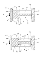
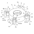
図5は、ベーンロータ7の斜視図、図6は、リアプレート12側から見たときのベーンロータ7の正面図、図7は、図3の線A-Aに沿って切断したバルブタイミング制御装置の断面図である。
上述したように、第2~第4ベーン15b~15dには、同様の形状に形成された第1、第2凹部23,24を有している。以下では、代表して第2ベーン15bの第1、第2凹部23,24について説明する。
図5および図7に示すように、第2ベーン15bの第2側面22には、ベーン他端面20bから第2ベーン15bの軸方向中央部よりもベーン一端面20a側の位置までの領域に、第2側面22に対し矩形に凹む第2凹部24が形成されている。また、第2凹部24は、図5および図6に示すように、ロータ部14と第2ベーン15bとの連結部38寄りの位置に形成されている。第2凹部24は、図5に示すように、第2側面22側から見たときの形状が軸方向に沿った長辺を有する長方形をなしている。第2凹部24は、遅角油圧室9と連通しており、該遅角油圧室9内の作動油が第2凹部24内に供給されるようになっている。また、第2凹部24の軸方向一端側の端部である一端部24aが、ベーン一端面20aおよびベーン他端面20bと平行で、かつ油圧を受ける概ね長方形の平坦な面である受圧面24bによって閉塞されており、軸方向他端側の端部である他端部24cがベーン他端面20bに開口し、リアプレート12の内端面12cに対向するようになっている。第2凹部24の深さは、第1側面21と第2側面22との間の長さである第2ベーン15bの幅の半分よりも小さく形成されている。
また、第1側面21には、ベーン他端面20bから第2ベーン15bの軸方向中央部よりもベーン一端面20a側の位置までの領域、つまりベーンロータ7の周方向において第2凹部24とオーバーラップする領域に、第2凹部24と同様の形状を有する第1凹部23が形成されている。第1凹部23は、進角油圧室10と連通しており、該進角油圧室10内の作動油が第1凹部23内に供給されるようになっている。第2凹部24と同様に、第1凹部23の軸方向一端側の端部である一端部23aが、ベーン一端面20aおよびベーン他端面20bと平行で、かつ油圧を受ける概ね長方形の平坦な面である受圧面23bによって閉塞されており、軸方向他端側に位置する他端部23cが開口し、リアプレート12の内端面12cに対向するようになっている。
[バルブタイミング制御装置の作動]
まず、機関始動時は、図3に示すように、コイルスプリング36のばね力によってベーンロータ7を最大進角位置に付勢している。この位置で予めロックピン34の先端部34aが、ロック穴35に挿入されて、ベーンロータ7を始動に最適な進角側の相対回転位置に拘束している。
まず、機関始動時は、図3に示すように、コイルスプリング36のばね力によってベーンロータ7を最大進角位置に付勢している。この位置で予めロックピン34の先端部34aが、ロック穴35に挿入されて、ベーンロータ7を始動に最適な進角側の相対回転位置に拘束している。
そして、機関始動後の例えば低回転負荷域では、電子コントローラにより電磁切換弁28のコイルへの非通電状態が維持される。これによって、オイルポンプ27の吐出通路27aと遅角油通路25を連通させると同時に、進角油通路26とドレン通路29を連通させる。
このため、オイルポンプ27から吐出された作動油は、遅角油通路25を介して各遅角油圧室9内に流入して、各遅角油圧室9が高圧になる。一方、各進角油圧室10内の作動油が進角油通路26を通ってドレン通路29からオイルパン30内に排出されて、各進角油圧室10内が低圧になる。
このとき、各遅角油圧室9内に流入した作動油が解除用油圧回路から受圧室37およびロック穴35内にも流入して高圧となり、これによりロックピン34が後退動して先端部34aがロック穴35から抜け出して、ベーンロータ7の自由な回転が確保される。
従って、各遅角油圧室9の容積の拡大に伴い、ベーンロータ7が、図4に示すように遅角側へ回転して第1ベーン15aの第1側面21が周方向から対向する第1シュー8aの対向一側面に当接して最大遅角側の回転位置が規制される。これにより、ベーンロータ7、つまりカムシャフト2は、ハウジング6に対して相対回転角度が最遅角側に変換される。
次に、機関が例えば高回転高負荷域に移行した場合は、電子コントローラから電磁切換弁28に制御電流が出力されて、吐出通路27aと進角油通路26を連通させると同時に、遅角油通路25とドレン通路29を連通させる。これにより、遅角油通路25内の作動油が排出されて低圧になると共に、進角油圧室10内に作動油が供給されて内部が高圧になる。このとき、進角油圧室10から上記解除用油圧回路を介して受圧室37内に油圧が供給されることから、この油圧によってロックピン34はロック穴35から抜け出した状態が維持される。
このため、ベーンロータ7は、図3に示すように、ハウジング6に対して進角側へ回転して第1ベーン15aの第2側面22が周方向から対向する第2シュー8bの対向一側面に当接して最大進角側の回転位置が規制される。これによって、カムシャフト2のハウジング6に対する相対回動位置が最進角側に変換される。この結果、排気弁の開閉タイミングが最進角側に制御されて、かかる高回転高負荷域における機関の出力を向上させることができる。
[第1実施形態の作用効果]
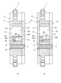
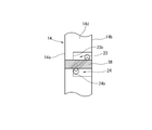
図8(a)は受圧面23b,24bに油圧が作用する前のバルブタイミング制御装置の断面図、図8(b)は受圧面23b,24bに油圧が作用しているときのバルブタイミング制御装置の断面図である。
図8(a)は受圧面23b,24bに油圧が作用する前のバルブタイミング制御装置の断面図、図8(b)は受圧面23b,24bに油圧が作用しているときのバルブタイミング制御装置の断面図である。
まず、図8(a)では、遅角油圧室9の内圧および進角油圧室10の内圧が、第2ベーン15bのベーン一端面20aとフロントプレート11の内端面11fとの間のサイドクリアランス16の内圧よりも高くなっている。
また、この状態では、図1に示すようなロックピン34とロック穴35との係り合わせが解除され、ベーンロータ7が、遅角油圧室9および進角油圧室10に選択的に供給される油圧によって周方向(図8(a)の上下方向)に移動可能になっている。
そして、カムシャフト2に例えば正の交番トルクが生じると、第2ベーン15bが、図8(a)に矢印Gで示すように最進角側へ振られ、進角油圧室10の容積が広くなり、一方、遅角油圧室9の容積が狭くなる。つまり、カムシャフト2の正の交番トルクに起因して、進角油圧室10の内圧が小さくなり、一方、遅角油圧室9の内圧が高くなる。このため、遅角油圧室9と進角油圧室10との間に差圧が発生し、図8(a)に矢印Hで示すように、遅角油圧室9からサイドクリアランス16を通って進角油圧室10へと連続する作動油の流れが生じる。
また、第2ベーン15bの第1、第2凹部23,24には、進角油圧室10および遅角油圧室9からの作動油がそれぞれ供給されている。第1、第2凹部23,24内の作動油により、第1、第2凹部23,24の受圧面23b,24bには、図8(b)に矢印Iで示すように、リアプレート12側からフロントプレート11側に向かって軸方向に油圧が作用する。この油圧Iにより、ベーンロータ7が軸方向に沿ってフロントプレート11側へ移動し、第2ベーン15bのベーン一端面20aがフロントプレート11の内端面11fに押し付けられる。これにより、ベーン一端面20aと内端面11fとの間にフリクションが発生して、このフリクションによって、第2ベーン15bはフロントプレート11に対する自由な回転が規制される。よって、内燃機関の望ましい相対角の規定位置でバルブタイミングが維持され、内燃機関の性能を向上させることができる。
仮にベーンロータ7の移動量が軸方向に沿ったサイドクリアランス16の幅よりも小さい場合には、油圧が、図8(b)に破線の矢印Qで示すように、リアプレート12の内端面12cに作用する。これによって、リアプレート12が、ハウジング本体6a(図1等参照)を介して接続されるフロントプレート11と共に第2ベーン15bから離間する方向へ移動する。従って、フロントプレート11の内端面11fが第2ベーン15bのベーン一端面20aに押し付けられる。よって、このようにベーンロータ7に対して軸方向に相対移動が可能なフロントプレート11が移動することによっても、第2ベーン15bはフロントプレート11に対する自由な回転が規制され、内燃機関の性能を向上させることができる。
また、本実施形態では、第1凹部23および第2凹部24は、ベーンロータ7の周方向において互いにオーバーラップしている。つまり、第1凹部23および第2凹部24は、比較的広い範囲に亘って連続する第1、第2側面21,22において、ベーンロータ7の周方向において互いにオーバーラップするように形成されている。
仮に、第1、第2凹部23,24がベーンロータ7の周方向において互いにオーバーラップしないように形成されていると、第1、第2凹部23,24の進角油圧室10および遅角油圧室9への開口面積が狭くなってしまう。これにより、第1、第2凹部23,24内へ作動油が流れ込み難くなり、受圧面23b,24bに油圧が作用するのが遅くなる、つまり油圧の応答性が悪化する虞がある。
このため、本実施形態では、第1、第2凹部23,24を周方向にオーバーラップさせて、第1、第2凹部23,24の進角油圧室10および遅角油圧室9への開口面積を広く確保することで、第1、第2凹部23,24内へ作動油の流れを促進し、油圧の応答性を向上させている。これにより、第2ベーン15bのベーン一端面20aがフロントプレート11の内端面11fに当接し易くなり、内燃機関の性能を向上させることができる。
[第2実施形態]
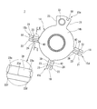
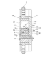
図9は本発明の第2実施形態を示し、リアプレート12側から見たときのベーンロータ7の正面図である。図10(a)は図9の線B-Bに沿って切断したベーンロータ7等の断面図、図10(b)は図9の線C-Cに沿って切断したベーンロータ7等の断面図である。なお、図10(a)および図10(b)は、ハウジング6内に収容された状態のベーンロータ7等の断面図として示してある。
図9は本発明の第2実施形態を示し、リアプレート12側から見たときのベーンロータ7の正面図である。図10(a)は図9の線B-Bに沿って切断したベーンロータ7等の断面図、図10(b)は図9の線C-Cに沿って切断したベーンロータ7等の断面図である。なお、図10(a)および図10(b)は、ハウジング6内に収容された状態のベーンロータ7等の断面図として示してある。
第2実施形態では、第1凹部23と第2凹部24とが、ベーンロータ7の径方向において互い違いになるように設けられている。つまり、第1凹部23と第2凹部24とは、ベーンロータ7の周方向にオーバーラップしないように設けられている。
第1凹部23は、径方向においてシール溝18付近に位置しており、第1側面21に対し矩形に凹むように形成されている。径方向に沿った本実施形態の第1凹部23の幅は、径方向に沿った第1実施形態の第1凹部23の幅よりも小さくなっている。また、本実施形態の第1凹部23の深さは、第1側面21と第2側面22との間の長さである第2ベーン15bの幅の半分よりも大きく、第1実施形態の第1凹部23の深さよりも深くなっている。これに伴い、本実施形態の第1凹部23の受圧面23bの受圧面積は、第1実施形態の第1凹部23の受圧面23bの受圧面積よりも大きくなっている。
また、第2凹部24は、第1凹部23と同様の形状を有しており、第2側面22のうち連結部38よりの位置に、第2側面22に対し矩形に凹むように形成されている。第1凹部23と同様に、径方向に沿った本実施形態の第2凹部24の幅は、径方向に沿った第1実施形態の第2凹部24の幅よりも小さくなっている。同じく、本実施形態の第2凹部24の深さは、第1実施形態の第2凹部24の深さよりも深くなっており、本実施形態の第2凹部24の受圧面24bの受圧面積は、第1実施形態の第2凹部24の受圧面24bの受圧面積よりも大きくなっている。
[第2実施形態の作用効果]
上記のように構成された本実施形態のベーンロータ7によっても、受圧面23b,24bに油圧が作用し、第2ベーン15bのベーン一端面20aがフロントプレート11の内端面11fに押し付けられる。これによって、バルブタイミング制御装置の作動時において、カムシャフト2の交番トルクに起因する第2ベーン15bの周方向の振れを抑制し、内燃機関の性能を向上させることができる。
[第2実施形態の作用効果]
上記のように構成された本実施形態のベーンロータ7によっても、受圧面23b,24bに油圧が作用し、第2ベーン15bのベーン一端面20aがフロントプレート11の内端面11fに押し付けられる。これによって、バルブタイミング制御装置の作動時において、カムシャフト2の交番トルクに起因する第2ベーン15bの周方向の振れを抑制し、内燃機関の性能を向上させることができる。
[第3実施形態]
図11は本発明の第3実施形態を示し、リアプレート12側から見たときのベーンロータ7の正面図、図12は図11の線D-Dに沿って切断したベーンロータ7の断面図である。
図11は本発明の第3実施形態を示し、リアプレート12側から見たときのベーンロータ7の正面図、図12は図11の線D-Dに沿って切断したベーンロータ7の断面図である。
第3実施形態では、第1、第2凹部23,24が、第2~第4ベーン15b~15dではなく、ロータ部14の軸方向他端側の端面であるロータ部他端面14bに開口形成されている。
第1凹部23は、ベーンロータ7の周方向において第2ベーン15bの連結部38と隣接する位置に、ロータ部他端面14bに対し矩形に凹むように形成されている。図11に示すように、軸方向から見たときの第1凹部23の形状は、概ね正方形をなしている。第1凹部23は、ロータ部他端面14bに開口すると共に、ロータ部14の外周面14dに開口している。
第2凹部24は、第1凹部23と同様の形状を有しており、ベーンロータ7の周方向において連結部38を挟んで第1凹部23とは反対側の位置に、ロータ部他端面14bに対し矩形に凹むように形成されている。第1凹部23と同様に、第2凹部24は、軸方向から見たときの形状が概ね正方形をなし、ロータ部他端面14bおよび外周面14dに開口している。
[第3実施形態の作用効果]
上記のように、第3実施形態では、第1凹部23および第2凹部24は、ロータ部14の軸方向端面であるロータ部他端面14bに形成されている。
上記のように、第3実施形態では、第1凹部23および第2凹部24は、ロータ部14の軸方向端面であるロータ部他端面14bに形成されている。
このようにロータ部他端面14bに第1、第2凹部23,24を形成することにより、第2~第4ベーン15b~15dに第1、第2凹部23,24を形成しなくて済む。このため、第2~第4ベーン15b~15dのベーン他端面20bとリアプレート12の内端面12c(図8(a)および図8(b)等参照)との間のシール面を広く確保することができる。よって、ベーン他端面20bと内端面12cとの間のサイドクリアランスを通って漏れる作動油の量が減少し、ベーンロータ7を効率的に作動させることができる。
[第4実施形態]
図13は第4実施形態に供されるベーンロータ7の斜視図、図14はリアプレート12側から見たときのベーンロータ7の正面図、図15は図14の線E-Eに沿って切断したバルブタイミング制御装置の断面図である。
図13は第4実施形態に供されるベーンロータ7の斜視図、図14はリアプレート12側から見たときのベーンロータ7の正面図、図15は図14の線E-Eに沿って切断したバルブタイミング制御装置の断面図である。
第4実施形態では、図13~図15に示すように、第1、第2凹部23,24に、リアプレート12の内端面12cと第2ベーン15bのベーン他端面20bとの間の後述するサイドクリアランス43(図18(a)参照)からの作動油の漏れを抑制する第1、第2部材である第1、第2漏れ抑制部材39,40がそれぞれ設けられている。第1、第2漏れ抑制部材39,40は、金属により同様の形状に形成されている。また、図15に示すように、軸方向に沿って延びる板状の板状部41と、該板状部41と直交するように板状部41から径方向に突出形成された概ね板状のフランジ部42とをそれぞれ有している。つまり、第1、第2漏れ抑制部材39,40は、第1、第2凹部23,24の底面23d,24dと軸方向に摺動可能に設けられた板状部41と、該板状部41から径方向に突出形成され、リアプレート12の内端面12cと当接可能なフランジ部42とをそれぞれ有している。第1、第2漏れ抑制部材39,40は、第1、第2凹部23,24に供給された油圧がフランジ部42に作用することによりリアプレート12側に摺動し、これにより、フランジ部42がリアプレート12の内端面12cに当接して作動油に対するシール機能を発揮するように構成されている。
図16は第1、第2漏れ抑制部材39,40の斜視図、図17(a)は第1、第2漏れ抑制部材39,40の正面図、図17(b)は第1、第2漏れ抑制部材39,40の上面図、図17(c)は第1、第2漏れ抑制部材39,40の側面図である。
第1、第2漏れ抑制部材39,40は同様の形状を有するので、以下に、代表して第1漏れ抑制部材39について説明する。なお、図16および図17(a)~図17(c)には、第2漏れ抑制部材40の符号を括弧内に示してある。
板状部41は、図17(a)に示すように概ね長方形をなしており、フランジ部42が突出形成された第1面41aと、該第1面41aの裏側に位置する面であり、第1凹部23の底面23dと摺動可能な第2面41bと、第1、第2面41a,41bと直交し、リアプレート12の内端面12cに当接可能な第3面41cと、該第3面41cと平行な第4面41dと、第3、第4面41c,41dと直交する第5、第6面41e,41fとを有している。第4面41dは、該第4面41dに対し第3面41c側へ傾斜した一対の面取り部41g,41gを介して第5、第6面41e,41fに接続されている。第5、第6面41e,41fを含む板状部41の一対の側部41h,41hは、第1凹部23の一対の側面23e,23eのうち底面23dと隣接する部位に形成された一対の溝部23f,23fにそれぞれ嵌め込まれる(図14参照)。側部41h,41hは、第1凹部23内に供給された油圧がフランジ部42に作用したときに軸方向に沿って移動可能となるように溝部23f,23f内に所定の隙間を介して配置される。
フランジ部42は、径方向に沿った板状部41の長さ(図17(a)の左右方向の長さ)よりも短い長さを有しており、板状部41の第1面41aのうち第3面41cに隣接する位置から板状部41と直交するように立ち上がっている。フランジ部42は、第1凹部23に供給された油圧を受ける傾斜した受圧面42aと、該受圧面42aに油圧が作用し、第1漏れ抑制部材39がリアプレート12側に移動したときにリアプレート12の内端面12cと当接する当接面42bとを有している。受圧面42aは、図17(c)に示すように、第1面41aから離間するにつれてフランジ部42の厚み(図17(c)の上下方向の厚み)が漸次減少するように傾斜している。当接面42bは、板状部41の第3面41cと連続した平坦な面であり、当接面42bがリアプレート12の内端面12cに当接した際に該第3面41cと共に内端面12cに当接するようになっている。
[第4実施形態の作用効果]
図18(a)は受圧面23b,24b,42a,42aに油圧が作用する前のバルブタイミング制御装置の断面図、図18(b)は受圧面23b,24b,42a,42aに油圧が作用しているときのバルブタイミング制御装置の断面図である。
図18(a)は受圧面23b,24b,42a,42aに油圧が作用する前のバルブタイミング制御装置の断面図、図18(b)は受圧面23b,24b,42a,42aに油圧が作用しているときのバルブタイミング制御装置の断面図である。
まず、図18(a)では、遅角油圧室9の内圧および進角油圧室10の内圧が、ベーン一端面20aと内端面11fとの間のサイドクリアランス16の内圧、およびベーン他端面20bと内端面12cとの間のサイドクリアランス43の内圧よりも高くなっている。
また、図18(a)では、図1に示すようなロックピン34とロック穴35との係り合わせが解除され、ベーンロータ7が、遅角油圧室9および進角油圧室10に選択的に供給される油圧によって周方向(図18(a)の上下方向)に移動するようになっている。
そして、カムシャフト2に例えば正の交番トルクが生じると、第2ベーン15bが、図18(a)に矢印Gで示すように最進角側へ振られ、進角油圧室10の容積が広くなり、一方、遅角油圧室9の容積が狭くなる。つまり、カムシャフト2の正の交番トルクに起因して、進角油圧室10の内圧が小さくなり、一方、遅角油圧室9の内圧が高くなる。このため、遅角油圧室9と進角油圧室10との間に差圧が発生し、遅角油圧室9からサイドクリアランス16を通って進角油圧室10へと連続する作動油の流れ(矢印H)に加えて、遅角油圧室9からサイドクリアランス43を通って進角油圧室10へと連続する作動油の流れ(矢印J)が生じる。
また、第2ベーン15bの第1、第2凹部23,24には、進角油圧室10および遅角油圧室9から油圧がそれぞれ供給されている。従って、第1、第2凹部23,24の受圧面23b,24bに軸方向に沿った油圧Iが作用することに加えて、第1、第2漏れ抑制部材39,40の受圧面42a,42aに、油圧が、図18(b)に矢印Kで示すように、軸方向に沿ってフロントプレート11側からリアプレート12側へ作用する。この油圧Kにより、第1、第2漏れ抑制部材39,40が軸方向に沿ってリアプレート12側へ移動し、フランジ部42の当接面42bが板状部41の第3面41cと共にリアプレート12の内端面12cに押し付けられる。これにより、当接面42bおよび第3面41cと内端面12cとの間にフリクションが発生し、第2ベーン15bが、リアプレート12に保持される。よって、内燃機関の望ましい作動を達成するための規定位置でバルブタイミングが維持され、排気ガスの量が減少し、内燃機関の性能を向上させることができる。
また、本実施形態では、当接面42bおよび第3面41cと内端面12cとの当接によりサイドクリアランス43がシールされる。これにより、作動油が遅角油圧室9からサイドクリアランス43を通って進角油圧室10へと漏れること(矢印J)を抑制することができる。
[第5実施形態]
図19および図20は本発明の第5実施形態を示し、図19は第1、第2漏れ抑制部材39,40の正面図、図20は第1、第2漏れ抑制部材39,40を装着した状態の第5実施形態のベーンロータ7の斜視図である。なお、図19では、第1漏れ抑制部材39と同様の形状を有する第2漏れ抑制部材40の符号を括弧内に示している。また、図20では、第2ベーン15bの内部における第2凹部24の形状を破線で示してある。
図19および図20は本発明の第5実施形態を示し、図19は第1、第2漏れ抑制部材39,40の正面図、図20は第1、第2漏れ抑制部材39,40を装着した状態の第5実施形態のベーンロータ7の斜視図である。なお、図19では、第1漏れ抑制部材39と同様の形状を有する第2漏れ抑制部材40の符号を括弧内に示している。また、図20では、第2ベーン15bの内部における第2凹部24の形状を破線で示してある。
第5実施形態では、第4実施形態の面取り部41g,41gが廃止され、第1、第2漏れ抑制部材39,40の各第5、第6面41e,41fは、フランジ部42側に向かうにつれて第5、第6面41e,41fの間の幅(図19の左右方向の幅)が漸次増加するように傾斜した面として形成されている。第5、第6面41e,41fは、フランジ部42に対して対称となるように形成されている。
ここで、以下の説明の便宜上、第2ベーン15bの第2側面22に形成された第2凹部24と、この第2凹部24に配置される第2漏れ抑制部材40とについて説明する。
本実施形態では、第2凹部24は、第2側面22およびベーン他端面20bに開口し、フランジ部42を収容するフランジ部収容部44と、該フランジ部収容部44と連通し、板状部41を収容する板状部収容部45とを有している。
フランジ部収容部44は、第2側面22側から見たときの形状が概ね正方形をなしており、ベーンロータ7の軸方向に沿った長さが、第1、第4実施形態の第2凹部24の軸方向に沿った長さよりも短くなっている。フランジ部収容部44は、軸方向一端側に位置する一端部44aが、ベーン一端面20aおよびベーン他端面20bと平行で、かつ油圧を受ける平坦な面である受圧面44bによって閉塞されており、軸方向他端側に位置する他端部44cがベーン他端面20bに開口している。一端部44aと他端部44cとの間の距離は、軸方向に沿ったフランジ部42の高さ(図19の上下方向の高さ)よりも長くなっており、これにより、フランジ部42が一端部44aと他端部44cとの間で軸方向へ移動可能となっている。また、フランジ部収容部44には、受圧面44bの両端からベーン他端面20bまで軸方向に沿って連続する一対の面44d,44eが設けられている。面44d,44eの間の距離は、径方向に沿ったフランジ部42の幅(図19の左右方向の幅)よりも大きくなっており、これにより、フランジ部42が面44d,44eの間で径方向へ移動可能となっている。
板状部収容部45は、フランジ部収容部44よりも第2ベーン15bの内部側に形成されており、第2側面22側から見たときの形状がフランジ部収容部44よりも大きな概ね矩形状をなしている。板状部収容部45は、軸方向一端側に位置する一端部45aが、ベーン一端面20aおよびベーン他端面20bと平行な面である面45bによって閉塞されており、軸方向他端側に位置する他端部45cがベーン他端面20bに開口している。一端部45aと他端部45cとの間の距離は、軸方向に沿った板状部41の高さ(図19の上下方向の高さ)よりも長くなっており、これにより、板状部41が一端部45aと他端部45cとの間で軸方向へ移動可能となっている。また、板状部収容部45には、面45bのロータ部14側の端部からベーン他端面20bまで軸方向に沿って連続する面45dと、面45bのシール溝18側の端部からベーン他端面20bまで板状部41の第6面41fと同じ傾斜角度で傾斜する傾斜面45eとが設けられている。面45dと傾斜面45eとの間の最大距離は、傾斜した第5、第6面41e,41fの間の最大距離よりも長くなっており(図21(a)および図21(b)参照)、これにより、板状部41が第5、第6面41e,41fの間で径方向へ移動可能となっている。
[第5実施形態の作用効果]
図21(a)はベーンロータ7の非回転時であり、遠心力が第2漏れ抑制部材40に作用していない状態を示す説明図、図21(b)はベーンロータ7の回転時であり、遠心力が第2漏れ抑制部材40に作用している状態を示す説明図である。図21(a)および図21(b)では、板状部収容部45の面45b,45dおよび傾斜面45eのみを示してある。
図21(a)はベーンロータ7の非回転時であり、遠心力が第2漏れ抑制部材40に作用していない状態を示す説明図、図21(b)はベーンロータ7の回転時であり、遠心力が第2漏れ抑制部材40に作用している状態を示す説明図である。図21(a)および図21(b)では、板状部収容部45の面45b,45dおよび傾斜面45eのみを示してある。
ベーンロータ7の非回転時には、図21(a)に示すように、板状部41は、板状部収容部45の中央に位置しており、傾斜した第6面41fが傾斜面45eから径方向に離間した位置にある。
そして、ベーンロータ7が回転すると、図21(b)に矢印Xで示すように、第2漏れ抑制部材40に径方向外側へ向かう遠心力が作用することにより、第2漏れ抑制部材40が、図21(b)に矢印Yで示すように傾斜面45e側に移動する。これにより、板状部41の傾斜した第6面41fは、傾斜面45eに当接し、該傾斜面45eによって図21(b)に矢印Zで示すようにガイドされ、破線で示すリアプレート12の内端面12cに当接する。従って、第6面41fと内端面12cとの当接により、両者の間の図示省略したサイドクリアランスがシールされる。
従って、第5実施形態においても、第4実施形態と同様に、サイドクリアランスを介した作動油の漏れを抑制することができる。
[第6実施形態]
図22は第6実施形態に供されるベーンロータ7の斜視図、図23は第1、第2漏れ抑制部材39,40および第6実施形態の板ばね46の斜視図、図24は第2漏れ抑制部材40および板ばね46を組み付けた状態の第6実施形態のベーンロータ7の部分斜視図である。なお、図22および図24では、第2ベーン15bの内部における第2凹部24の形状を破線で示してある。
図22は第6実施形態に供されるベーンロータ7の斜視図、図23は第1、第2漏れ抑制部材39,40および第6実施形態の板ばね46の斜視図、図24は第2漏れ抑制部材40および板ばね46を組み付けた状態の第6実施形態のベーンロータ7の部分斜視図である。なお、図22および図24では、第2ベーン15bの内部における第2凹部24の形状を破線で示してある。
第6実施形態では、第5実施形態の板状部収容部45の傾斜面45eが廃止され、板状部収容部45は、面45bと直交する面45fを有している。また、板状部収容部45の面45dと面45fとの間の距離は、径方向に沿った第1、第2漏れ抑制部材39,40の幅(図23の左右方向の幅)よりも僅かに短くなっている。一方、板状部収容部45の一端部45aと他端部45cとの間の距離は、軸方向に沿った第1、第2漏れ抑制部材39,40の高さよりも大きくなっている。
以下、説明の便宜上、第2漏れ抑制部材40と、該第2漏れ抑制部材40に適用される板ばね46について説明する。
図24に示すように、第2漏れ抑制部材40の板状部41の第4面41dと板状部収容部45の面45bとの間には、金属製の薄板から形成されており、図示せぬリアカバーの内端面に対し第2漏れ抑制部材40を付勢する付勢部材である板ばね46が圧縮状態で設けられている。板ばね46は、第4面41dから離間するように円弧状に湾曲する円弧状部47と、該円弧状部47の両端部47a,47aから、第4面41dから離間するように折り曲げられた一対の折曲部48,48とを有している。
円弧状部47は、図24に示すように、中央部47bが面45bと弾性的に当接し、さらに、両端部47a,47aが第4面41dのうち面取り部41g,41g付近の部位に弾性的に当接することにより、軸方向に弾性変形が可能となるように構成されている。
折曲部48,48は、先端部48a,48aが板状部収容部45の面45d,45fにそれぞれ弾性的に当接することで第2漏れ抑制部材40の径方向の移動を規制している。
[第6実施形態の作用効果]
上記のように、本実施形態では、受圧面42aに作用する油圧に加えて、板ばね46の付勢力によって図示省略したリアカバーの内端面に第2漏れ抑制部材40を押し付けるようにしたことから、第4、第5実施形態と比べて大きい押圧力でもって、第3面41cおよび当接面42bがリアカバーの内端面に押し付けられる。これにより、バルブタイミング制御装置の作動時において、カムシャフト2の交番トルクに起因するベーンロータ7の振れが効果的に抑制され、内燃機関の性能を効果的に向上させることができる。
上記のように、本実施形態では、受圧面42aに作用する油圧に加えて、板ばね46の付勢力によって図示省略したリアカバーの内端面に第2漏れ抑制部材40を押し付けるようにしたことから、第4、第5実施形態と比べて大きい押圧力でもって、第3面41cおよび当接面42bがリアカバーの内端面に押し付けられる。これにより、バルブタイミング制御装置の作動時において、カムシャフト2の交番トルクに起因するベーンロータ7の振れが効果的に抑制され、内燃機関の性能を効果的に向上させることができる。
なお、上記各実施形態では、受圧面23b,24bがベーン一端面20aおよびベーン他端面20bと平行な面として構成された例を開示したが、ベーン一端面20aおよびベーン他端面20bに対し受圧面を傾斜させた構成も、本発明に適用することができる。
また、上記各実施形態では、ベーンロータ7がカムシャフト2の正の交番トルクに起因して進角油圧室10側から遅角油圧室9側へ振られる例を開示したが、ベーンロータ7がカムシャフト2の負の交番トルクに起因して遅角油圧室9側から進角油圧室10側へ振られる例も本発明に適用することができる。この場合、サイドクリアランス16,43内の作動油の流れは進角油圧室10側から遅角油圧室9へと通流する。
さらに、上記各実施形態では、第1、第2凹部23,24内に第1、第2漏れ抑制部材39,40をそれぞれ設けた例を開示したが、第1、第2凹部23,24を形成せずに第1、第2漏れ抑制部材39,40を設けるようにしても良い。この場合には、第1、第2側面21,22に軸方向に沿って連続する案内溝を形成し、さらに、第1、第2漏れ抑制部材39,40の第2面41bに上記案内溝に沿って案内される突出部を形成する。
また、上記第6実施形態では、付勢部材として板ばね46を用いた例を開示したが、他の付勢部材、例えばコイルスプリングを用いるようにしても良い。
また、上記各実施形態では排気側カムシャフトに用いられるバルブタイミング制御装置を示したが、吸気側カムシャフトに用いても良い。
以上説明した実施形態に基づく内燃機関のバルブタイミング制御装置としては、例えば以下に述べる態様のものが考えられる。
内燃機関のバルブタイミング制御装置は、その一態様として、クランクシャフトからの回転力が伝達されるハウジングと、前記ハウジング内に配置されると共にカムシャフトに固定されるベーンロータであって、前記ハウジング内の作動室を第1油圧室と第2油圧室とに区切るベーンを有し、前記第1油圧室または前記第2油圧室に油圧が作用することにより前記ハウジングに対して相対回転可能なベーンロータと、前記ベーンロータに設けられ、前記第1油圧室と連通する第1凹部であって、前記ベーンロータの回転軸線の方向において一対の端部を有し、該一対の端部のうち一端部が閉塞され、他端部が開口した第1凹部と、前記ベーンロータに設けられ、前記第2油圧室と連通する第2凹部であって、前記ベーンロータの回転軸線の方向において一対の端部を有し、該一対の端部のうち一端部が閉塞され、他端部が開口した第2凹部と、を備える。
前記バルブタイミング制御装置の好ましい態様において、前記ベーンは、前記第1油圧室に対向する第1側面と、前記第2油圧室に対向する第2側面とを有し、前記第1凹部は、前記第1側面に凹むように設けられ、前記第2凹部は、前記第2側面に凹むように設けられている。
別の好ましい態様では、前記バルブタイミング制御装置の態様のいずれかにおいて、前記第1凹部の一端部および前記第2凹部の一端部は、油圧が作用する受圧面を有する。
別の好ましい態様では、前記バルブタイミング制御装置の態様のいずれかにおいて、前記第1凹部および前記第2凹部は、前記ベーンロータの回転軸線周りの方向である周方向において互いにオーバーラップしている。
別の好ましい態様では、前記バルブタイミング制御装置の態様のいずれかにおいて、前記第1凹部および前記第2凹部は、前記ベーンロータの回転軸線と直交する方向である径方向において互い違いに設けられている。
別の好ましい態様では、前記バルブタイミング制御装置の態様のいずれかにおいて、前記ベーンロータは、前記ベーンと一体に形成されると共に前記カムシャフトに固定される円筒状のロータ部を有し、前記第1凹部および前記第2凹部は、前記ロータ部の軸方向端面に形成されている。
別の好ましい態様では、前記バルブタイミング制御装置の態様のいずれかにおいて、前記第1凹部および前記第2凹部は、前記ロータ部の軸方向端面のうち前記ベーンと前記ロータ部との連結部付近に形成されている。
また、以上説明した実施形態に基づく内燃機関の別のバルブタイミング制御装置としては、例えば以下に述べる態様のものが考えられる。
内燃機関のバルブタイミング制御装置は、その一態様として、クランクシャフトからの回転力が伝達されるハウジングと、前記ハウジング内に配置されると共にカムシャフトに固定されるベーンロータであって、前記ハウジング内の作動室を第1油圧室と第2油圧室とに区切るベーンを有し、前記第1油圧室または前記第2油圧室に油圧が作用することにより前記ハウジングに対して相対回転可能なベーンロータと、前記ベーンロータに配置され、前記第1油圧室の油圧によって前記ハウジングに押し付けられる第1部材と、前記ベーンロータに配置され、前記第2油圧室の油圧によって前記ハウジングに押し付けられる第2部材と、を有する。
前記バルブタイミング制御装置の好ましい態様において、前記第1部材および前記第2部材は、前記ベーンロータの回転軸線の方向に沿って移動可能となるように前記ベーンに保持されている。
別の好ましい態様では、前記バルブタイミング制御装置の態様のいずれかにおいて、前記ベーンは、前記第1油圧室と連通し、前記ベーンロータの回転軸線の方向において一対の端部を有し、該一対の端部のうち一端部が閉塞され、他端部が開口する第1凹部と、前記第2油圧室と連通し、前記ベーンロータの回転軸線の方向において一対の端部を有し、該一対の端部のうち一端部が閉塞され、他端部が開口する第2凹部とを有し、前記第1部材および前記第2部材は、前記第1凹部および前記第2凹部にそれぞれ配置されると共に、前記第1凹部の他端部および前記第2凹部の他端部において前記ハウジングに当接可能なフランジ部をそれぞれ有する。
別の好ましい態様では、前記バルブタイミング制御装置の態様のいずれかにおいて、前記第1部材は、前記第1凹部に保持され、前記ベーンロータの回転軸線の方向に延びる板状部と、該板状部から前記回転軸線の方向と直交するように延びる前記フランジ部とを有し、前記板状部は、前記回転軸線に対する径方向外側の端面に、前記フランジ部側に向かうほど前記回転軸線と直交する方向である径方向に沿った幅が漸次増加する傾斜面を有し、前記第1凹部は、前記傾斜面に当接可能な当接面を有する。
別の好ましい態様では、前記バルブタイミング制御装置の態様のいずれかにおいて、前記第1凹部には、前記ハウジングに前記第1部材を押し付ける第1付勢部材が設けられ、前記第2凹部には、前記ハウジングに前記第2部材を押し付ける第1付勢部材が設けられる。
Claims (12)
- クランクシャフトからの回転力が伝達されるハウジングと、
前記ハウジング内に配置されると共にカムシャフトに固定されるベーンロータであって、前記ハウジング内の作動室を第1油圧室と第2油圧室とに区切るベーンを有し、前記第1油圧室または前記第2油圧室に油圧が作用することにより前記ハウジングに対して相対回転可能なベーンロータと、
前記ベーンロータに設けられ、前記第1油圧室と連通する第1凹部であって、前記ベーンロータの回転軸線の方向において一対の端部を有し、該一対の端部のうち一端部が閉塞され、他端部が開口した第1凹部と、
前記ベーンロータに設けられ、前記第2油圧室と連通する第2凹部であって、前記ベーンロータの回転軸線の方向において一対の端部を有し、該一対の端部のうち一端部が閉塞され、他端部が開口した第2凹部と、
を備える内燃機関のバルブタイミング制御装置。 - 請求項1に記載の内燃機関のバルブタイミング制御装置において、
前記ベーンは、前記第1油圧室に対向する第1側面と、前記第2油圧室に対向する第2側面とを有し、
前記第1凹部は、前記第1側面に凹むように設けられ、
前記第2凹部は、前記第2側面に凹むように設けられていることを特徴とする内燃機関のバルブタイミング制御装置。 - 請求項2に記載の内燃機関のバルブタイミング制御装置において、
前記第1凹部の一端部および前記第2凹部の一端部は、油圧が作用する受圧面を有することを特徴とする内燃機関のバルブタイミング制御装置。 - 請求項2に記載の内燃機関のバルブタイミング制御装置において、
前記第1凹部および前記第2凹部は、前記ベーンロータの回転軸線周りの方向である周方向において互いにオーバーラップしていることを特徴とする内燃機関のバルブタイミング制御装置。 - 請求項2に記載の内燃機関のバルブタイミング制御装置において、
前記第1凹部および前記第2凹部は、前記ベーンロータの回転軸線と直交する方向である径方向において互い違いに設けられていることを特徴とする内燃機関のバルブタイミング制御装置。 - 請求項1に記載の内燃機関のバルブタイミング制御装置において、
前記ベーンロータは、前記ベーンと一体に形成されると共に前記カムシャフトに固定される円筒状のロータ部を有し、
前記第1凹部および前記第2凹部は、前記ロータ部の軸方向端面に形成されていることを特徴とする内燃機関のバルブタイミング制御装置。 - 請求項6に記載の内燃機関のバルブタイミング制御装置において、
前記第1凹部および前記第2凹部は、前記ロータ部の軸方向端面のうち前記ベーンと前記ロータ部との連結部付近に形成されていることを特徴とする内燃機関のバルブタイミング制御装置。 - クランクシャフトからの回転力が伝達されるハウジングと、
前記ハウジング内に配置されると共にカムシャフトに固定されるベーンロータであって、前記ハウジング内の作動室を第1油圧室と第2油圧室とに区切るベーンを有し、前記第1油圧室または前記第2油圧室に油圧が作用することにより前記ハウジングに対して相対回転可能なベーンロータと、
前記ベーンロータに配置され、前記第1油圧室の油圧によって前記ハウジングに押し付けられる第1部材と、
前記ベーンロータに配置され、前記第2油圧室の油圧によって前記ハウジングに押し付けられる第2部材と、
を備える内燃機関のバルブタイミング制御装置。 - 請求項8に記載の内燃機関のバルブタイミング制御装置において、
前記第1部材および前記第2部材は、前記ベーンロータの回転軸線の方向に沿って移動可能となるように前記ベーンに保持されていることを特徴とする内燃機関のバルブタイミング制御装置。 - 請求項9に記載の内燃機関のバルブタイミング制御装置において、
前記ベーンは、前記第1油圧室と連通し、前記ベーンロータの回転軸線の方向において一対の端部を有し、該一対の端部のうち一端部が閉塞され、他端部が開口する第1凹部と、前記第2油圧室と連通し、前記ベーンロータの回転軸線の方向において一対の端部を有し、該一対の端部のうち一端部が閉塞され、他端部が開口する第2凹部とを有し、
前記第1部材および前記第2部材は、前記第1凹部および前記第2凹部にそれぞれ配置されると共に、前記第1凹部の他端部および前記第2凹部の他端部において前記ハウジングに当接可能なフランジ部をそれぞれ有することを特徴とする内燃機関のバルブタイミング制御装置。 - 請求項10に記載の内燃機関のバルブタイミング制御装置において、
前記第1部材は、前記第1凹部に保持され、前記ベーンロータの回転軸線の方向に延びる板状部と、該板状部から前記回転軸線の方向と直交するように延びる前記フランジ部とを有し、
前記板状部は、前記回転軸線に対する径方向外側の端面に、前記フランジ部側に向かうほど前記回転軸線と直交する方向である径方向に沿った幅が漸次増加する傾斜面を有し、
前記第1凹部は、前記傾斜面に当接可能な当接面を有することを特徴とする内燃機関のバルブタイミング制御装置。 - 請求項10に記載の内燃機関のバルブタイミング制御装置において、
前記第1凹部には、前記ハウジングに前記第1部材を押し付ける第1付勢部材が設けられ、
前記第2凹部には、前記ハウジングに前記第2部材を押し付ける第2付勢部材が設けられることを特徴とする内燃機関のバルブタイミング制御装置。
Applications Claiming Priority (2)
| Application Number | Priority Date | Filing Date | Title |
|---|---|---|---|
| JP2018-231239 | 2018-12-11 | ||
| JP2018231239A JP2022034087A (ja) | 2018-12-11 | 2018-12-11 | 内燃機関のバルブタイミング制御装置 |
Publications (1)
| Publication Number | Publication Date |
|---|---|
| WO2020121635A1 true WO2020121635A1 (ja) | 2020-06-18 |
Family
ID=71075770
Family Applications (1)
| Application Number | Title | Priority Date | Filing Date |
|---|---|---|---|
| PCT/JP2019/039930 Ceased WO2020121635A1 (ja) | 2018-12-11 | 2019-10-10 | 内燃機関のバルブタイミング制御装置 |
Country Status (2)
| Country | Link |
|---|---|
| JP (1) | JP2022034087A (ja) |
| WO (1) | WO2020121635A1 (ja) |
Citations (5)
| Publication number | Priority date | Publication date | Assignee | Title |
|---|---|---|---|---|
| JPH0913920A (ja) * | 1995-06-30 | 1997-01-14 | Ofic Co | 可変バルブタイミング装置 |
| JPH11229828A (ja) * | 1998-02-09 | 1999-08-24 | Denso Corp | バルブタイミング調整装置 |
| JP2006090140A (ja) * | 2004-09-21 | 2006-04-06 | Hitachi Ltd | 内燃機関のバルブタイミング制御装置及びその組み付け方法 |
| JP2008184965A (ja) * | 2007-01-30 | 2008-08-14 | Toyota Motor Corp | 内燃機関の弁開閉時期制御装置 |
| JP2014532834A (ja) * | 2011-11-08 | 2014-12-08 | ゲーカーエン シンター メタルズ ホールディング ゲーエムベーハーGkn Sinter Metals Holding Gmbh | はめ込み型シーリング用溝形状を有する液圧式カムシャフト調節装置における複数部品から構成されるはめ込み型ローターならびにローターの製造方法 |
-
2018
- 2018-12-11 JP JP2018231239A patent/JP2022034087A/ja active Pending
-
2019
- 2019-10-10 WO PCT/JP2019/039930 patent/WO2020121635A1/ja not_active Ceased
Patent Citations (5)
| Publication number | Priority date | Publication date | Assignee | Title |
|---|---|---|---|---|
| JPH0913920A (ja) * | 1995-06-30 | 1997-01-14 | Ofic Co | 可変バルブタイミング装置 |
| JPH11229828A (ja) * | 1998-02-09 | 1999-08-24 | Denso Corp | バルブタイミング調整装置 |
| JP2006090140A (ja) * | 2004-09-21 | 2006-04-06 | Hitachi Ltd | 内燃機関のバルブタイミング制御装置及びその組み付け方法 |
| JP2008184965A (ja) * | 2007-01-30 | 2008-08-14 | Toyota Motor Corp | 内燃機関の弁開閉時期制御装置 |
| JP2014532834A (ja) * | 2011-11-08 | 2014-12-08 | ゲーカーエン シンター メタルズ ホールディング ゲーエムベーハーGkn Sinter Metals Holding Gmbh | はめ込み型シーリング用溝形状を有する液圧式カムシャフト調節装置における複数部品から構成されるはめ込み型ローターならびにローターの製造方法 |
Also Published As
| Publication number | Publication date |
|---|---|
| JP2022034087A (ja) | 2022-03-03 |
Similar Documents
| Publication | Publication Date | Title |
|---|---|---|
| CN102562202B (zh) | 内燃机的气门正时控制装置 | |
| CN103939165B (zh) | 内燃机的阀门正时控制装置及其组装方法 | |
| JP6368008B2 (ja) | 内燃機関のバルブタイミング制御装置 | |
| CN103046979A (zh) | 内燃机的气门正时控制装置 | |
| CN103726895B (zh) | 内燃机的气门正时控制装置 | |
| JP6267608B2 (ja) | 内燃機関のバルブタイミング制御装置 | |
| JPH09250310A (ja) | 内燃機関のバルブタイミング変更装置 | |
| JP3627340B2 (ja) | 弁開閉時期制御装置 | |
| JP2022034087A (ja) | 内燃機関のバルブタイミング制御装置 | |
| JP2009209719A (ja) | バルブタイミング調整装置 | |
| JP6157308B2 (ja) | 内燃機関のバルブタイミング制御装置 | |
| JPWO2017119234A1 (ja) | 内燃機関のバルブタイミング制御装置 | |
| JP2021004581A (ja) | 内燃機関のバルブタイミング制御装置 | |
| JP2020076383A (ja) | 内燃機関のバルブタイミング制御装置 | |
| JP2019044602A (ja) | 内燃機関のバルブタイミング制御装置 | |
| JPH1089021A (ja) | 内燃機関のバルブタイミング可変装置 | |
| JP6689665B2 (ja) | 内燃機関のバルブタイミング制御装置及び該バルブタイミング制御装置の組み付け方法 | |
| WO2018101155A1 (ja) | 内燃機関のバルブタイミング制御装置 | |
| CN113167141B (zh) | 内燃机的气门正时控制装置 | |
| JP7042155B2 (ja) | 内燃機関のバルブタイミング制御装置 | |
| WO2021125073A1 (ja) | 内燃機関のバルブタイミング制御装置 | |
| JP5895927B2 (ja) | バルブタイミング調整装置 | |
| CN114846224A (zh) | 内燃机的气门正时控制装置 | |
| JPH09303119A (ja) | 内燃機関のバルブタイミング可変装置 | |
| JPH09250312A (ja) | 内燃機関のバルブタイミング変更装置 |
Legal Events
| Date | Code | Title | Description |
|---|---|---|---|
| 121 | Ep: the epo has been informed by wipo that ep was designated in this application |
Ref document number: 19896582 Country of ref document: EP Kind code of ref document: A1 |
|
| NENP | Non-entry into the national phase |
Ref country code: DE |
|
| 122 | Ep: pct application non-entry in european phase |
Ref document number: 19896582 Country of ref document: EP Kind code of ref document: A1 |
|
| NENP | Non-entry into the national phase |
Ref country code: JP |