WO2020121454A1 - タンデム圧延機の制御装置 - Google Patents
タンデム圧延機の制御装置 Download PDFInfo
- Publication number
- WO2020121454A1 WO2020121454A1 PCT/JP2018/045752 JP2018045752W WO2020121454A1 WO 2020121454 A1 WO2020121454 A1 WO 2020121454A1 JP 2018045752 W JP2018045752 W JP 2018045752W WO 2020121454 A1 WO2020121454 A1 WO 2020121454A1
- Authority
- WO
- WIPO (PCT)
- Prior art keywords
- stands
- rolling mill
- tandem rolling
- drop amount
- value
- Prior art date
- Legal status (The legal status is an assumption and is not a legal conclusion. Google has not performed a legal analysis and makes no representation as to the accuracy of the status listed.)
- Ceased
Links
Images



Classifications
-
- B—PERFORMING OPERATIONS; TRANSPORTING
- B21—MECHANICAL METAL-WORKING WITHOUT ESSENTIALLY REMOVING MATERIAL; PUNCHING METAL
- B21B—ROLLING OF METAL
- B21B37/00—Control devices or methods specially adapted for metal-rolling mills or the work produced thereby
- B21B37/46—Roll speed or drive motor control
-
- B—PERFORMING OPERATIONS; TRANSPORTING
- B21—MECHANICAL METAL-WORKING WITHOUT ESSENTIALLY REMOVING MATERIAL; PUNCHING METAL
- B21B—ROLLING OF METAL
- B21B39/00—Arrangements for moving, supporting, or positioning work, or controlling its movement, combined with or arranged in, or specially adapted for use in connection with, metal-rolling mills
- B21B39/02—Feeding or supporting work; Braking or tensioning arrangements, e.g. threading arrangements
- B21B39/08—Braking or tensioning arrangements
-
- G—PHYSICS
- G05—CONTROLLING; REGULATING
- G05B—CONTROL OR REGULATING SYSTEMS IN GENERAL; FUNCTIONAL ELEMENTS OF SUCH SYSTEMS; MONITORING OR TESTING ARRANGEMENTS FOR SUCH SYSTEMS OR ELEMENTS
- G05B13/00—Adaptive control systems, i.e. systems automatically adjusting themselves to have a performance which is optimum according to some preassigned criterion
- G05B13/02—Adaptive control systems, i.e. systems automatically adjusting themselves to have a performance which is optimum according to some preassigned criterion electric
- G05B13/0205—Adaptive control systems, i.e. systems automatically adjusting themselves to have a performance which is optimum according to some preassigned criterion electric not using a model or a simulator of the controlled system
-
- B—PERFORMING OPERATIONS; TRANSPORTING
- B21—MECHANICAL METAL-WORKING WITHOUT ESSENTIALLY REMOVING MATERIAL; PUNCHING METAL
- B21B—ROLLING OF METAL
- B21B37/00—Control devices or methods specially adapted for metal-rolling mills or the work produced thereby
- B21B37/48—Tension control; Compression control
- B21B37/52—Tension control; Compression control by drive motor control
Definitions
- the present invention relates to a control device for a tandem rolling mill.
- Patent Document 1 discloses a control device for a tandem rolling mill. According to the control device, at the time of starting the tandem rolling mill, it is possible to suppress the breakage of the rolled material by using the Drop function for a plurality of stands (motor speed command decrease rate for a motor current of 100%).
- An object of the present invention is to provide a control device for a tandem rolling mill that can more surely suppress breakage of a rolled material.
- the control device of the tandem rolling mill has a speed command output unit that temporarily outputs speed command values to the plurality of stands before the tandem rolling mill in a state in which a plurality of stands sandwiches rolled material, A Drop amount setting unit that reduces a Drop amount setting value of a stand on the rear side of the plurality of stands during a period in which the speed instruction output unit temporarily outputs the speed instruction value.
- the tandem rolling mill control device includes a torque command output unit that temporarily outputs a torque command value for the plurality of stands before starting the tandem rolling mill with a plurality of stands sandwiching rolled material, A Drop amount setting unit that reduces the Drop amount set value of the stand on the rear stage side with respect to the plurality of stands during a period in which the torque command output unit temporarily outputs the torque command value.
- the Drop amount set value of the stand on the rear side becomes smaller. Therefore, in a state where the play amount of the backlash of the machines of the plurality of stands is absorbed, appropriate tension is applied to the rolled material between the adjacent stands. As a result, breakage of the rolled material can be suppressed more reliably.
- FIG. 1 is a configuration diagram of a cold tandem rolling mill to which a control device for a tandem rolling mill according to Embodiment 1 is applied.
- FIG. 3 is a block diagram of a control device of the tandem rolling mill according to the first embodiment.
- FIG. 7 is a diagram showing speed command values, speed response values, tension response values, and Drop set values before and after the cold tandem rolling mill is started by the control device for the tandem rolling mill in the first embodiment.
- FIG. 5 is a diagram showing a Drop amount table used by a Drop amount setting unit of the control device for the tandem rolling mill according to the first embodiment.
- FIG. 4 is a diagram showing a speed command value and a Drop set value when the cold tandem rolling mill is stopped by the control device of the tandem rolling mill in the first embodiment.
- FIG. 5 is a diagram showing a Drop gain circuit provided in a Drop amount setting unit of the control device for the tandem rolling mill according to the first embodiment. It is a hardware block diagram of the control apparatus of the tandem rolling mill in Embodiment 1.
- FIG. 1 is a configuration diagram of a cold tandem rolling mill to which the control device for the tandem rolling mill according to the first embodiment is applied.
- a plurality of stands 1 are provided side by side in the horizontal direction.
- Each of the plurality of stands 1 includes a pair of work rolls 2 and a plurality of backup rolls 3.
- Each of the plurality of motors 4 is provided corresponding to each of the plurality of stands 1.
- Each of the plurality of drive devices 5 is electrically connected to each of the plurality of motors 4.
- the control device 6 is electrically connected to the plurality of drive devices 5.
- the control device 6 outputs a speed command value to each of the plurality of drive devices 5.
- the plurality of drive devices 5 rotate each of the plurality of motors 4 based on the speed command value from the control device 6.
- the pair of work rolls 2 rotates following the rotation of the motor 4.
- the plurality of backup rolls 3 rotate following the pair of work rolls 2.
- the rolled material 7 is rolled in the arrow direction.
- FIG. 2 is a block diagram of a control device of the tandem rolling mill according to the first embodiment.
- the control device 6 includes a speed command output unit 6a and a Drop amount setting unit 6b.
- the speed command output unit 6a outputs a speed command value for each of the plurality of stands 1.
- the Drop amount setting unit 6b outputs the Drop amount setting values for the plurality of stands 1. As a result, the loads on the plurality of stands 1 can be balanced.
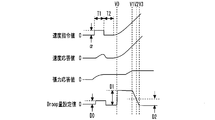
- FIG. 3 is a diagram showing speed command values, speed response values, tension response values, and Drop set values before and after starting the cold tandem rolling mill by the control device for the tandem rolling mill in the first embodiment.
- the speed command output unit 6a temporarily outputs the stepwise speed command value ⁇ to each of the plurality of stands 1. To do.
- the speed command output unit 6a temporarily outputs a speed command value of 1% of the set speed to each of the plurality of stands 1.
- the pair of work rolls 2 rotates in response to the speed command value.
- the rotation speed at this time is detected as a speed response value.
- the Drop amount setting unit 6b outputs the Drop amount setting value D0 to each of the plurality of stands 1. At this time, the Drop amount setting unit 6b reduces the Drop amount setting value D0 of the stand 1 in the subsequent stage. As a result, appropriate tension is applied to the rolled material 7 between the adjacent stands 1 in a state where the load of the play of the machines of the plurality of stands 1 is absorbed.
- the Drop amount setting unit 6b outputs the Drop amount setting value 0 in consideration of the fact that the starting friction torque is required due to the static friction of the bearing of the backup roll 3.
- the speed command output unit 6a When the time zone T2 has elapsed, the speed command output unit 6a outputs the speed command values for simultaneous activation for all of the plurality of stands 1.
- the speed PI successive control is performed in consideration of the fact that the static friction coefficient of the bearing of the backup roll 3 differs among the stands 1. Specifically, the difference between the tension response value of the rolled material between the adjacent stands 1 and the tension reference value is suppressed. For example, when the rolled material tends to be pulled, increasing the speed command value of the stand 1 causes the rolled material to loosen. For example, when the rolled material tends to be loose, the speed command value of the stand 1 is reduced so that the rolled material is pulled.
- the Drop amount setting unit 6b outputs the Drop amount setting value D1.
- D1 is set to a value larger than D0.
- the Drop amount setting unit 6b maintains the Drop amount setting value at D1 until the speed command value reaches the Drop amount maintaining speed V1.
- the Drop amount setting unit 6b gradually decreases the Drop amount setting value until the speed command value reaches the set minimum speed V3 via the rolling minimum speed V2. Specifically, when the speed command value is the minimum rolling speed V2, the Drop amount setting unit 6b outputs the Drop amount setting value D2. When the speed command value is the set minimum speed V3, the Drop amount setting unit 6b outputs the Drop amount setting value 0. As a result, in the low speed range, the imbalance of the speed due to the play of the machine between the plurality of stands 1 is suppressed, and the appropriate tension is maintained in the rolled material 7 between the adjacent stands 1.
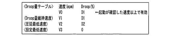
- FIG. 4 is a diagram showing a Drop amount table used by the Drop amount setting unit of the control device for the tandem rolling mill according to the first embodiment.
- the speed information and the Drop amount information are associated with each other.
- the information on the speed “V0” and the information on the Drop amount “D1” are associated with each other.
- the information on the speed “V1” and the information on the Drop amount “D1” are associated with each other.
- the information on the speed “V2” and the information on the Drop amount “D2” are associated with each other.
- the information on the speed “V3” and the information on the Drop amount “0” are associated with each other.
- the Drop amount setting unit 6b determines the Drop amount setting value based on the information in the Drop amount table. Specifically, the Drop amount setting unit 6b sets the Drop amount setting value to "D1" when the speed command value is between “V0" and “V1". The Drop amount setting unit 6b sets the Drop amount setting value to "D2" when the speed command value is “V2". The Drop amount setting unit 6b sets the Drop amount setting value to "0" when the speed command value is "V3".
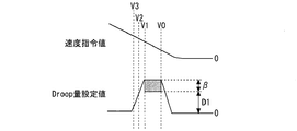
- FIG. 5 is a diagram showing a speed command value and a Drop set value when the cold tandem rolling mill is stopped by the control device of the tandem rolling mill in the first embodiment.
- the Drop amount setting unit 6b determines the Drop amount set value when the speed command value of the Drop amount table is between "V1" and "V0". A constant value ⁇ is added to “D1”. As a result, in the low speed region, the speed imbalance due to the rattling of the machines of the plurality of stands 1 is suppressed, and the appropriate tension is maintained in the rolled material 7 between the adjacent stands 1.
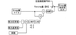
- FIG. 6 is a diagram showing a Drop gain circuit provided in the Drop amount setting unit of the control device for the tandem rolling mill according to the first embodiment.
- the Drop amount setting unit 6b determines the difference between the tension response value and the tension reference value. On the other hand, the coefficient is multiplied to obtain the gain.
- the Drop amount setting unit 6b sets the value obtained by multiplying the value obtained from the Drop amount table by the gain as the Drop amount setting value.
- the Drop amount set value becomes smaller than the value obtained from the Drop amount table.
- the tension response value between the adjacent stands 1 is larger than the tension reference value
- the Drop amount set value becomes larger than the value obtained from the Drop amount table.
- the Drop amount setting unit 6b causes the speed command output unit 6a to temporarily perform the speed command.
- the Drop amount setting value of the stand on the rear side is decreased.
- a Drop amount set value that is inversely proportional to the speed of the stand 1 on the rear side with respect to the speed of the stand 1 on the front side is used.
- appropriate tension is applied to the rolled material 7 between the adjacent stands 1 in a state where the play load of the machine of the plurality of stands 1 is absorbed. As a result, breakage of the rolled material 7 can be suppressed more reliably.
- the Drop amount setting unit 6b varies the Drop amount of the plurality of stands 1 according to the speed of the plurality of stands 1 after starting the cold tandem rolling mill, and immediately before stopping the cold tandem rolling mill.
- the constant value ⁇ is added to the Drop amount set value corresponding to the speed of.
- control as in the embodiment may be performed on the cold tandem rolling mill in which torque control is performed. Also in this case, breakage of the rolled material 7 can be suppressed more reliably.
- FIG. 7 is a hardware configuration diagram of the control device for the tandem rolling mill according to the first embodiment.
- Each function of the control device 6 can be realized by a processing circuit.
- the processing circuit comprises at least one processor 100a and at least one memory 100b.
- the processing circuitry comprises at least one dedicated hardware 200.
- each function of the control device 6 is realized by software, firmware, or a combination of software and firmware. At least one of software and firmware is described as a program. At least one of software and firmware is stored in at least one memory 100b. At least one processor 100a realizes each function of the control device 6 by reading and executing a program stored in at least one memory 100b.
- the at least one processor 100a is also called a central processing unit, a processing unit, an arithmetic unit, a microprocessor, a microcomputer, or a DSP.
- the at least one memory 100b is a non-volatile or volatile semiconductor memory such as a RAM, a ROM, a flash memory, an EPROM, an EEPROM, a magnetic disk, a flexible disk, an optical disk, a compact disk, a mini disk, a DVD, or the like.
- a non-volatile or volatile semiconductor memory such as a RAM, a ROM, a flash memory, an EPROM, an EEPROM, a magnetic disk, a flexible disk, an optical disk, a compact disk, a mini disk, a DVD, or the like.
- the processing circuit comprises at least one dedicated hardware 200
- the processing circuit may be implemented, for example, in a single circuit, a composite circuit, a programmed processor, a parallel programmed processor, an ASIC, an FPGA, or a combination thereof.
- each function of the control device 6 is realized by a processing circuit.
- each function of the control device 6 is collectively realized by a processing circuit.
- a part may be realized by the dedicated hardware 200 and the other part may be realized by software or firmware.
- the functions of the Drop amount setting unit 6b are realized by a processing circuit as the dedicated hardware 200, and the functions other than the functions of the Drop amount setting unit 6b are stored in at least one processor 100a in at least one memory 100b. It may be realized by reading and executing the program.
- the processing circuit realizes each function of the control device 6 with the hardware 200, software, firmware, or a combination thereof.
- control device for a tandem rolling mill can be used for a tandem rolling mill.
Landscapes
- Engineering & Computer Science (AREA)
- Mechanical Engineering (AREA)
- Health & Medical Sciences (AREA)
- Artificial Intelligence (AREA)
- Computer Vision & Pattern Recognition (AREA)
- Evolutionary Computation (AREA)
- Medical Informatics (AREA)
- Software Systems (AREA)
- Physics & Mathematics (AREA)
- General Physics & Mathematics (AREA)
- Automation & Control Theory (AREA)
- Control Of Metal Rolling (AREA)
- Control Of Multiple Motors (AREA)
Abstract
Description
図1は実施の形態1におけるタンデム圧延機の制御装置が適用される冷間タンデム圧延機の構成図である。
図2は実施の形態1におけるタンデム圧延機の制御装置のブロック図である。
図3は実施の形態1におけるタンデム圧延機の制御装置による冷間タンデム圧延機の起動前後の速度指令値と速度応答値と張力応答値とDroop設定値とを示す図である。
図4は実施の形態1におけるタンデム圧延機の制御装置のDroop量設定部が利用するDroop量テーブルを示す図である。
図5は実施の形態1におけるタンデム圧延機の制御装置による冷間タンデム圧延機の停止時の速度指令値とDroop設定値とを示す図である。
図6は実施の形態1におけるタンデム圧延機の制御装置のDroop量設定部に設けられたDroopゲイン回路を示す図である。
図7は実施の形態1におけるタンデム圧延機の制御装置のハードウェア構成図である。
Claims (8)
- 複数のスタンドが圧延材を挟み込んだ状態のタンデム圧延機の起動前に前記複数のスタンドに対する速度指令値を一時的に出力する速度指令出力部と、
前記速度指令出力部が一時的に速度指令値を出力している期間において、前記複数のスタンドに対し、より後段側のスタンドのDroop量設定値を小さくするDroop量設定部と、
を備えたタンデム圧延機の制御装置。 - 前記速度指令出力部は、前記タンデム圧延機の始動後に隣接したスタンドの間において圧延材の張力応答値と張力基準値との差が抑制されるように速度指令値を出力し、
前記Droop量設定部は、前記タンデム圧延機の始動後に前記複数のスタンドの速度に応じて前記複数のスタンドのDroop量設定値を変動させ、前記タンデム圧延機の停止直前に前記複数のスタンドの速度に応じたDroop量設定値に一定値を加算する請求項1に記載のタンデム圧延機の制御装置。 - 複数のスタンドが圧延材を挟み込んだ状態のタンデム圧延機の始動後に隣接したスタンドの間において圧延材の張力応答値と張力基準値との差が抑制されるように速度指令値を出力する速度指令出力部と、
前記タンデム圧延機の始動後に前記複数のスタンドの速度に応じて前記複数のスタンドのDroop量を変動させ、前記タンデム圧延機の停止直前に前記複数のスタンドの速度に応じたDroop量設定値に一定値を加算するDroop量設定部と、
を備えたタンデム圧延機の制御装置。 - 前記Droop量設定部は、前記タンデム圧延機の始動後において張力制御が始まるまで、前記複数のスタンドの各々の速度に応じて変動するDroop量のテーブルから得られた値に対し、隣接したスタンドの間において圧延材の張力応答値と張力基準値との差に応じたゲインを掛けた値をDroop量設定値とする請求項1から請求項3のいずれか一項に記載のタンデム圧延機の制御装置。
- 複数のスタンドが圧延材を挟み込んだ状態のタンデム圧延機の起動前に前記複数のスタンドに対するトルク指令値を一時的に出力するトルク指令出力部と、
前記トルク指令出力部が一時的にトルク指令値を出力している期間において、前記複数のスタンドに対し、より後段側のスタンドのDroop量設定値を小さくするDroop量設定部と、
を備えたタンデム圧延機の制御装置。 - 前記トルク指令出力部は、前記タンデム圧延機の始動後に隣接したスタンドの間において圧延材の張力応答値と張力基準値との差が抑制されるようにトルク指令値を出力し、
前記Droop量設定部は、前記タンデム圧延機の始動後に前記複数のスタンドのトルクに応じて前記複数のスタンドのDroop量設定値を変動させ、前記タンデム圧延機の停止直前に前記複数のスタンドのトルクに応じたDroop量設定値に一定値を加算する請求項5に記載のタンデム圧延機の制御装置。 - 複数のスタンドが圧延材を挟み込んだ状態のタンデム圧延機の始動後に隣接したスタンドの間において圧延材の張力応答値と張力基準値との差が抑制されるようにトルク指令値を出力するトルク指令出力部と、
前記タンデム圧延機の始動後に前記複数のスタンドのトルクに応じて前記複数のスタンドのDroop量を変動させ、前記タンデム圧延機の停止直前に前記複数のスタンドのトルクに応じたDroop量設定値に一定値を加算するDroop量設定部と、
を備えたタンデム圧延機の制御装置。 - 前記Droop量設定部は、前記タンデム圧延機の始動後において張力制御が始まるまで、前記複数のスタンドの各々のトルクに応じて変動するDroop量のテーブルから得られた値に対し、隣接したスタンドの間において圧延材の張力応答値と張力基準値との差に応じたゲインを掛けた値をDroop量設定値とする請求項5から請求項7のいずれか一項に記載のタンデム圧延機の制御装置。
Priority Applications (7)
| Application Number | Priority Date | Filing Date | Title |
|---|---|---|---|
| BR112020013281-0A BR112020013281B1 (pt) | 2018-12-12 | Aparelho de controle de laminador em tandem | |
| CN201880014149.1A CN111556797B (zh) | 2018-12-12 | 2018-12-12 | 连轧机的控制装置 |
| KR1020197024271A KR102232337B1 (ko) | 2018-12-12 | 2018-12-12 | 탠덤 압연기의 제어 장치 |
| US16/967,460 US20210220883A1 (en) | 2018-12-12 | 2018-12-12 | Control apparatus of tandem rolling mill |
| PCT/JP2018/045752 WO2020121454A1 (ja) | 2018-12-12 | 2018-12-12 | タンデム圧延機の制御装置 |
| JP2019536620A JP6806258B2 (ja) | 2018-12-12 | 2018-12-12 | タンデム圧延機の制御装置 |
| TW108105451A TWI716816B (zh) | 2018-12-12 | 2019-02-19 | 直列式壓延機的控制裝置 |
Applications Claiming Priority (1)
| Application Number | Priority Date | Filing Date | Title |
|---|---|---|---|
| PCT/JP2018/045752 WO2020121454A1 (ja) | 2018-12-12 | 2018-12-12 | タンデム圧延機の制御装置 |
Publications (1)
| Publication Number | Publication Date |
|---|---|
| WO2020121454A1 true WO2020121454A1 (ja) | 2020-06-18 |
Family
ID=71075756
Family Applications (1)
| Application Number | Title | Priority Date | Filing Date |
|---|---|---|---|
| PCT/JP2018/045752 Ceased WO2020121454A1 (ja) | 2018-12-12 | 2018-12-12 | タンデム圧延機の制御装置 |
Country Status (6)
| Country | Link |
|---|---|
| US (1) | US20210220883A1 (ja) |
| JP (1) | JP6806258B2 (ja) |
| KR (1) | KR102232337B1 (ja) |
| CN (1) | CN111556797B (ja) |
| TW (1) | TWI716816B (ja) |
| WO (1) | WO2020121454A1 (ja) |
Citations (2)
| Publication number | Priority date | Publication date | Assignee | Title |
|---|---|---|---|---|
| JPS603910A (ja) * | 1983-06-22 | 1985-01-10 | Nippon Steel Corp | タンデム圧延機の起動制御方法 |
| JPH0871624A (ja) * | 1994-09-06 | 1996-03-19 | Kawasaki Steel Corp | タンデム圧延機の速度制御方法 |
Family Cites Families (9)
| Publication number | Priority date | Publication date | Assignee | Title |
|---|---|---|---|---|
| JPS6160209A (ja) * | 1984-08-30 | 1986-03-27 | Kawasaki Steel Corp | タンデム圧延機における通板速度制御方式 |
| JP3041135B2 (ja) * | 1992-06-19 | 2000-05-15 | 株式会社東芝 | 連続熱間圧延機の制御装置 |
| JPH09285808A (ja) * | 1996-04-23 | 1997-11-04 | Kawasaki Steel Corp | タンデム圧延機の速度制御方法 |
| JP3426452B2 (ja) * | 1996-10-29 | 2003-07-14 | 新日本製鐵株式会社 | 冷間タンデム圧延機の稼働停止および再起動時の張力制御方法 |
| EP1287914B1 (en) * | 1997-12-12 | 2004-03-31 | Mitsubishi Heavy Industries, Ltd. | Rolling system and rolling method |
| JP5452968B2 (ja) * | 2009-04-10 | 2014-03-26 | 株式会社日立製作所 | 圧延装置およびその制御方法 |
| JP6173830B2 (ja) * | 2013-08-12 | 2017-08-02 | 株式会社日立製作所 | 圧延制御装置、圧延制御方法および圧延制御プログラム |
| JP5839053B2 (ja) * | 2014-01-06 | 2016-01-06 | 株式会社日立製作所 | 圧延装置およびその制御方法 |
| CN108213078B (zh) * | 2018-01-05 | 2019-07-12 | 武汉科技大学 | 冷轧平整机入口张力辊防积带的控制方法 |
-
2018
- 2018-12-12 WO PCT/JP2018/045752 patent/WO2020121454A1/ja not_active Ceased
- 2018-12-12 JP JP2019536620A patent/JP6806258B2/ja active Active
- 2018-12-12 KR KR1020197024271A patent/KR102232337B1/ko active Active
- 2018-12-12 CN CN201880014149.1A patent/CN111556797B/zh active Active
- 2018-12-12 US US16/967,460 patent/US20210220883A1/en not_active Abandoned
-
2019
- 2019-02-19 TW TW108105451A patent/TWI716816B/zh active
Patent Citations (2)
| Publication number | Priority date | Publication date | Assignee | Title |
|---|---|---|---|---|
| JPS603910A (ja) * | 1983-06-22 | 1985-01-10 | Nippon Steel Corp | タンデム圧延機の起動制御方法 |
| JPH0871624A (ja) * | 1994-09-06 | 1996-03-19 | Kawasaki Steel Corp | タンデム圧延機の速度制御方法 |
Also Published As
| Publication number | Publication date |
|---|---|
| BR112020013281A2 (pt) | 2021-06-22 |
| CN111556797B (zh) | 2022-03-25 |
| JP6806258B2 (ja) | 2021-01-06 |
| KR20200074052A (ko) | 2020-06-24 |
| TW202021682A (zh) | 2020-06-16 |
| TWI716816B (zh) | 2021-01-21 |
| US20210220883A1 (en) | 2021-07-22 |
| JPWO2020121454A1 (ja) | 2021-02-15 |
| CN111556797A (zh) | 2020-08-18 |
| KR102232337B1 (ko) | 2021-03-25 |
Similar Documents
| Publication | Publication Date | Title |
|---|---|---|
| JP5003492B2 (ja) | 圧延ロール用電動機の駆動装置 | |
| JP6806258B2 (ja) | タンデム圧延機の制御装置 | |
| CN101253006A (zh) | 轧辊用电动机的驱动装置 | |
| JP7222790B2 (ja) | 圧延制御装置、圧延制御方法および圧延機 | |
| JP5737019B2 (ja) | 冷間タンデム圧延機の制御装置 | |
| JP3426452B2 (ja) | 冷間タンデム圧延機の稼働停止および再起動時の張力制御方法 | |
| CN104428075B (zh) | 处理在轧机中的轧件的方法 | |
| JP5383239B2 (ja) | 圧延機での振動防止方法 | |
| JPH025483B2 (ja) | ||
| JPH09285808A (ja) | タンデム圧延機の速度制御方法 | |
| JPH1045331A (ja) | 繊維機械における張力制御装置 | |
| US12569898B2 (en) | Tail end buckling suppression device | |
| JPS5949796B2 (ja) | 圧延機起動補償装置 | |
| JP2024166081A (ja) | 圧延機の板厚制御方法および圧延機の板厚制御装置ならびに圧延機の板厚制御方法を用いる鋼板の製造方法 | |
| JPH0970617A (ja) | 巻戻機の張力制御方式 | |
| JP3903376B2 (ja) | ブライドルロール制御装置 | |
| JP2588912Y2 (ja) | 静止張力制御回路 | |
| JP2025132378A (ja) | ヘルパーロールの制御システム | |
| JPS603910A (ja) | タンデム圧延機の起動制御方法 | |
| JP3364086B2 (ja) | 圧延材の張力制御装置 | |
| JPS5863089A (ja) | タンデム圧延機の電動機速度制御装置 | |
| JP2016078973A (ja) | 張力制御装置および張力制御方法 | |
| JPS5822405A (ja) | バツクラツシユのある駆動系における軸振動防止方法 | |
| JPH07324295A (ja) | 抄紙機用電動機制御装置 | |
| JPS5945012A (ja) | タンデム圧延機の速度垂下率制御方法 |
Legal Events
| Date | Code | Title | Description |
|---|---|---|---|
| ENP | Entry into the national phase |
Ref document number: 2019536620 Country of ref document: JP Kind code of ref document: A |
|
| 121 | Ep: the epo has been informed by wipo that ep was designated in this application |
Ref document number: 18942777 Country of ref document: EP Kind code of ref document: A1 |
|
| REG | Reference to national code |
Ref country code: BR Ref legal event code: B01A Ref document number: 112020013281 Country of ref document: BR |
|
| NENP | Non-entry into the national phase |
Ref country code: DE |
|
| ENP | Entry into the national phase |
Ref document number: 112020013281 Country of ref document: BR Kind code of ref document: A2 Effective date: 20200629 |
|
| 122 | Ep: pct application non-entry in european phase |
Ref document number: 18942777 Country of ref document: EP Kind code of ref document: A1 |