WO2020121434A1 - 配線部材及び荷姿形態の配線部材 - Google Patents
配線部材及び荷姿形態の配線部材 Download PDFInfo
- Publication number
- WO2020121434A1 WO2020121434A1 PCT/JP2018/045662 JP2018045662W WO2020121434A1 WO 2020121434 A1 WO2020121434 A1 WO 2020121434A1 JP 2018045662 W JP2018045662 W JP 2018045662W WO 2020121434 A1 WO2020121434 A1 WO 2020121434A1
- Authority
- WO
- WIPO (PCT)
- Prior art keywords
- sheet
- shaped
- linear transmission
- shaped member
- electric wire
- Prior art date
- Legal status (The legal status is an assumption and is not a legal conclusion. Google has not performed a legal analysis and makes no representation as to the accuracy of the status listed.)
- Ceased
Links
Images



Classifications
-
- H—ELECTRICITY
- H01—ELECTRIC ELEMENTS
- H01B—CABLES; CONDUCTORS; INSULATORS; SELECTION OF MATERIALS FOR THEIR CONDUCTIVE, INSULATING OR DIELECTRIC PROPERTIES
- H01B7/00—Insulated conductors or cables characterised by their form
-
- H—ELECTRICITY
- H02—GENERATION; CONVERSION OR DISTRIBUTION OF ELECTRIC POWER
- H02G—INSTALLATION OF ELECTRIC CABLES OR LINES, OR OF COMBINED OPTICAL AND ELECTRIC CABLES OR LINES
- H02G3/00—Installations of electric cables or lines or protective tubing therefor in or on buildings, equivalent structures or vehicles
- H02G3/30—Installations of cables or lines on walls, floors or ceilings
-
- B—PERFORMING OPERATIONS; TRANSPORTING
- B60—VEHICLES IN GENERAL
- B60R—VEHICLES, VEHICLE FITTINGS, OR VEHICLE PARTS, NOT OTHERWISE PROVIDED FOR
- B60R16/00—Electric or fluid circuits specially adapted for vehicles and not otherwise provided for; Arrangement of elements of electric or fluid circuits specially adapted for vehicles and not otherwise provided for
- B60R16/02—Electric or fluid circuits specially adapted for vehicles and not otherwise provided for; Arrangement of elements of electric or fluid circuits specially adapted for vehicles and not otherwise provided for electric constitutive elements
- B60R16/0207—Wire harnesses
-
- B—PERFORMING OPERATIONS; TRANSPORTING
- B60—VEHICLES IN GENERAL
- B60R—VEHICLES, VEHICLE FITTINGS, OR VEHICLE PARTS, NOT OTHERWISE PROVIDED FOR
- B60R16/00—Electric or fluid circuits specially adapted for vehicles and not otherwise provided for; Arrangement of elements of electric or fluid circuits specially adapted for vehicles and not otherwise provided for
- B60R16/02—Electric or fluid circuits specially adapted for vehicles and not otherwise provided for; Arrangement of elements of electric or fluid circuits specially adapted for vehicles and not otherwise provided for electric constitutive elements
- B60R16/0207—Wire harnesses
- B60R16/0215—Protecting, fastening and routing means therefor
-
- H—ELECTRICITY
- H01—ELECTRIC ELEMENTS
- H01B—CABLES; CONDUCTORS; INSULATORS; SELECTION OF MATERIALS FOR THEIR CONDUCTIVE, INSULATING OR DIELECTRIC PROPERTIES
- H01B13/00—Apparatus or processes specially adapted for manufacturing conductors or cables
- H01B13/012—Apparatus or processes specially adapted for manufacturing conductors or cables for manufacturing wire harnesses
- H01B13/01209—Details
-
- H—ELECTRICITY
- H02—GENERATION; CONVERSION OR DISTRIBUTION OF ELECTRIC POWER
- H02G—INSTALLATION OF ELECTRIC CABLES OR LINES, OR OF COMBINED OPTICAL AND ELECTRIC CABLES OR LINES
- H02G3/00—Installations of electric cables or lines or protective tubing therefor in or on buildings, equivalent structures or vehicles
- H02G3/02—Details
-
- H—ELECTRICITY
- H01—ELECTRIC ELEMENTS
- H01B—CABLES; CONDUCTORS; INSULATORS; SELECTION OF MATERIALS FOR THEIR CONDUCTIVE, INSULATING OR DIELECTRIC PROPERTIES
- H01B13/00—Apparatus or processes specially adapted for manufacturing conductors or cables
- H01B13/012—Apparatus or processes specially adapted for manufacturing conductors or cables for manufacturing wire harnesses
Definitions
- This invention relates to wiring members.
- Patent Document 1 includes a functional exterior member formed in a sheet shape, and an electric wire arranged so as to overlap the functional exterior member in at least a partial region along the longitudinal direction. Disclosed is a wire harness in which at least a part of an overlapping portion of an insulating coating and the functional exterior member is welded.
- the wire harness disclosed in Patent Document 1 can be made into a compact form by bending a sheet-shaped functional exterior member during packaging, transportation, or the like.
- the electric wire route may be disturbed or peeled off on the functional exterior member.
- one of the electric wires straddles another electric wire on the sheet-shaped functional exterior member according to the electric wire path, the connection destination position to the connector, and the like. In some cases, they may be arranged to intersect. At the intersection of the electric wires, the holding force of the electric wire straddling another electric wire may be weakened. Therefore, when the functional exterior member is bent at the intersection of the electric wires, the electric wire path in the functional exterior member may be disturbed or peeled off.
- an object of the present invention is to prevent the path of the linear transmission member from being disturbed on the sheet-shaped member and prevent the linear transmission member from being separated from the sheet-shaped member.
- a wiring member includes a sheet-shaped member and a plurality of linear transmission members fixed on the sheet-shaped member.
- the plurality of linear transmission members are fixed on the sheet-shaped member such that a part of them intersects with the other linear transmission member, and intersections of the plurality of linear transmission members are folded. It is located so as to avoid bending marks.
- a second aspect is the wiring member according to the first aspect, further comprising a vehicle fixing portion attached to the sheet-shaped member, wherein an intersection of the plurality of linear transmission members is the sheet-shaped member. Of these, those located in a region corresponding to the vehicle fixing portion are included.
- a third aspect is the wiring member according to the first or second aspect, wherein an intersection of the plurality of linear transmission members is between an extension direction central portion and an end portion of the sheet-shaped member. Including those located near the edges.
- a fourth aspect is a wiring member according to any one of the first to third aspects, in which a rigidity imparting member that imparts rigidity is provided at the intersection.
- a wiring member in a packaging form includes a sheet-shaped member and a plurality of linear transmission members fixed on the sheet-shaped member, and is one of the plurality of linear transmission members.
- the plurality of linear transmission members are fixed on the sheet-shaped member, and the sheet-shaped member and the plurality of linear transmission members are bent so that a portion intersects with the other linear transmission member. And the intersection of the plurality of linear transmission members is located so as to avoid the bent portion.
- the sheet-shaped member is not This means that the linear transmission member was bent so as to avoid the intersection. Therefore, the path of the linear transmission member is disturbed on the sheet-shaped member and the linear transmission member is prevented from being separated from the sheet-shaped member.
- the sheet-shaped member is bent at a position that avoids the vehicle fixing part. Therefore, according to the second aspect, the wiring member is not bent at the intersection, the path of the linear transmission member is disturbed on the sheet-shaped member, or the linear transmission member is separated from the sheet-shaped member. Is suppressed.
- the intersection of the plurality of linear transmission members is located closer to the end portion between the central portion and the end portion in the extending direction of the sheet-shaped member, It is less likely that the intersection of the plurality of linear transmission members will be bent, the path of the linear transmission member is disturbed on the sheet-shaped member, or the linear transmission member is separated from the sheet-shaped member. Suppressed.
- the rigidity imparting member that imparts rigidity is provided at the intersection, it is difficult to bend at the intersection. Therefore, the path of the linear transmission member is disturbed on the sheet-shaped member and the linear transmission member is prevented from being separated from the sheet-shaped member.
- the intersection of the plurality of linear transmission members is located avoiding the bent portion of the sheet-shaped member, the route of the linear transmission member is disturbed on the sheet-shaped member. The separation of the linear transmission member from the sheet-shaped member is suppressed.
- FIG. 1 is a schematic plan view showing the wiring member 10
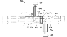
- FIG. 2 is a schematic plan view showing the wiring member 10 in a folded state, that is, a wiring member 10B in a packing form.
- the wiring member 10 includes a sheet-shaped member 20 and a plurality of linear transmission members 30.
- the wiring member 10 also includes connectors 40A, 40B, 40C, 40D.
- the linear transmission member 30 is a linear member that transmits electricity or light.
- the sheet-shaped member 20 is a sheet-shaped member.
- a plurality of linear transmission members 30 are fixed on the sheet-shaped member 20.
- the sheet-shaped member 20 is fixed so that a part of the plurality of linear transmission members 30 intersects with the other linear transmission members 30.
- Bending marks 12 and 13 are formed on the wiring member 10. That is, when the wiring member 10 is packed, transported, or the like, the wiring member 10 is bent into a compact packing form.
- the folding traces 12 and 13 are the traces that are bent when the packaging form is formed.
- the wiring member 10 may be bent so that a part of the wiring member 10 can be overlapped with another portion.
- the folding marks 12 and 13 are assumed to remain in the sheet-like member 20 as a crease, or to remain in the linear transmission member 30 as a crease.
- the plurality of linear transmission members 30 intersect on the sheet-shaped member 20, and the intersections 38a, 38b, 38c, 38d, 39 are located avoiding the folds 12, 13.
- the connectors 40A, 40B, 40C, 40D are parts connected to the parts mounted on the vehicle.
- the ends of the plurality of linear transmission members 30 are connected to any of the connectors 40A, 40B, 40C, 40D.
- the wiring member 10 With the wiring member 10 mounted on the vehicle, a plurality of connectors 40A, 40B, 40C, 40D are connected to the components mounted on the vehicle. As a result, electric signals are transmitted/received, electric power is transmitted/received, and optical signals are transmitted/received between the parts mounted on the vehicle. That is, the wiring member 10 is a wiring component that connects components mounted on the vehicle. In particular, in the wiring member 10, since the plurality of linear transmission members 30 are branched, it is possible to connect the plurality of components via the branched paths.
- the linear transmission member 30 may be a linear member that transmits electricity or light.
- the linear transmission member may be a general electric wire having a core wire and a coating around the core wire, or may be a bare conductor wire, a shield wire, an enamel wire, a nichrome wire, an optical fiber, or the like.
- the linear transmission member for transmitting electricity various signal lines and various power lines may be used.
- the linear transmission member that transmits electricity may be used as an antenna, a coil, or the like that sends or receives a signal or power to or from a space.
- the linear transmission member 30 is the general electric wire 30 (hereinafter simply referred to as the electric wire 30).
- the electric wire 30 has a core wire as a transmission line body and an insulating coating as a coating for covering the core wire.
- Each description regarding the electric wire is applicable to each example of the linear transmission member except for the configuration that is not applicable.
- the core wire is composed of one or more strands.
- the element wire is formed of a conductor such as copper, a copper alloy, aluminum, or an aluminum alloy.
- the core wire is composed of a plurality of strands, the plurality of strands may be twisted.
- the insulating coating is formed by extruding a resin material such as PVC (polyvinyl chloride) or PE (polyethylene) around the core wire.
- the electric wire 30 is a so-called round electric wire having a circular cross section.
- the sheet-shaped member 20 is a flexible sheet-shaped member that can hold the electric wire 30 in a two-dimensionally positioned state and can be bent.
- the material forming the sheet-shaped member 20 is not particularly limited, but the sheet-shaped member 20 is preferably made of a material containing a resin such as PVC (polyvinyl chloride), PET (polyethylene terephthalate), or PP (polypropylene). It is formed.
- the sheet-shaped member 20 may be a sheet member whose inside is uniformly filled, or may be a non-woven sheet or the like.
- the sheet-shaped member 20 may include a material such as a metal.
- the sheet-shaped member 20 may be a single layer or a plurality of laminated layers. When a plurality of layers are laminated, for example, a resin layer and a resin layer may be laminated. Further, for example, it is conceivable that the resin layer and the metal layer are laminated.
- An electric wire 30 is fixed on one main surface of the sheet-shaped member 20. On one main surface of the sheet-shaped member 20, the electric wire 30 is fixed along a fixed path.
- a plurality of electric wires 30 are fixed on one main surface of the sheet-shaped member 20.
- the path of the electric wire 30 on the sheet-shaped member 20 may be a straight line or may be a path that bends in the middle.
- the plurality of electric wires 30 are branched in the middle.
- the sheet-shaped member 20 includes a first sheet-shaped portion 22 and second sheet-shaped portions 24a and 24b.
- the second sheet-shaped portions 24 a and 24 b are bent at the intermediate portion in the extending direction of the first sheet-shaped portion 22 and branched to the side of the first sheet-shaped portion 22.
- the first sheet-shaped portion 22 is formed in a strip shape that is elongated and extends straight.
- the first sheet-shaped portion may be curved.
- the second sheet-shaped portions 24a, 24b are formed in a strip shape that is elongated and extends straight.
- the second sheet-shaped portion 24 a is branched so as to extend outward from one side portion of the first sheet-shaped portion 22 toward one side of the first sheet-shaped portion 22.
- the second sheet-shaped portion 24b is branched so as to extend outward from the other side portion of the first sheet-shaped portion 22 toward the other side of the first sheet-shaped portion 22.
- the second sheet-shaped portions 24a and 24b are provided at different positions in the extending direction of the first sheet-shaped portion 22.
- the second sheet-shaped portion 24 a is provided near one end of the first sheet-shaped portion 22, and the second sheet-shaped portion 24 b is provided near the other end of the first sheet-shaped portion 22.
- two of the second sheet-shaped portions may be provided at the same position in the extending direction of the first sheet-shaped portion.
- the second sheet-shaped portions 24 a and 24 b extend in a posture orthogonal to the extending direction of the first sheet-shaped portion 22.
- the second sheet-shaped portion may extend obliquely with respect to the extending direction of the first sheet-shaped portion.
- the number of the second sheet-shaped portions may be one, or may be three or more.
- the plurality of electric wires 30 are distinguished from the electric wires 30a, 30b, 30c, 30d, 30e, 30f.
- the plurality of electric wires 30a, 30b, 30c, 30d, 30e, 30f are fixed to the first sheet-shaped portion 22 in parallel at one end side of the first sheet-shaped portion 22.
- the plurality of electric wires 30a, 30b, 30c, 30d, 30e, 30f are connected to the connector 40A at one end of the first sheet-shaped portion 22.
- the connector 40A has a configuration in which terminals are housed in a housing in a predetermined arrangement order.
- the arrangement of the plurality of electric wires 30a, 30b, 30c, 30d, 30e, 30f is determined according to how the terminals connected to the plurality of electric wires 30a, 30b, 30c, 30d, 30e, 30f are housed in the housing. ..
- the connector 40A may be fixed to the sheet-shaped member 20.
- the ends of the electric wires 30a, 30b, 30c, 30d, 30e, 30f may extend from the sheet-shaped member 20 and be connected to the connector 40A.
- a part of the electric wire 30f is bent midway between the one end portion of the first sheet-shaped portion 22 and the second sheet-shaped portion 24a, and the other electric wires 30a and 30b. , 30c, 30d, 30e in an oblique posture.
- the location where the electric wire 30f intersects the electric wires 30a, 30b, 30c, 30d, and 30e is an example of the intersection location 38a. Since the electric wire 30f intersects the electric wires 30a, 30b, 30c, 30d, and 30e in an oblique posture, the electric wire 30f can be bent at a gentle angle.
- the electric wire 30f is arranged in parallel with the other electric wires 30a, 30b, 30c, 30d, and 30e from the intersection point 38a toward the other end of the first sheet-shaped portion 22, and is located at the intermediate portion in the extending direction of the first sheet-shaped portion 22. Fixed.
- the electric wire 30f is bent toward one side of the first sheet-shaped portion 22 at the location where the second sheet-shaped portion 24a is provided, and branches off with respect to the other electric wires 30a, 30b, 30c, 30e. It extends toward the sheet-shaped portion 24a.
- the other part of the electric wire 30d is a portion where the second sheet-shaped portion 24a is provided, is bent from the original part on the way, and is branched to the other electric wires 30a, 30b, 30c, and 30e. It extends toward the portion 24a.
- some of the electric wires 30d and 30f branch off from the other electric wires 30a, 30b, 30c, and 30e and extend in a posture orthogonal to them, and the second sheet-shaped portion 24a. Fixed in parallel on top.
- the location where the electric wire 30d intersects with the other electrical wires 30a, 30b, 30c is an example of the crossing location 38b.
- the intersections 38a and 38b are an example of locations where a part of the plurality of linear transmission members intersects with another linear transmission member so as to branch.
- the electric wires 30d and 30f are connected to the connector 40B at the ends of the second sheet-shaped portion 24a.
- the arrangement order of the electric wires 30d and 30f is also determined according to the arrangement in which the terminals connected to the ends of the electric wires 30d and 30f are housed in the connector 40B.
- Some of the electric wires 30a and 30b are branched and extend in a posture orthogonal to the other electric wires 30c and 30e.
- the bending radii of the electric wires 30a, 30b may be approximately the same as the distance between the electric wires 30a, 30b, 30c, 30d, 30e, 30f, may be smaller than the distance, or may be larger than the distance. ..
- intersection of the electric wire 30a with the other electric wires 30c and 30e is the intersection 38c.
- a portion where the electric wire 30b intersects with the other electric wires 30c and 30e is an intersection portion 38d.
- the intersections 38c and 38d are an example of locations where some of the plurality of linear transmission members intersect so as to branch to other linear transmission members.
- the electric wires 30a and 30c branch on the first sheet-shaped portion 22 with respect to the other electric wires 30c and 30e, extend toward the second sheet-shaped portion 24b, and are arranged in parallel on the second sheet-shaped portion 24b. Fixed.
- the electric wires 30a and 30b are connected to the connector 40C at the ends of the second sheet-shaped portion 24b.
- the arrangement order of the electric wires 30a and 30b is also determined according to the arrangement in which the terminals connected to the ends of the electric wires 30a and 30b are accommodated in the connector 40C.
- the remaining electric wires 30c and 30e extend toward the other end of the first sheet-shaped portion 22.
- the arrangement order of the electric wires 30c and 30e at the other end of the first sheet-shaped portion 22 is determined according to the arrangement in which the terminals connected to the ends of the electric wires 30a and 30b are accommodated in the connector 40D.
- the arrangement order of the electric wires 30c and 30e at the other end of the first sheet-shaped portion 22 and the electric wires 30c and 30e at the one end of the first sheet-shaped portion 22 are arranged.
- the order of arrangement is different.
- the electric wire 30e is bent midway so as to intersect the electric wire 30c so as to change the arrangement order of the plurality of electric wires 30c and 30e.
- the electric wire 30e is bent so as to intersect the electric wire 30c at an intermediate portion between the intersections 38c and 38d and the other end of the first sheet-like portion 22, and the other end of the first sheet-like portion 22 is bent. It extends parallel to the electric wire 30c at a position closer to it.
- the electric wire 30e intersects the electric wire 30c in an oblique posture, and portions of the electric wire 30e on both sides intersecting the electric wire 30c extend in a parallel posture with respect to the electric wire 30c.
- a portion of the electric wire 30e that intersects the electric wire 30c and a portion that extends parallel to the electric wire 30c are curved in a curved line. This bending radius may be similar to the distance between the electric wires 30a, 30b, 30c, 30d, 30e, and 30f, may be smaller than the distance, or may be larger than the distance, as described above. Good.
- a crossing point 39 between the electric wire 30c and the electric wire 30e is an example of a crossing point between the electric wire 30c and the electric wire 30e so that the arrangement order of the electric wires 30c and 30e is changed.
- the electric wires 30c and 30e are fixed in parallel on the other end of the first sheet-shaped portion 22.
- the electric wires 30c and 30e are connected to the connector 40D at the other end of the first sheet-shaped portion 22.
- Fold marks 12, 13 are formed on the wiring member 10.
- the folds 12 and 13 are folds of the wiring member 10 in order to have a compact packing form for the purpose of packing, transporting, or the like.
- the wiring member 10 is bent at two locations in the extending direction of the first sheet-shaped portion 22.
- Each bending line (the line that becomes the bending marks 12 and 13 when folded and then expanded) is orthogonal to the extending direction of the first sheet-shaped portion 22.
- One fold line (corresponding to the fold mark 12) is located between one end of the first sheet-shaped portion 22 and the second sheet-shaped portion 24a.
- the other bending line (corresponding to the bending mark 13) is located between the other end of the first sheet-shaped portion 22 and the second sheet-shaped portion 24b and closer to the second sheet-shaped portion 24b.
- the method of bending the wiring member 10 is not limited to the above example, but the wiring member 10 may be bent at one place, or may be bent at three or more places.
- the wiring member 10 may be bent at a line oblique to the extending direction of the first sheet-shaped portion 22.
- intersections 38a, 38b, 38c, 38d, 39 are located avoiding the fold marks 12, 13. More specifically, the intersection portion 38a is located closer to one end of the first sheet-shaped portion 22 than the folding mark 12 in the first sheet-shaped portion 22. The intersections 38b, 38c, 38d are located between the folds 12 and 13 in the first sheet-shaped portion 22. The intersection 39 is located closer to the other end of the first sheet-shaped portion 22 than the fold 13 in the first sheet-shaped portion 22.
- intersections 38a and 39 may be located near the ends between the central portion M of the sheet-shaped member 20 in the extending direction and the ends.
- the longest first sheet-shaped portion 22 of the sheet-shaped member 20 is used as a reference, and the central portion in the extending direction is M.
- the intersection 39 is located between the central portion M and the other end T of the first sheet-like portion 22 and at a position near the other end T. Since the purpose of folding the sheet-shaped member 20 is to make the sheet-shaped member 20 as compact as possible, even if the sheet-shaped member 20 is folded at the end, the effect on the request for compactness is small. For this reason, the sheet-shaped member 20 is rarely bent at the end. Therefore, by providing the intersection 39 at a position closer to the end T, bending of the intersection 39 is suppressed.
- the mode of fixing the electric wire 30 and the sheet-like member 20 may be fixing at the contact portion, fixing at the non-contact portion, or both may be used together.
- the contact portion fixing means that the portions where the electric wire 30 and the sheet-like member 20 are in contact with each other are fixed to each other.
- the non-contact part fixing is a fixing mode other than the contact part fixing. For example, a sewing thread, another sheet member, an adhesive tape, or the like presses the electric wire 30 toward the sheet member 20, and a sewing thread, another sheet member, an adhesive tape, or the like surrounds the electric wire 30 and the sheet member 20.
- the electric wire 30 and the sheet-shaped member 20 are sandwiched, and the electric wire 30 and the sheet-shaped member 20 are maintained in a fixed state.
- the electric wire 30 and the sheet-shaped member 20 are in a state of being fixed at the contact portion.
- the respective descriptions regarding the fixing of the contact portion can be applied to the fixing of the non-contact portion as long as the configuration is not applicable.
- the contact portion may be indirectly fixed, the contact portion may be directly fixed, or both may be used together in different areas.
- the contact portion indirect fixing means that the electric wire 30 and the sheet-shaped member 20 are indirectly fixed to each other through an intervening member such as an adhesive, a pressure-sensitive adhesive, or a double-sided pressure-sensitive adhesive tape provided therebetween.
- the direct fixing of the contact portion means that the electric wire 30 and the sheet-shaped member 20 are directly fixed to each other without an adhesive or the like provided separately.
- the direct fixing of the contact portion it is conceivable that the resin contained in at least one of the electric wire 30 and the sheet-shaped member 20 is melted and fixed to the contact portion. Below, it demonstrates as what the electric wire 30 and the sheet-shaped member 20 are in the state of a contact site direct fixation. The respective descriptions regarding the direct fixing of the contact portion can be applied to the indirect fixing of the contact portion as long as the configuration is not applicable.
- the resin When the state of directly fixing the contact portion is formed, the resin may be melted by heat or may be melted by a solvent, for example. That is, the state of directly fixing the contact portion may be a state of directly fixing the contact portion by heat or a state of directly fixing the contact portion by a solvent. It is preferable that the contact portion is directly fixed by heat.
- the structure for directly fixing the contact portion is not particularly limited, and various structures including known structures such as welding, fusion, and welding can be used.
- various welding configurations such as ultrasonic welding, heating/pressurizing welding, hot air welding, and high frequency welding can be adopted.
- the contact portion directly fixed state is formed by these configurations, the electric wire 30 and the sheet-shaped member 20 are brought into the contact portion directly fixed state by the configuration.
- the state where the contact portion is directly fixed is formed by ultrasonic welding
- the electric wire 30 and the sheet-shaped member 20 are brought into the state where the contact portion is directly fixed by ultrasonic welding.
- the portion where the contact portion is directly fixed by heat by welding (the portion where the electric wire 30 and the sheet-like member 20 are fixed) is a welded portion, and among these, the fixed portion by ultrasonic welding is an ultrasonic welded portion, and heat pressure welding.
- the fixed portion by means of may be referred to as a heating and pressure welding portion or the like.
- both the resin contained in the coating of the electric wire 30 and the resin contained in the sheet-shaped member 20 may be melted. In this case, both resins may be mixed and a clear interface may not be formed.
- both resins may be mixed with each other and a clear interface may not be formed.
- the intersections 38a, 38b, 38c, 38d, 39 of the plurality of electric wires 30 are positioned so as to avoid the bending parts 12A, 13A. It is in a state where it has been made (see FIG. 2).
- the intersections 38a, 38b, 38c, 38d, 39 of the plurality of electric wires 30 are positioned avoiding the folds 12, 13 which are the folds 12A, 13A. (See FIG. 1).
- the folding marks 12 and 13 are observed as marks left on the sheet-shaped member 20 as creases or marks left on the electric wire 30 as creases.
- the intersections 38a, 38b, 38c, 38d, 39 of the plurality of electric wires 30 are positioned so as to avoid the bending portions 12A, 13A of the sheet-shaped member 20. Therefore, the path of the electric wire 30 is disturbed on the sheet-shaped member 20 and the electric wire 30 is prevented from being separated from the sheet-shaped member 20. Further, in the wiring member 10 as well, since the intersections 38a, 38b, 38c, 38d, 39 of the plurality of electric wires 30 are located avoiding the folding marks 12, 13 of the sheet-like member 20, packaging and transportation are performed.
- the sheet-shaped member 20 is bent so as to avoid the intersections 38a, 38b, 38c, 38d, 39 of the plurality of electric wires 30. Therefore, the path of the electric wire 30 is disturbed on the sheet-shaped member 20 and the electric wire 30 is prevented from being separated from the sheet-shaped member 20.
- the reason why the wiring member 10 is folded at the time of packaging, transportation, etc. is to achieve compactness, so there is little possibility of bending the wiring member 10 at a position near the end of the sheet-shaped member 20. Therefore, the intersections 38a, 39 of the electric wires 30 are located closer to the end T between the central portion M and the end T of the sheet-shaped member 20 in the extending direction, so that the intersections of the plurality of electric wires 30 are formed. The possibility that the wires 38a, 39 are bent is reduced, and the path of the electric wire 30 on the sheet-shaped member 20 is disturbed and the electric wire 30 is prevented from being separated from the sheet-shaped member 20.
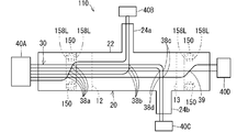
- FIG. 3 is a schematic plan view showing the wiring member 110 according to the first modification.
- the wiring member 110 further includes a vehicle fixing portion 150 attached to the sheet-shaped member 20.
- the vehicle fixing portion 150 is a component that can be fixed to the vehicle.
- vehicle fixing portion 150 for example, a component that can be fitted into a hole formed in the vehicle and locked and fixed, that is, a so-called clamp or clip can be used.
- fixing structure of the vehicle fixing portion 150 to the sheet-like member 20 various fixing structures such as ultrasonic welding, heat welding, fixing using an adhesive or a pressure sensitive adhesive, and pinching fixing can be adopted.
- the vehicle fixing portion 150 is fixed to a part of the first sheet-shaped portion 22 of the sheet-shaped member 20 in the extending direction. Here, it is provided between one end of the first sheet-shaped portion 22 and the bend mark 12.
- the vehicle fixing portions 150 are provided on both sides of the first sheet-shaped portion 22.
- the vehicle fixing portion 150 may be provided only on one side of the first sheet-shaped portion 22, or may be provided at a widthwise intermediate portion of the first sheet-shaped portion 22.
- intersection 38a is located in a region of the sheet-shaped member 20 corresponding to the vehicle fixing portion 150.
- both ends of the vehicle fixing portion 150 in the extending direction of the first sheet-shaped portion 22 intersect inside the pair of lines 158L extending in the direction orthogonal to the extending direction of the first sheet-shaped portion 22.
- Location 38a is located.
- the vehicle fixing portion 150 is also provided between the other end of the first sheet-shaped portion 22 and the bending mark 13.
- the intersection 39 is located in a region of the sheet-shaped member 20 corresponding to the vehicle fixing portion 150.
- the vehicle fixing portion 150 is a component formed of resin, metal, or the like, and the first sheet-shaped portion 22 is difficult to bend in the region where the vehicle fixing portion 150 is provided. Therefore, the sheet-shaped member 20 is bent at a position avoiding the vehicle fixing portion 150. Therefore, at the intersections 38a and 39, the wiring member 110 is not bent, and the path of the electric wire 30 is disturbed on the sheet-shaped member 20 and the electric wire 30 is prevented from being separated from the sheet-shaped member 20. ..
- FIG. 4 is a schematic plan view showing a wiring member 210 according to the second modification.
- the wiring member 210 is provided with rigidity imparting members 250A, 250B, 250C, 250D that impart rigidity to the intersections 38a, 38b, 38c, 38d, 39.
- the rigidity imparting members 250A, 250B, 250C, and 250D are formed in a sheet shape, and are fixed to the sheet-shaped member 20 so as to cover the electric wire 30 from the side where the electric wire 30 is fixed with respect to the sheet-shaped member 20. There is.
- the rigidity imparting member 250A covers the entire widthwise region of the first sheet-shaped portion 22 including the intersection 38a so as to impart rigidity to the intersection 38a.
- the rigidity imparting member 250B covers the entire widthwise region of the first sheet-shaped portion 22 including the intersection 38b so as to impart rigidity to the intersection 38b.
- the rigidity imparting member 250C covers the entire widthwise region of the first sheet-shaped portion 22 including the intersections 38c and 38d so as to impart rigidity to the intersections 38c and 38d.
- the rigidity imparting member 250D covers the entire region in the width direction of the first sheet-shaped portion 22 including the intersection 39 so as to impart rigidity to the intersection 39.
- the rigidity imparting members 250A, 250B, 250C, and 250D do not need to cover the entire width direction of the first sheet-shaped portion 22, but may cover at least the intersections 38a, 38b, 38c, 38d, and 39. Further, the rigidity imparting members 250A, 250B, 250C and 250D do not have to be provided for all the intersections 38a, 38b, 38c, 38d and 39.
- a rigidity imparting member may be provided at a part of the intersections 38a, 38b, 38c, 38d, 39.
- the rigidity imparting members 250A, 250B, 250C, 250D may be provided in a wider area with respect to the sheet member 20.
- the rigidity-imparting member may be provided in the entire area of the first sheet-shaped portion 22 that avoids the linear areas that are the bending marks 12 and 13.
- the rigidity imparting members 250A, 250A, 250B, 250C, 250D may be, for example, resin sheets of PVC, PE, PET, PP, PA, etc., or metal sheets of aluminum, copper, etc.
- the rigidity imparting members 250A, 250A, 250B, 250C, 250D may be fiber materials such as woven fabric, knitted fabric, and non-woven fabric, or may be molded materials such as members formed by extrusion molding or injection molding.
- the rigidity imparting members 250A, 250A, 250B, 250C, and 250D may be foam-molded foam materials, or may be solid materials that are not foam-molded and are uniformly solid.
- the rigidity imparting members 250A, 250A, 250B, 250C and 250D may have only one layer or may have a plurality of layers.
- the rigidity-imparting members 250A, 250A, 250B, 250C, and 250D may be fixed to the sheet-shaped member 20 by any configuration.
- the rigidity imparting members 250A, 250A, 250B, 250C, and 250D may be fixed to the sheet-shaped member 20 in a lateral region of the main surface of the sheet-shaped member 20 that avoids the path of the electric wire 30.
- the rigidity imparting members 250A, 250A, 250B, 250C and 250D may be fixed to the sheet-shaped member 20 in the entire region in the width direction of the sheet-shaped member 20.
- the fixing mode of both the same structure as that of fixing the electric wire 30 to the sheet-shaped member 20 can be adopted. That is, the fixing mode of both may be fixed at the contact site, fixed at the non-contact site, or both may be used together. Further, as a mode of fixing the contact portion, the contact portion may be indirectly fixed, the contact portion may be directly fixed, or both may be used together in different areas.
- the rigidity imparting members 250A, 250A, 250B, 250C, and 250D can be fixed to the sheet-shaped member 20 by ultrasonic welding, heating/pressurizing welding, hot air welding, high-frequency welding, or the like.
- the rigidity imparting members 250A, 250B, 250C and 250D that impart rigidity to the intersections 38a, 38b, 38c, 38d and 39 are provided, the intersections 38a, 38b, 38c, 38d and 39 are provided. It becomes difficult to bend. Therefore, the path of the electric wire 30 is disturbed on the sheet-shaped member 20 and the electric wire 30 is prevented from being separated from the sheet-shaped member 20. Further, since the rigidity imparting members 250A, 250B, 250C, 250D cover the intersections 38a, 38b, 38c, 38d, 39, from this point as well, the path of the electric wire 30 is disturbed on the sheet-shaped member 20, Separation of the electric wire 30 from the sheet-shaped member 20 is suppressed.
- the rigidity imparting members 250A, 250A, 250B, 250C, 250D cover the intersections 38a, 38b, 38c, 38d, 39.
- the rigidity imparting members 250A, 250A, 250B, 250C, and 250D are opposite to the side on which the electric wire 30 is fixed to the sheet-shaped member 20. It may be fixed to the sheet-shaped member 20 from the side.
- the rigidity imparting members 250A, 250B, 250C and 250D according to the second modification may be provided to the wiring member 110 according to the first modification shown in FIG.
Landscapes
- Engineering & Computer Science (AREA)
- Mechanical Engineering (AREA)
- Architecture (AREA)
- Civil Engineering (AREA)
- Structural Engineering (AREA)
- Manufacturing & Machinery (AREA)
- Details Of Indoor Wiring (AREA)
- Insulated Conductors (AREA)
- Installation Of Indoor Wiring (AREA)
Abstract
シート状部材上で線状伝送部材の経路が乱れたり、シート状部材から線状伝送部材が分離したりすることを抑制することを目的とする。配線部材は、シート状部材と、前記シート状部材上に固定された複数の線状伝送部材と、を備える。前記複数の線状伝送部材のうちの一部が他の前記線状伝送部材に対して交差するように前記シート状部材上に固定されている。前記複数の線状伝送部材の交差箇所が、折曲げ跡を避けて位置している。
Description
この発明は、配線部材に関する。
特許文献1は、シート状に形成された機能性外装部材と、長手方向に沿った少なくとも一部の領域で前記機能性外装部材に重なるように配設された電線と、を備え、前記電線の絶縁被覆と前記機能性外装部材とが重なる部分の少なくとも一部が溶着されている、ワイヤーハーネスを開示している。
特許文献1に開示されたワイヤーハーネスは、梱包、搬送時等において、シート状に形成された機能性外装部材を折曲げることで、コンパクトな形態にすることができる。
しかしながら、ワイヤーハーネスを折曲げると、機能性外装部材上で電線の経路が乱れたり、剥がれたりする恐れがある。例えば、特許文献1に開示のワイヤーハーネスでは、電線の経路、コネクタへの接続先位置等に応じて、シート状の機能性外装部材上で、いずれかの電線が他の電線を跨ぐようにして交差して配設される場合があり得る。電線の交差部分では、他の電線を跨ぐ電線の保持力が弱くなる恐れがある。このため、電線の交差部分で、機能性外装部材が折曲げられると、機能性外装部材での電線の経路が乱れたり、剥がれたりする恐れがある。
そこで、本発明は、シート状部材上で線状伝送部材の経路が乱れたり、シート状部材から線状伝送部材が分離したりすることを抑制することを目的とする。
上記課題を解決するため、第1の態様に係る配線部材は、シート状部材と、前記シート状部材上に固定された複数の線状伝送部材と、を備え、前記複数の線状伝送部材のうちの一部が他の前記線状伝送部材に対して交差するように、前記複数の線状伝送部材が前記シート状部材上に固定され、前記複数の線状伝送部材の交差箇所が、折曲げ跡を避けて位置しているものである。
第2の態様は、第1の態様に係る配線部材であって、前記シート状部材に取付けられた車両固定部をさらに備え、前記複数の線状伝送部材の交差箇所が、前記シート状部材のうち前記車両固定部に対応する領域に位置するものを含む。
第3の態様は、第1又は第2の態様に係る配線部材であって、前記複数の線状伝送部材の交差箇所が、前記シート状部材の延在方向中央部と端部との間で端部寄りに位置するものを含む。
第4の態様は、第1から第3のいずれか1つの態様に係る配線部材であって、前記交差箇所に剛性を付与する剛性付与部材が設けられているものである。
第5の態様に係る荷姿形態の配線部材は、シート状部材と、前記シート状部材上に固定された複数の線状伝送部材と、を備え、前記複数の線状伝送部材のうちの一部が他の前記線状伝送部材に対して交差するように、前記複数の線状伝送部材が前記シート状部材上に固定され、前記シート状部材及び前記複数の線状伝送部材が折曲げられて荷姿形態とされ、前記複数の線状伝送部材の交差箇所が、折曲げ箇所を避けて位置しているものである。
第1の態様によると、前記複数の線状伝送部材の交差箇所が、前記シート状部材の折曲げ跡を避けて位置しているため、梱包、搬送時等において、シート状部材は、複数の線状伝送部材の交差箇所を避けて折曲げられていたことになる。このため、シート状部材上で線状伝送部材の経路が乱れたり、シート状部材から線状伝送部材が分離したりすることが抑制される。
通常、シート状部材は、車両固定部を避けた位置で折曲げられる。このため、第2の態様によると、交差箇所において配線部材が折曲げられず、シート状部材上で線状伝送部材の経路が乱れたり、シート状部材から線状伝送部材が分離したりすることが抑制される。
梱包、搬送時等において配線部材を折曲げる理由は、コンパクト化を図るためであるため、配線部材を、シート状部材の端部寄りの位置で折曲げる可能性は少ない。そこで、第3の態様のように、前記複数の線状伝送部材の交差箇所が、前記シート状部材の延在方向中央部と端部との間で端部寄りに位置していることで、前記複数の線状伝送部材の交差箇所が折曲げられる可能性は少なくなり、シート状部材上で線状伝送部材の経路が乱れたり、シート状部材から線状伝送部材が分離したりすることが抑制される。
第4の態様によると、前記交差箇所に剛性を付与する剛性付与部材が設けられているため、交差箇所で折曲げられ難くなる。このため、シート状部材上で線状伝送部材の経路が乱れたり、シート状部材から線状伝送部材が分離したりすることが抑制される。
第5の態様によると、前記複数の線状伝送部材の交差箇所が、前記シート状部材の折曲げ箇所を避けて位置しているため、シート状部材上で線状伝送部材の経路が乱れたり、シート状部材から線状伝送部材が分離したりすることが抑制される。
以下、実施形態に係る配線部材について説明する。図1は配線部材10を示す概略平面図であり、図2は同配線部材10を折畳んだ状態、即ち、荷姿形態の配線部材10Bを示す概略平面図である。
配線部材10は、シート状部材20と、複数の線状伝送部材30とを備える。本例では、配線部材10は、コネクタ40A、40B、40C、40Dをも備える。
線状伝送部材30は、電気又は光を伝送する線状部材である。シート状部材20は、シート状の部材である。このシート状部材20上に、複数の線状伝送部材30が固定される。複数の線状伝送部材30のうちの一部が他の線状伝送部材30に対して交差するようにシート状部材20上に固定されている。配線部材10には、折曲げ跡12、13が形成されている。すなわち、配線部材10を梱包、搬送時等する際に、配線部材10は、折曲げてコンパクトな荷姿形態とされる。折曲げ跡12、13は、かかる荷姿形態に形成された際に、折曲げられた跡である。配線部材10の折曲げは、配線部材10の一部を他の部分に重ねることができる程度に折曲げられればよい。折曲げ跡12、13は、シート状部材20に折り癖として残っている場合、線状伝送部材30に折り癖として残っている場合等が想定される。複数の線状伝送部材30は、シート状部材20上で交差しており、この交差箇所38a、38b、38c、38d、39が、折曲げ跡12、13を避けて位置している。
コネクタ40A、40B、40C、40Dは、車両に搭載された部品に接続される部品である。複数の線状伝送部材30の端部がいずれかのコネクタ40A、40B、40C、40Dに接続されている。コネクタ40A、40B、40C、40Dが車両に搭載された相手側のコネクタに接続されることで、線状伝送部材30と当該部品とが電気的に接続され、或は、光信号を送受可能に接続される。
本配線部材10が車両に搭載された状態で、複数のコネクタ40A、40B、40C、40Dが車両に搭載された各部品に接続される。これにより、車両に搭載された部品の間で、電気信号の送受信、電力の送受、光信号の送受信がなされる。つまり、配線部材10は、車両に搭載された部品同士を接続する配線部品である。特に、配線部材10において、複数の線状伝送部材30が分岐していることから、複数の部品を分岐した経路を介して接続することが可能となる。
各部についてより具体的に説明する。
線状伝送部材30は、電気又は光等を伝送する線状の部材であればよい。例えば、線状伝送部材は、芯線と芯線の周囲の被覆とを有する一般電線であってもよいし、裸導線、シールド線、エナメル線、ニクロム線、光ファイバ等であってもよい。
電気を伝送する線状伝送部材としては、各種信号線、各種電力線であってもよい。電気を伝送する線状伝送部材は、信号又は電力を空間に対して送る又は空間から受けるアンテナ、コイル等として用いられてもよい。
ここでは線状伝送部材30が一般電線30(以下、単に電線30という)であるものとして説明する。電線30は、伝送線本体としての芯線と、芯線を覆う被覆としての絶縁被覆とを有する。電線に関する各説明は、適用不可能な構成を除き、線状伝送部材の各例示物に適用可能である。
芯線は、1本又は複数本の素線で構成される。素線は、銅、銅合金、アルミニウム、アルミニウム合金等の導体で形成される。芯線が複数本の素線で構成される場合、複数本の素線は撚られていてもよい。絶縁被覆は、PVC(ポリ塩化ビニル)、PE(ポリエチレン)などの樹脂材料が芯線の周囲に押出成形されるなどして形成される。ここでは電線30は、横断面が円形のいわゆる丸電線である。
シート状部材20は、電線30を2次元的に位置決めした状態で保持でき、かつ、折曲げ可能な柔軟なシート状部材である。
シート状部材20を構成する材料は特に限定されるものではないが、シート状部材20は、好ましくはPVC(ポリ塩化ビニル)、PET(ポリエチレンテレフタレート)、PP(ポリプロピレン)などの樹脂を含む材料によって形成される。シート状部材20は、内部が一様に埋ったシート部材であってもよいし、不織シート等であってもよい。シート状部材20は、金属などの材料を含むこともあり得る。シート状部材20は、単層であってもよいし、複数層積層されていてもよい。複数層積層されている場合、例えば、樹脂層と樹脂層とが積層されていることが考えられる。また例えば、樹脂層と金属層とが積層されていることが考えられる。
シート状部材20の一主面上に、電線30が固定されている。シート状部材20の一主面上において、電線30は一定の経路に沿って固定されている。
シート状部材20の一主面上には、複数の電線30が固定される。シート状部材20上における電線30の経路は、直線であってもよいし、途中で曲る経路であってもよい。シート状部材20の一主面上において、複数の電線30は途中で分岐している。
より具体的には、シート状部材20は、第1シート状部分22と、第2シート状部分24a、24bとを含む。第2シート状部分24a、24bは、第1シート状部分22の延在方向中間部で曲って第1シート状部分22の側方に分岐している。ここでは、第1シート状部分22は、細長く真っ直ぐ延びる帯状に形成されている。第1シート状部分は曲っていてもよい。第2シート状部分24a、24bは細長く真っ直ぐ延びる帯状に形成されている。第2シート状部分24aは、第1シート状部分22の一側部の延在方向中間部から第1シート状部分22の一側外方に向けて延在するように分岐している。第2シート状部分24bは、第1シート状部分22の他側部の延在方向中間部から第1シート状部分22の他側外方に向けて延在するように分岐している。ここでは、第2シート状部分24a、24bは、第1シート状部分22の延在方向において異なる箇所に設けられている。ここでは、第2シート状部分24aは、第1シート状部分22の一端寄りに、第2シート状部分24bは、第1シート状部分22の他端寄りに設けられている。第2シート状部分が複数設けられる場合、そのうちの2つの第2シート状部分が第1シート状部分の延在方向において同じ位置に設けられていてもよい。また、第2シート状部分24a、24bは、第1シート状部分22の延在方向に対して直交する姿勢で延出している。第2シート状部分は、第1シート状部分の延在方向に対して斜め方向に延出していてもよい。第2シート状部分は、1つであってもよく、3つ以上であってもよい。
便宜上、複数の電線30を、電線30a、30b、30c、30d、30e、30fと区別する。以下、電線30を区別する必要がある場合には、同様の符号で区別する。複数の電線30a、30b、30c、30d、30e、30fは、第1シート状部分22の一端側では、並列状態で第1シート状部分22に固定されている。複数の電線30a、30b、30c、30d、30e、30fは、第1シート状部分22の一端部でコネクタ40Aに接続されている。コネクタ40Aは、端子が所定の並び順で、ハウジングに収容された構成とされている。複数の電線30a、30b、30c、30d、30e、30fの並びは、複数の電線30a、30b、30c、30d、30e、30fに接続される端子がハウジングに収容される並びに応じて決定されている。コネクタ40Aは、シート状部材20に固定されていてもよい。電線30a、30b、30c、30d、30e、30fの端部がシート状部材20から延出してコネクタ40Aに接続されていてもよい。これは、他のコネクタ40B、40C、40Dについても同様である。
第1シート状部分22の延在方向において当該第1シート状部分22の一端部と第2シート状部分24aとの中間部で、一部の電線30fが途中で曲り、他の電線30a、30b、30c、30d、30eに対して斜め姿勢で交差する。電線30fが電線30a、30b、30c、30d、30eに対して交差する箇所が交差箇所38aの一例である。電線30fが電線30a、30b、30c、30d、30eに対して斜め姿勢で交差していることから、電線30fを緩やかな角度で曲げることができる。電線30fは、交差箇所38aから第1シート状部分22の他端部に向けて他の電線30a、30b、30c、30d、30eと並列状態で第1シート状部分22の延在方向中間部に固定される。電線30fは、第2シート状部分24aが設けられた箇所で、第1シート状部分22の一側部に向けて曲って他の電線30a、30b、30c、30eに対して分岐し、第2シート状部分24aに向けて延在する。他の一部の電線30dは、第2シート状部分24aが設けられた箇所で、途中で元の部分から曲って他の電線30a、30b、30c、30eに対して分岐し、第2シート状部分24aに向けて延在する。第2シート状部分24a上で、一部の電線30d、30fは、他の電線30a、30b、30c、30eに対して分岐してそれらに直交する姿勢で延在し、第2シート状部分24a上に並列状態で固定される。電線30dが他の電線30a、30b、30cに対して交差する箇所が、交差箇所38bの一例である。交差箇所38a、38bは、複数の線状伝送部材のうちの一部が他の線状伝送部材に対して分岐するように交差している箇所の一例である。
電線30d、30fは、第2シート状部分24aの端部で、コネクタ40Bに接続される。電線30d、30fの並び順も、電線30d、30fの端部に接続される端子がコネクタ40B内に収容される配置に応じて決定される。
第1シート状部分22の延在方向中間部であって、上記電線30d、30fよりも第1シート状部分22の他端側にずれた位置で、一部の電線30a、30bが途中で元の部分から曲って、他の電線30c、30eに対して分岐している。一部の電線30a、30bは、他の電線30c、30eに対して分岐して直交する姿勢で延在している。電線30a、30bの曲げ半径は、電線30a、30b、30c、30d、30e、30fの間隔と同程度であってもよいし、当該間隔よりも小さくてもよいし、当該間隔より大きくてもよい。ここでは、電線30aが、他の電線30c、30eに対して交差する箇所が交差箇所38cである。また、電線30bが他の電線30c、30eに対して交差する箇所が交差箇所38dである。交差箇所38c、38dは、複数の線状伝送部材のうちの一部が他の線状伝送部材に対して分岐するように交差している箇所の一例である。
電線30a、30cは、第1シート状部分22上で他の電線30c、30eに対して分岐し、第2シート状部分24bに向けて延出して当該第2シート状部分24b上で並列状態で固定される。電線30a、30bは、第2シート状部分24bの端部で、コネクタ40Cに接続される。電線30a、30bの並び順も、電線30a、30bの端部に接続される端子がコネクタ40C内に収容される配置に応じて決定される。
残りの電線30c、30eは、第1シート状部分22の他端部に向けて延在する。第1シート状部分22の他端部における電線30c、30eの並び順は、電線30a、30bの端部に接続される端子がコネクタ40D内に収容される配置に応じて決定される。ここでは、コネクタ40A、40Dにおける端子の収容位置に応じて、第1シート状部分22の他端部における電線30c、30eの並び順と第1シート状部分22の一端部における電線30c、30eの並び順とが変っている。そこで、複数の電線30c、30eの並び順を変更するように、電線30eが途中で曲って電線30cに対して交差している。ここでは、交差箇所38c、38dと第1シート状部分22の他端部との中間部で、電線30eが電線30cに対して交差するように曲げられ、第1シート状部分22の他端部寄りの位置で、電線30cに対して平行に延在している。ここでは、電線30eは、電線30cに対して斜め姿勢で交差しており、電線30eのうち電線30cと交差する両側の部分は、電線30cに対して平行姿勢で延在している。電線30eが、電線30cに対して斜め姿勢で交差していることから、電線30eの曲げを緩やかにすることができる。電線30eのうち電線30cと交差する部分と、電線30cに対して平行に延在する部分との間は、曲線的に曲げられている。この曲げ半径は、上記と同様に、電線30a、30b、30c、30d、30e、30fの間隔と同程度であってもよいし、当該間隔よりも小さくてもよいし、当該間隔より大きくてもよい。電線30cと電線30eとの交差箇所39が、電線30c、30eの並び順を変更するように、電線30cと電線30eとが交差する箇所の一例である。電線30c、30eは、第1シート状部分22の他端部上で並列状態で固定される。電線30c、30eは、第1シート状部分22の他端部で、コネクタ40Dに接続される。
配線部材10には、折曲げ跡12、13が形成されている。折曲げ跡12、13は、梱包、搬送等の目的で、コンパクトな荷姿形態とするため、配線部材10を折曲げた跡である。ここでは、配線部材10は、第1シート状部分22の延在方向において2箇所で折曲げられる。各折曲げライン(折曲げた後、展開すると折曲げ跡12、13となるライン)は、第1シート状部分22の延在方向に対して直交する。一方の折曲げライン(折曲げ跡12に対応する)は、第1シート状部分22の一端部と第2シート状部分24aとの間に位置する。他方の折曲げライン(折曲げ跡13に対応する)は、第1シート状部分22の他端部と第2シート状部分24bとの間であって第2シート状部分24b寄りに位置する。配線部材10の折曲げ方は上記例に限られない、配線部材10は、1箇所で折り曲げられていてもよいし、3箇所以上で折り曲げられていてもよい。配線部材10は、第1シート状部分22の延在方向に対して斜めのラインで折り曲げられてもよい。
上記交差箇所38a、38b、38c、38d、39は、折曲げ跡12、13を避けて位置している。より具体的には、交差箇所38aは、第1シート状部分22において、折曲げ跡12よりも第1シート状部分22の一端寄りに位置している。交差箇所38b、38c、38dは、第1シート状部分22において、折曲げ跡12と折曲げ跡13との間に位置している。交差箇所39は、第1シート状部分22において、折曲げ跡13よりも第1シート状部分22の他端寄りに位置している。
交差箇所38a、39は、シート状部材20の延在方向中央部Mと端部との間で端部寄りに位置していてもよい。ここで、シート状部材20のうち最も長い第1シート状部分22を基準とし、その延在方向中央部をMとする。交差箇所39は、当該第1シート状部分22の中央部Mと他端部Tとの間において、他端部T寄りの位置に存在している。シート状部材20を折曲げる目的は、なるべくコンパクトにすることにあるから、シート状部材20を端部で折曲げても、コンパクトに対する要請に対する効果は薄い。このため、シート状部材20を端部で折曲げることはあまりないため、端部T寄りの位置に交差箇所39を設けることで、当該交差箇所39が折曲げられることが抑制される。
なお、電線30とシート状部材20との固定する態様は、接触部位固定であってもよいし、非接触部位固定であってもよいし、両者が併用されていてもよい。ここで接触部位固定とは、電線30とシート状部材20とが接触する部分がくっついて固定されているものである。また、非接触部位固定とは、接触部位固定でない固定態様である。例えば、縫糸、別のシート部材、粘着テープなどが、電線30をシート状部材20に向けて押え込んだり、縫糸、別のシート部材、粘着テープなどが、電線30とシート状部材20とを囲む状態等となって、電線30とシート状部材20とを挟み込んだりして、電線30とシート状部材20とが固定された状態に維持するものである。本例では、電線30とシート状部材20とが、接触部位固定の状態にあるものとして想定している。接触部位固定に関する各説明は、適用不可能な構成でない限り、非接触部位固定にも適用可能である。
係る接触部位固定の態様として、接触部位間接固定であってもよいし、接触部位直接固定であってもよいし、異なる領域で両者が併用されていてもよい。ここで接触部位間接固定とは、電線30とシート状部材20とが、その間に設けられた接着剤、粘着剤、両面粘着テープなどの介在部材を介して間接的にくっついて固定されているものである。また接触部位直接固定とは、電線30とシート状部材20とが別に設けられた接着剤等を介さずに直接くっついて固定されているものである。接触部位直接固定では、例えば電線30とシート状部材20とのうち少なくとも一方に含まれる樹脂が溶かされることによってくっついて固定されることが考えられる。以下では、電線30とシート状部材20とが、接触部位直接固定の状態にあるものとして説明する。接触部位直接固定に関する各説明は、適用不可能な構成でない限り、接触部位間接固定にも適用可能である。
係る接触部位直接固定の状態が形成されるに当たり、樹脂は、例えば、熱によって溶かされることも考えられるし、溶剤によって溶かされることも考えられる。つまり、接触部位直接固定の状態としては、熱による接触部位直接固定の状態であってもよいし、溶剤による接触部位直接固定の状態であってもよい。好ましくは、熱による接触部位直接固定の状態であるとよい。
このとき接触部位直接固定の状態を形成する構成は特に限定されるものではなく、溶着、融着、溶接等の公知の構成を含む各種構成を用いることができる。例えば、溶着によって熱による接触部位直接固定の状態を形成する場合、超音波溶着、加熱加圧溶着、熱風溶着、高周波溶着など種々の溶着構成を採用することができる。またこれらの構成によって接触部位直接固定の状態が形成されると、電線30とシート状部材20とは、その構成による接触部位直接固定の状態とされる。具体的には、例えば、超音波溶着によって接触部位直接固定の状態が形成されると、電線30とシート状部材20とは、超音波溶着による接触部位直接固定の状態とされる。溶着によって熱による接触部位直接固定の状態を形成した部分(電線30とシート状部材20との固定部分)を溶着部、このうち、超音波溶着による固定部分を超音波溶着部、加熱加圧溶着による固定部分を加熱加圧溶着部等と称してもよい。
接触部位直接固定の場合、電線30の被覆に含まれる樹脂のみが溶けていてもよいし、シート状部材20に含まれる樹脂のみが溶けていてもよい。これらの場合において、溶けた方の樹脂が他方の外面にくっついた状態となり、比較的はっきりした界面が形成されることがある。また、接触部位直接固定の場合、電線30の被覆に含まれる樹脂とシート状部材20に含まれる樹脂の両方が溶けていてもよい。この場合、両方の樹脂が混ざり合ってはっきりした界面が形成されないことがある。特に、電線30の被覆とシート状部材20とが、同じ樹脂材料など相溶しやすい樹脂を含む場合などに、両方の樹脂が混ざり合ってはっきりした界面が形成されないことがある。
上記配線部材10が折曲げられた形態、即ち、荷姿形態の配線部材10Bは、複数の電線30の交差箇所38a、38b、38c、38d、39が、折曲げ箇所12A、13Aを避けて位置した状態となっている(図2参照)。この荷姿形態を展開すると、複数の電線30の交差箇所38a、38b、38c、38d、39が、折曲げ箇所12A、13Aの跡である折曲げ跡12、13を避けて位置した状態となっている(図1参照)。折曲げ跡12、13は、シート状部材20に折り癖として残った跡、或は、電線30に折り癖として残った跡として観察される。
このように構成された梱包形態の配線部材10Bによると、複数の電線30の交差箇所38a、38b、38c、38d、39が、シート状部材20の折曲げ箇所12A、13Aを避けて位置しているため、シート状部材20上で電線30の経路が乱れたり、シート状部材20から電線30が分離したりすることが抑制される。また、配線部材10においても、記複数の電線30の交差箇所38a、38b、38c、38d、39が、シート状部材20の折曲げ跡12,13を避けて位置しているため、梱包、搬送時等において、シート状部材20は、複数の電線30の交差箇所38a、38b、38c、38d、39を避けて折曲げられていたことになる。このため、シート状部材20上で電線30の経路が乱れたり、シート状部材20から電線30が分離したりすることが抑制される。
また、梱包、搬送時等において配線部材10を折曲げる理由は、コンパクト化を図るためであるため、配線部材10を、シート状部材20の端部寄りの位置で折曲げる可能性は少ない。そこで、電線30の交差箇所38a、39が、シート状部材20の延在方向中央部Mと端部Tとの間で端部T寄りに位置していることで、複数の電線30の交差箇所38a、39が折曲げられる可能性は少なくなり、シート状部材20上で電線30の経路が乱れたり、シート状部材20から電線30が分離したりすることが抑制される。
{変形例}
上記実施形態を前提として、各種変形例について説明する。
上記実施形態を前提として、各種変形例について説明する。
図3は第1変形例に係る配線部材110を示す概略平面図である。この配線部材110は、シート状部材20に取付けられた車両固定部150をさらに備える。
車両固定部150は、車両に固定可能な部品である。車両固定部150として、例えば、車両に形成された孔に嵌め込んで係止固定可能な部品、いわゆるクランプ又はクリップと呼ばれる部品を用いることができる。シート状部材20に対する車両固定部150の固定構造としては、超音波溶着、熱溶着、接着剤又は粘着剤を用いた固定、挟込み固定等、各種固定構造を採用することができる。
車両固定部150は、シート状部材20の第1シート状部分22のうち延在方向の一部に固定されている。ここでは、第1シート状部分22の一端部と折曲げ跡12との間に設けられている。車両固定部150は、第1シート状部分22の両側部に設けられている。車両固定部150は、第1シート状部分22の一側のみに設けられていてもよいし、第1シート状部分22の幅方向中間部に設けられていてもよい。
交差箇所38aは、シート状部材20のうち車両固定部150に対応する領域に位置している。ここでは、第1シート状部分22の延在方向における車両固定部150の両端を、第1シート状部分22の延在方向に対して直交する方向に延長した一対の線158Lの内側に、交差箇所38aが位置している。
車両固定部150は、第1シート状部分22の他端部と折曲げ跡13との間にも設けられている。交差箇所39は、シート状部材20のうち当該車両固定部150に対応する領域に位置している。
車両固定部150は、樹脂又は金属等で形成された部品であり、第1シート状部分22を、当該車両固定部150が設けられた領域では曲げ難い。このため、シート状部材20は、車両固定部150を避けた位置で折曲げられることになる。このため、交差箇所38a、39において、配線部材110が折曲げられず、シート状部材20上で電線30の経路が乱れたり、シート状部材20から電線30が分離したりすることが抑制される。
図4は第2変形例に係る配線部材210を示す概略平面図である。この配線部材210は、交差箇所38a、38b、38c、38d、39に剛性を付与する剛性付与部材250A、250B、250C、250Dが設けられている。
剛性付与部材250A、250B、250C、250Dは、シート状に形成されており、シート状部材20に対して電線30が固定された側から当該電線30を覆うようにシート状部材20に固定されている。剛性付与部材250Aは、交差箇所38aに剛性を付与するように、当該交差箇所38aを含む、第1シート状部分22の幅方向全体領域を覆っている。剛性付与部材250Bは、交差箇所38bに剛性を付与するように、当該交差箇所38bを含む、第1シート状部分22の幅方向全体領域を覆っている。剛性付与部材250Cは、交差箇所38c、38dに剛性を付与するように、当該交差箇所38c、38dを含む、第1シート状部分22の幅方向全体領域を覆っている。剛性付与部材250Dは、交差箇所39に剛性を付与するように、当該交差箇所39を含む、第1シート状部分22の幅方向全体領域を覆っている。剛性付与部材250A、250B、250C、250Dが、第1シート状部分22の幅方向全体を覆っている必要は無く、少なくとも、交差箇所38a、38b、38c、38d、39を覆っていればよい。また、全ての交差箇所38a、38b、38c、38d、39に対して剛性付与部材250A、250B、250C、250Dが設けられる必要は無い。交差箇所38a、38b、38c、38d、39の一部に剛性付与部材が設けられていてもよい。
剛性付与部材250A、250B、250C、250Dは、シート状部材20に対してより広い領域に設けられていてもよい。例えば、剛性付与部材は、第1シート状部分22のうち折曲げ跡12、13となる線状領域を避けた全体領域に設けられていてもよい。
剛性付与部材250A、250A、250B、250C、250Dとしては、例えば、PVC、PE、PET、PP、PA等の樹脂シートであってもよいし、アルミニウム又は銅などの金属シートであってもよい。また、剛性付与部材250A、250A、250B、250C、250Dは、織物、編物、不織布等の繊維材であってもよいし、押出成形又は射出成形等による部材等の成型材であってもよい。また、剛性付与部材250A、250A、250B、250C、250Dは、発泡成形された発泡材であってもよいし、発泡成形されずに一様に充実な充実材であってもよい。また、剛性付与部材250A、250A、250B、250C、250Dは、1層のみを有するものであってもよいし、複数層を有するものであってもよい。
シート状部材20に対する剛性付与部材250A、250A、250B、250C、250Dの固定は、いかなる構成によってなされてもよい。例えば、シート状部材20の主面のうち電線30の経路を避けた側方領域で、剛性付与部材250A、250A、250B、250C、250Dがシート状部材20に固定されてもよい。また、シート状部材20の幅方向全体領域で、剛性付与部材250A、250A、250B、250C、250Dがシート状部材20に固定されていてもよい。
両者の固定態様としては、電線30をシート状部材20に固定したのと同様の構成を採用することができる。すなわち、両者の固定態様は、接触部位固定であってもよいし、非接触部位固定であってもよいし、両者が併用されていてもよい。また、接触部位固定の態様として、接触部位間接固定であってもよいし、接触部位直接固定であってもよいし、異なる領域で両者が併用されていてもよい。例えば、剛性付与部材250A、250A、250B、250C、250Dをシート状部材20に対して、超音波溶着、加熱加圧溶着、熱風溶着、高周波溶着等によって固定することができる。
この変形例によると、交差箇所38a、38b、38c、38d、39に剛性を付与する剛性付与部材250A、250B、250C、250Dが設けられているため、交差箇所38a、38b、38c、38d、39で曲げられ難くなる。このため、シート状部材20上で電線30の経路が乱れたり、シート状部材20から電線30が分離したりすることが抑制される。また、剛性付与部材250A、250B、250C、250Dが、交差箇所38a、38b、38c、38d、39を覆っているため、この点からも、シート状部材20上で電線30の経路が乱れたり、シート状部材20から電線30が分離したりすることが抑制される。
剛性付与部材250A、250A、250B、250C、250Dが交差箇所38a、38b、38c、38d、39を覆っていることは必須ではない。例えば、図5に示す第3変形例に係る配線部材310のように、剛性付与部材250A、250A、250B、250C、250Dが、シート状部材20に対して電線30が固定された側とは反対側から当該シート状部材20に固定されていてもよい。
なお、上記実施形態及び各変形例で説明した各構成は、相互に矛盾しない限り適宜組合わせることができる。例えば、図3に示す第1変形例に係る配線部材110に対して、第2変形例に係る剛性付与部材250A、250B、250C、250Dが設けられていてもよい。
以上のようにこの発明は詳細に説明されたが、上記した説明は、すべての局面において、例示であって、この発明がそれに限定されるものではない。例示されていない無数の変形例が、この発明の範囲から外れることなく想定され得るものと解される。
10;110l;210;310 配線部材
10B 梱包形態の配線部材
12、13 折曲げ跡
20 シート状部材
30、30a、30b、30c、30d、30e、30f 電線
38a、38b、38c、38d、39 交差箇所
150 車両固定部
250A、250B、250C、250D 剛性付与部材
10B 梱包形態の配線部材
12、13 折曲げ跡
20 シート状部材
30、30a、30b、30c、30d、30e、30f 電線
38a、38b、38c、38d、39 交差箇所
150 車両固定部
250A、250B、250C、250D 剛性付与部材
Claims (5)
- シート状部材と、
前記シート状部材上に固定された複数の線状伝送部材と、
を備え、
前記複数の線状伝送部材のうちの一部が他の前記線状伝送部材に対して交差するように、前記複数の線状伝送部材が前記シート状部材上に固定され、
前記複数の線状伝送部材の交差箇所が、折曲げ跡を避けて位置している、配線部材。 - 請求項1に記載の配線部材であって、
前記シート状部材に取付けられた車両固定部をさらに備え、
前記複数の線状伝送部材の交差箇所が、前記シート状部材のうち前記車両固定部に対応する領域に位置するものを含む、配線部材。 - 請求項1又は請求項2に記載の配線部材であって、
前記複数の線状伝送部材の交差箇所が、前記シート状部材の延在方向中央部と端部との間で端部寄りに位置するものを含む、配線部材。 - 請求項1から請求項3のいずれか1項に記載の配線部材であって、
前記交差箇所に剛性を付与する剛性付与部材が設けられている、配線部材。 - シート状部材と、
前記シート状部材上に固定された複数の線状伝送部材と、
を備え、
前記複数の線状伝送部材のうちの一部が他の前記線状伝送部材に対して交差するように、前記複数の線状伝送部材が前記シート状部材上に固定され、
前記シート状部材及び前記複数の線状伝送部材が折曲げられて荷姿形態とされ、
前記複数の線状伝送部材の交差箇所が、折曲げ箇所を避けて位置している、荷姿形態の配線部材。
Priority Applications (10)
| Application Number | Priority Date | Filing Date | Title |
|---|---|---|---|
| PCT/JP2018/045662 WO2020121434A1 (ja) | 2018-12-12 | 2018-12-12 | 配線部材及び荷姿形態の配線部材 |
| CN201880099995.8A CN113168937A (zh) | 2018-12-12 | 2018-12-12 | 布线构件及包装形态的布线构件 |
| US17/296,694 US11837861B2 (en) | 2018-12-12 | 2018-12-12 | Wiring member and wiring member in packaged form |
| JP2020559602A JP7259867B2 (ja) | 2018-12-12 | 2018-12-12 | 配線部材及び荷姿形態の配線部材 |
| CN202310450035.4A CN116525179A (zh) | 2018-12-12 | 2018-12-12 | 布线构件及包装形态的布线构件 |
| DE112019006205.0T DE112019006205T5 (de) | 2018-12-12 | 2019-12-12 | Verkabelungselement und paketiertes Verkabelungselement |
| CN201980080766.6A CN113196604B (zh) | 2018-12-12 | 2019-12-12 | 布线构件及包装形态的布线构件 |
| JP2020559303A JP7092208B2 (ja) | 2018-12-12 | 2019-12-12 | 配線部材及び荷姿形態の配線部材 |
| PCT/JP2019/048636 WO2020122163A1 (ja) | 2018-12-12 | 2019-12-12 | 配線部材及び荷姿形態の配線部材 |
| US17/312,241 US12199420B2 (en) | 2018-12-12 | 2019-12-12 | Wiring member and wiring member in packaged form |
Applications Claiming Priority (1)
| Application Number | Priority Date | Filing Date | Title |
|---|---|---|---|
| PCT/JP2018/045662 WO2020121434A1 (ja) | 2018-12-12 | 2018-12-12 | 配線部材及び荷姿形態の配線部材 |
Publications (1)
| Publication Number | Publication Date |
|---|---|
| WO2020121434A1 true WO2020121434A1 (ja) | 2020-06-18 |
Family
ID=71076911
Family Applications (2)
| Application Number | Title | Priority Date | Filing Date |
|---|---|---|---|
| PCT/JP2018/045662 Ceased WO2020121434A1 (ja) | 2018-12-12 | 2018-12-12 | 配線部材及び荷姿形態の配線部材 |
| PCT/JP2019/048636 Ceased WO2020122163A1 (ja) | 2018-12-12 | 2019-12-12 | 配線部材及び荷姿形態の配線部材 |
Family Applications After (1)
| Application Number | Title | Priority Date | Filing Date |
|---|---|---|---|
| PCT/JP2019/048636 Ceased WO2020122163A1 (ja) | 2018-12-12 | 2019-12-12 | 配線部材及び荷姿形態の配線部材 |
Country Status (5)
| Country | Link |
|---|---|
| US (2) | US11837861B2 (ja) |
| JP (2) | JP7259867B2 (ja) |
| CN (3) | CN116525179A (ja) |
| DE (1) | DE112019006205T5 (ja) |
| WO (2) | WO2020121434A1 (ja) |
Families Citing this family (6)
| Publication number | Priority date | Publication date | Assignee | Title |
|---|---|---|---|---|
| CN116525179A (zh) * | 2018-12-12 | 2023-08-01 | 株式会社自动网络技术研究所 | 布线构件及包装形态的布线构件 |
| JP7358935B2 (ja) * | 2019-11-21 | 2023-10-11 | 株式会社オートネットワーク技術研究所 | 配線部材 |
| JP7371550B2 (ja) * | 2020-03-23 | 2023-10-31 | 株式会社オートネットワーク技術研究所 | ワイヤハーネス |
| JP7615839B2 (ja) * | 2021-03-31 | 2025-01-17 | 住友電装株式会社 | ホース付き配線部材 |
| JP7643211B2 (ja) * | 2021-06-30 | 2025-03-11 | 株式会社オートネットワーク技術研究所 | 配線部材 |
| JP7683490B2 (ja) * | 2022-01-14 | 2025-05-27 | 株式会社オートネットワーク技術研究所 | 配線部材 |
Citations (3)
| Publication number | Priority date | Publication date | Assignee | Title |
|---|---|---|---|---|
| JP2002267852A (ja) * | 2001-03-08 | 2002-09-18 | Fujikura Ltd | 光ファイバシートの配線方法および光ファイバシート |
| JP2014202817A (ja) * | 2013-04-02 | 2014-10-27 | 住友ベークライト株式会社 | 光導波路、多層光導波路、光配線部品および電子機器 |
| JP2016015852A (ja) * | 2014-07-03 | 2016-01-28 | 株式会社オートネットワーク技術研究所 | 車両用配線装置 |
Family Cites Families (35)
| Publication number | Priority date | Publication date | Assignee | Title |
|---|---|---|---|---|
| GB1342716A (en) * | 1970-07-11 | 1974-01-03 | Rists Wires & Cables Ltd | Wiring harnesses |
| GB1435899A (en) * | 1972-09-07 | 1976-05-19 | Rists Wires & Cables Ltd | Wiring harness |
| GB1451638A (ja) * | 1973-02-23 | 1976-10-06 | ||
| GB1590724A (en) | 1976-11-22 | 1981-06-10 | Raychem Ltd | Wiring harness |
| US4065199A (en) * | 1977-02-11 | 1977-12-27 | Methode Electronics, Inc. | Flat cable wiring harness and method of producing same |
| US4219928A (en) * | 1979-05-25 | 1980-09-02 | Thomas & Betts Corporation | Flat cable and installing method |
| JPH01107414A (ja) * | 1987-10-21 | 1989-04-25 | Yazaki Corp | フラットワイヤーハーネスの取付装置 |
| JPH04248209A (ja) * | 1991-01-24 | 1992-09-03 | Sumitomo Wiring Syst Ltd | 機器用配線材およびその製造方法 |
| KR100360934B1 (ko) * | 1994-07-29 | 2003-01-24 | 닛산 지도우샤 가부시키가이샤 | 커넥터에접속가능한컨덕터단부를구비한플랫케이블 |
| DE19819088B4 (de) | 1998-04-29 | 2008-06-26 | Leopold Kostal Gmbh & Co. Kg | Flexible Leiterplatte |
| US6439923B1 (en) * | 1999-11-24 | 2002-08-27 | Rostra Precision Controls, Inc. | Universal wiring harness for automatic transmission |
| JP3790954B2 (ja) | 2000-02-14 | 2006-06-28 | 矢崎総業株式会社 | フラット回路体の梱包部材 |
| JP4098458B2 (ja) * | 2000-05-10 | 2008-06-11 | 矢崎総業株式会社 | ワイヤハーネスおよびその製造方法 |
| JP2002283934A (ja) * | 2001-01-22 | 2002-10-03 | Sumitomo Wiring Syst Ltd | 自動車に搭載される機器とワイヤハーネスの接続システム |
| JP3794556B2 (ja) * | 2001-12-03 | 2006-07-05 | 古河電気工業株式会社 | フラット配線材を積層した積層配線材 |
| US7076863B2 (en) | 2002-05-14 | 2006-07-18 | Sumitomo Wiring Systems, Ltd. | Apparatus for folding flat cable |
| JP2004328858A (ja) * | 2003-04-23 | 2004-11-18 | Yazaki Corp | フラットワイヤハーネス用クランプ |
| GB0816106D0 (en) * | 2008-09-04 | 2008-10-15 | Mantock Paul L | A zero power loss ac power signal transmission cable |
| US8646397B2 (en) | 2010-12-17 | 2014-02-11 | Midcon Cables Co., Inc. | Method and apparatus for producing machine stitched flat wiring harness |
| JP5894386B2 (ja) | 2011-01-13 | 2016-03-30 | 矢崎総業株式会社 | クランプ付ワイヤーハーネス |
| US9462684B2 (en) | 2012-11-14 | 2016-10-04 | Hitachi Metals, Ltd. | Wiring material, method for fabricating the same, and secondary battery device and electronic equipment using the same |
| JP5920181B2 (ja) * | 2012-11-15 | 2016-05-18 | 住友電装株式会社 | ワイヤーハーネス及びワイヤーハーネスの製造方法 |
| US8946551B2 (en) * | 2013-04-11 | 2015-02-03 | Honda Motor Co., Ltd. | Floor wire harness package assembly and installation methods |
| JP6112660B2 (ja) * | 2013-04-23 | 2017-04-12 | 矢崎総業株式会社 | フラットケーブル配索構造 |
| JP6007857B2 (ja) * | 2013-05-10 | 2016-10-12 | 日立金属株式会社 | フラット配線部材およびその製造方法 |
| JP2015118731A (ja) * | 2013-12-16 | 2015-06-25 | 日立金属株式会社 | 配線材、二次電池装置、電子機器、及び配線材の製造方法 |
| JP6135570B2 (ja) * | 2014-03-20 | 2017-05-31 | 住友電装株式会社 | ワイヤハーネス |
| US20150329069A1 (en) * | 2014-05-14 | 2015-11-19 | Delphi Technologies, Inc. | Conductor harness assemby having a flexible sheath |
| JP6296354B2 (ja) | 2014-10-22 | 2018-03-20 | 株式会社オートネットワーク技術研究所 | ハーネス組立用シート、ハーネス付き組立用シート、およびワイヤハーネスの製造方法 |
| JP6339608B2 (ja) * | 2015-08-05 | 2018-06-06 | 矢崎総業株式会社 | ワイヤハーネス |
| JP2017191719A (ja) | 2016-04-14 | 2017-10-19 | ダイハツ工業株式会社 | ハーネス治具構造 |
| JP6497420B2 (ja) | 2017-02-23 | 2019-04-10 | 株式会社オートネットワーク技術研究所 | ワイヤーハーネス |
| US10153570B2 (en) | 2017-04-14 | 2018-12-11 | Cellink Corporation | Flexible circuits for electrical harnesses |
| JP6784245B2 (ja) * | 2017-08-28 | 2020-11-11 | 株式会社オートネットワーク技術研究所 | ワイヤーハーネス |
| CN116525179A (zh) * | 2018-12-12 | 2023-08-01 | 株式会社自动网络技术研究所 | 布线构件及包装形态的布线构件 |
-
2018
- 2018-12-12 CN CN202310450035.4A patent/CN116525179A/zh active Pending
- 2018-12-12 CN CN201880099995.8A patent/CN113168937A/zh active Pending
- 2018-12-12 US US17/296,694 patent/US11837861B2/en active Active
- 2018-12-12 JP JP2020559602A patent/JP7259867B2/ja active Active
- 2018-12-12 WO PCT/JP2018/045662 patent/WO2020121434A1/ja not_active Ceased
-
2019
- 2019-12-12 JP JP2020559303A patent/JP7092208B2/ja active Active
- 2019-12-12 WO PCT/JP2019/048636 patent/WO2020122163A1/ja not_active Ceased
- 2019-12-12 US US17/312,241 patent/US12199420B2/en active Active
- 2019-12-12 CN CN201980080766.6A patent/CN113196604B/zh active Active
- 2019-12-12 DE DE112019006205.0T patent/DE112019006205T5/de active Pending
Patent Citations (3)
| Publication number | Priority date | Publication date | Assignee | Title |
|---|---|---|---|---|
| JP2002267852A (ja) * | 2001-03-08 | 2002-09-18 | Fujikura Ltd | 光ファイバシートの配線方法および光ファイバシート |
| JP2014202817A (ja) * | 2013-04-02 | 2014-10-27 | 住友ベークライト株式会社 | 光導波路、多層光導波路、光配線部品および電子機器 |
| JP2016015852A (ja) * | 2014-07-03 | 2016-01-28 | 株式会社オートネットワーク技術研究所 | 車両用配線装置 |
Also Published As
| Publication number | Publication date |
|---|---|
| JPWO2020122163A1 (ja) | 2020-06-18 |
| US12199420B2 (en) | 2025-01-14 |
| JPWO2020121434A1 (ja) | 2021-10-14 |
| DE112019006205T5 (de) | 2021-08-26 |
| US20220024393A1 (en) | 2022-01-27 |
| US20220029400A1 (en) | 2022-01-27 |
| US11837861B2 (en) | 2023-12-05 |
| CN113196604A (zh) | 2021-07-30 |
| CN116525179A (zh) | 2023-08-01 |
| JP7259867B2 (ja) | 2023-04-18 |
| CN113196604B (zh) | 2024-02-06 |
| CN113168937A (zh) | 2021-07-23 |
| WO2020122163A1 (ja) | 2020-06-18 |
| JP7092208B2 (ja) | 2022-06-28 |
Similar Documents
| Publication | Publication Date | Title |
|---|---|---|
| JP7259867B2 (ja) | 配線部材及び荷姿形態の配線部材 | |
| CN112740496B (zh) | 布线构件 | |
| JP7485156B2 (ja) | 配線部材 | |
| JP2023107843A (ja) | 配線部材 | |
| US12142396B2 (en) | Wiring member | |
| US12128835B2 (en) | Wiring member with route bending | |
| CN113474850B (zh) | 布线构件 | |
| JP7275870B2 (ja) | 配線部材 |
Legal Events
| Date | Code | Title | Description |
|---|---|---|---|
| 121 | Ep: the epo has been informed by wipo that ep was designated in this application |
Ref document number: 18942996 Country of ref document: EP Kind code of ref document: A1 |
|
| ENP | Entry into the national phase |
Ref document number: 2020559602 Country of ref document: JP Kind code of ref document: A |
|
| NENP | Non-entry into the national phase |
Ref country code: DE |
|
| 122 | Ep: pct application non-entry in european phase |
Ref document number: 18942996 Country of ref document: EP Kind code of ref document: A1 |