WO2020121383A1 - ラベル印字装置、投光量設定方法及び閾値設定方法 - Google Patents
ラベル印字装置、投光量設定方法及び閾値設定方法 Download PDFInfo
- Publication number
- WO2020121383A1 WO2020121383A1 PCT/JP2018/045371 JP2018045371W WO2020121383A1 WO 2020121383 A1 WO2020121383 A1 WO 2020121383A1 JP 2018045371 W JP2018045371 W JP 2018045371W WO 2020121383 A1 WO2020121383 A1 WO 2020121383A1
- Authority
- WO
- WIPO (PCT)
- Prior art keywords
- light
- amount
- continuous paper
- projector
- threshold value
- Prior art date
- Legal status (The legal status is an assumption and is not a legal conclusion. Google has not performed a legal analysis and makes no representation as to the accuracy of the status listed.)
- Ceased
Links
Images







Classifications
-
- B—PERFORMING OPERATIONS; TRANSPORTING
- B41—PRINTING; LINING MACHINES; TYPEWRITERS; STAMPS
- B41J—TYPEWRITERS; SELECTIVE PRINTING MECHANISMS, i.e. MECHANISMS PRINTING OTHERWISE THAN FROM A FORME; CORRECTION OF TYPOGRAPHICAL ERRORS
- B41J11/00—Devices or arrangements of selective printing mechanisms, e.g. ink-jet printers or thermal printers, for supporting or handling copy material in sheet or web form
- B41J11/36—Blanking or long feeds; Feeding to a particular line, e.g. by rotation of platen or feed roller
- B41J11/42—Controlling printing material conveyance for accurate alignment of the printing material with the printhead; Print registering
-
- B—PERFORMING OPERATIONS; TRANSPORTING
- B65—CONVEYING; PACKING; STORING; HANDLING THIN OR FILAMENTARY MATERIAL
- B65H—HANDLING THIN OR FILAMENTARY MATERIAL, e.g. SHEETS, WEBS, CABLES
- B65H7/00—Controlling article feeding, separating, pile-advancing, or associated apparatus, to take account of incorrect feeding, absence of articles, or presence of faulty articles
- B65H7/02—Controlling article feeding, separating, pile-advancing, or associated apparatus, to take account of incorrect feeding, absence of articles, or presence of faulty articles by feelers or detectors
- B65H7/14—Controlling article feeding, separating, pile-advancing, or associated apparatus, to take account of incorrect feeding, absence of articles, or presence of faulty articles by feelers or detectors by photoelectric feelers or detectors
Definitions
- the disclosed technology relates to a label printing device, a light emission amount setting method, and a threshold value setting method.
- a continuous paper formed from a long mount and a plurality of labels attached to the mount at regular intervals is targeted for printing, and while transporting the continuous paper, each of the plurality of labels attached to the mount is printed.
- a "label printing device" for printing is known.
- the continuous paper to be printed since the labels are attached to the mount at regular intervals, the continuous paper has a mount and a non-label part (hereinafter, may be referred to as "mount part”).
- mount part a non-label part
- label part a part where both the mount and the label exist
- the label printing device is used, for example, to print a patient name or the like on a label attached to a blood collection tube used in a medical institution.
- the position where the print head is placed at the tip of the label as the continuous paper is conveyed Sometimes called “position”).
- the light transmittance of the backing paper when light is projected from the upper surface or the lower surface of the continuous paper (hereinafter also referred to as “backing paper partial transmittance”) is the light transmittance of the label area. (Hereinafter, sometimes referred to as “label partial transmittance”). Labels are attached to the mount at regular intervals.
- the transmissive optical sensor is arranged on the backing portion of the conveyed continuous paper. It is possible to detect the mount portion of the continuous paper by determining that it is at the position (hereinafter, sometimes referred to as “optical sensor arrangement position”). Then, the front end of the label can be aligned with the print head arrangement position by stopping the conveyance of the continuous paper when the backing paper portion is detected by using the transmissive optical sensor arranged at a predetermined distance from the print head.
- the transmissivity of the backing paper is different for each continuous paper. For this reason, if the amount of light emitted from the projector of the transmissive optical sensor is kept constant regardless of the type of continuous paper, the amount of light received by the light receiver at the mount portion changes depending on the type of continuous paper. Resulting in. Therefore, even if the continuous paper set in the label printing device that detects the mount portion based on the amount of light received by the light receiver as described above is replaced with a different type, the light from the projector is changed. If the amount of projected light remains constant regardless of the type of continuous paper, the mount portion may not be detected correctly.
- the operator every time the operator replaces the continuous paper, the operator sets the light from the projector so that the amount of light received is constant at the mount regardless of the type of continuous paper as the initial setting before printing the label.
- the amount of light emitted was adjusted manually. Manual adjustment of the light projection amount by such an operator is a labor-intensive task for the operator.
- the mount portion may not be detected correctly.
- the disclosed technology has been made in view of the above, and aims to reduce the operator's time and effort when replacing continuous forms.
- the label printing device has a transport unit, a print head, an optical sensor, and a control unit.
- the transport unit transports continuous paper.
- the continuous paper is formed from a long mount and a plurality of labels attached to the mount at regular intervals, the first part where the label exists while the mount is present, the mount and the And a second portion on which both of the labels are present.
- the print head prints on each of the plurality of labels.
- the optical sensor includes a light projector that projects light and a light receiver that receives the light projected from the light projector.
- the control unit sets the light projection amount of the light projector to the first light projection amount in a state where the continuous paper does not exist between the light projector and the light receiver.
- control unit when detecting that the continuous paper exists between the light projector and the light receiver using the first light projection amount, sets the light projection amount to be larger than the first light projection amount. Set to the second projection amount.
- control unit when detecting that the first portion exists between the light projector and the light receiver using the second light projection amount, sets the light projection amount to be larger than the first light projection amount. And, it is set to the third projection amount smaller than the second projection amount.
- the label printing device has a transport unit, a print head, an optical sensor, and a control unit.
- the transport unit transports continuous paper.
- the continuous paper is formed from a long mount and a plurality of labels attached to the mount at regular intervals, the first part where the label exists while the mount is present, the mount and the And a second portion on which both of the labels are present.
- the print head prints on each of the plurality of labels.
- the optical sensor includes a light projector that projects light and a light receiver that receives the light projected from the light projector.
- the control unit is a first threshold value for the amount of light received by the light receiver in a state where the continuous paper does not exist between the light projector and the light receiver, and the light projector and the light emitter regardless of the type of the continuous paper.
- the first threshold value used for determining whether or not the continuous paper exists between the light receiver and the light receiver is set.
- the controller is a second threshold for the received light amount, The second threshold value that is smaller than one threshold value and that is used to determine whether the first portion or the second portion is present between the light projector and the light receiver regardless of the type of the continuous paper. To set.
- the control unit detects that the first portion exists between the light emitter and the light receiver using the second threshold value, instead of the first threshold value, the light emitter and the light receiver.
- An average value of the amount and the amount is set as a third threshold value used for determining whether or not the continuous paper exists between the light projector and the light receiver.
- the control unit detects that the first portion exists between the light projector and the light receiver using the second threshold value, instead of the second threshold value, the second received light amount.
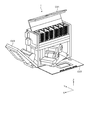
- FIG. 1 is a diagram illustrating an example of an external appearance of the blood collection tube preparing apparatus according to the first embodiment.
- FIG. 2 is a diagram illustrating an example of an external appearance of the blood collection tube preparing apparatus according to the first embodiment.
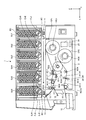
- FIG. 3 is a diagram illustrating a configuration example of the blood collection tube preparing apparatus according to the first embodiment.
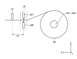
- FIG. 4 is a diagram illustrating a common configuration of the automatic printing device and the hand-pasted printing device according to the first embodiment.
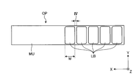
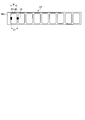
- FIG. 5 is a diagram illustrating an example of the configuration of continuous paper according to the first exemplary embodiment.
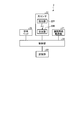
- FIG. 6 is a functional block diagram showing a configuration example of the label printing apparatus according to the first embodiment.
- FIG. 1 is a diagram illustrating an example of an external appearance of the blood collection tube preparing apparatus according to the first embodiment.
- FIG. 2 is a diagram illustrating an example of an external appearance of the blood collection tube preparing apparatus according to the first embodiment.
- FIG. 3 is a diagram illustrating a configuration example
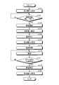
- FIG. 7 is a flowchart for explaining a processing example of the label printing apparatus according to the first embodiment.
- FIG. 8 is a diagram for explaining an operation example of the label printing apparatus according to the first embodiment.
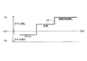
- FIG. 9 is a diagram for explaining an operation example of the label printing apparatus according to the first embodiment.
- FIG. 10 is a diagram for explaining an operation example of the label printing apparatus according to the first embodiment.
- FIG. 11 is a diagram for explaining an operation example of the label printing apparatus according to the first embodiment.
- FIG. 12 is a flowchart for explaining a processing example of the label printing apparatus according to the first embodiment.
- FIG. 13 is a diagram for explaining an operation example of the label printing apparatus according to the first embodiment.
- FIG. 14 is a flowchart for explaining a processing example of the label printing apparatus according to the second embodiment.
- FIG. 15 is a diagram for explaining an operation example of the label printing apparatus according to the second embodiment.
- FIG. 16 is a diagram for explaining an operation example of the label printing apparatus according to the second embodiment.
- FIG. 17 is a diagram for explaining an operation example of the label printing apparatus according to the second embodiment.
- FIG. 1 shows the appearance when the covers CV1, CV2, CV3 are closed
- FIG. 2 shows the appearance when the covers CV1, CV2, CV3 are opened.
- FIG. 3 is a diagram illustrating a configuration example of the blood collection tube preparing apparatus according to the first embodiment.
- the blood collection tube preparation device 1 includes a label printing device 2, blood collection tube supply units SU1 to SU6, blood collection tube feeding units EJ1 to EJ6, a blood collection tube transport unit 11, and blood collection tube guides 12 and 14.
- the label winding unit 13, the take-out tray 15, and the label cutter 16 are provided. It is possible to store a plurality of blood collection tubes BC in each of the blood collection tube supply units SU1 to SU6.
- Each of the blood collection tube feeding sections EJ1 to EJ6 is provided at the lowermost supply port of each of the blood collection tube supply sections SU1 to SU6.
- Each of the blood collection tube feeding sections EJ1 to EJ6 is provided with a recess into which the blood collection tube BC is fitted, and the blood collection tube feeding sections EJ1 to EJ6 are rotated so that the blood collection tube BC fitted in the recess is collected. It falls to 11.
- the blood collection tube supply units SU1 to SU6 may be collectively referred to as “the blood collection tube supply unit SU”
- the blood collection tube output units EJ1 to EJ6 may be collectively referred to as the "blood collection tube output unit EJ”.
- the label printing apparatus 2 includes a control unit 24, a storage unit 25, rollers RO1 to RO10, optical sensors 22-1 and 22-2, and print heads 23-1 and 23-2.
- the optical sensor 22-1 is a transmissive optical sensor having a light projector 22-1T and a light receiver 22-1R
- the optical sensor 22-2 is a light transmission having a light projector 22-2T and a light receiver 22-2R. Type optical sensor.
- the control unit 24 is realized as hardware, for example, by a processor.
- the processor include a CPU (Central Processing Unit), a DSP (Digital Signal Processor), and an FPGA (Field Programmable Gate Array).
- the control unit 24 may be realized by an LSI (Large Scale Integrated circuit) including a processor and peripheral circuits.
- the storage unit 25 is realized as hardware, for example, by a memory.
- Examples of memory include RAM (Random Access Memory) such as SDRAM (Synchronous Dynamic Random Access Memory), ROM (Read Only Memory), and flash memory.
- the label printing device 2 has an “automatic printing device” that automatically winds the printed label around the blood collection tube BC, and a “hand pasting printing device” that discharges the printed label as it is as a label for manual pasting.
- the automatic printing apparatus is composed of rollers RO1 to RO7, an optical sensor 22-1 and a print head 23-1
- the hand pasting printing apparatus is a roller RO8 to RO10 and an optical sensor 22-. 2 and the print head 23-2.
- the operator sets continuous paper CP1 on the roller RO1 and sets continuous paper CP2 on the roller RO8.
- the continuous papers CP1 and CP2 may be collectively referred to as “continuous paper CP”.
- the optical sensors 22-1 and 22-2 may be collectively referred to as “optical sensor 22”, and the print heads 23-1 and 23-2 may be collectively referred to as “print head 23”.
- the light projectors 22-1T and 22-2T may be collectively referred to as “light projector 22T”, and the light receivers 22-1R and 22-2R may be collectively referred to as “light receiver 22R”.
- the light projector 22T is arranged on the upper surface side of the continuous paper CP and the light receiver 22R is arranged on the lower surface side of the continuous paper CP.
- the light projector 22T is arranged on the lower surface side of the continuous paper CP and the continuous paper CP is arranged.
- the light receiver 22R may be disposed on the upper surface side of the.
- FIG. 4 is a diagram showing a common configuration of the automatic printing apparatus and the hand-pasted printing apparatus of the first embodiment.
- the roll-shaped continuous paper CP is set on the rollers RO1 and RO8.
- the light projector 22T and the light receiver 22R are arranged to face each other so as to sandwich the conveyed continuous paper CP from above and below, and the light projected from the light projector 22T and transmitted through the continuous paper CP is received by the light receiver 22R. Received light.
- the print head 23 is arranged at a position at a predetermined distance D1 from the optical sensor 22.
- FIG. 5 is a diagram illustrating an example of the configuration of continuous paper according to the first embodiment.
- the continuous paper CP is formed from a long mount MU and a plurality of labels LB having a width W attached to the mount MU at a constant interval IV.
- the continuous paper CP has a mount portion and a label. There are parts and.
- the blood collection tube transport unit 11 on which the blood collection tube BC is placed moves to a position above the blood collection tube guide 12 and drops the blood collection tube BC onto the blood collection tube guide 12.
- the blood collection tube BC that has fallen onto the blood collection tube guide 12 rolls down on the blood collection tube guide 12 and is set on the label winding section 13.
- the label wrapping unit 13 attaches the label, which has been printed by the print head 23-1, onto the blood collection tube BC while wrapping it, and releases the labeled blood collection tube BC toward the blood collection tube guide 14.
- the label cutter 16 cuts the label after printing by the print head 23-2 one by one.
- the label after cutting is discharged to the ejection tray 15 as a label for manual application.
- FIG. 6 is a functional block diagram showing a configuration example of the label printing apparatus according to the first embodiment.
- the label printing apparatus 2 has a continuous paper transport unit 21, an optical sensor 22, a print head 23, a control unit 24, and a storage unit 25.
- the optical sensor 22 has a light projector 22T and a light receiver 22R.
- the automatic printing device has a motor MT1 (not shown) for rotating the rollers RO1 to RO7 (FIG. 3).
- the rollers RO1 to RO7 and the motor MT1 correspond to the continuous paper transport unit 21.
- the continuous paper CP1 set on the roller RO1 is conveyed in the +X direction through the roller RO2, the optical sensor 22-1, the print head 23-1, and the roller RO3, and the positions of the rollers RO4 and RO5 (label At the position of the winding unit 13), the conveying direction is reversed to the ⁇ X direction, passes through the roller RO6, is wound around the roller RO7, and is collected.
- rollers RO1, RO3, RO6 rotate counterclockwise, and the rollers RO2, RO4, RO5, RO7 rotate clockwise. Only the mount MU after the label LB has been peeled off is wound around the roller RO7 and collected.
- controller 24 drives the motor MT1, the rollers RO1 to RO7 rotate and the continuous paper CP1 is conveyed.
- the hand-printing device has a motor MT2 (not shown) that rotates rollers RO8 to RO10 (FIG. 3).
- the rollers RO8 to RO10 and the motor MT2 correspond to the continuous paper transport unit 21.
- the continuous paper CP2 set on the roller RO8 is conveyed to the take-out tray 15 in the +X direction through the roller RO9, the optical sensor 22-2, the print head 23-2, and the roller RO10. Therefore, the rollers RO8 and RO10 rotate counterclockwise, and the roller RO9 rotates clockwise.
- the control unit 24 drives the motor MT2, the rollers RO8 to RO10 rotate and the continuous paper CP2 is conveyed.
- motor MT the motors MT1 and MT2 may be collectively referred to as "motor MT".
- FIGS. 8 to 11 and 13 are diagrams for explaining an operation example of the label printing apparatus of the first embodiment.
- 7 and 8 to 11 show processes and operations related to initial setting when a new continuous paper CP is set in the label printing device 2 (that is, when the continuous paper CP is replaced), and FIGS. Indicates a process/operation at the time of printing the label LB.
- the processing/operation when replacing the continuous paper CP and the processing/operation when printing the label LB will be described separately.
- the portion labeled “label” is the light receiver 22R when the label portion exists between the light projector 22T and the light receiver 22R.
- the amount of light received by the light receiver is indicated by "mounting paper”
- the amount of light received by the light receiving device 22R when there is a paper mount between the light projector 22T and the light receiving device 22R is indicated by "no continuous paper”.
- the marked portion indicates the amount of light received by the light receiver 22R when the continuous paper CP does not exist between the light projector 22T and the light receiver 22R.
- control unit 24 can set the light projection amount of the light projector 22T from the minimum level 0 to the maximum level 255, and when the continuous paper CP does not exist between the light projector 22T and the light receiver 22R, the light projection amount of the light projector 22T. Is 0, the amount of light received by the light receiver 22R is also level 0, and when the amount of light projected by the light projector 22T is level 255, the amount of light received by the light receiver 22R is also level 255. Further, since the output voltage of the photodetector 22R increases in proportion to the level of the amount of light received by the photodetector 22R, the output voltages 0V to 5V of the photodetector 22R on the vertical axis in FIGS. This corresponds to levels 0 to 255 of the amount of received light at 22R.
- step S101 the control unit 24 sets the light projection amount of the light projector 22T to the light projection amount FL1 in a state where the continuous paper CP does not exist between the light projector 22T and the light receiver 22R.
- step S101 the control unit 24 sets, as the light projection amount FL1, the light projection amount at which the amount of light received by the light receiver 22R changes as shown by a graph G1 in FIG. That is, in step S101, the control unit 24 sets the amount of light received by the light receiver 22R to the threshold value TH1 or more when the continuous paper CP does not exist between the light projector 22T and the light receiver 22R, regardless of the type of the continuous paper CP.
- a relatively small light projection amount is set as the light projection amount FL1 such that the light reception amount at the light receiver 22R when the continuous paper CP exists between the light projector 22T and the light receiver 22R is less than the threshold value TH1.
- the threshold value TH1 is a threshold value of the amount of light received by the light receiver 22R, and is a threshold value used to determine whether or not the continuous paper CP exists between the light projector 22T and the light receiver 22R.
- the threshold TH1 is stored in the storage unit 25 in advance and is set to, for example, 3V.
- the control unit 24 determines that the continuous paper CP exists between the light projector 22T and the light receiver 22R (there is continuous paper), and the light receiver 22R receives the continuous paper CP.
- the control unit 24 sets what kind of continuous paper CP is set in the label printing device 2 by setting the light projection amount FL1 at which the amount of light received by the light receiver 22R changes as shown in the graph G1.
- the control unit 24 sets the light projecting amount FL1 in which the amount of light received by the light receiver 22R changes as shown by the graph G1
- the control unit 24 exists between the light projector 22T and the light receiver 22R in the mount portion or the label portion. It becomes difficult to determine which of the two.
- the light projection amount FL1 at which the light reception amount at the light receiver 22R changes as shown in the graph G1 makes it possible to reliably determine whether or not the continuous paper CP exists between the light projector 22T and the light receiver 22R. Is.
- the operator With the light projection amount set to the light projection amount FL1, as shown at time t11 in FIG. 8, the operator points the leading edge of the continuous paper CP set in the label printer 2 toward the optical sensor 22 in the +X direction (continuously).
- the paper CP is manually inserted in the conveying direction.
- the amount of light received by the light receiver 22R with respect to the amount of light projected FL1 is equal to or greater than the threshold TH1 (FIG. 9).
- step S103 the control unit 24 measures the amount of light received by the light receiver 22R, and based on the measured amount of light received and the threshold value TH1, the control unit 24 changes from the state of "no continuous paper” to " It is determined whether or not the state has changed to "Continuous paper present" (FIG. 9).
- the control unit 24 repeats the process of step S103 until the amount of received light changes from the state of "no continuous paper” to the state of "continuous paper” (step S103: No).
- step S103 determines that the continuous paper CP has changed from “absence” to “presence” when the amount of received light that has been above the threshold TH1 decreases and becomes less than the threshold TH1 (step S103: Yes).
- the control unit 103 determines that the continuous paper CP has changed from “absent” to “present”, the positional relationship between the continuous paper CP and the optical sensor 22 is in the state at time t12 in FIG.
- the tip of CP is located between the light projector 22T and the light receiver 22R.
- step S105 the drive of the motor MT is started to convey the continuous paper CP. To start.
- step S107 the control unit 24 determines that the continuous paper CP has changed from the "absence” to the "presence” by a predetermined amount, as shown at the time t13 in FIG.
- the continuous paper CP is conveyed by L1.
- the control unit 24 temporarily stops the transport of the continuous paper CP in the state shown at time t13 in FIG. 8 in step S109.
- step S111 the control unit 24 sets the projection amount of the projector 22T to a projection amount FL2 larger than the projection amount FL1 set in step S101. That is, when the control unit 24 detects that the continuous paper CP exists between the light projector 22T and the light receiver 22R using the light projection amount FL1 set in step S101 (step S103: Yes), The light projection amount of the light projector 22T is changed from the light projection amount FL1 to the light projection amount FL2 (FL1 ⁇ FL2).
- step S111 the control unit 24 sets, as the light projection amount FL2, the light projection amount at which the amount of light received by the light receiver 22R changes as shown by a graph G2 in FIG.
- the control unit 24 controls the amount of light received by the light receiver 22R when the mount portion is present between the light projector 22T and the light receiver 22R, regardless of the type of the continuous paper CP, to be the threshold TH1 (see FIG. 9)
- a relatively large light projecting amount such that the light receiving amount of the light receiving device 22R becomes smaller than the threshold value TH2 when the label portion is present between the light projecting device 22T and the light receiving device 22R. It is set as the light emission amount FL2.
- the threshold value TH2 is a threshold value of the amount of light received by the light receiver 22R, and is a threshold value used to determine whether the mount portion or the label portion is present between the light projector 22T and the light receiver 22R.
- the threshold value TH2 is stored in the storage unit 25 in advance and is set to, for example, 1.3V.
- the control unit 24 determines that there is a label portion between the light emitter 22T and the light receiver 22R (with a label), and the amount of light received by the light receiver 22R. Is greater than or equal to the threshold value TH2, it is determined that there is a mount portion between the light projector 22T and the light receiver 22R (no label). Therefore, the control unit 24 sets the light projection amount FL2 at which the amount of light received by the light receiver 22R changes as shown in the graph G2, so that the continuous paper CP set in the label printing device 2 can be any type.
- the control unit 24 sets the light projection amount FL2 in which the amount of light received by the light receiver 22R changes as shown in the graph G2, whether or not the continuous paper CP exists between the light projector 22T and the light receiver 22R. Will be difficult to judge. That is, the light emission amount FL2 in which the amount of light received by the light receiver 22R changes as shown in the graph G2 surely indicates whether the portion existing between the light emitter 22T and the light receiver 22R is the label portion or the mount portion. It is the amount of light that can be judged.
- control unit 24 restarts the transport of the continuous paper CP in step S113, and transports the continuous paper CP in step S115.
- step S117 the control unit 24 measures the amount of light received by the light receiver 22R, and based on the measured amount of light received and the threshold value TH2, the amount of received light changes from the state of “with label” to the state of “without label”. (FIG. 10), that is, whether the portion existing between the light projector 22T and the light receiver 22R has changed from the label portion to the mount portion is determined.
- the control unit 24 repeats the processing of steps S115 and S117 until the amount of received light changes from the state of “with label” to the state of “without label” (step S117: No).
- Step S117 Yes
- step S119 the conveyance of the continuous paper CP is stopped. Therefore, at the time when the conveyance of the continuous paper CP is stopped in step S119, the positional relationship between the continuous paper CP and the optical sensor 22 is in the state of time t14 in FIG. 8, and the mount portion is formed by the light projector 22T and the light receiver 22R. Located in between.
- step S121 the control unit 24 sets the light projection amount of the light projector 22T in step S101 in the state where the mount portion is present between the light projector 22T and the light receiver 22R (at the time t14 in FIG. 8).
- the projection amount FL3 is set to be larger than the projection amount FL1 set in step S111 and smaller than the projection amount FL2 set in step S111.
- the control unit 24 determines the amount of light projected such that the amount of light received by the light receiver 22R changes as shown in a graph G3 in FIG. 11, for example, a mount portion exists between the light projector 22T and the light receiver 22R.
- the light projection amount FL3 is set so that the output voltage of the light receiver 24R in the above state becomes 2.5V.
- the light receiving amount of the light receiving device 22R when the continuous paper CP does not exist between the light projecting device 22T and the light receiving device 22R becomes equal to or more than the threshold value TH1, and the light projecting device 22T
- the amount of light received at 22R is less than the threshold TH2.
- the control unit 24 (1) detects whether or not the continuous paper CP exists between the light projector 22T and the light receiver 22R, and (2) It is possible to detect both the mount portion and the label portion that are present between the light projector 22T and the light receiver 22R.
- the control unit 24 sets the light emission amount FL3 as follows. That is, as the first process, the control unit 24 sets the initial value of the light emission amount candidate LO to the minimum level 0, and sets the initial value of the light emission amount candidate HI to the maximum level 255. Next, as a second process, the control unit 24 sets the light projection amount of the light projector 22T to the average value of the light projection amount candidate LO and the light projection amount candidate HI, and measures the output voltage of the light receiver 22R. Next, as a third process, the control unit 24 updates the light emission amount candidate LO with the average value set in the second process when the measured output voltage is less than 2.5 V, while measuring the measured output voltage.
- the projected light amount candidate HI is updated with the average value set in the second processing. Then, the control unit 24 repeats the above-described second processing and third processing, and determines the projection amount candidate HI when the absolute value of the difference between the projection amount candidate LO and the projection amount candidate HI becomes 1 or less.
- the light emission amount FL3 is set.
- the control unit 24 prints the label LB using the light projection amount FL3 set in step S121 (FIG. 7). That is, when the processing shown in FIG. 12 is performed, the light projection amount of the light projector 22T is set to the light projection amount FL3.
- step S201 the control unit 24 resets the counter n to 0.
- control unit 24 starts the conveyance of the continuous paper CP in step S203, and conveys the continuous paper CP in step S205.
- step S207 the control unit 24 measures the amount of light received by the light receiver 22R, and based on the measured amount of light received and the threshold value TH1 (FIG. 11), the continuous paper CP is changed from “present” to “absent”.
- Judge whether or not The control unit 103 determines that the continuous paper CP has run out of paper when the amount of received light that has been less than the threshold TH1 increases and becomes equal to or greater than the threshold TH1 (step S207: Yes), and in step S209, continuous printing is performed.
- An error message is output to notify the operator that the paper CP has run out.
- the error message output from the control unit 24 is displayed on, for example, a touch panel (not shown) included in the blood collection tube preparation device 1. Upon outputting the error message, the control unit 24 ends the printing process of the label LB.
- step S207: No when the amount of light received by the light receiver 22R is maintained below the threshold TH1 (step S207: No), the control unit 24 measures and measures the amount of light received by the light receiver 22R in step S211. Based on the amount of received light and the threshold value TH2 (FIG. 11), it is determined whether the portion existing between the light projector 22T and the light receiver 22R has changed from the label portion to the mount portion. The control unit 24 repeats the processing of steps S205, S207, and S211 until the portion existing between the light projector 22T and the light receiver 22R changes from the label portion to the mount portion (step S211: No).
- Step S211 Yes
- step S213 the conveyance of the continuous paper CP is temporarily stopped. Therefore, when the conveyance of the continuous paper CP is temporarily stopped in step S213, the positional relationship between the continuous paper CP and the optical sensor 22 is in the state shown in FIG. 13, and the mount portion is between the light projector 22T and the light receiver 22R. Located in.
- the print head 23 is arranged at a position of a predetermined distance D1 from the optical sensor 22, and the distance D1 is, for example, the lateral width W of the label LB or less, and preferably, The distance D1 is the same as the lateral width W of the label LB.
- the distance D1 is the same as the lateral width W
- the leading end of the label LB coincides with the arrangement position of the print head 23 when the conveyance of the continuous paper CP is temporarily stopped in step S213, as shown in FIG. ..
- step S215 the control unit 24 starts printing on the label LB by the print head 23.
- step S217 the control unit 24 increments the counter n.
- step S219 the control unit 24 determines whether or not the counter n has reached the number of printed sheets N (hereinafter, may be referred to as “designated number of printed sheets”) designated by the operator.
- the operator can specify the number N of prints of the label LB by using a touch panel (not shown) included in the blood collection tube preparation device 1.
- step S219: Yes When the counter n has reached the designated print number N (step S219: Yes), the control unit 24 ends the printing process of the label LB. On the other hand, when the counter n is less than the designated number of prints N (step S219: No), the controller 24 restarts the conveyance of the continuous paper CP in step S221. After the restart of the conveyance of the continuous paper CP, the process returns to step S205.
- the label printing device 2 has the continuous paper transport unit 21, the print head 23, the optical sensor 22, and the control unit 24.
- the continuous paper transport unit 21 transports the continuous paper CP.
- the continuous paper CP is formed of a long mount MU and a plurality of labels LB attached to the mount MU at a constant interval IV, and has a mount portion and a label portion.
- the print head 23 prints on each of the plurality of labels LB.
- the optical sensor 22 includes a light projector 22T that projects light and a light receiver 22R that receives the light projected from the light projector 22T.
- the control unit 24 sets the light projection amount of the light projector 22T to the light projection amount FL1 in a state where the continuous paper CP does not exist between the light projector 22T and the light receiver 22R. Further, when the control unit 24 detects that the continuous paper CP exists between the light projector 22T and the light receiver 22R using the light projection amount FL1, the control unit 24 sets the light projection amount of the light projector 22T to be larger than the light projection amount FL1. Set to FL2.
- control unit 24 when the control unit 24 detects that the mount portion exists between the light projector 22T and the light receiver 22R using the light projection amount FL2, the control unit 24 sets the light projection amount of the light projector 22T to be larger than the light projection amount FL1 and The projection amount FL3 is set to be smaller than the projection amount FL2.
- the threshold value for the amount of light received by the light receiver 22R is fixed, the amount of light projected by the light projector 22T can be automatically adjusted to an appropriate amount of light FL3 according to the type of the continuous paper CP. Therefore, the labor of the operator at the time of exchanging the continuous paper CP can be reduced.
- control unit 24 sets the amount of light received by the light receiver 22R to the threshold TH1 or more when the continuous paper CP does not exist between the light projector 22T and the light receiver 22R, regardless of the type of the continuous paper CP. Further, the light projection amount FL1 is set such that the light reception amount at the light receiver 22R when the continuous paper CP exists between the light projector 22T and the light receiver 22R is less than the threshold value TH1.
- the control unit 24 sets the threshold value TH2 (TH2 ⁇ TH2 ⁇ TH2 ⁇ TH2 ⁇ TH2 ⁇ TH2 ⁇ TH2 ⁇ TH2 ⁇ TH2 ⁇ TH2 ⁇ when the mount portion is present between the light projector 22T and the light receiver 22R regardless of the type of the continuous paper CP. TH1) or more, and when the label portion exists between the light emitter 22T and the light receiver 22R, the light quantity received by the light receiver 22R becomes less than the threshold value TH2, and is set as the light quantity FL2.
- control unit 24 causes the continuous paper transport unit to respond in response to the amount of light received by the light receiver 22R of the light projected by the light projector 22T having the light projection amount FL3 increasing from less than the threshold value TH2 to more than the threshold value TH2.
- the conveyance of the continuous paper CP by 21 is stopped, and the printing on the label LB by the print head 23 is started.
- control unit 24 causes the continuous paper CP to run out when the amount of light received by the light receiver 22R of the light projected by the light projector 22T at the light projection amount FL3 increases from less than the threshold value TH1 to more than the threshold value TH1. Is determined to have occurred.
- Example 2 In the first embodiment, the case has been described where the light projection amount is set while the threshold value of the light reception amount is kept constant. On the other hand, in the second embodiment, a case will be described in which the threshold value of the received light amount is set until the projected light amount is constant. The points different from the first embodiment will be described below.
- FIG. 14 is a flowchart for explaining a processing example of the label printing apparatus of the second embodiment
- FIGS. 15 to 17 are diagrams for explaining an operation example of the label printing apparatus of the second embodiment. 14 to 17 show processes and operations related to initial setting when a new continuous paper CP is set in the label printing device 2 (that is, when the continuous paper CP is replaced). In the following, the processing/operation when replacing the continuous paper CP and the processing/operation when printing the label LB will be described separately.
- the portion labeled “label” indicates the amount of light received by the light receiver 22R when the label portion is present between the light projector 22T and the light receiver 22R.
- the portion labeled “mounting paper” indicates the amount of light received by the light receiver 22R when there is a mounting portion between the projector 22T and the light receiver 22R, and the portion marked "no continuous paper” , Shows the amount of light received by the light receiver 22R when the continuous paper CP does not exist between the light projector 22T and the light receiver 22R.
- step S301 the control unit 24 sets the light projection amount of the light projector 22T to a predetermined light projection amount FL4 in a state where the continuous paper CP does not exist between the light projector 22T and the light receiver 22R, and then receives light.
- a threshold TH3 for the amount of light received by the device 22R is set.
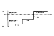
- the control unit 24 sets a predetermined light projecting amount FL4 at which the amount of light received by the light receiver 22R changes as shown by a graph G4 in FIG. 15, and then sets a threshold value TH3.
- step S301 the control unit 24 controls the light receiver 22R when the continuous paper CP does not exist between the light projector 22T and the light receiver 22R under the predetermined light projection amount FL4 regardless of the type of the continuous paper CP.
- a relatively large threshold value such that the amount of light received by the light receiver 22R is less than the threshold value TH3 and the amount of light received by the light receiver 22R when the continuous paper CP exists between the light projector 22T and the light receiver 22R is less than the threshold value TH3.
- the threshold TH3 is a threshold used to determine whether or not the continuous paper CP exists between the light projector 22T and the light receiver 22R.
- the controller 24 determines that the continuous paper CP exists between the light projector 22T and the light receiver 22R (there is continuous paper), and the light receiver 22R receives the continuous paper CP.
- the control unit 24 sets the threshold value TH3 after setting the light projection amount FL4 at which the amount of light received by the light receiver 22R changes as shown in the graph G4, so that the continuous paper CP set in the label printing apparatus 2 is set.
- the threshold value TH3 is a threshold value that can reliably determine whether or not the continuous paper CP exists between the light projector 22T and the light receiver 22R.
- the operator moves the leading edge of the continuous paper CP set in the label printing apparatus 2 toward the optical sensor 22 in the +X direction (transportation of the continuous paper CP). Direction) by hand.
- the positional relationship between the continuous paper CP and the optical sensor 22 is at time t11, the amount of light received by the light receiver 22R with respect to the amount of light projection FL4 is equal to or greater than the threshold TH3 (FIG. 15).
- step S103 the control unit 24 measures the amount of light received by the light receiver 22R, and based on the measured amount of light received and the threshold value TH3, the amount of received light is changed from the state of "no continuous paper” to " It is determined whether or not the state has changed to the state of "continuous paper is present" (FIG. 15).
- the control unit 24 repeats the process of step S103 until the amount of received light changes from the state of "no continuous paper” to the state of "continuous paper” (step S103: No).
- control unit 103 determines that the continuous paper CP has changed from “absence” to “presence” when the amount of received light, which has been above the threshold TH3, decreases below the threshold TH3 (step S103: Yes). .. Therefore, at the time when the control unit 103 determines that the continuous paper CP has changed from “absent” to “present”, the positional relationship between the continuous paper CP and the optical sensor 22 is in the state at time t12 in FIG. The tip of CP is located between the light projector 22T and the light receiver 22R.
- steps S105 to S109 Since the processing of steps S105 to S109 is the same as that of the first embodiment, the description is omitted.
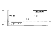
- step S303 the control unit 24 sets a threshold value TH4 (TH4 ⁇ TH3) for the amount of light received by the light receiver 22R, as shown in FIG. 16, while maintaining the amount of light projected by the light projector 22T at a predetermined light projection amount FL4. .. That is, when the control unit 24 detects that the continuous paper CP exists between the light projector 22T and the light receiver 22R using the threshold TH3 set in step S301 (step S103: Yes), the threshold is set. Set TH4. In step S303, the control unit 24 receives light at the light receiver 22R when the mount portion exists between the light projector 22T and the light receiver 22R under the predetermined light projection amount FL4 regardless of the type of the continuous paper CP.
- TH4 TH4 ⁇ TH3
- the amount becomes equal to or larger than the threshold TH4 which is smaller than the threshold TH3 (FIG. 15), and the amount of light received by the light receiver 22R when the label portion is present between the light emitter 22T and the light receiver 22R becomes less than the threshold TH4.
- a relatively small threshold is set as the threshold TH4.
- the threshold value TH4 is a threshold value used to determine whether the mount portion or the label portion is present between the light projector 22T and the light receiver 22R.
- the control unit 24 determines that a label portion exists between the light emitter 22T and the light receiver 22R (with a label), and the amount of light received by the light receiver 22R.
- the control unit 24 sets the threshold value TH4 after setting the light projection amount FL4 at which the amount of light received by the light receiver 22R changes as shown in the graph G4, so that the continuous paper CP set in the label printing device 2 is set. Regardless of the type of continuous paper CP, whether it is the label portion or the mount portion that exists between the light projector 22T and the light receiver 22R based on the threshold value TH4 regardless of the type. You can judge.
- the threshold value TH4 is a threshold value with which it is possible to reliably determine whether the portion existing between the light projector 22T and the light receiver 22R is the label portion or the mount portion.
- control unit 24 restarts the conveyance of the continuous paper CP in step S113, and conveys the continuous paper CP in step S115.
- step S117 the control unit 24 measures the amount of light received by the light receiver 22R, and based on the measured amount of received light and the threshold value TH4, the amount of received light is changed from the "labeled" state to the "unlabeled” state. (FIG. 16), that is, whether the portion existing between the light projector 22T and the light receiver 22R has changed from the label portion to the mount portion is determined.
- the control unit 24 repeats the processing of steps S115 and S117 until the amount of received light changes from the state of “with label” to the state of “without label” (step S117: No).
- step S119 the conveyance of the continuous paper CP is stopped. Therefore, at the time when the conveyance of the continuous paper CP is stopped in step S119, the positional relationship between the continuous paper CP and the optical sensor 22 is in the state of time t14 in FIG. 8, and the mount portion is formed by the light projector 22T and the light receiver 22R. Located in between.
- step S119 Since the process of step S119 is the same as that of the first embodiment, the description will be omitted.
- step S305 the control unit 24 maintains the light projection amount of the light projector 22T at a predetermined light projection amount FL4 in a state where the mount portion is present between the light projector 22T and the light receiver 22R (at the time t14 in FIG. 8).
- the thresholds TH3 and TH4 instead of the thresholds TH3 and TH4, as shown in FIG. 17, the thresholds TH5 and TH6 with respect to the amount of light received by the light receiver 22R are set.
- the threshold value TH5 is a threshold value used to determine whether or not the continuous paper CP exists between the light projector 22T and the light receiver 22R, and the threshold value TH6 is a portion existing between the light projector 22T and the light receiver 22R.
- the control unit 24 in the light receiving amount that changes as shown by the graph G4 under the predetermined light emitting amount FL4, the light receiving amount when the continuous paper CP does not exist between the light projecting device 22T and the light receiving device 22R, and the light projecting device 22T.
- the threshold value TH5 is set to the average value of the amount of light received when there is a mount between the light receiver 22R and the light receiver 22R.
- the control unit 24, in the received light amount that changes as shown by the graph G4 under the predetermined projected light amount FL4 the received light amount when the mount portion is present between the projectors 22T and 22R, and the projector 22T.
- the threshold value TH6 is set to the average value of the amount of light received when there is a label portion between the light receiver 22R and the light receiver 22R.
- the thresholds TH5 and TH6 are set as the thresholds of the amount of light received by the light receiver 22R.
- the continuous paper CP is provided between the light projector 22T and the light receiver 22R when the light projection amount of the light projector 22T is the predetermined light projection amount FL4.
- the amount of light received by the light receiver 22R is greater than or equal to the threshold value TH5
- the mount portion is between the light projector 22T and the light receiver 22R
- the amount of light received by the light receiver 22R is greater than or equal to the threshold value TH6 and less than the threshold value TH5.
- the amount of light received by the light receiver 22R when the label portion exists between the light projector 22T and the light receiver 22R is less than the threshold value TH6. That is, by setting the thresholds TH5 and TH6, the control unit 24 detects (1) whether or not the continuous paper CP exists between the light projector 22T and the light receiver 22R, as in the first embodiment. Further, (2) it becomes possible to detect both the portion existing between the light projector 22T and the light receiver 22R, which is the mount portion or the label portion.
- the control unit 24 prints the label LB using the thresholds TH5 and TH6 (FIG. 17) set in step S305 (FIG. 14). Further, when the processing shown in FIG. 12 is performed, the light projection amount of the light projector 22T is set to a predetermined light projection amount FL4.
- steps S201 to S205 are the same as that of the first embodiment, and therefore the description thereof is omitted.
- step S207 the control unit 24 measures the amount of light received by the light receiver 22R, and based on the measured amount of light received and the threshold value TH5 (FIG. 17), the continuous paper CP is changed from “present” to “absent”. Determine whether or not The control unit 103 determines that the continuous paper CP has run out when the amount of received light that is less than the threshold TH5 increases and becomes equal to or greater than the threshold TH5 (step S207: Yes), and in step S209, the continuous printing is performed. An error message is output to notify the operator that the paper CP has run out. The error message output from the control unit 24 is displayed on, for example, a touch panel (not shown) included in the blood collection tube preparation device 1. Upon outputting the error message, the control unit 24 ends the printing process of the label LB.
- step S207: No when the amount of light received by the light receiver 22R is maintained below the threshold value TH5 (step S207: No), the control unit 24 measures and measures the amount of light received by the light receiver 22R in step S211. Based on the amount of received light and the threshold value TH6 (FIG. 17), it is determined whether the portion existing between the light projector 22T and the light receiver 22R has changed from the label portion to the mount portion. The control unit 24 repeats the processing of steps S205, S207, and S211 until the portion existing between the light projector 22T and the light receiver 22R changes from the label portion to the mount portion (step S211: No).
- Step S211 Yes
- step S213 the conveyance of the continuous paper CP is temporarily stopped. Therefore, when the conveyance of the continuous paper CP is once stopped in step S213, the positional relationship between the continuous paper CP and the optical sensor 22 is in the state of FIG. 13, and the mount portion is between the light projector 22T and the light receiver 22R. To position.
- steps S215 to S221 are the same as those in the first embodiment, the description thereof will be omitted.
- the label printing apparatus 2 has the continuous paper transport unit 21, the print head 23, the optical sensor 22, and the control unit 24.
- the continuous paper transport unit 21 transports the continuous paper CP.
- the continuous paper CP is formed of a long mount MU and a plurality of labels LB attached to the mount MU at a constant interval IV, and has a mount portion and a label portion.
- the print head 23 prints on each of the plurality of labels LB.
- the optical sensor 22 includes a light projector 22T that projects light and a light receiver 22R that receives the light projected from the light projector 22T.
- the control unit 24 sets the threshold value TH3 in a state where the continuous paper CP does not exist between the light projector 22T and the light receiver 22R.
- control unit 24 sets the threshold value TH4 when detecting that the continuous paper CP exists between the light projector 22T and the light receiver 22R using the threshold value TH3. Further, when the control unit 24 detects that the mount portion exists between the light projector 22T and the light receiver 22R using the threshold value TH4, the control unit 24 replaces the threshold value TH3 with the light emitter 22T and the light receiver 22R.
- the average value of the amount of light received when the continuous paper CP does not exist and the amount of light received when the mount portion exists between the light projector 22T and the light receiver 22R is set as the threshold value TH5, and instead of the threshold value TH4, the light projector is set.
- the threshold value TH6 is set as an average value of the amount of light received when the mount portion is present between the 22T and the light receiver 22R and the amount of light received when the label portion is present between the light projector 22T and the light receiver 22R.
- the threshold value for the light reception amount of the light receiver 22R is automatically adjusted to appropriate threshold values TH5 and TH6 according to the type of the continuous paper CP. Therefore, it is possible to reduce the labor of the operator when exchanging the continuous paper CP.
- control unit 24 stops the conveyance of the continuous paper CP by the continuous paper conveyance unit 21 and prints when the amount of light received by the light receiver 22R increases from less than the threshold value TH6 to more than the threshold value TH6. Printing on the label LB by the head 23 is started.
- control unit 24 determines that the continuous paper CP has run out when the amount of light received by the light receiver 22R increases from less than the threshold TH5 to more than the threshold TH5.
- All or part of each processing in the above description in the control unit 24 may be realized by causing a processor included in the label printing apparatus 2 to execute a program corresponding to each processing.
- a program corresponding to each process described above may be stored in the memory, and the program may be read from the memory by the processor and executed.
- the program is stored in a program server connected to the label printing device 2 via an arbitrary network, downloaded from the program server to the label printing device 2 and executed, or a record readable by the label printing device 2. It may be stored in a medium, read from the recording medium, and executed.
- the recording medium readable by the label printing device 2 may be, for example, a memory card, a USB memory, an SD card, a flexible disk, a magneto-optical disk, a CD-ROM, a DVD, a Blu-ray (registered trademark) disk, or the like.
- a portable storage medium is included.
- the program is a data processing method described in any language or any description method, and may take any form such as source code or binary code. Further, the program is not necessarily limited to a single configuration, and achieves its function in cooperation with a plurality of modules or a plurality of libraries distributedly configured, or with a separate program represented by an OS. Including things.
- the specific form of the dispersion/integration of the blood collection tube preparation apparatus 1 and the label printing apparatus 2 is not limited to that shown in the figure, and all or part of the blood collection tube preparation apparatus 1 and the label printing apparatus 2 may be added according to various additions. Alternatively, it can be functionally or physically distributed and integrated in arbitrary units according to the functional load.
- label printing device 21 continuous paper transport unit 22 optical sensor 22T light projector 22R light receiver 23 print head 24 control unit 25 storage unit
Landscapes
- Controlling Sheets Or Webs (AREA)
- Handling Of Sheets (AREA)
- Labeling Devices (AREA)
Abstract
連続用紙の交換時のオペレータの手間を低減することができるラベル印字装置。ラベル印字装置(2)において、光センサ(22)は、光を投光する投光器(22T)と、投光器(22T)から投光された光を受光する受光器(22R)とを有する。制御部(24)は、投光器(22T)と受光器(22R)との間に連続用紙(CP)が存在しない状態で、投光器(22T)の投光量を投光量FL1に設定し、投光量FL1を用いて連続用紙(CP)が投光器(22T)と受光器(22R)との間に存在することを検出するときに、投光器(22T)の投光量を、投光量FL1より大きい投光量FL2に設定し、投光量FL2を用いて台紙部分が投光器(22T)と受光器(22R)との間に存在することを検出するときに、投光器(22T)の投光量を、投光量FL1より大きく、かつ、投光量FL2より小さい投光量FL3に設定する。
Description
開示の技術は、ラベル印字装置、投光量設定方法及び閾値設定方法に関する。
長尺状の台紙と、その台紙に一定の間隔で貼付された複数のラベルとから形成される連続用紙を印字対象とし、連続用紙を搬送しながら、台紙に貼付された複数のラベルの各々に印字を行う「ラベル印字装置」が知られている。印字対象となる連続用紙では一定間隔でラベルが台紙に貼付されているため、連続用紙には、台紙が存在する一方でラベルが存在しない部分(以下では「台紙部分」と呼ぶことがある)と、台紙及びラベルの双方が存在する部分(以下では「ラベル部分」と呼ぶことがある)とが存在する。ラベル印字装置は、例えば、医療機関で用いられる採血管に貼付されるラベルに患者名等を印字するために用いられる。
また、ラベルへの印字は印字ヘッドにより行われるため、ラベルへの印字を開始するにあたり、連続用紙の搬送に伴って、ラベルの先端を印字ヘッドが配置されている位置(以下では「印字ヘッド配置位置」と呼ぶことがある)に合わせる必要がある。連続用紙に対して連続用紙の上面または下面から光を投光したときの台紙部分における光の透過率(以下では「台紙部分透過率」と呼ぶことがある)は、ラベル部分における光の透過率(以下では「ラベル部分透過率」と呼ぶことがある)よりも大きい。また、台紙には一定間隔でラベルが貼付されている。このため、透過型光センサを使用し、投光器から投光された光の受光器における受光量が所定の範囲にあるときを、搬送される連続用紙における台紙部分が透過型光センサが配置されている位置(以下では「光センサ配置位置」と呼ぶことがある)にあるときとして判断することにより、連続用紙における台紙部分を検出することができる。そして、印字ヘッドから所定の距離に配置された透過型光センサを用いて台紙部分を検出したときに連続用紙の搬送を停止することにより、印字ヘッド配置位置にラベルの先端を合わせることができる。
ラベル印字装置にセットされる連続用紙には様々な種類のものがあるため、連続用紙毎に台紙部分透過率が異なる。このため、透過型光センサの投光器からの光の投光量を連続用紙の種類にかかわらず一定にしたままでは、連続用紙の種類に応じて、台紙部分における受光器での光の受光量が変化してしまう。よって、上記のようにして受光器での受光量に基づいて台紙部分を検出するラベル印字装置にセットされる連続用紙が異なった種類のものに交換されたのにもかかわらず、投光器からの光の投光量が連続用紙の種類にかかわらず一定にされたままでは、台紙部分を正しく検出できないことがある。そこで、オペレータは、連続用紙を交換する度に、ラベルの印字を開始する前の初期設定として、連続用紙の種類によらず台紙部分での受光量が一定になるように、投光器からの光の投光量を手動で調節していた。このようなオペレータによる手動での投光量の調節は、オペレータにとって手間がかかる作業である。一方で、連続用紙の種類に応じた投光量の調節が行われなければ、台紙部分を正しく検出できなくなってしまうことがある。
開示の技術は、上記に鑑みてなされたものであって、連続用紙の交換時のオペレータの手間を低減することを目的とする。
開示の第一の態様では、ラベル印字装置は、搬送部と、印字ヘッドと、光センサと、制御部とを有する。前記搬送部は、連続用紙を搬送する。前記連続用紙は、長尺状の台紙と、前記台紙に一定の間隔で貼付された複数のラベルとから形成され、前記台紙が存在する一方で前記ラベルが存在しない第一部分と、前記台紙及び前記ラベルの双方が存在する第二部分とを有する。前記印字ヘッドは、前記複数のラベルの各々に印字を行う。前記光センサは、光を投光する投光器と、前記投光器から投光された前記光を受光する受光器とを有する。前記制御部は、前記投光器と前記受光器との間に前記連続用紙が存在しない状態で、前記投光器の投光量を第一投光量に設定する。また、前記制御部は、前記第一投光量を用いて前記連続用紙が前記投光器と前記受光器との間に存在することを検出するときに、前記投光量を、前記第一投光量より大きい第二投光量に設定する。また、前記制御部は、前記第二投光量を用いて前記第一部分が前記投光器と前記受光器との間に存在することを検出するときに、前記投光量を、前記第一投光量より大きく、かつ、前記第二投光量より小さい前記第三投光量に設定する。
また、開示の第二の態様では、ラベル印字装置は、搬送部と、印字ヘッドと、光センサと、制御部とを有する。前記搬送部は、連続用紙を搬送する。前記連続用紙は、長尺状の台紙と、前記台紙に一定の間隔で貼付された複数のラベルとから形成され、前記台紙が存在する一方で前記ラベルが存在しない第一部分と、前記台紙及び前記ラベルの双方が存在する第二部分とを有する。前記印字ヘッドは、前記複数のラベルの各々に印字を行う。前記光センサは、光を投光する投光器と、前記投光器から投光された前記光を受光する受光器とを有する。前記制御部は、前記投光器と前記受光器との間に前記連続用紙が存在しない状態で、前記受光器での受光量に対する第一閾値であって、前記連続用紙の種類にかかわらず前記投光器と前記受光器との間に前記連続用紙が存在する否かを判断するために用いられる前記第一閾値を設定する。また、前記制御部は、前記第一閾値を用いて前記連続用紙が前記投光器と前記受光器との間に存在することを検出するときに、前記受光量に対する第二閾値であって、前記第一閾値より小さく、かつ、前記連続用紙の種類にかかわらず前記投光器と前記受光器との間に前記第一部分または前記第二部分の何れが存在するかを判断するために用いられる前記第二閾値を設定する。また、前記制御部は、前記第二閾値を用いて前記第一部分が前記投光器と前記受光器との間に存在することを検出するときに、前記第一閾値に代えて、前記投光器と前記受光器との間に前記連続用紙が存在しないときの前記受光器での第一受光量と、前記投光器と前記受光器との間に前記第一部分が存在するときの前記受光器での第二受光量との平均値を、前記投光器と前記受光器との間に前記連続用紙が存在する否かを判断するために用いられる第三閾値として設定する。また、前記制御部は、前記第二閾値を用いて前記第一部分が前記投光器と前記受光器との間に存在することを検出するときに、前記第二閾値に代えて、前記第二受光量と、前記投光器と前記受光器との間に前記第二部分が存在するときの前記受光器での第三受光量との平均値を、前記投光器と前記受光器との間に前記第一部分または前記第二部分の何れが存在するかを判断するために用いられる第四閾値として設定する。
開示の態様によれば、連続用紙の交換時のオペレータの手間を低減することができる。
以下に、本願の開示するラベル印字装置、投光量設定方法及び閾値設定方法の実施例を図面に基づいて説明する。なお、この実施例により本願の開示するラベル印字装置、投光量設定方法及び閾値設定方法が限定されるものではない。また、実施例において同一の構成、及び、同一の処理を行うステップには同一の符号を付す。
[実施例1]
<採血管準備装置の外観>
図1及び図2は、実施例1の採血管準備装置の外観の一例を示す図である。図1及び図2において、採血管準備装置1は、開閉可能なカバーCV1,CV2,CV3を有する。図1には、カバーCV1,CV2,CV3が閉められているときの外観を示し、図2には、カバーCV1,CV2,CV3が開けられているときの外観を示す。
<採血管準備装置の外観>
図1及び図2は、実施例1の採血管準備装置の外観の一例を示す図である。図1及び図2において、採血管準備装置1は、開閉可能なカバーCV1,CV2,CV3を有する。図1には、カバーCV1,CV2,CV3が閉められているときの外観を示し、図2には、カバーCV1,CV2,CV3が開けられているときの外観を示す。
<採血管準備装置の構成>
図3は、実施例1の採血管準備装置の構成例を示す図である。図3において、採血管準備装置1は、ラベル印字装置2と、採血管供給部SU1~SU6と、採血管操出部EJ1~EJ6と、採血管搬送部11と、採血管ガイド12,14と、ラベル巻付部13と、取出トレイ15と、ラベルカッター16とを有する。採血管供給部SU1~SU6の各々には、複数の採血管BCを格納することが可能である。採血管操出部EJ1~EJ6の各々は、採血管供給部SU1~SU6の各々の最下部の供給口に設けられる。採血管操出部EJ1~EJ6の各々には採血管BCが嵌まる凹部が設けられ、採血管操出部EJ1~EJ6が回転することにより、凹部に嵌まった採血管BCが採血管搬送部11に落下する。以下では、採血管供給部SU1~SU6を「採血管供給部SU」と総称し、採血管操出部EJ1~EJ6を「採血管操出部EJ」と総称することがある。
図3は、実施例1の採血管準備装置の構成例を示す図である。図3において、採血管準備装置1は、ラベル印字装置2と、採血管供給部SU1~SU6と、採血管操出部EJ1~EJ6と、採血管搬送部11と、採血管ガイド12,14と、ラベル巻付部13と、取出トレイ15と、ラベルカッター16とを有する。採血管供給部SU1~SU6の各々には、複数の採血管BCを格納することが可能である。採血管操出部EJ1~EJ6の各々は、採血管供給部SU1~SU6の各々の最下部の供給口に設けられる。採血管操出部EJ1~EJ6の各々には採血管BCが嵌まる凹部が設けられ、採血管操出部EJ1~EJ6が回転することにより、凹部に嵌まった採血管BCが採血管搬送部11に落下する。以下では、採血管供給部SU1~SU6を「採血管供給部SU」と総称し、採血管操出部EJ1~EJ6を「採血管操出部EJ」と総称することがある。
また、図3において、ラベル印字装置2は、制御部24と、記憶部25と、ローラRO1~RO10と、光センサ22-1,22-2と、印字ヘッド23-1,23-2とを有する。光センサ22-1は、投光器22-1Tと、受光器22-1Rとを有する透過型光センサであり、光センサ22-2は、投光器22-2Tと、受光器22-2Rとを有する透過型光センサである。
制御部24は、ハードウェアとして、例えばプロセッサにより実現される。プロセッサの一例として、CPU(Central Processing Unit)、DSP(Digital Signal Processor)、FPGA(Field Programmable Gate Array)等が挙げられる。また、制御部24は、プロセッサと周辺回路とを含むLSI(Large Scale Integrated circuit)によって実現されても良い。
記憶部25は、ハードウェアとして、例えば、メモリにより実現される。メモリの一例として、SDRAM(Synchronous Dynamic Random Access Memory)等のRAM(Random Access Memory)、ROM(Read Only Memory)、フラッシュメモリ等が挙げられる。
ラベル印字装置2は、印字後のラベルを自動で採血管BCに巻き付ける「自動印字装置」と、印字後のラベルを手貼用のラベルとしてそのまま排出する「手貼印字装置」とを有する。ラベル印字装置2において、自動印字装置は、ローラRO1~RO7と、光センサ22-1と、印字ヘッド23-1とから構成され、手貼印字装置は、ローラRO8~RO10と、光センサ22-2と、印字ヘッド23-2とから構成される。オペレータによって、ローラRO1には連続用紙CP1がセットされ、ローラRO8には連続用紙CP2がセットされる。以下では、連続用紙CP1,CP2を「連続用紙CP」と総称することがある。また、以下では、光センサ22-1,22-2を「光センサ22」と総称し、印字ヘッド23-1,23-2を「印字ヘッド23」と総称することがある。また、投光器22-1T,22-2Tを「投光器22T」と総称し、受光器22-1R,22-2Rを「受光器22R」と総称することがある。図3では、連続用紙CPの上面側に投光器22Tが配置され、連続用紙CPの下面側に受光器22Rが配置されているが、連続用紙CPの下面側に投光器22Tを配置し、連続用紙CPの上面側に受光器22Rを配置しても良い。
図4は、実施例1の自動印字装置と手貼印字装置との共通な構成を示す図である。図4に示すように、ロール状の連続用紙CPが、ローラRO1,RO8にセットされる。光センサ22において、搬送される連続用紙CPを上下から挟むようにして投光器22Tと受光器22Rとが互いに対向して配置され、投光器22Tから投光され、連続用紙CPを透過した光が受光器22Rにより受光される。また、光センサ22から所定の距離D1の位置に印字ヘッド23が配置される。
図5は、実施例1の連続用紙の構成の一例を示す図である。図5において、連続用紙CPは、長尺状の台紙MUと、台紙MUに一定の間隔IVで貼付された横幅Wの複数のラベルLBとから形成され、連続用紙CPには、台紙部分とラベル部分とが存在する。
<採血管準備装置の動作>
以下、自動印字装置が使用される場合の動作と、手貼印字装置が使用される場合の動作とに分けて説明する。
以下、自動印字装置が使用される場合の動作と、手貼印字装置が使用される場合の動作とに分けて説明する。
<自動印字装置が使用される場合の採血管準備装置の動作>
まず、採血管供給部SU1~SU6のうちオペレータにより指定された採血管供給部SUに設けられている採血管操出部EJが、採血管供給部SUから採血管BCを繰り出して採血管搬送部11に落下させる。
まず、採血管供給部SU1~SU6のうちオペレータにより指定された採血管供給部SUに設けられている採血管操出部EJが、採血管供給部SUから採血管BCを繰り出して採血管搬送部11に落下させる。
採血管BCを載せた採血管搬送部11は、採血管ガイド12の上まで移動して採血管BCを採血管ガイド12に落下させる。採血管ガイド12に落下した採血管BCは、採血管ガイド12を転がり落ちてラベル巻付部13にセットされる。
ラベル巻付部13は、印字ヘッド23-1による印字後のラベルを採血管BCに巻き付けながら貼り付け、ラベル貼付後の採血管BCを採血管ガイド14に向かって放出する。採血管ガイド14に向かって放出された採血管BCは、採血管ガイド14を転がり落ちて取出トレイ15に落下し、取出トレイ15に排出される。
<手貼印字装置が使用される場合の採血管準備装置の動作>
ラベルカッター16は、印字ヘッド23-2による印字後のラベルを1枚ずつカットする。カット後のラベルは、手貼用のラベルとして取出トレイ15に排出される。
ラベルカッター16は、印字ヘッド23-2による印字後のラベルを1枚ずつカットする。カット後のラベルは、手貼用のラベルとして取出トレイ15に排出される。
<ラベル印字装置の構成>
上記のように、ラベル印字装置2において、自動印字装置と手貼印字装置とは図4に示すような共通な構成を有するため、以下では、自動印字装置と手貼印字装置とを「ラベル印字装置2」と総称して説明する。
上記のように、ラベル印字装置2において、自動印字装置と手貼印字装置とは図4に示すような共通な構成を有するため、以下では、自動印字装置と手貼印字装置とを「ラベル印字装置2」と総称して説明する。
図6は、実施例1のラベル印字装置の構成例を示す機能ブロック図である。図6において、ラベル印字装置2は、連続用紙搬送部21と、光センサ22と、印字ヘッド23と、制御部24と、記憶部25とを有する。光センサ22は、投光器22Tと受光器22Rとを有する。
自動印字装置は、ローラRO1~RO7(図3)を回転させるモータMT1(図示省略)を有する。自動印字装置においては、ローラRO1~RO7及びモータMT1が連続用紙搬送部21に相当する。自動印字装置では、ローラRO1にセットされた連続用紙CP1は、ローラRO2、光センサ22-1、印字ヘッド23-1、ローラRO3を通って+X方向へ搬送され、ローラRO4,RO5の位置(ラベル巻付部13の位置)で搬送方向を-X方向に反転され、ローラRO6を通り、ローラRO7に巻き付けられて回収される。よって、ローラRO1,RO3,RO6は左回りに回転し、ローラRO2,RO4,RO5,RO7は右回りに回転する。ローラRO7に巻き付けられて回収されるのは、ラベルLBが剥離された後の台紙MUのみである。制御部24がモータMT1を駆動させることによりローラRO1~RO7が回転して連続用紙CP1が搬送される。
手貼印字装置は、ローラRO8~RO10(図3)を回転させるモータMT2(図示省略)を有する。手貼印字装置においては、ローラRO8~RO10及びモータMT2が連続用紙搬送部21に相当する。手貼印字装置では、ローラRO8にセットされた連続用紙CP2は、ローラRO9、光センサ22-2、印字ヘッド23-2、ローラRO10を通って取出トレイ15まで+X方向へ搬送される。よって、ローラRO8,RO10は左回りに回転し、ローラRO9は右回りに回転する。制御部24がモータMT2を駆動させることによりローラRO8~RO10が回転して連続用紙CP2が搬送される。
以下では、モータMT1,MT2を「モータMT」と総称することがある。
<ラベル印字装置の処理・動作>
図7,12は、実施例1のラベル印字装置の処理例の説明に供するフローチャートであり、図8~11,13は、実施例1のラベル印字装置の動作例の説明に供する図である。図7,8~11には、ラベル印字装置2に新たな連続用紙CPがセットされるとき(つまり、連続用紙CPの交換時)の初期設定に係る処理・動作を示し、図12,13には、ラベルLBの印字時の処理・動作を示す。以下では、連続用紙CPの交換時の処理・動作と、ラベルLBの印字時の処理・動作とに分けて説明する。
図7,12は、実施例1のラベル印字装置の処理例の説明に供するフローチャートであり、図8~11,13は、実施例1のラベル印字装置の動作例の説明に供する図である。図7,8~11には、ラベル印字装置2に新たな連続用紙CPがセットされるとき(つまり、連続用紙CPの交換時)の初期設定に係る処理・動作を示し、図12,13には、ラベルLBの印字時の処理・動作を示す。以下では、連続用紙CPの交換時の処理・動作と、ラベルLBの印字時の処理・動作とに分けて説明する。
<連続用紙CPの交換時の処理・動作(図7,8~11)>
ここで、図9,10,11に示すグラフG1,G2,G3において、「ラベル」と表記された箇所は、投光器22Tと受光器22Rとの間にラベル部分が存在するときの受光器22Rでの受光量を示し、「台紙」と表記された箇所は、投光器22Tと受光器22Rとの間に台紙部分が存在するときの受光器22Rでの受光量を示し、「連続用紙無し」と表記された箇所は、投光器22Tと受光器22Rとの間に連続用紙CPが存在しないときの受光器22Rでの受光量を示す。また、制御部24は、投光器22Tの投光量を最小レベル0から最大レベル255まで設定可能であり、投光器22Tと受光器22Rとの間に連続用紙CPが存在しない状態では、投光器22Tの投光量がレベル0のときは受光器22Rでの受光量もレベル0となり、投光器22Tの投光量がレベル255のときは受光器22Rでの受光量もレベル255となる。また、受光器22Rでの受光量のレベルに比例して受光器22Rの出力電圧が大きくなるため、図9,10,11の縦軸において、受光器22Rの出力電圧0V~5Vは、受光器22Rでの受光量のレベル0~255に相当する。
ここで、図9,10,11に示すグラフG1,G2,G3において、「ラベル」と表記された箇所は、投光器22Tと受光器22Rとの間にラベル部分が存在するときの受光器22Rでの受光量を示し、「台紙」と表記された箇所は、投光器22Tと受光器22Rとの間に台紙部分が存在するときの受光器22Rでの受光量を示し、「連続用紙無し」と表記された箇所は、投光器22Tと受光器22Rとの間に連続用紙CPが存在しないときの受光器22Rでの受光量を示す。また、制御部24は、投光器22Tの投光量を最小レベル0から最大レベル255まで設定可能であり、投光器22Tと受光器22Rとの間に連続用紙CPが存在しない状態では、投光器22Tの投光量がレベル0のときは受光器22Rでの受光量もレベル0となり、投光器22Tの投光量がレベル255のときは受光器22Rでの受光量もレベル255となる。また、受光器22Rでの受光量のレベルに比例して受光器22Rの出力電圧が大きくなるため、図9,10,11の縦軸において、受光器22Rの出力電圧0V~5Vは、受光器22Rでの受光量のレベル0~255に相当する。
図7において、ステップS101では、制御部24は、投光器22Tと受光器22Rとの間に連続用紙CPが存在しない状態で、投光器22Tの投光量を投光量FL1に設定する。ステップS101では、制御部24は、受光器22Rでの受光量が図9に示すグラフG1のように変化する投光量を投光量FL1として設定する。すなわち、ステップS101では、制御部24は、連続用紙CPの種類にかかわらず、投光器22Tと受光器22Rとの間に連続用紙CPが存在しないときの受光器22Rでの受光量が閾値TH1以上となり、かつ、投光器22Tと受光器22Rとの間に連続用紙CPが存在するときの受光器22Rでの受光量が閾値TH1未満となるような、比較的小さい投光量を投光量FL1として設定する。閾値TH1は、受光器22Rでの受光量の閾値であり、投光器22Tと受光器22Rとの間に連続用紙CPが存在する否かを判断するために用いられる閾値である。閾値TH1は記憶部25に予め記憶されており、例えば、3Vに設定される。制御部24は、受光器22Rでの受光量が閾値TH1未満となるときは投光器22Tと受光器22Rとの間に連続用紙CPが存在する(連続用紙有り)と判断し、受光器22Rでの受光量が閾値TH1以上となるときは投光器22Tと受光器22Rとの間に連続用紙CPが存在しない(連続用紙無し)と判断する。よって、制御部24は、受光器22Rでの受光量がグラフG1のように変化する投光量FL1を設定することで、ラベル印字装置2にセットされる連続用紙CPが如何なる種類のものであっても、連続用紙CPの種類にかかわらず、閾値TH1に基づいて、投光器22Tと受光器22Rとの間に連続用紙CPが存在するか否かを判断することができる。但し、制御部24は、受光器22Rでの受光量がグラフG1のように変化する投光量FL1を設定したときは、投光器22Tと受光器22Rとの間に存在するのが台紙部分またはラベル部分の何れであるかを判断することは困難になる。つまり、受光器22Rでの受光量がグラフG1のように変化する投光量FL1は、投光器22Tと受光器22Rとの間に連続用紙CPが存在するか否かを確実に判断可能とする投光量である。
投光量が投光量FL1に設定された状態で、図8の時刻t11に示すように、オペレータは、ラベル印字装置2にセットされた連続用紙CPの先端を光センサ22に向かって+X方向(連続用紙CPの搬送方向)に手で挿入していく。連続用紙CPと光センサ22との位置関係が時刻t11の状態であるときは、投光量FL1に対する受光器22Rでの受光量は閾値TH1以上となっている(図9)。
図7に戻り、次いでステップS103では、制御部24は、受光器22Rでの受光量を測定し、測定した受光量と閾値TH1とに基づいて、受光量が「連続用紙無し」の状態から「連続用紙有り」の状態(図9)に変化したか否かを判断する。制御部24は、受光量が「連続用紙無し」の状態から「連続用紙有り」の状態に変化するまで、ステップS103の処理を繰り返す(ステップS103:No)。そして、制御部103は、閾値TH1以上にあった受光量が減少して閾値TH1未満になったときに、連続用紙CPが「無し」から「有り」になったと判断する(ステップS103:Yes)。よって、制御部103により連続用紙CPが「無し」から「有り」になったと判断される時点では、連続用紙CPと光センサ22との位置関係は図8の時刻t12の状態にあり、連続用紙CPの先端が投光器22Tと受光器22Rとの間に位置する。
図7に戻り、制御部24は、連続用紙CPが「無し」から「有り」になったと判断すると(ステップS103:Yes)、ステップS105において、モータMTの駆動を開始して連続用紙CPの搬送を開始する。
連続用紙CPの搬送開始後、次いでステップS107では、制御部24は、図8の時刻t13に示すように、連続用紙CPが「無し」から「有り」になったと判断した時刻t12から、所定量L1だけ連続用紙CPを搬送する。そして、制御部24は、連続用紙CPを所定量L1だけ搬送したら、ステップS109において、連続用紙CPの搬送を図8の時刻t13に示す状態で一旦停止する。
次いで、ステップS111では、制御部24は、投光器22Tの投光量を、ステップS101で設定した投光量FL1よりも大きい投光量FL2に設定する。つまり、制御部24は、連続用紙CPが投光器22Tと受光器22Rとの間に存在していることを、ステップS101で設定した投光量FL1を用いて検出するときに(ステップS103:Yes)、投光器22Tの投光量を投光量FL1から投光量FL2(FL1<FL2)に変化させる。ステップS111では、制御部24は、受光器22Rでの受光量が図10に示すグラフG2のように変化する投光量を投光量FL2として設定する。すなわち、ステップS111では、制御部24は、連続用紙CPの種類にかかわらず、投光器22Tと受光器22Rとの間に台紙部分が存在するときの受光器22Rでの受光量が、閾値TH1(図9)より小さい閾値TH2以上となり、かつ、投光器22Tと受光器22Rとの間にラベル部分が存在するときの受光器22Rでの受光量が閾値TH2未満となるような、比較的大きい投光量を投光量FL2として設定する。閾値TH2は、受光器22Rでの受光量の閾値であり、投光器22Tと受光器22Rとの間に台紙部分またはラベル部分の何れが存在するかを判断するために用いられる閾値である。閾値TH2は記憶部25に予め記憶されており、例えば、1.3Vに設定される。制御部24は、受光器22Rでの受光量が閾値TH2未満となるときは投光器22Tと受光器22Rとの間にラベル部分が存在する(ラベル有り)と判断し、受光器22Rでの受光量が閾値TH2以上となるときは投光器22Tと受光器22Rとの間に台紙部分が存在する(ラベル無し)と判断する。よって、制御部24は、受光器22Rでの受光量がグラフG2のように変化する投光量FL2を設定することで、ラベル印字装置2にセットされる連続用紙CPが如何なる種類のものであっても、連続用紙CPの種類にかかわらず、閾値TH2に基づいて、投光器22Tと受光器22Rとの間に存在するのが、ラベル部分または台紙部分の何れであるかを判断することができる。但し、制御部24は、受光器22Rでの受光量がグラフG2のように変化する投光量FL2を設定したときは、投光器22Tと受光器22Rとの間に連続用紙CPが存在するか否かを判断することは困難になる。つまり、受光器22Rでの受光量がグラフG2のように変化する投光量FL2は、投光器22Tと受光器22Rとの間に存在する部分が、ラベル部分または台紙部分の何れであるかを確実に判断可能とする投光量である。
図7に戻り、制御部24は、投光器22Tの投光量を投光量FL2に設定後、ステップS113において、連続用紙CPの搬送を再開し、ステップS115において、連続用紙CPを搬送する。
次いで、ステップS117では、制御部24は、受光器22Rでの受光量を測定し、測定した受光量と閾値TH2とに基づいて、受光量が「ラベル有り」の状態から「ラベル無し」の状態(図10)に変化したか否か、つまり、投光器22Tと受光器22Rとの間に存在する部分がラベル部分から台紙部分に変化したか否かを判断する。制御部24は、受光量が「ラベル有り」の状態から「ラベル無し」の状態に変化するまで、ステップS115,S117の処理を繰り返す(ステップS117:No)。そして、制御部103は、閾値TH2未満にあった受光量が増加して閾値TH2以上となったときに、投光器22Tと受光器22Rとの間に存在する部分がラベル部分から台紙部分に変化したと判断し(ステップS117:Yes)、ステップS119において、連続用紙CPの搬送を停止する。よって、ステップS119において連続用紙CPの搬送が停止された時点では、連続用紙CPと光センサ22との位置関係は図8の時刻t14の状態にあり、台紙部分が投光器22Tと受光器22Rとの間に位置する。
次いで、ステップS121では、制御部24は、投光器22Tと受光器22Rとの間に台紙部分が存在する状態で(図8の時刻t14の状態で)、投光器22Tの投光量を、ステップS101で設定した投光量FL1よりも大きく、かつ、ステップS111で設定した投光量FL2よりも小さい投光量FL3に設定する。ステップS121では、制御部24は、受光器22Rでの受光量が図11に示すグラフG3のように変化する投光量を投光量、例えば、投光器22Tと受光器22Rとの間に台紙部分が存在する状態での受光器24Rの出力電圧が2.5Vになるような投光量を投光量FL3として設定する。投光器22Tの投光量が投光量FL3に設定されることで、投光器22Tと受光器22Rとの間に連続用紙CPが存在しないときの受光器22Rでの受光量は閾値TH1以上となり、投光器22Tと受光器22Rとの間に台紙部分が存在するときの受光器22Rでの受光量は閾値TH2以上かつ閾値TH1未満となり、投光器22Tと受光器22Rとの間にラベル部分が存在するときの受光器22Rでの受光量は閾値TH2未満となる。つまり、投光器22Tの投光量が投光量FL3に設定されることにより、制御部24は、(1)投光器22Tと受光器22Rとの間に連続用紙CPが存在するか否かの検出、及び、(2)投光器22Tと受光器22Rとの間に存在する部分が台紙部分またはラベル部分の何れであるかの検出の双方の検出が可能になる。
例えば、制御部24は、以下のようにして投光量FL3を設定する。すなわち、制御部24は、第一の処理として、投光量候補LOの初期値を最小レベル0に設定する一方で、投光量候補HIの初期値を最大レベル255に設定する。次いで、制御部24は、第二の処理として、投光器22Tでの投光量を、投光量候補LOと投光量候補HIとの平均値に設定して、受光器22Rの出力電圧を測定する。次いで、制御部24は、第三の処理として、測定した出力電圧が2.5V未満のときは投光量候補LOを上記第二の処理で設定した平均値で更新する一方で、測定した出力電圧が2.5V以上のときは投光量候補HIを上記第二の処理で設定した平均値で更新する。そして、制御部24は、上記の第二の処理と第三の処理とを繰り返し、投光量候補LOと投光量候補HIとの差の絶対値が1以下となったときの投光量候補HIを投光量FL3として設定する。
<ラベルLBの印字時の処理・動作(図12,13)>
ラベルLBの印字時には、制御部24は、ステップS121(図7)において設定した投光量FL3を用いてラベルLBの印字を行う。つまり、図12に示す処理が行われる際には、投光器22Tの投光量は投光量FL3に設定されている。
ラベルLBの印字時には、制御部24は、ステップS121(図7)において設定した投光量FL3を用いてラベルLBの印字を行う。つまり、図12に示す処理が行われる際には、投光器22Tの投光量は投光量FL3に設定されている。
図12において、ステップS201では、制御部24は、カウンターnを0にリセットする。
次いで、制御部24は、ステップS203において、連続用紙CPの搬送を開始し、ステップS205において、連続用紙CPを搬送する。
次いで、ステップS207では、制御部24は、受光器22Rでの受光量を測定し、測定した受光量と閾値TH1(図11)とに基づいて、連続用紙CPが「有り」から「無し」になったか否かを判断する。制御部103は、閾値TH1未満にあった受光量が増加して閾値TH1以上となったときに、連続用紙CPの用紙切れが発生したと判断し(ステップS207:Yes)、ステップS209において、連続用紙CPの用紙切れが発生したことをオペレータに通知するエラーメッセージを出力する。制御部24から出力されたエラーメッセージは、例えば、採血管準備装置1が有するタッチパネル(図示省略)に表示される。エラーメッセージの出力により、制御部24は、ラベルLBの印字処理を終了する。
一方で、受光器22Rでの受光量が閾値TH1未満に維持されているときは(ステップS207:No)、ステップS211において、制御部24は、受光器22Rでの受光量を測定し、測定した受光量と閾値TH2(図11)とに基づいて、投光器22Tと受光器22Rとの間に存在する部分がラベル部分から台紙部分に変化したか否かを判断する。制御部24は、投光器22Tと受光器22Rとの間に存在する部分がラベル部分から台紙部分に変化するまで、ステップS205,S207,S211の処理を繰り返す(ステップS211:No)。そして、制御部103は、閾値TH2未満にあった受光量が増加して閾値TH2以上となったときに、投光器22Tと受光器22Rとの間に存在する部分がラベル部分から台紙部分に変化したと判断し(ステップS211:Yes)、ステップS213において、連続用紙CPの搬送を一旦停止する。よって、ステップS213において連続用紙CPの搬送が一旦停止された時点では、連続用紙CPと光センサ22との位置関係は図13に示す状態にあり、台紙部分が投光器22Tと受光器22Rとの間に位置する。
また、図13に示すように、ラベル印字装置2では、光センサ22から所定の距離D1の位置に印字ヘッド23が配置され、距離D1は、例えばラベルLBの横幅W以下であり、好ましくは、距離D1はラベルLBの横幅Wと同一である。例えば距離D1が横幅Wと同一であるときは、ステップS213において連続用紙CPの搬送が一旦停止された時点では、図13に示すように、ラベルLBの先端が印字ヘッド23の配置位置に一致する。
次いで、ステップS215では、制御部24は、印字ヘッド23によるラベルLBへの印字を開始する。
印字終了後、ステップS217では、制御部24は、カウンターnをインクリメントする。
次いで、ステップS219では、制御部24は、カウンターnが、オペレータにより指定された印字枚数(以下では「指定印字枚数」と呼ぶことがある)Nに達したか否かを判断する。例えば、オペレータは、採血管準備装置1が有するタッチパネル(図示省略)を用いて、ラベルLBの印字枚数Nを指定することができる。
カウンターnが指定印字枚数Nに達した場合は(ステップS219:Yes)、制御部24は、ラベルLBの印字処理を終了する。一方で、カウンターnが指定印字枚数N未満である場合は(ステップS219:No)、ステップS221において、制御部24は、連続用紙CPの搬送を再開する。連続用紙CPの搬送の再開後、処理はステップS205に戻る。
以上のように、実施例1では、ラベル印字装置2は、連続用紙搬送部21と、印字ヘッド23と、光センサ22と、制御部24とを有する。連続用紙搬送部21は、連続用紙CPを搬送する。連続用紙CPは、長尺状の台紙MUと、台紙MUに一定の間隔IVで貼付された複数のラベルLBとから形成され、台紙部分とラベル部分とを有する。印字ヘッド23は、複数のラベルLBの各々に印字を行う。光センサ22は、光を投光する投光器22Tと、投光器22Tから投光された光を受光する受光器22Rとを有する。制御部24は、投光器22Tと受光器22Rとの間に連続用紙CPが存在しない状態で、投光器22Tの投光量を投光量FL1に設定する。また、制御部24は、投光量FL1を用いて連続用紙CPが投光器22Tと受光器22Rとの間に存在することを検出するときに、投光器22Tの投光量を、投光量FL1より大きい投光量FL2に設定する。また、制御部24は、投光量FL2を用いて台紙部分が投光器22Tと受光器22Rとの間に存在することを検出するときに、投光器22Tの投光量を、投光量FL1より大きく、かつ、投光量FL2より小さい投光量FL3に設定する。
こうすることで、受光器22Rでの受光量に対する閾値が固定されている場合に、連続用紙CPの種類に応じて、投光器22Tの投光量を適切な投光量FL3に自動的に調節することができため、連続用紙CPの交換時のオペレータの手間を低減することができる。
また実施例1では、制御部24は、連続用紙CPの種類にかかわらず、投光器22Tと受光器22Rとの間に連続用紙CPが存在しないときの受光器22Rでの受光量が閾値TH1以上となり、かつ、投光器22Tと受光器22Rとの間に連続用紙CPが存在するときの受光器22Rでの受光量が閾値TH1未満となる投光量を投光量FL1として設定する。
こうすることで、投光器22Tの投光量を最終的に適切な投光量FL3に調節する過程において、投光器22Tと受光器22Rとの間に連続用紙CPが存在するか否かを確実に判断することができる。
また実施例1では、制御部24は、連続用紙CPの種類にかかわらず、投光器22Tと受光器22Rとの間に台紙部分が存在するときの受光器22Rでの受光量が閾値TH2(TH2<TH1)以上となり、かつ、投光器22Tと受光器22Rとの間にラベル部分が存在するときの受光器22Rでの受光量が閾値TH2未満となる投光量を投光量FL2として設定する。
こうすることで、投光器22Tの投光量を最終的に適切な投光量FL3に調節する過程において、投光器22Tと受光器22Rとの間に存在する部分が、ラベル部分または台紙部分の何れであるかを確実に判断することができる。
また実施例1では、制御部24は、投光器22Tが投光量FL3で投光した光の受光器22Rでの受光量が閾値TH2未満から閾値TH2以上へ増加することに応じて、連続用紙搬送部21による連続用紙CPの搬送を停止させて印字ヘッド23によるラベルLBへの印字を開始する。
こうすることで、台紙MUに対して印字が行われることを防止して、確実にラベルLBに対して印字を行うことができる。
また実施例1では、制御部24は、投光器22Tが投光量FL3で投光した光の受光器22Rでの受光量が閾値TH1未満から閾値TH1以上へ増加したときに、連続用紙CPの用紙切れが発生したと判断する。
こうすることで、連続用紙CPの用紙切れを確実に検出することができる。
以上、実施例1について説明した。
[実施例2]
実施例1では、受光量の閾値を一定にしたたままで投光量を設定する場合について説明した。これに対し、実施例2では、投光量を一定にしたたまで受光量の閾値を設定する場合について説明する。以下では、実施例1と異なる点について説明する。
実施例1では、受光量の閾値を一定にしたたままで投光量を設定する場合について説明した。これに対し、実施例2では、投光量を一定にしたたまで受光量の閾値を設定する場合について説明する。以下では、実施例1と異なる点について説明する。
<ラベル印字装置の処理・動作>
図14は、実施例2のラベル印字装置の処理例の説明に供するフローチャートであり、図15~17は、実施例2のラベル印字装置の動作例の説明に供する図である。図14~17には、ラベル印字装置2に新たな連続用紙CPがセットされるとき(つまり、連続用紙CPの交換時)の初期設定に係る処理・動作を示す。以下では、連続用紙CPの交換時の処理・動作と、ラベルLBの印字時の処理・動作とに分けて説明する。
図14は、実施例2のラベル印字装置の処理例の説明に供するフローチャートであり、図15~17は、実施例2のラベル印字装置の動作例の説明に供する図である。図14~17には、ラベル印字装置2に新たな連続用紙CPがセットされるとき(つまり、連続用紙CPの交換時)の初期設定に係る処理・動作を示す。以下では、連続用紙CPの交換時の処理・動作と、ラベルLBの印字時の処理・動作とに分けて説明する。
<連続用紙CPの交換時の処理・動作(図14~17)>
ここで、図15,16,17に示すグラフG4において、「ラベル」と表記された箇所は、投光器22Tと受光器22Rとの間にラベル部分が存在するときの受光器22Rでの受光量を示し、「台紙」と表記された箇所は、投光器22Tと受光器22Rとの間に台紙部分が存在するときの受光器22Rでの受光量を示し、「連続用紙無し」と表記された箇所は、投光器22Tと受光器22Rとの間に連続用紙CPが存在しないときの受光器22Rでの受光量を示す。
ここで、図15,16,17に示すグラフG4において、「ラベル」と表記された箇所は、投光器22Tと受光器22Rとの間にラベル部分が存在するときの受光器22Rでの受光量を示し、「台紙」と表記された箇所は、投光器22Tと受光器22Rとの間に台紙部分が存在するときの受光器22Rでの受光量を示し、「連続用紙無し」と表記された箇所は、投光器22Tと受光器22Rとの間に連続用紙CPが存在しないときの受光器22Rでの受光量を示す。
図14において、ステップS301では、制御部24は、投光器22Tと受光器22Rとの間に連続用紙CPが存在しない状態で、投光器22Tの投光量を所定の投光量FL4に設定した上で、受光器22Rでの受光量に対する閾値TH3を設定する。ステップS301では、制御部24は、受光器22Rでの受光量が図15に示すグラフG4のように変化する所定の投光量FL4を設定した上で、閾値TH3を設定する。すなわち、ステップS301では、制御部24は、所定の投光量FL4の下で、連続用紙CPの種類にかかわらず、投光器22Tと受光器22Rとの間に連続用紙CPが存在しないときの受光器22Rでの受光量が閾値TH3以上となり、かつ、投光器22Tと受光器22Rとの間に連続用紙CPが存在するときの受光器22Rでの受光量が閾値TH3未満となるような、比較的大きい閾値を閾値TH3として設定する。閾値TH3は、投光器22Tと受光器22Rとの間に連続用紙CPが存在する否かを判断するために用いられる閾値である。制御部24は、受光器22Rでの受光量が閾値TH3未満となるときは投光器22Tと受光器22Rとの間に連続用紙CPが存在する(連続用紙有り)と判断し、受光器22Rでの受光量が閾値TH3以上となるときは投光器22Tと受光器22Rとの間に連続用紙CPが存在しない(連続用紙無し)と判断する。よって、制御部24は、受光器22Rでの受光量がグラフG4のように変化する投光量FL4を設定した上で閾値TH3を設定することで、ラベル印字装置2にセットされる連続用紙CPが如何なる種類のものであっても、連続用紙CPの種類にかかわらず、閾値TH3に基づいて、投光器22Tと受光器22Rとの間に連続用紙CPが存在するか否かを判断することができる。但し、制御部24は、閾値TH3を設定したときは、投光器22Tと受光器22Rとの間に存在するのが台紙部分またはラベル部分の何れであるかを判断することは困難になる。つまり、閾値TH3は、投光器22Tと受光器22Rとの間に連続用紙CPが存在するか否かを確実に判断可能とする閾値である。
閾値TH3が設定された状態で、図8の時刻t11に示すように、オペレータは、ラベル印字装置2にセットされた連続用紙CPの先端を光センサ22に向かって+X方向(連続用紙CPの搬送方向)に手で挿入していく。連続用紙CPと光センサ22との位置関係が時刻t11の状態であるときは、投光量FL4に対する受光器22Rでの受光量は閾値TH3以上となっている(図15)。
図14に戻り、次いでステップS103では、制御部24は、受光器22Rでの受光量を測定し、測定した受光量と閾値TH3とに基づいて、受光量が「連続用紙無し」の状態から「連続用紙有り」の状態(図15)に変化したか否かを判断する。制御部24は、受光量が「連続用紙無し」の状態から「連続用紙有り」の状態に変化するまで、ステップS103の処理を繰り返す(ステップS103:No)。そして、制御部103は、閾値TH3以上にあった受光量が減少して閾値TH3未満になったときに、連続用紙CPが「無し」から「有り」になったと判断する(ステップS103:Yes)。よって、制御部103により連続用紙CPが「無し」から「有り」になったと判断される時点では、連続用紙CPと光センサ22との位置関係は図8の時刻t12の状態にあり、連続用紙CPの先端が投光器22Tと受光器22Rとの間に位置する。
ステップS105~S109の処理については実施例1と同一であるため説明を省略する。
ステップS303では、制御部24は、投光器22Tの投光量を所定の投光量FL4に維持したまま、図16に示すように、受光器22Rでの受光量に対する閾値TH4(TH4<TH3)を設定する。つまり、制御部24は、連続用紙CPが投光器22Tと受光器22Rとの間に存在していることを、ステップS301で設定した閾値TH3を用いて検出するときに(ステップS103:Yes)、閾値TH4を設定する。ステップS303では、制御部24は、所定の投光量FL4の下で、連続用紙CPの種類にかかわらず、投光器22Tと受光器22Rとの間に台紙部分が存在するときの受光器22Rでの受光量が、閾値TH3(図15)より小さい閾値TH4以上となり、かつ、投光器22Tと受光器22Rとの間にラベル部分が存在するときの受光器22Rでの受光量が閾値TH4未満となるような、比較的小さい閾値を閾値TH4として設定する。閾値TH4は、投光器22Tと受光器22Rとの間に台紙部分またはラベル部分の何れが存在するかを判断するために用いられる閾値である。制御部24は、受光器22Rでの受光量が閾値TH4未満となるときは投光器22Tと受光器22Rとの間にラベル部分が存在する(ラベル有り)と判断し、受光器22Rでの受光量が閾値TH4以上となるときは投光器22Tと受光器22Rとの間に台紙部分が存在する(ラベル無し)と判断する。よって、制御部24は、受光器22Rでの受光量がグラフG4のように変化する投光量FL4を設定した上で閾値TH4を設定することで、ラベル印字装置2にセットされる連続用紙CPが如何なる種類のものであっても、連続用紙CPの種類にかかわらず、閾値TH4に基づいて、投光器22Tと受光器22Rとの間に存在するのが、ラベル部分または台紙部分の何れであるかを判断することができる。但し、制御部24は、閾値TH4を設定したときは、投光器22Tと受光器22Rとの間に連続用紙CPが存在するか否かを判断することは困難になる。つまり、閾値TH4は、投光器22Tと受光器22Rとの間に存在する部分が、ラベル部分または台紙部分の何れであるかを確実に判断可能とする閾値である。
図14に戻り、制御部24は、閾値TH4を設定後、ステップS113において、連続用紙CPの搬送を再開し、ステップS115において、連続用紙CPを搬送する。
次いで、ステップS117では、制御部24は、受光器22Rでの受光量を測定し、測定した受光量と閾値TH4とに基づいて、受光量が「ラベル有り」の状態から「ラベル無し」の状態(図16)に変化したか否か、つまり、投光器22Tと受光器22Rとの間に存在する部分がラベル部分から台紙部分に変化したか否かを判断する。制御部24は、受光量が「ラベル有り」の状態から「ラベル無し」の状態に変化するまで、ステップS115,S117の処理を繰り返す(ステップS117:No)。そして、制御部103は、閾値TH4未満にあった受光量が増加して閾値TH4以上となったときに、投光器22Tと受光器22Rとの間に存在する部分がラベル部分から台紙部分に変化したと判断し(ステップS117:Yes)、ステップS119において、連続用紙CPの搬送を停止する。よって、ステップS119において連続用紙CPの搬送が停止された時点では、連続用紙CPと光センサ22との位置関係は図8の時刻t14の状態にあり、台紙部分が投光器22Tと受光器22Rとの間に位置する。
ステップS119の処理については実施例1と同一であるため説明を省略する。
ステップS305では、制御部24は、投光器22Tと受光器22Rとの間に台紙部分が存在する状態で(図8の時刻t14の状態で)、投光器22Tの投光量を所定の投光量FL4に維持したまま、閾値TH3,TH4に代えて、図17に示すように、受光器22Rでの受光量に対する閾値TH5,TH6を設定する。閾値TH5は、投光器22Tと受光器22Rとの間に連続用紙CPが存在する否かを判断するために用いられる閾値であり、閾値TH6は、投光器22Tと受光器22Rとの間に存在する部分が、台紙部分またはラベル部分の何れであるかを判断するために用いられる閾値である。例えば、制御部24は、所定の投光量FL4の下でグラフG4のように変化する受光量において、投光器22Tと受光器22Rとの間に連続用紙CPが存在しないときの受光量と、投光器22Tと受光器22Rとの間に台紙部分が存在するときの受光量との平均値を閾値TH5として設定する。また例えば、制御部24は、所定の投光量FL4の下でグラフG4のように変化する受光量において、投光器22Tと受光器22Rとの間に台紙部分が存在するときの受光量と、投光器22Tと受光器22Rとの間にラベル部分が存在するときの受光量との平均値を閾値TH6として設定する。受光器22Rでの受光量の閾値として閾値TH5,TH6が設定されることで、投光器22Tの投光量が所定の投光量FL4にあるときに、投光器22Tと受光器22Rとの間に連続用紙CPが存在しないときの受光器22Rでの受光量は閾値TH5以上となり、投光器22Tと受光器22Rとの間に台紙部分が存在するときの受光器22Rでの受光量は閾値TH6以上かつ閾値TH5未満となり、投光器22Tと受光器22Rとの間にラベル部分が存在するときの受光器22Rでの受光量は閾値TH6未満となる。つまり、閾値TH5,TH6が設定されることにより、制御部24は、実施例1と同様に、(1)投光器22Tと受光器22Rとの間に連続用紙CPが存在するか否かの検出、及び、(2)投光器22Tと受光器22Rとの間に存在する部分が台紙部分またはラベル部分の何れであるかの検出の双方の検出が可能になる。
<ラベルLBの印字時の処理・動作(図12,13)>
ラベルLBの印字時には、制御部24は、ステップS305(図14)において設定した閾値TH5,TH6(図17)を用いてラベルLBの印字を行う。また、図12に示す処理が行われる際には、投光器22Tの投光量は所定の投光量FL4に設定されている。
ラベルLBの印字時には、制御部24は、ステップS305(図14)において設定した閾値TH5,TH6(図17)を用いてラベルLBの印字を行う。また、図12に示す処理が行われる際には、投光器22Tの投光量は所定の投光量FL4に設定されている。
図12において、ステップS201~S205の処理については、実施例1と同一であるため説明を省略する。
次いで、ステップS207では、制御部24は、受光器22Rでの受光量を測定し、測定した受光量と閾値TH5(図17)とに基づいて、連続用紙CPが「有り」から「無し」になったか否かを判断する。制御部103は、閾値TH5未満にあった受光量が増加して閾値TH5以上となったときに、連続用紙CPの用紙切れが発生したと判断し(ステップS207:Yes)、ステップS209において、連続用紙CPの用紙切れが発生したことをオペレータに通知するエラーメッセージを出力する。制御部24から出力されたエラーメッセージは、例えば、採血管準備装置1が有するタッチパネル(図示省略)に表示される。エラーメッセージの出力により、制御部24は、ラベルLBの印字処理を終了する。
一方で、受光器22Rでの受光量が閾値TH5未満に維持されているときは(ステップS207:No)、ステップS211において、制御部24は、受光器22Rでの受光量を測定し、測定した受光量と閾値TH6(図17)とに基づいて、投光器22Tと受光器22Rとの間に存在する部分がラベル部分から台紙部分に変化したか否かを判断する。制御部24は、投光器22Tと受光器22Rとの間に存在する部分がラベル部分から台紙部分に変化するまで、ステップS205,S207,S211の処理を繰り返す(ステップS211:No)。そして、制御部103は、閾値TH6未満にあった受光量が増加して閾値TH6以上となったときに、投光器22Tと受光器22Rとの間に存在する部分がラベル部分から台紙部分に変化したと判断し(ステップS211:Yes)、ステップS213において、連続用紙CPの搬送を一旦停止する。よって、ステップS213において連続用紙CPの搬送が一旦停止された時点では、連続用紙CPと光センサ22との位置関係は図13の状態にあり、台紙部分が投光器22Tと受光器22Rとの間に位置する。
ステップS215~S221の処理については、実施例1と同一であるため説明を省略する。
以上のように、実施例2では、ラベル印字装置2は、連続用紙搬送部21と、印字ヘッド23と、光センサ22と、制御部24とを有する。連続用紙搬送部21は、連続用紙CPを搬送する。連続用紙CPは、長尺状の台紙MUと、台紙MUに一定の間隔IVで貼付された複数のラベルLBとから形成され、台紙部分とラベル部分とを有する。印字ヘッド23は、複数のラベルLBの各々に印字を行う。光センサ22は、光を投光する投光器22Tと、投光器22Tから投光された光を受光する受光器22Rとを有する。制御部24は、投光器22Tと受光器22Rとの間に連続用紙CPが存在しない状態で閾値TH3を設定する。また、制御部24は、閾値TH3を用いて連続用紙CPが投光器22Tと受光器22Rとの間に存在することを検出するときに閾値TH4を設定する。また、制御部24は、閾値TH4を用いて台紙部分が投光器22Tと受光器22Rとの間に存在することを検出するときに、閾値TH3に代えて、投光器22Tと受光器22Rとの間に連続用紙CPが存在しないときの受光量と、投光器22Tと受光器22Rとの間に台紙部分が存在するときの受光量との平均値を閾値TH5として設定するとともに、閾値TH4に代えて、投光器22Tと受光器22Rとの間に台紙部分が存在するときの受光量と、投光器22Tと受光器22Rとの間にラベル部分が存在するときの受光量との平均値を閾値TH6として設定する。
こうすることで、投光器22Tの投光量が固定されている場合に、連続用紙CPの種類に応じて、受光器22Rでの受光量に対する閾値を適切な閾値TH5,TH6に自動的に調節することができため、連続用紙CPの交換時のオペレータの手間を低減することができる。
また実施例2では、制御部24は、受光器22Rでの受光量が閾値TH6未満から閾値TH6以上へ増加することに応じて、連続用紙搬送部21による連続用紙CPの搬送を停止させて印字ヘッド23によるラベルLBへの印字を開始する。
こうすることで、台紙MUに対して印字が行われることを防止して、確実にラベルLBに対して印字を行うことができる。
また実施例2では、制御部24は、受光器22Rでの受光量が閾値TH5未満から閾値TH5以上へ増加したときに、連続用紙CPの用紙切れが発生したと判断する。
こうすることで、連続用紙CPの用紙切れを確実に検出することができる。
以上、実施例2について説明した。
[実施例3]
制御部24での上記説明における各処理の全部または一部は、各処理に対応するプログラムをラベル印字装置2が有するプロセッサに実行させることによって実現しても良い。例えば、上記説明における各処理に対応するプログラムがメモリに記憶され、プログラムがプロセッサによってメモリから読み出されて実行されても良い。また、プログラムは、任意のネットワークを介してラベル印字装置2に接続されたプログラムサーバに記憶され、そのプログラムサーバからラベル印字装置2にダウンロードされて実行されたり、ラベル印字装置2が読み取り可能な記録媒体に記憶され、その記録媒体から読み出されて実行されても良い。ラベル印字装置2が読み取り可能な記録媒体には、例えば、メモリカード、USBメモリ、SDカード、フレキシブルディスク、光磁気ディスク、CD-ROM、DVD、及び、Blu-ray(登録商標)ディスク等の可搬の記憶媒体が含まれる。また、プログラムは、任意の言語や任意の記述方法にて記述されたデータ処理方法であり、ソースコードやバイナリコード等の形式を問わない。また、プログラムは必ずしも単一的に構成されるものに限られず、複数のモジュールや複数のライブラリとして分散構成されるものや、OSに代表される別個のプログラムと協働してその機能を達成するものも含む。
制御部24での上記説明における各処理の全部または一部は、各処理に対応するプログラムをラベル印字装置2が有するプロセッサに実行させることによって実現しても良い。例えば、上記説明における各処理に対応するプログラムがメモリに記憶され、プログラムがプロセッサによってメモリから読み出されて実行されても良い。また、プログラムは、任意のネットワークを介してラベル印字装置2に接続されたプログラムサーバに記憶され、そのプログラムサーバからラベル印字装置2にダウンロードされて実行されたり、ラベル印字装置2が読み取り可能な記録媒体に記憶され、その記録媒体から読み出されて実行されても良い。ラベル印字装置2が読み取り可能な記録媒体には、例えば、メモリカード、USBメモリ、SDカード、フレキシブルディスク、光磁気ディスク、CD-ROM、DVD、及び、Blu-ray(登録商標)ディスク等の可搬の記憶媒体が含まれる。また、プログラムは、任意の言語や任意の記述方法にて記述されたデータ処理方法であり、ソースコードやバイナリコード等の形式を問わない。また、プログラムは必ずしも単一的に構成されるものに限られず、複数のモジュールや複数のライブラリとして分散構成されるものや、OSに代表される別個のプログラムと協働してその機能を達成するものも含む。
採血管準備装置1及びラベル印字装置2の分散・統合の具体的形態は図示するものに限られず、採血管準備装置1及びラベル印字装置2の全部または一部を、各種の付加等に応じて、または、機能負荷に応じて、任意の単位で機能的または物理的に分散・統合して構成することができる。
2 ラベル印字装置
21 連続用紙搬送部
22 光センサ
22T 投光器
22R 受光器
23 印字ヘッド
24 制御部
25 記憶部
21 連続用紙搬送部
22 光センサ
22T 投光器
22R 受光器
23 印字ヘッド
24 制御部
25 記憶部
Claims (10)
- 長尺状の台紙と、前記台紙に一定の間隔で貼付された複数のラベルとから形成され、前記台紙が存在する一方で前記ラベルが存在しない第一部分と、前記台紙及び前記ラベルの双方が存在する第二部分とを有する連続用紙を搬送する搬送部と、
前記複数のラベルの各々に印字を行う印字ヘッドと、
光を投光する投光器と、前記投光器から投光された前記光を受光する受光器とを有する光センサと、
前記投光器と前記受光器との間に前記連続用紙が存在しない状態で、前記投光器の投光量を第一投光量に設定し、
前記第一投光量を用いて前記連続用紙が前記投光器と前記受光器との間に存在することを検出するときに、前記投光量を、前記第一投光量より大きい第二投光量に設定し、
前記第二投光量を用いて前記第一部分が前記投光器と前記受光器との間に存在することを検出するときに、前記投光量を、前記第一投光量より大きく、かつ、前記第二投光量より小さい第三投光量に設定する制御部と、
を具備するラベル印字装置。 - 前記制御部は、前記連続用紙の種類にかかわらず、前記投光器と前記受光器との間に前記連続用紙が存在しないときの前記受光器での受光量が、前記投光器と前記受光器との間に前記連続用紙が存在する否かを判断するために用いられる第一閾値以上となり、かつ、前記投光器と前記受光器との間に前記連続用紙が存在するときの前記受光量が前記第一閾値未満となる前記投光量を前記第一投光量として設定する、
請求項1に記載のラベル印字装置。 - 前記制御部は、前記連続用紙の種類にかかわらず、前記投光器と前記受光器との間に前記第一部分が存在するときの前記受光量が、前記第一閾値より小さい第二閾値であって、前記投光器と前記受光器との間に前記第一部分または前記第二部分の何れが存在するかを判断するために用いられる前記第二閾値以上となり、かつ、前記投光器と前記受光器との間に前記第二部分が存在するときの前記受光量が前記第二閾値未満となる前記投光量を前記第二投光量として設定する、
請求項2に記載のラベル印字装置。 - 前記制御部は、前記投光器が前記第三投光量で投光した前記光の前記受光器での前記受光量が前記第二閾値未満から前記第二閾値以上へ増加することに応じて、前記搬送部による前記連続用紙の搬送を停止させて前記印字ヘッドによる前記ラベルへの印字を開始する、
請求項3に記載のラベル印字装置。 - 前記制御部は、前記投光器が前記第三投光量で投光した前記光の前記受光器での前記受光量が前記第一閾値未満から前記第一閾値以上へ増加したときに、前記連続用紙の用紙切れが発生したと判断する、
請求項3に記載のラベル印字装置。 - 長尺状の台紙と、前記台紙に一定の間隔で貼付された複数のラベルとから形成され、前記台紙が存在する一方で前記ラベルが存在しない第一部分と、前記台紙及び前記ラベルの双方が存在する第二部分とを有する連続用紙を搬送する搬送部と、
前記複数のラベルの各々に印字を行う印字ヘッドと、
光を投光する投光器と、前記投光器から投光された前記光を受光する受光器とを有する光センサと、
を具備するラベル印字装置における投光量設定方法であって、
前記投光器と前記受光器との間に前記連続用紙が存在しない状態で、前記投光器の投光量を第一投光量に設定し、
前記第一投光量を用いて前記連続用紙が前記投光器と前記受光器との間に存在することを検出するときに、前記投光量を、前記第一投光量より大きい第二投光量に設定し、
前記第二投光量を用いて前記第一部分が前記投光器と前記受光器との間に存在することを検出するときに、前記投光量を、前記第一投光量より大きく、かつ、前記第二投光量より小さい第三投光量に設定する、
投光量設定方法。 - 長尺状の台紙と、前記台紙に一定の間隔で貼付された複数のラベルとから形成され、前記台紙が存在する一方で前記ラベルが存在しない第一部分と、前記台紙及び前記ラベルの双方が存在する第二部分とを有する連続用紙を搬送する搬送部と、
前記複数のラベルの各々に印字を行う印字ヘッドと、
光を投光する投光器と、前記投光器から投光された前記光を受光する受光器とを有する光センサと、
前記投光器と前記受光器との間に前記連続用紙が存在しない状態で、前記受光器での受光量に対する第一閾値であって、前記連続用紙の種類にかかわらず前記投光器と前記受光器との間に前記連続用紙が存在する否かを判断するために用いられる前記第一閾値を設定し、
前記第一閾値を用いて前記連続用紙が前記投光器と前記受光器との間に存在することを検出するときに、前記受光量に対する第二閾値であって、前記第一閾値より小さく、かつ、前記連続用紙の種類にかかわらず前記投光器と前記受光器との間に前記第一部分または前記第二部分の何れが存在するかを判断するために用いられる前記第二閾値を設定し、
前記第二閾値を用いて前記第一部分が前記投光器と前記受光器との間に存在することを検出するときに、前記第一閾値に代えて、前記投光器と前記受光器との間に前記連続用紙が存在しないときの前記受光器での第一受光量と、前記投光器と前記受光器との間に前記第一部分が存在するときの前記受光器での第二受光量との平均値を、前記投光器と前記受光器との間に前記連続用紙が存在する否かを判断するために用いられる第三閾値として設定するとともに、前記第二閾値に代えて、前記第二受光量と、前記投光器と前記受光器との間に前記第二部分が存在するときの前記受光器での第三受光量との平均値を、前記投光器と前記受光器との間に前記第一部分または前記第二部分の何れが存在するかを判断するために用いられる第四閾値として設定する制御部と、
を具備するラベル印字装置。 - 前記制御部は、前記受光器での受光量が前記第四閾値未満から前記第四閾値以上へ増加することに応じて、前記搬送部による前記連続用紙の搬送を停止させて前記印字ヘッドによる前記ラベルへの印字を開始する、
請求項7に記載のラベル印字装置。 - 前記制御部は、前記受光器での受光量が前記第三閾値未満から前記第三閾値以上へ増加したときに、前記連続用紙の用紙切れが発生したと判断する、
請求項7に記載のラベル印字装置。 - 長尺状の台紙と、前記台紙に一定の間隔で貼付された複数のラベルとから形成され、前記台紙が存在する一方で前記ラベルが存在しない第一部分と、前記台紙及び前記ラベルの双方が存在する第二部分とを有する連続用紙を搬送する搬送部と、
前記複数のラベルの各々に印字を行う印字ヘッドと、
光を投光する投光器と、前記投光器から投光された前記光を受光する受光器とを有する光センサと、
を具備するラベル印字装置における閾値設定方法であって、
前記投光器と前記受光器との間に前記連続用紙が存在しない状態で、前記受光器での受光量に対する第一閾値であって、前記連続用紙の種類にかかわらず前記投光器と前記受光器との間に前記連続用紙が存在する否かを判断するために用いられる前記第一閾値を設定し、
前記第一閾値を用いて前記連続用紙が前記投光器と前記受光器との間に存在することを検出するときに、前記受光量に対する第二閾値であって、前記第一閾値より小さく、かつ、前記連続用紙の種類にかかわらず前記投光器と前記受光器との間に前記第一部分または前記第二部分の何れが存在するかを判断するために用いられる前記第二閾値を設定し、
前記第二閾値を用いて前記第一部分が前記投光器と前記受光器との間に存在することを検出するときに、前記第一閾値に代えて、前記投光器と前記受光器との間に前記連続用紙が存在しないときの前記受光器での第一受光量と、前記投光器と前記受光器との間に前記第一部分が存在するときの前記受光器での第二受光量との平均値を、前記投光器と前記受光器との間に前記連続用紙が存在する否かを判断するために用いられる第三閾値として設定するとともに、前記第二閾値に代えて、前記第二受光量と、前記投光器と前記受光器との間に前記第二部分が存在するときの前記受光器での第三受光量との平均値を、前記投光器と前記受光器との間に前記第一部分または前記第二部分の何れが存在するかを判断するために用いられる第四閾値として設定する、
閾値設定方法。
Priority Applications (2)
| Application Number | Priority Date | Filing Date | Title |
|---|---|---|---|
| JP2020558819A JP6970838B2 (ja) | 2018-12-10 | 2018-12-10 | ラベル印字装置、投光量設定方法及び閾値設定方法 |
| PCT/JP2018/045371 WO2020121383A1 (ja) | 2018-12-10 | 2018-12-10 | ラベル印字装置、投光量設定方法及び閾値設定方法 |
Applications Claiming Priority (1)
| Application Number | Priority Date | Filing Date | Title |
|---|---|---|---|
| PCT/JP2018/045371 WO2020121383A1 (ja) | 2018-12-10 | 2018-12-10 | ラベル印字装置、投光量設定方法及び閾値設定方法 |
Publications (1)
| Publication Number | Publication Date |
|---|---|
| WO2020121383A1 true WO2020121383A1 (ja) | 2020-06-18 |
Family
ID=71076852
Family Applications (1)
| Application Number | Title | Priority Date | Filing Date |
|---|---|---|---|
| PCT/JP2018/045371 Ceased WO2020121383A1 (ja) | 2018-12-10 | 2018-12-10 | ラベル印字装置、投光量設定方法及び閾値設定方法 |
Country Status (2)
| Country | Link |
|---|---|
| JP (1) | JP6970838B2 (ja) |
| WO (1) | WO2020121383A1 (ja) |
Citations (3)
| Publication number | Priority date | Publication date | Assignee | Title |
|---|---|---|---|---|
| JPH11245926A (ja) * | 1998-03-02 | 1999-09-14 | Matsushita Electric Ind Co Ltd | 用紙検出装置 |
| JP2015224120A (ja) * | 2014-05-29 | 2015-12-14 | 株式会社沖データ | 画像形成装置 |
| JP2016221763A (ja) * | 2015-05-28 | 2016-12-28 | 株式会社沖データ | 媒体搬送装置および画像形成装置 |
-
2018
- 2018-12-10 WO PCT/JP2018/045371 patent/WO2020121383A1/ja not_active Ceased
- 2018-12-10 JP JP2020558819A patent/JP6970838B2/ja active Active
Patent Citations (3)
| Publication number | Priority date | Publication date | Assignee | Title |
|---|---|---|---|---|
| JPH11245926A (ja) * | 1998-03-02 | 1999-09-14 | Matsushita Electric Ind Co Ltd | 用紙検出装置 |
| JP2015224120A (ja) * | 2014-05-29 | 2015-12-14 | 株式会社沖データ | 画像形成装置 |
| JP2016221763A (ja) * | 2015-05-28 | 2016-12-28 | 株式会社沖データ | 媒体搬送装置および画像形成装置 |
Also Published As
| Publication number | Publication date |
|---|---|
| JP6970838B2 (ja) | 2021-11-24 |
| JPWO2020121383A1 (ja) | 2021-09-02 |
Similar Documents
| Publication | Publication Date | Title |
|---|---|---|
| CN101934642B (zh) | 记录设备和片材处理方法 | |
| EP3205509A1 (en) | Printer and detection method for a detection area on a sheet | |
| US10733915B2 (en) | Printing apparatus for printing on labels on roll paper and method for detecting number of remaining labels on roll paper | |
| US5216472A (en) | Printer with paper supplying device | |
| JPH07209951A (ja) | 画像転写スメアーの検出及び修正装置 | |
| US6292649B1 (en) | Continuous medium printing apparatus | |
| JP6970838B2 (ja) | ラベル印字装置、投光量設定方法及び閾値設定方法 | |
| US20070196115A1 (en) | Image forming device | |
| JP2019064751A (ja) | 媒体供給ユニットおよび画像形成装置並びに媒体セット状態検出方法 | |
| US10569574B2 (en) | Method and system for enhancing throughput of thermal printer cutter | |
| JP2021070577A (ja) | 記録装置及び記録装置の制御方法 | |
| US12415372B2 (en) | Printer having sensor to detect remaining wound amount of label paper | |
| JP2538570B2 (ja) | 電子写真装置におけるロ−ル紙有無検知装置 | |
| JP2002249120A (ja) | ラベル貼付け装置及びラベル貼付け方法 | |
| JP2505431B2 (ja) | 電子写真装置におけるロ−ル紙給送装置 | |
| JP2024103995A (ja) | 媒体搬送装置及び画像形成装置 | |
| JPS6047910A (ja) | 被搬送体のサイズ検出装置 | |
| JPS6071461A (ja) | 画像形成装置のロ−ル状転写紙自動装填装置 | |
| JP4165811B2 (ja) | 画像形成装置 | |
| JPS59182144A (ja) | 電子写真複写機の給紙アラ−ム装置 | |
| JP2943297B2 (ja) | 電子写真画像形成装置 | |
| JP2003335433A (ja) | 画像記録装置及びその記録材料巻付け状態監視方法 | |
| JPH04324433A (ja) | 検索装置 | |
| JP2025163570A (ja) | 画像形成装置 | |
| JPS6073637A (ja) | 記録装置 |
Legal Events
| Date | Code | Title | Description |
|---|---|---|---|
| 121 | Ep: the epo has been informed by wipo that ep was designated in this application |
Ref document number: 18943073 Country of ref document: EP Kind code of ref document: A1 |
|
| ENP | Entry into the national phase |
Ref document number: 2020558819 Country of ref document: JP Kind code of ref document: A |
|
| NENP | Non-entry into the national phase |
Ref country code: DE |
|
| 122 | Ep: pct application non-entry in european phase |
Ref document number: 18943073 Country of ref document: EP Kind code of ref document: A1 |