WO2020116157A1 - 回転電機の固定子および回転電機の固定子の製造方法 - Google Patents
回転電機の固定子および回転電機の固定子の製造方法 Download PDFInfo
- Publication number
- WO2020116157A1 WO2020116157A1 PCT/JP2019/045359 JP2019045359W WO2020116157A1 WO 2020116157 A1 WO2020116157 A1 WO 2020116157A1 JP 2019045359 W JP2019045359 W JP 2019045359W WO 2020116157 A1 WO2020116157 A1 WO 2020116157A1
- Authority
- WO
- WIPO (PCT)
- Prior art keywords
- stator
- stator core
- electric machine
- core
- segment coil
- Prior art date
- Legal status (The legal status is an assumption and is not a legal conclusion. Google has not performed a legal analysis and makes no representation as to the accuracy of the status listed.)
- Ceased
Links
Images



Classifications
-
- H—ELECTRICITY
- H02—GENERATION; CONVERSION OR DISTRIBUTION OF ELECTRIC POWER
- H02K—DYNAMO-ELECTRIC MACHINES
- H02K1/00—Details of the magnetic circuit
- H02K1/06—Details of the magnetic circuit characterised by the shape, form or construction
- H02K1/12—Stationary parts of the magnetic circuit
- H02K1/16—Stator cores with slots for windings
-
- H—ELECTRICITY
- H02—GENERATION; CONVERSION OR DISTRIBUTION OF ELECTRIC POWER
- H02K—DYNAMO-ELECTRIC MACHINES
- H02K15/00—Processes or apparatus specially adapted for manufacturing, assembling, maintaining or repairing of dynamo-electric machines
- H02K15/02—Processes or apparatus specially adapted for manufacturing, assembling, maintaining or repairing of dynamo-electric machines of stator or rotor bodies
-
- H—ELECTRICITY
- H02—GENERATION; CONVERSION OR DISTRIBUTION OF ELECTRIC POWER
- H02K—DYNAMO-ELECTRIC MACHINES
- H02K15/00—Processes or apparatus specially adapted for manufacturing, assembling, maintaining or repairing of dynamo-electric machines
- H02K15/08—Forming windings by laying conductors into or around core parts
- H02K15/085—Forming windings by laying conductors into or around core parts by laying conductors into slotted stators
-
- H—ELECTRICITY
- H02—GENERATION; CONVERSION OR DISTRIBUTION OF ELECTRIC POWER
- H02K—DYNAMO-ELECTRIC MACHINES
- H02K3/00—Details of windings
- H02K3/04—Windings characterised by the conductor shape, form or construction, e.g. with bar conductors
-
- Y—GENERAL TAGGING OF NEW TECHNOLOGICAL DEVELOPMENTS; GENERAL TAGGING OF CROSS-SECTIONAL TECHNOLOGIES SPANNING OVER SEVERAL SECTIONS OF THE IPC; TECHNICAL SUBJECTS COVERED BY FORMER USPC CROSS-REFERENCE ART COLLECTIONS [XRACs] AND DIGESTS
- Y02—TECHNOLOGIES OR APPLICATIONS FOR MITIGATION OR ADAPTATION AGAINST CLIMATE CHANGE
- Y02T—CLIMATE CHANGE MITIGATION TECHNOLOGIES RELATED TO TRANSPORTATION
- Y02T10/00—Road transport of goods or passengers
- Y02T10/60—Other road transportation technologies with climate change mitigation effect
- Y02T10/64—Electric machine technologies in electromobility
Definitions
- the present invention mainly relates to a stator of a rotating electric machine and a manufacturing method thereof.
- a rotating electric machine for example, a rotor provided with a plurality of permanent magnets, a stator core provided to face the rotor, and a stator winding wound around the stator core are provided.
- a rotary electric machine equipped with the permanent magnet it is necessary to use a small stator having a small coil end portion that does not contribute to motor performance.
- Patent Document 1 a stator core module in which a linear conductor of a coil is arranged in a slot and a mold end portion obtained by molding a coil end portion with an insulating member are joined.
- the present invention has been made in view of the above problems, and an object of the present invention is to achieve downsizing while ensuring connection reliability.
- a stator of a rotating electric machine has a first stator core having a first slot for accommodating a first segment coil and a second slot for accommodating a second segment coil.
- a stator of a rotating electric machine comprising a second stator core and an insulating member arranged between the first stator core and the second stator core, wherein an axial end surface of the first stator core is , Facing the axial end surface of the second stator core, the end portion of the first segment coil is arranged in the first stator core, and the end portion of the second segment coil is in the axial direction of the second stator core. It projects from the end face.
- 1 is an overall view of a rotary electric machine according to a first embodiment of the present invention. It is a perspective view of a split iron core of a stator concerning a 1st example of the present invention.
- 1 is an insulating shape of a stator according to a first embodiment of the present invention. It is a figure which shows the segment coil which concerns on the 1st Example of this invention. It is the figure which showed the fitting method of the segment coil which concerns on the 1st Example of this invention. It is a figure which shows the wiring method of the stator of the rotary electric machine which concerns on the 1st Example of this invention. It is a figure which shows the structure of the split stator which concerns on the 1st Example of this invention.
- stator insulation of the conventional rotary electric machine It is a figure which shows the insulating method in the stator of the rotary electric machine which concerns on the 1st Example of this invention. It is a figure which shows the structure of the split stator which concerns on the 2nd Example of this invention. It is a figure which shows the manufacturing method of the rotary electric machine which concerns on the 3rd Example of this invention. It is a figure which shows the manufacturing method of the rotary electric machine which concerns on the 3rd Example of this invention. It is a figure which shows the example of connection of the coil by the 3rd Example of this invention. It is a figure which shows the example of connection of the coil by the 3rd Example of this invention.
- a rotating electric machine for example, a rotor provided with a plurality of permanent magnets, a stator core provided to face the rotor, and a stator winding wound around the stator core are provided.
- a rotary electric machine equipped with the permanent magnet it is necessary to use a small stator having a small coil end portion that does not contribute to motor performance.
- stator of such a rotary electric machine one having a structure in which a stator core module in which a linear conductor of a coil is arranged in a slot and a mold end portion in which a coil end portion is molded by an insulator are joined together can be considered.
- the fitting portion since the fitting portion has to be a straight line, the coil end is lengthened by this straight line.
- a method of connecting the coil in the slot is also conceivable, such coil connection deteriorates the assemblability because there is no method for checking whether or not the fitting is made inside.
- a stator using a segment coil can be considered as a method of making a stator having a thick copper wire in a slot and a low electric resistance.
- the core has an axial length of, for example, 150 mm or more, it is difficult to obtain the linear accuracy of a thin coil, and when the coil is inserted into the slot of the stator from the axial direction, the insulating paper is often torn or misaligned. Becomes difficult.
- the present embodiment has been made in view of the above problems.
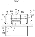
- FIG. 1 is an overall view of a rotary electric machine according to a first embodiment of the present invention.
- the rotary electric machine 1 includes a stator 20 and a rotor 30.
- the stator 20 is housed in the housing 12, the end brackets 11 are arranged at both ends of the housing 12, and support the shaft 70 via bearings 71.
- the rotor 30 is attached to the shaft 70.
- the rotor 30 is composed of a rotor core 300 and a magnet 4.
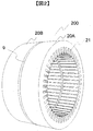
- FIG. 2 is a perspective view of a split core of the stator according to the first embodiment of the present invention.
- the stator 20 is divided in the axial direction, and the insulating member 5 is arranged on the abutting surface 9 of the core therebetween.
- the stator core 200 is provided with a slot 21 into which a coil is inserted, and is divided into two stator blocks 20A and 20B in the axial direction.
- the insulating member 5 is provided on the abutting surfaces 9 of the stator blocks 20A and 20B.
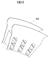
- FIG. 3 shows an insulating shape of the stator according to the first embodiment of the present invention.
- the integral molding is a method of molding the insulating member 5 by putting the stator core 200 in a mold which is slightly larger than the stator core 200 and has substantially the same shape, and injecting a thermoplastic resin into the gap.
- the stator block 20A or 20B can be provided with the insulating member 5 having the shape shown in FIG. If the insulating member 5 is applied to the core, the end face of the stator 20 and the inside of the slot 21 can be electrically insulated.
- the insulating member 5 is preferably thin, and preferably 1 mm or less.
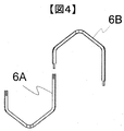
- FIG. 4 is a diagram showing a segment coil according to the first embodiment of the present invention.
- a segment coil 6A and a segment coil 6B molded in a U shape as shown in FIG. 4 are inserted into the stator blocks 20A and 20B from opposite sides in the axial direction, respectively.
- the tip of the segment coil 6A is processed into a concave shape
- the tip of the segment coil 6B is processed into a convex shape.
- the segment coil is inserted across the slots, and 4 to 10 coils are inserted in one slot.
- stator block 20A and the stator block 20B may be impregnated with varnish, for example, for the purpose of integrally fixing the iron core and the segment coil.
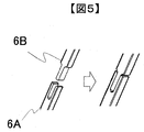
- FIG. 5 is a diagram showing a segment coil fitting method according to the first embodiment of the present invention. All the segment coils are fitted and electrically connected as shown in FIG. 5 in the vicinity of the abutting surfaces 9 of the stator block 20A and the stator block 20B.
- FIG. 6 is a diagram showing a method of connecting the stator according to the first embodiment of the present invention.
- the solid line shows the segment coil 6A on the front side of the paper
- the double line shows the segment coil 6B on the back side of the paper.
- the segment coil 6A is inserted into the stator block 20A from the front side of the drawing across the second layer of the first slot and the first layer of the fourth slot.
- the segment coil 6B inserted from the other side of the drawing is located in the fourth slot of the stator block 20B, and one ends of the segment coil 6A and the segment coil 6B are connected by fitting together with the abutment of the stator block.
- the other end of the segment coil 6B is inserted in the second layer of the 7th slot and connected to the coil of the next segment coil 6A.
- FIG. 7 is a diagram showing the structure of the split stator according to the first embodiment of the present invention.
- one end of the segment coil 6A has a length up to the vicinity of the abutting surface 9 of the stator block A, and the end portion thereof has a depth that can be visually confirmed from the lower side of the drawing.
- the coil 6B is inserted in the core block 20B, and the end portion of the segment coil 6B projects from the butt end surface of the stator block 20B.
- the abutting surfaces 9 of the stator blocks 20A and 20B are entirely covered with insulation. This is to secure an insulation creepage distance between the coil and the core on the split surface of the core.
- the reason why the creepage distance must be secured will be described with reference to FIG.
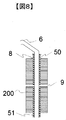
- FIG. 8 is a view showing the stator insulation of the conventional rotating electric machine.
- an insulating paper 51 is inserted into the slot of the stator core 200, and the segment coil 6 is housed in the insulating paper 51.
- the axial end face of the core and the segment coil 6 are insulated by the insulating paper 51.
- the dust 8 on the surface of the insulating material absorbs moisture due to moisture or the like, the insulation resistance may decrease.
- the surface of the material deteriorates due to local discharge, and finally a conductive path (track) is formed, which causes dielectric breakdown of the surface. This is called tracking.
- the insulating paper 51 is generally longer than the iron core 200 by about 5 mm as indicated by the insulating creepage distance 50. If this length is short, it will cause insulation deterioration due to tracking.
- the distance between the segment coil 6 of the enamel wire and the iron core 200 at the butted surface 9 of the core is only the thickness of the insulating paper 51.
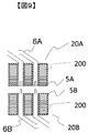
- the insulation paper is about 0.5 mm, and therefore the creepage distance cannot be secured. Therefore, in this embodiment, as shown in FIG. 9, in order to secure a creepage distance between the stator 200 and the segment coil 6, the surface of the core is also insulated.
- the creepage distance from the segment coil to the stator core can include the distance from the slot in the direction perpendicular to the axis that insulates the core surface. Therefore, it is possible to insulate the rotary electric machine in which the core, the coil, and the insulating member are divided in the axial direction.
- the core has an axial length of, for example, 150 mm or more, it is difficult to obtain the linear accuracy of the thin coil, and when the axial insertion into the slot of the stator, the insulating paper is often torn or misaligned. Therefore, there is a drawback that the motor manufacturing method becomes difficult. In this embodiment, since the insulating paper is not used, the manufacturability of the motor is improved.
- the insulating paper requires a creepage distance of about 5 mm between the core and the coil to prevent dielectric breakdown due to tracking, and the paper protrudes from the end face of the core by that amount.
- a margin was required for this straight line portion, and the coil end could not be shortened by that length.
- the surface of the core is also insulated, so that the creepage distance from the segment coil to the stator core is the direction perpendicular to the axis where the slot is insulated from the surface of the core. Since the distance can be included, the coil end can be shortened.
- the insulating member 5 is formed on the entire surface of the core end surface in this embodiment, the insulating member 5 on the core end surface is insulated within a certain distance in the direction perpendicular to the axis from the slot in consideration of the creepage distance. If so, the same effect can be obtained.
- the example in which the insulating member 5 is integrally formed in the stator end surface and the slot is shown, but if the creepage distances are secured separately in the core end surface and the slot, the stator end surface Even if the insulating member 5 and the insulating member 5 in the slot 21 are separate bodies, the same effect can be obtained.
- the protrusions 54 are made of integrally molded resin in the stator block 20A so that the stator blocks 20A are not displaced when they are stacked, and A recess may be formed to receive the protrusion 52.
- the stator block is stabilized after the blocks are abutted with each other, so that it is possible to prevent the core from being displaced and the coil connection from being divided.
- the coil is shortened and the coil can be easily inserted from the axial direction. Further, the positions of the coils of the respective stator blocks can be correctly aligned immediately before the blocks are brought into contact with each other, so that the fitting is less likely to fail. Further, since the core end face in the vicinity of the coil is insulated, the insulation creepage distance in the vicinity of the fitting portion can be secured and the insulation can be easily secured. Further, since the preformed segment coil is inserted into the core, there is no bending work after assembling and the segment coil can be inserted to the end surface of the core, and the coil end can be shortened.
- FIG. 13 is a view showing the structure of the split stator according to the second embodiment of the present invention.
- the difference from the first embodiment is that the core is divided into three or more instead of two.
- the segment coil 6A is formed by stacking a stator block 20A and a stator block 20B, or a larger number of stator blocks. In the abutting surface 9 near the fitting portion of the coil, the short portion of the segment coil 6B projects from the axial end surface of the stator block 20C.
- the stator block 20B is divided into two stator blocks.
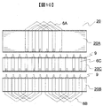
- a stator block 20C may be arranged between the stator blocks 20A and 20B.
- the butt surface 9 is provided at two places, and the segment coil 6C to be inserted into the stator 20C has a linear shape and has a fitting portion at both ends, but the stator can be assembled in the same manner.
- it may be configured to be fitted inside the stator 20C.
- the segment coil 6B and the segment coil 6C since there are two types of segment coils, the segment coil 6B and the segment coil 6C, it is possible to manufacture with only two types of segment coils. In this case, the same effect can be obtained even if the structure is fitted inside the stator block 20A.
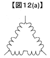
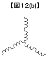
- FIGS. 12A, 12B and 12C are views showing a method of manufacturing a rotary electric machine according to the third embodiment of the present invention.
- the rotary electric machine can change the connection by changing the lead wire or the modified coil 63.
- FIGS. 12A, 12B and 12C show a delta connection
- FIG. 12B shows a star connection
- FIG. 12C shows a parallel connection.
Landscapes
- Engineering & Computer Science (AREA)
- Power Engineering (AREA)
- Manufacturing & Machinery (AREA)
- Insulation, Fastening Of Motor, Generator Windings (AREA)
- Iron Core Of Rotating Electric Machines (AREA)
- Windings For Motors And Generators (AREA)
- Manufacture Of Motors, Generators (AREA)
Abstract
コア内部でセグメントコイルを嵌合して固定子巻線を形成する方法において、内部が見えずに接続の可否が判定できない問題があった。またセグメントコイルが長いと、スロットに入りづらくスロット内の絶縁紙を破損する課題があった。また、コアを分割しているため、コアの分割部でコアとの絶縁が確保できない課題があった。 第1セグメントコイルを収納する第1スロットを有する第1固定子コアと、第2セグメントコイルを収納する第2スロットを有する第2固定子コアと、第1固定子コアと第2固定子コアとの間に配置される絶縁部材と、を備える回転電機の固定子であって、第1固定子コアの軸方向端面は、第2固定子コアの軸方向端面と対向し、第1セグメントコイルの端部は、第1固定子コア内に配置され、第2セグメントコイルの端部は、第2固定子コアの軸方向端面から突出する回転電機の固定子。
Description
本発明は回転電機の主に固定子とその製造方法に関する。
昨今の持続可能な社会の実現に向け、省エネルギーのため回転電機は小型・高効率化が求められており、特に自動車などの移動体向けの回転電機では、軽量・小型化が重要である。このような回転電機として、例えば、複数の永久磁石を備えた回転子と、この回転子と対向して設けられた固定子鉄心と、この固定子鉄心に巻掛けられた固定子巻線とを有する永久磁石を備えた回転電機において、モータの性能に寄与しないコイルエンド部が小さい小型の固定子とすることが必要である。この製造方法として、コイルの直線導体をスロットに配置した固定子コアモジュールと、コイルエンド部を絶縁部材モールド成形したモールドエンド部を接合した構造を有するものが提案されている(特許文献1)。
特許文献1の技術は、固定子コアは一つであり、そのコアの軸方向の外側でモールドエンドのコイルと嵌合している。特許文献1の図5のコイル形状から分かるように嵌合部は直線でなければならないため、この直線分だけコイルエンドが長くなってしまう。また、コアの軸方向両側でコイルが分割されているため、嵌合部が2箇所となり、コイルエンドはその分長くなる。
本発明は上記問題点に鑑みてなされたもので、本発明の課題は、接続信頼性を確保しながら小型化を図ることを目的とする。
上記課題を解決するために、本発明に係る回転電機の固定子は、第1セグメントコイルを収納する第1スロットを有する第1固定子コアと、第2セグメントコイルを収納する第2スロットを有する第2固定子コアと、第1固定子コアと第2固定子コアとの間に配置される絶縁部材と、を備える回転電機の固定子であって、第1固定子コアの軸方向端面は、第2固定子コアの軸方向端面と対向し、第1セグメントコイルの端部は、第1固定子コア内に配置され、第2セグメントコイルの端部は、第2固定子コアの軸方向端面から突出する。
本発明によれば、接続信頼性を確保しながら小型化を図る回転電機を提供することができる。
以下、本発明を実施するための例(以下においては「実施例」と表記する)を、図面を参照して説明する。なお、実施例を説明するための全図において、同一の部材には原則として同一の符号を付し、重複する説明は、適宜省略する。なお、本発明は、以下に説明する実施例に限定されるものではない。
実施形態を説明する前に、本発明に至った背景または原理について説明する。
昨今の持続可能な社会の実現に向け,省エネルギーのため回転電機は小型・高効率化が求められており,特に自動車などの移動体向けの回転電機では、軽量・小型化が重要である。このような回転電機として、例えば、複数の永久磁石を備えた回転子と、この回転子と対向して設けられた固定子鉄心と、この固定子鉄心に巻掛けられた固定子巻線とを有する永久磁石を備えた回転電機において、モータの性能に寄与しないコイルエンド部が小さい小型の固定子とすることが必要である。このような回転電機の固定子として,コイルの直線導体をスロットに配置した固定子コアモジュールと、コイルエンド部を絶縁体モールド成形したモールドエンド部を接合した構造を有するものが考えられる。しかし、このような構造では、嵌合部は直線でなければならないため、この直線分だけコイルエンドが長くなってしまう。また、スロット内でコイルを接続する方法も考えられるが、このようなコイル接続は,内部で嵌合がなされているかどうかを確認する方法がないため、組立性が悪化する。また、スロット内の銅線が太く電気抵抗の小さい固定子を作る方法として、セグメントコイルを用いた固定子が考えられる。しかし、コアがたとえば150mm以上の軸長があると、細いコイルの直線精度が出にくく、固定子のスロット内に軸方向から挿入する際、絶縁紙の破れやずれなどが多くなり、モータ製造方法が困難になる。
本実施形態は、上記問題点に鑑みてなされたものである。
[実施例1]
本実施例を図1、図2、図3を用いて説明する。図1は、本発明の第1の実施例に係る回転電機の全体図である。図1に示されるように、回転電機1は、固定子20と回転子30からなる。固定子20はハウジング12に納められ、ハウジング12の両端にエンドブラケット11が配置され、ベアリング71を介してシャフト70を支えている。シャフト70には回転子30が取り付けられる。回転子30は、回転子鉄心300と磁石4とで構成される。
本実施例を図1、図2、図3を用いて説明する。図1は、本発明の第1の実施例に係る回転電機の全体図である。図1に示されるように、回転電機1は、固定子20と回転子30からなる。固定子20はハウジング12に納められ、ハウジング12の両端にエンドブラケット11が配置され、ベアリング71を介してシャフト70を支えている。シャフト70には回転子30が取り付けられる。回転子30は、回転子鉄心300と磁石4とで構成される。
図2は、本発明の第1の実施例に係る固定子の分割鉄心の斜視図である。図2に示されるように、本実施例では、固定子20が軸方向に分割され、その間にコアの突き合わせ面9に絶縁部材5が配置される構造となっている。固定子鉄心200は、コイルが挿入されるスロット21が設けられており、軸方向に固定子ブロック20Aと20Bとに2分割されている。絶縁部材5が、固定子ブロック20A及び20Bの突き合わせ面9に施されている。
ここで、絶縁部材5を固定子ブロック20A及び20Bに施す方法として、たとえば粉体塗装や静電塗装がある。あるいは、樹脂をコアと一体成形してもよい。図3は、本発明の第1の実施例に係る固定子の絶縁形状である。一体成形は、固定子鉄心200より少し大きくほぼ同じ形状の型の中に固定子鉄心200を入れ、その隙間に熱可塑性樹脂を注入し、絶縁部材5を成型する方法である。これにより、固定子ブロック20A又は20Bに、図3に示されるような形状の絶縁部材5を施すことができる。絶縁部材5がコアに施されていれば、固定子20の端面とさらにスロット21内も電気的に絶縁することができる。絶縁部材5は薄いほうが望ましく、1mm以下が望ましい。
図4は、本発明の第1の実施例に係るセグメントコイルを示す図である。固定子ブロック20A、20Bには、それぞれ軸方向の反対側から図4に示されるようなU字型に成型されたセグメントコイル6A及びセグメントコイル6Bが挿入される。セグメントコイル6Aの先端は凹型に加工されており、セグメントコイル6Bの先端は凸型に加工されている。セグメントコイルはスロットを跨って挿入され、1つのスロットにはコイルが4から10本程度入る。例えば、図2の固定子鉄心の場合、スロット21は48個あり、ここにスロットあたり4本のセグメントコイル6Aが挿入されるとすると、セグメントコイル6Aと6Bの数はそれぞれ96ずつ必要となる。
固定子ブロック20Aと固定子ブロック20Bには、鉄心とセグメントコイルを一体化して固定する目的で、たとえばワニスを含浸させてもよい。
図5は、本発明の第1の実施例に係るセグメントコイルの嵌合方法を示す図である。すべてのセグメントコイルは、固定子ブロック20Aと固定子ブロック20Bの突き合わせ面9の近傍において、図5に示されるように嵌合され、電気的に接続される。
図6は、本発明の第1の実施例に係る固定子の結線方法を示す図である。図6では、3相モータの1相分のコイルだけを示す。図6中、実線は紙面手前のセグメントコイル6A、二重線は紙面奥のセグメントコイル6Bが示されている。たとえば、直列回路(1)は、セグメントコイル6Aが1番スロットの2層目と4番スロットの1層目に跨って紙面手前から固定子ブロック20A差し込まれる。固定子ブロック20Bの4番スロットには、紙面向こう側から差し込まれたセグメントコイル6Bが位置し、セグメントコイル6Aとセグメントコイル6Bの一端は、固定子ブロックの突合せとともに嵌合により接続される。セグメントコイル6Bの他端は、7番スロットの2層目に挿入され、次のセグメントコイル6Aのコイルと接続される。これを繰り返し固定子コアを1周することで、固定子コイルはいわゆる波巻きにより巻線が形成される。直列回路(2)から直列回路(4)も同様に巻線を形成し、4周分のコイルができる。それらを3相分作ることで固定子巻線が完成する。
図7は、本発明の第1の実施例に係る分割固定子の構造を示す図である。図7に示されるように、セグメントコイル6Aの一端は、固定子ブロックAの突合せ面9付近まで長さがあり、その終端部は紙面下方向から目視で確認できる程度の深さとする。コアブロック20Bには、コイル6Bが挿入されており、セグメントコイル6Bの端部は、固定子ブロック20Bの突合せ端面から突出している。このような構造にすることにより、セグメントコイル6Aと6Bとを嵌合する前に、互いのコイルの位置を詳細に測定し、嵌合の可否を予め判断することができる。また、コアを付き合わせた後には、コイルの接続部は固定されるため嵌合が外れることはない。これにより、より信頼性の高いモータを提供することができる。
本実施例において、固定子ブロック20Aと20Bの突合せ面9は全面的に絶縁で覆われている。これは、コアの分割面でコイルとコアの間の絶縁沿面距離を確保するためである。以下、図8を用いて、沿面距離を確保しなければならない理由を説明する。
図8は、従来の回転電機の固定子絶縁を示す図である。従来の回転電機では、固定子鉄心200のスロットには絶縁紙51を挿入し、その中にセグメントコイル6を収める構造となっている。この場合、コアの軸方向端面とセグメントコイル6とは、絶縁紙51により絶縁されている。しかし、絶縁材料の表面の塵埃8が湿気などによって吸湿することにより、絶縁抵抗が低下してしまうことがある。コイルからコアへ漏れ電流が流れる状態が続くと、局部的な放電により材料の表面が劣化し、最終的には導電路(トラック)ができ、表面の絶縁破壊が起きる。これをトラッキングという。このトラッキングを避けるため、絶縁紙51は鉄心200よりも絶縁沿面距離50で示すように5mm程度長くすることが一般的である。この長さが短いと、トラッキングによる絶縁劣化の原因となる。
分割した別々のコアを突き合わせて接続する工法だと、コアの突き合わせ面9の部分では、エナメル線のセグメントコイル6と鉄心200の間の距離は絶縁紙51の厚みしかない。通常、絶縁紙は0.5mm程度であるため、沿面距離を確保できない。そこで本実施例では、図9に示されるように、固定子200とセグメントコイル6の間の沿面距離を確保するため、コアの表面にも絶縁を施している。これにより、セグメントコイルから固定子コアまでの沿面距離は、スロットからコア表面に絶縁を施した軸に垂直な方向の距離も含めることができる。したがって、コアとコイルと絶縁部材を、軸方向に分割した回転電機の絶縁が可能になる。
以上より、本実施例では、内部で嵌合がなされているかどうかを確認することができるため、製造の不良率を下げることができる。また、従来のモータでは、コアがたとえば150mm以上の軸長があると、細いコイルの直線精度が出にくく、固定子のスロット内に軸方向から挿入する際、絶縁紙の破れやずれなどが多くなり、モータ製造方法が困難になる欠点があった。本実施例では、絶縁紙を用いないため、モータの製造性が向上する。また、従来のモータでは、絶縁紙はトラッキングによる絶縁破壊を防ぐためにコアとコイルの間に5mm程度の沿面距離が必要であり、その分、コア端面から紙がはみ出ている。このセグメントコイルを曲げる際に破れるのを避けるため、この直線部分にマージンが必要で、その長さ分コイルエンドが短くできなかった。本実施例で示される回転電機の固定子では、コアの表面にも絶縁を施すことにより、セグメントコイルから固定子コアまでの沿面距離は、スロットからコア表面に絶縁を施した軸に垂直な方向の距離も含めることができるため、コイルエンドを短くすることができる。
なお、本実施例では、絶縁部材5がコア端面全面に形成されている例を示したが、沿面距離の考えから、コア端面の絶縁部材5はスロットから軸に垂直方向に一定距離以内に絶縁されていれば、同じ効果が得られる。
また、本実施例では絶縁部材5が固定子端面とスロット内で一体に成型されている例を示したが、コア端面とスロット内に別々に沿面距離が確保されていれば、固定子端面の絶縁部材5とスロット21内の絶縁部材5が別体であっても、同様の効果が得られる。
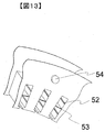
また、図13に示されるように分割した固定子ブロックを積重ねるときにずれないように、固定子ブロック20Aには一体成形の樹脂で突起54を作っておき、固定子ブロックBには、その突起52を受ける凹部をつくってもよい。このような構成とすることにより、ブロックを突き合わせた後に固定子ブロックが安定するので、コアがずれてコイル接続が分断するのを避けることができる。また、スロット内のコイルの位置決めが容易になるように、射出成形時にコイルのガイド52を作ること、または、隣のコイルとの接触を避けるために、コイル仕切り53をつくることもできる。これにより、簡易な方法で固定子を組み立てることができる。すなわち、コイルの嵌合部付近でコアとコイルを分割しているので、コイルが短くなりコイルを軸方向から挿入しやすくなる。また、ブロックをつき合わせる直前におのおの固定子ブロックの各コイルの位置を正しく揃えることができるので嵌合が失敗しにくくなる。また、コイルの近傍のコア端面を絶縁しているので、嵌合部付近の絶縁沿面距離を確保でき、絶縁性の確保も容易である。また、予め成形されたセグメントコイルをコアに挿入するので、組立て後の曲げ作業が無く、セグメントコイルをコアの端面まで差し込むことが可能となり、コイルエンドを短くすることができる。
[実施例2]
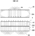
図10、図14及び図15を用いて、本発明の実施例2に係る固定子を説明する。図13は、本発明の第2の実施例係る分割固定子の構造を示す図である。実施例1との違いは、コアが2つではなく3つ以上に分割されていることである。セグメントコイル6Aは固定子ブロック20Aと固定子ブロック20B、あるいはそれ以上の数の固定子ブロックを積重ねている。そして、コイルの嵌合部付近の突き合わせ面9は、セグメントコイル6Bの短部が固定子ブロック20Cの軸方向端面から突出している。換言すると、固定子ブロック20Bを2つの固定子ブロックに分割している。これにより、積厚の違う回転電機を製造することができ、設備の共用化などが可能である。回転電機の製品としての効果は実施例1と同様の効果を得ることができる。
図10、図14及び図15を用いて、本発明の実施例2に係る固定子を説明する。図13は、本発明の第2の実施例係る分割固定子の構造を示す図である。実施例1との違いは、コアが2つではなく3つ以上に分割されていることである。セグメントコイル6Aは固定子ブロック20Aと固定子ブロック20B、あるいはそれ以上の数の固定子ブロックを積重ねている。そして、コイルの嵌合部付近の突き合わせ面9は、セグメントコイル6Bの短部が固定子ブロック20Cの軸方向端面から突出している。換言すると、固定子ブロック20Bを2つの固定子ブロックに分割している。これにより、積厚の違う回転電機を製造することができ、設備の共用化などが可能である。回転電機の製品としての効果は実施例1と同様の効果を得ることができる。
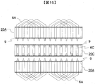
また、図10に示されるように、固定子ブロック20Aと20Bの間に、固定子ブロック20Cを配置してもよい。突き合わせ面9が2箇所になり、固定子20Cに挿入するセグメントコイル6Cは直線形状になり、両端に嵌合部がある構造となるが、同様に固定子を組み立てられる。また、図15に示されるように、固定子20Cの内部で嵌合する構成としてもよい。この場合、セグメントコイルは、セグメントコイル6B及びセグメントコイル6Cの2種類となるため、2種類のセグメントコイルだけで製造ができる。この場合、固定子ブロック20A内部で嵌合させる構造としても同様の効果が得られる。
[実施例3]
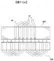
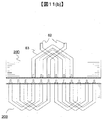
図11(a)及び(b)は、本発明の第3の実施例に係る回転電機の製造方法を示す図である。固定子ブロック20Bを共通に、固定子ブロック20Aと20Dを入れ替えることで、トルクや電圧仕様の異なる別の回転電機の固定子が製造できる。回転電機は、口出し線や異形コイル63を変えることで、結線を変えることができる。例えば、図12(a)、(b)及び(c)に示されるように、図12(a)はデルタ結線、図12(b)はスター結線、図12(c)は並列接続である。このような結線を変えることでモータの電圧・電流の仕様を変えることができる。また、軸方向の積厚を変えることで異なるトルク仕様のモータにすることができる。このような方法でより多くの多品種展開する回転電機を、少ない設備で作ることもできる。
図11(a)及び(b)は、本発明の第3の実施例に係る回転電機の製造方法を示す図である。固定子ブロック20Bを共通に、固定子ブロック20Aと20Dを入れ替えることで、トルクや電圧仕様の異なる別の回転電機の固定子が製造できる。回転電機は、口出し線や異形コイル63を変えることで、結線を変えることができる。例えば、図12(a)、(b)及び(c)に示されるように、図12(a)はデルタ結線、図12(b)はスター結線、図12(c)は並列接続である。このような結線を変えることでモータの電圧・電流の仕様を変えることができる。また、軸方向の積厚を変えることで異なるトルク仕様のモータにすることができる。このような方法でより多くの多品種展開する回転電機を、少ない設備で作ることもできる。
1…回転電機、4…磁石、5…絶縁部材、6…セグメントコイル、8…塵埃、9…コアの突き合わせ面、11…エンドブラケット、12…ハウジング、20…固定子、20A…固定子ブロックA、20B…固定子ブロックB、20C…固定子ブロックC、21…スロット、30…回転子、50…絶縁沿面距離、51…絶縁紙、52…コイルガイド、53…コイル仕切り、54…突起、61…亘り線、62…口出し線、63…異形コイル、70…シャフト、71…ベアリング、200…固定子鉄心、300…回転子鉄心
Claims (14)
- 第1セグメントコイルを収納する第1スロットを有する第1固定子コアと、
第2セグメントコイルを収納する第2スロットを有する第2固定子コアと、
前記第1固定子コアと第2固定子コアとの間に配置される絶縁部材と、を備える回転軸を有する回転電機の固定子であって、
前記第1固定子コアの前記回転軸方向端面は、前記第2固定子コアの前記軸方向端面と対向し、
前記第1セグメントコイルの端部は、前記第1固定子コア内に配置され、
前記第2セグメントコイルの端部は、前記第2固定子コアの軸方向端面から突出する回転電機の固定子。 - 請求項1に記載の回転電機の固定子であって、
前記第2固定子コアは、第3固定子コアと、当該第3固定子コアを介して前記第1コアの軸方向端面と対向する第4固定子コアとに分割され、
前記絶縁部材は、前記第3固定子コアと前記第4固定子コアとの間に配置される回転電機の固定子。 - 第1セグメントコイルを収納する第1スロットを有する第1固定子コアと、
第2セグメントコイルを収納する第2スロットを有する第2固定子コアと、
第3セグメントコイルを収納する第3スロットを有し、前記第1固定子コアと前記第3固定子コアの間に配置される第3固定子コアと、
前記第1固定子コア及び前記第3固定子コア間並びに前記第2固定子コア及び前記第3固定子コア間に配置される絶縁部材と、を備える回転軸を有する回転電機の固定子であって、
前記回転軸の軸方向における前記第1固定子コアの端面は、前記第2固定子コア及び前記第3固定子コアの軸方向端面と対向し、
前記第1セグメントコイルの端部は、前記第1固定子コア又は前記第3固定子コア内で前記第3セグメントコイルの一端と接続し、
前記第2セグメントコイルの端部は、前記第2固定子コア又は前記第3固定子コア内で前記第3セグメントコイルの他端と接続する回転電機の固定子。 - 請求項1乃至3のいずれか1つに記載の回転電機の固定子であって、
前記絶縁部材は、前記第1固定子コアと前記第2固定子コアの軸方向における端面の両面に配置される回転電機の固定子。 - 請求項1乃至4のいずれか1つに記載の回転電機の固定子であって、
前記絶縁部材は、前記第1固定子コア又は前記第2固定子コアの軸方向端面を覆うように形成される回転電機の固定子。 - 請求項1乃至5のいずれか1つに記載の回転電機の固定子であって、
前記絶縁部材は、前記第1スロットまたは前記第2スロットを形成する面に沿って形成されるスロット絶縁部を有する回転電機の固定子。 - 請求項6に記載の回転電機の固定子であって、
前記絶縁部材は、前記第1固定子コアの端面に接する部分とスロット絶縁部とが一体的に形成される回転電機の固定子。 - 請求項6又は7に記載の回転電機の固定子であって、
前記絶縁部材は、前記スロット絶縁部のうち径方向に沿った面に前記第1セグメントコイルをガイドするためのガイド部を有し、
前記ガイド部は、周方向へ突出する回転電機の固定子。 - 請求項6乃至8のいずれか1つに記載の回転電機の固定子であって、
前記絶縁部材は、前記スロット絶縁部のうち径方向に沿った面に前記第1セグメントコイル又は前記第2セグメントコイルと、他のセグメントコイルと、を仕切るための仕切り部を有する回転電機の固定子。 - 請求項1乃至8のいずれか1つに記載の回転電機の固定子であって、
前記絶縁部材は、前記第1固定子コアの端面上に形成される第1絶縁部材と、当該第1絶縁部材と対向する第2絶縁部材と、により構成され、
前記第1絶縁部材及び前記第2絶縁部材は、互いに嵌合するための嵌合部を有する回転電機の固定子。 - 請求項1乃至10のいずれか1つに記載の回転電機の固定子であって、
前記絶縁部材は、粉体塗装あるいは静電塗装によってコアに塗布される回転電機の固定子。 - 請求項1乃至11のいずれか1つに記載の回転電機の固定子と、
回転子と、を備える回転電機。 - 第1固定子コアの軸方向端面の一部に絶縁部材を形成し、他面から第1セグメントコイルを挿入して第1のコアブロックを形成する第1工程と、
第1固定子コアの軸方向端面の一部に絶縁部材を形成し、他面から第2セグメントコイルを挿入して第2のコアブロックを形成する第2工程と、
前記第1の固定子ブロックと前記第2の固定子ブロックの絶縁部材が形成されている端面同士を突合せ、前記第1のセグメントコイルと前記第2のセグメントコイルを嵌合する第3工程と、を有する回転電機の固定子の製造方法。 - 第1固定子コアの軸方向端面の一部に絶縁部材を形成し、他面から第1セグメントコイルを挿入して第1のコアブロックを形成する第1工程と、
第1固定子コアの軸方向端面の一部に絶縁部材を形成し、他面から第2セグメントコイルを挿入して第2のコアブロックを形成する第2工程と、
第3固定子コアの軸方向の面の一部に絶縁部材を形成し、直線形状の第3のセグメントコイルを挿入して第3のコアブロックを形成し、
前記第1の固定子ブロックの絶縁部材が形成されている端面と前記第3の固定子ブロックの端面を突合せ、前記第1のセグメントコイルと前記第3のセグメントコイルを嵌合する第3工程と、
前記第2の固定子ブロックの絶縁部材が形成されている端面と前記第3の固定子ブロックの端面を突合せ、前記第2のセグメントコイルと前記第3のセグメントコイルを嵌合する第4工程と、を有する回転電機の固定子の製造方法。
Applications Claiming Priority (2)
| Application Number | Priority Date | Filing Date | Title |
|---|---|---|---|
| JP2018226211A JP7329918B2 (ja) | 2018-12-03 | 2018-12-03 | 回転電機の固定子および回転電機の固定子の製造方法 |
| JP2018-226211 | 2018-12-03 |
Publications (1)
| Publication Number | Publication Date |
|---|---|
| WO2020116157A1 true WO2020116157A1 (ja) | 2020-06-11 |
Family
ID=70975442
Family Applications (1)
| Application Number | Title | Priority Date | Filing Date |
|---|---|---|---|
| PCT/JP2019/045359 Ceased WO2020116157A1 (ja) | 2018-12-03 | 2019-11-20 | 回転電機の固定子および回転電機の固定子の製造方法 |
Country Status (2)
| Country | Link |
|---|---|
| JP (1) | JP7329918B2 (ja) |
| WO (1) | WO2020116157A1 (ja) |
Cited By (3)
| Publication number | Priority date | Publication date | Assignee | Title |
|---|---|---|---|---|
| CN116633104A (zh) * | 2022-02-21 | 2023-08-22 | 丰田自动车株式会社 | 定子的制造方法 |
| JP2024149938A (ja) * | 2023-04-10 | 2024-10-23 | 日立Astemo株式会社 | 回転電機 |
| WO2025163725A1 (ja) * | 2024-01-30 | 2025-08-07 | Astemo株式会社 | 回転電機及びその固定子 |
Families Citing this family (4)
| Publication number | Priority date | Publication date | Assignee | Title |
|---|---|---|---|---|
| JP7331670B2 (ja) * | 2019-12-06 | 2023-08-23 | 日産自動車株式会社 | 回転電機のステータ、及び回転電機のステータの製造方法 |
| CN115515901B (zh) | 2020-05-27 | 2024-10-29 | 松下知识产权经营株式会社 | 无机结构体及其制造方法 |
| CN113113997A (zh) * | 2021-04-01 | 2021-07-13 | 贵州航天林泉电机有限公司 | 一种电机定子绝缘及绕组连接结构 |
| CN114069908A (zh) * | 2021-12-08 | 2022-02-18 | 安徽美芝精密制造有限公司 | 定子、电机、压缩机和电器设备 |
Citations (5)
| Publication number | Priority date | Publication date | Assignee | Title |
|---|---|---|---|---|
| JP2005312219A (ja) * | 2004-04-22 | 2005-11-04 | Minebea Co Ltd | 三層絶縁塗膜構造を有するモータコア及びその製造方法 |
| JP2006158044A (ja) * | 2004-11-26 | 2006-06-15 | Toyota Motor Corp | ステータ構造 |
| JP2007336650A (ja) * | 2006-06-13 | 2007-12-27 | Toyota Motor Corp | 回転電機の固定子 |
| JP2013208038A (ja) * | 2012-03-29 | 2013-10-07 | Honda Motor Co Ltd | 回転電機及び巻線装着方法 |
| JP2017163675A (ja) * | 2016-03-09 | 2017-09-14 | 三菱電機株式会社 | 固定子鉄心、固定子及び回転電機 |
-
2018
- 2018-12-03 JP JP2018226211A patent/JP7329918B2/ja active Active
-
2019
- 2019-11-20 WO PCT/JP2019/045359 patent/WO2020116157A1/ja not_active Ceased
Patent Citations (5)
| Publication number | Priority date | Publication date | Assignee | Title |
|---|---|---|---|---|
| JP2005312219A (ja) * | 2004-04-22 | 2005-11-04 | Minebea Co Ltd | 三層絶縁塗膜構造を有するモータコア及びその製造方法 |
| JP2006158044A (ja) * | 2004-11-26 | 2006-06-15 | Toyota Motor Corp | ステータ構造 |
| JP2007336650A (ja) * | 2006-06-13 | 2007-12-27 | Toyota Motor Corp | 回転電機の固定子 |
| JP2013208038A (ja) * | 2012-03-29 | 2013-10-07 | Honda Motor Co Ltd | 回転電機及び巻線装着方法 |
| JP2017163675A (ja) * | 2016-03-09 | 2017-09-14 | 三菱電機株式会社 | 固定子鉄心、固定子及び回転電機 |
Cited By (4)
| Publication number | Priority date | Publication date | Assignee | Title |
|---|---|---|---|---|
| CN116633104A (zh) * | 2022-02-21 | 2023-08-22 | 丰田自动车株式会社 | 定子的制造方法 |
| JP2024149938A (ja) * | 2023-04-10 | 2024-10-23 | 日立Astemo株式会社 | 回転電機 |
| US12549043B2 (en) * | 2023-04-10 | 2026-02-10 | Hitachi Astemo, Ltd. | Rotating electric machine |
| WO2025163725A1 (ja) * | 2024-01-30 | 2025-08-07 | Astemo株式会社 | 回転電機及びその固定子 |
Also Published As
| Publication number | Publication date |
|---|---|
| JP7329918B2 (ja) | 2023-08-21 |
| JP2020092468A (ja) | 2020-06-11 |
Similar Documents
| Publication | Publication Date | Title |
|---|---|---|
| JP7329918B2 (ja) | 回転電機の固定子および回転電機の固定子の製造方法 | |
| CN113258704B (zh) | 线圈骨架、定子铁芯及分布绕组径向间隙型旋转电机 | |
| JP5314908B2 (ja) | 回転電機の固定子および回転電機 | |
| CN101873023A (zh) | 电枢 | |
| CN111245164B (zh) | 旋转电机及其制造方法 | |
| US12095322B2 (en) | Stator | |
| JP2003259571A (ja) | 回転電機 | |
| US11336133B2 (en) | Stator for an electric motor | |
| US11239719B2 (en) | Transducer for converting between electrical energy and mechanical energy | |
| US11329526B2 (en) | Stator, stator assembly, and transducer for converting between electrical energy and mechanical energy | |
| GB2503500A (en) | An armature connecting wire arrangment for an electric motor | |
| JP7280706B2 (ja) | 回転電機の固定子及びそれを用いた回転電機 | |
| US20250309719A1 (en) | Coil assembly, armature and rotating electric machine | |
| JP7254140B1 (ja) | 回転電機 | |
| JP7543156B2 (ja) | 回転電機 | |
| JP2023122730A (ja) | コアユニット、コアユニット組立体および回転電機 | |
| JP2017163675A (ja) | 固定子鉄心、固定子及び回転電機 | |
| JP7205454B2 (ja) | ステータ、ステータアッセンブリ、電気エネルギーと力学的エネルギーとの変換器 | |
| WO2015040692A1 (ja) | 回転電機の固定子 | |
| JP7188370B2 (ja) | 電気エネルギーと力学的エネルギーとの変換器 | |
| KR20230071546A (ko) | 모터 | |
| US20260142517A1 (en) | Stator of rotating electric machine and method for manufacturing same | |
| JP7671941B2 (ja) | コイル及びそれを備えたステータ、モータ | |
| JP7205453B2 (ja) | ステータ、ステータアッセンブリ、電気エネルギーと力学的エネルギーとの変換器 | |
| WO2025164043A1 (ja) | 回転電機及び回転電機の製造方法 |
Legal Events
| Date | Code | Title | Description |
|---|---|---|---|
| 121 | Ep: the epo has been informed by wipo that ep was designated in this application |
Ref document number: 19894046 Country of ref document: EP Kind code of ref document: A1 |
|
| NENP | Non-entry into the national phase |
Ref country code: DE |
|
| 122 | Ep: pct application non-entry in european phase |
Ref document number: 19894046 Country of ref document: EP Kind code of ref document: A1 |