WO2020116124A1 - 超音波信号処理装置、超音波診断装置、および、超音波信号処理方法 - Google Patents
超音波信号処理装置、超音波診断装置、および、超音波信号処理方法 Download PDFInfo
- Publication number
- WO2020116124A1 WO2020116124A1 PCT/JP2019/044808 JP2019044808W WO2020116124A1 WO 2020116124 A1 WO2020116124 A1 WO 2020116124A1 JP 2019044808 W JP2019044808 W JP 2019044808W WO 2020116124 A1 WO2020116124 A1 WO 2020116124A1
- Authority
- WO
- WIPO (PCT)
- Prior art keywords
- region
- ultrasonic
- target
- unit
- wave
- Prior art date
- Legal status (The legal status is an assumption and is not a legal conclusion. Google has not performed a legal analysis and makes no representation as to the accuracy of the status listed.)
- Ceased
Links
Images





Classifications
-
- A—HUMAN NECESSITIES
- A61—MEDICAL OR VETERINARY SCIENCE; HYGIENE
- A61B—DIAGNOSIS; SURGERY; IDENTIFICATION
- A61B8/00—Diagnosis using ultrasonic, sonic or infrasonic waves
- A61B8/08—Clinical applications
Definitions
- the present disclosure relates to an ultrasonic diagnostic apparatus and an ultrasonic signal processing method, and more particularly, to analysis of shear wave propagation in tissue using shear waves and evaluation of mechanical properties of tissue.
- the ultrasonic diagnostic apparatus transmits ultrasonic waves from the plurality of transducers constituting the ultrasonic probe to the inside of the subject, receives ultrasonic reflected waves (echo) generated by the difference in acoustic impedance of the subject tissue, and obtains them.
- the medical inspection apparatus generates and displays an ultrasonic tomographic image showing the structure of the internal tissue of the subject based on the electric signal.
- SWSM Shear Wave Speed Measurement
- a region of interest ROI: Region of Interest
- a push wave focused ultrasound, or , ARFI: Acoustic Radiation Force Impulse
- ultrasonic waves for detection hereinafter referred to as “detection wave”
- the propagation velocity of shear waves representing the mechanical characteristics of the tissue can be calculated, and a map of the mechanical characteristics of the tissue represented by, for example, an elasticity image can be displayed ( For example, Patent Document 1).
- a typical method for shear wave propagation analysis is to detect displacements in a direction orthogonal to the shear wave propagation direction at a plurality of positions in the subject, and to measure the displacement of the displacement peak position in time series.
- the signal quality of the acoustic line signal based on the reflected ultrasonic waves of the detected wave varies depending on the position within the subject, and the use of the acoustic line signal of low signal quality has a problem that the displacement detection accuracy is affected.
- the present disclosure has been made in view of the above problems, and in shear wave velocity measurement, by improving the detection accuracy of the displacement amount, it is intended to improve the reliability of the mechanical properties of the obtained tissue To do.
- An ultrasonic signal processing device that transmits a push wave for generating a displacement in a subject to an ultrasonic probe, and following the transmission of the push wave, the subject
- An ultrasonic wave transmitting unit for transmitting a detection wave passing through a region of interest showing an analysis target range to the ultrasonic probe; and an ultrasonic wave reflected from the region of interest corresponding to the detection wave using the ultrasonic probe.
- a detection wave receiving unit that receives a sound wave and converts it into a reception signal, a phasing addition unit that performs phasing addition for each of a plurality of positions in the region of interest to generate an acoustic line signal, and a plurality of units in the region of interest.
- the target group setting unit that extracts a plurality of target regions consisting of observation points where the signal quality of the corresponding acoustic line signal is relatively high and sets the target group including the plurality of target regions as the target of the propagation analysis.
- a mechanical characteristic calculation unit that calculates mechanical characteristics of the subject in the region of interest based on acoustic line signals corresponding to each of a plurality of observation points included in the target group.
- the mechanical of the subject is measured based on the acoustic line signal acquired from the observation point set based on the quality of the acoustic line signal in the region of interest.
- the characteristics are calculated. Therefore, the reliability of the elastic modulus measurement result can be improved by improving the detection accuracy of the displacement amount.
- FIG. 3 is a schematic diagram showing an outline of a SWS sequence by a shear wave velocity measuring method in the ultrasonic diagnostic apparatus 100 according to the embodiment.
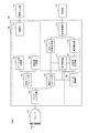
- 3 is a functional block diagram of an ultrasonic diagnostic system 1000 including the ultrasonic diagnostic apparatus 100.
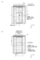
- FIG. (A) is a schematic diagram showing the position of the transmission focus F of the push wave generated by the push wave generation unit 103
- (b) is a schematic diagram showing an example of the configuration outline of the detection wave pulse generated by the detection wave generation unit 104. It is a figure.
- (A) is a functional block diagram showing a configuration of a transmission beamformer unit 105
- (b) is a functional block diagram showing a configuration of a reception beamformer unit 107.
- (A) is a schematic diagram showing an outline of detection wave transmission
- (b) is a schematic diagram showing an outline of reflection detection wave reception
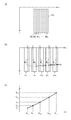
- (A) is a schematic diagram showing an outline of the target line candidate region Bnp in the partial region Srn
- (b) is a schematic diagram showing an outline of the target group Bx
- (c) is an outline of shear wave velocity detection.
- It is a schematic diagram which shows. 6 is a flowchart showing an operation of ultrasonic elastic modulus calculation in the ultrasonic diagnostic apparatus 100.
- 7 is a flowchart showing a setting operation of the target group Bx in the ultrasonic diagnostic apparatus 100. All of (a) to (c) are examples of elasticity images in the ultrasonic diagnostic apparatus 100.
- shear wave velocity measurement mechanical properties are evaluated by exciting shear waves in the subject by push waves and measuring the propagation state of shear waves. This is because, for example, the elastic modulus (Young's modulus) of the tissue is approximately proportional to the square of the propagation velocity of the shear wave. Therefore, in shear wave velocity measurement, the displacement of the inside of the subject is detected by repeatedly transmitting and receiving the detection wave after transmitting the push wave, and the position of the wave front of the shear wave is analyzed by analyzing the time series change. To estimate. Then, the mechanical characteristics are evaluated using the moving speed of the wavefront as the moving speed of the shear wave.
- FIG. 11A is a schematic diagram showing an example of the operation of estimating the position of the wavefront of the shear wave. Since the shear wave propagates from the focus FP of the push wave in a direction substantially orthogonal to the depth direction, the observation point P11 on the linear region L1, the observation point P21 on the linear region L2, and the linear region L3. The observation point P31 and the observation point P41 on the linear region L4 are passed in this order.
- the linear regions L1, L2, L3, and L4 are linear regions that extend in the depth direction y, and are arranged at a predetermined interval ⁇ x in the x direction.
- the predetermined interval ⁇ x is set in consideration of the transmission/reception interval of the detected wave and the estimated velocity of the shear wave so as not to be excessively narrowed.
- the peak times at the observation points P11, P21, P31, and P41 are calculated, and it is considered that the observation points have passed the wavefront of the shear wave at the peak time. With such processing, for example, the propagation analysis as shown in the schematic view of FIG. 11B becomes possible. In the schematic diagram of FIG.
- the propagation path of the shear wave is the d-axis
- the horizontal axis is the peak time
- the peak time is the vertical axis.
- the detection accuracy of the displacement amount is the magnitude of the displacement at the observation point and the signal quality of the reflection detection wave from the observation point, that is, the magnitude (amplitude) of the reflection detection wave and the signal-to-noise ratio (SNR).
- SNR signal-to-noise ratio
- the present invention has arrived at the ultrasonic signal processing device, the ultrasonic diagnostic device, and the ultrasonic signal processing method according to the present disclosure.
- the ultrasonic diagnostic apparatus 100 performs a process of calculating the propagation velocity of a shear wave that represents the elastic modulus of the tissue by the shear wave velocity measuring method.
- FIG. 1 is a schematic diagram showing an outline of the SWS sequence by the shear wave velocity measuring method in the ultrasonic diagnostic apparatus 100.
- the processing of the ultrasonic diagnostic apparatus 100 is composed of steps of “reference detection wave pulse transmission/reception”, “push wave pulse transmission/reception”, “detection wave pulse transmission/reception”, and “elastic modulus calculation”. To be done.
- the reference detection wave pulse pwp0 is transmitted to the ultrasonic probe, and the detection wave pw0 and the reflected wave are transmitted to a plurality of transducers in a range corresponding to the region of interest roi in the subject. ec is received to generate an acoustic ray signal that serves as a reference for the initial position of the tissue.
- the push wave pulse ppp is transmitted to the ultrasonic probe, and the plurality of transducers are caused to transmit the push wave pp in which the ultrasonic wave is converged to a specific portion in the subject, and A shear wave is excited in the sample tissue.
- the detection wave pulse pwpl is transmitted to the ultrasonic probe, and the plurality of transducers perform the transmission of the detection wave pwl and the reception of the reflected wave ec a plurality of times, whereby shearing is performed. Measure the propagation state of waves.
- the step of “elastic modulus calculation” first, the displacement distribution pt1 of the tissue accompanying the propagation of the shear wave is calculated in time series, and then the shear wave representing the elastic modulus of the tissue is calculated from the time series change of the displacement distribution pt1. Shear wave propagation analysis is performed to calculate the propagation velocity of, and finally the elastic modulus distribution is imaged and displayed as an elastic image.
- the elastic modulus calculation step is used here, the mechanical characteristic to be evaluated is not limited to the elastic modulus, and any mechanical characteristic that can be calculated from the shear wave velocity may be evaluated.
- SWS sequence The series of steps that accompanies the excitation of one shear wave based on push wave pp transmission shown above is called a "SWS sequence" (SWS: Shear Wave Speed).
- FIG. 2 is a functional block diagram of the ultrasonic diagnostic system 1000 according to the embodiment.
- the ultrasonic diagnostic system 1000 is an ultrasonic diagnostic system in which a plurality of transducers (transducer rows) 101a that transmit ultrasonic waves toward a subject and receive the reflected waves are arranged on the tip surface.
- An ultrasonic probe 101 (hereinafter, referred to as "probe 101"), an ultrasonic diagnostic apparatus 100 that causes the probe 101 to transmit and receive ultrasonic waves and generate an ultrasonic signal based on an output signal from the probe 101, an operation input from an inspector It has an operation input unit 102 for receiving the information and a display unit 115 for displaying an ultrasonic image on the screen.
- the probe 101, the operation input unit 102, and the display unit 115 are respectively configured to be connectable to the ultrasonic diagnostic apparatus 100.
- the probe 101 has a transducer row (101a) including a plurality of transducers 101a arranged in, for example, a one-dimensional direction (hereinafter, referred to as “transducer row direction”).
- the probe 101 converts a pulsed electric signal (hereinafter, referred to as a “transmission signal”) supplied from a transmission beamformer unit 105 described later into a pulsed ultrasonic wave.
- the probe 101 is a measurement target of an ultrasonic beam composed of a plurality of ultrasonic waves emitted from a plurality of transducers in a state where the outer surface of the probe 101 on the transducer side is applied to the skin surface of a subject through an ultrasonic gel or the like. To send to.
- the probe 101 receives a plurality of reflected detection waves (hereinafter referred to as “reflected waves”) from the subject, converts the reflected waves into electric signals by the plurality of transducers 101a, and then the ultrasonic diagnostic apparatus. Supply to 100.
- reflected waves a plurality of reflected detection waves
- Operation input unit 102 receives various operation inputs such as various settings and operations to the ultrasonic diagnostic apparatus 100 from the inspector, and outputs them to the control unit 114 of the ultrasonic diagnostic apparatus 100.
- the operation input unit 102 may be, for example, a touch panel integrally configured with the display unit 115. In this case, various settings and operations of the ultrasonic diagnostic apparatus 100 can be performed by performing a touch operation or a drag operation on the operation keys displayed on the display unit 115, and the ultrasonic diagnostic apparatus 100 is operated by the touch panel. Configured to be possible.
- the operation input unit 102 may be, for example, a keyboard having keys for various operations, an operation panel having buttons for various operations, a mouse, or the like.
- the display unit 115 is a display device for so-called image display, and displays an image output from the display control unit 113 described later on the screen.
- a liquid crystal display, a CRT, an organic EL display, or the like can be used as the display unit 115.
- the ultrasonic diagnostic apparatus 100 selects a transducer used for transmission or reception from among the plurality of transducers 101a of the probe 101, and a multiplexer unit 106 that secures input and output to the selected transducer, an ultrasonic wave.
- Transmission beam former unit 105 for controlling the timing of high voltage application to each transducer 101a of the probe 101 in order to perform transmission, and reception beamforming is performed based on the reflected wave received by the probe 101 to generate an acoustic line signal.
- the reception beamformer unit 107 is included.
- a push wave generation unit 103 for transmitting a push wave pulse ppp to a plurality of transducers 101a, and a detection wave generation unit 104 for transmitting a detection wave pulse pwpl a plurality of (m) times following the push wave pulse ppp.
- a data storage unit 108 that stores the acoustic ray signal output by the reception beamformer unit 107, a motion detection unit 111 that detects relative movement between the subject and the probe 101 from the acoustic ray signal, and a B-mode image from the acoustic ray signal.
- a B-mode image generation unit 112 to generate, a target group setting unit 109 that sets a target group of shear wave propagation analysis based on the signal quality of the acoustic line signal, a velocity calculation unit 110 that performs shear wave propagation analysis, and a B-mode image.
- a display control unit 113 that forms a display image from the propagation analysis result and displays it on the display unit 115, and further sets a region of interest roi that represents an analysis target range in the subject based on an operation input from the operation input unit 102.
- a control unit 114 for controlling each component is provided.
- the multiplexer unit 106, the transmission beam former unit 105, the reception beam former unit 107, the push wave generation unit 103, the detection wave generation unit 104, the target group setting unit 109, the speed calculation unit 110, and the control unit 114 are ultrasonic signals.
- the processing circuit 150 is configured.
- Each element constituting the ultrasonic signal processing circuit 150, the motion detection unit 111, the B-mode image generation unit 112, and the display control unit 113 are, for example, FPGA (Field Programmable Gate Array), ASIC (Application Specific Integrated Circuit), and the like. It is realized by the hardware circuit of. Alternatively, the configuration may be realized by a processor and software such as a CPU (Central Processing Unit) and a GPU (Graphics Processing Unit). In particular, a configuration using the GPU is a GPGPU (General-Purpose computing on Graphics Processing Unit). be called.
- These constituent elements can be one circuit component or can be an assembly of a plurality of circuit components. Further, a plurality of constituent elements can be combined into one circuit component, or a plurality of circuit components can be assembled.
- the data storage unit 108 is a computer-readable recording medium, and for example, a flexible disk, hard disk, MO, DVD, BD, semiconductor memory or the like can be used.
- the data storage unit 108 may be a storage device externally connected to the ultrasonic diagnostic apparatus 100.
- the ultrasonic diagnostic apparatus 100 is not limited to the ultrasonic diagnostic apparatus having the configuration shown in FIG.
- the multiplexer 106 may be unnecessary, or the probe 101 may include the transmission beam former 105, the reception beam former 107, or a part thereof.
- Control unit 114 Generally, in a state where a B-mode image that is a tomographic image of a subject acquired in real time by the probe 101 is displayed on the display unit 115, the operator uses the B-mode image displayed on the display unit 115 as an index. , The analysis target range in the subject is specified and input to the operation input unit 102. The control unit 114 sets the information designated by the operator from the operation input unit 102 as an input. At this time, the control unit 114 may set the region of interest roi, which represents the analysis target range in the subject, on the basis of the position of the transducer array (101a) including the plurality of transducers 101a in the probe 101. For example, the region of interest roi may be all or a part of the detection wave irradiation region Ax including the transducer row (101a) including the plurality of transducers 101a.
- the control unit 114 also controls other blocks of the ultrasonic diagnostic apparatus 100, which will be described later, based on a command from the operation input unit 102.
- the push wave generation unit 103 based on the information indicating the region of interest roi, the position of the transmission focus FP of the push wave and the transducer row that transmits the push wave ppp (hereinafter, “push wave transmission transducer row Px”). )) is determined as shown below.
- FIG. 3A is a schematic diagram showing the position of the transmission focus FP of the push wave ppp generated by the push wave generation unit 103.
- the length w of the region of interest roi in the column direction and the length h in the depth direction of the subject are equal to or less than the length a in the column direction and the length b in the depth direction of the subject, respectively, of the ultrasonic wave irradiation range of the plane wave.
- the case where the region of interest roi is set near the center of the irradiation range will be described as an example.
- the column-direction transmission focal position fx of the transmission focal point FP coincides with the column-direction center position wc of the region of interest roi.
- the push wave transmission transducer array Px is set based on the depth direction transmission focus position fy.
- the length of the push wave pulse transmission transducer array Px is set to the length a of all the transducers 101a.
- Information indicating the position of the transmission focus FP and the push wave transmission transducer array Px is output to the transmission beamformer unit 105 as a transmission control signal together with the pulse width PW of the push pulse ppp and the application start time PT. Further, the time interval PI of the application start time PT may be included. The pulse width PW of the push wave pulse ppp, the application start time PT, and the time interval PI will be described later.
- the positional relationship between the region of interest roi and the transmission focal point FP is not limited to the above, and may be changed as appropriate according to the form of the site to be examined of the subject.
- the column-direction transmission focus position fx of the transmission focus FP is offset from the column-direction center position wc of the region of interest roi in the positive or negative x-axis direction. You may change it. In this case, the region of interest width w and the center of the transducer array in the column direction are different. Further, the column-direction focal position fx of the transmission focus FP may be offset from the column-direction center wc of the region of interest roi in the positive or negative direction of the x-axis and located outside the region of interest roi.
- the transmission focus FP may be set at a predetermined position near the ROI and outside the ROI. At this time, when the transmission focus FP is set in the vicinity of the region of interest roi, the transmission focus FP is set at a distance with which the shear wave can reach the region of interest roi.
- the ultrasonic beam by the push wave is “focused”, it means that the ultrasonic beam is focused and is a focus beam, that is, the area irradiated to the ultrasonic beam decreases after transmission and the minimum value is reached at a specific depth. This means not only when the ultrasonic beam is focused on one point.
- the "transmission focus FP" refers to the center of the ultrasonic beam at the depth at which the ultrasonic beam is focused.
- Detection wave generation unit 104 The detection wave generation unit 104 inputs information indicating the region of interest roi from the control unit 114 and causes the plurality of transducers 101a to transmit the detection wave pulse pwpl from the transmission beam former unit 105 a plurality of times so that the ultrasonic beam has a region of interest.
- the detection wave pw is transmitted to the plurality of transducers 101a belonging to the detection wave pulse transmission transducer array Tx so as to pass through roi.
- the detection wave generation unit 104 transmits a detection wave pulse pwpl based on the information indicating the region of interest roi so that the ultrasonic beam passes through the region of interest roi.
- the transducer array Tx is determined.
- the number of times (m) the detection wave pulse pwpl is transmitted may be 30 to 100, for example.
- the transmission interval of the detection wave pulse pwpl may be, for example, 100 ⁇ sec to 150 ⁇ sec.
- these application conditions are not limited to the above and can be changed as appropriate.
- FIG. 5A is a schematic diagram showing a configuration outline of the detection wave pulse pwpl generated in the detection wave generation unit 104.
- the detection wave generation unit 104 transmits a transmission wave pulse to each of partial regions Sr1, Sr2,...
- the transmission transducer array Tx is set.
- the detection wave pulse is transmitted so that the detection wave converges at the center F1 of the partial region Sr1, and after the reflected ultrasonic wave is received, the detection wave is detected so as to converge at the center F2 of the partial region Sr2.
- Wave pulses are transmitted and reflected ultrasonic waves are received.
- the detection wave is transmitted/received while shifting the focus of the detection wave pulse to F3, F4,...
- the transmission/reception of the detection wave with the focus of the detection wave pulse being F6 completes the transmission/reception of one frame.
- the focus of the detection wave pulse is set to F1 again, and the detection wave pulse is transmitted and received.
- the method of transmitting and receiving the detection wave is not limited to the above case, and for example, the detection wave that is a plane wave may be transmitted so as to pass through the entire region of interest roi.
- the detection wave pulse transmission oscillator array Tx is set.
- the length a of the detection wave pulse transmission transducer array Tx is preferably set larger than the region of interest width w.
- the region of interest width w is set so as to be located inside by a predetermined distance ⁇ from the end of the detection wave pulse transmission transducer array Tx in the row direction. Since the detection wave pw is a plane wave, it propagates in the Y direction perpendicular to the transducer array direction. Therefore, the region of interest roi is included in the ultrasonic wave irradiation region Ax with a margin of the distance ⁇ at both ends in the X direction. Further, the detection wave pulse transmission transducer array Tx may be configured to include all of the plurality of transducers 101a.
- the ultrasonic wave irradiation area Ax can be set to the maximum ultrasonic wave irradiation area Ax max due to the plane wave.
- Information indicating the detection wave pulse transmission transducer array Tx is output to the transmission beam former unit 105 as a transmission control signal together with the position of the detection wave pulse focus F and the pulse width of the detection wave pulse pwpl.
- Transmission beamformer unit 105 The transmission beamformer unit 105 is connected to the probe 101 via the multiplexer unit 106, and in order to transmit ultrasonic waves from the probe 101, a push wave transmission vibration corresponding to all or a part of the plurality of transducers 101 a existing in the probe 101. It is a circuit that controls the timing of high voltage application to each of the plurality of transducers included in the child row Px or the detected wave transmission transducer row Tx.
- FIG. 4A is a functional block diagram showing the configuration of the transmission beamformer unit 105.
- the transmission beamformer unit 105 includes a drive signal generation unit 1051, a delay profile generation unit 1052, and a drive signal transmission unit 1053.
- the drive signal generation unit 1051 includes information indicating the push wave transmission transducer row Px or the detection wave transmission transducer row Tx, which is the push wave pulse ppp, in the transmission control signal from the push wave generation unit 103 or the detection wave generation unit 104. Based on the pulse width PW, the information indicating the application start time PT, the pulse width of the detection wave pulse pwpl, and the information indicating the application start time, the transmission transducer corresponding to a part or all of the transducer 101a existing in the probe 101 It is a circuit that generates a pulse signal sp for transmitting a sound beam.
- the delay profile generation unit 1052 indicates the positions of the push wave transmission transducer array Px or the detection wave transmission transducer array Tx and the transmission focus FP in the transmission control signal obtained from the push wave generation unit 103 or the detection wave generation unit 104.
- a circuit for setting and outputting a delay time tpk (k is a natural number from 1 to several kmax of the oscillator 101a) from the application start time PT that determines the transmission timing of the ultrasonic beam based on the information. is there. Thereby, the ultrasonic beam is focused by delaying the transmission of the ultrasonic beam for each transducer by the delay time.
- the drive signal transmission unit 1053 based on the pulse signal sp from the drive signal generation unit 1051 and the delay time tpk from the delay profile generation unit 1052, among the plurality of transducers 101a existing in the probe 101, the push wave transmission transducer array Px.
- Push wave transmission processing for supplying a push wave pulse ppp for transmitting a push wave to each transducer included in The push wave transmitting transducer array Px is selected by the multiplexer unit 106.
- Push waves that cause physical displacement in the living body require significantly higher power than the transmission pulse used for normal B-mode display. That is, as a drive voltage applied to the pulsar (ultrasonic wave generator), 30 to 40 V is usually satisfied in the acquisition of the B-mode image, whereas the push wave requires, for example, 50 V or more. Further, in the acquisition of the B-mode image, the transmission pulse length is about several ⁇ sec, but the push wave requires a transmission pulse length of several hundred ⁇ sec per transmission.
- the drive signal transmission unit 1053 transmits the push wave pulse ppp to the plurality of transducers 101a at the application start time PT.
- the push wave pulse ppp is composed of a burst signal having a predetermined pulse width PW (time length), a predetermined voltage amplitude (+V to ⁇ V), and a predetermined frequency.
- the pulse width PW may be, for example, 100 to 200 ⁇ sec
- the frequency may be, for example, 6 MHz
- the voltage amplitude may be, for example, +50 V to ⁇ 50 V.
- the application conditions are not limited to the above.
- the drive signal transmission unit 1053 supplies a detection wave pulse pwpl for transmitting an ultrasonic beam to each transducer included in the detection wave transmission transducer row Tx among the plurality of transducers 101 a existing in the probe 101. Perform wave transmission processing.
- the detection wave transmitting transducer array Tx is selected by the multiplexer unit 106.
- the configuration related to the supply of the detection wave pulse pwpl is not limited to the above, and for example, the configuration without the multiplexer unit 106 may be used.
- the transmission beam former unit 105 transmits the detection wave pulse pwpl a plurality of times based on the transmission control signal from the detection wave generation unit 104.
- Each transmission of a series of detection wave pulse pwpl performed a plurality of times from the same detection wave transmission transducer array Tx after one push wave pulse ppp transmission is referred to as “transmission event”.
- Receive beamformer unit 107 The reception beamformer unit 107, based on the reflected waves from the subject tissue received in time series by the plurality of transducers 101a corresponding to each of the plurality of detection wave pulses pwpl, a plurality of detection beam irradiation areas Ax.
- acoustic line signal frame data dsl (l is a natural number from 1 to m, and is the acoustic line signal frame data dsl when the numbers are not distinguished) for generating a sequence of acoustic line signals for the observation point Pij of is there.
- the reception beamformer unit 107 after transmitting the detection wave pulse pwpl, generates an acoustic line signal from the electric signals obtained by the plurality of transducers 101a based on the reflected wave received by the probe 101.
- i is a natural number indicating the coordinate in the x direction in the detected wave irradiation area Ax
- j is a natural number indicating the coordinate in the y direction.
- the “acoustic ray signal” is a signal obtained by performing phasing addition processing on the received signal (RF signal).
- FIG. 4B is a functional block diagram showing the configuration of the reception beamformer unit 107.
- the reception beamformer unit 107 includes an input unit 1071, a received signal holding unit 1072, and a phasing addition unit 1073.
- the input unit 1071 is a circuit that is connected to the probe 101 via the multiplexer unit 106 and that generates a received signal (RF signal) based on a reflected wave in the probe 101.
- the received signal rfk (k is a natural number from 1 to n) is the electric signal converted from the reflected wave received by each transducer based on the transmission of the detection wave pulse pwpl to A/
- the received signal rfk is a D-converted so-called RF signal
- the received signal rfk is a train of signals (received signal train) continuous in the transmission direction (depth direction of the subject) of the ultrasonic waves received by each receiving transducer rwk. It consists of
- the input unit 1071 generates a sequence of received signals rfk for each receiving oscillator rwk based on the reflected wave obtained by each receiving oscillator rwk.
- the wave receiving transducer array is composed of a transducer array corresponding to a part or all of the plurality of transducers 101a existing in the probe 101, and is selected by the multiplexer unit 106 based on an instruction from the control unit 114. In this example, all of the plurality of transducers 101a are selected as the wave-receiving transducer array. As a result, as shown in FIG.
- the reflected wave from the observation points existing in the entire detection wave irradiation area Ax is received by one transducer by using all the transducers. It is possible to receive a wave and generate a wave reception transducer array for all the transducers.
- the generated received signal rfk is output to the received signal holding unit 1072.
- Received signal holding unit 1072 The received signal holding unit 1072 is a computer-readable recording medium, and for example, a semiconductor memory or the like can be used.
- the reception signal holding unit 1072 inputs the reception signal rfk for each reception transducer rwk from the input unit 1071 in synchronization with the transmission event, and holds it until one acoustic ray signal frame data is generated. ..
- the received signal holding unit 1072 may be a part of the data storage unit 108.
- Phasing adder 1073 The phasing addition unit 1073 delays the reception signal rfk received by the reception oscillator Rpk included in the detection wave pulse reception oscillator array Rx from the observation point Pij that configures the target group Bx in synchronization with the transmission event. This is a circuit that, after being applied, adds all the reception transducers Rpk to generate the acoustic line signal ds.
- the target group Bx will be described later.
- the detection wave pulse receiving transducer array Rx is composed of receiving transducers Rpk corresponding to some or all of the plurality of transducers 101a existing in the probe 101, and based on an instruction from the control unit 114, a phasing addition unit 1073 and a multiplexer unit. Selected by 106. In this example, as the reflected wave receiving transducer array Rx, a transducer array including at least all the transducers forming the detection wave pulse transmitting transducer array Tx in each transmission event is selected.
- the phasing addition unit 1073 includes a delay processing unit 10731 and an addition unit 10732 for performing processing on the received signal rfk.
- the delay processing unit 10731 divides the difference in distance between the observation point Pij and each reception transducer Rpk from the reception signal rfk for the reception transducer Rpk in the detection wave pulse reception transducer array Rx by the sound velocity value. This is a circuit which is compensated by the arrival time difference (delay amount) of reflected ultrasonic waves to each transducer Rpk and is identified as a reception signal corresponding to the reception transducer Rpk based on the reflected ultrasonic waves from the observation point Pij.
- the delay processing unit 10731 specifies the transmission path to the observation point Pij corresponding to the transmission event, divides the distance by the sound velocity, and calculates the transmission time.
- the transmission path may be, for example, a straight path from the center of the detection wave transmission transducer array Tx to the observation point Pij.
- the transmission path is not limited to this, and may be the shortest path from the observation point Pij to the detection wave transmission transducer array Tx, for example.
- the delay processing unit 10731 specifies the reception path of the observation point Pij corresponding to the transmission event until the reception point is reflected by the observation point Pij and reaches the reception transducer included in the detection wave reception transducer array. Then, the distance is divided by the speed of sound to calculate the transmission time.
- the reception path may be, for example, a straight path from the observation point Pij to the reception transducer.
- the delay processing unit 10731 calculates the total propagation time to each reception transducer from the transmission time and the reception time, and based on the total propagation time, the received signal for each reception transducer. The delay amount applied to the column rfk is calculated.
- the delay processing unit 10731 observes the received signal rfk corresponding to the delay amount (received signal corresponding to the time obtained by subtracting the delay amount) from the received signal sequence rfk for each receiving transducer. It is identified as a signal corresponding to the receiving oscillator based on the reflected wave from the point Pij.
- the delay processing unit 10731 receives the reception signal rfk from the reception signal holding unit 1072 in response to the transmission event, and receives the reception signal for each reception oscillator Rpk for all the observation points Pij located in the region of interest roi. Identify the signal rfk.
- the addition unit 10732 receives the received signal rfk identified corresponding to the reception oscillator Rpk output from the delay processing unit 10731 as input, adds them, and performs phasing addition acoustic line signal for the observation point Pij. This is a circuit for generating dsij.
- the received signal rfk identified corresponding to each receiving oscillator Rpk may be multiplied by the receiving apodization (weight sequence) and then added to generate the acoustic line signal dsij for the observation point Pij.
- the reception apodization is a sequence of weighting factors applied to the reception signal corresponding to the reception oscillator Rpk in the detection wave reception oscillator sequence Rx.
- the reception apodization is set so that the weight of the transducer located at the center of the detection wave receiving transducer array Rx in the column direction is maximized, and the central axis of the distribution of the reception apodization is aligned with the detection wave receiving transducer array central axis Rxo.
- the distribution is symmetrical with respect to the central axis.
- the shape of the distribution is not particularly limited.
- the adding unit 10732 generates acoustic line signal dsij for all observation points Pij existing in the region of interest roi to generate acoustic line signal frame data dsl.
- the detection wave pulse pwpl is repeatedly transmitted and received in synchronization with the transmission event to generate the acoustic line signal frame data dsl for all the transmission events.
- the generated acoustic line signal frame data dsl is output to and stored in the data storage unit 108 for each transmission event.
- Target group setting unit 109 is a circuit that sets the target group Bx, which is a set of observation points Pij, on the basis of the signal quality of the acoustic line signal frame data dsl.
- FIG. 5B is a schematic diagram for explaining the function of the target group setting unit 109.
- the observation points Pij in the target group Bx to be subjected to the shear wave propagation analysis be present at substantially predetermined intervals in the shear wave propagation direction (approximately the x direction in the embodiment). .. This is because the transmission and reception of the detection waves are performed at intervals of about 100 ⁇ sec to 300 ⁇ sec, so that the calculation load becomes unnecessary even if the interval between the observation points Pij is excessively narrow compared to the value obtained by integrating the transmission and reception intervals of the detection waves and the sound velocity. This is to increase.
- the target group setting unit 109 sets the target group Bx such that the signal quality of the acoustic line signal is high and the observation points Pij are present at a substantially predetermined interval in the shear wave propagation direction.
- the target group setting unit 109 performs the following processing.
- the target group setting unit 109 provides a plurality of partial regions Sr1, Sr2,..., Sr6 in the shear wave propagation direction in the region of interest roi (hereinafter, when the partial regions Sr1, Sr2,. A region Srn is described).
- the value of 6 is merely an example, and the number of partial regions Srn is arbitrarily set according to the size of the region of interest roi and the preferable interval of the observation points Pij. You may.
- the distance between the center of the partial region Sr1 and the center of the partial region Sr2 is preferably a predetermined distance.
- the partial region Srn is a rectangular section extending in the y direction.
- the partial regions Srn may be arranged in the order of the partial regions Sr1, Sr2,... In the propagation direction of the shear wave, and the partial region Srn may have, for example, a fan shape.
- the target group setting unit 109 provides a plurality of target line candidate regions Bn1, Bn2,... Bn9 in each of the partial regions Srn, as shown in the schematic diagram of FIG. , Which is the index value n of the partial region Srn and is the partial region Sr1, the target line candidate regions B11,..., B19 are provided.
- the target line candidate regions Bn1, Bn2,. List when the target line candidate regions Bn1, Bn2,. List).
- each target line candidate area Bnp is a linear area having one observation point aligned in the x direction and extending in the y direction.
- the target line candidate region Bnp may be a region having a sufficiently small width along the shear wave propagation direction, and may be, for example, a rectangular region extending in the y direction.
- the target group setting unit 109 refers to the signal quality of the acoustic line signal corresponding to the target line candidate region Bnp for each partial region Srn, and selects the target line candidate region Bnq corresponding to the acoustic line signal having the highest signal quality. It is specified and set as the target line area BLn. Then, a set of target line regions BLn is set as a target group Bx.
- the velocity calculator 110 is a circuit that detects the displacement of the tissue in the detection wave irradiation region Ax from the sequence of the acoustic ray signal frame data dsl and calculates the velocity of the shear wave.
- the velocity calculation unit 110 acquires the acoustic line signal frame data dsl of one frame included in the sequence of the acoustic line signal frame data dsl and the acoustic line signal frame data (reference acoustic line signal frame data) ds0 which is the reference.
- the reference acoustic line signal frame data ds0 is a reference signal for extracting the displacement due to the shear wave in the acoustic line signal frame data dsl corresponding to each transmission event, and specifically, before the push wave pulse ppp is transmitted.
- the frame data of the acoustic ray signal acquired from the target group Bx.
- the velocity calculation unit 110 detects the displacement of each observation point Pij from the difference between the acoustic line signal frame data dsl and the reference acoustic line signal frame data ds0. Then, the velocity calculation unit 110 repeats this process to detect the time series change of the displacement of each of the observation points Pij, and detect the peak time Tij of the displacement at the observation points Pij.
- the velocity calculation unit 110 shows the peaks of the displacements of the two observation points Pij i and P(i+1)j i+1 which are adjacent to each other in the traveling direction of the shear wave.
- the propagation velocity vij of the shear wave is calculated from the times Tij and T(i+1)j i+1 .
- the horizontal d axis in FIG. 6C is a distance axis indicating the traveling path of the shear wave.
- the velocity calculation unit 110 maps the propagation velocity vij to the elastic modulus data eij to generate elastic modulus frame data elf, and outputs it to the display control unit 113.
- Motion detector 111 is a circuit that detects the relative motion of the probe 101 and the subject from the sequence of the acoustic line signal frame data dsl.
- the motion detecting unit 111 acquires the latest one frame of acoustic line signal frame data dsl and the immediately preceding one frame of acoustic line signal frame data dsl′ included in the sequence of the acoustic line signal frame data dsl. Then, the motion detection unit 111 detects the difference between the acoustic line signal frame data dsl and the reference acoustic line signal frame data dsl′, and when the representative value of the difference is equal to or larger than a predetermined threshold value, the probe 101 and the subject are detected. The information indicating that there is a relative movement of is output to the control unit 114.
- the B-mode image generation unit 112 is a circuit that generates a B-mode tomographic image from a sequence of acoustic line signal frame data dsl.
- the B-mode image generation unit 112 acquires the acoustic line signal frame data dsl of one frame included in the sequence of the acoustic line signal frame data dsl. Then, the B-mode image generation unit 112 performs envelope detection and logarithmic compression to convert the acoustic line signal frame data dsl into luminance signal frame data bll, and outputs the luminance signal frame data bll to the display control unit 113.
- the display control unit 113 is a circuit that generates a B-mode tomographic image or an image in which elastic modulus information is superimposed on the B-mode tomographic image and causes the display unit 115 to display the image.
- the display control unit 113 obtains the luminance signal frame data bll from the B-mode image generation unit 112 and the elastic modulus frame data elf from the speed calculation unit 110, respectively, and performs coordinate conversion to obtain a B-mode image or a B-mode image.
- An elastic modulus image is generated by superimposing elastic modulus data as color information on the image.
- FIG. 7 is a schematic diagram showing an outline of the steps of the integrated SWS sequence in the ultrasonic diagnostic apparatus 100.
- the SWS sequence performed by the ultrasonic diagnostic apparatus 100 is a process of setting a region of interest roi and a target group Bx including a plurality of observation points Pij, performing reference detection wave transmission/reception, and performing shear wave corresponding to each transmission event thereafter.
- the frame data of the B-mode image is a reflection component from the tissue of the subject based on the transmission and reception of ultrasonic waves performed by the transmission beamformer unit 105 and the reception beamformer unit 107 without the push wave pulse ppp being transmitted.
- the frame data of the acoustic line signal is generated based on the time series, and the acoustic line signal is subjected to envelope detection, logarithmic compression, and other processing to be converted into a luminance signal, and then the luminance signal is coordinated in the orthogonal coordinate system. Convert and generate.
- the display control unit 113 causes the display unit 115 to display the B-mode image in which the tissue of the subject is drawn.
- a region of interest is set based on an operation input from the user. More specifically, in the state where the B-mode image, which is a tomographic image of the subject acquired in real time by the probe 101, is displayed on the display unit 115, the control unit 114 is designated by the operator from the operation input unit 102.
- the region of interest roi which represents the analysis target range in the subject, is set by using the obtained information as an input, with the position of the probe 101 as a reference.
- the operator specifies the region of interest roi by, for example, displaying the latest B-mode image recorded in the data storage unit 108 on the display unit 115 and specifying the region of interest roi through an input unit (not shown) such as a touch panel or a mouse. By specifying.
- the region of interest roi may be, for example, the entire region of the B-mode image as the region of interest roi, or may be a constant range including the central portion of the B-mode image.
- step S20 the motion detection unit 111 outputs information indicating that there is relative motion between the probe 101 and the subject to the control unit 114, and the control unit 114 detects the probe 101 and the subject. Wait until there is no relative movement of. Accordingly, it is possible to prevent the relative movement between the probe 101 and the subject from affecting the detection accuracy of the displacement in the subject.
- step S30 the control unit 114 sets push pulse transmission conditions. Specifically, the push wave generation unit 103 acquires information indicating the region of interest roi from the control unit 114, and sets the position of the transmission focus FP of the push wave pulse ppp and the push wave transmission transducer array Px.
- the push wave transmission oscillator row Px is all the plurality of oscillators 101a.
- the row-direction transmission focus position fx coincides with the row-direction center position wc of the detection wave irradiation area Ax, and the depth-direction transmission focus position fy exists inside the region of interest roi.
- the positional relationship between the detection wave irradiation area Ax and the transmission focal point FP is not limited to the above, and may be appropriately changed depending on the form of the site to be examined of the subject.
- Information indicating the position of the transmission focus FP and the push wave transmission transducer array Px is output to the transmission beamformer unit 105 as a transmission control signal together with the pulse width PW of the push wave pulse ppp and the application start time PT.
- step S40 the target group Bx is set in the region of interest.
- FIG. 8 is a flowchart showing details of the setting operation of the target group Bx.
- step S110 the target group setting unit 109 sets a plurality of partial regions Srk extending in the displacement direction of the shear wave in the region of interest roi.
- a plurality of partial regions Sr1 to Sr6 arranged in the x direction are set.
- step S120 the target group setting unit 109 sets a plurality of target line candidate areas Bkp inside each partial area Srk.
- target line candidate areas B11 to B19 are set inside the partial area Sr1.
- the target line candidate regions B21 to B2 are inside the partial region Sr2
- the target line candidate regions B31 to B39 are inside the partial region Sr3
- the target line candidate regions B41 to B49 are inside the partial region Sr4.
- Target line candidate areas B51 to B59 are set inside Sr5, and target line candidate areas B61 to B69 inside the partial area Sr6.
- step S130 the control unit 114 transmits the detection wave pulse in the region of interest Roi, and outputs the acoustic line signal frame data for the observation points Pij in all the target line candidate regions Bkp set in step S120. To generate.
- the target group setting unit 109 performs a process of determining a target line for each partial area.
- variable k is initialized in step S140.
- step S150 the target line candidate region Bkq having the highest signal quality is extracted from the target line candidate regions Bkp included in the partial region Srk.
- the acoustic line signal frame data corresponding to each of the target line candidate regions B11 to B19 included in the partial region Sr1 is compared, and the target line candidate region B1q having the highest signal quality is specified.
- the signal quality for example, the amplitude (absolute value of the value) of the acoustic line signal can be used.
- a signal-to-noise ratio may be used, or one having the largest amplitude of the acoustic line signal may be selected from the acoustic line signals having a signal-to-noise ratio of a predetermined value or more.
- the description will be continued assuming that the target line candidate area having the highest signal quality is B16.
- step S160 it is determined whether or not the signal quality of the extracted target line candidate area Bkq is equal to or higher than a predetermined reference.
- B16 is set as the target line BL1 in step S170.
- the target line BL1 corresponding to the partial area Sr1 is set as an empty area (area not including the observation point Pij).
- step S190, S200 0 to 1 target line BLk is set for all partial areas Srk.
- the target lines BL1 to BL6 are set.
- step S210 the target group setting unit 109 sets a region including all the specified target lines BLk as the target group Bx.
- the target group Bx is set. Returning to FIG. 7, the description will be continued.
- step S50 the reference detection wave pulse is transmitted and received, and the acquired reference acoustic line signal frame data is stored. Specifically, a detection wave pulse is transmitted in the region of interest Roi, acoustic line signal frame data is generated for the observation point Pij in the target group Bx set in step S40, and data is generated as reference acoustic line frame data. It is stored in the storage unit 108.
- a push pulse is transmitted.
- the transmission beam former unit 105 acquires information indicating the position of the transmission focus FP and the push wave transmission transducer array Px acquired from the push wave generation unit 103, the pulse width PW of the push wave pulse ppp, and the application start time PT.
- a transmission profile is generated based on the transmission control signal consisting of The transmission profile includes a pulse signal sp and a delay time tpk for each transmission oscillator included in the push wave transmission oscillator array Px.
- the push wave pulse ppp is supplied to each transmission transducer based on the transmission profile.
- Each transmitting oscillator transmits a pulse-shaped push wave pp focused on a specific portion in the subject.
- step S70 the detection wave pulse pwpl is transmitted and received a plurality of times in the region of interest roi, and the acquired sequence of acoustic ray signal frame data dsl is stored.
- the transmission beamformer unit 105 causes the transducers included in the detection wave transmission transducer array Tx to transmit the detection wave pulse pwpl toward the subject, and the reception beamformer unit 107 causes the detection wave pulse reception oscillation.
- the acoustic ray signal frame data dsl is generated based on the reflected wave ec received by the transducer included in the child array Rx.
- the above process is repeated 10,000 times per second, for example.
- the acoustic line signal frame data dsl in the target group Bx is repeatedly generated from immediately after the shear wave is generated until the propagation ends.
- the generated sequence of acoustic ray signal frame data dsl is output to and stored in the data storage unit 108.
- the reception beamformer unit 107 calculates the transmission time at which the transmitted ultrasonic wave reaches the observation point Pij in the subject for any observation point Pij existing in the detection wave irradiation region Ax.
- the reception beamformer unit 107 sets the detection wave pulse reception transducer array Rx, and the reflected detection wave from the observation point Pij is received by each of the reception transducers Rwk included in the detection wave pulse reception transducer array Rx. Calculate the reception time to reach.
- the reception beamformer unit 107 calculates the delay amount for each observation point Pij and each reception oscillator Rwk from the transmission time and the reception time, and for each observation point Pij from the acoustic ray signal frame data dsl. Then, the received signal from the observation point Pij is identified. Next, the reception beamformer unit 107 weights and adds the reception signals identified for each observation point Pij to calculate an acoustic ray signal for the observation point Pij.
- reception apodization is performed so that the weighting for the transducer located at the center of the detection wave pulse receiving transducer array Rx in the x direction is maximized.
- the reception beamformer unit 107 stores the calculated acoustic line signal in the data storage unit 108.
- step S80 the displacement of each observation point Pij in the target group Bx is detected for each transmission event, and the arrival time of the shear wave is specified.
- the acoustic line signal frame data dsl and the reference acoustic line signal frame data ds0 are subjected to a correlation process for each target line BLk to obtain an observation point Pij included in the target line BLk.
- the amount of positional displacement for each is detected.
- the displacement amount for each transmission event is detected for each observation point Pij.
- the transmission event with the maximum displacement magnitude is specified, and the time at which the transmission event occurs is specified as the peak time.
- step S90 shear wave propagation analysis is performed. Specifically, using the peak time for each observation point Pij identified in step S80 as an index, two observation points are associated between two adjacent partial areas Srk, and the distance is divided by the time difference between the peak times. To estimate the shear wave propagation velocity.
- step S100 the shear wave propagation information is superimposed and displayed on the B-mode image.
- an observation point whose elastic modulus is greater than or equal to a predetermined threshold value is red
- an observation point whose elastic modulus is less than the predetermined threshold value is green
- an observation point for which the elastic modulus is not calculated is transparent (B mode image as it is).
- FIG. 9A is an example of the elasticity image. In FIG. 9A, only the red part is colored and the green part is also shown as transparent. Note that the mapping of color information is not limited to the above example, and three or more colors may be painted according to the elastic modulus.
- the shear wave propagation information may not be superimposed on the B-mode image as color information, but the elastic modulus may be displayed outside the B-mode image, for example, using the value of the elastic modulus as a numerical value.
- the elastic modulus may be displayed outside the B-mode image, for example, using the value of the elastic modulus as a numerical value.
- information indicating the positions of characters, symbols, icons, etc. is superimposed on the B-mode image, and the value of the elastic modulus for each of the indicated positions is added to the outside of the B-mode image as a table.
- FIG. 9B shows an example of the elasticity image.
- the display mode is not limited to this, and for example, a lead line may be drawn from the position on the B-mode image to the outside of the B-mode image to display the elastic modulus, or a grid line indicating coordinates in the B-mode image. May be superimposed and the elastic modulus for each coordinate may be displayed beside the B-mode image. Further, instead of using the B-mode image, for example, an image showing only shear wave propagation information may be generated as an elasticity image. FIG. 9C shows an example of the elasticity image.
- the display control unit 113 performs geometric transformation on the elastic image so as to be image data for screen display, and outputs the elastic image after the geometric transformation to the display unit 115.
- the elastic modulus frame data elf by the SWS sequence can be calculated by the above ultrasonic elastic modulus measurement processing.
- the shear wave propagation analysis is performed based on the acoustic line signal acquired from the target group Bx including the target line (target region) in the region of interest. Since the signal quality of the acoustic line signal acquired from the target group Bx is high, the displacement amount is detected with high accuracy at any observation point included in the target group Bx. Therefore, at any of the observation points included in the target group Bx, the peak time can be detected with high accuracy, and the shear wave propagation analysis can be performed with high accuracy. Further, in the configuration in which the size of the partial region and the center-to-center distance are constant, the average distance between the observation points in the shear wave propagation direction can be substantially constant.
- the observation point may not be provided for the partial region. It can. With this configuration, it is possible to suppress the provision of unreliable elasticity measurement results by not subjecting the region to the propagation analysis in a region having characteristics not suitable for shear wave propagation analysis.
- the detection wave is transmitted and received before the push pulse is transmitted to determine the target group.
- the target group may be determined at the time of executing the next SWS sequence based on the acquired received signal rwk.
- FIG. 10 is a flowchart showing a target group setting method according to the modification.
- step S310 the control unit 114 reads one received wave signal rwk stored in the data storage unit 108 and outputs it to the phasing addition unit 1073, and the phasing addition unit 1073 uses the previous SWS sequence.
- the acoustic line signal frame data is generated for the observation points Pij in all the target line candidate regions Bkp in the partial region Srk set in.
- the received signal rwk used here may be data of any frame as long as it is based on the reflected ultrasonic waves from the region of interest roi.
- the target group setting unit 109 performs a process of determining a target line for each partial area.
- variable k is initialized in step S320.
- step S330 the target group setting unit 109 determines whether or not the signal quality of the acoustic line signal corresponding to the target line BLk set in the previous SWS sequence satisfies a predetermined reference value. To do. When the signal quality of the acoustic line signal corresponding to the target line BLk set in the previous SWS sequence satisfies the predetermined reference value, it is determined whether the processing has been completed for all partial areas ( In step S380), if not completed, k is incremented (step S390) and the process for the next partial area is performed.
- step S340 the target line candidate region Bkq having the highest signal quality is extracted from the target line candidate regions Bkp included in the partial region Srk.
- step S340 it is determined whether or not the signal quality of the extracted target line candidate area Bkq is equal to or higher than a predetermined reference.
- Bkq is set as the target line BLk in step S360.
- the target line BLk corresponding to the partial region Srk is set as an empty region (region not including the observation point Pij) in step S370.
- step S380 and S390 by performing the processing of steps S330 to S370 for all the partial areas (steps S380 and S390), 0 to 1 target line BLk is set for all the partial areas Srk.
- step S400 the target group setting unit 109 sets a region including all the specified target lines BLk as the target group Bx.
- the target group Bx is set.
- the target group Bx is set based on the received signal obtained in the previous SWS sequence. Therefore, it is not necessary to transmit/receive the detection wave for setting the target group Bx. Furthermore, the target line BLk is reset only for the partial region Srk in which the signal quality of the acoustic line signal corresponding to the target line BLk that has already been set is less than the predetermined reference, so that the target group Bx is set. Such processing can be simplified.
- the first SWS sequence is not particularly described in this modification, but the same processing as that of the embodiment may be performed.
- the target line candidate region Bkp spatially located at the center with respect to each partial region Srk is provisionally set as the target line BLk,
- the target group Bx may be optimized in the second and subsequent SWS sequences.
- the target group Bx is set in all SWS sequences. However, when the SWS sequences are continuously performed in the same region of interest, for example, every predetermined number of times, for example, The target group Bx may be set every five times, and in other cases, the same target group Bx as the immediately preceding SWS sequence may be used.
- the detection wave is transmitted and received for setting the target group Bx, but the transmission and reception of the reference detection wave pulse and the transmission and reception of the detection wave for setting the target group Bx are performed once.
- the detection wave may be transmitted/received as well.
- the acoustic line signal frame data corresponding to each of the target lines BLk may be used as the reference acoustic line signal frame data.
- the target group Bx is set before the SWS sequence.
- the target group Bx is set during transmission/reception of a detection wave or before generation of an acoustic line signal after transmission/reception. May be done.
- the ultrasonic diagnostic apparatus 100 performs the reference detection wave pulse transmission/reception process prior to the push wave pulse transmission process, and the displacement detection unit causes the acoustic line signal frame data dsl and the reference detection wave pulse to be transmitted.
- the displacement Ptij of the observation point Pij is detected based on the difference from the reference acoustic line signal frame data ds0 formed by transmission and reception.
- the method of detecting the displacement amount of the tissue is not limited to this case.
- the ultrasonic diagnostic apparatus does not perform the reference detection wave pulse transmission/reception process and does not generate the reference acoustic line signal frame data ds0.
- the displacement detection unit based on the difference between the acoustic line signal frame data dsl and the acoustic line frame data ds(l-1) acquired in the immediately preceding transmission event, of the displacement Ptij of the observation point Pij, A change amount ⁇ Ptij between transmission events is detected. Then, the displacement Ptij of the observation point Pij may be generated by accumulating the amount of change ⁇ Ptij between the plurality of transmission events in the displacement Pij for each observation point Pij.
- the detection of the change amount ⁇ Ptij between the transmission events is not limited to between two continuous transmission events, and the change amount ⁇ Ptij of the displacement Pij of the observation point Pij can be calculated from the difference between any two acoustic line signal frame data dsl. It may be calculated.
- the partial regions are provided so that a plurality of partial regions extending in the y direction are arranged in the x direction, but the extending direction of each partial region may be substantially parallel to the pressing direction of the push pulse. Also, the partial regions may be arranged in the shear wave propagation direction. Also in each target line candidate area in the partial area, it is sufficient that the target line candidate area extends substantially parallel to the pressing direction of the push pulse, and it may have a curved shape or have a width of two or more observation points. It may be the target “area”. Further, for example, if the partial area is a fan shape, the target line candidate area may be a plurality of linear areas arranged in a radial pattern. Further, a gap may be provided between the partial areas.
- the propagation velocity of the shear wave is estimated and the elastic modulus is calculated for each observation point in the target group, but, for example, for the location where the distance between the observation points is a predetermined distance or more, It is not necessary to estimate the propagation velocity of the shear wave and calculate the elastic modulus.
- the propagation velocity of the shear wave is not estimated and the elastic modulus is not calculated, and the partial region Srk may be shown as the non-measurement region on the elasticity image. ..
- the shear wave propagation velocity and elasticity are estimated for the entire region of interest.
- the rate may not be calculated.
- the motion detection unit 111 detects the relative motion between the subject and the ultrasonic probe using the acoustic ray signal frame data.
- an acceleration sensor may be provided in the ultrasonic probe, and the motion detection unit may detect the relative movement between the subject and the ultrasonic probe based on the output of the acceleration sensor.
- a camera that captures an image of the ultrasonic probe may be installed, and the motion detection unit may detect the relative motion between the sample and the ultrasonic probe based on the moving image acquired from the camera.
- the constituent elements may be realized by an integrated circuit of one chip or a plurality of chips, or by a computer program. Alternatively, it may be implemented in any other form.
- the propagation analysis unit and the evaluation unit may be realized by one chip, or only the ultrasonic signal acquisition unit may be realized by one chip and the displacement detection unit and the like may be realized by another chip.
- LSI Large Scale Integration
- IC system LSI
- super LSI ultra LSI depending on the degree of integration
- the method of circuit integration is not limited to LSI, and it may be realized by a dedicated circuit or a general-purpose processor. After manufacturing the LSI, a programmable programmable gate array (FPGA) or a reconfigurable processor capable of reconfiguring the connection and setting of circuit cells inside the LSI may be used.
- FPGA programmable programmable gate array
- reconfigurable processor capable of reconfiguring the connection and setting of circuit cells inside the LSI may be used.
- the ultrasonic diagnostic apparatus may be realized by a program written in a storage medium and a computer that reads and executes the program.
- the storage medium may be any recording medium such as a memory card or a CD-ROM.
- the ultrasonic diagnostic apparatus according to the present invention may be realized by a program downloaded via a network and a computer that downloads and executes the program from the network.
- An ultrasonic signal processing device includes a push wave transmitting unit that transmits a push wave for generating a displacement in a subject to an ultrasonic probe; An ultrasonic wave transmitting unit that transmits a detection wave that passes through a region of interest indicating an analysis target range in the sample to the ultrasonic probe, and is reflected from the region of interest corresponding to the detection wave using the ultrasonic probe.
- a detection wave receiving unit that receives an ultrasonic wave and converts it into a received signal
- a phasing addition unit that performs acoustic phasing addition by performing phasing addition for each of a plurality of positions in the region of interest
- Target group setting for extracting a plurality of target regions consisting of observation points having a relatively high signal quality of corresponding acoustic ray signals from a plurality of positions and setting a target group including the plurality of target regions as a target of propagation analysis
- a mechanical characteristic calculation unit that calculates mechanical characteristics of the subject in the region of interest based on acoustic line signals corresponding to each of a plurality of observation points included in the target group.
- a push wave for generating a displacement in the subject is transmitted to the ultrasonic probe, following the transmission of the push wave, the analysis target range in the subject Is transmitted to the ultrasonic probe a detection wave passing through the region of interest, and the received ultrasonic wave reflected from the region of interest corresponding to the detection wave using the ultrasonic probe is converted into a reception signal,
- An acoustic line signal is generated by performing phasing addition for each of the plurality of positions in the region of interest, and from the plurality of positions in the region of interest, from the observation point where the signal quality of the corresponding acoustic line signal is relatively high.
- Extracting a plurality of target regions, the target group including the plurality of target regions is set as a target of the propagation analysis, based on the acoustic line signal corresponding to each of the plurality of observation points included in the target group, the Calculate the mechanical properties of the subject in the region of interest.
- the mechanical of the subject is measured based on the acoustic line signal acquired from the observation point set based on the quality of the acoustic line signal in the region of interest.
- the characteristics are calculated. Therefore, the reliability of the elastic modulus measurement result can be improved by improving the detection accuracy of the displacement amount.
- the target group setting unit may provide a plurality of partial regions in the region of interest and extract the target region for each partial region. ..
- the target group setting unit provides a plurality of target candidate areas in each of the partial areas, and one target candidate area for each of the partial areas. May be extracted as.
- observation points can be set by simple processing.
- the target area may be extracted again for the partial area including the observation point.
- the target group setting unit is such that the observation points are substantially equal in a direction in which transducers arranged in a row in the ultrasonic probe are arranged.
- the target groups may be set to be arranged at intervals.
- the density of the observation points in the propagation direction of the shear wave can be kept substantially constant, so that it is possible to suppress the spatial variation in the detection accuracy of the mechanical characteristics.
- the target group setting unit may be arranged in the target region in a direction in which transducers lined up in the ultrasonic probe are arranged.
- the target area may be extracted so that the width of the target area is one observation point.
- the density of observation points in the shear wave propagation direction can be minimized and the amount of calculation can be reduced.
- the target group setting unit is a signal of the acoustic line signal corresponding to an observation point in the partial region in any one of the partial regions.
- the target area may not be provided for the partial area.
- the mechanical characteristic calculation unit may be configured such that, when the number of partial regions not including the target region is equal to or more than a predetermined number, the subject in the region of interest is detected. The mechanical characteristics of may not be calculated.
- the target group setting unit may use the absolute value of the amplitude of the acoustic line signal as the signal quality of the acoustic line signal. Good.
- the detection accuracy of the displacement based on the acoustic line signal can be ensured, so that the detection accuracy of the mechanical characteristics can be improved.
- the target group setting unit uses the value of the signal-to-noise ratio of the acoustic line signal as the signal quality of the acoustic line signal. May be
- the detection accuracy of the displacement based on the acoustic line signal can be ensured, so that the detection accuracy of the mechanical characteristics can be improved.
- the ultrasonic signal processing device further includes a motion detection unit that detects relative movement between the ultrasonic probe and the subject, and the mechanical characteristic calculation unit includes The mechanical characteristics of the subject in the region of interest may be calculated when the variation in the relative movement is less than or equal to a predetermined reference.
- the ultrasonic signal processing device causes an ultrasonic wave to be transmitted to the ultrasonic probe in the region of interest, and based on the ultrasonic wave reflected from the region of interest in response to the ultrasonic wave.
- a tomographic image generation unit that generates a tomographic image may be further provided, and the motion detection unit may perform motion detection based on a time-series luminance change of the tomographic image.
- the motion detection unit may acquire information regarding the motion of the ultrasonic probe from a sensor provided in the ultrasonic probe.
- the ultrasonic signal processing device further includes a probe image acquisition unit that acquires an image of the ultrasonic probe, and the motion detection unit acquires from the probe image acquisition unit. Motion detection may be performed based on a time-series change of an image.
- An ultrasonic signal processing device includes the ultrasonic signal processing device according to (1) to (14) and an ultrasonic probe connected to the ultrasonic signal processing device.
- the ultrasonic diagnostic apparatus and the ultrasonic signal processing method according to the present disclosure are useful for measuring the hardness of a subject using ultrasonic waves. Therefore, it becomes possible to improve the measurement accuracy of the hardness of the tissue and the hardness of the substance, and it has high applicability in medical diagnostic equipment, nondestructive inspection equipment, and the like.
- ultrasonic diagnostic apparatus 101 probe 102 operation input unit 103 push wave generation unit 104 detected wave generation unit 105 transmission beam former unit 106 multiplexer unit 107 reception beam former unit 108 data storage unit 109 target group setting unit 110 velocity calculation unit 111 motion detection Part 112 B-mode image generation part 113 Display control part 114 Control part 115 Display part 150 Ultrasonic signal processing circuit 1000 Ultrasonic diagnostic system
Landscapes
- Life Sciences & Earth Sciences (AREA)
- Health & Medical Sciences (AREA)
- Biomedical Technology (AREA)
- Biophysics (AREA)
- Nuclear Medicine, Radiotherapy & Molecular Imaging (AREA)
- Pathology (AREA)
- Radiology & Medical Imaging (AREA)
- Engineering & Computer Science (AREA)
- Physics & Mathematics (AREA)
- Heart & Thoracic Surgery (AREA)
- Medical Informatics (AREA)
- Molecular Biology (AREA)
- Surgery (AREA)
- Animal Behavior & Ethology (AREA)
- General Health & Medical Sciences (AREA)
- Public Health (AREA)
- Veterinary Medicine (AREA)
- Ultra Sonic Daignosis Equipment (AREA)
Abstract
超音波弾性率計測において、変位量の検出精度を向上させることで、弾性率計測結果の信頼性を向上させる。プッシュ波を超音波プローブに送信させ、前記プッシュ波の送信に続き、前記被検体内の解析対象範囲を示す関心領域を通過する検出波を前記超音波プローブに送信させ、前記超音波プローブを用いて前記検出波に対応して前記関心領域から反射された超音波を受信し受信信号に変換し、前記関心領域内の複数の位置のそれぞれについて整相加算を行って音響線信号を生成し、前記関心領域内の複数の位置から、対応する音響線信号の信号品質が相対的に高い観測点からなる複数の対象領域を抽出し、前記複数の対象領域を含む対象群を伝播解析の対象として設定し、前記対象群に含まれる複数の観測点のそれぞれに対応する音響線信号に基づいて、前記関心領域における前記被検体の機械的特性を算出する。
Description
本開示は、超音波診断装置、および、超音波信号処理方法に関し、特に、せん断波を用いた組織内のせん断波の伝播解析、および、組織の機械的特性の評価に関する。
超音波診断装置は、超音波プローブを構成する複数の振動子から被検体内部に超音波を送信し、被検体組織の音響インピーダンスの差異により生じる超音波反射波(エコー)を受信し、得られた電気信号に基づいて被検体の内部組織の構造を示す超音波断層画像を生成して表示する医療用検査装置である。
近年、この超音波診断の技術を応用した組織の機械的特性の評価(SWSM:Shear Wave Speed Measurement、以後「せん断波速度計測」とする)が広く検査に用いられている。臓器や体組織内に発見された腫瘤の硬さなどを非侵襲かつ簡易に計測することができるために、癌のスクリーニング検査において腫瘍の硬さを調べることや、肝臓疾患の検査において肝線維化の評価に用いることができ有用である。
このせん断波速度計測では、被検体内の関心領域(ROI:Region of Interest)を定めると共に、複数の振動子から被検体内の特定部位に超音波を集束させたプッシュ波(集束超音波、又は、ARFI:Acoustic Radiation Force Impulse)を送信した後、検出用の超音波(以後、「検出波」とする)の送信と反射波の受信とを複数回繰り返して、プッシュ波の音響放射圧により生じたせん断波の伝播解析を行うことにより組織の機械的特性を表すせん断波の伝播速度を算出して、例えば、弾性画像に代表される、組織の機械的特性のマップを表示することができる(例えば、特許文献1)。
せん断波の伝播解析を行う代表的な方法としては、被検体内の複数の位置においてせん断波の伝播方向と直交する方向の変位を検出し、変位ピーク位置の時系列的な移動をせん断波の波面の移動として検出する方法がある。この方法において検出精度を上げるためには、変位のピーク時刻の検出精度を向上させ、変位量の検出精度を向上させる必要がある。しかしながら、被検体内では位置により検出波の反射超音波に基づく音響線信号の信号品質にばらつきがあり、信号品質の低い音響線信号を使用すると変位の検出精度に影響を及ぼすという課題がある。
本開示は、上記課題に鑑みてなされたものであり、せん断波速度計測において、変位量の検出精度を向上させることで、得られた組織の機械的特性の信頼性を向上させることを目的とする。
本開示の一態様に係る超音波信号処理装置は、被検体内に変位を発生させるためのプッシュ波を超音波プローブに送信させるプッシュ波送信部と、前記プッシュ波の送信に続き、前記被検体内の解析対象範囲を示す関心領域を通過する検出波を前記超音波プローブに送信させる超音波送信部と、前記超音波プローブを用いて前記検出波に対応して前記関心領域から反射された超音波を受信し受信信号に変換する検出波受信部と、前記関心領域内の複数の位置のそれぞれについて整相加算を行って音響線信号を生成する整相加算部と、前記関心領域内の複数の位置から、対応する音響線信号の信号品質が相対的に高い観測点からなる複数の対象領域を抽出し、前記複数の対象領域を含む対象群を伝播解析の対象として設定する対象群設定部と、前記対象群に含まれる複数の観測点のそれぞれに対応する音響線信号に基づいて、前記関心領域における前記被検体の機械的特性を算出する機械的特性算出部とを備える。
本開示によれば、上記構成により、超音波弾性率計測において、関心領域のうち、音響線信号の品質に基づいて設定された観測点から取得された音響線信号に基づいて被検体の機械的特性が算出される。したがって、変位量の検出精度を向上させることで、弾性率計測結果の信頼性を向上させることができる。
≪発明を実施するための形態に至った経緯≫
発明者は、せん断波速度計測において、測定精度を向上させるために各種の検討を行った。
発明者は、せん断波速度計測において、測定精度を向上させるために各種の検討を行った。
上述の通り、せん断波速度計測では、プッシュ波によって被検体内にせん断波を励起して、せん断波の伝播状態を計測することによって機械的特性の評価を行う。なぜならば、例えば、組織の弾性率(ヤング率)は、せん断波の伝播速度の2乗に略比例するからである。そこで、せん断波速度計測では、プッシュ波の送信に続けて、検出波の送受信を繰り返し行うことにより、被検体内の変位を検出し、その時系列的変化を解析することによりせん断波の波面の位置を推定する。そして、波面の移動速度をせん断波の移動速度として機械的特性の評価を行う。
せん断波の波面の位置推定としては、被検体内に複数の観測点を設け、各観測点において変位量が最大(ピーク)となった時刻(以下、「ピーク時刻」と呼ぶ)を検出して、ピーク時刻に観測点をせん断波の波面を通過したとみなす方法が一般的である。図11(a)は、せん断波の波面の位置推定の動作の一例を示す模式図である。せん断波は、プッシュ波の焦点FPから、深さ方向と略直交する向きに伝播するため、直線状領域L1上の観測点P11、直線状領域L2上の観測点P21、直線状領域L3上の観測点P31、直線状領域L4上の観測点P41の順に通過する。なお、直線状領域L1、L2、L3、L4は深さ方向yに延伸する直線状の領域であり、x方向に所定の間隔Δxをあけて配置されている。所定の間隔Δxは、検出波の送受信間隔およびせん断波の推定速度に照らし、過度に狭くならないよう設定される。このとき、観測点P11、P21、P31、P41におけるピーク時刻をそれぞれ算出し、ピーク時刻に観測点をせん断波の波面を通過したとみなす。このような処理により、例えば、図11(b)の模式図に示すような伝播解析が可能となる。図11(b)の模式図では、せん断波の伝播経路をd軸として横軸として、ピーク時刻を縦軸としている。そして、観測点P11と観測点P12との距離Δd1で、ピーク時刻の時間差Δt1を除することにより、観測点P11と観測点P12との間のせん断波速度を推定することができる。
機械的特性の測定精度を向上させるに当たっては、変位量の検出精度を向上させることが有効である。変位量の検出精度は、観測点における変位の大きさと、観測点からの反射検出波の信号品質、すなわち、反射検出波の大きさ(振幅)および信号対雑音比(SNR;Signal to Noise Ratio)に依存する。しかしながら、観測点における変位を大きくするためには、プッシュパルスにより励起される変位を大きくする必要が生じるが、超音波を用いた検査の非侵襲性を担保する意味においても、超音波プローブの出力に限りがある意味においても、限界が生じる。また、観測点からの反射超音波の信号品質は観測点及びその周囲の音響特性に影響されるため、検出波の送受信前に評価することが困難であり、また、予備的に観測点を増加させると、音響線信号データの量も、それを生成するための演算量も莫大になる。そこで、観測点からの反射検出波の信号品質を向上させることで、本開示に係る超音波信号処理装置、超音波診断装置、および、超音波信号処理方法に想到するに至ったものである。
以下、実施の形態に係る超音波画像処理方法及びそれを用いた超音波診断装置について図面を用いて詳細に説明する。
≪実施の形態≫
超音波診断装置100は、せん断波速度計測法により組織の弾性率を表すせん断波の伝播速度を算出する処理を行う。図1は、超音波診断装置100における、せん断波速度計測法によるSWSシーケンスの概要を示す概略図である。図1中央の枠に示すように、超音波診断装置100の処理は、「基準検出波パルス送受信」、「プッシュ波パルス送信」、「検出波パルス送受信」、「弾性率算出」の工程から構成される。
超音波診断装置100は、せん断波速度計測法により組織の弾性率を表すせん断波の伝播速度を算出する処理を行う。図1は、超音波診断装置100における、せん断波速度計測法によるSWSシーケンスの概要を示す概略図である。図1中央の枠に示すように、超音波診断装置100の処理は、「基準検出波パルス送受信」、「プッシュ波パルス送信」、「検出波パルス送受信」、「弾性率算出」の工程から構成される。
「基準検出波パルス送受信」の工程では、超音波プローブに基準検出波パルスpwp0を送信して、複数の振動子に被検体中の関心領域roiに対応する範囲に検出波pw0の送信と反射波ecの受信とを行わせて、組織の初期位置の基準となる音響線信号を生成する。
「プッシュ波パルス送信」の工程では、超音波プローブにプッシュ波パルスpppを送信して、複数の振動子に被検体内の特定部位に超音波を収束させたプッシュ波ppを送信させて、被検体組織にせん断波を励起させる。
その後、「検出波パルス送受信」の工程で、超音波プローブに検出波パルスpwplを送信し、複数の振動子に検出波pwlの送信と反射波ecの受信とを複数回行わせることで、せん断波の伝播状態を計測する。「弾性率算出」の工程では、まず、せん断波の伝播に伴う組織の変位分布pt1を時系列に算出して、次に、変位分布pt1の時系列な変化から組織の弾性率を表すせん断波の伝播速度を算出するせん断波伝播解析を行い、最後に、弾性率分布を画像化し弾性画像として表示する。なお、ここでは「弾性率算出」の工程としたが、評価する機械的特性は弾性率に限られず、せん断波速度から算出可能な任意の機械的特性を評価する工程を行ってよい。
以上に示した、プッシュ波pp送信に基づく1回のせん断波の励起に伴う一連の工程を、「SWSシーケンス」(SWS:Shear Wave Speed)と呼ぶ。
<超音波診断システム1000>
1.装置概要
実施の形態に係る超音波診断装置100を含む超音波診断システム1000について、図面を参照しながら説明する。図2は、実施の形態に係る超音波診断システム1000の機能ブロック図である。図2に示すように、超音波診断システム1000は、被検体に向けて超音波を送信し、その反射波を受信する複数の振動子(振動子列)101aが先端表面に列設された超音波プローブ101(以下、「プローブ101」とする)、プローブ101に超音波の送受信を行わせプローブ101からの出力信号に基づき超音波信号を生成する超音波診断装置100、検査者からの操作入力を受け付ける操作入力部102、超音波画像を画面上に表示する表示部115を有する。プローブ101、操作入力部102、表示部115は、それぞれ、超音波診断装置100に各々接続可能に構成されている。
1.装置概要
実施の形態に係る超音波診断装置100を含む超音波診断システム1000について、図面を参照しながら説明する。図2は、実施の形態に係る超音波診断システム1000の機能ブロック図である。図2に示すように、超音波診断システム1000は、被検体に向けて超音波を送信し、その反射波を受信する複数の振動子(振動子列)101aが先端表面に列設された超音波プローブ101(以下、「プローブ101」とする)、プローブ101に超音波の送受信を行わせプローブ101からの出力信号に基づき超音波信号を生成する超音波診断装置100、検査者からの操作入力を受け付ける操作入力部102、超音波画像を画面上に表示する表示部115を有する。プローブ101、操作入力部102、表示部115は、それぞれ、超音波診断装置100に各々接続可能に構成されている。
次に、超音波診断装置100に外部接続される各要素について説明する。
2.プローブ101
プローブ101は、例えば一次元方向(以下、「振動子列方向」とする)に配列された複数の振動子101aからなる振動子列(101a)を有する。プローブ101は、後述の送信ビームフォーマ部105から供給されたパルス状の電気信号(以下、「送信信号」とする)をパルス状の超音波に変換する。プローブ101は、プローブ101の振動子側外表面を超音波ジェル等を介して被検体の皮膚表面に当てた状態で、複数の振動子から発せられる複数の超音波からなる超音波ビームを測定対象に向けて送信する。そして、プローブ101は、被検体からの複数の反射検出波(以下、「反射波」とする)を受信し、複数の振動子101aによりこれら反射波をそれぞれ電気信号に変換して超音波診断装置100に供給する。
プローブ101は、例えば一次元方向(以下、「振動子列方向」とする)に配列された複数の振動子101aからなる振動子列(101a)を有する。プローブ101は、後述の送信ビームフォーマ部105から供給されたパルス状の電気信号(以下、「送信信号」とする)をパルス状の超音波に変換する。プローブ101は、プローブ101の振動子側外表面を超音波ジェル等を介して被検体の皮膚表面に当てた状態で、複数の振動子から発せられる複数の超音波からなる超音波ビームを測定対象に向けて送信する。そして、プローブ101は、被検体からの複数の反射検出波(以下、「反射波」とする)を受信し、複数の振動子101aによりこれら反射波をそれぞれ電気信号に変換して超音波診断装置100に供給する。
3.操作入力部102
操作入力部102は、検査者からの超音波診断装置100に対する各種設定・操作等の各種操作入力を受け付け、超音波診断装置100の制御部114に出力する。
操作入力部102は、検査者からの超音波診断装置100に対する各種設定・操作等の各種操作入力を受け付け、超音波診断装置100の制御部114に出力する。
操作入力部102は、例えば、表示部115と一体に構成されたタッチパネルであってもよい。この場合、表示部115に表示された操作キーに対してタッチ操作やドラッグ操作を行うことで超音波診断装置100の各種設定・操作を行うことができ、超音波診断装置100がこのタッチパネルにより操作可能に構成される。また、操作入力部102は、例えば、各種操作用のキーを有するキーボードや、各種操作用のボタン、レバー等を有する操作パネルやマウス等であってもよい。
4.表示部115
表示部115は、いわゆる画像表示用の表示装置であって、後述する表示制御部113からの画像出力を画面に表示する。表示部115には、液晶ディスプレイ、CRT、有機ELディスプレイ等を用いることができる。
表示部115は、いわゆる画像表示用の表示装置であって、後述する表示制御部113からの画像出力を画面に表示する。表示部115には、液晶ディスプレイ、CRT、有機ELディスプレイ等を用いることができる。
<超音波診断装置100の構成概要>
次に、実施の形態に係る超音波診断装置100について説明する。
次に、実施の形態に係る超音波診断装置100について説明する。
超音波診断装置100は、プローブ101の複数ある振動子101aのうち、送信又は受信の際に用いる振動子を各々に選択し、選択された振動子に対する入出力を確保するマルチプレクサ部106、超音波の送信を行うためにプローブ101の各振動子101aに対する高電圧印加のタイミングを制御する送信ビームフォーマ部105と、プローブ101で受信した反射波に基づき、受信ビームフォーミングして音響線信号を生成する受信ビームフォーマ部107を有する。
また、複数の振動子101aにプッシュ波パルスpppを送信させるプッシュ波生成部103、プッシュ波パルスpppに続き検出波パルスpwplを複数(m)回送信させる検出波生成部104を有する。
また、受信ビームフォーマ部107が出力する音響線信号を保存するデータ格納部108、音響線信号から被検体とプローブ101との相対移動を検出する動き検知部111、音響線信号からBモード画像を生成するBモード画像生成部112、音響線信号の信号品質を基準としてせん断波の伝播解析の対象群を設定する対象群設定部109、せん断波の伝播解析を行う速度算出部110、Bモード画像と伝播解析結果から表示画像を構成して表示部115に表示させる表示制御部113、さらに、操作入力部102からの操作入力に基づき被検体内の解析対象範囲を表す関心領域roiを設定するとともに、各構成要素を制御する制御部114を備える。
このうち、マルチプレクサ部106、送信ビームフォーマ部105、受信ビームフォーマ部107、プッシュ波生成部103、検出波生成部104、対象群設定部109、速度算出部110、制御部114は、超音波信号処理回路150を構成する。
超音波信号処理回路150を構成する各要素、動き検知部111、Bモード画像生成部112、表示制御部113は、それぞれ、例えば、FPGA(Field Programmable Gate Array)、ASIC(Application Specific Integrated Circuit)などのハードウェア回路により実現される。あるいは、CPU(Central Processing Unit)やGPU(Graphics Processing Unit)などのプロセッサとソフトウェアにより実現される構成であってもよく、特にGPUを用いた構成はGPGPU(General-Purpose computing on Graphics Processing Unit)と呼ばれる。これらの構成要素は一個の回路部品とすることができるし、複数の回路部品の集合体にすることもできる。また、複数の構成要素を組合せて一個の回路部品とすることができるし、複数の回路部品の集合体にすることもできる。
データ格納部108は、コンピュータで読み取り可能な記録媒体であり、例えば、フレキシブルディスク、ハードディスク、MO、DVD、BD、半導体メモリ等を用いることができる。また、データ格納部108は、超音波診断装置100に外部から接続された記憶装置であってもよい。
なお、本実施の形態1に係る超音波診断装置100は、図1で示した構成の超音波診断装置に限定されない。例えば、マルチプレクサ部106が不要な構成もあるし、プローブ101に送信ビームフォーマ部105や受信ビームフォーマ部107、またその一部などが内蔵される構成であってもよい。
<超音波診断装置100の各部構成>
次に、超音波診断装置100に含まれる各ブロックの構成について説明する。
次に、超音波診断装置100に含まれる各ブロックの構成について説明する。
1.制御部114
一般に、表示部115にプローブ101によりリアルタイムに取得された被検体の断層画像であるBモード画像が表示されている状態において、操作者は、表示部115に表示されているBモード画像を指標として、被検体内の解析対象範囲を指定し操作入力部102に入力する。制御部114は、操作入力部102から操作者により指定された情報を入力として設定する。このとき、制御部114は、被検体内の解析対象範囲をあらわす関心領域roiをプローブ101にある複数の振動子101aからなる振動子列(101a)の位置を基準に設定してもよい。例えば、関心領域roiは、複数の振動子101aからなる振動子列(101a)を含む検出波照射領域Ax内の全部又は一部領域であってもよい。
一般に、表示部115にプローブ101によりリアルタイムに取得された被検体の断層画像であるBモード画像が表示されている状態において、操作者は、表示部115に表示されているBモード画像を指標として、被検体内の解析対象範囲を指定し操作入力部102に入力する。制御部114は、操作入力部102から操作者により指定された情報を入力として設定する。このとき、制御部114は、被検体内の解析対象範囲をあらわす関心領域roiをプローブ101にある複数の振動子101aからなる振動子列(101a)の位置を基準に設定してもよい。例えば、関心領域roiは、複数の振動子101aからなる振動子列(101a)を含む検出波照射領域Ax内の全部又は一部領域であってもよい。
また、制御部114は、操作入力部102からの指令に基づき、後述する超音波診断装置100の他のブロックの制御を行う。
2.プッシュ波生成部103
プッシュ波生成部103は、制御部114から関心領域roiを示す情報を取得し、関心領域roiの近傍又は内部の所定位置に特定点を設定する。そして、複数の振動子101aに送信ビームフォーマ部105からプッシュ波パルスpppを送信させることにより、複数の振動子101aに特定点(以下、「送信焦点FP」とする。)に対応する被検体中の特定部位に超音波ビームが集束するプッシュ波ppを送信させる。これにより、被検体中の特定部位にせん断波を励起させる。なお、ここでは特定点の数は1であるとしたが、上記に限定されず、例えば、n個の送信焦点FPk(k=1~n)に対応するn個の被検体中の特定部位それぞれに収束するプッシュ波ppk(k=1~n)を順次送信させるとしてもよい。
プッシュ波生成部103は、制御部114から関心領域roiを示す情報を取得し、関心領域roiの近傍又は内部の所定位置に特定点を設定する。そして、複数の振動子101aに送信ビームフォーマ部105からプッシュ波パルスpppを送信させることにより、複数の振動子101aに特定点(以下、「送信焦点FP」とする。)に対応する被検体中の特定部位に超音波ビームが集束するプッシュ波ppを送信させる。これにより、被検体中の特定部位にせん断波を励起させる。なお、ここでは特定点の数は1であるとしたが、上記に限定されず、例えば、n個の送信焦点FPk(k=1~n)に対応するn個の被検体中の特定部位それぞれに収束するプッシュ波ppk(k=1~n)を順次送信させるとしてもよい。
具体的には、プッシュ波生成部103は、関心領域roiを示す情報に基づき、プッシュ波の送信焦点FPの位置とプッシュ波pppを送信させる振動子列(以後、「プッシュ波送信振動子列Px」とする)を以下に示すように決定する。
図3(a)は、プッシュ波生成部103で発生させるプッシュ波pppの送信焦点FPの位置を示す模式図である。関心領域roiの列方向長さw及び被検体深さ方向の長さhが、それぞれ平面波による超音波照射範囲の列方向長さa及び被検体深さ方向の長さb以下であり、超音波照射範囲の中心付近に関心領域roiが設定される場合を例に説明する。本実施の形態では、図3(a)に示すように、送信焦点FPの列方向送信焦点位置fxは関心領域roiの列方向中心位置wcと一致する構成とした。
また、プッシュ波送信振動子列Pxは、深さ方向送信焦点位置fyに基づき設定される。本実施の形態では、プッシュ波パルス送信振動子列Pxの長さは複数の振動子101a全部の列の長さaとする構成とした。
送信焦点FPの位置と、プッシュ波送信振動子列Pxを示す情報は、プッシュパルスpppのパルス幅PW、印加開始時刻PTとともに、送信制御信号として送信ビームフォーマ部105に出力される。また、印加開始時刻PTの時間間隔PIを含めてもよい。なお、プッシュ波パルスpppのパルス幅PW、印加開始時刻PT、及び時間間隔PIについては後述する。
なお、関心領域roiと送信焦点FPとの位置関係は上記に限られず、被検体の検査すべき部位の形態等により適宜変更してもよい。
例えば、図3(a)に示す例を、送信焦点FPの位置のうち列方向送信焦点位置fxが関心領域roiの列方向中心位置wcからx軸の正又は負の方向にオフセットされた構成に変更してもよい。この場合、関心領域幅wと振動子列の列方向中心は異なる構成となる。さらに、送信焦点FPのうち列方向焦点位置fxが、関心領域roiの列方向中心wcからx軸の正又は負の方向にオフセットされ関心領域roi外に位置するような構成としてもよい。
また、関心領域roiの近傍であって関心領域roi外の所定位置に送信焦点FPを設定する構成としてもよい。このとき、関心領域roiの近傍に設定する場合には、送信焦点FPは関心領域roiに対してせん断波が関心領域roiへ到達可能な距離に設定される。
なお、プッシュ波による超音波ビームが「集束」するとは、超音波ビームが絞られフォーカスビームであること、すなわち、超音波ビームに照射される面積が送信後に減少し特定の深さにおいて最小値を採ることを指し、超音波ビームが1点にフォーカスされる場合に限られない。この場合、「送信焦点FP」とは、超音波ビームが集束する深さにおける超音波ビーム中心をさす。
3.検出波生成部104
検出波生成部104は、制御部114から関心領域roiを示す情報を入力し、複数の振動子101aに送信ビームフォーマ部105から検出波パルスpwplを複数回送信させることにより超音波ビームが関心領域roiを通過するよう、検出波パルス送信振動子列Txに属する複数の振動子101aに検出波pwを送信させる。具体的には、検出波生成部104は、関心領域roiを示す情報に基づき、超音波ビームが関心領域roiを通過するよう、検出波パルスpwplを送信させる振動子列(以後、「検出波送信振動子列Tx」とする)を決定する。このとき、検出波パルスpwplの送信回数(m)は、例えば、30~100としてもよい。また、検出波パルスpwplの送信間隔は、例えば、100μsec~150μsecとしてもよい。しかしながら、これらの印加条件は、上記に限定されず適宜変更可能であることは言うまでもない。
検出波生成部104は、制御部114から関心領域roiを示す情報を入力し、複数の振動子101aに送信ビームフォーマ部105から検出波パルスpwplを複数回送信させることにより超音波ビームが関心領域roiを通過するよう、検出波パルス送信振動子列Txに属する複数の振動子101aに検出波pwを送信させる。具体的には、検出波生成部104は、関心領域roiを示す情報に基づき、超音波ビームが関心領域roiを通過するよう、検出波パルスpwplを送信させる振動子列(以後、「検出波送信振動子列Tx」とする)を決定する。このとき、検出波パルスpwplの送信回数(m)は、例えば、30~100としてもよい。また、検出波パルスpwplの送信間隔は、例えば、100μsec~150μsecとしてもよい。しかしながら、これらの印加条件は、上記に限定されず適宜変更可能であることは言うまでもない。
図5(a)は、検出波生成部104で発生させる検出波パルスpwplの構成概要を示す模式図である。図5(a)に示すように、検出波生成部104は、後述する対象群Bx内の各部分領域Sr1、Sr2、…に対し、部分領域の中心で検出波が収束するように送信波パルス送信振動子列Txを設定する。本実施の形態では、部分領域Sr1の中心F1で検出波が収束するように検出波パルスの送信を行い、反射超音波の受信後、部分領域Sr2の中心F2で検出波が収束するように検出波パルスの送信を行い、反射超音波の受信を行う。同様に、検出波パルスの焦点をF3、F4、…とずらしながら検出波の送受信を行い、検出波パルスの焦点をF6とした検出波の送受信により、1フレームの送受信が完了する。次のフレームでは、再び、検出波パルスの焦点をF1に設定し、検出波パルスの送受信を行う。なお、検出波の送受信方法は上述の場合に限らず、例えば、関心領域roiの全域を通過するように平面波である検出波を送信してもよい。具体的には、図3(b)に示すように、検出波パルス送信振動子列Txを設定する。検出波パルス送信振動子列Txの長さaは関心領域幅wよりも大きく設定されることが好ましい。本例では、関心領域幅wは検出波パルス送信振動子列Txの列方向の端部よりも所定距離βだけ内方に位置するように設定される。検出波pwは平面波であるので振動子列方向と垂直なY方向に伝播する。したがって、関心領域roiは、X方向両端において距離βだけマージンを持って超音波照射領域Axに含まれる。また、検出波パルス送信振動子列Txは複数の振動子101a全部とする構成としてもよい。超音波照射領域Axを、平面波による最大超音波照射領域Axmaxとすることができる。
検出波パルス送信振動子列Txを示す情報は、検出波パルス焦点Fの位置、および、検出波パルスpwplのパルス幅とともに、送信制御信号として送信ビームフォーマ部105に出力される。
4.送信ビームフォーマ部105
送信ビームフォーマ部105は、マルチプレクサ部106を介してプローブ101と接続され、プローブ101から超音波の送信を行うために、プローブ101に存する複数の振動子101aの全てもしくは一部に当たるプッシュ波送信振動子列Px又は検出波送信振動子列Txに含まれる複数の振動子各々に対する高電圧印加のタイミングを制御する回路である。
送信ビームフォーマ部105は、マルチプレクサ部106を介してプローブ101と接続され、プローブ101から超音波の送信を行うために、プローブ101に存する複数の振動子101aの全てもしくは一部に当たるプッシュ波送信振動子列Px又は検出波送信振動子列Txに含まれる複数の振動子各々に対する高電圧印加のタイミングを制御する回路である。
図4(a)は、送信ビームフォーマ部105の構成を示す機能ブロック図である。図4(a)に示すように、送信ビームフォーマ部105は、駆動信号発生部1051、遅延プロファイル生成部1052、駆動信号送信部1053を含む。
(1)駆動信号発生部1051
駆動信号発生部1051は、プッシュ波生成部103又は検出波生成部104からの送信制御信号のうち、プッシュ波送信振動子列Px又は検出波送信振動子列Txを示す情報、プッシュ波パルスpppのパルス幅PW、印加開始時刻PTを示す情報、検出波パルスpwplのパルス幅、印加開始時刻を示す情報とに基づき、プローブ101に存する振動子101aの一部又は全部に該当する送信振動子から超音波ビームを送信させるためのパルス信号spを発生する回路である。
駆動信号発生部1051は、プッシュ波生成部103又は検出波生成部104からの送信制御信号のうち、プッシュ波送信振動子列Px又は検出波送信振動子列Txを示す情報、プッシュ波パルスpppのパルス幅PW、印加開始時刻PTを示す情報、検出波パルスpwplのパルス幅、印加開始時刻を示す情報とに基づき、プローブ101に存する振動子101aの一部又は全部に該当する送信振動子から超音波ビームを送信させるためのパルス信号spを発生する回路である。
(2)遅延プロファイル生成部1052
遅延プロファイル生成部1052では、プッシュ波生成部103又は検出波生成部104から得られる送信制御信号のうち、プッシュ波送信振動子列Px又は検出波送信振動子列Txと送信焦点FPの位置を示す情報とに基づき、超音波ビームの送信タイミングを決める印加開始時刻PTからの遅延時間tpk(kは、1から振動子101aの数kmaxまでの自然数)を振動子毎に設定して出力する回路である。これにより、遅延時間分だけ振動子毎に超音波ビームの送信を遅延させて超音波ビームのフォーカスを行う。
遅延プロファイル生成部1052では、プッシュ波生成部103又は検出波生成部104から得られる送信制御信号のうち、プッシュ波送信振動子列Px又は検出波送信振動子列Txと送信焦点FPの位置を示す情報とに基づき、超音波ビームの送信タイミングを決める印加開始時刻PTからの遅延時間tpk(kは、1から振動子101aの数kmaxまでの自然数)を振動子毎に設定して出力する回路である。これにより、遅延時間分だけ振動子毎に超音波ビームの送信を遅延させて超音波ビームのフォーカスを行う。
(3)駆動信号送信部1053
駆動信号送信部1053は、駆動信号発生部1051からのパルス信号spと遅延プロファイル生成部1052からの遅延時間tpkとに基づき、プローブ101に存する複数の振動子101a中、プッシュ波送信振動子列Pxに含まれる各振動子にプッシュ波を送信させるためのプッシュ波パルスpppを供給するプッシュ波送信処理を行う。プッシュ波送信振動子列Pxは、マルチプレクサ部106によって選択される。
駆動信号送信部1053は、駆動信号発生部1051からのパルス信号spと遅延プロファイル生成部1052からの遅延時間tpkとに基づき、プローブ101に存する複数の振動子101a中、プッシュ波送信振動子列Pxに含まれる各振動子にプッシュ波を送信させるためのプッシュ波パルスpppを供給するプッシュ波送信処理を行う。プッシュ波送信振動子列Pxは、マルチプレクサ部106によって選択される。
生体に物理的変位を起こすプッシュ波には、通常のBモード表示等に用いる送信パルスに比して格段に大きなパワーが求められる。即ち、パルサ(超音波発生器)に与える駆動電圧として、Bモード画像の取得では通常30~40Vでも成立する場合があるのに対して、プッシュ波では、例えば、50V以上を要する。また、Bモード画像の取得では、送信パルス長は数μsec程度であるが、プッシュ波には1送信あたり数百μsecの送信パルス長を必要とする。
本実施の形態では、駆動信号送信部1053からプッシュ波パルスpppが印加開始時刻PTに複数の振動子101aに送信される。プッシュ波パルスpppは、所定のパルス幅PW(時間長)を有し所定の電圧振幅(+V~-V)、所定周波数からなるバースト信号からなる。具体的には、パルス幅PWは、例えば、100~200μsec、周波数は、例えば、6MHz、電圧振幅は、例えば、+50V~-50Vとしてもよい。しかしながら、印加条件は上記に限定されないことは言うまでもない。
また、駆動信号送信部1053は、プローブ101に存する複数の振動子101a中、検出波送信振動子列Txに含まれる各振動子に超音波ビームを送信させるための検出波パルスpwplを供給する検出波送信処理を行う。検出波送信振動子列Txは、マルチプレクサ部106によって選択される。しかしながら、検出波パルスpwpl供給に係る構成には上記に限定されず、例えば、マルチプレクサ部106を用いない構成としてもよい。
送信ビームフォーマ部105は、プッシュ波パルスppp送信後に、検出波生成部104からの送信制御信号に基づき検出波パルスpwplを複数回送信する。1回のプッシュ波パルスppp送信後に、同一の検出波送信振動子列Txから複数回行われる一連の検出波パルスpwpl送信の各回を「送信イベント」と称呼する。
5.受信ビームフォーマ部107
受信ビームフォーマ部107は、複数回の検出波パルスpwplの各々に対応して複数の振動子101aにおいて時系列に受信された被検体組織からの反射波に基づき、検出波照射領域Ax内の複数の観測点Pijに対する音響線信号を生成して音響線信号フレームデータdsl(lは1からmまでの自然数、番号を区別しない場合は音響線信号フレームデータdslとする)のシーケンスを生成する回路である。すなわち、受信ビームフォーマ部107は、検出波パルスpwplを送信した後、プローブ101で受信した反射波に基づき、複数の振動子101aで得られた電気信号から音響線信号を生成する。ここで、iは検出波照射領域Axにおけるx方向の座標を示す自然数であり、jはy方向の座標を示す自然数である。なお、「音響線信号」とは、受波信号(RF信号)を整相加算処理した信号である。
受信ビームフォーマ部107は、複数回の検出波パルスpwplの各々に対応して複数の振動子101aにおいて時系列に受信された被検体組織からの反射波に基づき、検出波照射領域Ax内の複数の観測点Pijに対する音響線信号を生成して音響線信号フレームデータdsl(lは1からmまでの自然数、番号を区別しない場合は音響線信号フレームデータdslとする)のシーケンスを生成する回路である。すなわち、受信ビームフォーマ部107は、検出波パルスpwplを送信した後、プローブ101で受信した反射波に基づき、複数の振動子101aで得られた電気信号から音響線信号を生成する。ここで、iは検出波照射領域Axにおけるx方向の座標を示す自然数であり、jはy方向の座標を示す自然数である。なお、「音響線信号」とは、受波信号(RF信号)を整相加算処理した信号である。
図4(b)は、受信ビームフォーマ部107の構成を示す機能ブロック図である。受信ビームフォーマ部107は、入力部1071、受波信号保持部1072、整相加算部1073を備える。
(1)入力部1071
入力部1071は、マルチプレクサ部106を介してプローブ101と接続され、プローブ101において反射波に基づき受波信号(RF信号)を生成する回路である。ここで、受波信号rfk(kは1からnまでの自然数である)とは、検出波パルスpwplの送信に基づいて各振動子にて受信された反射波から変換された電気信号をA/D変換したいわゆるRF信号であり、受波信号rfkは各受波振動子rwkにて受信された超音波の送信方向(被検体の深さ方向)に連なった信号の列(受波信号列)から構成されている。
入力部1071は、マルチプレクサ部106を介してプローブ101と接続され、プローブ101において反射波に基づき受波信号(RF信号)を生成する回路である。ここで、受波信号rfk(kは1からnまでの自然数である)とは、検出波パルスpwplの送信に基づいて各振動子にて受信された反射波から変換された電気信号をA/D変換したいわゆるRF信号であり、受波信号rfkは各受波振動子rwkにて受信された超音波の送信方向(被検体の深さ方向)に連なった信号の列(受波信号列)から構成されている。
入力部1071は、受波振動子rwkの各々が得た反射波に基づいて、送信イベントごとに各受波振動子rwkに対する受波信号rfkの列を生成する。受波振動子列はプローブ101に存する複数の振動子101aの一部又は全部にあたる振動子列から構成されており、制御部114からの指示に基づきマルチプレクサ部106によって選択される。本例では、複数の振動子101aの全部が受波振動子列として選択される構成とした。これにより、反射検出波受信の概要を示す図6(b)に示すように、1回の受信処理により検出波照射領域Ax内全域に存する観測点からの反射波を全ての振動子を用いて受波して全ての振動子に対する受波振動子列を生成することができる。生成された受波信号rfkは、受波信号保持部1072に出力される。
(2)受波信号保持部1072
受波信号保持部1072は、コンピュータ読み取り可能な記録媒体であり、例えば、半導体メモリ等を用いることができる。受波信号保持部1072は、送信イベントに同期して入力部1071から、各受信振動子rwkに対する受波信号rfkを入力し、1枚の音響線信号フレームデータが生成されるまでこれを保持する。
受波信号保持部1072は、コンピュータ読み取り可能な記録媒体であり、例えば、半導体メモリ等を用いることができる。受波信号保持部1072は、送信イベントに同期して入力部1071から、各受信振動子rwkに対する受波信号rfkを入力し、1枚の音響線信号フレームデータが生成されるまでこれを保持する。
なお、受波信号保持部1072は、データ格納部108の一部であってもよい。
(3)整相加算部1073
整相加算部1073では、送信イベントに同期して対象群Bxを構成する観測点Pijから、検出波パルス受信振動子列Rxに含まれる受信振動子Rpkが受信した受波信号rfkに遅延処理を施した後、全ての受信振動子Rpkについて加算して音響線信号dsを生成する回路である。対象群Bxについては後述する。検出波パルス受信振動子列Rxはプローブ101に存する複数の振動子101aの一部又は全部にあたる受信振動子Rpkから構成されており、制御部114からの指示に基づき整相加算部1073とマルチプレクサ部106によって選択される。本例では、反射波受信振動子列Rxとして、各送信イベントにおける検出波パルス送信振動子列Txを構成する振動子を少なくとも全て含む振動子列が選択される構成とした。
整相加算部1073では、送信イベントに同期して対象群Bxを構成する観測点Pijから、検出波パルス受信振動子列Rxに含まれる受信振動子Rpkが受信した受波信号rfkに遅延処理を施した後、全ての受信振動子Rpkについて加算して音響線信号dsを生成する回路である。対象群Bxについては後述する。検出波パルス受信振動子列Rxはプローブ101に存する複数の振動子101aの一部又は全部にあたる受信振動子Rpkから構成されており、制御部114からの指示に基づき整相加算部1073とマルチプレクサ部106によって選択される。本例では、反射波受信振動子列Rxとして、各送信イベントにおける検出波パルス送信振動子列Txを構成する振動子を少なくとも全て含む振動子列が選択される構成とした。
整相加算部1073は、受波信号rfkに対する処理を行うための遅延処理部10731、加算部10732を備える。
a)遅延処理部10731
遅延処理部10731は、検出波パルス受信振動子列Rx内の受信振動子Rpkに対する受波信号rfkから、観測点Pijと受信振動子Rpk各々との間の距離の差を音速値で除した受信振動子Rpk各々への反射超音波の到達時間差(遅延量)により補償して、観測点Pijからの反射超音波に基づく受信振動子Rpkに対応する受信信号として同定する回路である。
遅延処理部10731は、検出波パルス受信振動子列Rx内の受信振動子Rpkに対する受波信号rfkから、観測点Pijと受信振動子Rpk各々との間の距離の差を音速値で除した受信振動子Rpk各々への反射超音波の到達時間差(遅延量)により補償して、観測点Pijからの反射超音波に基づく受信振動子Rpkに対応する受信信号として同定する回路である。
・送信時間の算出
遅延処理部10731は、送信イベントに対応して、観測点Pijまでの送信経路を特定し、その距離を音速で除して送信時間を算出する。送信経路としては、例えば、検出波送信振動子列Txの中心から観測点Pijまでの直線経路とすることができる。なお、送信経路はこれに限られず、例えば、観測点Pijから検出波送信振動子列Txまでの最短経路としてもよい。
遅延処理部10731は、送信イベントに対応して、観測点Pijまでの送信経路を特定し、その距離を音速で除して送信時間を算出する。送信経路としては、例えば、検出波送信振動子列Txの中心から観測点Pijまでの直線経路とすることができる。なお、送信経路はこれに限られず、例えば、観測点Pijから検出波送信振動子列Txまでの最短経路としてもよい。
・受信時間の算出
遅延処理部10731は、送信イベントに対応して、観測点Pijについて、観測点Pijで反射され検出波受信振動子列に含まれる受信振動子に到達するまでの受信経路を特定し、その距離を音速で除して送信時間を算出する。受信経路としては、例えば、観測点Pijから受信振動子までの直線経路とすることができる。
遅延処理部10731は、送信イベントに対応して、観測点Pijについて、観測点Pijで反射され検出波受信振動子列に含まれる受信振動子に到達するまでの受信経路を特定し、その距離を音速で除して送信時間を算出する。受信経路としては、例えば、観測点Pijから受信振動子までの直線経路とすることができる。
・遅延量の算出
次に、遅延処理部10731は、送信時間と受信時間とから各受信振動子への総伝播時間を算出し、当該総伝播時間に基づいて、各受信振動子に対する受波信号列rfkに適用する遅延量を算出する。
次に、遅延処理部10731は、送信時間と受信時間とから各受信振動子への総伝播時間を算出し、当該総伝播時間に基づいて、各受信振動子に対する受波信号列rfkに適用する遅延量を算出する。
・遅延処理
次に、遅延処理部10731は、各受信振動子に対する受波信号列rfkから、遅延量に相当する受波信号rfk(遅延量を差引いた時間に対応する受波信号)を、観測点Pijからの反射波に基づく受信振動子に対応する信号として同定する。
次に、遅延処理部10731は、各受信振動子に対する受波信号列rfkから、遅延量に相当する受波信号rfk(遅延量を差引いた時間に対応する受波信号)を、観測点Pijからの反射波に基づく受信振動子に対応する信号として同定する。
遅延処理部10731は、送信イベントに対応して、受波信号保持部1072から受波信号rfkを入力として、関心領域roi内に位置する全ての観測点Pijについて、各受信振動子Rpkに対する受波信号rfkを同定する。
b)加算部10732
加算部10732は、遅延処理部10731から出力される受信振動子Rpkに対応して同定された受波信号rfkを入力として、それらを加算して、観測点Pijに対する整相加算された音響線信号dsijを生成する回路である。
加算部10732は、遅延処理部10731から出力される受信振動子Rpkに対応して同定された受波信号rfkを入力として、それらを加算して、観測点Pijに対する整相加算された音響線信号dsijを生成する回路である。
さらに、各受信振動子Rpkに対応して同定された受波信号rfkに対し、受信アポダイゼーション(重み数列)を乗じた後加算して、観測点Pijに対する音響線信号dsijを生成してもよい。受信アポダイゼーションは、検出波受振動子列Rx内の受信振動子Rpkに対応する受信信号に適用される重み係数の数列である。受信アポダイゼーションは、検出波受振動子列Rxの列方向の中心に位置する振動子に対する重みが最大となるよう設定され、受信アポダイゼーションの分布の中心軸は検出波受振動子列中心軸Rxoと一致し、分布は中心軸に対し対称な形状をなす。分布の形状は特に限定されない。
加算部10732は、関心領域roi内に存在する全ての観測点Pijについて音響線信号dsijを生成して音響線信号フレームデータdslを生成する。
そして、送信イベントに同期して検出波パルスpwplの送受信を繰り返し、全ての送信イベントに対する音響線信号フレームデータdslを生成する。生成された音響線信号フレームデータdslは、送信イベントごとにデータ格納部108に出力され保存される。
6.対象群設定部109
対象群設定部109は、音響線信号フレームデータdslの信号品質を基準として、観測点Pijの集合である対象群Bxを設定する回路である。
対象群設定部109は、音響線信号フレームデータdslの信号品質を基準として、観測点Pijの集合である対象群Bxを設定する回路である。
図5(b)は、対象群設定部109の機能を説明するための模式図である。
せん断波の伝播解析の対象となる対象群Bx内の観測点Pijは、せん断波の伝播方向(実施の形態においては略x方向)に、略所定の間隔をあけて存在していることが好ましい。なぜならば、検出波の送受信はおよそ100μsec~300μsec間隔で行われるため、検出波の送受信間隔と音速とを積算した値と比べて観測点Pijの間隔が過度に狭くても演算負荷が不必要に増加するためである。その一方で、被検体内の超音波の反射率や反射方向は一様ではなく組織の硬さ分布や形状等に依存するため、音響線信号の信号強度(信号の値の絶対値)や信号対雑音比(SNR:Signal to Noise Ratio)等の信号品質も被検体内の位置に依存する。したがって、対象群設定部109は、音響線信号の信号品質が高く、かつ、観測点Pijがせん断波の伝播方向に、略所定の間隔をあけて存在するように、対象群Bxを設定する。
対象群設定部109は、より具体的には以下の処理を行う。対象群設定部109は、まず、関心領域roi内に、せん断波の伝播方向に複数の部分領域Sr1、Sr2、…、Sr6を設ける(以下、部分領域Sr1、Sr2、…を区別しない場合、部分領域Srnと記載する)。なお、ここでは部分領域Srnを6個設けるとしたが、6の値は例示にすぎず、部分領域Srnの数は関心領域roiの大きさと、観測点Pijの好ましい間隔に応じて任意に設定してよい。ここで、部分領域Sr1の中心と、部分領域Sr2の中心との距離が、所定の距離となることが好ましい。また、実施の形態では、部分領域Srnはy方向に延伸する長方形の区画とした。しかしながら、部分領域Srnは、せん断波の伝播方向に部分領域Sr1、Sr2、…、の順に並んでいればよく、部分領域Srnの形状は、例えば、扇形などであってもよい。次に、対象群設定部109は、図6(a)の模式図に示すように、部分領域Srnのそれぞれに、複数の対象線候補領域Bn1、Bn2、…Bn9を設ける(ここで、nは部分領域Srnのインデックス値nであり、部分領域Sr1であれば対象線候補領域B11、…、B19を設ける。以下、対象線候補領域Bn1、Bn2、…を区別しない場合、対象線候補領域Bnpと記載する)。なお、ここでは部分領域Srnのそれぞれに対象線候補領域Bnpを9個ずつ設けるとしたが、9の値は例示にすぎず、対象線候補領域Bnpの数は部分領域Srnの大きさと、受信ビームフォーマ部107の演算能力や空間分解能に応じて任意に設定してよい。また、実施の形態では、各対象線候補領域Bnpはx方向に並ぶ観測点数が1で、y方向に延伸する直線状の領域であるとした。しかしながら、対象線候補領域Bnpは、せん断波の伝播方向に沿った幅が十分に小さい領域であればよく、例えば、y方向に延びる長方形の領域等であってもよい。そして、対象群設定部109は、部分領域Srnごとに、対象線候補領域Bnpに対応する音響線信号の信号品質を参照し、最も信号品質の高い音響線信号に対応する対象線候補領域Bnqを特定して、これを対象線領域BLnとして設定する。そして、対象線領域BLnの集合を、対象群Bxとして設定する。
7.速度算出部110
速度算出部110は、音響線信号フレームデータdslのシーケンスから、検出波照射領域Ax内の組織の変位を検出し、せん断波の速度を算出する回路である。
速度算出部110は、音響線信号フレームデータdslのシーケンスから、検出波照射領域Ax内の組織の変位を検出し、せん断波の速度を算出する回路である。
速度算出部110は、音響線信号フレームデータdslのシーケンスに含まれる1フレームの音響線信号フレームデータdslと、基準となる音響線信号フレームデータ(基準音響線信号フレームデータ)ds0とを取得する。基準音響線信号フレームデータds0とは、各送信イベントに対応する音響線信号フレームデータdslにおけるせん断波による変位を抽出するための基準となる信号であり、具体的には、プッシュ波パルスppp送信前に対象群Bxから取得した音響線信号のフレームデータである。そして、速度算出部110は、音響線信号フレームデータdslと基準音響線信号フレームデータds0との差分から、各観測点Pijそれぞれの変位を検出する。そして、速度算出部110はこの処理を繰り返すことで、観測点Pijそれぞれの変位の時系列変化を検出し、観測点Pijにおける変位のピーク時刻Tijを検出する。
次に、速度算出部110は、図6(c)の模式図に示すように、せん断波の進行方向に隣接する2つの観測点PijiとP(i+1)ji+1それぞれの変位のピーク時刻TijとT(i+1)ji+1から、せん断波の伝播速度vijを算出する。なお、図6(c)の横軸のd軸は、せん断波の進行経路を示す距離軸である。
そして、速度算出部110は、伝播速度vijを弾性率データeijにマッピングして弾性率フレームデータelfを生成し、表示制御部113に出力する。
8.動き検知部111
動き検知部111は、音響線信号フレームデータdslのシーケンスから、プローブ101と被検体との相対的な動きを検出する回路である。
動き検知部111は、音響線信号フレームデータdslのシーケンスから、プローブ101と被検体との相対的な動きを検出する回路である。
動き検知部111は、音響線信号フレームデータdslのシーケンスに含まれる最新の1フレームの音響線信号フレームデータdslと、直前の1フレームの音響線信号フレームデータdsl’とを取得する。そして、動き検知部111は、音響線信号フレームデータdslと基準音響線信号フレームデータdsl’との差分を検出し、差分の代表値が所定の閾値以上である場合は、プローブ101と被検体との相対的な動きが存在することを示す情報を、制御部114に出力する。
9.Bモード画像生成部112
Bモード画像生成部112は、音響線信号フレームデータdslのシーケンスから、Bモード断層画像を生成する回路である。
Bモード画像生成部112は、音響線信号フレームデータdslのシーケンスから、Bモード断層画像を生成する回路である。
Bモード画像生成部112は、音響線信号フレームデータdslのシーケンスに含まれる1フレームの音響線信号フレームデータdslを取得する。そして、Bモード画像生成部112は、包絡線検波、対数圧縮を行って音響線信号フレームデータdslを輝度信号フレームデータbllに変換し、表示制御部113に出力する。
10.表示制御部113
表示制御部113は、Bモード断層画像、または、Bモード断層画像に弾性率情報を重畳した画像を生成し、表示部115に表示させる回路である。
表示制御部113は、Bモード断層画像、または、Bモード断層画像に弾性率情報を重畳した画像を生成し、表示部115に表示させる回路である。
表示制御部113は、輝度信号フレームデータbllをBモード画像生成部112から、弾性率フレームデータelfを速度算出部110から、それぞれ取得し、座標変換を行って、Bモード画像、あるいは、Bモード画像上に弾性率データをカラー情報として重畳した弾性率画像を生成する。
<超音波診断装置100の動作>
以上の構成からなる超音波診断装置100の統合SWSシーケンスの動作について説明する。
以上の構成からなる超音波診断装置100の統合SWSシーケンスの動作について説明する。
1.動作の概要
図7は、超音波診断装置100における統合SWSシーケンスの工程の概要を示す概略図である。超音波診断装置100によるSWSシーケンスは、関心領域roiを設定して複数の観測点Pijからなる対象群Bxを設定する工程、基準検出波送受信を行い、以後の各送信イベントに対応するせん断波による変位を抽出するための基準音響線信号フレームデータds0を取得する工程、プッシュ波パルスpppを送信して被検体内の特定部位FPに集束するプッシュ波ppを送信して被検体中にせん断波励起する工程、関心領域roiを通過する検出波pwplの送受信を複数回繰り返す検出波パルスpwpl送受信する工程、せん断波伝播解析を行いせん断波の伝播速度と弾性率を算出する弾性率算出の工程から構成される。
図7は、超音波診断装置100における統合SWSシーケンスの工程の概要を示す概略図である。超音波診断装置100によるSWSシーケンスは、関心領域roiを設定して複数の観測点Pijからなる対象群Bxを設定する工程、基準検出波送受信を行い、以後の各送信イベントに対応するせん断波による変位を抽出するための基準音響線信号フレームデータds0を取得する工程、プッシュ波パルスpppを送信して被検体内の特定部位FPに集束するプッシュ波ppを送信して被検体中にせん断波励起する工程、関心領域roiを通過する検出波pwplの送受信を複数回繰り返す検出波パルスpwpl送受信する工程、せん断波伝播解析を行いせん断波の伝播速度と弾性率を算出する弾性率算出の工程から構成される。
2.SWSシーケンスの動作
以下、公知の方法に基づき被検体の組織からの反射成分に基づき組織が描画されたBモード画像が表示部115に表示された後の超音波弾性率計測処理の動作を説明する。
以下、公知の方法に基づき被検体の組織からの反射成分に基づき組織が描画されたBモード画像が表示部115に表示された後の超音波弾性率計測処理の動作を説明する。
なお、Bモード画像のフレームデータは、プッシュ波パルスpppを送信されることなく、送信ビームフォーマ部105及び受信ビームフォーマ部107においてされた超音波の送受信に基づいて被検体の組織からの反射成分に基づき時系列に音響線信号のフレームデータが生成され、音響線信号に対して包絡線検波、対数圧縮などの処理がされて輝度信号へと変換された後、輝度信号を直交座標系に座標変換して生成する。表示制御部113は被検体の組織が描画されたBモード画像を表示部115に表示させる。
まず、ステップS10では、ユーザからの操作入力に基づいて関心領域を設定する。より具体的には、表示部115にプローブ101によりリアルタイムに取得された被検体の断層画像であるBモード画像が表示されている状態において、制御部114は、操作入力部102から操作者により指定された情報を入力として、被検体内の解析対象範囲を表す関心領域roiをプローブ101の位置を基準に設定する。
操作者による関心領域roiの指定は、例えば、表示部115にデータ格納部108に記録されている最新のBモード画像を表示し、タッチパネル、マウスなどの入力部(図示しない)を通して関心領域roiを指定することによりされる。なお、関心領域roiは、例えば、Bモード画像の全域を関心領域roiとしてもよいし、あるいは、Bモード画像の中央部分を含む一定範囲としてもよい。
次に、ステップS20では、動き検知部111が、プローブ101と被検体との相対的な動きが存在することを示す情報を制御部114に出力し、制御部114は、プローブ101と被検体との相対的な動きがない状態となるまで待機する。これにより、プローブ101と被検体との相対的な動きが、被検体内の変位の検出精度に影響を与えることを抑止することができる。
次に、ステップS30では、制御部114は、プッシュパルスの送信条件を設定する。具体的には、プッシュ波生成部103が、制御部114から関心領域roiを示す情報を取得、プッシュ波パルスpppの送信焦点FPの位置とプッシュ波送信振動子列Pxを設定する。本例では、図3(a)に示すように、プッシュ波送信振動子列Pxは、複数の振動子101a全部とした。また、列方向送信焦点位置fxは検出波照射領域Axの列方向中心位置wcと一致し、深さ方向送信焦点位置fyは関心領域roiの内部に存在する構成とした。しかしながら、検出波照射領域Axと送信焦点FPとの位置関係は上記に限られず、被検体の検査すべき部位の形態等により適宜変更してもよい。
送信焦点FPの位置と、プッシュ波送信振動子列Pxを示す情報は、プッシュ波パルスpppのパルス幅PW、印加開始時刻PTとともに、送信制御信号として送信ビームフォーマ部105に出力される。
次に、ステップS40では、関心領域内に対象群Bxを設定する。図8は、対象群Bxの設定動作の詳細を示すフローチャートである。
まず、ステップS110において、対象群設定部109は、関心領域roi内に、せん断波の変位方向に延伸する複数の部分領域Srkを設定する。本例では、図5(a)に示すように、x方向に並ぶ複数の部分領域Sr1~Sr6を設定する。
次に、ステップS120において、対象群設定部109は、各部分領域Srkの内部に、複数の対象線候補領域Bkpを設定する。本例では、図6(a)に示すように、部分領域Sr1の内部に対象線候補領域B11~B19を設定する。同様に、部分領域Sr2の内部に対象線候補領域B21~B2を、部分領域Sr3の内部に対象線候補領域B31~B39を、部分領域Sr4の内部に対象線候補領域B41~B49を、部分領域Sr5の内部に対象線候補領域B51~B59を、部分領域Sr6の内部に対象線候補領域B61~B69を設定する。
次に、ステップS130において、制御部114は、関心領域Roi内に、検出波パルスを送信させ、ステップS120で設定した全ての対象線候補領域Bkp内の観測点Pijについて、音響線信号フレームデータを生成させる。
次に、対象群設定部109は、各部分領域に対して対象線を確定する処理を行う。
まず、ステップS140において変数kを初期化する。
次に、ステップS150において、部分領域Srkに含まれる対象線候補領域Bkpのうち、信号品質が最も高い対象線候補領域Bkqを抽出する。ここでは、部分領域Sr1に含まれる対象線候補領域B11~B19のそれぞれに対応する音響線信号フレームデータを比較し、信号品質が最も高い対象線候補領域B1qを特定する。信号品質としては、例えば、音響線信号の振幅(値の絶対値)を用いることが出来る。また、信号品質として、信号対雑音比を用いてもよいし、あるいは、信号対雑音比が所定以上の音響線信号のうちから最も音響線信号の振幅が大きいものを選択するとしてもよい。以下、信号品質が最も高い対象線候補領域がB16であるとして説明を続ける。
次に、ステップS160において、抽出した対象線候補領域Bkqの信号品質が所定の基準以上であるか否かの判定を行う。抽出した対象線候補領域、すなわちB16の信号品質が所定の基準以上である場合には、ステップS170において、B16を対象線BL1として設定する。一方、B16の信号品質が所定の基準未満である場合には、部分領域Sr1に対応する対象線BL1は空領域(観測点Pijを含まない領域)として設定する。
そして、ステップS150からS180の処理をすべてのkに対して行うことで(ステップS190、S200)、すべての部分領域Srkに対して、0~1つの対象線BLkを設定する。実施の形態では、図6(b)に示すように、対象線BL1~BL6が設定される。
最後に、ステップS210において、対象群設定部109は、特定した全ての対象線BLkからなる領域を、対象群Bxとして設定する。
以上で、対象群Bxが設定される。図7に戻って説明を続ける。
次に、ステップS50において、基準検出波パルスの送受信を行い、取得した基準音響線信号フレームデータを保存する。具体的には、関心領域Roi内に、検出波パルスを送信させ、ステップS40で設定した対象群Bx内の観測点Pijについて、音響線信号フレームデータを生成して、基準音響線フレームデータとしてデータ格納部108に保存する。
次に、ステップS60において、プッシュパルスを送信する。具体的には、送信ビームフォーマ部105は、プッシュ波生成部103より取得した送信焦点FPの位置とプッシュ波送信振動子列Pxを示す情報、プッシュ波パルスpppのパルス幅PW、印加開始時刻PTからなる送信制御信号に基づき送信プロファイルを生成する。送信プロファイルは、プッシュ波送信振動子列Pxに含まれる各送信振動子に対するパルス信号spと遅延時間tpkからなる。そして、送信プロファイルに基づき各送信振動子にプッシュ波パルスpppを供給する。各送信振動子は被検体内の特定部位に集束するパルス状のプッシュ波ppを送信する。
次に、ステップS70において、関心領域roiに検出波パルスpwplを複数回送受信し、取得した音響線信号フレームデータdslのシーケンスを保存する。具体的には、送信ビームフォーマ部105は、検出波送信振動子列Txに含まれる振動子に被検体に向けて検出波パルスpwplを送信させ、受信ビームフォーマ部107は、検出波パルス受信振動子列Rxに含まれる振動子により受信した反射波ecに基づき音響線信号フレームデータdslを生成する。プッシュ波ppの送信終了の直後から、例えば、秒間1万回、上記処理を繰り返し行う。これにより、せん断波の発生直後から伝播が終わるまでの間、対象群Bx内の音響線信号フレームデータdslを繰り返し生成する。生成された音響線信号フレームデータdslのシーケンスはデータ格納部108に出力され保存される。
より具体的には、以下の処理を行う。まず、受信ビームフォーマ部107は、検出波照射領域Ax内に存在する任意の観測点Pijについて、送信された超音波が被検体中の観測点Pijに到達する送信時間を算出する。次に、受信ビームフォーマ部107は、検出波パルス受信振動子列Rxを設定し、観測点Pijからの反射検出波が、検出波パルス受信振動子列Rxに含まれる受波振動子Rwkのそれぞれに到達する受信時間を算出する。そして、受信ビームフォーマ部107は、送信時間と受信時間とから、観測点Pijごと、かつ、受波振動子Rwkごとの、遅延量を算出し、音響線信号フレームデータdslから、観測点Pijごとに、観測点Pijからの受信信号を同定する。次に、受信ビームフォーマ部107は、観測点Pijごとに同定した受信信号を重みづけ加算し、観測点Pijに対する音響線信号を算出する。ここで、重み付けは、検出波パルス受信振動子列Rxのx方向の中心に位置する振動子に対する重み付けが最大となるような、受信アポダイゼーションがなされる。受信ビームフォーマ部107は、算出した音響線信号をデータ格納部108に保存する。
次に、ステップS80において、送信イベント毎に対象群Bx内の各観測点Pijの変位を検出し、せん断波の到達時刻を特定する。具体的には、第1の送信イベントにおいて、対象線BLkごとに、音響線信号フレームデータdslと、基準音響線信号フレームデータds0との相関処理を行って、対象線BLkに含まれる観測点Pijそれぞれに対する位置変位量を検出する。さらに、この処理をすべての相関イベントに対して行うことで、観測点Pijごとに、送信イベント毎の変位量を検出する。そして、観測点Pijごとに、変位の大きさが最大となる送信イベントを特定し、送信イベントが行われた時刻をピーク時刻として特定する。
次に、ステップS90において、せん断波の伝播解析を行う。具体的には、ステップS80で特定した観測点Pijごとのピーク時刻を指標として、隣接する2つの部分領域Srkの間で2つの観測点を対応付け、その距離をピーク時刻の時間差で除することにより、せん断波の伝播速度を推定する。実施の形態では、図6(c)に示すように、観測線BL1上の観測点P1、観測線BL2上の観測点P2、観測線BL3上の観測点P3、観測線BL4上の観測点P4、観測線BL5上の観測点P5、について、横軸にせん断波の伝播経路軸d、縦軸にピーク時刻をプロットする。そして、観測点間の傾き(=観測点間の距離÷ピーク時刻の時間差)を算出することで、せん断波の伝播速度を推定する。
最後に、ステップS100において、せん断波の伝播情報をBモード画像に重畳表示する。具体的には、例えば、弾性率が所定の閾値以上の観測点は赤色、弾性率が所定の閾値未満の観測点は緑色、弾性率が算出されていない観測点は透明(Bモード画像そのまま)とする。図9(a)は弾性画像の例であり、図9(a)では、赤色部分のみを彩色し緑色部分も透明として示している。なお、色情報のマッピングは上述の例に限らず、弾性率に応じて3色以上に塗り分けてもよい。なお、せん断波の伝播情報をBモード画像に色情報として重畳するのではなく、例えば、弾性率の値を数値としてBモード画像の外側に弾性率を表示してもよい。他の表示態様としては、例えば、Bモード画像上に文字、記号、アイコン等の位置を示す情報を重畳し、示された位置ごとの弾性率の値を表としてBモード画像の外側に付加するものが挙げられる。図9(b)に弾性画像の例を示す。なお、表示態様としてはこれに限られず、例えば、Bモード画像上の位置から引き出し線をBモード画像の外に引き出して弾性率を表示してもよいし、Bモード画像に座標を示すグリッド線を重畳し、座標ごとの弾性率をBモード画像の脇に表示してもよい。また、Bモード画像を用いず、例えば、せん断波の伝播情報のみを示す画像を弾性画像として生成してもよい。図9(c)に弾性画像の例を示す。表示制御部113は、弾性画像に対して画面表示用の画像データとなるよう幾何変換を行い、幾何変換後の弾性画像を表示部115に出力する。
以上により、図7に示したSWSシーケンスの処理が終了する。以上の超音波弾性率計測処理により、SWSシーケンスによる弾性率フレームデータelfを算出することができる。
<小括>
以上の構成により、関心領域のうち、対象線(対象領域)からなる対象群Bxから取得された音響線信号に基づきせん断波の伝播解析が行われる。対象群Bxから取得された音響線信号の信号品質が高いため、対象群Bxに含まれるいずれの観測点においても、変位量の検出が高精度に行われる。したがって、対象群Bxに含まれるいずれの観測点においても、ピーク時刻の検出が高精度に行われ、せん断波の伝播解析を高精度に行うことができる。また、部分領域の大きさと中心間距離とを一定とする構成では、せん断波の伝播方向における観測点間の平均距離を略一定にすることができる。したがって、観測点間の距離を所望の範囲にすることが容易であり、観測点が過密であることによる演算量の増加することも、観測点が過疎であることによるせん断波の伝播解析の精度低下も抑止することができる。すなわち、演算量を増加させることなく、せん断波の伝播解析の精度を向上させることができる。
以上の構成により、関心領域のうち、対象線(対象領域)からなる対象群Bxから取得された音響線信号に基づきせん断波の伝播解析が行われる。対象群Bxから取得された音響線信号の信号品質が高いため、対象群Bxに含まれるいずれの観測点においても、変位量の検出が高精度に行われる。したがって、対象群Bxに含まれるいずれの観測点においても、ピーク時刻の検出が高精度に行われ、せん断波の伝播解析を高精度に行うことができる。また、部分領域の大きさと中心間距離とを一定とする構成では、せん断波の伝播方向における観測点間の平均距離を略一定にすることができる。したがって、観測点間の距離を所望の範囲にすることが容易であり、観測点が過密であることによる演算量の増加することも、観測点が過疎であることによるせん断波の伝播解析の精度低下も抑止することができる。すなわち、演算量を増加させることなく、せん断波の伝播解析の精度を向上させることができる。
また、特定の部分領域において、その内部のいずれの位置においても音響線信号の信号品質が所定の基準を満たさないとした場合には、当該部分領域については観測点を設けない構成とすることもできる。この構成では、せん断波の伝播解析に適さない特性を有する領域においては、伝播解析の対象としないことで、信頼性の低い弾性計測結果を提供することを抑止することが可能となる。
≪変形例≫
実施の形態では、プッシュパルスの送信前に、検出波の送受信を行って対象群を決定するとした。しかしながら、例えば、SWSシーケンスを実行した後、取得した受波信号rwkに基づいて、次のSWSシーケンスの実行時に対象群を決定するとしてもよい。
実施の形態では、プッシュパルスの送信前に、検出波の送受信を行って対象群を決定するとした。しかしながら、例えば、SWSシーケンスを実行した後、取得した受波信号rwkに基づいて、次のSWSシーケンスの実行時に対象群を決定するとしてもよい。
図10は、変形例に係る対象群の設定方法を示すフローチャートである。
まず、ステップS310において、制御部114は、データ格納部108に保存されている1つの受波信号rwkを読みだして整相加算部1073に出力し、整相加算部1073は、前回のSWSシーケンスにおいて設定されている部分領域Srk内の全ての対象線候補領域Bkp内の観測点Pijについて、音響線信号フレームデータを生成する。ここで用いる受波信号rwkは、関心領域roiからの反射超音波に基づくものであれば、どのフレームのデータであってもよい。
次に、対象群設定部109は、各部分領域に対して対象線を確定する処理を行う。
まず、ステップS320において変数kを初期化する。
次に、ステップS330において、対象群設定部109は、前回のSWSシーケンスにおいて設定されている対象線BLkに対応する音響線信号の信号品質が、所定の基準値を満たしているか否かの判定を行う。前回のSWSシーケンスにおいて設定されている対象線BLkに対応する音響線信号の信号品質が、所定の基準値を満たしている場合は、すべての部分領域に対して処理が完了しているか判定し(ステップS380)、終了していなければkをインクリメント(ステップS390)して次の部分領域についての処理を行う。一方、前回のSWSシーケンスにおいて設定されている対象線BLkに対応する音響線信号の信号品質が所定の基準値を満たしていない場合、または、前回のSWSシーケンスにおいて対象線BLkが空領域であった場合は、ステップS340において、部分領域Srkに含まれる対象線候補領域Bkpのうち、信号品質が最も高い対象線候補領域Bkqを抽出する。
次に、ステップS340において、抽出した対象線候補領域Bkqの信号品質が所定の基準以上であるか否かの判定を行う。抽出した対象線候補領域の信号品質が所定の基準以上である場合には、ステップS360において、Bkqを対象線BLkとして設定する。一方、Bkqの信号品質が所定の基準未満である場合には、ステップS370において、部分領域Srkに対応する対象線BLkは空領域(観測点Pijを含まない領域)として設定する。
そして、ステップS330からS370の処理をすべての部分領域に対して行うことで(ステップS380、S390)、すべての部分領域Srkに対して、0~1つの対象線BLkを設定する。
最後に、ステップS400において、対象群設定部109は、特定した全ての対象線BLkからなる領域を、対象群Bxとして設定する。
以上で、対象群Bxが設定される。
<小括>
以上の構成によれば、SWSシーケンスが複数回行われる場合に、前回のSWSシーケンスで得た受波信号に基づいて対象群Bxの設定が行われる。したがって、対象群Bxの設定のための検出波の送受信が不要となる。さらに、既に設定されている対象線BLkに対応する音響線信号の信号品質が所定の基準未満である部分領域Srkに対してのみ対象線BLkの再設定を行うことにより、対象群Bxの設定に係る処理を単純化することができる。
以上の構成によれば、SWSシーケンスが複数回行われる場合に、前回のSWSシーケンスで得た受波信号に基づいて対象群Bxの設定が行われる。したがって、対象群Bxの設定のための検出波の送受信が不要となる。さらに、既に設定されている対象線BLkに対応する音響線信号の信号品質が所定の基準未満である部分領域Srkに対してのみ対象線BLkの再設定を行うことにより、対象群Bxの設定に係る処理を単純化することができる。
なお、本変形例では最初のSWSシーケンスについては特に説明していないが、実施の形態と同一の処理でもよい。または、図5(b)の模式図に示すように、最初のSWSシーケンスでは、各部分領域Srkに対して、空間的に中央に位置する対象線候補領域Bkpを対象線BLkとして仮設定し、2度目以降のSWSシーケンスにおいて、対象群Bxの最適化を行うとしてもよい。
≪実施の形態に係るその他の変形例≫
(1)実施の形態及び変形例では、すべてのSWSシーケンスにおいて対象群Bxの設定を行うとしたが、同じ関心領域に対して連続してSWSシーケンスを行う場合に、所定の回数ごとに、例えば5回ごとに、対象群Bxの設定を行い、それ以外のときは、直前のSWSシーケンスと同一の対象群Bxを用いるとしてもよい。
(1)実施の形態及び変形例では、すべてのSWSシーケンスにおいて対象群Bxの設定を行うとしたが、同じ関心領域に対して連続してSWSシーケンスを行う場合に、所定の回数ごとに、例えば5回ごとに、対象群Bxの設定を行い、それ以外のときは、直前のSWSシーケンスと同一の対象群Bxを用いるとしてもよい。
また、実施の形態では、対象群Bxの設定のために検出波の送受信を行うとしたが、基準検出波パルスの送受信と、対象群Bxの設定のための検出波の送受信とを、一度の検出波の送受信により兼ねてもよい。例えば、対象群Bxの設定後、対象線BLkのそれぞれに対応する音響線信号フレームデータを、基準音響線信号フレームデータとして用いてもよい。これにより、検出波の送受信回数を削減することができ、これにより演算量を低減させることができる。
また、実施の形態及び変形例では、SWSシーケンスの前に対象群Bxの設定を行うとしたが、例えば、検出波の送受信中や送受信後の音響線信号の生成前に、対象群Bxの設定を行うとしてもよい。
(2)実施の形態では、超音波診断装置100がプッシュ波パルス送信の工程に先立って基準検出波パルス送受信の工程を行い、変位検出部が、音響線信号フレームデータdslと、基準検出波パルス送受信で形成された基準音響線信号フレームデータds0との差分に基づいて、観測点Pijの変位Ptijを検出する、とした。しかしながら、組織の変位量の検出方法はこの場合に限られない。例えば、超音波診断装置は基準検出波パルス送受信の工程を行わず、基準音響線信号フレームデータds0の生成を行わない。そして、変位検出部は、音響線信号フレームデータdslと、1つ前の送信イベントで取得された音響線フレームデータds(l-1)との差分に基づいて、観測点Pijの変位Ptijの、送信イベント間での変化量ΔPtijを検出する。そして、観測点Pijごとに、変位Ptijにおける複数の送信イベント間の変化量ΔPtijを積算することで、観測点Pijの変位Ptijを生成する、としてもよい。なお、送信イベント間での変化量ΔPtijの検出は連続する2つの送信イベント間とは限らず、任意の2つの音響線信号フレームデータdslの差分から、観測点Pijの変位Ptijの変化量ΔPtijを算出してもよい。
(3)実施の形態では、y方向に延伸する部分領域がx方向に複数並ぶように部分領域を設けるとしたが、各部分領域の延伸方向はプッシュパルスの押圧方向と略平行であればよく、また、各部分領域はせん断波の伝播方向に並んでいればよい。また、部分領域内の各対象線候補領域においても、プッシュパルスの押圧方向と略平行に延伸していればよく、曲線状であってもよいし、観測点2つ分以上の幅を持った対象「領域」であってもよい。また、例えば、部分領域が扇形であれば、対象線候補領域は放射状に並ぶ複数の直線状の領域であってもよい。さらに、部分領域と部分領域との間に隙間を設けてもよい。
(4)実施の形態では、対象群内の各観測点についてせん断波の伝播速度を推定し弾性率を算出するとしたが、例えば、観測点間の距離が所定の距離以上となる個所については、せん断波の伝播速度の推定と弾性率の算出を行わないとしてもよい。または、例えば、観測線Blkを含まない部分領域Srkについては、せん断波の伝播速度の推定と弾性率の算出を行わず、弾性画像上に、当該部分領域Srkを非測定領域として示してもよい。
さらに、観測線Blkを含まない部分領域Srkの数が多い場合、例えば、部分領域Srkの総数の1/4以上である場合には、関心領域全体に対し、せん断波の伝播速度の推定と弾性率の算出を行わないとしてもよい。
さらに、観測線Blkを含まない部分領域Srkの数が多い場合、例えば、部分領域Srkの総数の1/4以上である場合には、関心領域全体に対し、せん断波の伝播速度の推定と弾性率の算出を行わないとしてもよい。
(5)実施の形態では、動き検知部111が音響線信号フレームデータを用いて被検体と超音波プローブとの相対的な動きを検知するものとした。しかしながら、例えば、超音波プローブに加速度センサを設け、動き検知部は加速度センサの出力を基に被検体と超音波プローブとの相対的な動きを検知してもよい。又は、例えば、超音波プローブを撮像するカメラを設置し、動き検知部はカメラから取得した動画を基に検体と超音波プローブとの相対的な動きを検知してもよい。
(6)実施の形態および各変形例に係る超音波診断装置は、その構成要素の全部又は一部を、1チップ又は複数チップの集積回路で実現してもよいし、コンピュータのプログラムで実現してもよいし、その他どのような形態で実施してもよい。例えば、伝播解析部と評価部とを1チップで実現してもよいし、超音波信号取得部のみを1チップで実現し、変位検出部等を別のチップで実現してもよい。
集積回路で実現する場合、典型的には、LSI(Large Scale Integration)として実現される。ここでは、LSIとしたが、集積度の違いにより、IC、システムLSI、スーパーLSI、ウルトラLSIと呼称されることもある。
また、集積回路化の手法はLSIに限るものではなく、専用回路、又は汎用プロセッサで実現してもよい。LSI製造後に、プログラムすることが可能なFPGA(Field Programmable Gate Array)や、LSI内部の回路セルの接続や設定を再構成可能なリコンフィギュラブル・プロセッサを利用してもよい。
さらには、半導体技術の進歩、又は派生する別技術により、LSIに置き換わる集積回路化の技術が登場すれば、当然その技術を用いて機能ブロックの集積化を行ってもよい。
また、各実施の形態および各変形例に係る超音波診断装置は、記憶媒体に書き込まれたプログラムと、プログラムを読み込んで実行するコンピュータとで実現されてもよい。記憶媒体は、メモリカード、CD-ROMなどいかなる記録媒体であってもよい。また、本発明に係る超音波診断装置は、ネットワークを経由してダウンロードされるプログラムと、プログラムをネットワークからダウンロードして実行するコンピュータとで実現されてもよい。
(7)以上で説明した実施の形態は、いずれも本発明の好ましい一具体例を示すものである。実施の形態で示される数値、形状、材料、構成要素、構成要素の配置位置及び接続形態、工程、工程の順序などは一例であり、本発明を限定する主旨ではない。また、実施の形態における構成要素のうち、本発明の最上位概念を示す独立請求項に記載されていない工程については、より好ましい形態を構成する任意の構成要素として説明される。
また、発明の理解の容易のため、上記各実施の形態で挙げた各図の構成要素の縮尺は実際のものと異なる場合がある。また本発明は上記各実施の形態の記載によって限定されるものではなく、本発明の要旨を逸脱しない範囲において適宜変更可能である。
さらに、超音波診断装置においては基板上に回路部品、リード線等の部材も存在するが、電気的配線、電気回路について当該技術分野における通常の知識に基づいて様々な態様を実施可能であり、本発明の説明として直接的には無関係のため、説明を省略している。尚、上記示した各図は模式図であり、必ずしも厳密に図示したものではない。
≪まとめ≫
(1)実施の形態に係る超音波信号処理装置は、被検体内に変位を発生させるためのプッシュ波を超音波プローブに送信させるプッシュ波送信部と、前記プッシュ波の送信に続き、前記被検体内の解析対象範囲を示す関心領域を通過する検出波を前記超音波プローブに送信させる超音波送信部と、前記超音波プローブを用いて前記検出波に対応して前記関心領域から反射された超音波を受信し受信信号に変換する検出波受信部と、前記関心領域内の複数の位置のそれぞれについて整相加算を行って音響線信号を生成する整相加算部と、前記関心領域内の複数の位置から、対応する音響線信号の信号品質が相対的に高い観測点からなる複数の対象領域を抽出し、前記複数の対象領域を含む対象群を伝播解析の対象として設定する対象群設定部と、前記対象群に含まれる複数の観測点のそれぞれに対応する音響線信号に基づいて、前記関心領域における前記被検体の機械的特性を算出する機械的特性算出部とを備える。
(1)実施の形態に係る超音波信号処理装置は、被検体内に変位を発生させるためのプッシュ波を超音波プローブに送信させるプッシュ波送信部と、前記プッシュ波の送信に続き、前記被検体内の解析対象範囲を示す関心領域を通過する検出波を前記超音波プローブに送信させる超音波送信部と、前記超音波プローブを用いて前記検出波に対応して前記関心領域から反射された超音波を受信し受信信号に変換する検出波受信部と、前記関心領域内の複数の位置のそれぞれについて整相加算を行って音響線信号を生成する整相加算部と、前記関心領域内の複数の位置から、対応する音響線信号の信号品質が相対的に高い観測点からなる複数の対象領域を抽出し、前記複数の対象領域を含む対象群を伝播解析の対象として設定する対象群設定部と、前記対象群に含まれる複数の観測点のそれぞれに対応する音響線信号に基づいて、前記関心領域における前記被検体の機械的特性を算出する機械的特性算出部とを備える。
また、実施の形態に係る超音波信号処理方法は、被検体内に変位を発生させるためのプッシュ波を超音波プローブに送信させ、前記プッシュ波の送信に続き、前記被検体内の解析対象範囲を示す関心領域を通過する検出波を前記超音波プローブに送信させ、前記超音波プローブを用いて前記検出波に対応して前記関心領域から反射された超音波を受信し受信信号に変換し、前記関心領域内の複数の位置のそれぞれについて整相加算を行って音響線信号を生成し、前記関心領域内の複数の位置から、対応する音響線信号の信号品質が相対的に高い観測点からなる複数の対象領域を抽出し、前記複数の対象領域を含む対象群を伝播解析の対象として設定し、前記対象群に含まれる複数の観測点のそれぞれに対応する音響線信号に基づいて、前記関心領域における前記被検体の機械的特性を算出する。
本開示によれば、上記構成により、超音波弾性率計測において、関心領域のうち、音響線信号の品質に基づいて設定された観測点から取得された音響線信号に基づいて被検体の機械的特性が算出される。したがって、変位量の検出精度を向上させることで、弾性率計測結果の信頼性を向上させることができる。
(2)また、上記(1)の超音波信号処理方法は、前記対象群設定部は、前記関心領域内に複数の部分領域を設け、部分領域ごとに前記対象領域を抽出する、としてもよい。
上記構成により、観測点の空間的な偏りを抑止しながら、適切な数の観測点を設定することができる。
(3)また、上記(2)の超音波信号処理装置は、前記対象群設定部は、前記部分領域のそれぞれに対象候補領域を複数設け、前記部分領域ごとに1つの対象候補領域を対象領域として抽出する、としてもよい。
上記構成により、簡易な処理により、観測点を設定することができる。
(4)また、上記(1)~(3)の超音波信号処理装置は、前記対象群設定部は、前記対象領域内の観測点における音響線信号の信号品質が所定の品質を満たさない場合に、当該観測点を含む部分領域について、対象領域の抽出を再度行う、としてもよい。
上記構成により、音響線信号の品質が所定の品質を満たしている部分領域については対象群の再設定をする必要がなくなるため、対象群の設定に係る演算量を削減することができる。
(5)また、上記(1)~(4)の超音波信号処理装置は、前記対象群設定部は、前記超音波プローブに列設される振動子の並ぶ方向において、前記観測点が略等間隔に並ぶように前記対象群を設定する、としてもよい。
上記構成により、せん断波の伝播方向における観測点の密度を略一定に保つことができるため、機械的特性の検出精度の空間的なばらつきを抑止することができる。
(6)また、上記(1)~(5)の超音波信号処理装置は、前記対象群設定部は、前記対象領域において、前記超音波プローブに列設される振動子の並ぶ方向において、前記対象領域の幅が観測点1つ分であるように前記対象領域を抽出する、としてもよい。
上記構成により、せん断波の伝播方向における観測点の密度を必要最小限に抑え、演算量を軽減することが可能となる。
(7)また、上記(2)~(6)の超音波信号処理装置は、前記対象群設定部は、いずれかの部分領域において、部分領域内の観測点に対応する前記音響線信号の信号品質が所定の品質を満たさない場合に、当該部分領域について、対象領域を設けない、としてもよい。
上記構成により、音響線信号の信号品質が十分でない領域では機械的特性の検出を行わないため、機械的特性の検出精度の局所的な低下を抑止することができる。
(8)また、上記(7)の超音波信号処理装置は、前記機械的特性算出部は、対象領域を含まない部分領域の数が所定数以上である場合に、前記関心領域における前記被検体の機械的特性を算出しない、としてもよい。
上記構成により、観測点の数および/または密度が、機械的特性の検出精度を担保するために不十分である場合には、機械的特性の検出を回避することができる。
(9)また、上記(1)~(8)の超音波信号処理装置は、前記対象群設定部は、前記音響線信号の信号品質として前記音響線信号の振幅の絶対値を用いる、としてもよい。
上記構成により、音響線信号に基づく変位の検出精度を担保することができるため、機械的特性の検出精度の向上を図ることができる。
(10)また、上記(1)~(9)の超音波信号処理装置は、前記対象群設定部は、前記音響線信号の信号品質として前記音響線信号の信号対雑音比の値を用いる、としてもよい。
上記構成により、音響線信号に基づく変位の検出精度を担保することができるため、機械的特性の検出精度の向上を図ることができる。
(11)また、上記(1)~(10)の超音波信号処理装置は、前記超音波プローブと前記被検体との相対移動を検知する動き検知部をさらに備え、前記機械的特性算出部は、前記相対移動における変動量が所定の基準以下である場合に、前記関心領域における前記被検体の機械的特性を算出する、としてもよい。
上記構成により、超音波プローブと被検体との相対移動によって変位の検出精度を確保できない場合に、機械的特性の検出を回避することができる。
(12)また、上記(11)の超音波信号処理装置は、前記関心領域に超音波を前記超音波プローブに送信させ、前記超音波に対応して前記関心領域から反射された超音波に基づいて断層画像を生成する断層画像生成部をさらに備え、前記動き検知部は、前記断層画像の時系列な輝度変化に基づいて動き検出を行う、としてもよい。
上記構成により、Bモード画像を生成する場合には簡易な方法で、超音波プローブと被検体との相対移動を検知することができる。
(13)また、上記(11)の超音波信号処理装置は、前記動き検知部は、前記超音波プローブに設けられたセンサから前記超音波プローブの動きに関する情報を取得する、としてもよい。
上記構成により、超音波プローブの動きを直接検知できるため、正確に超音波プローブと被検体との相対移動を検知することができる。
(14)また、上記(11)の超音波信号処理装置は、前記超音波プローブを撮像した画像を取得するプローブ画像取得部をさらに備え、前記動き検知部は、前記プローブ画像取得部から取得した画像の時系列な変化に基づいて動き検知を行う、としてもよい。
上記構成により、超音波プローブと被検体との相対移動を直接的に検知することができる。
(15)実施の形態に係る超音波信号処理装置は、上記(1)~(14)の超音波信号処理装置と、前記超音波信号処理装置に接続される超音波プローブとを備えることを特徴とする。
本開示に係る超音波診断装置、および、超音波信号処理方法は、超音波を用いた被検体の硬さの測定に有用である。そのため、組織の硬さや物質の硬さの測定精度を向上させることが可能となり、医療診断機器や非破壊検査装置等において高い利用可能性を持つ。
100 超音波診断装置
101 プローブ
102 操作入力部
103 プッシュ波生成部
104 検出波生成部
105 送信ビームフォーマ部
106 マルチプレクサ部
107 受信ビームフォーマ部
108 データ格納部
109 対象群設定部
110 速度算出部
111 動き検知部
112 Bモード画像生成部
113 表示制御部
114 制御部
115 表示部
150 超音波信号処理回路
1000 超音波診断システム
101 プローブ
102 操作入力部
103 プッシュ波生成部
104 検出波生成部
105 送信ビームフォーマ部
106 マルチプレクサ部
107 受信ビームフォーマ部
108 データ格納部
109 対象群設定部
110 速度算出部
111 動き検知部
112 Bモード画像生成部
113 表示制御部
114 制御部
115 表示部
150 超音波信号処理回路
1000 超音波診断システム
Claims (16)
- 被検体内に変位を発生させるためのプッシュ波を超音波プローブに送信させるプッシュ波送信部と、
前記プッシュ波の送信に続き、前記被検体内の解析対象範囲を示す関心領域を通過する検出波を前記超音波プローブに送信させる超音波送信部と、
前記超音波プローブを用いて前記検出波に対応して前記関心領域から反射された超音波を受信し受信信号に変換する検出波受信部と、
前記関心領域内の複数の位置のそれぞれについて整相加算を行って音響線信号を生成する整相加算部と、
前記関心領域内の複数の位置から、対応する音響線信号の信号品質が相対的に高い観測点からなる複数の対象領域を抽出し、前記複数の対象領域を含む対象群を伝播解析の対象として設定する対象群設定部と、
前記対象群に含まれる複数の観測点のそれぞれに対応する音響線信号に基づいて、前記関心領域における前記被検体の機械的特性を算出する機械的特性算出部と
を備える超音波信号処理装置。 - 前記対象群設定部は、前記関心領域内に複数の部分領域を設け、部分領域ごとに前記対象領域を抽出する
ことを特徴とする請求項1に記載の超音波信号処理装置。 - 前記対象群設定部は、前記部分領域のそれぞれに対象候補領域を複数設け、前記部分領域ごとに1つの対象候補領域を対象領域として抽出する
ことを特徴とする請求項2に記載の超音波信号処理装置。 - 前記対象群設定部は、前記対象領域内の観測点における音響線信号の信号品質が所定の品質を満たさない場合に、当該観測点を含む部分領域について、対象領域の抽出を再度行う
ことを特徴とする請求項1から3に記載の超音波信号処理装置。 - 前記対象群設定部は、前記超音波プローブに列設される振動子の並ぶ方向において、前記観測点が略等間隔に並ぶように前記対象群を設定する
ことを特徴とする請求項1から4のいずれか1項に記載の超音波信号処理装置。 - 前記対象群設定部は、前記対象領域において、前記超音波プローブに列設される振動子の並ぶ方向において、前記対象領域の幅が観測点1つ分であるように前記対象領域を抽出する
ことを特徴とする請求項1から5のいずれか1項に記載の超音波信号処理装置。 - 前記対象群設定部は、いずれかの部分領域において、部分領域内の観測点に対応する前記音響線信号の信号品質が所定の品質を満たさない場合に、当該部分領域について、対象領域を設けない
ことを特徴とする請求項2から6のいずれか1項に記載の超音波信号処理装置。 - 前記機械的特性算出部は、対象領域を含まない部分領域の数が所定数以上である場合に、前記関心領域における前記被検体の機械的特性を算出しない
ことを特徴とする請求項7に記載の超音波信号処理装置。 - 前記対象群設定部は、前記音響線信号の信号品質として前記音響線信号の振幅の絶対値を用いる
ことを特徴とする請求項1から8のいずれか1項に記載の超音波信号処理装置。 - 前記対象群設定部は、前記音響線信号の信号品質として前記音響線信号の信号対雑音比の値を用いる
ことを特徴とする1から9のいずれか1項に記載の超音波信号処理装置。 - 前記超音波プローブと前記被検体との相対移動を検知する動き検知部をさらに備え、
前記機械的特性算出部は、前記相対移動における変動量が所定の基準以下である場合に、前記関心領域における前記被検体の機械的特性を算出する
ことを特徴とする請求項1から10のいずれか1項に記載の超音波信号処理装置。 - 前記関心領域に超音波を前記超音波プローブに送信させ、前記超音波に対応して前記関心領域から反射された超音波に基づいて断層画像を生成する断層画像生成部をさらに備え、
前記動き検知部は、前記断層画像の時系列な輝度変化に基づいて動き検出を行う
ことを特徴とする請求項11に記載の超音波信号処理装置。 - 前記動き検知部は、前記超音波プローブに設けられたセンサから前記超音波プローブの動きに関する情報を取得する
ことを特徴とする請求項11に記載の超音波信号処理装置。 - 前記超音波プローブを撮像した画像を取得するプローブ画像取得部をさらに備え、
前記動き検知部は、前記プローブ画像取得部から取得した画像の時系列な変化に基づいて動き検知を行う
ことを特徴とする請求項13に記載の超音波信号処理装置。 - 請求項1から14のいずれか1項に記載の超音波信号処理装置と、
前記超音波信号処理装置に接続される超音波プローブと
を備えることを特徴とする超音波診断装置。 - 被検体内に変位を発生させるためのプッシュ波を超音波プローブに送信させ、
前記プッシュ波の送信に続き、前記被検体内の解析対象範囲を示す関心領域を通過する検出波を前記超音波プローブに送信させ、
前記超音波プローブを用いて前記検出波に対応して前記関心領域から反射された超音波を受信し受信信号に変換し、
前記関心領域内の複数の位置のそれぞれについて整相加算を行って音響線信号を生成し、
前記関心領域内の複数の位置から、対応する音響線信号の信号品質が相対的に高い観測点からなる複数の対象領域を抽出し、前記複数の対象領域を含む対象群を伝播解析の対象として設定し、
前記対象群に含まれる複数の観測点のそれぞれに対応する音響線信号に基づいて、前記関心領域における前記被検体の機械的特性を算出する
超音波信号処理方法。
Priority Applications (1)
| Application Number | Priority Date | Filing Date | Title |
|---|---|---|---|
| JP2020559864A JP7347445B2 (ja) | 2018-12-06 | 2019-11-15 | 超音波信号処理装置、超音波診断装置、および、超音波信号処理方法 |
Applications Claiming Priority (2)
| Application Number | Priority Date | Filing Date | Title |
|---|---|---|---|
| JP2018228687 | 2018-12-06 | ||
| JP2018-228687 | 2018-12-06 |
Publications (1)
| Publication Number | Publication Date |
|---|---|
| WO2020116124A1 true WO2020116124A1 (ja) | 2020-06-11 |
Family
ID=70975397
Family Applications (1)
| Application Number | Title | Priority Date | Filing Date |
|---|---|---|---|
| PCT/JP2019/044808 Ceased WO2020116124A1 (ja) | 2018-12-06 | 2019-11-15 | 超音波信号処理装置、超音波診断装置、および、超音波信号処理方法 |
Country Status (2)
| Country | Link |
|---|---|
| JP (1) | JP7347445B2 (ja) |
| WO (1) | WO2020116124A1 (ja) |
Citations (3)
| Publication number | Priority date | Publication date | Assignee | Title |
|---|---|---|---|---|
| US20130218011A1 (en) * | 2012-02-16 | 2013-08-22 | Siemens Medical Solutions Usa, Inc. | Visualization of Associated Information in Ultrasound Shear Wave Imaging |
| JP2014004375A (ja) * | 2012-06-25 | 2014-01-16 | Siemens Medical Solutions Usa Inc | 超音波の音響吸収量または音響減衰量の測定方法 |
| US20180310918A1 (en) * | 2017-04-27 | 2018-11-01 | Siemens Medical Solutions Usa, Inc. | Variable focus for shear wave imaging |
-
2019
- 2019-11-15 JP JP2020559864A patent/JP7347445B2/ja active Active
- 2019-11-15 WO PCT/JP2019/044808 patent/WO2020116124A1/ja not_active Ceased
Patent Citations (3)
| Publication number | Priority date | Publication date | Assignee | Title |
|---|---|---|---|---|
| US20130218011A1 (en) * | 2012-02-16 | 2013-08-22 | Siemens Medical Solutions Usa, Inc. | Visualization of Associated Information in Ultrasound Shear Wave Imaging |
| JP2014004375A (ja) * | 2012-06-25 | 2014-01-16 | Siemens Medical Solutions Usa Inc | 超音波の音響吸収量または音響減衰量の測定方法 |
| US20180310918A1 (en) * | 2017-04-27 | 2018-11-01 | Siemens Medical Solutions Usa, Inc. | Variable focus for shear wave imaging |
Also Published As
| Publication number | Publication date |
|---|---|
| JPWO2020116124A1 (ja) | 2021-10-21 |
| JP7347445B2 (ja) | 2023-09-20 |
Similar Documents
| Publication | Publication Date | Title |
|---|---|---|
| JP6741012B2 (ja) | 超音波診断装置、及び超音波信号処理方法 | |
| JP6987496B2 (ja) | 解析装置 | |
| CN101797165B (zh) | 超声波诊断装置及超声波诊断装置的控制方法 | |
| JP7817314B2 (ja) | 解析装置及びプログラム | |
| JP6604272B2 (ja) | 超音波診断装置及び超音波信号処理方法 | |
| KR20220036339A (ko) | 매질의 초음파 특성화 방법 및 시스템 | |
| CN103239258A (zh) | 采用超声波的同轴切变波表征 | |
| JP6746895B2 (ja) | 超音波診断装置、及び超音波信号処理方法 | |
| US11540809B2 (en) | Ultrasonic diagnostic apparatus and method for propagation speed analysis of shear wave and elastic modulus measurement of a tissue | |
| JP6698511B2 (ja) | 超音波信号処理装置、および、それを用いた超音波送受信装置 | |
| US20200337679A1 (en) | Ultrasonic signal processing apparatus, ultrasonic diagnostic apparatus, ultrasonic signal processing method, and ultrasonic signal processing program | |
| JP7052530B2 (ja) | 超音波診断装置、および、超音波信号処理方法 | |
| JP5663552B2 (ja) | 超音波検査装置、超音波検査装置の信号処理方法およびプログラム | |
| JP5191183B2 (ja) | 超音波診断装置 | |
| JP7301676B2 (ja) | 超音波診断装置、信号処理方法、及び信号処理プログラム | |
| JP7027924B2 (ja) | 超音波診断装置、及び超音波診断装置の制御方法 | |
| JP7347445B2 (ja) | 超音波信号処理装置、超音波診断装置、および、超音波信号処理方法 | |
| JP5823184B2 (ja) | 超音波診断装置、医用画像処理装置および医用画像処理プログラム | |
| JP7010082B2 (ja) | 超音波診断装置、及び超音波診断装置の制御方法 | |
| JP7302651B2 (ja) | 超音波信号処理装置、超音波診断装置、超音波信号処理方法、およびプログラム | |
| JP6672809B2 (ja) | 超音波診断装置、及び超音波信号処理方法 | |
| JP2020199162A (ja) | 超音波診断装置、および、超音波診断装置の制御方法 | |
| CN120549538A (zh) | 超声波诊断装置、方法以及存储介质 | |
| JP5683210B2 (ja) | 3次元pwスペクトル超音波診断装置および3次元pwスペクトルデータ生成方法 | |
| CN116115264A (zh) | 超声向量血流成像方法及设备 |
Legal Events
| Date | Code | Title | Description |
|---|---|---|---|
| 121 | Ep: the epo has been informed by wipo that ep was designated in this application |
Ref document number: 19893463 Country of ref document: EP Kind code of ref document: A1 |
|
| ENP | Entry into the national phase |
Ref document number: 2020559864 Country of ref document: JP Kind code of ref document: A |
|
| NENP | Non-entry into the national phase |
Ref country code: DE |
|
| 122 | Ep: pct application non-entry in european phase |
Ref document number: 19893463 Country of ref document: EP Kind code of ref document: A1 |