WO2020115918A1 - 推進軸 - Google Patents
推進軸 Download PDFInfo
- Publication number
- WO2020115918A1 WO2020115918A1 PCT/JP2018/045605 JP2018045605W WO2020115918A1 WO 2020115918 A1 WO2020115918 A1 WO 2020115918A1 JP 2018045605 W JP2018045605 W JP 2018045605W WO 2020115918 A1 WO2020115918 A1 WO 2020115918A1
- Authority
- WO
- WIPO (PCT)
- Prior art keywords
- outer ring
- shaft
- end portion
- protection member
- propulsion shaft
- Prior art date
- Legal status (The legal status is an assumption and is not a legal conclusion. Google has not performed a legal analysis and makes no representation as to the accuracy of the status listed.)
- Ceased
Links
Images




Classifications
-
- B—PERFORMING OPERATIONS; TRANSPORTING
- B60—VEHICLES IN GENERAL
- B60K—ARRANGEMENT OR MOUNTING OF PROPULSION UNITS OR OF TRANSMISSIONS IN VEHICLES; ARRANGEMENT OR MOUNTING OF PLURAL DIVERSE PRIME-MOVERS IN VEHICLES; AUXILIARY DRIVES FOR VEHICLES; INSTRUMENTATION OR DASHBOARDS FOR VEHICLES; ARRANGEMENTS IN CONNECTION WITH COOLING, AIR INTAKE, GAS EXHAUST OR FUEL SUPPLY OF PROPULSION UNITS IN VEHICLES
- B60K17/00—Arrangement or mounting of transmissions in vehicles
- B60K17/22—Arrangement or mounting of transmissions in vehicles characterised by arrangement, location, or type of main drive shafting, e.g. cardan shaft
-
- F—MECHANICAL ENGINEERING; LIGHTING; HEATING; WEAPONS; BLASTING
- F16—ENGINEERING ELEMENTS AND UNITS; GENERAL MEASURES FOR PRODUCING AND MAINTAINING EFFECTIVE FUNCTIONING OF MACHINES OR INSTALLATIONS; THERMAL INSULATION IN GENERAL
- F16C—SHAFTS; FLEXIBLE SHAFTS; ELEMENTS OR CRANKSHAFT MECHANISMS; ROTARY BODIES OTHER THAN GEARING ELEMENTS; BEARINGS
- F16C3/00—Shafts; Axles; Cranks; Eccentrics
- F16C3/02—Shafts; Axles
- F16C3/023—Shafts; Axles made of several parts, e.g. by welding
-
- B—PERFORMING OPERATIONS; TRANSPORTING
- B60—VEHICLES IN GENERAL
- B60K—ARRANGEMENT OR MOUNTING OF PROPULSION UNITS OR OF TRANSMISSIONS IN VEHICLES; ARRANGEMENT OR MOUNTING OF PLURAL DIVERSE PRIME-MOVERS IN VEHICLES; AUXILIARY DRIVES FOR VEHICLES; INSTRUMENTATION OR DASHBOARDS FOR VEHICLES; ARRANGEMENTS IN CONNECTION WITH COOLING, AIR INTAKE, GAS EXHAUST OR FUEL SUPPLY OF PROPULSION UNITS IN VEHICLES
- B60K17/00—Arrangement or mounting of transmissions in vehicles
- B60K17/22—Arrangement or mounting of transmissions in vehicles characterised by arrangement, location, or type of main drive shafting, e.g. cardan shaft
- B60K17/24—Arrangement of mountings for shafting
-
- F—MECHANICAL ENGINEERING; LIGHTING; HEATING; WEAPONS; BLASTING
- F16—ENGINEERING ELEMENTS AND UNITS; GENERAL MEASURES FOR PRODUCING AND MAINTAINING EFFECTIVE FUNCTIONING OF MACHINES OR INSTALLATIONS; THERMAL INSULATION IN GENERAL
- F16C—SHAFTS; FLEXIBLE SHAFTS; ELEMENTS OR CRANKSHAFT MECHANISMS; ROTARY BODIES OTHER THAN GEARING ELEMENTS; BEARINGS
- F16C3/00—Shafts; Axles; Cranks; Eccentrics
- F16C3/02—Shafts; Axles
-
- F—MECHANICAL ENGINEERING; LIGHTING; HEATING; WEAPONS; BLASTING
- F16—ENGINEERING ELEMENTS AND UNITS; GENERAL MEASURES FOR PRODUCING AND MAINTAINING EFFECTIVE FUNCTIONING OF MACHINES OR INSTALLATIONS; THERMAL INSULATION IN GENERAL
- F16D—COUPLINGS FOR TRANSMITTING ROTATION; CLUTCHES; BRAKES
- F16D3/00—Yielding couplings, i.e. with means permitting movement between the connected parts during the drive
- F16D3/16—Universal joints in which flexibility is produced by means of pivots or sliding or rolling connecting parts
- F16D3/20—Universal joints in which flexibility is produced by means of pivots or sliding or rolling connecting parts one coupling part entering a sleeve of the other coupling part and connected thereto by sliding or rolling members
- F16D3/22—Universal joints in which flexibility is produced by means of pivots or sliding or rolling connecting parts one coupling part entering a sleeve of the other coupling part and connected thereto by sliding or rolling members the rolling members being balls, rollers, or the like, guided in grooves or sockets in both coupling parts
- F16D3/223—Universal joints in which flexibility is produced by means of pivots or sliding or rolling connecting parts one coupling part entering a sleeve of the other coupling part and connected thereto by sliding or rolling members the rolling members being balls, rollers, or the like, guided in grooves or sockets in both coupling parts the rolling members being guided in grooves in both coupling parts
-
- F—MECHANICAL ENGINEERING; LIGHTING; HEATING; WEAPONS; BLASTING
- F16—ENGINEERING ELEMENTS AND UNITS; GENERAL MEASURES FOR PRODUCING AND MAINTAINING EFFECTIVE FUNCTIONING OF MACHINES OR INSTALLATIONS; THERMAL INSULATION IN GENERAL
- F16D—COUPLINGS FOR TRANSMITTING ROTATION; CLUTCHES; BRAKES
- F16D3/00—Yielding couplings, i.e. with means permitting movement between the connected parts during the drive
- F16D3/84—Shrouds, e.g. casings, covers; Sealing means specially adapted therefor
- F16D3/843—Shrouds, e.g. casings, covers; Sealing means specially adapted therefor enclosed covers
- F16D3/845—Shrouds, e.g. casings, covers; Sealing means specially adapted therefor enclosed covers allowing relative movement of joint parts due to the flexing of the cover
-
- F—MECHANICAL ENGINEERING; LIGHTING; HEATING; WEAPONS; BLASTING
- F16—ENGINEERING ELEMENTS AND UNITS; GENERAL MEASURES FOR PRODUCING AND MAINTAINING EFFECTIVE FUNCTIONING OF MACHINES OR INSTALLATIONS; THERMAL INSULATION IN GENERAL
- F16J—PISTONS; CYLINDERS; SEALINGS
- F16J3/00—Diaphragms; Bellows; Bellows pistons
- F16J3/04—Bellows
-
- F—MECHANICAL ENGINEERING; LIGHTING; HEATING; WEAPONS; BLASTING
- F16—ENGINEERING ELEMENTS AND UNITS; GENERAL MEASURES FOR PRODUCING AND MAINTAINING EFFECTIVE FUNCTIONING OF MACHINES OR INSTALLATIONS; THERMAL INSULATION IN GENERAL
- F16C—SHAFTS; FLEXIBLE SHAFTS; ELEMENTS OR CRANKSHAFT MECHANISMS; ROTARY BODIES OTHER THAN GEARING ELEMENTS; BEARINGS
- F16C2326/00—Articles relating to transporting
- F16C2326/01—Parts of vehicles in general
- F16C2326/06—Drive shafts
-
- F—MECHANICAL ENGINEERING; LIGHTING; HEATING; WEAPONS; BLASTING
- F16—ENGINEERING ELEMENTS AND UNITS; GENERAL MEASURES FOR PRODUCING AND MAINTAINING EFFECTIVE FUNCTIONING OF MACHINES OR INSTALLATIONS; THERMAL INSULATION IN GENERAL
- F16D—COUPLINGS FOR TRANSMITTING ROTATION; CLUTCHES; BRAKES
- F16D3/00—Yielding couplings, i.e. with means permitting movement between the connected parts during the drive
- F16D3/16—Universal joints in which flexibility is produced by means of pivots or sliding or rolling connecting parts
- F16D3/20—Universal joints in which flexibility is produced by means of pivots or sliding or rolling connecting parts one coupling part entering a sleeve of the other coupling part and connected thereto by sliding or rolling members
- F16D3/22—Universal joints in which flexibility is produced by means of pivots or sliding or rolling connecting parts one coupling part entering a sleeve of the other coupling part and connected thereto by sliding or rolling members the rolling members being balls, rollers, or the like, guided in grooves or sockets in both coupling parts
- F16D3/223—Universal joints in which flexibility is produced by means of pivots or sliding or rolling connecting parts one coupling part entering a sleeve of the other coupling part and connected thereto by sliding or rolling members the rolling members being balls, rollers, or the like, guided in grooves or sockets in both coupling parts the rolling members being guided in grooves in both coupling parts
- F16D2003/22326—Attachments to the outer joint member, i.e. attachments to the exterior of the outer joint member or to the shaft of the outer joint member
-
- Y—GENERAL TAGGING OF NEW TECHNOLOGICAL DEVELOPMENTS; GENERAL TAGGING OF CROSS-SECTIONAL TECHNOLOGIES SPANNING OVER SEVERAL SECTIONS OF THE IPC; TECHNICAL SUBJECTS COVERED BY FORMER USPC CROSS-REFERENCE ART COLLECTIONS [XRACs] AND DIGESTS
- Y10—TECHNICAL SUBJECTS COVERED BY FORMER USPC
- Y10S—TECHNICAL SUBJECTS COVERED BY FORMER USPC CROSS-REFERENCE ART COLLECTIONS [XRACs] AND DIGESTS
- Y10S464/00—Rotary shafts, gudgeons, housings, and flexible couplings for rotary shafts
- Y10S464/904—Homokinetic coupling
- Y10S464/906—Torque transmitted via radially spaced balls
Definitions
- the present invention relates to a propulsion shaft.
- the propulsion shaft is a power transmission shaft that extends in the front-rear direction of the vehicle, and transmits the power generated by the prime mover and decelerated to a predetermined speed by the transmission to the final reduction gear.
- the propulsion shaft has universal joints at both ends in order to connect to the transmission and the final reduction gear.
- a cross joint is generally used as the universal joint, but a constant velocity joint may be used in order to suppress the occurrence of vibration of the power transmission system.
- the constant velocity joint includes an outer ring, an inner ring arranged inside the outer ring, a power transmission member (for example, a plurality of spherical bodies) interposed between the outer ring and the inner ring to transmit power (torque), and one end portion of which is splined to the inner ring. And a shaft member that is fitted to the other end and is joined to the pipe.
- the opening of the outer ring is sealed with a boot in order to prevent the lubricating grease sealed in the outer ring from flowing out and to prevent dust from entering the outer ring.
- the boot is composed of a metal boot adapter (cylindrical member) fitted over the outer ring, and a rubber bellows portion (sealing member) having one end fixed to the boot adapter and the other end fixed to the shaft member. It is common to refer to Japanese Patent Application Laid-Open No. 2004-242242.
- Patent Document 2 proposes disposing the disc-shaped protection member in front of the bellows portion.
- the present invention was created in order to solve such a problem, and an object thereof is to provide a propulsion shaft that is equipped with a protective member and can secure workability in mounting on a vehicle.
- a propulsion shaft includes an outer ring having a plurality of bolt holes penetrating in the axial direction, a power transmission member swingably arranged in the outer ring, and a front end portion.
- a shaft member having a large-diameter portion formed at its rear end and connected to the power transmission member; a rubber sealing member that seals the front opening of the outer ring; a large-diameter portion and a rear end portion of the shaft member.
- a disc-shaped protective member mounted between the protective member and the protective member, wherein the protective member is provided with an escape portion for the bolt fastening tool, and the escape portion has an annular shape centered on the axis. It is characterized by
- the propulsion shaft includes an outer ring having a plurality of bolt holes penetrating in the axial direction, and a power transmission member swingably arranged in the outer ring.
- a shaft member having a large-diameter portion formed at the front end portion and a rear end portion coupled to the power transmission member, a rubber sealing member that seals the front opening of the outer ring, and a large-diameter portion and rear portion of the shaft member.
- a disk-shaped protection member mounted between the end portion and the protection member, the protection member is arranged in the same phase as the bolt hole when viewed from the axial direction, and a relief portion for the bolt fastening tool is formed. It is characterized by being
- the bolt fastening tool when tightening the bolt, the bolt fastening tool is arranged in the relief portion of the protection member, and the tool does not interfere with the protection member. Therefore, it is possible to secure the workability of mounting on the vehicle.
- the protection member is formed with a closing portion that extends forward from an edge portion of the escape portion and closes a front side of the escape portion. According to the above configuration, pebbles and the like flying from the front toward the escape portion come into contact with each other by the closing portion, and do not enter the concave portion of the sealing member.
- the edge portion of the escape portion in the protection member may be cut out. According to the above configuration, the shape of the protective member is simplified and the manufacturing cost is reduced.
- the protection member may be fitted to the shaft member.
- the protective member may be inserted into the shaft member and prevented from coming off by a ring member attached to the shaft member.
- the protection member may be inserted into the shaft member and fastened with a fastening band.
- the tightening band also tightens an end portion of the sealing member. According to the above configuration, it is possible to reduce the number of parts of the tightening band that tightens the sealing member.
- a rear end portion is fixed to the outer ring and a front end portion supports the sealing member
- the bolt hole is provided in a main body portion of the outer ring. At least a part of the formed relief portion may be located radially inward of the outer peripheral surface of the cylindrical member.
- the bolt hole may be formed in the flange of the outer ring, and at least a part of the escape portion may be located radially inward of the outer peripheral surface of the main body of the outer ring.
- the propulsion shaft of the present invention it is possible to secure the workability of mounting on the vehicle while providing the protection member.
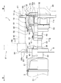
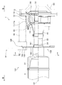
- FIG. 3 is a sectional view taken along the line III-III in FIG. 2. It is an enlarged view which expanded the rear universal joint of 2nd Embodiment.
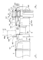
- FIG. 5 is a sectional view taken along line VV of FIG. 4. It is a perspective view of the protection member of 3rd Embodiment. It is an enlarged view which expanded the rear universal joint of 4th Embodiment. It is the enlarged view which expanded the back side universal joint of 5th Embodiment.
- the propulsion shaft 1 is mounted on, for example, an FF (Front-engine Front-drive)-based four-wheel drive vehicle.
- the propulsion shaft 1 is disposed below a floor panel (not shown), extends in the front-rear direction of the vehicle, and receives power from a transmission (not shown) at a front portion of the vehicle body as a final reduction gear device (not shown) at a rear portion of the vehicle body.
- the propulsion shaft 1 is a cylindrical steel pipe and is divided into a first pipe 2 and a second pipe 3 in the front-rear direction, and a middle pipe for connecting the first pipe 2 and the second pipe 3 to each other.
- the joint 4 the front universal joint 6 arranged on the front side of the first pipe 2, the rear universal joint 7 arranged on the rear side of the second pipe 3, and the protection member arranged behind the second pipe 3. 8 and.
- a stub shaft 4c of the intermediate universal joint 4 which will be described later is rotatably supported by a bearing structure 5 attached to a floor panel (not shown).
- the intermediate universal joint 4 a tripod type constant velocity joint is used.
- the tripod type constant velocity joint is a cylindrical outer ring 4a joined to the front end of the second pipe 3, a power transmission member 4b swinging inside the outer ring 4a, and a solid shaft member connected to the power transmission member 4b. And a stub shaft 4c.
- the intermediate universal joint 4 of the present invention is not limited to a constant velocity joint, and a cross joint may be used. Further, when the constant velocity joint is used in the present invention, it is not limited to the tripod type constant velocity joint, and may be a bar field type, a double offset type or the like, and is not particularly limited.
- the rear universal joint 7 is a Barfield type constant velocity joint.
- the Burfield type constant velocity joint includes an outer ring 10, an inner ring 20, a plurality of balls (not shown), a stub shaft 30 as a shaft member, a bellows section 40, and a boot adapter 50.
- the outer ring 10 is a forged component that includes a cylindrical main body 11 that opens in the front and rear, and a ring-shaped flange 12 that extends radially outward from the outer peripheral surface 11 a of the main body 11.
- the inner peripheral surface of the main body 11 is formed in a spherical shape.
- the flange 12 is a portion for connecting to a companion flange 60 (see a broken line in FIG.
- the flange 12 is formed with six bolt holes 13 penetrating in the direction of the rotation axis O1 at equal intervals in the circumferential direction (only one is shown in FIG. 2).
- the inner ring 20 has a cylindrical shape, and a hole spline 21 is formed on the inner peripheral surface of the inner ring 20.
- the outer peripheral surface of the inner ring 20 is formed in a spherical shape.
- a plurality of arc-shaped inner grooves are formed in the circumferential direction, the arc-shaped inner grooves extending in the front-rear direction.
- a cage 23 is fitted on the outer peripheral surface of the inner ring 20.
- the cage 23 has a window (not shown) that is an opening.
- the ball is a metallic sphere.
- the ball is partly exposed from the window of the cage 23 while being housed in the inner groove of the inner ring 20. Further, the portion of the ball exposed from the window portion to the outside is in the outer groove of the outer ring 10.
- the balls 30 rolling between the inner groove 22 of the inner ring 20 and the outer groove 11b of the outer ring 10 are equal to each other in angle between the outer ring 10 serving as the input shaft and the inner ring 20 serving as the output shaft. It works as if it were placed on the line. By this action, power is transmitted to the input shaft and the output shaft without causing rotational fluctuation.
- the stub shaft 30 is a shaft member that extends in the direction of the rotation axis O1, and includes a large diameter portion 31 arranged at the front portion, a small diameter portion 32 arranged at the rear portion, and a large diameter portion 31 and a small diameter portion 32. And an intermediate portion 33 interposed therebetween.
- the outer diameter of the large-diameter portion 31 is circular and has the same diameter as the second pipe 3, and is larger than the small-diameter portion 32 and the intermediate portion 33. Further, the front end of the large diameter portion 31 is joined to the second pipe 3 by welding.
- a shaft spline 32a is formed on the outer peripheral surface of the small diameter portion 32, and the shaft spline 32a and the hole spline 21 of the inner ring 20 are spline-fitted.
- the front end 41 of the bellows portion 40 fastened by the band 43 is attached to the rear portion of the intermediate portion 33.
- a fitted portion 34 to which a mounting portion 81 of the protective member 8 described later is fitted is formed at the front portion of the intermediate portion 33. Further, a step surface 35 extending outward in the radial direction is formed on the front side of the fitted portion in the intermediate portion 33, and the protection member 8 is regulated so as not to move forward.
- the bellows portion 40 is a rubber component that closes the front opening of the outer ring 10, has a substantially J shape in cross section, and has a concave portion 44 that opens forward.
- the boot adapter 50 is a cylindrical metal component, and the rear end 51 is fitted into the outer peripheral surface 11 a of the outer ring 10 and is caulked. The front end 52 of the boot adapter 50 is folded back inward and holds the rear end 42 of the bellows portion 40.
- the protection member 8 is a thin plate-shaped component that is formed by processing a metal plate.
- the protective member 8 is formed on a cylindrical mounting portion 81 that is fitted onto the fitted portion 34, a main body portion 82 that extends radially outward from the front end of the mounting portion 81, and further on the outer peripheral side of the main body portion 82.
- the closed portion 83 is provided.
- the main body 82 has a circular plate shape centered on the rotation axis O1.
- the outer diameter of the main body portion 82 is r1, which is smaller than the outer diameter r2 of the outer ring 10. Therefore, the outer peripheral edge 82a of the main body portion 82 is located radially inward of the outer peripheral surface 11a of the outer ring 10, and an annular relief portion (space) 84 is formed on the outer peripheral side of the outer peripheral edge 82a of the main body portion 82. ing.
- the closing portion 83 is a portion for closing the front of the escape portion 84.
- the closing portion 83 includes a front and rear cylinder 83a that extends forward from the outer end of the main body portion 82, and a disk portion and 83b that extend radially outward from the front end of the front and rear cylinder 83a.
- the length of the front-rear cylinder 83a in the front-rear direction is formed such that the disk portion and 83b do not interfere with a bolt fastening tool 91 described later.
- the flange 12 of the outer ring 10 and the flange 61 of the companion flange 60 are butted against each other, and a bolt (not shown) is inserted from the front of the bolt hole 13 and screwed with a nut (not shown). Further, the bolt is rotated to fasten the flange 12 and the flange 61. After the bolts are inserted through the bolt holes 13 and fastened, the tightening torque of the bolts and nuts is set to a predetermined value.
- the engaging portion 92 of the bolt fastening tool 91 interferes with the outer peripheral surface 11a of the outer race 10 and cannot be engaged. Therefore, the rear end of the extension 90 is fitted on the head of the bolt, and the bolt fastening tool 91 is engaged with the front end of the extension 90. According to this, a part of the engaging portion 92 of the bolt fastening tool 91 is arranged in the escape portion 84 of the protection member 8 (see FIGS. 2 and 3 ).
- the bolt fastening tool 91 is rotated around the center O2 of the bolt hole 13 while the tool (not shown) is retained by the nut so as not to rotate, and the tightening torque is set to a predetermined value.
- the tightening torque of each bolt is set to a predetermined value, the mounting work is completed.
- the bolt fastening tool 91 does not interfere with the protection member 8 when tightening the bolt, the bolt tightening work can be easily performed. Further, since the protective member 8 includes the main body portion 82 and the closing portion 83, it is difficult for pebbles and the like to enter the concave portion 44 of the bellows portion 40.
- the propulsion shaft 101 of 2nd Embodiment is demonstrated.
- the protective member 108 of the propulsion shaft 101 extends in the radial direction from the front end of the cylindrical mounting portion 181 that is externally fitted to the fitted portion 34 and the mounting portion 181.
- the main body 182 and six projecting pieces 183 that further project from the main body 182 radially outward are provided.
- the main body 182 extends to the outer peripheral side of the intermediate portion 33 of the stub shaft 30 and is located radially inward of the outer peripheral surface 11 a of the main body 11 of the outer ring 10 (FIG. 5 ). See auxiliary line L).
- the protruding piece 183 protrudes radially outward beyond the outer peripheral surface 11a of the outer ring 10.
- the protruding pieces 183 are arranged on the outer peripheral side of the main body 182 while being separated from each other, and the escape portions (spaces) 184 are formed between the protruding pieces 183.
- the protruding piece 183 is arranged so as not to overlap the bolt hole 13 of the outer ring 10 when viewed from the axial direction, and the escape portion 184 overlaps the bolt hole 13 of the outer ring 10. As shown in FIG. 4, a bent portion 185 that bends backward is formed at the outer peripheral end of the protruding piece 183, and the strength of the protruding piece 183 is improved.
- the protective member 208 of the propulsion shaft 201 includes a cylindrical mounting portion 181 fitted onto the fitted portion 34, and a main body portion 182 extending radially outward from the front end of the mounting portion 181. And six projecting pieces 183 projecting further outward in the radial direction from the main body section 182, and a closing section 285 that closes the front of the escape section 184. Therefore, the protection member 208 is different from the protection member 108 of the second embodiment in that the protection member 208 includes the closing portion 285.
- the blocking portion 285 includes a substantially U-shaped extending portion 285a that extends forward from the edge portion 184a of the escape portion 184, and a plate portion 285b that is continuous with the front end of the escape portion 284 and that extends in the vertical and horizontal directions. Is equipped with.
- the third embodiment as in the first and second embodiments, it is possible to obtain the effect of facilitating the bolt tightening work. Further, since the front of the escape portion 184 is closed by the closing portion 285, it is more difficult for pebbles and the like to enter the concave portion 44 of the bellows portion 40 than in the protection member 108 of the second embodiment.
- the protection member 308 of the propulsion shaft 301 includes a mounting portion 81 that is externally fitted to the fitted portion 34, a main body portion 82 that extends radially outward from the front end of the mounting portion 81, and a main body.
- a closing portion 83 that is formed on the outer peripheral side of the portion 82 and closes the front of the escape portion 384, and an extending portion 385 that extends rearward from the rear end of the mounting portion 81 are provided. Therefore, the protection member 308 is different from the protection member 108 of the second embodiment in that the protection member 308 includes the extending portion 385.
- the extending portion 385 extends along the stub shaft 30 and has a cylindrical shape.
- the rear end portion 385a of the extending portion 385 covers the outer peripheral side of the front end 41 of the bellows portion 40 and is fastened together with the front end 41 of the bellows portion 40 by the band 43.
- the fourth embodiment similar to the above-described embodiments, it is possible to obtain the effect that the bolt tightening work becomes easy. Further, the fixing strength of the protection member 308 is improved. Further, the number of parts is reduced and cost can be reduced as compared with the case where the protective member 308 and the band 43 for fastening the bellows portion 40 are respectively prepared.
- the propulsion shaft 401 of 5th Embodiment includes a first pipe 2, a second pipe 3, an intermediate universal joint 4, a front universal joint 6, a rear universal joint 407, and a protective member 408. There is.
- the rear universal joint 407 is a cross-clove type constant velocity joint, and includes an outer ring 410, an inner ring 420, a plurality of balls (not shown), a stub shaft 430, a bellows section 440, and a boot adapter 450. I have it. Since the stub shaft 430 and the bellows portion 440 have the same configurations as the stub shaft 30 and the bellows portion 40 described in the first embodiment, the description thereof will be omitted.
- the outer ring 410 is composed of a cylindrical main body portion 411 that is open at the front and rear.
- a plurality of bolt holes 413 are formed in the body portion 411 in the circumferential direction so as to penetrate the front end surface and the rear end surface.
- a hole spline 421 is formed on the inner peripheral surface of the inner ring 420, and is spline-fitted with the small diameter portion 432 of the stub shaft 430.
- a cage 423 is fitted on the outer peripheral surface of the inner ring 420. The ball is partly exposed from the window (not shown) of the cage 423 while being housed in the inner groove (not shown) of the inner ring 420.
- a ball that slides between an inner groove of the inner ring 420 and an outer groove (not shown) of the outer ring 410 forms the angle between the outer ring 410 serving as the input shaft and the inner ring 420 serving as the output shaft. It works as if it were placed on the bisector. By this action, power is transmitted to the input shaft and the output shaft without causing rotational fluctuation.
- the boot adapter 450 includes an outer fitting portion 451 which is fitted onto the outer peripheral surface of the main body portion 411 of the outer ring 410, a folding back portion 452 which is folded back radially inward from a front end of the outer fitting portion 451, and a folding back portion 452.
- a cylindrical portion 453 that extends forward from the end and a holding portion 454 that holds the rear end 442 of the bellows portion 440 by folding the front end of the cylindrical portion 453 inward in the radial direction are provided.
- the protective member 408 is formed on the cylindrical mounting portion 481 fitted onto the stub shaft 430, the main body portion 482 extending radially outward from the front end of the mounting portion 481, and further on the outer peripheral side of the main body portion 484.
- the closed portion 483 is provided, and an annular escape portion (space) 484 is formed on the outer peripheral side of the outer peripheral edge 482a of the main body portion 482.
- the outer shape of the main body portion 482 is circular with the rotation axis O1 as the center, and the outer diameter of the main body portion 482 is set smaller than the outer diameter of the cylindrical portion 453 of the boot adapter 450 (auxiliary portion in FIG. 8). See line M).
- the main body portion 482 when viewed from the direction of the rotation axis O1, the main body portion 482 is located radially inward of the outer peripheral surface 453a of the cylindrical portion 453. Since the bolt B inserted into the bolt hole 413 and fastening the main body portion 411 has a small gap between the outer peripheral surface of the head portion and the cylindrical portion 453, a head portion having a hexagonal hole B1 is used. Has been. Further, a washer W is interposed between the main body 411 and the head of the bolt B.
- the hexagonal shaft 90a formed at the tip of the extension 90 is inserted into the hexagonal hole B1 of the bolt B, and the engaging portion 92 of the bolt fastening tool 91 is attached to the front end of the extension 90.
- a part of the engaging portion 92 is arranged in the escape portion 484 and does not interfere with the protection member 408. Therefore, the tightening work of the bolt B becomes easy.
- the protection member 8 is not limited to a steel plate material, and may be formed of hard rubber or the like. Further, a ring that abuts the rear end surface of the main body of the protection member may be externally fitted to the intermediate portion of the stub shaft 30. According to this, the rearward movement of the protective member is restricted, and the fixing strength is improved.
- the Burfield type constant velocity joint and the cross clove type constant velocity joint were mentioned, but tripod type and double offset type constant velocity joints may be used. Further, in the case of using a tripod type or double offset type constant velocity joint, as described in the first embodiment, at least a part of the relief portion is located radially inward of the outer peripheral surface of the main body portion of the outer ring. It must be formed so that it is located.
Landscapes
- Engineering & Computer Science (AREA)
- General Engineering & Computer Science (AREA)
- Mechanical Engineering (AREA)
- Chemical & Material Sciences (AREA)
- Combustion & Propulsion (AREA)
- Transportation (AREA)
- Ocean & Marine Engineering (AREA)
- Motor Power Transmission Devices (AREA)
- Diaphragms And Bellows (AREA)
- Sealing Devices (AREA)
- Shafts, Cranks, Connecting Bars, And Related Bearings (AREA)
Abstract
軸方向に貫通する複数のボルト穴(13)が形成された外輪(10)と、外輪(10)内に揺動自在に配置された動力伝達部材と、前端部に大径部(31が形成され後端部が動力伝達部材に連結する軸部材(30)と、外輪(30)の前側開口を封止するゴム製の封止部材(40)と、軸部材(30)の大径部(31)と後端部との間に装着された円盤状の保護部材(108)と、を備え、保護部材(108)には、ボルト締結工具(91)に対する逃げ部(84)が形成され、逃げ部(84)は、軸心(O1)を中心とする環状を成している。
Description
本発明は、推進軸に関する。
推進軸は、車両の前後方向に延在する動力伝達軸であり、原動機で発生し変速機で所定速度に減速された動力を終減速装置に伝達する。推進軸は、変速機や終減速装置と連結するため、両端に自在継手が設けられている。自在継手には、一般的に十字軸継手が利用されるが、動力伝達系の振動の発生を抑制するため、等速ジョイントが利用される場合がある。
等速ジョイントは、外輪と、外輪内に配置される内輪と、外輪と内輪との間に介在し動力(トルク)を伝達する動力伝達部材(例えば複数の球体)と、一端部が内輪にスプライン嵌合し他端部がパイプに接合する軸部材と、を備えている。
また、外輪内に封入された潤滑用グリースの流出を防止するため、及び外輪内へのダストの浸入を防止するため、ブーツで外輪の開口を封止している。ブーツは、外輪に外嵌される金属製のブーツアダプタ(円筒部材)と、一端がブーツアダプタに固定され他端が軸部材に固定されるゴム製のベロー部(封止部材)とにより構成されるのが一般的である(特許文献1参照)。
また、外輪内に封入された潤滑用グリースの流出を防止するため、及び外輪内へのダストの浸入を防止するため、ブーツで外輪の開口を封止している。ブーツは、外輪に外嵌される金属製のブーツアダプタ(円筒部材)と、一端がブーツアダプタに固定され他端が軸部材に固定されるゴム製のベロー部(封止部材)とにより構成されるのが一般的である(特許文献1参照)。
また、ベロー部は、前後方向の一方に窪む凹状部を有しており、この凹状部が前方を向いている場合、前輪が跳ね上げた小石や融雪が凹状部内に入り、ベロー部が破損するおそれがある。よって、特許文献2では、ベロー部の前方に円盤状の保護部材を配置することが提案されている。
ところで、終減速装置の入力軸と連結するため、外輪には軸方向に貫通するボルト穴が周方向に複数形成されている。このため、ボルト穴に挿通されたボルトをボルト締結工具で締め付けようとすると、ボルト締結工具が保護部材に干渉するおそれがある。
これに対し、ボルト締結工具と保護部材との干渉を防止するため、保護部材を外輪から離間して配置すると、小石等がベロー部の凹状部内に入り易くなる。これを防止すべく保護部材を大型化すると、車両のレイアウトに影響を与えるため好ましくない。
これに対し、ボルト締結工具と保護部材との干渉を防止するため、保護部材を外輪から離間して配置すると、小石等がベロー部の凹状部内に入り易くなる。これを防止すべく保護部材を大型化すると、車両のレイアウトに影響を与えるため好ましくない。
本発明は、このような課題を解決するために創作されたものであり、保護部材を備えつつ車両への取り付け作業性を確保できる推進軸を提供することを目的とする。
前記課題を解決するため、第1発明に係る推進軸は、軸方向に貫通する複数のボルト穴が形成された外輪と、前記外輪内に揺動自在に配置された動力伝達部材と、前端部に大径部が形成され後端部が前記動力伝達部材に連結する軸部材と、前記外輪の前側開口を封止するゴム製の封止部材と、前記軸部材の大径部と後端部との間に装着された円盤状の保護部材と、を備え、前記保護部材には、ボルト締結工具に対する逃げ部が形成され、前記逃げ部は、軸心を中心とする環状を成していることを特徴とする。
また、前記課題を解決するため、第2発明に係る推進軸は、軸方向に貫通する複数のボルト穴が形成された外輪と、前記外輪内に揺動自在に配置された動力伝達部材と、前端部に大径部が形成され後端部が前記動力伝達部材に連結する軸部材と、前記外輪の前側開口を封止するゴム製の封止部材と、前記軸部材の大径部と後端部との間に装着された円盤状の保護部材と、を備え、前記保護部材には、軸方向から視て前記ボルト穴と同位相に配置され、ボルト締結工具に対する逃げ部が形成されていることを特徴とする。
前記する第1発明及び第2発明によれば、ボルトを締め付ける際、ボルト締結工具が保護部材の逃げ部内に配置され、工具が保護部材と干渉しない。よって、車両への取り付け作業性を確保できる。
また、前記第2発明において、前記保護部材には、前記逃げ部の縁部から前方に延びて前記逃げ部の前側を閉塞する閉塞部が形成されていることが好ましい。前記構成によれば、逃げ部に向って前方から飛んで来る小石等は閉塞部により接触し、封止部材の凹状部内に入り込まない。
また、前記第2発明において、前記保護部材における前記逃げ部の縁部は切り欠かれていてもよい。前記構成によれば、保護部材の形状が簡易となり製造コストが低減する。
また、前記第1発明及び第2発明において、前記保護部材は、前記軸部材に嵌合してもよい。又は、前記保護部材は、前記軸部材に挿通されるとともに前記軸部材に装着されたリング部材により抜け止めされていてもよい。若しくは、前記保護部材は、前記軸部材に挿通されるとともに締め付けバンドにより締め付けられていてもよい。
また、前記締め付けバンドは、前記封止部材の端部も締め付けていることが好ましい。前記構成によれば、封止部材を締め付ける締め付けバンドの部品点数を削減することができる。
また、前記第1発明及び第2発明において、後端部が前記外輪に固定され、前端部が前記封止部材を支持する円筒部材と、を備え、前記ボルト穴は、前記外輪の本体部に形成され、前記逃げ部の少なくとも一部は、前記円筒部材の外周面よりも径方向内側に位置していてもよい。または、前記ボルト穴は、前記外輪のフランジに形成され、前記逃げ部の少なくとも一部は、前記外輪の本体部の外周面よりも径方向内側に位置していてもよい。
本発明の推進軸によれば、保護部材を備えつつ車両への取り付け作業性を確保できる。
続いて各実施形態の推進軸1,101,201,301,401について図面を参照しながら説明する。各実施形態で共通する技術的要素には、共通の符号を付するとともに説明を省略する。
(第1実施形態)
推進軸1は、例えばFF(Front-engine Front-drive)ベースの四輪駆動車に搭載される。推進軸1は、フロアパネル(不図示)の下方に配置され、車両の前後方向に延在し、車体前部の変速装置(不図示)からの動力を車体後部の終減速装置(不図示)に伝達する。
図1に示すように、推進軸1は、円筒状の鋼管であって前後に分割された第1パイプ2及び第2パイプ3と、第1パイプ2と第2パイプ3とを接続する中間自在継手4と、第1パイプ2の前側に配置された前側自在継手6と、第2パイプ3の後側に配置された後側自在継手7と、第2パイプ3の後方に配置された保護部材8と、を備えている。
また、推進軸1において、中間自在継手4の後述するスタブシャフト4cは、フロアパネル(不図示)に取り付けられた軸受構造体5によって回転自在に支持されている。
中間自在継手4には、トリポード型の等速ジョイントが用いられている。トリポード型の等速ジョイントは、第2パイプ3の前端に接合された円筒状の外輪4aと、外輪4a内を揺動する動力伝達部材4bと、動力伝達部材4bに連結する中実の軸部材であるスタブシャフト4cと、を備えている。
なお、本発明の中間自在継手4は、等速ジョイントに限定されず、十字軸継手を用いてもよい。また、本発明において等速ジョイントを用いる場合、トリポード型の等速ジョイントに限定されず、バーフィールド型やダブルオフセット型等であってもよく、特に限定されない。
なお、本発明の中間自在継手4は、等速ジョイントに限定されず、十字軸継手を用いてもよい。また、本発明において等速ジョイントを用いる場合、トリポード型の等速ジョイントに限定されず、バーフィールド型やダブルオフセット型等であってもよく、特に限定されない。
前側自在継手6及び後側自在継手7には、同一の等速ジョイントが用いられている。よって、代表例として後側自在継手7を説明し、前側自在継手6の説明を省略する。
図2に示すように、後側自在継手7は、バーフィールド型の等速ジョイントが用いられている。バーフィールド型の等速ジョイントは、外輪10と、内輪20と、複数のボール(不図示)と、軸部材であるスタブシャフト30と、ベロー部40と、ブーツアダプタ50と、を備えている。
図2に示すように、後側自在継手7は、バーフィールド型の等速ジョイントが用いられている。バーフィールド型の等速ジョイントは、外輪10と、内輪20と、複数のボール(不図示)と、軸部材であるスタブシャフト30と、ベロー部40と、ブーツアダプタ50と、を備えている。
外輪10は、前後に開口する円筒状の本体部11と、本体部11の外周面11aから径方向外側に延びるリング状のフランジ12と、を備えた鍛造部品である。
本体部11の内周面は、球面状に形成されている。本体部11の内周面には、前後に延在し断面視で円弧状の外溝(不図示)が周方向に複数形成されている。
フランジ12は、終減速装置(不図示)の入力軸に連結するコンパニオンフランジ60(図2の破線参照)と連結するための部位であり、本体部11の外周面11aの後端に位置している。フランジ12には、回転軸O1方向に貫通するボルト穴13が周方向に6つ等間隔で形成されている(図2において1つのみ図示)。
本体部11の内周面は、球面状に形成されている。本体部11の内周面には、前後に延在し断面視で円弧状の外溝(不図示)が周方向に複数形成されている。
フランジ12は、終減速装置(不図示)の入力軸に連結するコンパニオンフランジ60(図2の破線参照)と連結するための部位であり、本体部11の外周面11aの後端に位置している。フランジ12には、回転軸O1方向に貫通するボルト穴13が周方向に6つ等間隔で形成されている(図2において1つのみ図示)。
内輪20は円筒状を呈しており、内輪20の内周面に穴スプライン21が形成されている。内輪20の外周面は球面状に形成されている。また、内輪20の外周面には、前後方向に延在し断面視で円弧状の内溝(不図示)が周方向に複数形成されている。さらに、内輪20の外周面にはケージ23が嵌め込まれている。ケージ23には、開口である窓部(不図示)が形成されている。
ボールは、金属製の球体である。ボールは、内輪20の内溝内に収容されつつ一部がケージ23の窓部から露出している。また、ボールにおいて窓部から外側に露出する部分は、外輪10の外溝に入り込んでいる。
ケージ23は、内輪20の内溝22と、外輪10の外溝11bとの間で転動するボール30が、入力軸となる外輪10と、出力軸となる内輪20とのなす角度の二等分線上に配置されるような働きをする。この働きにより入力軸と出力軸は回転変動を生じることなく動力が伝達される。
ケージ23は、内輪20の内溝22と、外輪10の外溝11bとの間で転動するボール30が、入力軸となる外輪10と、出力軸となる内輪20とのなす角度の二等分線上に配置されるような働きをする。この働きにより入力軸と出力軸は回転変動を生じることなく動力が伝達される。
スタブシャフト30は、回転軸O1方向に延在する軸部材であり、前部に配置された大径部31と、後部に配置された小径部32と、大径部31と小径部32との間に介在する中間部33と、を備えている。
大径部31の外形は、円形状を呈するともに第2パイプ3と同径に形成され、小径部32、中間部33よりも大径に形成されている。また、大径部31の前端は第2パイプ3と溶接により接合している。
小径部32の外周面には、軸スプライン32aが形成されており、この軸スプライン32aと内輪20の穴スプライン21とがスプライン嵌合している。
中間部33の後部には、バンド43により締め付けられたベロー部40の前端41が取り付けられている。
中間部33の前部には、保護部材8の後述する装着部81が外嵌する被嵌合部34が形成されている。また、中間部33において被嵌合部の前側には、径方向外側に延出する段差面35が形成され、保護部材8が前方に移動しないように規制されている。
小径部32の外周面には、軸スプライン32aが形成されており、この軸スプライン32aと内輪20の穴スプライン21とがスプライン嵌合している。
中間部33の後部には、バンド43により締め付けられたベロー部40の前端41が取り付けられている。
中間部33の前部には、保護部材8の後述する装着部81が外嵌する被嵌合部34が形成されている。また、中間部33において被嵌合部の前側には、径方向外側に延出する段差面35が形成され、保護部材8が前方に移動しないように規制されている。
ベロー部40は、外輪10の前側開口を閉塞するゴム製の部品であり、断面視で略J字状となっており、前方に開口する凹状部44を有している。
ブーツアダプタ50は、円筒状を呈する金属製の部品であり、後端51が外輪10の外周面11aに嵌め込まれるとともに加締められている。ブーツアダプタ50の前端52は、内側に折り返されてベロー部40の後端42を挟持している。
ブーツアダプタ50は、円筒状を呈する金属製の部品であり、後端51が外輪10の外周面11aに嵌め込まれるとともに加締められている。ブーツアダプタ50の前端52は、内側に折り返されてベロー部40の後端42を挟持している。
保護部材8は、金属板を加工することで形成されており薄板状の部品である。
保護部材8は、被嵌合部34に外嵌される円筒状の装着部81と、装着部81の前端から径方向外側に延出する本体部82と、本体部82のさらに外周側に形成された閉塞部83と、を備えている。
保護部材8は、被嵌合部34に外嵌される円筒状の装着部81と、装着部81の前端から径方向外側に延出する本体部82と、本体部82のさらに外周側に形成された閉塞部83と、を備えている。
図3に示すように、本体部82は、回転軸O1を中心とする円形板状を呈している。本体部82の外径はr1となっており、外輪10の外径r2よりも小径に形成されている。
よって、本体部82の外周縁82aは、外輪10の外周面11aよりも径方向内側に位置し、本体部82の外周縁82aの外周側には、環状の逃げ部(空間)84が形成されている。
よって、本体部82の外周縁82aは、外輪10の外周面11aよりも径方向内側に位置し、本体部82の外周縁82aの外周側には、環状の逃げ部(空間)84が形成されている。
閉塞部83は、逃げ部84の前方を閉塞するための部位である。
閉塞部83は、本体部82の外端から前方に延びる前後筒83aと、前後筒83aの前端から径方向外側に延びる円盤部と83bと、を備えている。
前後筒83aの前後方向の長さは、円盤部と83bが後述するボルト締結工具91と干渉しない程度に形成されている。
閉塞部83は、本体部82の外端から前方に延びる前後筒83aと、前後筒83aの前端から径方向外側に延びる円盤部と83bと、を備えている。
前後筒83aの前後方向の長さは、円盤部と83bが後述するボルト締結工具91と干渉しない程度に形成されている。
次に、推進軸1の取り付け作業を説明する。
外輪10のフランジ12とコンパニオンフランジ60のフランジ61とを突き合わせ、図示しないボルトをボルト穴13の前方から挿通し、図示しないナットと螺合させる。また、ボルトを回転させてフランジ12とフランジ61を締結する。
各ボルト穴13にボルトを挿通し締結したら、次に、ボルト及びナットの締め付けトルクを所定値に設定する。
ここで、ボルト締結工具91を直接ボルトの頭部に係合させようとすると、ボルト締結工具91の係合部92が外輪10の外周面11aに干渉して係合できない。よって、ボルトの頭部にエクステンション90の後端を嵌め、エクステンション90の前端にボルト締結工具91を係合させる。これによれば、ボルト締結工具91の係合部92の一部は、保護部材8の逃げ部84内に配置される(図2、図3参照)。
次に、図示しない工具をナットに係止させて回転しないように保持しつつ、ボルト締結工具91をボルト穴13の中心O2回りに回動し、締め付けトルクを所定値に設定する。各ボルトの締め付けトルクが所定値に設定されたら、取り付け作業が終了する。
以上、第1実施形態によれば、ボルトを締め付ける際、ボルト締結工具91が保護部材8と干渉しないため、ボルトの締め付け作業が容易に行うことができる。また、保護部材8は、本体部82と閉塞部83を備えるため、小石等がベロー部40の凹状部44内に入り込み難い。
(第2実施形態)
次に第2実施形態の推進軸101について説明する。
図4、図5に示すように、推進軸101の保護部材108は、被嵌合部34に外嵌される円筒状の装着部181と、装着部181の前端から径方向外側に延出する本体部182と、本体部182からさらに径方向外側に突出する6つの突出片183と、を備えている。
次に第2実施形態の推進軸101について説明する。
図4、図5に示すように、推進軸101の保護部材108は、被嵌合部34に外嵌される円筒状の装着部181と、装着部181の前端から径方向外側に延出する本体部182と、本体部182からさらに径方向外側に突出する6つの突出片183と、を備えている。
図5に示すように、本体部182は、スタブシャフト30の中間部33の外周側に延在し、外輪10の本体部11の外周面11aよりも径方向内側に位置している(図5の補助線L参照)。
一方で、突出片183は、外輪10の外周面11aを超えて径方向外側に突出している。突出片183は、互いに離間しながら本体部182の外周側に配置され、突出片183の間に逃げ部(空間)184が形成されている。
さらに、突出片183は、軸方向から視た場合、外輪10のボルト穴13と重ならないように配置されており、逃げ部184が外輪10のボルト穴13と重なっている。
図4に示すように、突出片183の外周端には、後方へ屈曲する屈曲部185が形成され、突出片183の強度が向上している。
一方で、突出片183は、外輪10の外周面11aを超えて径方向外側に突出している。突出片183は、互いに離間しながら本体部182の外周側に配置され、突出片183の間に逃げ部(空間)184が形成されている。
さらに、突出片183は、軸方向から視た場合、外輪10のボルト穴13と重ならないように配置されており、逃げ部184が外輪10のボルト穴13と重なっている。
図4に示すように、突出片183の外周端には、後方へ屈曲する屈曲部185が形成され、突出片183の強度が向上している。
以上、第2実施形態によれば、エクステンション90を用いてボルトBを締め付ける際、ボルト締結工具91の係合部92の一部が逃げ部184に配置され、保護部材108と干渉しない。
(第3実施形態)
次に第3実施形態の推進軸201について説明する。
図6に示すように、推進軸201の保護部材208は、被嵌合部34に外嵌される円筒状の装着部181と、装着部181の前端から径方向外側に延出する本体部182と、本体部182からさらに径方向外側に突出する6つの突出片183と、逃げ部184の前方を閉塞する閉塞部285と、を備えている。よって、保護部材208は、閉塞部285を備えている点において、第2実施形態の保護部材108と異なる。
閉塞部285は、逃げ部184の縁部184aから前方に延出する略U字状の延出部285aと、逃げ部284の前端に連続し上下及び左右方向に延在する板部285bと、を備えている。
以上、第3実施形態によれば、第1実施形態及び第2実施形態と同様に、ボルトの締め付け作業が容易となる、という効果を得ることができる。また、閉塞部285により逃げ部184の前方が閉塞されるため、第2実施形態の保護部材108よりも小石等がベロー部40の凹状部44内に入り込み難い。
(第4実施形態)
次に第4実施形態の推進軸301について説明する。
図7に示すように、推進軸301の保護部材308は、被嵌合部34に外嵌される装着部81と、装着部81の前端から径方向外側に延出する本体部82と、本体部82のさらに外周側に形成され逃げ部384の前方を閉塞する閉塞部83と、装着部81の後端から後方に延出する延出部385と、を備えている。よって、保護部材308は、延出部385を備えている点において、第2実施形態の保護部材108と異なる。
延出部385は、スタブシャフト30に沿って延在し、円筒状を呈している。延出部385の後端部385aは、ベロー部40の前端41の外周側を覆うとともに、バンド43によりベロー部40の前端41とともに締め付けられている。
以上、第4実施形態によれば、前記した実施形態と同様に、ボルトの締め付け作業が容易となる、という効果を得ることができる。また、保護部材308の固定強度が向上する。また、保護部材308とベロー部40を締め付けるバンド43をそれぞれ用意した場合よりも部品点数が低減し、コストの削減化を図ることができる。
(第5実施形態)
次に第5実施形態の推進軸401について説明する。
図8に示すように、推進軸401は、第1パイプ2及び第2パイプ3と、中間自在継手4と、前側自在継手6と、後側自在継手407と、保護部材408と、を備えている。
次に第5実施形態の推進軸401について説明する。
図8に示すように、推進軸401は、第1パイプ2及び第2パイプ3と、中間自在継手4と、前側自在継手6と、後側自在継手407と、保護部材408と、を備えている。
後側自在継手407は、クロスクローブ型の等速ジョイントであり、外輪410と、内輪420と、複数のボール(不図示)と、スタブシャフト430と、ベロー部440と、ブーツアダプタ450と、を備えている。なお、スタブシャフト430と、ベロー部440とについては、第1実施形態で説明したスタブシャフト30、ベロー部40と同一構成であるため、説明を省略する。
外輪410は、前後に開口する円筒状の本体部411により構成されている。本体部411には、前端面と後端面とを貫通するボルト穴413が周方向に複数形成されている。
内輪420の内周面には、穴スプライン421が形成され、スタブシャフト430の小径部432とスプライン嵌合している。内輪420の外周面には、ケージ423が嵌め込まれている。
ボールは、内輪420の内溝(不図示)内に収容されつつ一部がケージ423の窓部(不図示)から露出している。また、ボールにおいて窓部から外側に露出する部分は、外輪410の外溝(不図示)に入り込んでいる。
ケージ423は、内輪420の内溝と、外輪410の外溝(不図示)との間で摺動するボールが、入力軸となる外輪410と、出力軸となる内輪420とのなす角度の二等分線上に配置されるような働きをする。この働きにより入力軸と出力軸は回転変動を生じることなく動力が伝達される。
ブーツアダプタ450は、外輪410の本体部411の外周面に外嵌される外嵌部451と、外嵌部451の前端端から径方向内側に折り返された折り返し部452と、折り返し部452の内端から前方に延在する円筒部453と、円筒部453の前端を径方向内側に折り返してベロー部440の後端442を挟持する挟持部454と、を備えている。
保護部材408は、スタブシャフト430に外嵌される円筒状の装着部481と、装着部481の前端から径方向外側に延出する本体部482と、本体部484のさらに外周側に形成された閉塞部483と、を備えており、本体部482の外周縁482aの外周側には、環状の逃げ部(空間)484が形成されている。
いる。
本体部482の外形は、回転軸O1を中心とする円形を呈しており、本体部482の外径は、ブーツアダプタ450における円筒部453の外径よりも小さく設定されている(図8の補助線M参照)。このため、回転軸O1方向から視ると、本体部482は、円筒部453の外周面453aよりも径方向内側に位置している。
なお、ボルト穴413に挿入され本体部411を締結するボルトBは、頭部の外周面と円筒部453との隙間が小さいことから、頭部に六角形状の穴B1が形成されたものが用いられている。また、本体部411とボルトBの頭部の間には、ワッシャWが介在している。
いる。
本体部482の外形は、回転軸O1を中心とする円形を呈しており、本体部482の外径は、ブーツアダプタ450における円筒部453の外径よりも小さく設定されている(図8の補助線M参照)。このため、回転軸O1方向から視ると、本体部482は、円筒部453の外周面453aよりも径方向内側に位置している。
なお、ボルト穴413に挿入され本体部411を締結するボルトBは、頭部の外周面と円筒部453との隙間が小さいことから、頭部に六角形状の穴B1が形成されたものが用いられている。また、本体部411とボルトBの頭部の間には、ワッシャWが介在している。
以上、第5実施形態によれば、エクステンション90の先端部に形成された六角軸90aをボルトBの六角形状の穴B1内に挿入し、エクステンション90の前端にボルト締結工具91の係合部92を係合させると、係合部92の一部が逃げ部484に配置され、保護部材408に干渉しない。よって、ボルトBの締め付け作業が容易となる。
以上、各実施形態について説明したが、本発明は、実施形態で説明した例に限定されない。例えば、保護部材8は、鋼板材料に限定せず、硬質ゴム等で成型してもよい。
また、保護部材の本体部の後端面に当接するリングをスタブシャフト30の中間部に外嵌してもよい。これによれば、保護部材が後方に移動することが規制され、固定強度が向上する。
また、保護部材の本体部の後端面に当接するリングをスタブシャフト30の中間部に外嵌してもよい。これによれば、保護部材が後方に移動することが規制され、固定強度が向上する。
また、前側自在継手と後側自在継手として、バーフィールド型等速ジョイントとクロスクローブ型等速ジョイントとを挙げたが、トリポード型やダブルオフセット型の等速ジョイントであってもよい。また、トリポード型やダブルオフセット型の等速ジョイントを用いる場合にあっては、第1実施形態で説明したように、逃げ部の少なくとも一部が外輪の本体部の外周面よりも径方向内側に位置するように形成する必要がある。
1,101,201,301,401 推進軸
7,407 後側自在継手
8,108,208,308,408 保護部材
10,410 外輪
11,411 本体部
12 フランジ
13,413 ボルト穴
30,430 スタブシャフト(軸部材)
40,440 ベロー部
44 凹状部
50,450 ブーツアダプタ
60 コンパニオンフランジ
81,181,481 装着部
82,182,482 本体部
83,285,483 閉塞部
84,184,284,384,484 逃げ部
90 エクステンション
91 ボルト締結工具
92 係合部
183 突出片
385 延出部
453 円筒部
7,407 後側自在継手
8,108,208,308,408 保護部材
10,410 外輪
11,411 本体部
12 フランジ
13,413 ボルト穴
30,430 スタブシャフト(軸部材)
40,440 ベロー部
44 凹状部
50,450 ブーツアダプタ
60 コンパニオンフランジ
81,181,481 装着部
82,182,482 本体部
83,285,483 閉塞部
84,184,284,384,484 逃げ部
90 エクステンション
91 ボルト締結工具
92 係合部
183 突出片
385 延出部
453 円筒部
Claims (10)
- 軸方向に貫通する複数のボルト穴が形成された外輪と、
前記外輪内に揺動自在に配置された動力伝達部材と、
前端部に大径部が形成され後端部が前記動力伝達部材に連結する軸部材と、
前記外輪の前側開口を封止するゴム製の封止部材と、
前記軸部材の大径部と後端部との間に装着された円盤状の保護部材と、を備え、
前記保護部材には、ボルト締結工具に対する逃げ部が形成され、
前記逃げ部は、軸心を中心とする環状を成していることを特徴とする推進軸。 - 軸方向に貫通する複数のボルト穴が形成された外輪と、
前記外輪内に揺動自在に配置された動力伝達部材と、
前端部に大径部が形成され後端部が前記動力伝達部材に連結する軸部材と、
前記外輪の前側開口を封止するゴム製の封止部材と、
前記軸部材の大径部と後端部との間に装着された円盤状の保護部材と、を備え、
前記保護部材には、軸方向から視て前記ボルト穴と同位相に配置され、ボルト締結工具に対する逃げ部が形成されていることを特徴とする推進軸。 - 前記保護部材には、前記逃げ部の縁部から前方に延びて前記逃げ部の前側を閉塞する閉塞部が形成されていることを特徴とする請求項1又は請求項2に記載の推進軸。
- 前記保護部材における前記逃げ部の縁部は切り欠かれていることを特徴とする請求項1又は請求項2に記載の推進軸。
- 前記保護部材は、前記軸部材に嵌合していることを特徴とする請求項1又は請求項2に記載の推進軸。
- 前記保護部材は、前記軸部材に挿通されるとともに前記軸部材に装着されたリング部材により抜け止めされていることを特徴とする請求項1又は請求項2に記載の推進軸。
- 前記保護部材は、前記軸部材に挿通されるとともに締め付けバンドにより締め付けられていることを特徴とする請求項1又は請求項2に記載の推進軸。
- 前記締め付けバンドは、前記封止部材の端部も締め付けていることを特徴とする請求項7に記載の推進軸。
- 後端部が前記外輪に固定され、前端部が前記封止部材を支持する円筒部材と、を備え、
前記ボルト穴は、前記外輪の本体部に形成され、
前記逃げ部の少なくとも一部は、前記円筒部材の外周面よりも径方向内側に位置していることを特徴とする請求項1又は請求項2に記載の推進軸。 - 前記ボルト穴は、前記外輪のフランジに形成され、
前記逃げ部の少なくとも一部は、前記外輪の本体部の外周面よりも径方向内側に位置していることを特徴とする請求項1又は請求項2に記載の推進軸。
Priority Applications (2)
| Application Number | Priority Date | Filing Date | Title |
|---|---|---|---|
| CN201880096750.XA CN112639318B (zh) | 2018-12-04 | 2018-12-12 | 传动轴 |
| US17/188,838 US20210178894A1 (en) | 2018-12-04 | 2021-03-01 | Propeller shaft |
Applications Claiming Priority (2)
| Application Number | Priority Date | Filing Date | Title |
|---|---|---|---|
| JP2018-227612 | 2018-12-04 | ||
| JP2018227612A JP6533860B1 (ja) | 2018-12-04 | 2018-12-04 | 推進軸 |
Related Child Applications (1)
| Application Number | Title | Priority Date | Filing Date |
|---|---|---|---|
| US17/188,838 Continuation US20210178894A1 (en) | 2018-12-04 | 2021-03-01 | Propeller shaft |
Publications (1)
| Publication Number | Publication Date |
|---|---|
| WO2020115918A1 true WO2020115918A1 (ja) | 2020-06-11 |
Family
ID=66934373
Family Applications (1)
| Application Number | Title | Priority Date | Filing Date |
|---|---|---|---|
| PCT/JP2018/045605 Ceased WO2020115918A1 (ja) | 2018-12-04 | 2018-12-12 | 推進軸 |
Country Status (4)
| Country | Link |
|---|---|
| US (1) | US20210178894A1 (ja) |
| JP (1) | JP6533860B1 (ja) |
| CN (1) | CN112639318B (ja) |
| WO (1) | WO2020115918A1 (ja) |
Families Citing this family (2)
| Publication number | Priority date | Publication date | Assignee | Title |
|---|---|---|---|---|
| EP3989796A4 (en) | 2019-06-28 | 2023-06-28 | Endiatx, Inc. | Ingestible device with manipulation capabilities |
| KR102492779B1 (ko) * | 2021-03-05 | 2023-01-27 | 주식회사 디엠에스 | 기판 이송장치 |
Citations (4)
| Publication number | Priority date | Publication date | Assignee | Title |
|---|---|---|---|---|
| JPS6159923U (ja) * | 1984-09-27 | 1986-04-22 | ||
| JPH03129141A (ja) * | 1989-10-14 | 1991-06-03 | Mazda Motor Corp | 車両の動力伝達装置 |
| JPH08216709A (ja) * | 1995-02-16 | 1996-08-27 | Showa:Kk | 推進軸の連結構造 |
| JP2014231869A (ja) * | 2013-05-29 | 2014-12-11 | 日立オートモティブシステムズ九州株式会社 | プロペラシャフト及びプロペラシャフトに用いられる自在継手のヨーク構造 |
Family Cites Families (7)
| Publication number | Priority date | Publication date | Assignee | Title |
|---|---|---|---|---|
| US3362193A (en) * | 1966-06-02 | 1968-01-09 | Bendix Corp | Universal joint |
| JP2011085152A (ja) * | 2009-10-13 | 2011-04-28 | Ntn Corp | 動力伝達用軸およびアッセンブリ体 |
| JP2014005915A (ja) * | 2012-06-26 | 2014-01-16 | Showa Corp | 等速ジョイントの取り付け構造およびプロペラシャフト |
| JP2015017674A (ja) * | 2013-07-11 | 2015-01-29 | 日本精工株式会社 | シールリング付車輪支持用転がり軸受ユニット |
| KR101852281B1 (ko) * | 2014-03-10 | 2018-04-25 | 히다치 오토모티브 시스템즈 가부시키가이샤 | 프로펠러 샤프트 및 이 프로펠러 샤프트에 이용되는 등속 조인트 |
| US9494198B2 (en) * | 2014-11-24 | 2016-11-15 | Ford Global Technologies, Llc | Universal joint with protective shield |
| JP6294394B2 (ja) * | 2016-06-28 | 2018-03-14 | Ntn株式会社 | 車輪用軸受装置 |
-
2018
- 2018-12-04 JP JP2018227612A patent/JP6533860B1/ja active Active
- 2018-12-12 WO PCT/JP2018/045605 patent/WO2020115918A1/ja not_active Ceased
- 2018-12-12 CN CN201880096750.XA patent/CN112639318B/zh active Active
-
2021
- 2021-03-01 US US17/188,838 patent/US20210178894A1/en not_active Abandoned
Patent Citations (4)
| Publication number | Priority date | Publication date | Assignee | Title |
|---|---|---|---|---|
| JPS6159923U (ja) * | 1984-09-27 | 1986-04-22 | ||
| JPH03129141A (ja) * | 1989-10-14 | 1991-06-03 | Mazda Motor Corp | 車両の動力伝達装置 |
| JPH08216709A (ja) * | 1995-02-16 | 1996-08-27 | Showa:Kk | 推進軸の連結構造 |
| JP2014231869A (ja) * | 2013-05-29 | 2014-12-11 | 日立オートモティブシステムズ九州株式会社 | プロペラシャフト及びプロペラシャフトに用いられる自在継手のヨーク構造 |
Also Published As
| Publication number | Publication date |
|---|---|
| CN112639318A (zh) | 2021-04-09 |
| CN112639318B (zh) | 2023-04-11 |
| JP2020090980A (ja) | 2020-06-11 |
| JP6533860B1 (ja) | 2019-06-19 |
| US20210178894A1 (en) | 2021-06-17 |
Similar Documents
| Publication | Publication Date | Title |
|---|---|---|
| JP4442315B2 (ja) | 電動輪 | |
| KR20190130311A (ko) | 허브 일체형 등속조인트 | |
| US8142292B2 (en) | Universal joint with trunnion shaft seal assembly | |
| JP6533860B1 (ja) | 推進軸 | |
| US20160108968A1 (en) | Stopper piece and bearing apparatus | |
| US12188527B2 (en) | Propeller shaft | |
| JP5016528B2 (ja) | プロペラシャフト | |
| JP7063599B2 (ja) | 車両用推進軸 | |
| US9017175B2 (en) | Propshaft assembly | |
| JP2001241459A (ja) | アクスルモジュール | |
| JP2016153285A (ja) | 連結構造体 | |
| JP2008256180A (ja) | 固定式等速自在継手及びその組立方法 | |
| US11242897B2 (en) | Coupling assembly having angled fastener holes | |
| JP2021055733A (ja) | 推進軸の中間軸受構造 | |
| JP6962809B2 (ja) | 車両用推進軸 | |
| US7914382B2 (en) | Dual type constant velocity universal joint | |
| JP7300412B2 (ja) | 自在継手の接続構造 | |
| JP2013253645A (ja) | 等速ジョイントの取り付け構造およびプロペラシャフト | |
| JP3736571B2 (ja) | 駆動輪用転がり軸受ユニット及び車輪用駆動ユニットの製造方法 | |
| US20180363711A1 (en) | Wheel drive unit for vehicle | |
| JP2007078081A (ja) | 摺動型等速自在継手及びその製造方法 | |
| WO2020115917A1 (ja) | 推進軸 | |
| JP2013104480A (ja) | 等速ジョイント | |
| JP2019027570A (ja) | 推進軸 | |
| JP2010025207A (ja) | 等速自在継手 |
Legal Events
| Date | Code | Title | Description |
|---|---|---|---|
| 121 | Ep: the epo has been informed by wipo that ep was designated in this application |
Ref document number: 18942155 Country of ref document: EP Kind code of ref document: A1 |
|
| NENP | Non-entry into the national phase |
Ref country code: DE |
|
| 122 | Ep: pct application non-entry in european phase |
Ref document number: 18942155 Country of ref document: EP Kind code of ref document: A1 |