WO2020111227A1 - 電子機器 - Google Patents
電子機器 Download PDFInfo
- Publication number
- WO2020111227A1 WO2020111227A1 PCT/JP2019/046767 JP2019046767W WO2020111227A1 WO 2020111227 A1 WO2020111227 A1 WO 2020111227A1 JP 2019046767 W JP2019046767 W JP 2019046767W WO 2020111227 A1 WO2020111227 A1 WO 2020111227A1
- Authority
- WO
- WIPO (PCT)
- Prior art keywords
- electronic device
- mobile terminal
- information
- control unit
- vertical direction
- Prior art date
- Legal status (The legal status is an assumption and is not a legal conclusion. Google has not performed a legal analysis and makes no representation as to the accuracy of the status listed.)
- Ceased
Links
Images












Classifications
-
- G—PHYSICS
- G08—SIGNALLING
- G08B—SIGNALLING SYSTEMS, e.g. PERSONAL CALLING SYSTEMS; ORDER TELEGRAPHS; ALARM SYSTEMS
- G08B21/00—Alarms responsive to a single specified undesired or abnormal condition and not otherwise provided for
- G08B21/02—Alarms for ensuring the safety of persons
-
- G—PHYSICS
- G08—SIGNALLING
- G08B—SIGNALLING SYSTEMS, e.g. PERSONAL CALLING SYSTEMS; ORDER TELEGRAPHS; ALARM SYSTEMS
- G08B25/00—Alarm systems in which the location of the alarm condition is signalled to a central station, e.g. fire or police telegraphic systems
- G08B25/01—Alarm systems in which the location of the alarm condition is signalled to a central station, e.g. fire or police telegraphic systems characterised by the transmission medium
- G08B25/10—Alarm systems in which the location of the alarm condition is signalled to a central station, e.g. fire or police telegraphic systems characterised by the transmission medium using wireless transmission systems
-
- H—ELECTRICITY
- H05—ELECTRIC TECHNIQUES NOT OTHERWISE PROVIDED FOR
- H05K—PRINTED CIRCUITS; CASINGS OR CONSTRUCTIONAL DETAILS OF ELECTRIC APPARATUS; MANUFACTURE OF ASSEMBLAGES OF ELECTRICAL COMPONENTS
- H05K9/00—Screening of apparatus or components against electric or magnetic fields
Definitions
- the present invention relates to electronic devices.
- the present application claims priority based on Japanese Patent Application No. 2018-225504 filed in Japan on November 30, 2018, and the content thereof is incorporated herein.
- a safety action support system including an omnidirectional camera that is fixed to a shoulder strap portion of a shoulder bag or the like and wirelessly transmits imaging data obtained by imaging the surroundings to an external device (for example, Patent Document 1). 1).
- the outer shape of the omnidirectional camera is formed in a vertically long cylindrical shape with a transparent material or the like in order to secure a visual field of 360° in the horizontal direction.
- the omnidirectional camera since the outer shape is formed into a vertically long columnar shape, there is a possibility that the stability of fixation in the shoulder strap portion may be deteriorated, and the field of view and near the wearer's face may be reduced. May interfere with facial movements. Further, in this omnidirectional camera, since the interface for wireless communication is provided in the lower part of the camera body such as the mirror, the lens and the image pickup device, the communication performance of wireless communication may not be improved.
- the present invention has been made in view of the above circumstances, and an object of the present invention is to provide an electronic device capable of improving fixation stability with respect to a wearer and suppressing interference with the wearer's view and facial movement. To do.
- An electronic device (for example, the electronic device 100 in the embodiment) includes a shoulder (for example, a left shoulder in the embodiment) of a moving person (for example, the carrier C in the embodiment).
- An electronic device installed in the vicinity of SL which is a front end portion in the moving direction of the mover in a state of being installed in the vicinity of the shoulder of the mover (for example, front FR in the embodiment).
- a rear end (for example, the rear part RE in the embodiment) in the moving direction of the mover in a state of being installed in the vicinity of the shoulder of the mover, the outer shape of the electronic device.
- the movement is In the up-and-down direction of the person, the length in the up-down direction at the first end (for example, the length LF in the embodiment) is relatively long in the up-down direction at the second end (for example, in the embodiment. It is formed to be shorter than the length LR).
- the electronic device includes a first detection unit (for example, the front radar 209 in the embodiment) that detects the object in front of the electronic device, and the electronic device in the vicinity of the electronic device.
- a second detection unit (for example, the rear radar 211 in the embodiment) that detects an object on the rear side of the first detection unit, and the first detection unit is relatively more than the second detection unit. It may be arranged closer to the front in the movement direction and may be arranged relatively lower in the vertical direction than the second detection unit.
- the electronic device includes a wave receiving device (for example, the communication antenna 203 and the positioning signal receiving antenna 207 in the embodiment) that receives an electromagnetic wave from the outside of the electronic device, and
- the wave receiving device may be arranged between the first detection unit and the second detection unit in each of the front-back direction and the vertical direction of the electronic device.
- a wave receiving device that receives an electromagnetic wave from the outside of the electronic device (for example, the communication antenna 203 and the positioning signal receiving antenna 207 in the embodiment).
- the wave receiving device includes a first wave receiving device (for example, the positioning signal receiving antenna 207 in the embodiment) that receives the first electromagnetic wave, and a second wave receiving device that receives the second electromagnetic wave.
- the communication antenna 203 in the embodiment and the first wave receiving device and the second wave receiving device may be arranged at positions that do not overlap in the front-rear direction of the electronic device.
- the position of the transmission source of the first electromagnetic wave (for example, the artificial satellite of the positioning system in the embodiment) is relatively relative to the position of the electronic device.
- the first wave receiving device is relatively in the vertical direction relative to the second wave receiving device. May be placed at a high position.
- the first wave receiving device may be arranged relatively behind the second wave receiving device in the front-rear direction.
- the electronic device according to (5) or (6) above is formed of a material that does not allow electromagnetic waves to easily pass therethrough, and is a lower shield member that is arranged below the first wave receiving device in the vertical direction. (For example, the shield case 207a in the embodiment) may be provided.
- the electronic device according to any one of (5) to (7) is formed of a material that does not allow electromagnetic waves to easily pass therethrough, and is arranged laterally of the first wave receiving device in the vertical direction.
- a side shield member (for example, the shield case 207a in the embodiment also serves) may be provided.
- the first wave receiving device acquires the position of the electronic device and is relatively positioned higher than the second wave receiving device in the vertical direction. It may be arranged.
- the second detection unit is located at a position higher than the highest part of the shoulder in the vertical direction (for example, the highest part CS in the embodiment). May be located at.
- the electronic device includes a housing (for example, the structure 100a in the embodiment) having a space therein, and the housing is A first member (for example, the case 105 in the embodiment) that constitutes the lower portion in the vertical direction (for example, the lower portion LP in the embodiment) and an upper portion in the vertical direction (for example, the upper portion UP in the embodiment). And a second member (for example, the inner lid 103 in the embodiment) that configures the second member.
- the first detection unit detects an electromagnetic wave that has passed through the first member.
- the second detection unit may be arranged at a position where it can be detected, and the second detection unit may be arranged at a position where the electromagnetic wave that has passed through the second member can be detected.
- the electronic device according to (11) or (12) is detachable from the second member, and a third member (e.g., an implementation example) disposed above the second member in the vertical direction.
- a cover 101) in the form may be provided.
- the second member may have a communication hole that communicates with the inside and the outside (for example, the speaker through hole 136 and the microphone through hole 138 in the embodiment). ) Is formed, and the communication hole may be provided at a position covered by the third member in the second member.
- the third member may be a portion through which an electromagnetic wave detected by the second detection unit passes (for example, in the embodiment. It may be formed so as to avoid the radar transmission part 121).
- a skeleton member for example, the frame 107 in the embodiment to which the first detection unit and the second detection unit are fixed is provided. You may prepare.
- the electronic device according to (2), (3), (12), or (16) is a power storage device that supplies power to the first detection unit and the second detection unit (for example, in the embodiment. Battery 223), and the power storage device may be disposed between the first detection unit and the second detection unit in the front-back direction of the electronic device.
- the power storage device may be arranged inside the electronic device rather than in the vertical midpoint (for example, the midpoint MPZ and the center of gravity CG in the embodiment). It may be placed in a lower position.
- the electronic device according to (2), (3), (12), (16), (17), or (18) is the first detection unit and the second device in the front-back direction of the electronic device.
- a vibrating device (for example, the vibrating device 219 in the embodiment) that is arranged between the detecting unit and vibrates at least a part of the electronic device may be provided.
- the vibration generating device may be located inside the electronic device from a midpoint of the vertical direction (for example, a midpoint MPZ and a center of gravity CG in the embodiment). May be arranged at a lower position.
- the vibration generating device may be arranged relatively lower in the vertical direction than the power storage device.
- the outer shape of the electronic device has a midpoint of the front-back direction of the electronic device (for example, a midpoint of the embodiment).
- the MPX and the center of gravity CG) may be formed so as to be arranged in front of the highest part (for example, the highest part CS in the embodiment) of the shoulder in the vertical direction.
- the outer shape of the electronic device has a maximum length in the front-rear direction of the electronic device (for example, the maximum length in the embodiment).
- L1) may be formed to be relatively longer than the maximum length in the vertical direction (for example, the maximum length L2 in the embodiment).
- the electronic device may be the body of the mover, clothes of the mover, or a portable object of the mover (for example, implementation. It may be detachably provided to a pedestal (for example, the base 109 in the embodiment) for installing the electronic device in the carrying bag 180 in the form.
- the electronic device according to any one of (1) to (24) above is exposed to an outer surface of the electronic device (for example, the surface 101A in the embodiment), and also makes an eye of an animal or a character.
- Two light-emitting members for example, two display-side end portions 227a of the light guide 227 in the embodiment
- Two light-emitting members for example, two display-side end portions 227a of the light guide 227 in the embodiment
- An electronic device (for example, the electronic device 100 in the embodiment) has a shoulder (for example, a left shoulder in the embodiment) of a moving person (for example, the carrier C in the embodiment).
- a rear end (for example, the rear part RE in the embodiment) in the moving direction of the mover in a state of being installed in the vicinity of the shoulder of the mover, the outer shape of the electronic device.
- the movement is In the up-and-down direction of the person, the highest part in the up-down direction at the first end (for example, the highest part HF in the embodiment) is relatively the highest part in the up-down direction at the second end (eg, in the embodiment). It is formed to be lower than the highest portion HR).
- the outer shape of the electronic device has a shoulder at the midpoint of the front-back direction of the electronic device (for example, the midpoint MPX in the embodiment, the center of gravity CG). It may be formed so as to be arranged in front of the highest part in the vertical direction (for example, the highest part CS in the embodiment).
- the front first end of the electronic device installed near the shoulders is more than the rear second end. By being formed lower in the vertical direction, it is possible to reduce the contact between the head and face of the moving person and the electronic device.
- the first detection unit that detects the front side is arranged at a position as low as possible in the vertical direction, so that the front side of the electronic device is The length in the vertical direction at the first end can be made shorter.
- the wave receiving device can be arranged by effectively utilizing the space formed between the first detection unit and the second detection unit which are arranged apart from each other in the vertical direction.
- the wave receiving device by disposing the wave receiving device between the first detection unit and the second detection unit that are spaced apart in the front-rear direction, the upper side of the wave reception device is covered by the first detection unit or the second detection unit. This can be suppressed and the wave receiving performance can be improved.
- the first wave receiving device and the second wave receiving device do not overlap with each other when viewed from above in the vertical direction, and therefore it is possible to suppress deterioration of mutual wave receiving performance with respect to electromagnetic waves from above. ..
- the first wave receiving device is operated by the second wave receiving device with respect to the first electromagnetic wave which is relatively difficult to receive as compared with the reception of the second electromagnetic wave by the second wave receiving device. Also, by arranging the same at a higher position in the vertical direction, the wave receiving performance of the first wave receiving device can be improved.
- the second wave receiving device is formed.
- the first wave receiving device located rearward of the second wave receiving device can be arranged at a position higher than the second wave receiving device in the vertical direction.
- reception of electromagnetic noise such as reflected waves from below can be reduced and the performance of the first wave receiving device can be improved.
- the reception of electromagnetic noise such as reflected waves from the front, rear, left and right sides can be reduced, and the performance of the first wave receiving device can be improved.
- the performance of the first wave receiving device is improved by disposing the first wave receiving device that receives a signal related to a position such as a positioning signal in a position higher than the second wave receiving device in the vertical direction. Can be improved.
- the second detection unit is arranged at a position higher than the highest part of the shoulder in the vertical direction, and thus it is possible to accurately detect the object behind the body of the moving person. ..
- the housing by configuring the housing with a plurality of members of at least the first member and the second member, it becomes easy to mount the components inside the housing. Further, since the first member and the second member are arranged vertically, it becomes easy to attach, for example, an internal member extending in the front-rear direction.
- the first member through which the electromagnetic wave detected by the first detection section passes and the second member through which the electromagnetic wave detected by the second detection section passes are mutually provided depending on each detection section. It can be formed by different materials and shapes (thickness, etc.).
- the appearance of the electronic device can be easily changed by forming the upper surface (upper surface) of the electronic device in the vertical direction by the third member that is separate from the second member.
- the first detection unit and the second detection unit can be preliminarily assembled to the skeleton member, and the manufacturing efficiency can be improved.
- the power storage device can be arranged by effectively utilizing the space formed between the first detection unit and the second detection unit which are arranged apart in the front-rear direction.
- the stability of the electronic device can be improved by disposing the power storage device at a position as low as possible.
- the vibrating device can be arranged by effectively utilizing the space formed between the first detection unit and the second detection unit which are arranged apart in the front-rear direction.
- the stability of the electronic device can be improved by disposing the vibrating device at a position as low as possible.
- the vibration oscillating device is closer to the moving person, so that smaller vibration can be transmitted to the moving person.
- the vibration generating device is arranged at a position lower than the power storage device in the vertical direction, so that the vibration can be accurately transmitted to the lower moving person side while the vibration is transmitted upward. It can be reduced.
- the moving person can easily approach the electronic device in the arranged state.
- the display device and the button are provided, confirmation and operation are possible. Will be easier.
- another object such as an accommodation portion for a backpack can be arranged.
- the two light emitting members arranged so as to attract the eyes of the animal or the character can have an attachment to the electronic device.
- the front first end of the electronic device installed near the shoulders is higher and lower than the rear second end. By being formed low in the direction, it is possible to reduce contact between the head and face of the moving person and the electronic device.
- the moving person can easily approach the electronic device in the arranged state.
- the moving body has a display unit and buttons, confirmation and operation are possible. Will be easier.
- another object such as an accommodation portion for a backpack can be arranged.
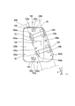
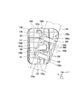
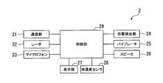
- FIG. 3 is an exploded perspective view of the electronic device according to the embodiment of the present invention seen from the front side, showing a state in which a cover and a base are removed. It is the perspective view which looked at the cover of the electronic equipment, the inner lid, and the case concerning the embodiment of the present invention from the front side. It is the perspective view which looked at the cover of the electronic equipment, the inner lid, and the case concerning the embodiment of the present invention from the back side. It is the perspective view which looked at the cover of the electronic equipment concerning the embodiment of the present invention, the inner lid, and the case from the lower side.
- FIG. 6 is a perspective view showing an example of mounting the backpack of the electronic device according to the embodiment of the present invention on the left shoulder belt.
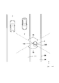
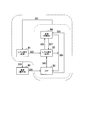
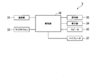
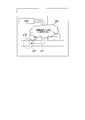
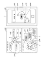
- FIG. 1 is a plan view of an example of a detection range of a front radar and a rear radar when an electronic device according to an embodiment of the present invention is arranged around a left shoulder of a wearer, as viewed from the positive side (upper side) in the Z-axis direction. is there. It is a figure which shows the operation example of the display part of the electronic device which concerns on embodiment of this invention. It is a figure which shows the structural example of the information communication system which concerns on embodiment of this invention. It is a figure which shows the example of a usage scene of the information communication system which concerns on embodiment of this invention. It is a block diagram which shows the structural example of the 1st portable terminal which concerns on embodiment of this invention.
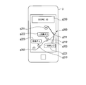
- 9 is an image example of information including a score displayed on the display unit of the second mobile terminal according to the embodiment of the present invention.
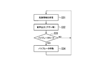
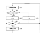
- It is a flow chart of an example of a processing procedure of a motion analysis method of temporary stop in a predetermined position concerning an embodiment of the present invention.
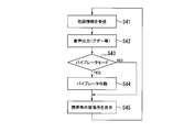
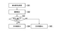
- It is a flow chart of an example of a processing procedure of a motion analysis method of left and right confirmation in a predetermined position concerning an embodiment of the present invention.
- the electronic device according to the present embodiment is used, for example, as a mobile terminal (first mobile terminal 2) included in an information communication system 1 described later.
- the electronic device is installed, for example, on the body, clothes, or portable object of a carrier (a moving pedestrian or the like).
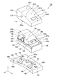
- FIG. 1 is a perspective view of an electronic device 100 according to an embodiment as viewed from the front side.
- FIG. 2 is an exploded perspective view of the electronic device 100 according to the embodiment as seen from the front side, and is a diagram showing a state in which the cover 101 and the base 109 are removed.
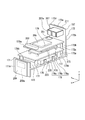
- 3, 4, and 5 are perspective views of the cover 101, the inner lid 103, and the case 105 of the electronic device 100 according to the embodiment, which are sequentially viewed from the front side, the rear side, and the lower side.
- the electronic device 100 includes, for example, a cover 101, an inner lid 103, a case 105, a frame 107, and a base 109.
- the structure 100a including the cover 101, the inner lid 103, and the case 105 constitutes a housing in which a space for housing the frame 107 and electronic components is formed.
- the X-axis, Y-axis, and Z-axis directions that are orthogonal to each other in the three-dimensional space are directions parallel to the respective axes.
- the X-axis direction is parallel to the front-back direction of the electronic device 100
- the positive X-axis direction is parallel to the direction from the rear portion RE of the structure 100a to the front portion FR, for example.
- the Y-axis direction is parallel to the left-right direction of the electronic device 100
- the positive direction of the Y-axis direction is parallel to the direction from the left side portion LS to the right side portion RS of the structure 100a, for example.
- the Z-axis direction is parallel to the vertical direction of the electronic device 100, and the positive Z-axis direction is parallel to the direction from the lower LP to the upper UP of the structure 100a, for example.
- the front-rear direction, the left-right direction, and the up-down direction of the electronic device 100 are the same as the front-rear direction, the left-right direction, and the up-down direction of the wearer.
- the surface of the upper portion UP is the upper surface UPS
- the surface of the lower portion LP is the lower surface LPS
- the surface of the left side portion LS is the left side surface LSS
- the surface of the right side portion RS is the right side surface RSS.
- the surface of the rear portion RE is the rear side surface RES
- the surface of the front portion FR is the front side surface FRS.
- the outer shape of the structure 100a is formed such that the vertical length LF at the front end of the front portion FR is shorter than the vertical length LR at the rear end of the rear portion RE. .. Further, the outer shape of the structure 100a is formed such that the maximum length L1 in the front-rear direction is longer than the maximum length L2 in the vertical direction. Further, regarding the outer shape of the structure 100a, the height position of the highest portion HF in the vertical direction (vertical direction) at the front end of the front portion FR is the height of the highest portion HR in the vertical direction (vertical direction) at the rear end of the rear portion RE. It is formed to be lower than the position,
- the outer shape of the cover 101 is formed, for example, in a curved shape so as to bulge in the positive direction along the Z-axis (that is, above the electronic device 100 in the vertical direction).
- the outer shape of the cover 101 moves from the rear portion 101a (or the rear portion RE) toward the front portion 101b (or the front portion FR) in the positive direction of the X-axis direction (that is, the front-rear direction of the electronic device 100), It is formed in a shape in which the distance between the reference position and the tip position in the positive Z-axis direction changes in a decreasing tendency.
- the reference position is, for example, the lowest end position of the lower end edge portion 112 described later.
- the tip position is, for example, a position on the surface (outer surface) 101A described later. That is, the outer shape of the cover 101 is formed in a shape in which the tip position in the positive Z-axis direction changes in a downward trend as it goes from the rear portion 101a to the front portion 101b in the positive X-axis direction, that is, a so-called front-down shape.
- the outer shape of the cover 101 is, for example, when the electronic device 100 is arranged around the shoulder of the wearer while making the front-back direction of the electronic device 100 parallel to the front-back direction of the wearer, the cover 101 is placed on the cheek of the wearer. The shape is formed so as not to interfere with the movement of the wearer's face.
- the front-back direction of the wearer is, for example, parallel to the moving direction of the wearer.
- the cover 101 is formed of, for example, a material such as resin having a high electromagnetic wave transparency.
- the cover 101 is attached to the case 105 so as to cover an inner lid 103 described later.
- the cover 101 and the inner lid 103 are integrally joined by, for example, a cushioning material having an adhesive portion adhered to each other.
- the rear portion 101a of the cover 101 is formed with a notch portion 111 for the inner lid, which exposes a radar transmitting portion 121 of the inner lid 103, which will be described later.
- the cover 101 includes a plurality of claw portions 113 that protrude inward from the back surface (inner surface) 101B of the lower portion 101c.
- the claw portion 113 is inserted into a recess 156 formed in the cover fixing portion 155 of the case 105, which will be described later, and meshes with the cover fixing portion 155 to fix the cover 101 and the case 105 to each other.
- a front surface (outer surface) 101A of the front portion 101b of the cover 101 is provided with a display recess 114 in which a light guide 227 of a display unit 217, which will be described later, is arranged.
- Two display through-holes 115 that expose the two display-side end portions 227a of the light guide 227 to the outside are formed on the bottom surface of the display recess 114.
- the two display through holes 115 are, for example, at the same height position in the positive direction of the Z-axis direction, in the Y-axis direction (that is, in the left-right direction of the electronic device 100) on the front surface 101A of the front portion 101b of the cover 101. They are formed side by side at a predetermined interval in the Y-axis direction so as to straddle over.
- the cover 101 On the surface 101A of the right side portion 101d of the cover 101, an operation through hole 116 into which a push button 231 of the operation portion 221 described later is inserted is formed.
- the cover 101 is provided with a mounting seat 117 to which a button support portion 233 of an operation portion 221 described later is attached, in the vicinity of the operation through hole 116 on the back surface 101B of the upper portion 101e.
- the mounting seat 117 includes a boss 117a and a reinforcing rib 117b that project in the negative Z-axis direction, for example.
- the boss 117a is formed with a pin hole (not shown) into which the pin 233a protruding from the button support portion 233 is inserted.
- the cover 101 includes a plurality of ribs 118 protruding inward from the back surface 101B of the right side portion 101d and the left side portion 101f and extending in the Z-axis direction.
- the rib 118 provided near the operation through hole 116 is arranged side by side in the operation through hole 116 in the X-axis direction.
- the outer shape of the inner lid 103 is curved so as to bulge in the positive direction along the Z-axis, and the Z-direction increases from the rear portion 103a toward the front portion 103b along the positive X-axis direction. It is formed in a shape in which the tip position in the positive axial direction changes in a downward tendency, that is, a so-called front-down shape.
- the inner lid 103 is formed of, for example, a material such as a resin having a high electromagnetic wave permeability.
- the inner lid 103 includes a radar transmission unit 121 on the rear portion 103a.
- the radar transmission part 121 of the inner lid 103 is provided at a position relatively higher in the positive direction of the Z-axis direction than the radar transmission part 151 of the case 105 described later by a predetermined distance.
- the radar transmission section 121 is provided so as to face a radiation surface 211a of a rear radar 211 described later.
- the inner lid 103 is attached to the case 105 so as to close an opening 153a formed by a support wall portion 153 of the case 105 described later.
- the radar transmission part 121 provided on the rear portion 103a of the inner lid 103 is exposed to the outside through the inner lid cutout portion 111 of the cover 101.
- a portion of the surface (outer surface) 103A of the inner lid 103 other than the radar transmission portion 121 is covered by the cover 101 so as to be shielded from the outside.
- the lower end edge portion 122 of the lower portion 103c of the inner lid 103 is inserted into a seal groove 154 of a support wall portion 153 of the case 105, which will be described later, via a seal material (not shown) over the entire circumference, and the support wall portion 153 is formed.
- the inner space of the inner lid 103 and the case 105 is sealed by being fitted into.
- the inner lid 103 is provided with a flange portion 123 projecting outward in the Y-axis direction near the lower end edge portion 122 of the surface 103A of the right side portion 103d and the left side portion 103e.
- the flange portion 123 is formed with a screw through hole 124 which is continuous with a screw hole (not shown) of an inner lid boss 158 which will be described later.
- the flange portion 123 is fixed to the inner lid boss 158 by screwing a screw (not shown) inserted into the screw through hole 124 and the screw hole of the inner lid boss 158 into the inner lid boss 158.
- a notch 125 for the case is formed in the flange 123, through which the cover fixing portion 155 of the case 105 is inserted toward the claw portion 113 of the cover 101.
- the inner lid 103 is provided with a claw portion 126 protruding outward in the X-axis direction below the radar transmission portion 121 on the surface 103A of the rear portion 103a.
- the claw portion 126 is inserted into a recess 157 formed on the back surface (inner surface) 105B of the case 105 described later, and engages with the case 105 to fix the inner lid 103 and the case 105 to each other.
- the inner lid 103 includes a plurality of case fixing portions 127 on the back surface (inner surface) 103B.
- the outer shape of the case fixing portion 127 is formed, for example, in a plate shape that protrudes toward the case 105 in the negative direction of the Z-axis direction from the lower end edge 122 of the lower portion 103c.
- a through hole 128 penetrating in the Y-axis direction is formed at the tip of the case fixing portion 127 in the protruding direction.
- the claw portion 159 provided on the back surface 153B of the supporting wall portion 153 of the case 105 which will be described later, is inserted into the through hole 128 and meshes with the case fixing portion 127, whereby the inner lid 103 and the case. 105 are fixed to each other.
- a front surface 103A of the front portion 103b of the inner lid 103 is provided with a support recess 129 to which a light guide 227 of a display unit 217 to be described later is mounted.
- the light guide 227 of the display unit 217 is bonded to the bottom surface of the support recess 129 with, for example, an adhesive.
- On the bottom surface of the support recess 129 a light source through hole 130 is formed through which the light source side end 227b of the light guide 227 is inserted toward the inside.
- the inner lid 103 includes a light source mounting seat 131 to which a light source 229 of the display unit 217, which will be described later, is mounted on the back surface 103B of the front portion 103b.
- the light source mounting seat 131 includes, for example, a boss 131a and a reinforcing rib 131b that project in the negative Z-axis direction.
- a screw hole (not shown) into which a screw (not shown) for fixing the light source 229 is inserted is formed in the boss 131a.
- the inner lid 103 On the surface 103A of the right side portion 103d of the inner lid 103, there is formed a button through hole 132 into which a connecting member (not shown) of a push button 231 of the operation portion 221 to be described later is inserted.
- the inner lid 103 includes, on the surface 103A of the right side portion 103d, below the button through hole 132, a reinforcing rib 133 that projects outward in the Y-axis direction and extends in the Z-axis direction up to the flange 123.
- a support portion recess 134 in which a button support portion 233 of the operation portion 221 to be described later is arranged is formed.
- the inner lid 103 includes a switch mounting seat 135 to which a switch body 235 of the operation unit 221 described later is mounted, in the vicinity of the button through hole 132 on the back surface 103B on the right side portion 103d.
- the switch mounting seat 135 includes a boss 135a that projects in the negative Z-axis direction, for example.
- a screw hole (not shown) into which a screw (not shown) for fixing the switch body 235 is inserted is formed in the boss 135a.
- a plurality of speaker through holes 136 facing a speaker 215 to be described later are formed behind the button through hole 132 on the surface 103A of the right side portion 103d of the inner lid 103.
- the inner lid 103 includes a speaker mounting seat 137 to which a speaker 215 to be described later is mounted, in the vicinity of the plurality of speaker through holes 136 on the back surface 103B on the right side portion 103d.
- the speaker mounting seat 137 includes, for example, a boss 137a and a reinforcing rib 137b that project in the negative Z-axis direction.
- a screw hole (not shown) into which a screw (not shown) for fixing the speaker 215 is inserted is formed in the boss 137a.
- the inner lid 103 includes a waterproof member (not shown) that covers the plurality of speaker through holes 136 on the back surface 103B of the inner lid 103.
- a surface 103A of the upper portion 103f of the inner lid 103 has a microphone through hole 138 facing a microphone 213 described later.
- the inner lid 103 is provided with a microphone mounting seat 139 to which a microphone 213 described later is mounted in the vicinity of the microphone through hole 138 on the back surface 103B of the upper portion 103f.
- the microphone mounting seat 139 includes, for example, a boss 139a and a reinforcing rib 139b that project in the negative Z-axis direction.
- a screw hole (not shown) into which a screw (not shown) for fixing the microphone 213 is inserted is formed in the boss 139a.
- the inner lid 103 includes a waterproof member (not shown) that covers the microphone through hole 138 on the back surface 103B of the inner lid 103.
- the inner lid 103 includes a plurality of ribs 140 protruding inward from the back surface 103B and extending in the Z-axis direction.
- the outer shape of the case 105 is formed in a box shape, for example.
- the case 105 is made of, for example, a material such as resin having a high electromagnetic wave permeability.
- the case 105 includes a radar transmission unit 151 on the front portion 105a.
- the radar transmission part 151 of the case 105 is provided at a position relatively lower than the radar transmission part 121 of the inner lid 103 by a predetermined distance in the positive direction of the Z-axis direction.
- the radar transmission unit 151 is provided so as to face a radiation surface 209a of the front radar 209 described later.
- the case 105 has an upper edge portion 152 on which the cover 101 is mounted on the upper portion 105b.
- the outer shape of the upper end edge portion 152 is formed in a stepped shape that fits with the lower end edge portion 112 of the cover 101, for example.
- the upper end edge portion 152 of the case 105 and the lower end edge portion 112 of the cover 101 are joined by a so-called imprint type fitting.
- the upper edge portion 152 includes, for example, an outer end portion 152a and an inner end portion 152b that protrudes one step further than the outer end portion 152a in the positive Z-axis direction.
- the lower edge 112 of the cover 101 is brought into contact with the outer edge 152a of the upper edge 152 in the Z-axis direction to smoothly connect the surface 101A of the cover 101 and the surface (outer surface) 105A of the case 105.
- the case 105 includes a support wall portion 153 in which the inner lid 103 is mounted.
- the inner lid 103 attached to the support wall portion 153 closes the opening 153 a formed by the support wall portion 153.
- the support wall portion 153 is integrally connected to the back surface (inner surface) 105B at the front portion 105a and the rear portion 105c of the case 105, and is provided more inwardly than the back surface 105B at the left side portion 105d and the right side portion 105e. .
- a seal groove 154 into which the seal material (not shown) and the lower end edge 122 of the inner lid 103 are inserted is formed in the support wall portion 153.
- the lower end edge portion 122 of the inner lid 103 is abutted against a sealing material (not shown) in the seal groove 154 in the Z-axis direction to seal between the inner wall surface forming the seal groove 154 and the lower end edge portion 122. To do.
- the case 105 includes a plurality of cover fixing portions 155 on the back surface 105B.
- the outer shape of the cover fixing portion 155 is formed, for example, in a plate shape that protrudes toward the cover 101 in the positive Z-axis direction from the upper end edge portion 152.
- a concave portion 156 that is recessed inward from the outside in the Y-axis direction is formed at the tip of the cover fixing portion 155 in the protruding direction.
- the cover fixing portion 155 fixes the cover 101 and the case 105 to each other by inserting the claw portion 113 provided on the back surface 101B of the cover 101 into the recess 156 and engaging with the cover fixing portion 155.
- a recess 157 that is recessed in the negative direction along the X-axis is formed.
- the case 105 and the inner lid 103 are fixed to each other by inserting the claw portion 126 provided on the surface 103A of the rear portion 103a of the inner lid 103 into the recess 157 and engaging with the case 105.
- the case 105 includes a plurality of inner lid bosses 158 extending in the positive Z-axis direction on the surface (outer surface) 153A of the support wall portion 153.
- the inner lid boss 158 is formed with a screw hole into which a screw (not shown) for fixing the flange portion 123 of the inner lid 103 is inserted.
- the case 105 includes a plurality of claws 159 protruding inward on the back surface (inner surface) 153B of the support wall portion 153.
- the claw portion 159 is inserted into the through hole 128 formed in the case fixing portion 127 of the inner lid 103 and meshes with the case fixing portion 127 to fix the case 105 and the inner lid 103 to each other.
- the case 105 includes a plurality of frame mounting seats 160 to which a frame 107 described later is mounted on the back surface 105B of the lower portion 105f.
- the frame attachment seat 160 includes a boss 160a that projects in the positive Z-axis direction, for example.
- the boss 160a is formed with a screw hole into which a screw (not shown) for fixing the frame 107 is inserted.
- the outer shape of the lower portion 105f of the case 105 is formed in a shape that is convexly curved in the positive Z-axis direction when viewed from the Y-axis direction, for example.
- the front surface 105A and the back surface 105B of the lower portion 105f are formed into curved surfaces that are convexly curved in the positive Z-axis direction.
- the case 105 includes a device mounting seat 161 to which a vibrating device 219, which will be described later, is mounted, at a position displaced from the central portion toward the right side portion 105e on the back surface 105B of the lower portion 105f.
- the device mounting seat 161 includes, for example, a boss 161a.
- the case 105 includes a device accommodating portion 162 that accommodates a vibrating device 219, which will be described later, at a position displaced from the central portion of the lower portion 105f toward the right side portion 105e.
- the device accommodating portion 162 is formed so as to be arranged at a position avoiding the highest portion (highest portion) 105U in the positive direction in the Z-axis direction on the surface 105A of the lower portion 105f. There is.
- the position avoiding the highest portion 105U is, for example, a position in front of the highest portion 105U.
- the outer shape of the device accommodating portion 162 is formed, for example, in a shape forming a part of a hollow cylinder.
- a part of the front surface 105A (corresponding to the lower surface LPS of the structure 100a) in the lower portion 105f is swollen in the negative Z-axis direction
- the back surface 105B in the lower portion 105f is in the Z-axis direction. It is provided so as to be recessed in the negative direction.
- the device accommodating portion 162 is inserted into a device through hole 185 formed in the base 109, which will be described later, and protrudes in the negative Z-axis direction from the base 109. Accordingly, when the base 109 described later is attached to the left shoulder belt 181 of the backpack 180, the device housing 162 directly contacts the left shoulder belt 181 and transmits the vibration of the vibration device 219. .
- a connector through hole 163 into which an interface connector 241a described later is inserted is formed in the vicinity of the lower portion 105f of the front surface 105A of the rear portion 105c of the case 105.
- the case 105 includes a board mounting seat 164 for mounting an interface board 241b, which will be described later, in the vicinity of the connector through hole 163 on the rear portion 105c side of the back surface 105B of the lower portion 105f.
- the board mounting seat 164 includes, for example, a boss 164a protruding in the positive Z-axis direction.
- the boss 164a is formed with a screw hole (not shown) into which a screw (not shown) for fixing the interface board 241b is inserted.
- the case 105 includes a claw mounting portion 165 near a front portion 105a of the surface 105A of the lower portion 105f, in which a claw portion 183 of the base 109 described later is engaged (stopped in engagement).
- the case 105 includes a fixing mechanism 166 that is fixed to a case fixing member 184 of the base 109, which will be described later, in the vicinity of the rear portion 105c of the surface 105A of the lower portion 105f.
- the fixing mechanism 166 includes an operation lever 166a and a base fixing member 166b which are integrally formed.
- the operation lever 166a fixes and fixes the base fixing member 166b with respect to the case fixing member 184 by operating the sliding movement of the base fixing member 166b in a through hole 184a formed near the case fixing member 184 described later, for example. Operate the release.
- the base fixing member 166b is provided so as to project from the surface 105A of the lower portion 105f of the case 105, for example, and is inserted into a through hole 184a of the case fixing member 184 described later.
- the base fixing member 166b slides in the through hole 184a to perform fixing by meshing with the case fixing member 184 and release by fixing the meshing.
- the case 105 and the base 109 are fixed to each other by the claw portion 183 engaging with the claw mounting portion 165 and the base fixing member 166b of the fixing mechanism 166 meshing with the case fixing member 184.
- FIG. 6 is a diagram in which a part of the electronic device 100 according to the embodiment is broken and viewed from the negative side to the positive side (left side to right side) in the Y-axis direction.
- FIG. 7 is a perspective view of the frame 107 of the electronic device 100 according to the embodiment as viewed from the positive side (front side) in the X-axis direction.
- FIG. 8 is a perspective view of the frame 107 of the electronic device 100 according to the embodiment as viewed from the negative side (rear side) in the X-axis direction.
- the outer shape of the frame 107 is formed into a plate shape of, for example, a front T-shape and a rear L-shape.
- the frame 107 is made of a material such as an electrically insulating resin.
- the frame 107 includes a front side support part 171, a rear side support part 172, a left side support part 173, a right side support part 174, and a connection part 175.
- the front side support part 171 and the rear side support part 172, and the left side support part 173 and the right side support part 174 are integrally formed.
- the left side support portion 173 and the right side support portion 174 are integrally formed with a connection portion 175 arranged near the front side support portion 171.
- the outer shape of the front support portion 171 is formed, for example, in a rectangular frame plate shape having a through hole.
- the front support portion 171 is arranged, for example, such that the front surface 171A is parallel to the YZ plane defined by the Y axis and the Z axis.
- the front support portion 171 supports a front radar 209, which will be described later, on the front surface 171A, for example, via a metal shield member (not shown).
- the front radar 209 is fixed to the front surface 171A by, for example, a screw (not shown) attached to the front support portion 171.
- the front support portion 171 makes the electromagnetic wave radiation surface 209a of the front radar 209 face the radar transmission portion 151 of the case 105.
- the radiation surface 209a emits an electromagnetic wave (transmitted wave) toward the outside and receives an electromagnetic wave from the outside (a reflected wave generated when the transmitted wave is reflected by an external object). .
- the electromagnetic wave emitted from the front radar 209 passes through the radar transmission section 151 of the case 105 and is radiated in front of the electronic device 100.
- a reflected wave generated by a transmitted wave being reflected by an external object in front of the electronic device 100 is transmitted through the radar transmission unit 151 of the case 105 and received by the front radar 209.
- the outer shape of the rear support portion 172 is formed, for example, in the shape of a gate plate.
- the rear support part 172 includes a guide part 172a extending in the Y-axis direction, and a pair of leg parts 172b extending from both ends of the guide part 172a in the Y-axis direction in the negative direction of the Z-axis direction.
- the rear side support portion 172 is arranged, for example, such that the rear surface 172A is parallel to the YZ plane defined by the Y axis and the Z axis.
- the rear side support part 172 is provided with a reinforcing rib 172c that protrudes in the positive direction of the X-axis direction and extends in the Z-axis direction on the back surface (that is, the front surface) 172B of the pair of leg portions 172b.
- the rear side support portion 172 supports a rear radar 211, which will be described later, on the front surface 172A via, for example, a metal shield member (not shown).
- the rear radar 211 is fixed to the front surface 172A by a screw (not shown) attached to the rear support 172, for example.
- the rear support part 172 arranges the rear radar 211 at a position relatively higher than the front radar 209 of the front support part 171 by a predetermined distance in the positive direction of the Z-axis direction.
- the rear side support portion 172 makes the electromagnetic wave radiation surface 211 a of the rear radar 211 face the radar transmission portion 121 of the inner lid 103.
- the radiation surface 211a emits an electromagnetic wave (transmitted wave) toward the outside and receives an electromagnetic wave from the outside (a reflected wave generated by the transmitted wave being reflected by an external object). ..
- the electromagnetic wave emitted from the rear radar 211 passes through the radar transmission section 121 of the inner lid 103 and is emitted to the rear of the electronic device 100.
- a reflected wave generated by the transmission wave being reflected by an external object behind the electronic device 100 is transmitted through the radar transmission section 121 of the inner lid 103 and received by the rear radar 211.
- the rear support 172 supports a positioning signal receiving antenna 207, which will be described later, on the back surface 172B of the upper portion 172d via, for example, a metal shield case 207a.
- the positioning signal receiving antenna 207 is fixed to the rear support portion 172 by a screw (not shown) that attaches the shield case 207a to the back surface 172B of the rear support portion 172, for example.
- each of the left side support portion 173 and the right side support portion 174 is formed in a rectangular plate shape, for example.
- Each of the left side support portion 173 and the right side support portion 174 is arranged so that, for example, the upper surfaces 173A and 174A are parallel to the XY plane defined by the X axis and the Y axis.
- the left side support portion 173 and the right side support portion 174 are arranged at a predetermined interval in the Y-axis direction.
- the ends of the left side support portion 173 and the right side support portion 174 on the positive side in the X-axis direction are connected to the front side support portion 171.
- the negative side ends of the left support portion 173 and the right support portion 174 in the X-axis direction are connected to the pair of leg portions 172b of the rear support portion 172.
- the left side support portion 173 and the right side support portion 174 are provided with reinforcing ribs 173a and 174a on the respective surfaces 173A and 174A, which protrude in the positive Z-axis direction and extend in the X-axis direction.
- the reinforcing ribs 173a and 174a are formed integrally with the reinforcing rib 172c of the rear side support portion 172.
- the outer shapes of the reinforcing ribs 173a and 172c and the reinforcing ribs 173a and 172c are formed in, for example, an L-shaped plate shape.
- the left side support portion 173 and the right side support portion 174 are formed with a plurality of screw insertion holes (not shown) into which screws (not shown) attached to the plurality of frame mounting seats 160 of the case 105 are inserted in the Z-axis direction. ing.
- Surfaces 173A and 174A of the left support 173 and the right support 174 are reference planes that define relative positions of electronic components such as the communication antenna 203, the communication module 205, the battery 223, and the control unit 225, which will be described later.
- the left support portion 173 and the right support portion 174 are arranged, for example, below the midpoint MPZ in the Z-axis direction of the electronic device 100.
- the midpoint MPZ is, for example, a position in the Z-axis direction (vertical direction) corresponding to 1/2 of the maximum length L2 in the Z-axis direction (vertical direction) in the outer shape of the structure 100a of the electronic device 100.
- the left side support portion 173 and the right side support portion 174 support a battery 223 described below on the respective surfaces 173A and 174A.
- the left side support part 173 and the right side support part 174 include a plurality of battery fixing members 176 that protrude from the respective surfaces 173A and 174A in the positive Z-axis direction and sandwich the battery 223 from both sides in the Y-axis direction.
- the left support 173 and the right support 174 include a plurality of spacers 177 extending in the positive Z-axis direction on the respective surfaces 173A and 174A.
- the plurality of spacers 177 support the sub-board 178 arranged apart from the battery 223 in the positive Z-axis direction.
- the sub-board 178 includes, for example, a lower sub-board 178b and an upper sub-board 178c that are stacked in two layers in the Z-axis direction with a spacer 178a interposed therebetween.
- a control unit 225 described later is mounted on the sub-board 178.
- the sub-board 178 supports the main board 179 arranged apart from the sub-board 178 in the positive Z-axis direction by, for example, a plurality of spacers (not shown) extending in the positive Z-axis direction.
- the main board 179 is arranged at a position lower than a positioning signal receiving antenna 207, which will be described later, in the positive direction of the Z-axis direction, for example.
- a communication IC card 201, a communication antenna 203, and a communication module 205, which will be described later, are mounted on the main board 179.
- the main board 179 is provided with the communication antenna 203 at an end portion (that is, a front end portion) 179a farthest from the positioning signal receiving antenna 207 in the positive direction of the X-axis direction, for example.
- the sub-board 178 and the main board 179 are arranged between the front support 171 and the rear support 172 in the X-axis direction.
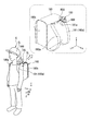
- FIG. 9 is a perspective view showing an example of mounting the backpack bag 180 of the electronic device 100 according to the embodiment on the left shoulder belt 181.
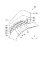
- FIG. 10 is a perspective view of the electronic device 100 according to the embodiment as viewed from the negative side (lower side) in the Z-axis direction.
- FIG. 11 is a plan view of the base 109 of the electronic device 100 according to the embodiment as viewed from the positive side (upper side) in the Z-axis direction.
- FIG. 12 is a plan view of the base 109 of the electronic device 100 according to the embodiment as viewed from the negative side (lower side) in the Z-axis direction.
- FIG. 10 is a perspective view of the electronic device 100 according to the embodiment as viewed from the negative side (lower side) in the Z-axis direction.
- FIG. 11 is a plan view of the base 109 of the electronic device 100 according to the embodiment as viewed from the positive side (upper side) in the Z-axis direction.
- FIG. 12 is a plan view of the base
- the outer shape of the base 109 is, for example, a trapezoidal plate shape that is convexly curved in the positive Z-axis direction when viewed from the Y-axis direction.
- the thickness of the base 109 is formed to change in an increasing tendency as it goes from the negative side to the positive side in the X-axis direction.
- the base 109 is fixed to the mounting target of the electronic device 100.
- the wearing target is, for example, the left shoulder belt 181 worn on the left shoulder of the wearer C (that is, the left shoulder and the vicinity of or around the shoulder) of the left and right shoulder belts 180a of the carrying bag 180 carried by the wearer.
- the backpack 180 includes, for example, left and right shoulder belts 180a and a housing portion 180b.
- Each of the left and right shoulder belts 180a has an end portion (for example, an end portion on the positive direction side in the Z axis direction and the X axis direction shown in FIG. 9 and an end portion on the negative direction side in the Z axis direction) shown in FIG. Etc.).
- Each of the left and right shoulder belts 180a of the backpack 180 crosses the facing direction of the wearer C when worn on the wearer C.
- the back-and-forth direction of the backpack 180 is the X-axis direction and the up-down direction is the Z-axis direction
- the left shoulder belt 181 is It is arranged along a direction (D-axis direction) parallel to an axis (D-axis) inclined by a predetermined acute angle ⁇ in the counterclockwise direction.
- the base 109 is fixed, for example, on the left shoulder belt 181 near the highest portion 181a in the positive Z-axis direction.
- the highest part 181a of the left shoulder belt 181 is, for example, a part above the highest part (highest part) CS in the left shoulder part SL of the wearer C.
- the electronic device 100 is held by the wearer C. It is located on the side of the road RW when viewed from above.
- the backpack 180 is, for example, a so-called school bag.
- the midpoint MPX in the X-axis direction of the electronic device 100 is located in front of the highest part (highest part) CS of the shoulder. Will be placed.
- the midpoint MPX is, for example, a position in the X-axis direction (front-back direction) corresponding to 1/2 of the maximum length L1 in the X-axis direction (front-back direction) in the outer shape of the structure 100a of the electronic device 100.
- a surface (upper surface) 109A on the positive side in the Z-axis direction of the base 109 is a case mounting portion 182a in which the case 105 is arranged, and a belt extension extending from the case mounting portion 182a so as to project in the positive direction in the Y-axis direction. And a portion 182b. That is, the base 109 is formed larger than the case 105 when viewed from the Z-axis direction.
- the surface 109A of the base 109 is, for example, smooth.
- the case mounting portion 182a is, for example, a rectangular area extending in the X-axis direction when viewed from the positive side in the Z-axis direction to the negative side.
- the belt expansion part 182b moves from the front part 109a of the base 109 to the rear part 109b in the negative direction of the X-axis direction when viewed from the positive direction side of the Z-axis direction to the negative direction side thereof. This is a region where the protruding length in the direction changes in an increasing tendency.
- the belt expansion part 182b is formed so as to protrude from the outer edge of the case 105 in an external view (that is, an external view or a top view) when the base 109 is viewed from the case 105 side.
- the belt expansion portion 182b overlaps with the left shoulder belt 181 of the backpack 180 virtually or transparently together with a part of the case mounting portion 182a when viewed from the positive side to the negative side in the Z-axis direction, for example. Is provided.
- the entire (or almost the whole) of the belt extension 182b is virtually or transparently seen when the base 109 is viewed from the case 105 side (that is, in an external view or a top view). It is formed at a position overlapping the left shoulder belt 181 of the backpack 180.
- the base 109 includes a claw portion 183 that is engaged (stopped in engagement) with the claw mounting portion 165 of the case 105 near the front portion 109a of the case mounting portion 182a.
- the claw portion 183 projects in the positive direction in the X-axis direction from the edge portion 183b with respect to the through hole 183a penetrating the base 109 in the Z-axis direction, for example.
- the base 109 includes a case fixing member 184 near the rear portion 109b of the case mounting portion 182a, to which the base fixing member 166b (see FIG. 5) of the fixing mechanism 166 of the case 105 is fixed.
- the case fixing member 184 is provided, for example, at the edge portion 184b with respect to the through hole 184a penetrating the base 109 in the Z-axis direction.
- the base fixing member 166b of the fixing mechanism 166 slides in response to the operation of the operation lever 166a while being inserted into the through hole 184a, so that the base fixing member 166b is fixed by meshing with the case fixing member 184 and is meshed. It releases and fixes it.
- the device through hole 185 in which the device accommodating portion 162 of the case 105 is inserted is inserted at a position displaced in the positive direction in the Y-axis direction (that is, rightward in the left-right direction) from the center of the case mounting portion 182a.
- the device through hole 185 includes a surface (upper surface) 109A on the positive side in the Z-axis direction (for example, the case 105 side of the electronic device 100) of the base 109 and a negative direction side in the Z-axis direction ( For example, it is formed so as to communicate with the back surface (lower surface) 109B of the left shoulder belt 181 side of the backpack 180.
- the device through-hole 185 is, for example, in a state where the case 105 is mounted on the base 109 and the base 109 is fixed to the left shoulder belt 181 of the backpack 180 as shown in FIG. 162 is formed so as to be arranged at a position avoiding the highest portion (highest portion) CS in the left shoulder portion SL of the wearer C.
- the position avoiding the highest part CS is, for example, a position in front of the highest part CS.
- the tip portion 162a in the projecting direction of the device housing portion 162 arranged in the device through hole 185 is on the negative side in the Z-axis direction with respect to the back surface 109B of the base 109 (for example, on the left shoulder belt 181 side of the backpack 180). ).
- the back surface (lower surface) 109B of the base 109 on the negative side in the Z-axis direction is a belt fixing portion 186a to which the left shoulder belt 181 of the backpack 180 is fixed, and the belt fixing portion 186a to the Y-axis.
- the belt fixing portion 186a is parallel to the axis (D axis) inclined by a predetermined acute angle ⁇ in the clockwise direction with respect to the X axis when viewed from the negative side to the positive side in the Z axis direction (D axis direction). ) Is a rectangular area extending to.
- the case expansion portion 186b moves in the negative direction in the Y-axis direction as it goes from the front portion 109a to the rear portion 109b of the base 109 in the D-axis direction when viewed from the negative side in the Z-axis direction to the positive side. This is a region where the protruding length changes in an increasing tendency.
- the case expansion portion 186b is virtually or transparently eclipsed from the outer edge of the left shoulder belt 181 in an external view (that is, an external view or a top view) of the left shoulder belt 181 to be worn from the base 109 side. It is formed so as to put out.
- case expansion portion 186b is provided so as to virtually or transparently overlap with the case 105 together with a part of the belt fixing portion 186a when viewed from the negative side to the positive side in the Z-axis direction, for example. ..
- the case expansion part 186b is virtually or transparently viewed from the base 109 side by looking at the left shoulder belt 181 which is the wearing target (that is, the external view or the top view), and the entire case expansion part 186b is seen. (Or almost the whole) is formed at a position overlapping with the case 105.
- the base 109 includes a plurality of ribs 187 provided by forming a plurality of recesses 187a on the back surface 109B, for example.
- the plurality of ribs 187 are formed so as to protrude from the bottom surface 187A of each recess 187a in the negative Z-axis direction and extend in the Y-axis direction and the X-axis direction.
- the base 109 includes two belt contact portions 188 that project in the negative direction of the Z-axis direction from the ribs 187 and extend in the D-axis direction in the belt fixing portion 186a.
- the two belt contact portions 188 are arranged at a predetermined interval in the direction orthogonal to the D axis direction.
- each belt contact portion 188 is formed smooth, for example.
- a plurality of through holes 188a penetrating in the Z-axis direction are formed in the two belt contact portions 188.
- the plurality of through holes 188a discharge liquid such as water existing on the front surface 109A side of the base 109 to the back surface 109B side.
- the base 109 has two belts at positions (eg, the front portion 109a and the rear portion 109b of the base 109) deviated from the central portion of the belt fixing portion 186a to both sides in the D-axis direction.
- Through hole 189 is formed.
- Each belt through hole 189 is formed so as to extend in a direction orthogonal to the D-axis direction.
- the two belt through holes 189 are arranged on both sides of the device through hole 185 in the D-axis direction.
- each belt through hole 189 on the surface 109A of the base 109 a strap recess 190 into which a fixing member 192b of the strap 192 to be described later is inserted is formed in the vicinity of the peripheral edge portion of the belt expansion portion 182b.
- the base 109 includes a strap mounting portion 191 on which a strap 192 to be described later is mounted, at a portion of the inner wall surface forming each belt through hole 189, which is separated from the strap recess 190 in the direction orthogonal to the D axis direction.
- the outer shape of the strap mounting portion 191 is formed, for example, in the belt through hole 189 in a plate shape extending in the D-axis direction.
- the outer shape of the strap 192 is formed in a band shape, for example.
- the width of the strap 192 is formed smaller than the width of the belt through hole 189 in the D-axis direction.
- the strap 192 includes a fixing member 192b attached to one end 192a in the longitudinal direction.
- the outer shape of the fixing member 192b is formed, for example, in a rod shape longer than the width of the strap 192.
- the fixing member 192b is fixed to the base 109 by inserting the protrusions protruding from both ends in the width direction of the strap 192 into the strap recesses 190 on the surface 109A of the base 109.
- the strap 192 is inserted through the belt through hole 189 toward the back surface 109B side of the base 109 with the fixing member 192b inserted in the strap recess 190 on the front surface 109A side of the base 109.
- the strap 192 is attached to the strap attaching portion 191 while being wound around the left shoulder belt 181 arranged on the back surface 109B of the base 109, so that the base 109 is restrained and fixed so as to be bound to the left shoulder belt 181. To do.
- Each of the left and right shoulder belts of the carrying bag 180 carried by the carrier C intersects with the facing direction of the carrier C, and the position and posture may change according to the physique of the carrier C. is there.
- the base 109 can be replaced with a plurality of different replacement bases 193 so as to suppress changes in the position and orientation of the case 105.
- the plurality of different replacement bases 193 are formed so that at least one of their sizes and shapes is different from each other.
- the plurality of different replacement bases 193 are formed such that the size and shape of the belt expansion portion 182b are different when viewed from the positive side to the negative side in the Z-axis direction.
- the plurality of different replacement bases 193 may be formed to have different thicknesses in the Z-axis direction, for example.
- FIG. 14 is a plan view of the two replacement bases 193 of the electronic device 100 according to the embodiment as viewed from the positive side (upper side) in the Z-axis direction.
- the two replacement bases 193a and 193b shown in FIG. 14 are formed such that the case mounting portion 182a is the same as the base 109, but the size and shape of the belt expansion portion 182b are different.
- the belt extension 182b of the replacement base 193a is formed smaller than the belt extension 182b of the base 109.
- the belt extension 182b of the replacement base 193a corresponds to the case where the inclination of the left shoulder belt 181 with respect to the positive direction of the X-axis is smaller than that of the base 109.
- the left shoulder belt 181 when viewed from the positive direction side to the negative direction side in the Z-axis direction, the left shoulder belt 181 is an axis tilted counterclockwise with respect to the X axis by a predetermined acute angle ⁇ a smaller than the predetermined acute angle ⁇ in the base 109 ( It is arranged along a direction (D axis direction) parallel to the D axis). Further, for example, the belt extension 182b of the replacement base 193b is formed larger than the belt extension 182b of the base 109. The belt expansion portion 182b of the replacement base 193b corresponds to the case where the inclination of the left shoulder belt 181 with respect to the positive X-axis direction is larger than that of the base 109.
- the left shoulder belt 181 when viewed from the positive direction side to the negative direction side in the Z-axis direction, the left shoulder belt 181 is inclined in the counterclockwise direction with respect to the X-axis by a predetermined acute angle ⁇ b larger than the predetermined acute angle ⁇ in the base 109 ( It is arranged along a direction (D axis direction) parallel to the D axis).
- the electronic device 100 includes a communication IC card 201 as an electronic component fixed to a structure 100a including a cover 101, an inner lid 103, a case 105, and a frame 107.
- a battery 223 and a control unit 225 is a control unit 225.
- the communication IC card 201 is arranged at the rear end portion 179b of the main board 179 supported by the frame 107.
- the communication IC card 201 stores unique identification information regarding wireless communication through the communication antenna 203.
- the communication antenna 203 is arranged at the front end portion 179a of the main board 179 supported by the frame 107. Thereby, the communication antenna 203 is arranged between the front radar 209 and the rear radar 211 in the positive direction of the X axis direction. Further, the communication antenna 203 is arranged away from other electronic components, and is arranged, for example, so that the other electronic components do not exist at least on the upper side in the positive direction of the Z-axis direction.
- the communication antenna 203 is a bidirectional wireless communication antenna compatible with various mobile communication system standards.
- the communication antenna 203 transmits and receives radio waves to and from base stations of various mobile communication systems, for example.
- the communication module 205 is arranged in the center of the main board 179 supported by the frame 107.
- the communication module 205 controls bidirectional wireless communication using the communication antenna 203.
- the communication module 205 includes a processor such as a CPU, a ROM (Read Only Memory) for storing programs, a RAM (Random Access Memory) for temporarily storing data, and an electronic circuit such as a timer. At least a part of the communication module 205 may be an integrated circuit such as an LSI (Large Scale Integration).
- the positioning signal receiving antenna 207 is housed in a metal shield case 207a, and is arranged on the back surface 172B of the guide portion 172a above the rear support portion 172 of the frame 107.
- the positioning signal receiving antenna 207 is arranged forward of the rear radar 211 and rearward of the communication antenna 203 in the positive direction of the X-axis direction.
- the positioning signal receiving antenna 207 and the communication antenna 203 are arranged so as not to overlap each other in the X-axis direction and further not to overlap each other when viewed from the positive side to the negative side in the Z-axis direction. ..
- the positioning signal receiving antenna 207 is arranged further than the position of the communication antenna 203 so that the position of the upper end of the positioning signal receiving antenna 207 is lower than the position of the upper end of the rear radar 211 in the positive direction of the Z-axis direction. Is also located in a high position. Further, the positioning signal receiving antenna 207 is arranged away from other electronic components, for example, such that the other electronic components are not present at least on the upper side in the positive direction of the Z-axis direction.
- the positioning signal receiving antenna 207 is an antenna that receives a positioning signal of a positioning system (for example, Global Navigation Satellite System: GNSS).
- the positioning signal receiving antenna 207 receives radio waves from, for example, an artificial satellite of the positioning system.
- the outer shape of the shield case 207a is, for example, a box shape opened in the positive Z-axis direction.
- the shield case 207a is arranged so as to surround the positioning signal receiving antenna 207 below the positioning signal receiving antenna 207 in the Z axis direction and laterally in the X axis direction and the Y axis direction.
- the shield case 207a is formed of a material (for example, metal) that does not easily transmit electromagnetic waves, and shields the positioning signal receiving antenna 207 from electromagnetic wave noise such as reflected waves from directions other than the positive Z-axis direction.
- the front radar 209 is arranged on the front surface 171A of the front side support portion 171 of the frame 107 via a metallic shield member (not shown).
- the rear radar 211 is arranged on the surface 172A of the rear side support portion 172 of the frame 107 via a metal shield member (not shown).
- the rear radar 211 is arranged in front of the front radar 209 in the positive direction of the X-axis, and at a position higher than that of the front radar 209 in the positive direction of the Z-axis. Further, the rear radar 211 is arranged at a position higher than the highest part (highest part) CS of the shoulder in the positive direction of the Z-axis direction when the electronic device 100 is arranged on the shoulder of the wearer C, for example. .
- the front radar 209 and the rear radar 211 are, for example, the same millimeter wave radar.
- the outer shapes of the front radar 209 and the rear radar 211 are each formed in a rectangular plate shape, for example.
- the front radar 209 and the rear radar 211 each include a planar antenna (not shown) such as a microstrip antenna and a radome (not shown).
- the shield members (not shown) of the radars 209 and 211 are formed of a material (for example, metal) through which electromagnetic waves are difficult to pass, and are, for example, reflected waves from the rear of the front radar 209 and front of the rear radar 211.
- the radars 209 and 211 are shielded against electromagnetic wave noise such as reflected waves.
- Each of the radars 209 and 211 emits an electromagnetic wave (transmitted wave) outward from the emission surfaces 209a and 211a on the surface of a radome (not shown), and a reflected wave generated by the transmitted wave being reflected by an external object.
- the external object is, for example, a moving body such as a vehicle and a pedestrian around the electronic device 100 and a non-moving body such as a structure.
- the front radar 209 detects a front object around the electronic device 100
- the rear radar 211 detects a rear object around the electronic device 100, for example, an object behind the front radar 209.
- the emission surface 209a of the front radar 209 is arranged so as to face the radar transmission section 121 of the case 105.
- the transmitted wave and the reflected wave of the front radar 209 are transmitted only through the radar transmission section 121 of the case 105 in the structure 100a.
- the emission surface 211a of the rear radar 211 is arranged so as to face the radar transmission section 121 of the inner lid 103.
- the transmitted wave and the reflected wave of the rear radar 211 are transmitted only through the radar transmission section 121 of the inner lid 103 of the structure 100a.
- each of the radars 209 and 211 Based on the transmitted wave and the reflected wave, each of the radars 209 and 211 outputs, to the control unit 225, which will be described later, detection signals relating to, for example, the distance, relative velocity, relative position, and azimuth with respect to an external object.
- the detection range SA (that is, the radiation range of electromagnetic waves) of the radars 209 and 211 is, for example, an angular range of 60° to the left and right and 20° to the vertical with respect to the central axis.
- FIG. 15 illustrates an example of the detection ranges SA of the front radar 209 and the rear radar 211 when the electronic device 100 according to the embodiment is arranged around the left shoulder SL of the wearer C (the upward direction of the Z-axis direction (upward)). It is the top view seen from the side. As shown in FIG.
- the microphone 213 is arranged on the microphone mounting seat 139 on the back surface 103B of the upper portion 103f of the inner lid 103.
- the microphone 213 outputs a signal obtained by collecting the sound to the control unit 225 described later.
- the speaker 215 is arranged on the speaker mounting seat 137 on the back surface 103B of the right side portion 103d of the inner lid 103.
- the speaker 215 when the electronic device 100 is arranged in the vicinity of the left shoulder of the wearer C, as shown in FIG. It is arranged at the position on the head side (that is, the positive side in the Y-axis direction).
- the speaker 215 converts a signal input from the control unit 225 described later into sound.
- the display unit 217 includes, for example, a light guide 227 and a light source 229.
- the light guide 227 is arranged in the support recess 129 of the front portion 103b of the inner lid 103.
- the light guide 227 has two display-side end portions 227a exposed to the outside from the two display through holes 115 in the front portion 101b of the cover 101.
- the two display-side end portions 227a are arranged side by side with a predetermined interval in the Y-axis direction (that is, the left-right direction of the electronic device 100).
- the light guide 227 has a light source side end portion 227 b protruding inward from the light source through hole 130 of the inner lid 103 and faces the light source 229.
- the light guide 227 guides the light of the light source 229 from the light source side end 227b to the two display side ends 227a.
- the light source 229 includes, for example, LEDs (light emitting diodes) that emit three colors of red, green, and blue, and a drive circuit.
- the light source 229 is arranged on the light source mounting seat 131 on the back surface 103B of the front portion 103b of the inner lid 103.
- the light source 229 causes the LED to emit light in response to a signal input to the drive circuit from the control unit 225 described later.
- FIG. 16 is a diagram illustrating an operation example of the display unit 217 of the electronic device 100 according to the embodiment.
- the display unit 217 can be switched to a plurality of different display states according to the state of the electronic device 100.
- the plurality of different display states are, for example, a level display (blinking) state B1, an off state B2, a level display (lighting) state B3, a blinking (operating) state B4, and a blinking (abnormal) state B5. is there.
- the level display (blinking) state B1 corresponds to the charge state of the electronic device 100 in a normal state (for example, a state in which various abnormalities have not been detected).
- the electronic device 100 is connected to an external device via an interface connector 241a described later, and the battery 223 is charged by a power supply for driving the external device.
- the display unit 217 emits light in a plurality of different colors according to the charge level corresponding to the remaining capacity of the battery 223, and is in a blinking state indicating that the battery 223 is being charged by the power supply for driving the external device.
- the plurality of different colors are, for example, light blue that indicates a high level that is a charging level that is equal to or higher than a predetermined high-side threshold, red that indicates a low level that is a charging level that is equal to or lower than a predetermined low-side threshold, and high-side threshold and low-side. Yellow indicating a middle level, which is a charge level between the threshold and the like.
- the off state B2 corresponds to the suspended or stopped state of the electronic device 100.
- the operation pause state of the electronic device 100 is a state in which an operation other than the predetermined operation is paused while allowing execution of a predetermined operation such as a detection operation by an acceleration sensor of the control unit 225 described later.
- the operation stopped state of the electronic device 100 is, for example, a state in which the remaining capacity of the battery 223 is insufficient. In this case, the display unit 217 is in the light emission stopped state.
- the level display (lit) state B3 corresponds to the operation standby state of the electronic device 100 in the normal state.
- the display unit 217 emits light in a plurality of different colors according to the charge level corresponding to the remaining capacity of the battery 223, and becomes the lighting state indicating that the electronic device 100 is in the operation standby state.
- the plurality of different colors are the same as those in the level display (blinking) state B1.
- the blinking (operating) state B4 corresponds to the operating state of the electronic device 100 in the normal state.
- the electronic device 100 operates the detection operation by the radars 209 and 211, for example.
- the display unit 217 emits light of a predetermined color and is in a blinking state.
- the predetermined color is a color different from each of the light emission colors of the level display (blinking) state B1, the level display (lighting) state B3, and the blinking (abnormal) state B5.
- the blinking (at the time of abnormality) state B5 corresponds to the abnormal state of the electronic device 100.
- the display unit 217 emits light of a predetermined color and is in a blinking state.
- the predetermined color is a color different from the light emission colors of the level display (blinking) state B1, the level display (lighting) state B3, and the blinking (operating) state B4.
- step S01 the electronic device 100 in a normal state (for example, a state in which various abnormalities are not detected) is charged when it is physically connected to an external device via an interface connector 241a described later. become. Along with this, the display unit 217 enters the level display (blinking) state B1.
- step S02 the electronic device 100 in the normal state shifts from the charging state to the operation standby state when the physical connection with the external device via the interface connector 241a described later is released. Along with this, the display unit 217 shifts from the level display (blinking) state B1 to the level display (lighting) state B3.
- step S03 the electronic device 100 located in the non-active area and in the operation pause state shifts to the operation standby state when the acceleration sensor of the control unit 225 described later detects an acceleration of a predetermined value or more.
- the display unit 217 shifts from the off state B2 to the level display (lighting) state B3.
- the inactive area is an area other than the active area preset on the map.
- the active area is an area that allows execution of all operations of electronic device 100.
- step S04 the electronic device 100 located in the active region and in the operation rest state shifts to the operating state when the acceleration sensor of the control unit 225, which will be described later, detects an acceleration of a predetermined value or more.
- the display unit 217 shifts from the off state B2 to the blinking (operating) state B4. Further, as shown in step S05, the electronic device 100 located in the inactive area and in the operation standby state is detected to be located in the active area based on the positioning signal received by the positioning signal receiving antenna 207. And, it shifts to the operating state. Along with this, the display unit 217 shifts from the level display (lighting) state B3 to the blinking (operating) state B4.
- step S06 the electronic device 100 in the operation standby state located in the inactive region and the electronic device 100 in the operating state located in the active region are in the operation stop state after the standing state for a predetermined time elapses. Transition to the state. Further, the electronic device 100 in the operation standby state located in the non-active area and the electronic device 100 in the operating state located in the active area transition to the operation stop state when the remaining capacity of the battery 223 is insufficient. Accordingly, the display unit 217 shifts from the level display (lighting) state B3 or the blinking (operating) state B4 to the off state B2. It should be noted that the electronic device 100 in the inactive state transitions to the inactive state when the remaining capacity of the battery 223 is insufficient.
- the display unit 217 maintains the off state B2. Further, as shown in step S07, when it is detected that the electronic device 100 in the active state located in the active area is located in the inactive area based on the positioning signal received by the positioning signal receiving antenna 207. , Shift to the operation standby state. Along with this, the display unit 217 shifts from the blinking (operating) state B4 to the level display (lighting) state B3.
- step S08 the electronic device 100 in the normal state transitions to the abnormal state when the occurrence of various abnormalities is detected by the control unit 225, which will be described later, in a state other than the operation stop state.
- the display unit 217 enters the blinking (at the time of abnormality) state B5.
- step S09 the electronic device 100 in the abnormal state shifts to the operation stop state when the remaining capacity of the battery 223 is insufficient. In this case, the display unit 217 shifts from the blinking (at the time of abnormality) state B5 to the off state B2.
- the display unit 217 may be, for example, a liquid crystal display device, an organic EL (electroluminescence) display device, an electronic ink display device, or the like.
- the vibrating device 219 is attached to the device mounting seat 161 at a position displaced from the central portion toward the right side portion 105e of the back surface 105B of the lower portion 105f of the case 105, and is attached to the case 105. Is accommodated in the device accommodating portion 162 protruding downward. As a result, the vibrating device 219 is arranged below the midpoint MPZ in the Z-axis direction of the electronic device 100 and at a position lower than the battery 223 in the positive Z-axis direction. Further, the vibration device 219 is arranged between the front radar 209 and the rear radar 211 in the X-axis direction.
- the vibration device 219 is, for example, a vibration motor.
- the vibrating device 219 generates vibration in response to a signal input from the control unit 225 described later, and vibrates at least a part of the electronic device 100.
- the vibrating device 219 may be, for example, a linear actuator or a piezo actuator.
- the operation unit 221 includes, for example, a push button 231, a button support unit 233, and a switch body 235.
- the push button 231 is supported by the button support portion 233 and arranged in the operation through hole 116 of the right side portion 101 d of the cover 101.
- the push button 231 faces the left side surface CL of the head of the wearer C in the electronic device 100 when the electronic device 100 is arranged near the left shoulder of the wearer C, as shown in FIG. 9, for example. It is arranged on the surface (right side surface RSS).
- the push button 231 is arranged behind the YZ plane that passes through the midpoint MPX of the electronic device 100 in the front-rear direction.
- the outer shape of the button support portion 233 is formed, for example, in a rectangular frame shape arranged so as to surround the push button 231.
- the button support portion 233 is arranged in the support portion recess 134 of the right side portion 103d of the inner lid 103.
- the button support portion 233 includes a pin 233a protruding in the positive Z-axis direction.
- the pin 233a is attached to the mounting seat 117 on the back surface 101B of the right side portion 101d of the cover 101.
- the push button 231 is connected to the switch body 235 via a connecting member (not shown).
- the outer shape of the connection member (not shown) is formed in a rod shape, for example, connected to the push button 231.
- a connection member (not shown) is inserted into the button through hole 132 of the right side portion 103 d of the inner lid 103 and connected to the switch body 235 inside the inner lid 103.
- the switch body 235 is arranged on the switch mounting seat 135 on the back surface 103B of the right side portion 103d of the inner lid 103.
- the switch body 235 outputs to the control unit 225, which will be described later, a signal that is transmitted via a connecting member (not shown) and that corresponds to the push-down operation of the push button 231.
- the battery 223 is arranged on the left side support portion 173 and the right side support portion 174 of the frame 107. As a result, the battery 223 is arranged between the front radar 209 and the rear radar 211 in the X-axis direction. Further, the battery 223 is arranged, for example, below the midpoint MPZ (or the center of gravity CG) in the Z-axis direction of the electronic device 100.
- the control unit 225 is arranged on the sub-board 178 supported by the frame 107. Thereby, the control unit 225 is arranged between the front radar 209 and the rear radar 211 in the X-axis direction.
- the control unit 225 includes, for example, an acceleration sensor, a high-voltage device, a software function unit, and the like.
- the high-voltage equipment includes, for example, an inverter that performs mutual conversion between DC power and AC power, and a voltage converter that increases or decreases voltage.
- the software function unit functions by executing a predetermined program by a processor such as a CPU (Central Processing Unit).
- the software function unit is an ECU (Electronic Control Unit) including a processor such as a CPU, a ROM (Read Only Memory) that stores programs, a RAM (Random Access Memory) that temporarily stores data, and an electronic circuit such as a timer. .. At least a part of the software function unit may be an integrated circuit such as an LSI (Large Scale Integration).
- the control unit 225 controls the operation of various electronic components mounted on the electronic device 100.
- an interface connector 241a and an interface board 241b are fixed to the structure 100a of the electronic device 100.
- the interface connector 241a is arranged in the connector through hole 163 in the lower portion 105f of the rear portion 105c of the case 105.
- the interface board 241b is arranged on the board mounting seat 164 on the rear portion 105c side of the back surface 105B of the lower portion 105f of the case 105.
- the interface connector 241a is an interface that physically connects an external device in accordance with an appropriate bus standard.
- the interface board 241b recognizes and controls an external device connected via the interface connector 241a.
- the interface board 241b controls the power supply to the battery 223 by the power supply for driving the external device, for example, when the external device is physically connected via the interface connector 241a.
- FIG. 17 is a diagram showing a configuration example of the information communication system 1 according to the present embodiment.
- the information communication system 1 includes a first mobile terminal 2 (first terminal), a second mobile terminal 3 (second terminal), a data center 4 (center), and a server 5.
- the first mobile terminal 2, the second mobile terminal 3, the data center 4, and the server 5 are connected to each other via a network 6.
- the network 6 is, for example, a mobile communication network.
- the mobile communication network is, for example, a fourth generation mobile communication network, a fifth generation mobile communication network, or the like.
- the network 6 includes base stations and the like.
- the first mobile terminal 2 is a terminal carried by a carrier (for example, a child such as a child) who is a watching target.
- the first mobile terminal 2 is a robot having a communication function.
- the first mobile terminal 2 transmits at least one of position information, same-group pedestrian information, surrounding pedestrian information, and vehicle information to the data center 4 via the network 6.
- the first mobile terminal 2 receives at least one of the traffic information, the message, and the emergency information transmitted by the data center 4 via the network 6.
- the configuration of the first mobile terminal 2 will be described later.
- the same group pedestrian information is, for example, the same group pedestrian information indicating the same group pedestrians who are attending school or attending school together.
- the surrounding pedestrian information is information indicating pedestrians walking around the carrier.
- the vehicle information is vehicle information on a walking road.
- the second mobile terminal 3 is a terminal carried by a guardian or the like of a carrier (eg, a child such as a child) to be monitored.
- the second mobile terminal 3 is, for example, a smartphone, a tablet terminal, a smart watch, or the like.
- the second mobile terminal 3 receives, via the network 6, the first mobile terminal position information regarding the position of the first mobile terminal 2 transmitted by the data center 4.
- the first mobile terminal position information is image information. The configuration of the second mobile terminal 3 will be described later.
- the data center 4 includes a communication unit 41, a control unit 42, a model storage unit 43, and a storage unit 44.
- the communication unit 41 outputs the position information, the same-group pedestrian information, the surrounding pedestrian information, the vehicle information, and the like received from the first mobile terminal 2 via the network 6 to the control unit 42.
- the communication unit 41 outputs disaster information, suspicious person information, emergency information, and the like received from the server 5 via the network 6 to the control unit 42.
- the communication unit 41 transmits the danger notification output by the control unit 42 to the first mobile terminal 2 via the network 6.
- the communication unit 41 transmits the traffic information, the message, the emergency information, and the like output by the control unit 42 to the first mobile terminal 2 via the network 6.
- the communication unit 41 transmits the first mobile terminal position information, the emergency notification, the voice message and the like output by the control unit 42 to the second mobile terminal 3 via the network 6. Further, the communication unit 41 receives a signal of the detection value of the acceleration sensor 28 from the first mobile terminal 2 and outputs the received signal to the control unit 42.
- the control unit 42 stores the position information received from the first mobile terminal 2 in the storage unit 44.
- the control unit 42 stores the suspicious person information received from the server 5 in the storage unit 44.
- the suspicious person information includes the position information and the appearance time of the suspicious person.
- the control unit 42 generates the movement trajectory of the carrier who carries the first mobile terminal 2 based on the position information and the map information stored in the storage unit 44.
- the control unit 42 generates, as the first mobile terminal position information, information in which the generated movement trajectory is combined with the map information.
- the control unit 42 outputs the generated first mobile terminal position information to the communication unit 41.
- the control unit 42 includes the position information and the vehicle information received from the first mobile terminal 2, the emergency information, the disaster information and the suspicious person information received from the server 5, the model information stored in the model storage unit 43, and the storage unit.
- the dangerous place is set based on the map information and the position information stored in 44, and information indicating the set dangerous place is stored in the storage unit 44. Note that the dangerous places are places where disasters occur, places where there are many traffic accidents, places where suspicious persons have appeared, and the like.
- the control unit 42 generates a danger notification based on the map information stored in the storage unit 44, the information indicating the dangerous place, and the received position information, and outputs the generated danger notification to the communication unit 41.
- the control unit 42 controls the position information and the vehicle information received from the first mobile terminal 2, the emergency information received from the server 5, the model information stored in the model storage unit 43, the map information and the position stored in the storage unit 44. At least one of traffic information, a message, and emergency information is generated based on the information.
- the message is a voice signal, and text information is converted into a voice signal by a known method using a language model or a dictionary.
- the control unit 42 outputs the generated traffic information, message and emergency information to the communication unit 41.
- the control unit 42 outputs the generated message as a voice message and the emergency information as an emergency notification to the communication unit 41.
- control unit 42 stores the first mobile terminal 2 carried by the carrier and the second mobile terminal 3 carried by the guardian in the storage unit 44 in association with each other based on the telephone number or the identification information of the mobile terminal. Let As a result, the data center 4 performs processing on the plurality of sets of the first mobile terminal 2 and the second mobile terminal 3.
- the model storage unit 43 stores a statistical area traffic model, a traffic prediction model, and the like as model information.
- the statistical area traffic model is a model that statistically shows traffic conditions in the area, and the data center 4 obtains data relating to map information or traffic information from mobile terminals or the like, and statistically shows traffic information in each area. It is the model shown.
- the traffic prediction model is a model for predicting the traffic volume and the like in the corresponding area over the future from the traffic situation in each area accumulated in the past, and may be determined based on the data from the statistical area traffic model.
- the traffic prediction model may be the traffic volume at the time of going to and from school on the route of going and going to and from the carrier who carries the first mobile terminal 2.
- the storage unit 44 stores map information.
- the map information includes, for example, a map including a school road from home to school, location information of stores (for example, supermarkets, bookstores, stationery stores, etc.) on which the mobile person detours, and location information of cram schools etc. that go before returning home. Including and In addition, the map information includes information such as a sidewalk and a route network of roads (points and branches).
- the storage unit 44 also stores the position information of the first mobile terminal 2.
- the storage unit 44 stores information indicating a dangerous place and suspicious person information.
- the storage unit 44 stores a predetermined value used when generating the danger information.
- the server 5 is installed in, for example, a school or a ward office.
- the server 5 transmits disaster information regarding natural disasters such as earthquakes and typhoons and suspicious person information to the data center 4 via the network 6.
- the data center 4 may acquire these pieces of information by communicating with the server 5.
- FIG. 18 is a diagram showing an example of a usage scene of the information communication system 1 according to the present embodiment.
- the first mobile terminal 2 is used by being attached to, for example, a shoulder belt of a school bag.
- the first mobile terminal 2 acquires and transmits, for example, a voice uttered by a child carrying the first mobile terminal 2.
- the first mobile terminal 2 receives the information and message transmitted by the data center 4 and reproduces and notifies them.
- a school bag is an example of a carrying item, a shoulder bag, and a backpack.
- the data center 4 transmits to the first mobile terminal 2 the traffic information, the message and the emergency information generated based on the information received from the first mobile terminal 2 and the information received from the server 5. Further, the data center 4 transmits to the second mobile terminal 3 the first mobile terminal location information, the emergency notification and the voice message, which are generated based on the information received from the first mobile terminal 2 and the information received from the server 5. To do. It should be noted that, for example, when another child has another first mobile terminal 2 at the time of commuting to and from school, the data center 4 captures real-time information (for example, the current position, the same position, etc.) captured by the plurality of first mobile terminals 2. Group pedestrian information, surrounding pedestrian information, vehicle information, etc.) may be mutually used to generate the second information or the fourth information.
- the second mobile terminal 3 receives the first mobile terminal position information including the map information including the route that the child carrying the first mobile terminal 2 is walking from the data center 4, and the received first mobile terminal position information. Is displayed as status information.
- the second mobile terminal 3 also receives the emergency notification and the voice message transmitted by the data center 4, and displays or reproduces the received emergency notification or the voice message. The image displayed on the second mobile terminal 3 will be described later.
- the server 5 transmits, for example, broadcast contents by disaster prevention administrative radio to the data center 4 via the network 6.
- the usage scene shown in FIG. 18 is an example, and the usage scene is not limited to this.
- FIG. 19 is a block diagram showing a configuration example of the first mobile terminal 2 according to the present embodiment.
- the first mobile terminal 2 includes a communication unit 21, a radar 22, a microphone 23, a position detection unit 24, a vibrator 25, a speaker 26, a display unit 27, an acceleration sensor 28, and a control unit 29.
- the first mobile terminal 2 includes the operation unit 221 described above.
- the communication unit 21 includes the above-described communication IC card 201, communication antenna 203, and communication module 205.
- the communication unit 21 transmits the information output by the control unit 29 (for example, position information, pedestrian information in the same group, pedestrian information in the vicinity, and vehicle information) to the data center 4 via the network 6.
- the communication unit 21 receives information (for example, traffic information, message and emergency information) transmitted by the data center 4 and outputs the received information (for example, traffic information, message and emergency information) to the control unit 29.
- the communication unit 21 receives the danger information transmitted by the data center 4 and outputs the received danger information to the control unit 29.
- the radar 22 includes the front radar 209 and the rear radar 211 described above.
- the microphone 23 is the same as the microphone 213 described above.
- the microphone 23 outputs a signal (for example, a voice signal) obtained by collecting sound to the control unit 29.
- the microphone 23 may be a microphone array including a plurality of microphones.
- the position detector 24 includes the positioning signal receiving antenna 207 described above. The position detector 24 outputs the received positioning signal to the controller 29.
- the first mobile terminal 2 may acquire the information indicating the current position based on, for example, communication with the base station.
- the vibrator 25 includes the above-described vibration device 219, and generates vibration according to the notification information output by the control unit 29.
- the speaker 26 is the same as the speaker 215 described above.
- the speaker 26 converts a signal (for example, a voice signal) output by the control unit 29 into a sound.
- the display unit 27 is the same as the display unit 217 described above.
- the display unit 27 operates according to the notification information output by the control unit 29.
- the acceleration sensor 28 detects the acceleration of the first mobile terminal 2 in the three directions of the X axis, the Y axis, and the Z axis, and outputs a signal of the detected acceleration.
- the control unit 29 includes the control unit 225 described above.
- the control unit 29 acquires the detection signal output by the radar 22.
- the control unit 29 acquires the audio signal output by the microphone 23.
- the control unit 29 acquires the positioning information output by the position detection unit 24.
- the control unit 29 acquires the danger information output by the communication unit 21.
- the control unit 29 outputs the position information based on the positioning information acquired from the position detection unit 24 to the communication unit 21.
- the control unit 29 determines whether or not a person is included from the detection signal acquired from the radar 22, for example, using a known recognition method. When the detection signal includes a person, the control unit 29 sets the detection signal as the same group pedestrian information or the surrounding pedestrian information, and outputs the same group pedestrian information or the surrounding pedestrian information to the communication unit 21.
- control unit 29 determines that the pedestrian is a surrounding pedestrian when the size of the person included in the detection signal is less than the threshold, and determines the pedestrian in the same group when the size of the person is equal to or larger than the threshold. Further, the control unit 29 determines whether or not the vehicle is included from the detection signal by using a known recognition method. When the detection signal includes a vehicle, the control unit 29 sets the detection signal as vehicle information and outputs the vehicle information to the communication unit 21.
- the control unit 29 acquires information (for example, traffic information, message and emergency information) output by the communication unit 21.
- information for example, traffic information, message and emergency information
- the control unit 29 outputs the voice signal to the speaker 26.
- the control unit 29 outputs the information to at least one of the display unit 27 and the vibrator 25.
- the control unit 29 controls, for example, the color to be emitted, the blinking state, or the like according to the information.
- the control unit 29 controls the vibration interval or the vibration intensity according to the information, for example.
- the control unit 29 generates a voice message based on the danger information and outputs the generated voice message to the speaker 26.
- the control unit 29 also generates notification information based on the danger information and outputs the generated notification information to the vibrator 25.
- the control unit 29 acquires the detection value output by the acceleration sensor 28, and transmits the acquired detection value to the data center 4 via the communication unit 21.
- FIG. 20 is a block diagram showing a configuration example of the second mobile terminal 3 according to the present embodiment.
- the second mobile terminal 3 includes a communication unit 31, a microphone 32, an operation unit 33, a display unit 34, a speaker 35, a control unit 36, and a vibrator 37.
- the communication unit 31 receives the first mobile terminal position information transmitted by the data center 4 and outputs the received first mobile terminal position information to the control unit 36.
- the communication unit 31 receives the emergency notification or the voice message transmitted by the data center 4, and outputs the received emergency notification or the voice message to the control unit 36.
- the microphone 32 outputs a signal (for example, a voice signal) obtained by collecting sound to the control unit 36.
- the microphone 32 may be a microphone array including a plurality of microphones.
- the operation unit 33 is, for example, a touch panel sensor provided on the display unit 34.
- the operation unit 33 outputs a signal according to a user operation to the control unit 36.
- the display unit 34 displays the first mobile terminal position information output by the control unit 36.
- the display unit 34 is, for example, a liquid crystal display device, an organic EL display device, an electronic ink display device, or the like.
- the speaker 35 converts a signal (for example, a voice signal) output by the control unit 36 into a sound.
- the vibrator 37 is a vibrator and generates vibration in accordance with the notification information output by the control unit 36.
- the control unit 36 acquires the first mobile terminal position information output by the communication unit 31.
- the control unit 36 acquires the emergency notification or the voice message output by the communication unit 31.
- the control unit 36 outputs the acquired first mobile terminal position information to the display unit 34.
- the emergency notification is image information
- the control unit 36 outputs the emergency information to the display unit 34.
- the control unit 36 outputs the acquired voice message to the speaker 35.
- the control unit 36 acquires the danger information output by the communication unit 31.
- the control unit 36 generates a voice message based on the danger information and outputs the generated voice message to the speaker 35.
- the control unit 36 also generates notification information based on the danger information, and outputs the generated notification information to the vibrator 37.
- FIG. 21 is a flowchart of a processing procedure example in which the data center 4 transmits the first mobile terminal position information according to the present embodiment to the second mobile terminal 3.
- the control unit 42 receives the position information from the first mobile terminal 2 via the network 6 by the communication unit 41.
- the position information includes received time information.
- the control unit 42 stores the received position information in the storage unit 44.
- Step S13 The control unit 42 uses the position information and the map information stored in the storage unit to generate the first mobile terminal position information.
- the control unit 42 connects the time information included in the position information in chronological order to generate the movement trajectory of the carrier who owns the first mobile terminal 2. Subsequently, the control unit 42 transmits the first mobile terminal position information to the second mobile terminal 3 by the communication unit 41 via the network 6.
- the data center 4 when the data center 4 receives a request for transmitting the first mobile terminal location information from the second mobile terminal 3, the data center 4 performs the processing shown in FIG.
- the request for transmitting the first mobile terminal position information is transmitted from the control unit 36 via the communication unit 31 in response to an operation on the operation unit 33 of the second mobile terminal 3 by a guardian.
- the data center 4 may execute the processing shown in FIG. 21, for example, at a preset time.
- the preset time is, for example, the school attendance time and the school leaving time of the wearer set according to the operation of the operation unit 33 of the second mobile terminal 3 by the guardian.
- the first mobile terminal position information shown in FIG. 22 is, for example, the first mobile terminal position information when the wearer is at school.
- the first mobile terminal position information includes information on the movement locus g11 and the current position g12 of the carrier who carries the first mobile terminal 2.
- FIG. 23 is a flowchart of a processing procedure example in which the data center 4 according to the present embodiment transmits a danger notification to the first mobile terminal 2 and the second mobile terminal 3.
- Step S21 The control unit 42 of the data center 4 accesses the server 5.
- Step S22 The control unit 42 acquires information indicating a dangerous place and suspicious person information from the server 5 by the communication unit 41.
- the control unit 42 stores the acquired information indicating the dangerous place and the suspicious person information in the storage unit 44.
- the dangerous place includes, for example, a predetermined range including the position (latitude/longitude) where the suspicious person information is obtained, or a range such as an address where the suspicious person information is obtained.
- the range may be set by the control unit 42.
- Step S23 The control unit 42 acquires position information from the first mobile terminal 2.
- the position information may be transmitted by the first mobile terminal 2 or may be transmitted by the first mobile terminal 2 in a predetermined cycle based on a request from the data center 4.
- the control unit 42 stores the acquired position information in the storage unit 44.
- Step S24 The control unit 42 calculates the distance between the dangerous place and the current position of the wearer based on the map information stored in the storage unit 44, the information indicating the dangerous place, and the position information.
- Step S25 The control unit 42 determines whether or not the calculated distance is less than the predetermined value stored in the storage unit 44. When the control unit 42 determines that the distance is less than the predetermined value (step S25; YES), the process proceeds to step S26. When determining that the distance is equal to or greater than the predetermined value (step S25; NO), the control unit 42 returns the process to step S21.
- Step S26 The control unit 42 generates danger information.
- the control unit 42 notifies the danger by transmitting the generated danger information to the second mobile terminal 3 via the communication unit 41.
- the danger information is a notification sound
- the control unit 42 increases the notification sound as the first mobile terminal 2 approaches the dangerous place.
- Step S27 The control unit 42 notifies the danger by transmitting the generated danger information to the first mobile terminal 2 via the communication unit 41.
- the danger information is a notification sound
- the control unit 42 increases the notification sound as the first mobile terminal 2 approaches the dangerous place.
- the data center 4 acquires the information indicating the dangerous place from the server 5, but the present invention is not limited to this.
- a guardian may set the dangerous place by operating the operation unit 33 of the second mobile terminal 3, and the control unit 42 of the data center 4 may acquire the set information.
- FIG. 24 is a flowchart of a processing procedure example when the first mobile terminal 2 according to the present embodiment receives danger information.
- Step S31 The control unit 29 of the first mobile terminal 2 receives the danger information transmitted by the data center 4 by the communication unit 21.
- Step S32 The control unit 29 generates a voice message notifying the danger based on the danger information, and reproduces the generated voice message by the speaker 26. Further, the control unit 29 generates, for example, a buzzer sound based on the danger information, and reproduces the generated buzzer sound by the speaker 26.
- the control unit 29 outputs a predetermined voltage to the speaker 26 based on the danger information. As a result, the control unit 29 outputs a voice based on the danger information.
- the control unit 29 increases the volume as the distance between the dangerous place and the current position of the wearer decreases.
- Step S33 The control unit 29 determines whether or not the vibrator mode in which the voice output from the speaker 26 is prohibited is set. Note that the control unit 29 may set the vibrator mode in response to, for example, an operation on the operation unit 221 included in the first mobile terminal 2, or in response to an instruction from the second mobile terminal 3. May be.
- the control unit 29 determines that the mode is the vibrator mode (step S33; YES)
- the process proceeds to step S34.
- the control unit 29 determines that the mode is not the vibrator mode (step S33; NO)
- the process returns to step S31. In the vibrator mode, the control unit 29 may not perform the process of step S32, or may blink the display unit 27 instead of the process of step S32.
- Step S34 The control unit 29 drives the vibrator 25 based on the danger information. Note that the control unit 29 may increase the amplitude of vibration of the vibrator 25 as the distance between the dangerous place and the current position of the wearer is shorter, or may shorten the vibration interval.
- FIG. 25 is a flowchart of a processing procedure example when the second mobile terminal 3 according to the present embodiment receives danger information.
- Step S41 The control unit 36 of the second mobile terminal 3 receives the danger information transmitted by the data center 4 by the communication unit 31.
- Step S42 The control unit 36 generates a voice message notifying the danger based on the danger information, and reproduces the generated voice message by the speaker 35.
- the control unit 36 also generates a buzzer sound, for example, based on the danger information, and causes the speaker 35 to reproduce the generated buzzer sound.
- the control unit 36 outputs a predetermined voltage to the speaker 35 based on the danger information.
- the control unit 36 outputs a voice based on the danger information.
- the control unit 36 increases the volume as the distance between the dangerous place and the current position of the wearer decreases.
- Step S43 The control unit 36 determines whether or not the vibrator mode is set.
- the control unit 36 sets the vibrator mode according to the result of operating the operation unit 33 of the second mobile terminal 3.
- step S43; YES the process proceeds to step S44.
- step S43; NO the process proceeds to step S45.
- the control unit 36 may not perform the process of step S42, or may blink the display unit 34 instead of the process of step S42.
- Step S44 The control unit 36 drives the vibrator 37 based on the danger information. Note that the control unit 36 may increase the amplitude of vibration of the vibrator 37 as the distance between the dangerous place and the current position of the wearer decreases, or may decrease the vibration interval.
- Step S45 The control unit 36 causes the communication unit 31 to transmit a transmission request for the first mobile terminal position information to the data center 4 based on the result of the parent operating the operation unit 33. Based on the received transmission request, the control unit 42 of the data center 4 attaches a warning image informing the first mobile terminal position information of a danger, and transmits it to the second mobile terminal 3 by the communication unit 41.
- the control unit 36 receives the first mobile terminal position information transmitted by the data center 4 by the communication unit 31.
- the control unit 36 causes the display unit 34 to display the received first mobile terminal position information.
- FIG. 26 is a diagram showing an example of the first mobile terminal position information including the warning image displayed on the display unit 34 of the second mobile terminal 3 according to the present embodiment.
- the first mobile terminal position information shown in FIG. 26 is, for example, the first mobile terminal position information when the wearer is at school.
- the first mobile terminal position information includes information about the movement locus g11 and the current position g12 of the carrier who carries the first mobile terminal 2, an image g21 indicating a dangerous place, and a warning image g22.
- the current location of the first mobile terminal 2 carried by the wearer is within the dangerous area, so a predetermined wording (for example, "I am at the dangerous area. Please be careful! )) warning image g22 is displayed by being superimposed or combined with other information.
- the warning image may be generated based on the warning information received by the control unit 36.
- control unit 29 of the first mobile terminal 2 may transmit the detection signal acquired from the radar 22 to the data center 4 by the communication unit 21 as the same group pedestrian information, the surrounding pedestrian information, or the vehicle information.
- control unit 42 of the data center 4 uses the communication unit 41 to notify the traffic information when the wearer of the first mobile terminal 2 approaches a location with a large traffic volume based on the information received from the server 5, for example. It may be transmitted to the mobile terminal 2.
- the traffic information may be a voice signal.
- the control unit 29 of the first mobile terminal 2 reproduces the received traffic information.
- the carrier carrying the first mobile terminal 2 can know that he/she has approached a place with a large amount of traffic.
- the control unit 42 of the data center 4 may transmit the emergency information to the first mobile terminal 2 and the second mobile terminal 3 based on the information received from the server 5, for example.
- the emergency information is information that calls for evacuation when, for example, a disaster or an accident occurs.
- the position information acquired by the first mobile terminal 2 carried by the wearer or attached to the bag or the like is aggregated in the data center 4, and the second mobile terminal 3 carried by the guardian is collected.
- the suspicious person information is collected from the server 5 of the administrative or school to the data center 4.
- the data center 4 acquires the suspicious person information and the distance between the current position of the first mobile terminal 2 and the dangerous place is less than a predetermined value, the data center 4 carries the first mobile terminal 2 and the second mobile phone. Danger information is transmitted to a guardian who possesses the terminal 3.
- the carrier of the first mobile terminal 2 when the carrier of the first mobile terminal 2 is approaching a dangerous place, the carrier of the first mobile terminal 2 (for example, a child) or the possession of the second mobile terminal 3 is carried.
- a danger notification can be given to a person (for example, a guardian).
- the alarm sound or the like is increased.
- the second mobile terminal 3 acquires the movement trajectory of the first mobile terminal 2.
- the holder of the second mobile terminal 3 can grasp the movement trajectory of the carrier of the first mobile terminal 2 (for example, the return route from school to home).
- the data center 4 determines whether or not a predetermined operation to be performed at a predetermined position such as a school route is performed based on the information received from the first mobile terminal 2, and the determined result is the second mobile phone. An example of transmitting to the terminal 3 will be described.
- FIG. 27 is a diagram showing a main operation example of the information communication system 1A according to the present embodiment.
- Reference numeral g100 is a diagram showing an example of a dialogue between the first mobile terminal 2 and a carrier (for example, a child) when returning home.
- reference sign g101 is the utterance of the child
- reference sign g102 is the utterance of the first mobile terminal 2.
- Reference numeral g110 is a diagram showing an example of interaction between a child and a guardian when returning home.
- the reference sign g111 is the utterance of the parent
- the reference sign g112 is the utterance of the child
- the reference sign g113 is the utterance of the first mobile terminal 2.
- Reference numeral g120 is a diagram showing an example of an image displayed on the second mobile terminal 3.
- the displayed image is the image received from the data center 4.
- Reference numeral g121 is an image received from the data center 4.
- the image g121 includes an image g122 of the score, an image g122 of the moving path of the child, and images g123 and g124 of the operation confirmation result at the confirmation location.
- FIG. 28 is a diagram showing a configuration example of the information communication system 1A according to the present embodiment.
- the information communication system 1A includes a first mobile terminal 2, a second mobile terminal 3, a data center 4A (center), and a server 5.
- the first mobile terminal 2, the second mobile terminal 3, the data center 4A, and the server 5 are connected to each other via a network 6.
- the functional units that perform the same operations as those of the information communication system 1 are designated by the same reference numerals and the description thereof will be omitted.
- the difference between the information communication system 1 and the information communication system 1A is the data center 4A.
- the data center 4A includes a communication unit 41, a control unit 42A, a model storage unit 43, a storage unit 44A, a voice recognition model storage unit 45, a voice recognition unit 46, and a scenario storage unit 47. ..
- the voice recognition model storage unit 45 stores, for example, an acoustic model, a language model, a word dictionary, and the like.
- the acoustic model is a model based on sound feature quantities
- the language model is a model of information on words and their arrangement.
- the word dictionary is a dictionary with a large number of words, for example, a large vocabulary word dictionary.
- the voice recognition unit 46 detects the voice signal in the utterance section from the voice signal output by the control unit 42A. In the detection of the utterance section, for example, a voice signal equal to or higher than a predetermined threshold is detected as the utterance section.
- the voice recognition unit 46 may detect the utterance section using another known method.
- the voice recognition unit 46 refers to the voice recognition model storage unit 45 and performs voice recognition on the detected voice signal in the utterance section using a known method.
- the voice recognition unit 46 performs voice recognition using the method disclosed in JP-A-2015-64554, for example.
- the voice recognition unit 46 converts the recognized recognition result into text by referring to the voice recognition model storage unit 45.
- the voice recognition unit 46 refers to the voice recognition model storage unit 45 for text information and performs morphological analysis and dependency analysis.
- dependency analysis for example, SVM (Support Vector Machines) is used in the Shift-reduce method, the spanning tree method, and the step application method of chunk identification.
- the voice recognition unit 46 outputs the analysis result to the control unit 42A.
- the scenario storage unit 47 stores, for example, a text format of a dialogue performed in the environment in which the first mobile terminal 2 is used.
- the control unit 42A performs the following process in addition to the process performed by the control unit 42.
- 42 A of control parts receive the image which the communication part 41 received from the 1st portable terminal 2, and the detection value of the acceleration sensor 28 which the communication part 41 received from the 1st portable terminal 2.
- the control unit 42A determines whether or not the predetermined operation is performed at the set position based on at least one of the received image and the detection value of the acceleration sensor 28.
- the control unit 42A calculates, for example, a score when returning home based on the determined result.
- the control unit 42A stores the obtained score in the storage unit 44A.
- 42 A of control parts produce
- control unit 42A When the control unit 42A receives the request for score transmission from the second mobile terminal 3, the control unit 42A transmits the generated image to the second mobile terminal 3. A method of determining whether or not the predetermined operation is performed and a method of obtaining the score will be described later.
- the control unit 42A also acquires the analysis result output by the voice recognition unit 46.
- 42 A of control parts refer to the scenario storage part 47 based on an analysis result, and select the reply with respect to the audio
- the control unit 42A converts the selected response into an audio signal by, for example, a formant synthesis method, and transmits the converted audio signal to the first mobile terminal 2 by the communication unit 41.
- the storage unit 44A stores information indicating a predetermined position (latitude/longitude, point name) in association with a predetermined action and a score. Further, the storage unit 44A stores, for example, the total score when returning home. The storage unit 44 also stores a threshold value used when determining whether a predetermined operation is performed. Further, the storage unit 44A stores the model image of the face and the model image of the arm used for image detection.
- the guardian may operate the operation unit 33 of the second mobile terminal 3 to preset the school route.
- the control unit 36 of the second mobile terminal 3 may transmit the information indicating the commuting route to the data center 4A by the communication unit 31.
- the guardian may operate the operation unit 33 of the second mobile terminal 3 to set a predetermined position where a predetermined operation should be performed.
- the control unit 36 of the second mobile terminal 3 may transmit the information indicating the predetermined position to the data center 4A by the communication unit 31.
- the guardian may operate the operation unit 33 of the second mobile terminal 3 to set a predetermined action.
- control unit 36 of the second mobile terminal 3 may transmit the information indicating the predetermined operation performed at the predetermined position to the data center 4A by the communication unit 31.
- the data center 4A may acquire a dangerous place from the server 5 and set the acquired dangerous place at a predetermined position. Then, the predetermined operation may be set according to the type of the predetermined position.
- FIG. 29 is a diagram showing an example of a predetermined position, a predetermined operation, and a score according to this embodiment.
- the example shown in FIG. 29 is a predetermined position on the return route (return route), a predetermined operation, and a part of the score, and the total score is set to 100 points on the return route.
- the predetermined locations are the A intersection, the B intersection, and the C intersection.
- the predetermined operation is, for example, at the intersection A, a temporary stop and confirmation of right and left.
- the score is 10, for example, at the intersection A, 10 for temporary stop and 10 for left/right confirmation.
- the control unit 42A sets a score of 10 when the pause operation is performed at the intersection A, and sets a score of 0 when the pause operation is not performed. Then, the total score from the school to the home is calculated, and the calculated total score is stored in the storage unit 44A. Note that the control unit 42A may subtract the score of the predetermined operation that has not been performed from 100 points to obtain the total score.
- FIG. 30 is a flowchart of an example of a processing procedure performed by the data center 4A according to this embodiment.
- the example illustrated in FIG. 30 is an example in which the control unit 42A determines whether or not a predetermined operation is performed based on an image.
- Step S51 The control unit 42A of the data center 4A receives the position information transmitted by the first mobile terminal 2.
- Step S52 The control unit 42A receives the detection signal of the radar 22 transmitted by the first mobile terminal 2.
- the first mobile terminal 2 transmits the position information and the detection signal to the data center 4A every predetermined period.
- Step S53 When the position is a predetermined position, the control unit 42A performs a motion analysis by determining whether or not a predetermined motion is performed based on the received image.
- Step S54 The control unit 42A performs scoring processing based on the result of the motion analysis and the information stored in the storage unit 44A.
- the scoring process is, for example, a point addition/deduction process.
- Step S55 The control unit 42A determines whether or not a score transmission request has been received from the second mobile terminal 3. When it is determined that the request has been received from the second mobile terminal 3 (step S55; YES), the control unit 42A advances the process to step S56. On the other hand, when the control unit 42A determines that the request has not been received from the second mobile terminal 3 (step S55; NO), the process returns to step S51.
- Step S56 The control unit 42A generates an image including the image of the score and the image showing the determination result in the image of the movement trajectory of the child.
- the control unit 42A transmits the generated image to the second mobile terminal 3.
- the data center 4A transmits the information including the score when it is determined that the request is received from the second mobile terminal 3, but the present invention is not limited to this.
- the data center 4A may transmit information including a score at a time set by a guardian or at predetermined intervals, for example.
- FIG. 31 is a flowchart of a processing procedure example performed by the second mobile terminal 3 according to the present embodiment.
- the control unit 36 of the second mobile terminal 3 receives the information including the score transmitted by the data center 4A.
- the control unit 36 causes the display unit 34 to display the information including the received score.
- the process shown in FIG. 31 may be executed at the time set by the guardian or at predetermined intervals when the request is transmitted from the second mobile terminal 3.
- FIG. 32 is an image example of information including a score displayed on the display unit 34 of the second mobile terminal 3 according to the present embodiment.
- the image g200 is an image displayed on the display unit 34.
- Reference numeral g201 indicates a school.
- Reference numeral g202 indicates a home.
- Reference sign g203 is an image showing the trajectory of the child.
- Reference numerals g211, g212, and g213 indicate predetermined locations.
- Reference numeral g221 represents the determination result of the predetermined operation in reference numeral g211. It should be noted that the ⁇ mark indicates that a predetermined operation has been performed. Reference numeral g222 represents the determination result of the predetermined operation in reference numeral g212. Reference numeral g223 represents the determination result of the predetermined operation in reference numeral g213. In addition, the cross indicates that the predetermined operation is not performed. Reference sign g230 is an image representing the total score.
- the codes g221 and g222 when the predetermined operation is performed may be displayed in, for example, blue, and the code g223 when the predetermined operation is not performed may be displayed in, for example, red.
- Such an image is generated by the control unit 42A of the data center 4A.
- FIG. 33 is a flowchart of an example of a processing procedure of a method of analyzing a motion of temporary stop at a predetermined position according to the present embodiment.
- the control unit 42A starts the following processing after the counter value T is initialized to 0. Further, the control unit 42A performs the following processing at a predetermined position.
- Step S71 The control unit 42A of the data center 4A receives the position information from the first mobile terminal 2.
- the control unit 42A stores the received position information in the storage unit 44 in association with the received time information.
- Step S72 The control unit 42A compares the previous position (position information at the time closest to the current time) stored in the storage unit 44A with the received position information, and determines whether the position is the same as the previous position. To determine. When the control unit 42A determines that the position is the same as the previous position (step S72; YES), the process proceeds to step S73. On the other hand, when the control unit 42A determines that the position is not the same as the previous position (step S72; NO), the process proceeds to step S74.
- Step S73 The control unit 42A adds 1 to the counter value T and advances the processing to step S75.
- Step S74 The control unit 42A substitutes 0 for the counter value T and returns the process to step S71.
- Step S75 The control unit 42A determines whether or not the counter value T is greater than a threshold value used when determining whether or not a predetermined operation has been performed. When the control unit 42A determines that the counter value T is larger than the threshold value (step S75; YES), the process proceeds to step S76. On the other hand, when the control unit 42A determines that the counter value T is less than or equal to the threshold value (step S75; NO), the process returns to step S71. (Step S76) The control unit 42A determines that the child carrying the first mobile terminal 2 is temporarily stopped at a predetermined position.
- control unit 42A may perform the pause motion analysis based on the detection value of the acceleration sensor 28 of the first mobile terminal 2.
- the control unit 42A receives the detection value of the acceleration sensor 28.
- the control unit 42A may determine that the positions are the same when the difference between the previous detection value and the current detection value is within a predetermined range including zero.
- the control unit 42A determines whether or not the child has performed a predetermined motion based on at least one of the detection value of the acceleration sensor 28 and other information (for example, a detection signal output by the radar 22). It may be detected.
- FIG. 34 is a flowchart of a processing procedure example of the left-right confirmation motion analysis method at a predetermined position according to the present embodiment.
- the control unit 42A performs the following processing at a predetermined position.
- Step S81 The control unit 42A of the data center 4A receives the detection signal output from the radar 22 from the first mobile terminal 2.
- Step S82 The control unit 42A detects the face portion of the carrier of the first mobile terminal 2 from the received detection signal by a known method. Subsequently, the control unit 42A stores the detection signal of the detected face portion in the storage unit 44A in association with the acquired time information.
- Step S83 The control unit 42A compares the acquired face detection signal with the previous face detection signal based on the face detection signal stored in the storage unit 44A. As a result of the comparison, the control unit 42A determines whether or not the face portion is moving left and right. When the control unit 42A determines that the face portion is moving left and right (step S83; YES), the process proceeds to step S84. On the other hand, when the control unit 42A determines that the face portion is not moving left and right (step S83; NO), the process proceeds to step S85.
- Step S84 The control unit 42A determines that the wearer of the first mobile terminal 2 has performed left-right confirmation (left-right confirmation OK).
- Step S85 The control unit 42A determines that the wearer of the first mobile terminal 2 has not performed left/right confirmation (left/right confirmation NG).
- control unit 42A determines whether or not the face has moved left or right when the value in the left-right direction of the detected value has changed by a predetermined value or more based on the detected value of the acceleration sensor 28. May be determined.
- the control unit 42A determines whether or not the child has performed a predetermined motion based on at least one of the detection value of the acceleration sensor 28 and other information (for example, a detection signal output by the radar 22). It may be detected.
- FIG. 35 is a flowchart of a processing procedure example of a motion analysis method of a hand-raising motion at a predetermined position according to the present embodiment.
- the control unit 42A performs the following processing at a predetermined position.
- Step S91 The control unit 42A of the data center 4A receives the detection signal output from the radar 22 from the first mobile terminal 2.
- Step S92 The control unit 42A detects the arm of the holder of the first mobile terminal 2 from the received detection signal by a known method.
- the control unit 42A causes the storage unit 44A to store the detected arm detection signal in association with the acquired time information.
- Step S93 The control unit 42A determines whether or not the arm is raised depending on whether or not the arm is detected. When it is determined that the arm is raised (step S93; YES), the control section 42A advances the process to step S94. On the other hand, when the control unit 42A determines that the arm is not raised (the arm cannot be detected) (step S93; NO), the process proceeds to step S95.
- Step S94 The control unit 42A determines that the carrier of the first mobile terminal 2 has performed the hand-raising operation (hand-raising is OK).
- Step S95 The control unit 42A determines that the carrier of the first mobile terminal 2 is not performing the hand-raising operation (hand-raising NG).
- the guardian and the child communicate with each other while seeing the information displayed on the second mobile terminal 3, thereby increasing the chances of communication between the guardian and the child and further improving safety awareness. It is measured at the same time.
- the control unit 29 of the first mobile terminal 2 transmits this audio signal picked up by the microphone 23 to the data center 4A by the communication unit 21.
- the voice recognition unit 46 of the data center 4A performs voice recognition processing on the received voice signal.
- the control unit 42A generates a response voice signal based on the result of the voice recognition processing, and transmits the generated voice signal to the first mobile terminal 2 by the communication unit 41.
- the control unit 29 of the first mobile terminal 2 speaks by playing back "Welcome back!” received from the data center 4A.
- the data center 4A receives the voice signal uttered by the child, "What is today's score?", and the control unit 42A outputs the voice recognition result and the information stored in the scenario storage unit 47 and the storage unit 44. Based on this, a "90-point" voice signal which is a reply is generated.
- 42 A of control parts transmit the audio
- the control unit 29 of the first mobile terminal 2 speaks "90 points" received from the data center 4A.
- the voice signal picked up by the first mobile terminal 2 is transmitted to the data center 4A, and the response of the voice signal received by the data center 4A is transmitted to the first mobile terminal 2.
- the child carrying the first mobile terminal 2 and the first mobile terminal 2 can communicate with each other, and the traffic safety education can be continuously provided to the child carrying the first mobile terminal 2. It can be carried out.
- the voice signal transmitted from the data center 4A to the first mobile terminal 2 is “Good work!” when the score is 70 or higher, and “I did not pause.” when the score is 50 or lower. Let's pause.”
- the guardian and the child have a conversation in order to confirm the traffic safety point while looking at the image displayed on the second mobile terminal 3.
- the first mobile terminal 2 or the second mobile terminal 3 transmits the collected audio signal to the data center 4A.
- the data center 4A transmits an advice voice signal to the first mobile terminal 2 based on the result of voice recognition.
- the first mobile terminal 2 reproduces the advice voice signal “Pause is OK, so raise hands only!”.
- the data center 4A may also transmit such an audio signal of the advice to the second mobile terminal 3.
- the voice signal collected by the first mobile terminal 2 or the second mobile terminal 3 is transmitted to the data center 4A, and the response of the voice signal received by the data center 4A is transmitted to the first mobile terminal.
- Send to 2 the guardian, the child, and the robot, which is the first mobile terminal 2, can communicate with each other, and the child carrying the first mobile terminal 2 can be continuously provided with traffic safety education. it can.
- the first mobile terminal 2 may be carried by an elderly person, for example.
- the electronic device 100 of the present embodiment when the electronic device 100 is installed in the vicinity of the left shoulder SL of the wearer C, the electronic device 100 is located on the left side of the head and face of the wearer C. To do. Since the electronic device 100 is formed such that the vertical length LF of the front end is shorter than the vertical length LR of the rear end, contact with the head and face of the wearer C is reduced. Has been done. Since the outer shape of the structure 100a is formed in a so-called front-down shape so that the highest vertical portion HF of the front end is lower than the highest vertical portion HR of the rear end, for example, the front end and the rear end.
- the electronic device 100 It is possible to improve the fixing stability of the electronic device 100, as compared with the case where the rearmost portions HF and HR of each have the same height. Also, when the electronic device 100 is arranged around the shoulder of the wearer C, the shape of the outer surface of the structure 100a comes to follow the shape of the cheek of the wearer C, and the electronic device 100 is It is possible to suppress the interference with the visibility and the movement of the face.
- the detection range of the front radar 209 that detects an object in front is not blocked by the body of the wearer C. It can be placed in the lowest possible position in the vertical direction. As a result, the vertical length LF at the front end of the electronic device 100 can be made shorter, and the electronic device 100 can be made compact. Further, the rear radar 211 that detects an object behind is arranged at a position higher than the highest portion CS of the shoulder of the wearer C, so that the detection range of the rear radar 211 is prevented from being blocked by the body of the wearer C. Therefore, the object behind the body of the carrier C can be accurately detected.
- the communication antenna 203 and the positioning signal receiving antenna 207 are arranged between the front radar 209 and the rear radar 211 in each of the front-back direction and the vertical direction, they are formed between the front radar 209 and the rear radar 211. By effectively utilizing the space, the layout efficiency inside the electronic device 100 can be improved. Further, since the upper side of each of the communication antenna 203 and the positioning signal receiving antenna 207 is not covered by the front radar 209 or the rear radar 211, it is possible to improve the wave receiving performance for electromagnetic waves from the outside. Further, since the communication antenna 203 and the positioning signal receiving antenna 207 are arranged so as not to overlap with each other when viewed from above and below, it is possible to suppress deterioration of mutual wave receiving performance with respect to external electromagnetic waves.
- the positioning signal receiving antenna 207 that receives the signal from the artificial satellite is arranged at a higher position in the vertical direction than the communication antenna 203 that receives the signal from the base station, the positioning signal receiving antenna 207 has a signal level higher than that of the communication antenna 203. Even with the positioning signal receiving antenna 207 which is difficult to receive, it is possible to secure desired wave receiving performance. Further, since the electronic device 100 is formed in a so-called front-down shape, the positioning signal receiving antenna 207 is arranged rearward of the communication antenna 203, so that the positioning signal receiving antenna 207 is placed in the vertical direction with respect to the communication antenna 203. It is possible to improve the degree of freedom when arranging in a higher position.
- the positioning signal receiving antenna 207 is housed in the shield case 207a, reception of electromagnetic noise such as reflected waves from below and front, rear, left and right sides is reduced, and the performance of the positioning signal receiving antenna 207 is improved. be able to. Further, since the positioning signal receiving antenna 207 is arranged in the guide portion 172a above the rear side support portion 172 of the frame 107, positioning is performed by effectively utilizing a relatively wide space in the inner space of the inner lid 103. It is possible to suppress a decrease in signal reception sensitivity.
- the structure 100a that forms the housing of the electronic device 100 includes at least the case 105 that forms the lower LP and the inner lid 103 that forms the upper UP, it is easy to mount the components inside. Further, since the case 105 and the inner lid 103 are arranged vertically, it becomes easy to attach, for example, an internal member extending in the front-rear direction. Further, since the front radar 209 is arranged at a position where electromagnetic waves transmitted through the case 105 can be detected and the rear radar 211 is arranged at a position where electromagnetic waves transmitted through the inner lid 103 can be detected, the case 105 and the inner lid 103 can be detected.
- each of them can be appropriately formed of materials or shapes (thicknesses, etc.) different from each other depending on the performance or application of each radar 209, 211.
- the structure body 100a forming the casing of the electronic device 100 includes the cover 101 arranged above the inner lid 103, the appearance of the electronic device 100 can be easily changed.
- the cover 101 is arranged so as to cover the speaker through hole 136 and the microphone through hole 138 formed in the inner lid 103, it is possible to reduce the entry of foreign matter into the inner side of the inner lid 103. .
- the cover 101 is formed with the notch 111 for the inner lid that exposes the radar transmitting portion 121 of the inner lid 103 to the outside, the transmitted wave and the reflected wave of the rear radar 211 are formed by a plurality of members (that is, the cover 101). Also, it is possible to prevent the light from penetrating through the inner lid 103) and suppress deterioration of detection stability and detection accuracy. Further, since the cover 101 is attached to the case 105 without overlapping the radar transmission part 151 of the case 105, the transmitted wave and the reflected wave of the front radar 209 are transmitted through a plurality of members (that is, the cover 101 and the case 105). It is possible to prevent this from happening and prevent the detection stability and the detection accuracy from decreasing.
- the electronic device 100 since the electronic device 100 includes the frame 107, electronic components such as the radars 209 and 211 can be preliminarily assembled to the frame 107, and manufacturing efficiency can be improved.
- the frame 107 is provided with the supporting portions 171, 172, 173, 174 and the connecting portion 175 that are integrally formed, and is integrated with each electronic component fixed to the frame 107, so that it is easy to handle.
- each of the battery 223 and the vibration device 219 is arranged between the front radar 209 and the rear radar 211 in the front-rear direction, so that the space formed between the front radar 209 and the rear radar 211 is effectively used.
- the layout efficiency inside the electronic device 100 can be improved.
- each of the battery 223 and the vibrating device 219 is arranged at a position lower than the vertical midpoint MPZ (for example, the center of gravity CG) of the electronic device 100, so that the stability of the electronic device 100 is improved.
- the vibrating device 219 is closer to the shoulder of the wearer C, and thus smaller vibrations are given to the wearer. Can be transmitted to C.
- the vibrating device 219 is arranged at a lower position in the vertical direction than the battery 223, the vibration is accurately transmitted to the shoulder of the wearer C on the lower side, while unnecessary vibration to the upper side is generated. Transmission can be reduced.
- the midpoint MPX for example, the center of gravity CG
- the electronic device 100 is the body of the wearer C. It is placed near the front of. This makes it easier for the carrier C to approach the electronic device 100 arranged around the shoulder, and it becomes easier to visually recognize the light emitted from the display unit 217 or the display unit 217 and operate the operation unit 221. Further, on the rear side of the body of the carrier C, other objects such as the accommodation portion of the backpack 180 can be arranged.
- the up-down direction of the electronic device 100 is formed to be longer than the maximum length L2 in the up-down direction, the up-down direction is made more compact than the front-rear direction and is arranged apart from each other. Electronic parts can be arranged by effectively utilizing the space formed between the front radar 209 and the rear radar 211. Further, it is possible to widen the area where the electromagnetic waves from above in the vertical direction can be received for each of the positioning signal receiving antenna 207 and the communication antenna 203.
- the electronic device 100 can be easily attached and detached. Further, since the two display-side end portions 227a of the light guide body 227 are arranged side by side at a predetermined interval in the Y-axis direction (that is, the left-right direction of the electronic device 100), the eyes of an animal or a character of creation. It is possible to cause the wearer C to have an attachment to the electronic device 100.
- the electronic device 100 includes the front radar 209 and the rear radar 211 in the above-described embodiment, the electronic device 100 is not limited to this and may include only one of them.
- the electronic device 100 may include only the rear radar 211 without including the front radar 209.
- the electronic device 100 may include a camera or a LIDAR (Light Detection and Ranging or Laser Imaging Detection and Ranging) instead of the radars 209 and 211.
- LIDAR Light Detection and Ranging or Laser Imaging Detection and Ranging
- the base 109 has the device through hole 185 through which the device housing 162 of the case 105 is inserted, but the invention is not limited to this.
- a bottomed hole or a recess that does not penetrate may be formed in the base 109.
- the back surface 105B of the lower portion 105f of the case 105 is formed to have a curved surface, but the invention is not limited to this.
- the back surface 105B may be formed in an inclined surface shape that is inclined with respect to an orthogonal surface that is orthogonal to the vertical direction.
- the base 109 is provided with the belt through hole 189 for attaching the strap 192, the strap recess 190, and the strap mounting portion 191.
- the present invention is not limited to this.
- the through hole such as the belt through hole 189 may be omitted, and the strap 192 may be attached to the back surface 109B side of the base 109.
- an electronic device capable of improving fixation stability for a wearer and suppressing interference with the wearer's field of vision and facial movement.
- Reference numeral 100... Electronic device 100a... Structure (housing), 101... Cover (third member), 101A... Surface (outer surface), 103... Inner lid (second member), 105... Case (first member), 107... Frame (frame member), 109... Base (pedestal), 111... Notch portion for inner lid, 121... Radar transmission portion (site), 136... Through hole for speaker (communication hole), 138... Through hole for microphone (Communication hole), 180... carrying bag (carrying item), 201... IC card (electronic component), 203... communication antenna (wave receiving device, second wave receiving device, electronic component), 205... communication module (electronic component) , 207... Positioning signal receiving antenna (wave receiving device, first wave receiving device, electronic component), 207a...
- Shield case (lower shield member, side shield member), 209... Front radar (first detection unit), 211... Rear radar (second detection unit), 213... Microphone, 215... Speaker, 217... Display unit, 219... Vibration device (vibration device, electronic component), 221... Operation unit, 223... Battery (electric storage device, electronic component), 225... Control unit (electronic component), 227... Light guide (light emitting member), 227a... Display side end (light emitting member), C... Carrier (moving person), CG... Center of gravity point (midpoint), CS ... highest part, HF, HR... highest part, L1, L2... maximum length, LF, LR... length, LP... lower part, FR... front part (front end), MPX... midpoint, MPZ... middle Minute point, RE... rear part (rear end part), SL... left shoulder part (shoulder part), UP... upper part
Landscapes
- Engineering & Computer Science (AREA)
- Business, Economics & Management (AREA)
- Emergency Management (AREA)
- Physics & Mathematics (AREA)
- General Physics & Mathematics (AREA)
- Microelectronics & Electronic Packaging (AREA)
- Computer Networks & Wireless Communication (AREA)
- Telephone Set Structure (AREA)
- Transceivers (AREA)
- Casings For Electric Apparatus (AREA)
- Shielding Devices Or Components To Electric Or Magnetic Fields (AREA)
- Details Of Aerials (AREA)
Abstract
電子機器(100)は、ケース(105)と、中蓋(103)と、カバー(101)と、ベース(109)と、を備える。ケース(105)は、電子部品及びフレームを収容する。中蓋(103)は、ケース(105)の開口部を閉塞する。カバー(101)は、中蓋(103)を覆う。ベース(109)は、ケース(105)に装着される。電子機器(100)の外形は、前方端における上下方向の長さ(LF)が後方端における上下方向の長さ(LR)よりも短くなるように形成されている。
Description
本発明は、電子機器に関する。
本願は、2018年11月30日に日本に出願された日本国特願2018-225504号に基づき優先権を主張し、その内容をここに援用する。
本願は、2018年11月30日に日本に出願された日本国特願2018-225504号に基づき優先権を主張し、その内容をここに援用する。
従来、肩掛け鞄の肩紐部などに固定されるとともに、周囲を撮像して得られる撮像データを外部装置に無線送信する全方位カメラを備える安全行動支援システムが知られている(例えば、特許文献1参照)。この全方位カメラの外形は、水平方向に360°の視野を確保するために、透明な材料などによって縦長の円柱状に形成されている。
ところで、上記従来技術に係る全方位カメラは、外形が縦長の円柱状に形成されていることによって、肩紐部における固定安定性を低下させるおそれがあるとともに、携帯者の顔の近くにおいて視界及び顔の動きを妨げるおそれがある。また、この全方位カメラは、無線通信用のインターフェースが、ミラー、レンズ及び撮像素子などのカメラ本体の下部に設けられていることによって、無線通信の通信性能を向上させることができないおそれがある。
本発明は上記事情に鑑みてなされたもので、携帯者に対する固定安定性を向上させるとともに、携帯者の視界及び顔の動きに対する干渉を抑制することが可能な電子機器を提供することを目的とする。
上記課題を解決して係る目的を達成するために、本発明は以下の態様を採用した。
(1)本発明の一態様に係る電子機器(例えば、実施形態での電子機器100)は、移動者(例えば、実施形態での携帯者C)の肩部(例えば、実施形態での左肩部SL)の近傍に設置される電子機器であって、前記移動者の前記肩部の近傍に設置された状態において前記移動者の移動方向における前方の端部(例えば、実施形態での前部FR)と、前記移動者の前記肩部の近傍に設置された状態において前記移動者の前記移動方向における後方の端部(例えば、実施形態での後部RE)と、を備え、前記電子機器の外形は、前記前方の端部を第1端(例えば、実施形態での前方端)とするとともに前記後方の端部を第2端(例えば、実施形態での後方端)とする場合において、前記移動者の上下方向において、前記第1端における前記上下方向の長さ(例えば、実施形態での長さLF)が相対的に前記第2端における前記上下方向の長さ(例えば、実施形態での長さLR)よりも短くなるように形成されている。
(1)本発明の一態様に係る電子機器(例えば、実施形態での電子機器100)は、移動者(例えば、実施形態での携帯者C)の肩部(例えば、実施形態での左肩部SL)の近傍に設置される電子機器であって、前記移動者の前記肩部の近傍に設置された状態において前記移動者の移動方向における前方の端部(例えば、実施形態での前部FR)と、前記移動者の前記肩部の近傍に設置された状態において前記移動者の前記移動方向における後方の端部(例えば、実施形態での後部RE)と、を備え、前記電子機器の外形は、前記前方の端部を第1端(例えば、実施形態での前方端)とするとともに前記後方の端部を第2端(例えば、実施形態での後方端)とする場合において、前記移動者の上下方向において、前記第1端における前記上下方向の長さ(例えば、実施形態での長さLF)が相対的に前記第2端における前記上下方向の長さ(例えば、実施形態での長さLR)よりも短くなるように形成されている。
(2)上記(1)に記載の電子機器は、前記電子機器の周囲における前記前方の物体を検出する第1検出部(例えば、実施形態でのフロントレーダ209)と、前記電子機器の周囲における前記第1検出部よりも後方側の物体を検出する第2検出部(例えば、実施形態でのリヤレーダ211)と、を備え、前記第1検出部は、相対的に前記第2検出部よりも前記移動方向の前方寄りに配置されるとともに、相対的に前記第2検出部よりも前記上下方向の低い位置に配置されてもよい。
(3)上記(2)に記載の電子機器は、前記電子機器の外部からの電磁波を受波する受波装置(例えば、実施形態での通信アンテナ203及び測位信号受信アンテナ207)を備え、前記受波装置は、前記電子機器の前後方向及び前記上下方向の各々における前記第1検出部と前記第2検出部との間に配置されてもよい。
(4)上記(1)又は(2)に記載の電子機器では、前記電子機器の外部からの電磁波を受波する受波装置(例えば、実施形態での通信アンテナ203及び測位信号受信アンテナ207)を備え、前記受波装置は、第1の電磁波を受波する第1受波装置(例えば、実施形態での測位信号受信アンテナ207)と、第2の電磁波を受波する第2受波装置(例えば、実施形態での通信アンテナ203)と、を備え、前記第1受波装置及び前記第2受波装置は、前記電子機器の前後方向で重ならない位置に配置されてもよい。
(5)上記(4)に記載の電子機器では、前記電子機器の位置に対して、前記第1の電磁波の送波源(例えば、実施形態での測位システムの人工衛星)の位置は相対的に前記第2の電磁波の送波源(例えば、実施形態での移動通信システムの基地局)の位置よりも遠く、前記第1受波装置は、相対的に前記第2受波装置よりも前記上下方向の高い位置に配置されてもよい。
(6)上記(5)に記載の電子機器では、前記第1受波装置は、相対的に前記第2受波装置よりも前記前後方向の後方に配置されてもよい。
(7)上記(5)又は(6)に記載の電子機器は、電磁波が通過し難い材料によって形成されるとともに、前記第1受波装置の前記上下方向における下方に配置されている下方遮蔽部材(例えば、実施形態でのシールドケース207a)を備えてもよい。
(8)上記(5)から(7)の何れか1つに記載の電子機器は、電磁波が通過し難い材料によって形成されるとともに、前記第1受波装置の前記上下方向に対する側方に配置されている側方遮蔽部材(例えば、実施形態でのシールドケース207aが兼ねる)を備えてもよい。
(9)上記(4)に記載の電子機器では、前記第1受波装置は、前記電子機器の位置を取得するとともに、相対的に前記第2受波装置よりも前記上下方向の高い位置に配置されてもよい。
(10)上記(2)又は(3)に記載の電子機器では、前記第2検出部は、前記肩部の前記上下方向における最高部(例えば、実施形態での最高部CS)よりも高い位置に配置されてもよい。
(11)上記(2)から(10)の何れか1つに記載の電子機器は、内部に空間が設けられた筐体(例えば、実施形態での構造体100a)を備え、前記筐体は、前記上下方向における下部(例えば、実施形態での下部LP)を構成する第1部材(例えば、実施形態でのケース105)と、前記上下方向における上部(例えば、実施形態での上部UP)を構成する第2部材(例えば、実施形態での中蓋103)と、を備えてもよい。
(12)上記(2)、(3)及び(10)の何れか1つに従属する(11)に記載の電子機器では、前記第1検出部は、前記第1部材を通過した電磁波を検出可能な位置に配置され、前記第2検出部は、前記第2部材を通過した電磁波を検出可能な位置に配置されてもよい。
(13)上記(11)又は(12)に記載の電子機器は、前記第2部材に着脱可能であるとともに、前記第2部材の前記上下方向における上方に配置される第3部材(例えば、実施形態でのカバー101)を備えてもよい。
(14)上記(13)に記載の電子機器では、前記第2部材には内部側と外部側とに連なって通じる連通孔(例えば、実施形態でのスピーカ用貫通孔136及びマイクロフォン用貫通孔138)が形成され、前記連通孔は、前記第2部材において前記第3部材によって覆われる位置に設けられてもよい。
(15)上記(12)に従属する(13)又は(14)に記載の電子機器では、前記第3部材は、前記第2検出部が検出する電磁波が通過する部位(例えば、実施形態でのレーダ透過部121)を避けるように形成されてもよい。
(16)上記(2)、(3)又は(12)に記載の電子機器は、前記第1検出部及び前記第2検出部が固定される骨格部材(例えば、実施形態でのフレーム107)を備えてもよい。
(17)上記(2)、(3)、(12)又は(16)に記載の電子機器は、前記第1検出部及び前記第2検出部に電力を供給する蓄電装置(例えば、実施形態でのバッテリ223)を備え、前記蓄電装置は、前記電子機器の前後方向における前記第1検出部と前記第2検出部との間に配置されてもよい。
(18)上記(17)に記載の電子機器では、前記蓄電装置は、前記電子機器の内部において前記上下方向の中分点(例えば、実施形態での中分点MPZ、重心点CG)よりも低い位置に配置されてもよい。
(19)上記(2)、(3)、(12)、(16)、(17)又は(18)に記載の電子機器は、前記電子機器の前後方向における前記第1検出部と前記第2検出部との間に配置されるとともに、前記電子機器の少なくとも一部を振動させる起振装置(例えば、実施形態での振動デバイス219)を備えてもよい。
(20)上記(19)に記載の電子機器では、前記起振装置は、前記電子機器の内部において前記上下方向の中分点(例えば、実施形態での中分点MPZ、重心点CG)よりも低い位置に配置されてもよい。
(21)上記(18)に従属する(19)に記載の電子機器では、前記起振装置は、相対的に前記蓄電装置よりも前記上下方向の低い位置に配置されてもよい。
(22)上記(1)から(21)の何れか1つに記載の電子機器では、前記電子機器の外形は、前記電子機器の前後方向の中分点(例えば、実施形態での中分点MPX、重心点CG)が前記肩部の前記上下方向における最高部(例えば、実施形態での最高部CS)よりも前記前方に配置されるように形成されてもよい。
(23)上記(1)から(22)の何れか1つに記載の電子機器では、前記電子機器の外形は、前記電子機器の前後方向における最大長さ(例えば、実施形態での最大長さL1)が、相対的に前記上下方向の最大長さ(例えば、実施形態での最大長さL2)よりも長くなるように形成されてもよい。
(24)上記(1)から(23)の何れか1つに記載の電子機器では、前記電子機器は、前記移動者の体、前記移動者の衣服又は前記移動者の携帯物(例えば、実施形態での背負い鞄180)に前記電子機器を設置するための台座(例えば、実施形態でのベース109)に対して着脱可能に設けられてもよい。
(25)上記(1)から(24)の何れか1つに記載の電子機器は、前記電子機器の外表面(例えば、実施形態での表面101A)に露出するとともに、動物又はキャラクターの目を惹起させるように配置される2つの発光部材(例えば、実施形態での導光体227の2つの表示側端部227a)を備えてもよい。
(26)本発明の一態様に係る電子機器(例えば、実施形態での電子機器100)は、移動者(例えば、実施形態での携帯者C)の肩部(例えば、実施形態での左肩部SL)の近傍に設置される電子機器であって、前記移動者の前記肩部の近傍に設置された状態において前記移動者の移動方向における前方の端部(例えば、実施形態での前部FR)と、前記移動者の前記肩部の近傍に設置された状態において前記移動者の前記移動方向における後方の端部(例えば、実施形態での後部RE)と、を備え、前記電子機器の外形は、前記前方の端部を第1端(例えば、実施形態での前方端)とするとともに前記後方の端部を第2端(例えば、実施形態での後方端)とする場合において、前記移動者の上下方向において、前記第1端における前記上下方向の最高部(例えば、実施形態での最高部HF)が相対的に前記第2端における前記上下方向の最高部(例えば、実施形態での最高部HR)よりも低くなるように形成されている。
(27)上記(26)に記載の電子機器では、前記電子機器の外形は、前記電子機器の前後方向の中分点(例えば、実施形態での中分点MPX、重心点CG)が前記肩部の前記上下方向における最高部(例えば、実施形態での最高部CS)よりも前記前方に配置されるように形成されてもよい。
上記(1)によれば、移動者の肩部は頭部及び顔の左右に位置することから、肩部の近傍に設置される電子機器の前方の第1端が後方の第2端よりも上下方向に低く形成されることによって、移動者の頭部及び顔と電子機器との接触を低減することができる。
上記(2)の場合、前方を検出する第1検出部は、検知範囲が移動者の体によって遮られることがないので、できるだけ上下方向の低い位置に配置されることによって、電子機器の前方の第1端における上下方向の長さをより短くすることができる。
上記(3)の場合、上下方向に離れて配置される第1検出部と第2検出部との間に形成される空間を有効に活用して受波装置を配置することができる。また、受波装置を前後方向に離れて配置される第1検出部と第2検出部との間に配置することで、受波装置の上方が第1検出部又は第2検出部によって覆われることを抑制し、受波性能を向上させることができる。
上記(4)の場合、上下方向の上方から見て第1受波装置及び第2受波装置は重ならないので、上方からの電磁波に対して相互の受波性能の低下を抑制することができる。
上記(5)の場合、第2受波装置による第2の電磁波の受波に比べて相対的に受波が難しい第1の電磁波に対して、第1受波装置を第2受波装置よりも上下方向のより高い位置に配置することで、第1受波装置の受波性能を向上させることができる。
上記(6)の場合、電子機器の前方の第1端における上下方向の長さに比べて、後方の第2端の上下方向の長さがより長く形成されているので、第2受波装置よりも後方の第1受波装置を、上下方向において第2受波装置よりも高い位置に配置することができる。
上記(7)の場合、下方からの反射波等の電磁ノイズの受波を低減し、第1受波装置の性能を向上させることができる。
上記(8)の場合、前後左右の側方からの反射波等の電磁ノイズの受波を低減し、第1受波装置の性能を向上させることができる。
上記(9)の場合、測位信号等の位置に関する信号を受波する第1受波装置を、上下方向において第2受波装置よりも高い位置に配置することによって、第1受波装置の性能を向上させることができる。
上記(10)の場合、第2検出部は、肩部の上下方向における最高部よりも高い位置に配置されることによって、移動者の体よりも後方側の物体を的確に検出することができる。
上記(11)の場合、筐体を少なくとも第1部材及び第2部材の複数の部材によって構成することで、筐体内部への部品の取り付けが容易となる。また、第1部材及び第2部材は上下に配置されるので、例えば前後方向に延びる内部部材等の取り付けが容易となる。
上記(12)の場合、第1検出部によって検出される電磁波が通過する第1部材と、第2検出部によって検出される電磁波が通過する第2部材とを、各検出部に応じて相互に異なる材料及び形状(厚さなど)によって形成することができる。
上記(13)の場合、電子機器の上下方向上方の表面(上面)を、第2部材と別体の第3部材により形成することによって、電子機器の外観を容易に変更することができる。
上記(14)の場合、第2部材に連通孔が形成される場合であっても、連通孔は第3部材によって覆われるので、連通孔を介して第2部材の内部側への異物の侵入を低減することができる。
上記(15)の場合、第2検出部によって検出される電磁波が第2部材及び第3部材を通過することを防ぎ、第2検出部の性能を向上させることができる。
上記(16)の場合、第1検出部及び第2検出部を骨格部材に予備的に組み立て可能であり、製造効率を向上させることができる。
上記(17)の場合、前後方向に離れて配置される第1検出部と第2検出部との間に形成される空間を有効に活用して蓄電装置を配置することができる。
上記(18)の場合、蓄電装置が極力低い位置に配置されることによって、電子機器の安定性を向上させることができる。
上記(19)の場合、前後方向に離れて配置される第1検出部と第2検出部との間に形成される空間を有効に活用して起振装置を配置することができる。
上記(20)の場合、起振装置が極力低い位置に配置されることによって、電子機器の安定性を向上させることができる。例えば起振装置が上下方向の中分点よりも高い位置に配置される場合に比べて、起振装置が移動者により近い位置となるので、より小さな振動を移動者に伝達することができる。
上記(21)の場合、起振装置が上下方向に蓄電装置よりも低い位置に配置されることによって、下方の移動者側への振動の伝達を的確に行いつつ、上方への振動の伝達を低減することができる。
上記(22)の場合、電子機器が移動者の体の前方寄りに配置されるので、移動者は配置状態の電子機器にアプローチしやすくなり、例えば表示部及びボタンなどを有する場合に確認及び操作が容易になる。また、移動者の体の後方側には、例えば背負い鞄の収容部などの他の物を配置可能となる。
上記(23)の場合、上下方向にコンパクトとしつつ、例えば外部からの電磁波を受波する機器を備える場合には、上下方向上方からの電磁波の受波可能面積を広くすることができる。
上記(24)の場合、台座を備えることによって電子機器の着脱を容易にすることができる。
上記(25)の場合、動物又はキャラクターの目を惹起させるように配置される2つの発光部材は、電子機器に対する愛着を抱かせることができる。
上記(26)の場合、移動者の肩部は頭部及び顔の左右に位置することから、肩部の近傍に設置される電子機器の前方の第1端が後方の第2端よりも上下方向に低く形成されることによって、移動者の頭部及び顔と電子機器との接触を低減することができる。
上記(27)の場合、電子機器が移動者の体の前方寄りに配置されるので、移動者は配置状態の電子機器にアプローチしやすくなり、例えば表示部及びボタンなどを有する場合に確認及び操作が容易になる。また、移動者の体の後方側には、例えば背負い鞄の収容部などの他の物を配置可能となる。
以下、本発明の電子機器の実施形態について添付図面を参照しながら説明する。
本実施形態による電子機器は、例えば、後述する情報通信システム1を構成する携帯端末(第1携帯端末2)などとして用いられる。電子機器は、例えば、携帯者(移動する歩行者など)の体、衣服又は携帯物に設置される。
本実施形態による電子機器は、例えば、後述する情報通信システム1を構成する携帯端末(第1携帯端末2)などとして用いられる。電子機器は、例えば、携帯者(移動する歩行者など)の体、衣服又は携帯物に設置される。
図1は、実施形態に係る電子機器100を前方側から見た斜視図である。図2は、実施形態に係る電子機器100を前方側から見た分解斜視図であって、カバー101及びベース109を取り外した状態を示す図である。図3、図4及び図5は、実施形態に係る電子機器100のカバー101、中蓋103及びケース105を、順次、前方側、後方側及び下方側から見た斜視図である。
図1から図5に示すように、電子機器100は、例えば、カバー101と、中蓋103と、ケース105と、フレーム107と、ベース109と、を備える。なお、電子機器100において、カバー101、中蓋103及びケース105から成る構造体100aは、フレーム107及び電子部品を収容する空間が内部に形成された筐体を構成している。
図1から図5に示すように、電子機器100は、例えば、カバー101と、中蓋103と、ケース105と、フレーム107と、ベース109と、を備える。なお、電子機器100において、カバー101、中蓋103及びケース105から成る構造体100aは、フレーム107及び電子部品を収容する空間が内部に形成された筐体を構成している。
なお、以下において、3次元空間で互いに直交するX軸、Y軸及びZ軸の各軸方向は、各軸に平行な方向である。図1に示すように、X軸方向は、電子機器100の前後方向と平行であり、X軸方向の正方向は、例えば構造体100aの後部REから前部FRに向かう方向と平行である。Y軸方向は、電子機器100の左右方向と平行であり、Y軸方向の正方向は、例えば構造体100aの左側部LSから右側部RSに向かう方向と平行である。Z軸方向は、電子機器100の上下方向と平行であり、Z軸方向の正方向は、例えば構造体100aの下部LPから上部UPに向かう方向と平行である。
また、以下において、電子機器100が携帯者に設置された状態において、電子機器100の前後方向、左右方向及び上下方向は、携帯者の前後方向、左右方向及び上下方向と同一である。
また、構造体100aにおいて、上部UPの表面は上面UPSであり、下部LPの表面は下面LPSであり、左側部LSの表面は左側面LSSであり、右側部RSの表面は右側面RSSであり、後部REの表面は後側面RESであり、前部FRの表面は前側面FRSである。
また、以下において、電子機器100が携帯者に設置された状態において、電子機器100の前後方向、左右方向及び上下方向は、携帯者の前後方向、左右方向及び上下方向と同一である。
また、構造体100aにおいて、上部UPの表面は上面UPSであり、下部LPの表面は下面LPSであり、左側部LSの表面は左側面LSSであり、右側部RSの表面は右側面RSSであり、後部REの表面は後側面RESであり、前部FRの表面は前側面FRSである。
図1に示すように、構造体100aの外形は、前部FRの前方端における上下方向の長さLFが後部REの後方端における上下方向の長さLRよりも短くなるように形成されている。また、構造体100aの外形は、前後方向における最大長さL1が上下方向の最大長さL2よりも長くなるように形成されている。また、構造体100aの外形は、前部FRの前方端における上下方向(鉛直方向)の最高部HFの高さ位置が後部REの後方端における上下方向(鉛直方向)の最高部HRの高さ位置よりも低くなるように形成されている、
カバー101の外形は、例えばZ軸方向の正方向(つまり電子機器100の上下方向の上方)に膨れ上がるように湾曲する形状に形成されている。例えば、カバー101の外形は、X軸方向の正方向(つまり電子機器100の前後方向の前方方向)に後部101a(又は後部RE)から前部101b(又は前部FR)に向かうことに伴い、Z軸方向の正方向における基準位置と先端位置との間の距離が減少傾向に変化する形状に形成されている。なお、基準位置は、例えば、後述する下端縁部112の最下端位置などである。先端位置は、例えば、後述する表面(外面)101A上の位置などである。
つまり、カバー101の外形は、X軸方向の正方向において後部101aから前部101bに向かうことに伴い、Z軸方向の正方向における先端位置が低下傾向に変化する形状、いわゆる前下がり形状に形成されている。
カバー101の外形は、例えば、電子機器100の前後方向と携帯者の前後方向とを平行としながら電子機器100が携帯者の肩部周辺に配置された場合に、カバー101が携帯者の頬に沿うようにして携帯者の顔の動きに干渉しない形状に形成されている。携帯者の前後方向は、例えば、携帯者の移動方向と平行である。
カバー101は、例えば所定の電磁波の透過性が高い樹脂などの材料によって形成されている。
つまり、カバー101の外形は、X軸方向の正方向において後部101aから前部101bに向かうことに伴い、Z軸方向の正方向における先端位置が低下傾向に変化する形状、いわゆる前下がり形状に形成されている。
カバー101の外形は、例えば、電子機器100の前後方向と携帯者の前後方向とを平行としながら電子機器100が携帯者の肩部周辺に配置された場合に、カバー101が携帯者の頬に沿うようにして携帯者の顔の動きに干渉しない形状に形成されている。携帯者の前後方向は、例えば、携帯者の移動方向と平行である。
カバー101は、例えば所定の電磁波の透過性が高い樹脂などの材料によって形成されている。
カバー101は、後述する中蓋103を覆うようにケース105に装着される。カバー101及び中蓋103は、例えば各々に接着される粘着部を有する緩衝材などによって一体に接合されている。
カバー101の後部101aには、後述する中蓋103のレーダ透過部121を外部に露出させる中蓋用切欠き部111が形成されている。
カバー101の後部101aには、後述する中蓋103のレーダ透過部121を外部に露出させる中蓋用切欠き部111が形成されている。
カバー101の下部101cにおいて中蓋用切欠き部111を除く下端縁部112は、後述するケース105の上端縁部152に嵌め合わされることによって、カバー101及びケース105を固定する。
カバー101は、下部101cにおける裏面(内面)101Bから内方に突出する複数の爪部113を備える。爪部113は、後述するケース105のカバー固定部155に形成されている凹部156に挿入されて、カバー固定部155に噛み合うことによって、カバー101及びケース105を相互に固定する。
カバー101は、下部101cにおける裏面(内面)101Bから内方に突出する複数の爪部113を備える。爪部113は、後述するケース105のカバー固定部155に形成されている凹部156に挿入されて、カバー固定部155に噛み合うことによって、カバー101及びケース105を相互に固定する。
カバー101の前部101bにおける表面(外面)101Aには、後述する表示部217の導光体227が配置される表示用凹部114が形成されている。表示用凹部114の底面には、導光体227の2つの表示側端部227aを外部に露出させる2つの表示用貫通孔115が形成されている。2つの表示用貫通孔115は、例えば、Z軸方向の正方向における同一の高さ位置において、カバー101の前部101bの表面101AにおけるY軸方向(つまり電子機器100の左右方向)の中央部を跨ぐようにして、Y軸方向に所定間隔を置いて並んで形成されている。
カバー101の右側部101dにおける表面101Aには、後述する操作部221の押しボタン231が挿入される操作用貫通孔116が形成されている。カバー101は、上部101eにおける裏面101Bのうち操作用貫通孔116の近傍に、後述する操作部221のボタン支持部233が取り付けられる取付座117を備える。取付座117は、例えばZ軸方向の負方向に突出するボス117a及び補強リブ117bを備える。ボス117aには、ボタン支持部233から突出するピン233aが挿入されるピン穴(図示略)が形成されている。
カバー101は、右側部101d及び左側部101fにおける裏面101Bから内方に突出するとともにZ軸方向に延びる複数のリブ118を備える。複数のリブ118のうち、操作用貫通孔116の近傍に設けられるリブ118は、X軸方向に操作用貫通孔116に並んで配置されている。
カバー101は、右側部101d及び左側部101fにおける裏面101Bから内方に突出するとともにZ軸方向に延びる複数のリブ118を備える。複数のリブ118のうち、操作用貫通孔116の近傍に設けられるリブ118は、X軸方向に操作用貫通孔116に並んで配置されている。
中蓋103の外形は、例えばカバー101の外形と同様にZ軸方向の正方向に膨れ上がるように湾曲するとともに、X軸方向の正方向において後部103aから前部103bに向かうことに伴い、Z軸方向の正方向における先端位置が低下傾向に変化する形状、いわゆる前下がり形状に形成されている。中蓋103は、例えば所定の電磁波の透過性が高い樹脂などの材料によって形成されている。中蓋103は、後部103aにレーダ透過部121を備える。中蓋103のレーダ透過部121は、Z軸方向の正方向において、相対的に後述するケース105のレーダ透過部151よりも所定距離だけ高い位置に設けられている。レーダ透過部121は、後述するリヤレーダ211の放射面211aに対向して設けられている。
中蓋103は、後述するケース105の支持壁部153によって形成される開口部153aを閉塞するようにケース105に装着される。中蓋103の後部103aに設けられるレーダ透過部121は、カバー101の中蓋用切欠き部111を介して外部に露出する。中蓋103の表面(外面)103Aのうちレーダ透過部121以外の部位は、カバー101によって外部から遮られるようにして覆われる。
中蓋103の下部103cにおける下端縁部122は、全周に亘って、後述するケース105の支持壁部153のシール溝154にシール材(図示略)を介して挿入されて、支持壁部153に嵌め込まれることによって、中蓋103及びケース105の内部空間を封止する。
中蓋103は、右側部103d及び左側部103eにおける表面103Aのうち下端縁部122の近傍に、Y軸方向の外方に突出する鍔部123を備える。鍔部123には、後述するケース105の中蓋用ボス158のねじ穴(図示略)に臨んで連なるねじ用貫通孔124が形成されている。鍔部123は、ねじ用貫通孔124及び中蓋用ボス158のねじ穴に挿入されるねじ(図示略)が中蓋用ボス158にねじ込まれることによって、中蓋用ボス158に固定される。
鍔部123には、ケース105のカバー固定部155がカバー101の爪部113に向かって挿し通されるケース用切欠き部125が形成されている。
中蓋103は、右側部103d及び左側部103eにおける表面103Aのうち下端縁部122の近傍に、Y軸方向の外方に突出する鍔部123を備える。鍔部123には、後述するケース105の中蓋用ボス158のねじ穴(図示略)に臨んで連なるねじ用貫通孔124が形成されている。鍔部123は、ねじ用貫通孔124及び中蓋用ボス158のねじ穴に挿入されるねじ(図示略)が中蓋用ボス158にねじ込まれることによって、中蓋用ボス158に固定される。
鍔部123には、ケース105のカバー固定部155がカバー101の爪部113に向かって挿し通されるケース用切欠き部125が形成されている。
中蓋103は、後部103aにおける表面103Aのうちレーダ透過部121の下方に、X軸方向の外方に突出する爪部126を備える。爪部126は、後述するケース105の裏面(内面)105Bに形成されている凹部157に挿入されて、ケース105に噛み合うことによって、中蓋103及びケース105を相互に固定する。
中蓋103は、裏面(内面)103Bに複数のケース固定部127を備える。ケース固定部127の外形は、例えばZ軸方向の負方向にケース105に向かって下部103cにおける下端縁部122よりも突出する板状に形成されている。ケース固定部127の突出方向における先端部には、Y軸方向に貫通する貫通孔128が形成されている。ケース固定部127は、後述するケース105の支持壁部153の裏面153Bに設けられている爪部159が、貫通孔128に挿入されて、ケース固定部127に噛み合うことによって、中蓋103及びケース105を相互に固定する。
中蓋103は、裏面(内面)103Bに複数のケース固定部127を備える。ケース固定部127の外形は、例えばZ軸方向の負方向にケース105に向かって下部103cにおける下端縁部122よりも突出する板状に形成されている。ケース固定部127の突出方向における先端部には、Y軸方向に貫通する貫通孔128が形成されている。ケース固定部127は、後述するケース105の支持壁部153の裏面153Bに設けられている爪部159が、貫通孔128に挿入されて、ケース固定部127に噛み合うことによって、中蓋103及びケース105を相互に固定する。
中蓋103の前部103bにおける表面103Aには、後述する表示部217の導光体227が装着される支持凹部129が設けられている。表示部217の導光体227は、例えば接着剤などによって支持凹部129の底面に接着されている。支持凹部129の底面には、導光体227の光源側端部227bが内部に向かって挿し通される光源用貫通孔130が形成されている。
中蓋103は、前部103bにおける裏面103Bに、後述する表示部217の光源229が取り付けられる光源取付座131を備える。光源取付座131は、例えばZ軸方向の負方向に突出するボス131a及び補強リブ131bを備える。ボス131aには、光源229を固定するねじ(図示略)が挿入されるねじ穴(図示略)が形成されている。
中蓋103は、前部103bにおける裏面103Bに、後述する表示部217の光源229が取り付けられる光源取付座131を備える。光源取付座131は、例えばZ軸方向の負方向に突出するボス131a及び補強リブ131bを備える。ボス131aには、光源229を固定するねじ(図示略)が挿入されるねじ穴(図示略)が形成されている。
中蓋103の右側部103dにおける表面103Aには、後述する操作部221の押しボタン231の接続部材(図示略)が内部に向かって挿し通されるボタン用貫通孔132が形成されている。中蓋103は、右側部103dにおける表面103Aのうちボタン用貫通孔132の下方に、Y軸方向の外方に突出するとともに鍔部123に至るまでZ軸方向に延びる補強リブ133を備える。中蓋103の表面103Aにおけるボタン用貫通孔132の上方には、後述する操作部221のボタン支持部233が配置される支持部用凹部134が形成されている。
中蓋103は、右側部103dにおける裏面103Bのうちボタン用貫通孔132の近傍に、後述する操作部221のスイッチ本体235が取り付けられるスイッチ取付座135を備える。スイッチ取付座135は、例えばZ軸方向の負方向に突出するボス135aを備える。ボス135aには、スイッチ本体235を固定するねじ(図示略)が挿入されるねじ穴(図示略)が形成されている。
中蓋103は、右側部103dにおける裏面103Bのうちボタン用貫通孔132の近傍に、後述する操作部221のスイッチ本体235が取り付けられるスイッチ取付座135を備える。スイッチ取付座135は、例えばZ軸方向の負方向に突出するボス135aを備える。ボス135aには、スイッチ本体235を固定するねじ(図示略)が挿入されるねじ穴(図示略)が形成されている。
中蓋103の右側部103dにおける表面103Aのうちボタン用貫通孔132の後方には、後述するスピーカ215に臨む複数のスピーカ用貫通孔136が形成されている。中蓋103は、右側部103dにおける裏面103Bのうち複数のスピーカ用貫通孔136の近傍に、後述するスピーカ215が取り付けられるスピーカ取付座137を備える。スピーカ取付座137は、例えばZ軸方向の負方向に突出するボス137a及び補強リブ137bを備える。ボス137aには、スピーカ215を固定するねじ(図示略)が挿入されるねじ穴(図示略)が形成されている。中蓋103は、中蓋103の裏面103Bにおいて複数のスピーカ用貫通孔136を覆う防水性の部材(図示略)を備える。
中蓋103の上部103fにおける表面103Aには、後述するマイクロフォン213に臨むマイクロフォン用貫通孔138が形成されている。中蓋103は、上部103fにおける裏面103Bのうちマイクロフォン用貫通孔138の近傍に、後述するマイクロフォン213が取り付けられるマイクロフォン取付座139を備える。マイクロフォン取付座139は、例えばZ軸方向の負方向に突出するボス139a及び補強リブ139bを備える。ボス139aには、マイクロフォン213を固定するねじ(図示略)が挿入されるねじ穴(図示略)が形成されている。中蓋103は、中蓋103の裏面103Bにおいてマイクロフォン用貫通孔138を覆う防水性の部材(図示略)を備える。
中蓋103は、裏面103Bから内方に突出するとともにZ軸方向に延びる複数のリブ140を備える。
中蓋103は、裏面103Bから内方に突出するとともにZ軸方向に延びる複数のリブ140を備える。
ケース105の外形は、例えば箱型に形成されている。ケース105は、例えば所定の電磁波の透過性が高い樹脂などの材料によって形成されている。ケース105は、前部105aにレーダ透過部151を備える。ケース105のレーダ透過部151は、Z軸方向の正方向において、相対的に中蓋103のレーダ透過部121よりも所定距離だけ低い位置に設けられている。レーダ透過部151は、後述するフロントレーダ209の放射面209aに対向して設けられている。
ケース105は、上部105bにカバー101が装着される上端縁部152を備える。上端縁部152の外形は、例えばカバー101の下端縁部112と嵌り合う段差状に形成されている。ケース105の上端縁部152及びカバー101の下端縁部112は、いわゆる印籠型の嵌め合いによって接合される。上端縁部152は、例えば、外側端部152aと、Z軸方向の正方向に外側端部152aよりも一段突出する内側端部152bと、を備える。カバー101の下端縁部112は、Z軸方向において上端縁部152の外側端部152aに突き当てられることによって、カバー101の表面101Aとケース105の表面(外面)105Aとを滑らかに接続する。
ケース105は、内部に中蓋103が装着される支持壁部153を備える。支持壁部153に装着される中蓋103は、支持壁部153によって形成される開口部153aを閉塞する。支持壁部153は、ケース105の前部105a及び後部105cにおいて裏面(内面)105Bと一体に接続されるとともに、左側部105d及び右側部105eにおいて裏面105Bよりも内方に離れて設けられている。
支持壁部153には、シール材(図示略)及び中蓋103の下端縁部122が挿入されるシール溝154が形成されている。中蓋103の下端縁部122は、Z軸方向においてシール溝154内のシール材(図示略)に突き当てられることによって、シール溝154を形成する内壁面と下端縁部122との間をシールする。
支持壁部153には、シール材(図示略)及び中蓋103の下端縁部122が挿入されるシール溝154が形成されている。中蓋103の下端縁部122は、Z軸方向においてシール溝154内のシール材(図示略)に突き当てられることによって、シール溝154を形成する内壁面と下端縁部122との間をシールする。
ケース105は、裏面105Bに複数のカバー固定部155を備える。カバー固定部155の外形は、例えばZ軸方向の正方向にカバー101に向かって上端縁部152よりも突出する板状に形成されている。カバー固定部155の突出方向における先端部には、Y軸方向の外方から内方に向かって窪む凹部156が形成されている。カバー固定部155は、カバー101の裏面101Bに設けられている爪部113が、凹部156に挿入されて、カバー固定部155に噛み合うことによって、カバー101及びケース105を相互に固定する。
ケース105の後部105cにおける裏面105Bには、X軸方向の負方向に窪む凹部157が形成されている。ケース105及び中蓋103は、中蓋103の後部103aにおける表面103Aに設けられている爪部126が、凹部157に挿入されて、ケース105に噛み合うことによって、相互に固定される。
ケース105は、支持壁部153の表面(外面)153AにZ軸方向の正方向に延びる複数の中蓋用ボス158を備える。中蓋用ボス158には、中蓋103の鍔部123を固定するねじ(図示略)が挿入されるねじ穴が形成されている。
ケース105は、支持壁部153の裏面(内面)153Bに内方に突出する複数の爪部159を備える。爪部159は、中蓋103のケース固定部127に形成されている貫通孔128に挿入されて、ケース固定部127に噛み合うことによって、ケース105及び中蓋103を相互に固定する。
ケース105は、支持壁部153の表面(外面)153AにZ軸方向の正方向に延びる複数の中蓋用ボス158を備える。中蓋用ボス158には、中蓋103の鍔部123を固定するねじ(図示略)が挿入されるねじ穴が形成されている。
ケース105は、支持壁部153の裏面(内面)153Bに内方に突出する複数の爪部159を備える。爪部159は、中蓋103のケース固定部127に形成されている貫通孔128に挿入されて、ケース固定部127に噛み合うことによって、ケース105及び中蓋103を相互に固定する。
ケース105は、下部105fにおける裏面105Bに、後述するフレーム107が取り付けられる複数のフレーム取付座160を備える。フレーム取付座160は、例えばZ軸方向の正方向に突出するボス160aを備える。ボス160aには、フレーム107を固定するねじ(図示略)が挿入されるねじ穴が形成されている。
ケース105の下部105fの外形は、例えばY軸方向から見てZ軸方向の正方向に凸状に湾曲した形状に形成されている。これにより、下部105fにおける表面105A及び裏面105Bは、Z軸方向の正方向に凸状に湾曲した曲面状に形成されている。
ケース105は、下部105fにおける裏面105Bのうち中央部から右側部105eに向かってずれた位置に、後述する振動デバイス219が取り付けられるデバイス取付座161を備える。デバイス取付座161は、例えばボス161aを備える。Z軸方向の正方向に突出するボス161aには、振動デバイス219を固定するねじ(図示略)が挿入されるねじ穴(図示略)が形成されている。
ケース105は、下部105fおける中央部から右側部105eに向かってずれた位置に、後述する振動デバイス219を収容するデバイス収容部162を備える。デバイス収容部162は、例えば後述する図6に示すように、下部105fの表面105AにおけるZ軸方向の正方向の最高部(最も高い部位)105Uを避けた位置に配置されるように形成されている。最高部105Uを避けた位置は、例えば、最高部105Uよりも前方の位置などである。
ケース105は、下部105fにおける裏面105Bのうち中央部から右側部105eに向かってずれた位置に、後述する振動デバイス219が取り付けられるデバイス取付座161を備える。デバイス取付座161は、例えばボス161aを備える。Z軸方向の正方向に突出するボス161aには、振動デバイス219を固定するねじ(図示略)が挿入されるねじ穴(図示略)が形成されている。
ケース105は、下部105fおける中央部から右側部105eに向かってずれた位置に、後述する振動デバイス219を収容するデバイス収容部162を備える。デバイス収容部162は、例えば後述する図6に示すように、下部105fの表面105AにおけるZ軸方向の正方向の最高部(最も高い部位)105Uを避けた位置に配置されるように形成されている。最高部105Uを避けた位置は、例えば、最高部105Uよりも前方の位置などである。
デバイス収容部162の外形は、例えば中空の円柱の一部を成す形状に形成されている。デバイス収容部162は、例えば下部105fにおける表面105A(構造体100aの下面LPSに相当)の一部がZ軸方向の負方向に膨れ上がるようにして、かつ、下部105fにおける裏面105BがZ軸方向の負方向に凹むようにして、設けられている。
デバイス収容部162は、後述するベース109に形成されているデバイス用貫通孔185に挿し通されて、ベース109よりもZ軸方向の負方向に突出している。これにより、デバイス収容部162は、後述するベース109が背負い鞄180の左側肩ベルト181に装着される場合には、左側肩ベルト181に直接的に接触して、振動デバイス219の振動を伝達する。
デバイス収容部162は、後述するベース109に形成されているデバイス用貫通孔185に挿し通されて、ベース109よりもZ軸方向の負方向に突出している。これにより、デバイス収容部162は、後述するベース109が背負い鞄180の左側肩ベルト181に装着される場合には、左側肩ベルト181に直接的に接触して、振動デバイス219の振動を伝達する。
ケース105の後部105cにおける表面105Aのうち下部105fの近傍には、後述するインターフェースコネクタ241aが挿入されるコネクタ用貫通孔163が形成されている。ケース105は、下部105fにおける裏面105Bのうち後部105c側のコネクタ用貫通孔163の近傍に、後述するインターフェース基板241bが取り付けられる基板取付座164を備える。基板取付座164は、例えばZ軸方向の正方向に突出するボス164aを備える。ボス164aには、インターフェース基板241bを固定するねじ(図示略)が挿入されるねじ穴(図示略)が形成されている。
ケース105は、下部105fにおける表面105Aのうち前部105aの近傍に、後述するベース109の爪部183が係合される(係わり合わせて止められる)爪装着部165を備える。
ケース105は、下部105fにおける表面105Aのうち後部105cの近傍に、後述するベース109のケース固定部材184に固定される固定機構166を備える。固定機構166は、一体に形成された操作レバー166a及びベース固定部材166bを備える。操作レバー166aは、例えば、後述するケース固定部材184の近傍に形成された貫通孔184a内におけるベース固定部材166bのスライド移動を操作することによって、ケース固定部材184に対するベース固定部材166bの固定及び固定解除を操作する。ベース固定部材166bは、例えばケース105の下部105fにおける表面105Aから突出するように設けられ、後述するケース固定部材184の貫通孔184a内に挿入される。ベース固定部材166bは、貫通孔184a内におけるスライド移動によって、ケース固定部材184に対する噛み合いによる固定と、噛み合い解消による固定解除とを行う。
ケース105及びベース109は、爪装着部165に爪部183が係合されるとともに、固定機構166のベース固定部材166bがケース固定部材184に噛み合うことによって、相互に固定される。
ケース105は、下部105fにおける表面105Aのうち後部105cの近傍に、後述するベース109のケース固定部材184に固定される固定機構166を備える。固定機構166は、一体に形成された操作レバー166a及びベース固定部材166bを備える。操作レバー166aは、例えば、後述するケース固定部材184の近傍に形成された貫通孔184a内におけるベース固定部材166bのスライド移動を操作することによって、ケース固定部材184に対するベース固定部材166bの固定及び固定解除を操作する。ベース固定部材166bは、例えばケース105の下部105fにおける表面105Aから突出するように設けられ、後述するケース固定部材184の貫通孔184a内に挿入される。ベース固定部材166bは、貫通孔184a内におけるスライド移動によって、ケース固定部材184に対する噛み合いによる固定と、噛み合い解消による固定解除とを行う。
ケース105及びベース109は、爪装着部165に爪部183が係合されるとともに、固定機構166のベース固定部材166bがケース固定部材184に噛み合うことによって、相互に固定される。
図6は、実施形態に係る電子機器100の一部を破断してY軸方向の負方向側から正方向側(左方側から右方側)に向かって見た図である。図7は、実施形態に係る電子機器100のフレーム107をX軸方向の正方向側(前方側)から見た斜視図である。図8は、実施形態に係る電子機器100のフレーム107をX軸方向の負方向側(後方側)から見た斜視図である。
図6から図8に示すように、フレーム107の外形は、例えば前方のT字型及び後方のL字型の板状に形成されている。フレーム107は、例えば電気的絶縁性の樹脂などの材料によって形成されている。
フレーム107は、前側支持部171と、後側支持部172と、左側支持部173と、右側支持部174と、接続部175と、を備える。前側支持部171及び後側支持部172と、左側支持部173及び右側支持部174とは、一体に形成されている。左側支持部173及び右側支持部174は、前側支持部171の近傍に配置される接続部175と一体に形成されている。
図6から図8に示すように、フレーム107の外形は、例えば前方のT字型及び後方のL字型の板状に形成されている。フレーム107は、例えば電気的絶縁性の樹脂などの材料によって形成されている。
フレーム107は、前側支持部171と、後側支持部172と、左側支持部173と、右側支持部174と、接続部175と、を備える。前側支持部171及び後側支持部172と、左側支持部173及び右側支持部174とは、一体に形成されている。左側支持部173及び右側支持部174は、前側支持部171の近傍に配置される接続部175と一体に形成されている。
前側支持部171の外形は、例えば貫通孔が形成された矩形枠型の板状に形成されている。前側支持部171は、例えば前方側の表面171AがY軸及びZ軸によるY-Z平面と平行になるように配置されている。
前側支持部171は、表面171Aにおいて、例えば金属製のシールド部材(図示略)を介して、後述するフロントレーダ209を支持する。フロントレーダ209は、例えば前側支持部171に装着されるねじ(図示略)によって表面171Aに固定されている。
前側支持部171は、フロントレーダ209における電磁波の放射面209aをケース105のレーダ透過部151に対向させる。放射面209aは、後述するように、外方に向かって電磁波(送信波)を出射するとともに、外方からの電磁波(送信波が外部の物体によって反射されることで生じる反射波)を受信する。これにより、フロントレーダ209から出射される電磁波は、ケース105のレーダ透過部151を透過して、電子機器100の前方に放射される。また、電子機器100の前方において、送信波が外部の物体によって反射されることで生じる反射波は、ケース105のレーダ透過部151を透過して、フロントレーダ209によって受波される。
前側支持部171は、表面171Aにおいて、例えば金属製のシールド部材(図示略)を介して、後述するフロントレーダ209を支持する。フロントレーダ209は、例えば前側支持部171に装着されるねじ(図示略)によって表面171Aに固定されている。
前側支持部171は、フロントレーダ209における電磁波の放射面209aをケース105のレーダ透過部151に対向させる。放射面209aは、後述するように、外方に向かって電磁波(送信波)を出射するとともに、外方からの電磁波(送信波が外部の物体によって反射されることで生じる反射波)を受信する。これにより、フロントレーダ209から出射される電磁波は、ケース105のレーダ透過部151を透過して、電子機器100の前方に放射される。また、電子機器100の前方において、送信波が外部の物体によって反射されることで生じる反射波は、ケース105のレーダ透過部151を透過して、フロントレーダ209によって受波される。
後側支持部172の外形は、例えば門型板状に形成されている。後側支持部172は、Y軸方向に延びるガイド部172aと、Y軸方向におけるガイド部172aの両端からZ軸方向の負方向に延びる一対の脚部172bと、を備える。後側支持部172は、例えば後方側の表面172AがY軸及びZ軸によるY-Z平面と平行になるように配置されている。
後側支持部172は、一対の脚部172bにおける裏面(つまり前方側の表面)172Bに、X軸方向の正方向に突出するとともにZ軸方向に延びる補強リブ172cを備える。
後側支持部172は、一対の脚部172bにおける裏面(つまり前方側の表面)172Bに、X軸方向の正方向に突出するとともにZ軸方向に延びる補強リブ172cを備える。
後側支持部172は、表面172Aにおいて、例えば金属製のシールド部材(図示略)を介して、後述するリヤレーダ211を支持する。リヤレーダ211は、例えば後側支持部172に装着されるねじ(図示略)によって表面172Aに固定されている。後側支持部172は、Z軸方向の正方向において、相対的に前側支持部171のフロントレーダ209よりも所定距離だけ高い位置にリヤレーダ211を配置する。
後側支持部172は、リヤレーダ211における電磁波の放射面211aを中蓋103のレーダ透過部121に対向させる。放射面211aは、後述するように、外方に向かって電磁波(送信波)を出射するとともに、外方からの電磁波(送信波が外部の物体によって反射されることで生じる反射波)を受信する。これにより、リヤレーダ211から出射される電磁波は、中蓋103のレーダ透過部121を透過して、電子機器100の後方に放射される。また、電子機器100の後方において、送信波が外部の物体によって反射されることで生じる反射波は、中蓋103のレーダ透過部121を透過して、リヤレーダ211によって受波される。
後側支持部172は、リヤレーダ211における電磁波の放射面211aを中蓋103のレーダ透過部121に対向させる。放射面211aは、後述するように、外方に向かって電磁波(送信波)を出射するとともに、外方からの電磁波(送信波が外部の物体によって反射されることで生じる反射波)を受信する。これにより、リヤレーダ211から出射される電磁波は、中蓋103のレーダ透過部121を透過して、電子機器100の後方に放射される。また、電子機器100の後方において、送信波が外部の物体によって反射されることで生じる反射波は、中蓋103のレーダ透過部121を透過して、リヤレーダ211によって受波される。
後側支持部172は、上部172dの裏面172Bにおいて、例えば金属製のシールドケース207aを介して、後述する測位信号受信アンテナ207を支持する。測位信号受信アンテナ207は、例えばシールドケース207aを後側支持部172の裏面172Bに装着するねじ(図示略)によって後側支持部172に固定されている。
左側支持部173及び右側支持部174の各々の外形は、例えば矩形板状に形成されている。左側支持部173及び右側支持部174の各々は、例えば上方側の各表面173A,174AがX軸及びY軸によるX-Y平面と平行になるように配置されている。左側支持部173及び右側支持部174は、Y軸方向に所定間隔をおいて配置されている。左側支持部173及び右側支持部174のX軸方向における正方向側の端部は、前側支持部171に接続されている。左側支持部173及び右側支持部174のX軸方向における負方向側の端部は、後側支持部172の一対の脚部172bに接続されている。
左側支持部173及び右側支持部174は、各表面173A,174Aに、Z軸方向の正方向に突出するとともにX軸方向に延びる補強リブ173a,174aを備える。補強リブ173a,174aは、後側支持部172の補強リブ172cと一体に形成されている。これにより、補強リブ173a及び補強リブ172cの全体の外形と、補強リブ173a及び補強リブ172cの全体の外形とは、例えばL字型の板状に形成されている。
左側支持部173及び右側支持部174には、ケース105の複数のフレーム取付座160に装着されるねじ(図示略)がZ軸方向に挿入される複数のねじ挿入孔(図示略)が形成されている。
左側支持部173及び右側支持部174は、各表面173A,174Aに、Z軸方向の正方向に突出するとともにX軸方向に延びる補強リブ173a,174aを備える。補強リブ173a,174aは、後側支持部172の補強リブ172cと一体に形成されている。これにより、補強リブ173a及び補強リブ172cの全体の外形と、補強リブ173a及び補強リブ172cの全体の外形とは、例えばL字型の板状に形成されている。
左側支持部173及び右側支持部174には、ケース105の複数のフレーム取付座160に装着されるねじ(図示略)がZ軸方向に挿入される複数のねじ挿入孔(図示略)が形成されている。
左側支持部173及び右側支持部174の各表面173A,174Aは、後述する通信アンテナ203、通信モジュール205、バッテリ223及び制御ユニット225などの電子部品の相対位置を規定する基準面である。左側支持部173及び右側支持部174は、例えば、電子機器100のZ軸方向における中分点MPZよりも下方に配置されている。中分点MPZは、例えば、電子機器100の構造体100aの外形におけるZ軸方向(上下方向)の最大長さL2の1/2に対応するZ軸方向(上下方向)の位置などである。
左側支持部173及び右側支持部174は、各表面173A,174Aにおいて、後述するバッテリ223を支持する。左側支持部173及び右側支持部174は、各表面173A,174AからZ軸方向の正方向に突出して、バッテリ223をY軸方向の両側から挟み込む複数のバッテリ固定部材176を備える。
左側支持部173及び右側支持部174は、各表面173A,174Aにおいて、後述するバッテリ223を支持する。左側支持部173及び右側支持部174は、各表面173A,174AからZ軸方向の正方向に突出して、バッテリ223をY軸方向の両側から挟み込む複数のバッテリ固定部材176を備える。
左側支持部173及び右側支持部174は、各表面173A,174Aにおいて、Z軸方向の正方向に延びる複数のスペーサ177を備える。複数のスペーサ177は、Z軸方向の正方向にバッテリ223から離れて配置されるサブ基板178を支持する。サブ基板178は、例えばスペーサ178aを介してZ軸方向に2段重ねに構成される下方側サブ基板178b及び上方側サブ基板178cを備える。サブ基板178には、後述する制御ユニット225が実装されている。
サブ基板178は、例えばZ軸方向の正方向に延びる複数のスペーサ(図示略)によって、Z軸方向の正方向にサブ基板178から離れて配置されるメイン基板179を支持する。
メイン基板179は、例えばZ軸方向の正方向において、後述する測位信号受信アンテナ207よりも低い位置に配置されている。メイン基板179には、後述する通信用ICカード201、通信アンテナ203及び通信モジュール205が実装されている。メイン基板179は、例えばX軸方向の正方向において測位信号受信アンテナ207から最も離れた端部(つまり前端部)179aに通信アンテナ203を備える。
サブ基板178及びメイン基板179は、X軸方向において前側支持部171と後側支持部172との間に配置されている。
メイン基板179は、例えばZ軸方向の正方向において、後述する測位信号受信アンテナ207よりも低い位置に配置されている。メイン基板179には、後述する通信用ICカード201、通信アンテナ203及び通信モジュール205が実装されている。メイン基板179は、例えばX軸方向の正方向において測位信号受信アンテナ207から最も離れた端部(つまり前端部)179aに通信アンテナ203を備える。
サブ基板178及びメイン基板179は、X軸方向において前側支持部171と後側支持部172との間に配置されている。
図9は、実施形態に係る電子機器100の背負い鞄180の左側肩ベルト181への装着例を示す斜視図である。図10は、実施形態に係る電子機器100をZ軸方向の負方向側(下方側)から見た斜視図である。図11は、実施形態に係る電子機器100のベース109をZ軸方向の正方向側(上方側)から見た平面図である。図12は、実施形態に係る電子機器100のベース109をZ軸方向の負方向側(下方側)から見た平面図である。図13は、実施形態に係る電子機器100のベース109及びストラップ192をZ軸方向の正方向側(上方側)から見た斜視図である。
図9から図13に示すように、ベース109の外形は、例えばY軸方向から見てZ軸方向の正方向に凸状に湾曲した台形板状に形成されている。ベース109の厚みは、例えば、X軸方向の負方向側から正方向側に向かうことに伴い、増大傾向に変化するように形成されている。
図9から図13に示すように、ベース109の外形は、例えばY軸方向から見てZ軸方向の正方向に凸状に湾曲した台形板状に形成されている。ベース109の厚みは、例えば、X軸方向の負方向側から正方向側に向かうことに伴い、増大傾向に変化するように形成されている。
ベース109は、電子機器100の装着対象に固定される。装着対象は、例えば携帯者が背負う背負い鞄180の左右の肩ベルト180aのうち携帯者Cの左肩(つまり、左側の肩部及び肩部の近傍又は周囲)に装着される左側肩ベルト181である。
なお、背負い鞄180は、例えば、左右の肩ベルト180aと、収容部180bと、を備える。左右の肩ベルト180aの各々は、収容部180bの端部(例えば、図9に示すZ軸方向及びX軸方向の各正方向側の端部と、Z軸方向の負方向側の端部となど)に接続されている。背負い鞄180の左右の肩ベルト180aの各々は、携帯者Cに装着された状態において、携帯者Cの正対方向に対して交差する。例えば背負い鞄180の前後方向をX軸方向とし、上下方向をZ軸方向とした場合に、Z軸方向の正方向側から負方向側に見て、左側肩ベルト181は、X軸に対して反時計回り方向に所定鋭角θだけ傾斜した軸(D軸)と平行な方向(D軸方向)に沿うように配置される。
なお、背負い鞄180は、例えば、左右の肩ベルト180aと、収容部180bと、を備える。左右の肩ベルト180aの各々は、収容部180bの端部(例えば、図9に示すZ軸方向及びX軸方向の各正方向側の端部と、Z軸方向の負方向側の端部となど)に接続されている。背負い鞄180の左右の肩ベルト180aの各々は、携帯者Cに装着された状態において、携帯者Cの正対方向に対して交差する。例えば背負い鞄180の前後方向をX軸方向とし、上下方向をZ軸方向とした場合に、Z軸方向の正方向側から負方向側に見て、左側肩ベルト181は、X軸に対して反時計回り方向に所定鋭角θだけ傾斜した軸(D軸)と平行な方向(D軸方向)に沿うように配置される。
ベース109は、例えば、左側肩ベルト181において、Z軸方向の正方向の最高部181a付近に固定される。左側肩ベルト181の最高部181aは、例えば、携帯者Cの左肩部SLにおける最高部(最も高い部位)CSの上方の部位などである。このように固定されるベース109によれば、例えば、背負い鞄180を使用する携帯者Cが左側通行の車道RWの右側に設けられる歩道SWを対面通行する状態において、電子機器100は携帯者Cから見て車道RW側に配置される。なお、背負い鞄180は、例えば、いわゆるランドセルなどである。
なお、ベース109によれば、電子機器100は、電子機器100のX軸方向における中分点MPX(図6参照)が肩部の最高部(最も高い部位)CSよりも前方に位置するように配置される。中分点MPXは、例えば、電子機器100の構造体100aの外形におけるX軸方向(前後方向)の最大長さL1の1/2に対応するX軸方向(前後方向)の位置などである。
なお、ベース109によれば、電子機器100は、電子機器100のX軸方向における中分点MPX(図6参照)が肩部の最高部(最も高い部位)CSよりも前方に位置するように配置される。中分点MPXは、例えば、電子機器100の構造体100aの外形におけるX軸方向(前後方向)の最大長さL1の1/2に対応するX軸方向(前後方向)の位置などである。
ベース109におけるZ軸方向の正方向側の表面(上面)109Aは、ケース105が配置されるケース装着部182aと、ケース装着部182aからY軸方向の正方向に張り出すように延びるベルト用拡張部182bと、を備える。つまり、ベース109は、Z軸方向から見て、ケース105よりも大きく形成されている。なお、ベース109の表面109Aは、例えば平滑に形成されている。
ケース装着部182aは、例えばZ軸方向の正方向側から負方向側に見て、X軸方向に延びる矩形領域である。
ベルト用拡張部182bは、例えばZ軸方向の正方向側から負方向側に見て、X軸方向の負方向にベース109の前部109aから後部109bに向かうことに伴い、Y軸方向の正方向への突出長さが増大傾向に変化する領域である。ベルト用拡張部182bは、ケース105側からベース109を見た外観視(つまり、外面視又は上面視)でケース105の外縁から食み出すように形成されている。また、ベルト用拡張部182bは、例えばZ軸方向の正方向側から負方向側に見て、ケース装着部182aの一部とともに、仮想的又は透視的に背負い鞄180の左側肩ベルト181に重なるように設けられている。例えば、ベルト用拡張部182bは、ケース105側からベース109を見た外観視(つまり、外面視又は上面視)で仮想的又は透視的に、ベルト用拡張部182bの全体(又はほぼ全体)が背負い鞄180の左側肩ベルト181と重なる位置に形成されている。
ケース装着部182aは、例えばZ軸方向の正方向側から負方向側に見て、X軸方向に延びる矩形領域である。
ベルト用拡張部182bは、例えばZ軸方向の正方向側から負方向側に見て、X軸方向の負方向にベース109の前部109aから後部109bに向かうことに伴い、Y軸方向の正方向への突出長さが増大傾向に変化する領域である。ベルト用拡張部182bは、ケース105側からベース109を見た外観視(つまり、外面視又は上面視)でケース105の外縁から食み出すように形成されている。また、ベルト用拡張部182bは、例えばZ軸方向の正方向側から負方向側に見て、ケース装着部182aの一部とともに、仮想的又は透視的に背負い鞄180の左側肩ベルト181に重なるように設けられている。例えば、ベルト用拡張部182bは、ケース105側からベース109を見た外観視(つまり、外面視又は上面視)で仮想的又は透視的に、ベルト用拡張部182bの全体(又はほぼ全体)が背負い鞄180の左側肩ベルト181と重なる位置に形成されている。
ベース109は、ケース装着部182aにおける前部109aの近傍に、ケース105の爪装着部165に係合される(係わり合わせて止められる)爪部183を備える。爪部183は、例えばベース109をZ軸方向に貫通する貫通孔183aに対する縁部183bからX軸方向の正方向に突出している。
ベース109は、ケース装着部182aにおける後部109bの近傍に、ケース105の固定機構166のベース固定部材166b(図5参照)が固定されるケース固定部材184を備える。ケース固定部材184は、例えばベース109をZ軸方向に貫通する貫通孔184aに対する縁部184bに設けられている。上述したように、固定機構166のベース固定部材166bは、貫通孔184a内に挿入された状態で操作レバー166aの操作に応じてスライド移動することによって、ケース固定部材184に対する噛み合いによる固定と、噛み合い解消による固定解除とを行う。
ベース109は、ケース装着部182aにおける後部109bの近傍に、ケース105の固定機構166のベース固定部材166b(図5参照)が固定されるケース固定部材184を備える。ケース固定部材184は、例えばベース109をZ軸方向に貫通する貫通孔184aに対する縁部184bに設けられている。上述したように、固定機構166のベース固定部材166bは、貫通孔184a内に挿入された状態で操作レバー166aの操作に応じてスライド移動することによって、ケース固定部材184に対する噛み合いによる固定と、噛み合い解消による固定解除とを行う。
ベース109には、ケース装着部182aにおける中央部からY軸方向の正方向(つまり左右方向の右方)にずれた位置に、ケース105のデバイス収容部162が挿し通されるデバイス用貫通孔185が形成されている。図6に示すように、デバイス用貫通孔185は、ベース109におけるZ軸方向の正方向側(例えば、電子機器100のケース105側)の表面(上面)109AとZ軸方向の負方向側(例えば、背負い鞄180の左側肩ベルト181側)の裏面(下面)109Bとに連なって通じるように形成されている。
デバイス用貫通孔185は、例えば、ベース109にケース105が装着されるとともに、図9に示すようにベース109が背負い鞄180の左側肩ベルト181に固定された状態において、ケース105のデバイス収容部162が携帯者Cの左肩部SLにおける最高部(最も高い部位)CSを避けた位置に配置されるように形成されている。最高部CSを避けた位置は、例えば、最高部CSよりも前方の位置などである。また、デバイス用貫通孔185に配置されるデバイス収容部162の突出方向における先端部162aは、ベース109の裏面109BよりもZ軸方向の負方向側(例えば、背負い鞄180の左側肩ベルト181側)に突出する。
デバイス用貫通孔185は、例えば、ベース109にケース105が装着されるとともに、図9に示すようにベース109が背負い鞄180の左側肩ベルト181に固定された状態において、ケース105のデバイス収容部162が携帯者Cの左肩部SLにおける最高部(最も高い部位)CSを避けた位置に配置されるように形成されている。最高部CSを避けた位置は、例えば、最高部CSよりも前方の位置などである。また、デバイス用貫通孔185に配置されるデバイス収容部162の突出方向における先端部162aは、ベース109の裏面109BよりもZ軸方向の負方向側(例えば、背負い鞄180の左側肩ベルト181側)に突出する。
図12に示すように、ベース109におけるZ軸方向の負方向側の裏面(下面)109Bは、背負い鞄180の左側肩ベルト181が固定されるベルト固定部186aと、ベルト固定部186aからY軸方向の負方向に張り出すように延びるケース用拡張部186bと、を備える。
ベルト固定部186aは、例えばZ軸方向の負方向側から正方向側に見て、X軸に対して時計回り方向に所定鋭角θだけ傾斜した軸(D軸)と平行な方向(D軸方向)に延びる矩形領域である。
ケース用拡張部186bは、例えばZ軸方向の負方向側から正方向側に見て、D軸方向にベース109の前部109aから後部109bに向かうことに伴い、Y軸方向の負方向への突出長さが増大傾向に変化する領域である。ケース用拡張部186bは、ベース109側から装着対象である左側肩ベルト181を見た外観視(つまり、外面視又は上面視)で、仮想的又は透視的に左側肩ベルト181の外縁から食み出すように形成されている。また、ケース用拡張部186bは、例えばZ軸方向の負方向側から正方向側に見て、ベルト固定部186aの一部とともに、仮想的又は透視的にケース105に重なるように設けられている。例えば、ケース用拡張部186bは、ベース109側から装着対象である左側肩ベルト181を見た外観視(つまり、外面視又は上面視)で仮想的又は透視的に、ケース用拡張部186bの全体(又はほぼ全体)がケース105と重なる位置に形成されている。
ベルト固定部186aは、例えばZ軸方向の負方向側から正方向側に見て、X軸に対して時計回り方向に所定鋭角θだけ傾斜した軸(D軸)と平行な方向(D軸方向)に延びる矩形領域である。
ケース用拡張部186bは、例えばZ軸方向の負方向側から正方向側に見て、D軸方向にベース109の前部109aから後部109bに向かうことに伴い、Y軸方向の負方向への突出長さが増大傾向に変化する領域である。ケース用拡張部186bは、ベース109側から装着対象である左側肩ベルト181を見た外観視(つまり、外面視又は上面視)で、仮想的又は透視的に左側肩ベルト181の外縁から食み出すように形成されている。また、ケース用拡張部186bは、例えばZ軸方向の負方向側から正方向側に見て、ベルト固定部186aの一部とともに、仮想的又は透視的にケース105に重なるように設けられている。例えば、ケース用拡張部186bは、ベース109側から装着対象である左側肩ベルト181を見た外観視(つまり、外面視又は上面視)で仮想的又は透視的に、ケース用拡張部186bの全体(又はほぼ全体)がケース105と重なる位置に形成されている。
図6、図10及び図12に示すように、ベース109は、例えば裏面109Bに複数の凹部187aが形成されることによって設けられる複数のリブ187を備える。複数のリブ187は、各凹部187aの底面187AからZ軸方向の負方向に突出するとともにY軸方向及びX軸方向に延びるように形成されている。
ベース109は、ベルト固定部186aにおいてZ軸方向の負方向にリブ187よりも突出するとともにD軸方向に延びる2つのベルト接触部188を備える。2つのベルト接触部188は、D軸方向の直交方向に所定間隔を置いて配置されている。各ベルト接触部188におけるZ軸方向の負方向側の表面188Aは、例えば平滑に形成されている。
2つのベルト接触部188には、Z軸方向に貫通する複数の貫通孔188aが形成されている。複数の貫通孔188aは、ベース109の表面109A側に存在する水などの液体を裏面109B側に排出する。
ベース109は、ベルト固定部186aにおいてZ軸方向の負方向にリブ187よりも突出するとともにD軸方向に延びる2つのベルト接触部188を備える。2つのベルト接触部188は、D軸方向の直交方向に所定間隔を置いて配置されている。各ベルト接触部188におけるZ軸方向の負方向側の表面188Aは、例えば平滑に形成されている。
2つのベルト接触部188には、Z軸方向に貫通する複数の貫通孔188aが形成されている。複数の貫通孔188aは、ベース109の表面109A側に存在する水などの液体を裏面109B側に排出する。
図11から図13に示すように、ベース109には、ベルト固定部186aにおける中央部からD軸方向の両側にずれた位置(例えば、ベース109の前部109a及び後部109b)に、2つのベルト用貫通孔189が形成されている。各ベルト用貫通孔189は、D軸方向の直交方向に延びるように形成されている。2つのベルト用貫通孔189は、D軸方向におけるデバイス用貫通孔185の両側に配置されている。
ベース109の表面109Aにおける各ベルト用貫通孔189の縁部のうち、ベルト用拡張部182bの周縁部の近傍には、後述するストラップ192の固定部材192bが挿入されるストラップ用凹部190が形成されている。
ベース109は、各ベルト用貫通孔189を形成する内壁面においてD軸方向の直交方向にストラップ用凹部190から離れた部位に、後述するストラップ192が装着されるストラップ装着部191を備える。ストラップ装着部191の外形は、例えばベルト用貫通孔189においてD軸方向に延びる板状に形成されている。
ベース109の表面109Aにおける各ベルト用貫通孔189の縁部のうち、ベルト用拡張部182bの周縁部の近傍には、後述するストラップ192の固定部材192bが挿入されるストラップ用凹部190が形成されている。
ベース109は、各ベルト用貫通孔189を形成する内壁面においてD軸方向の直交方向にストラップ用凹部190から離れた部位に、後述するストラップ192が装着されるストラップ装着部191を備える。ストラップ装着部191の外形は、例えばベルト用貫通孔189においてD軸方向に延びる板状に形成されている。
ストラップ192の外形は、例えば帯状に形成されている。ストラップ192の幅は、ベルト用貫通孔189のD軸方向の幅よりも小さく形成されている。ストラップ192は、長手方向の一方の端部192aに装着された固定部材192bを備える。固定部材192bの外形は、例えばストラップ192の幅よりも長い棒状に形成されている。固定部材192bは、ストラップ192の幅方向の両端から突出する突出部が、ベース109の表面109Aのストラップ用凹部190に挿入されることによって、ベース109に固定される。
ストラップ192は、ベース109の表面109A側において固定部材192bがストラップ用凹部190に挿入された状態でベース109の裏面109B側に向かってベルト用貫通孔189に挿し通される。ストラップ192は、ベース109の裏面109Bに配置された左側肩ベルト181に巻き付けられた状態でストラップ装着部191に装着されることによって、ベース109を左側肩ベルト181に括り付けるようにして拘束及び固定する。
ストラップ192は、ベース109の表面109A側において固定部材192bがストラップ用凹部190に挿入された状態でベース109の裏面109B側に向かってベルト用貫通孔189に挿し通される。ストラップ192は、ベース109の裏面109Bに配置された左側肩ベルト181に巻き付けられた状態でストラップ装着部191に装着されることによって、ベース109を左側肩ベルト181に括り付けるようにして拘束及び固定する。
なお、携帯者Cが背負う背負い鞄180の左右の肩ベルトの各々は、携帯者Cの正対方向に対して交差し、携帯者Cの体格などに応じて、位置及び姿勢が変化する場合がある。これにより、ベース109は、ケース105の位置及び姿勢の変化を抑制するように、複数の異なる交換用ベース193と交換可能とされている。
複数の異なる交換用ベース193は、互いの大きさ及び形状の少なくとも何れかが異なるように形成されている。例えば、複数の異なる交換用ベース193は、Z軸方向の正方向側から負方向側に見て、ベルト用拡張部182bの大きさ及び形状が異なるように形成されている。さらに、複数の異なる交換用ベース193は、例えばZ軸方向における厚みが互いに異なるように形成されてもよい。
複数の異なる交換用ベース193は、互いの大きさ及び形状の少なくとも何れかが異なるように形成されている。例えば、複数の異なる交換用ベース193は、Z軸方向の正方向側から負方向側に見て、ベルト用拡張部182bの大きさ及び形状が異なるように形成されている。さらに、複数の異なる交換用ベース193は、例えばZ軸方向における厚みが互いに異なるように形成されてもよい。
図14は、実施形態に係る電子機器100の2つの交換用ベース193をZ軸方向の正方向側(上方側)から見た平面図である。
例えば、図14に示す2つの交換用ベース193a,193bは、ベース109に比べて、ケース装着部182aを同一としながら、ベルト用拡張部182bの大きさ及び形状が異なるように形成されている。
例えば、交換用ベース193aのベルト用拡張部182bは、ベース109のベルト用拡張部182bよりも小さく形成されている。交換用ベース193aのベルト用拡張部182bは、ベース109に比べて、X軸方向の正方向に対する左側肩ベルト181の傾きがより小さい場合に対応している。つまり、Z軸方向の正方向側から負方向側に見て、左側肩ベルト181は、X軸に対して反時計回り方向にベース109における所定鋭角θよりも小さな所定鋭角θaだけ傾斜した軸(D軸)と平行な方向(D軸方向)に沿うように配置される。
また、例えば、交換用ベース193bのベルト用拡張部182bは、ベース109のベルト用拡張部182bよりも大きく形成されている。交換用ベース193bのベルト用拡張部182bは、ベース109に比べて、X軸方向の正方向に対する左側肩ベルト181の傾きがより大きい場合に対応している。つまり、Z軸方向の正方向側から負方向側に見て、左側肩ベルト181は、X軸に対して反時計回り方向にベース109における所定鋭角θよりも大きな所定鋭角θbだけ傾斜した軸(D軸)と平行な方向(D軸方向)に沿うように配置される。
例えば、図14に示す2つの交換用ベース193a,193bは、ベース109に比べて、ケース装着部182aを同一としながら、ベルト用拡張部182bの大きさ及び形状が異なるように形成されている。
例えば、交換用ベース193aのベルト用拡張部182bは、ベース109のベルト用拡張部182bよりも小さく形成されている。交換用ベース193aのベルト用拡張部182bは、ベース109に比べて、X軸方向の正方向に対する左側肩ベルト181の傾きがより小さい場合に対応している。つまり、Z軸方向の正方向側から負方向側に見て、左側肩ベルト181は、X軸に対して反時計回り方向にベース109における所定鋭角θよりも小さな所定鋭角θaだけ傾斜した軸(D軸)と平行な方向(D軸方向)に沿うように配置される。
また、例えば、交換用ベース193bのベルト用拡張部182bは、ベース109のベルト用拡張部182bよりも大きく形成されている。交換用ベース193bのベルト用拡張部182bは、ベース109に比べて、X軸方向の正方向に対する左側肩ベルト181の傾きがより大きい場合に対応している。つまり、Z軸方向の正方向側から負方向側に見て、左側肩ベルト181は、X軸に対して反時計回り方向にベース109における所定鋭角θよりも大きな所定鋭角θbだけ傾斜した軸(D軸)と平行な方向(D軸方向)に沿うように配置される。
図2及び図6から図8に示すように、電子機器100は、カバー101、中蓋103、ケース105及びフレーム107によって構成される構造体100aに固定される電子部品として、通信用ICカード201と、通信アンテナ203と、通信モジュール205と、測位信号受信アンテナ207と、フロントレーダ209と、リヤレーダ211と、マイクロフォン213と、スピーカ215と、表示部217と、振動デバイス219と、操作部221と、バッテリ223と、制御ユニット225と、を備える。
通信用ICカード201は、フレーム107に支持されるメイン基板179の後端部179bに配置されている。通信用ICカード201は、通信アンテナ203による無線通信に関する固有の識別情報などを記憶している。
通信アンテナ203は、フレーム107に支持されるメイン基板179の前端部179aに配置されている。これにより、通信アンテナ203は、X軸方向の正方向において、フロントレーダ209とリヤレーダ211との間に配置されている。また、通信アンテナ203は、他の電子部品から離れて配置され、例えば、少なくともZ軸方向の正方向における上方側に他の電子部品が存在しないように配置されている。
通信アンテナ203は、各種の移動通信システムの規格に対応した双方向の無線通信用のアンテナである。通信アンテナ203は、例えば、各種の移動通信システムの基地局などとの間で電波を送受信する。
通信モジュール205は、フレーム107に支持されるメイン基板179の中央部に配置されている。通信モジュール205は、通信アンテナ203を用いた双方向の無線通信を制御する。通信モジュール205は、CPU等のプロセッサ、プログラムを格納するROM(Read Only Memory)、データを一時的に記憶するRAM(Random Access Memory)及びタイマー等の電子回路を備える。なお、通信モジュール205の少なくとも一部は、LSI(Large Scale Integration)等の集積回路であってもよい。
通信アンテナ203は、フレーム107に支持されるメイン基板179の前端部179aに配置されている。これにより、通信アンテナ203は、X軸方向の正方向において、フロントレーダ209とリヤレーダ211との間に配置されている。また、通信アンテナ203は、他の電子部品から離れて配置され、例えば、少なくともZ軸方向の正方向における上方側に他の電子部品が存在しないように配置されている。
通信アンテナ203は、各種の移動通信システムの規格に対応した双方向の無線通信用のアンテナである。通信アンテナ203は、例えば、各種の移動通信システムの基地局などとの間で電波を送受信する。
通信モジュール205は、フレーム107に支持されるメイン基板179の中央部に配置されている。通信モジュール205は、通信アンテナ203を用いた双方向の無線通信を制御する。通信モジュール205は、CPU等のプロセッサ、プログラムを格納するROM(Read Only Memory)、データを一時的に記憶するRAM(Random Access Memory)及びタイマー等の電子回路を備える。なお、通信モジュール205の少なくとも一部は、LSI(Large Scale Integration)等の集積回路であってもよい。
測位信号受信アンテナ207は、金属製のシールドケース207aに収容されて、フレーム107の後側支持部172の上部のガイド部172aにおける裏面172Bに配置されている。つまり、測位信号受信アンテナ207は、X軸方向の正方向において、リヤレーダ211よりも前方寄りに配置されるとともに、通信アンテナ203よりも後方に配置されている。これにより、測位信号受信アンテナ207及び通信アンテナ203は、X軸方向において互いに重ならないように、さらには、Z軸方向の正方向側から負方向側に見て互いに重ならないように配置されている。
また、測位信号受信アンテナ207は、例えば、Z軸方向の正方向において、測位信号受信アンテナ207の上端の位置がリヤレーダ211の上端の位置よりも低くなるように、さらに、通信アンテナ203の位置よりも高い位置に配置されている。また、測位信号受信アンテナ207は、他の電子部品から離れて配置され、例えば、少なくともZ軸方向の正方向における上方側に他の電子部品が存在しないように配置されている。
また、測位信号受信アンテナ207は、例えば、Z軸方向の正方向において、測位信号受信アンテナ207の上端の位置がリヤレーダ211の上端の位置よりも低くなるように、さらに、通信アンテナ203の位置よりも高い位置に配置されている。また、測位信号受信アンテナ207は、他の電子部品から離れて配置され、例えば、少なくともZ軸方向の正方向における上方側に他の電子部品が存在しないように配置されている。
測位信号受信アンテナ207は、測位システム(例えば、Global Navigation Satellite System:GNSSなど)の測位信号を受信するアンテナである。測位信号受信アンテナ207は、例えば、測位システムの人工衛星などからの電波を受信する。
シールドケース207aの外形は、例えばZ軸方向の正方向に開口した箱型に形成されている。シールドケース207aは、測位信号受信アンテナ207に対してZ軸方向の下方並びにX軸方向及びY軸方向の側方において、測位信号受信アンテナ207を取り囲むように配置されている。
シールドケース207aは、電磁波が透過し難い材料(例えば、金属など)によって形成され、Z軸方向の正方向以外の方向からの反射波などの電磁波ノイズに対して測位信号受信アンテナ207を遮蔽する。
シールドケース207aの外形は、例えばZ軸方向の正方向に開口した箱型に形成されている。シールドケース207aは、測位信号受信アンテナ207に対してZ軸方向の下方並びにX軸方向及びY軸方向の側方において、測位信号受信アンテナ207を取り囲むように配置されている。
シールドケース207aは、電磁波が透過し難い材料(例えば、金属など)によって形成され、Z軸方向の正方向以外の方向からの反射波などの電磁波ノイズに対して測位信号受信アンテナ207を遮蔽する。
フロントレーダ209は、金属製のシールド部材(図示略)を介して、フレーム107の前側支持部171の表面171Aに配置されている。
リヤレーダ211は、金属製のシールド部材(図示略)を介して、フレーム107の後側支持部172の表面172Aに配置されている。リヤレーダ211は、X軸方向の正方向において、フロントレーダ209よりも前方寄りに配置されるとともに、Z軸方向の正方向において、フロントレーダ209よりも高い位置に配置されている。また、リヤレーダ211は、例えば電子機器100が携帯者Cの肩部に配置された状態において、Z軸方向の正方向における肩部の最高部(最も高い部位)CSよりも高い位置に配置される。
フロントレーダ209及びリヤレーダ211は、例えば同一のミリ波レーダなどである。フロントレーダ209及びリヤレーダ211の各々の外形は、例えば矩形板状に形成されている。フロントレーダ209及びリヤレーダ211の各々は、例えばマイクロストリップアンテナなどの平面アンテナ(図示略)及びレドーム(図示略)などを備える。
なお、各レーダ209,211のシールド部材(図示略)は、電磁波が透過し難い材料(例えば、金属など)によって形成され、例えば、フロントレーダ209に対する後方からの反射波及びリヤレーダ211に対する前方からの反射波などの電磁波ノイズに対して各レーダ209,211を遮蔽する。
リヤレーダ211は、金属製のシールド部材(図示略)を介して、フレーム107の後側支持部172の表面172Aに配置されている。リヤレーダ211は、X軸方向の正方向において、フロントレーダ209よりも前方寄りに配置されるとともに、Z軸方向の正方向において、フロントレーダ209よりも高い位置に配置されている。また、リヤレーダ211は、例えば電子機器100が携帯者Cの肩部に配置された状態において、Z軸方向の正方向における肩部の最高部(最も高い部位)CSよりも高い位置に配置される。
フロントレーダ209及びリヤレーダ211は、例えば同一のミリ波レーダなどである。フロントレーダ209及びリヤレーダ211の各々の外形は、例えば矩形板状に形成されている。フロントレーダ209及びリヤレーダ211の各々は、例えばマイクロストリップアンテナなどの平面アンテナ(図示略)及びレドーム(図示略)などを備える。
なお、各レーダ209,211のシールド部材(図示略)は、電磁波が透過し難い材料(例えば、金属など)によって形成され、例えば、フロントレーダ209に対する後方からの反射波及びリヤレーダ211に対する前方からの反射波などの電磁波ノイズに対して各レーダ209,211を遮蔽する。
各レーダ209,211は、レドーム(図示略)の表面の放射面209a,211aから外方に向かって電磁波(送信波)を出射し、送信波が外部の物体によって反射されることで生じる反射波を受信する。外部の物体は、例えば、電子機器100の周囲における車両及び歩行者などの動体並びに構造物などの非動体である。フロントレーダ209は、電子機器100の周囲における前方の物体を検出し、リヤレーダ211は、電子機器100の周囲における後方、例えばフロントレーダ209よりも後方側の物体を検出する。
フロントレーダ209の放射面209aは、ケース105のレーダ透過部121に対向して配置されている。フロントレーダ209の送信波及び反射波は、構造体100aにおけるケース105のレーダ透過部121のみを透過する。
リヤレーダ211の放射面211aは、中蓋103のレーダ透過部121に対向して配置されている。リヤレーダ211の送信波及び反射波は、構造体100aにおける中蓋103のレーダ透過部121のみを透過する。
各レーダ209,211は、送信波及び反射波に基づき、例えば外部の物体に対する距離、相対速度、相対位置及び方位等に係る検知信号を、後述する制御ユニット225に出力する。
フロントレーダ209の放射面209aは、ケース105のレーダ透過部121に対向して配置されている。フロントレーダ209の送信波及び反射波は、構造体100aにおけるケース105のレーダ透過部121のみを透過する。
リヤレーダ211の放射面211aは、中蓋103のレーダ透過部121に対向して配置されている。リヤレーダ211の送信波及び反射波は、構造体100aにおける中蓋103のレーダ透過部121のみを透過する。
各レーダ209,211は、送信波及び反射波に基づき、例えば外部の物体に対する距離、相対速度、相対位置及び方位等に係る検知信号を、後述する制御ユニット225に出力する。
各レーダ209,211の検知範囲SA(つまり電磁波の放射範囲)は、例えば中心軸線に対して左右に各60°及び上下に各20°の角度範囲である。
図15は、実施形態に係る電子機器100が携帯者Cの左肩部SLの周辺に配置される場合におけるフロントレーダ209及びリヤレーダ211の各検知範囲SAの一例をZ軸方向の正方向側(上方側)から見た平面図である。
図15に示すように、例えば、電子機器100の前後方向と携帯者Cの前後方向とを平行としながら電子機器100が携帯者Cの肩部周辺に配置された場合、各レーダ209,211の検知範囲SAと携帯者Cとが干渉することは抑制されている。
図15は、実施形態に係る電子機器100が携帯者Cの左肩部SLの周辺に配置される場合におけるフロントレーダ209及びリヤレーダ211の各検知範囲SAの一例をZ軸方向の正方向側(上方側)から見た平面図である。
図15に示すように、例えば、電子機器100の前後方向と携帯者Cの前後方向とを平行としながら電子機器100が携帯者Cの肩部周辺に配置された場合、各レーダ209,211の検知範囲SAと携帯者Cとが干渉することは抑制されている。
マイクロフォン213は、中蓋103の上部103fにおける裏面103Bのマイクロフォン取付座139に配置されている。マイクロフォン213は、収音により得られる信号を後述する制御ユニット225に出力する。
スピーカ215は、中蓋103の右側部103dにおける裏面103Bのスピーカ取付座137に配置されている。これにより、スピーカ215は、例えば図9に示すように、電子機器100が携帯者Cの左肩の近傍に配置された場合に、電子機器100における左右方向(つまりY軸方向)で携帯者Cの頭部側(つまりY軸方向の正方向側)の位置に配置される。スピーカ215は、後述する制御ユニット225から入力される信号を音に変換する。
スピーカ215は、中蓋103の右側部103dにおける裏面103Bのスピーカ取付座137に配置されている。これにより、スピーカ215は、例えば図9に示すように、電子機器100が携帯者Cの左肩の近傍に配置された場合に、電子機器100における左右方向(つまりY軸方向)で携帯者Cの頭部側(つまりY軸方向の正方向側)の位置に配置される。スピーカ215は、後述する制御ユニット225から入力される信号を音に変換する。
表示部217は、例えば、導光体227と、光源229と、を備える。
導光体227は、中蓋103の前部103bの支持凹部129に配置されている。導光体227は、2つの表示側端部227aをカバー101の前部101bにおける2つの表示用貫通孔115から外部に露出させている。2つの表示側端部227aは、Y軸方向(つまり電子機器100の左右方向)に所定間隔を置いて並んで配置されている。導光体227は、光源側端部227bを中蓋103の光源用貫通孔130から内部に突出させ、光源229に向い合わせている。導光体227は、光源229の光を光源側端部227bから2つの表示側端部227aに導く。
光源229は、例えば赤色、緑色及び青色の3色発光のLED(発光ダイオード)と、駆動回路とを備える。光源229は、中蓋103の前部103bにおける裏面103Bの光源取付座131に配置されている。光源229は、後述する制御ユニット225から駆動回路に入力される信号に応じてLEDを発光させる。
導光体227は、中蓋103の前部103bの支持凹部129に配置されている。導光体227は、2つの表示側端部227aをカバー101の前部101bにおける2つの表示用貫通孔115から外部に露出させている。2つの表示側端部227aは、Y軸方向(つまり電子機器100の左右方向)に所定間隔を置いて並んで配置されている。導光体227は、光源側端部227bを中蓋103の光源用貫通孔130から内部に突出させ、光源229に向い合わせている。導光体227は、光源229の光を光源側端部227bから2つの表示側端部227aに導く。
光源229は、例えば赤色、緑色及び青色の3色発光のLED(発光ダイオード)と、駆動回路とを備える。光源229は、中蓋103の前部103bにおける裏面103Bの光源取付座131に配置されている。光源229は、後述する制御ユニット225から駆動回路に入力される信号に応じてLEDを発光させる。
以下に、表示部217の動作例について説明する。
図16は、実施形態に係る電子機器100の表示部217の動作例を示す図である。
図16に示すように、表示部217は、電子機器100の状態に応じて複数の異なる表示状態に切り替えられる。複数の異なる表示状態は、例えば、レベル表示(点滅)状態B1と、オフ状態B2と、レベル表示(点灯)状態B3と、点滅(作動時)状態B4と、点滅(異常時)状態B5とである。
図16は、実施形態に係る電子機器100の表示部217の動作例を示す図である。
図16に示すように、表示部217は、電子機器100の状態に応じて複数の異なる表示状態に切り替えられる。複数の異なる表示状態は、例えば、レベル表示(点滅)状態B1と、オフ状態B2と、レベル表示(点灯)状態B3と、点滅(作動時)状態B4と、点滅(異常時)状態B5とである。
レベル表示(点滅)状態B1は、正常状態(例えば、各種異常が検知されていない状態など)の電子機器100の充電状態に対応している。この場合、電子機器100は、後述するインターフェースコネクタ241aを介して外部機器に接続され、バッテリ223は、外部機器の駆動用の電源によって充電されている。
表示部217は、バッテリ223の残容量に対応する充電レベルに応じて複数の異なる色で発光するとともに、外部機器の駆動用の電源によってバッテリ223が充電されていることを示す点滅状態になる。複数の異なる色は、例えば、所定のハイ側閾値以上の充電レベルであるハイレベルを示す水色と、所定のロー側閾値以下の充電レベルであるローレベルを示す赤色と、ハイ側閾値とロー側閾値との間の充電レベルであるミドルレベルを示す黄色となどである。
表示部217は、バッテリ223の残容量に対応する充電レベルに応じて複数の異なる色で発光するとともに、外部機器の駆動用の電源によってバッテリ223が充電されていることを示す点滅状態になる。複数の異なる色は、例えば、所定のハイ側閾値以上の充電レベルであるハイレベルを示す水色と、所定のロー側閾値以下の充電レベルであるローレベルを示す赤色と、ハイ側閾値とロー側閾値との間の充電レベルであるミドルレベルを示す黄色となどである。
オフ状態B2は、電子機器100の動作休止及び停止状態に対応している。電子機器100の動作休止状態は、例えば、後述する制御ユニット225の加速度センサによる検知動作などの所定動作の実行を許容しながら、所定動作以外の動作を休止させる状態である。電子機器100の動作停止状態は、例えば、バッテリ223の残容量が不足している状態である。この場合、表示部217は、発光停止状態になる。
レベル表示(点灯)状態B3は、正常状態の電子機器100の動作待機状態に対応している。この場合、表示部217は、バッテリ223の残容量に対応する充電レベルに応じて複数の異なる色で発光するとともに、電子機器100が動作待機状態であることを示す点灯状態になる。複数の異なる色は、レベル表示(点滅)状態B1の場合と同一である。
レベル表示(点灯)状態B3は、正常状態の電子機器100の動作待機状態に対応している。この場合、表示部217は、バッテリ223の残容量に対応する充電レベルに応じて複数の異なる色で発光するとともに、電子機器100が動作待機状態であることを示す点灯状態になる。複数の異なる色は、レベル表示(点滅)状態B1の場合と同一である。
点滅(作動時)状態B4は、正常状態の電子機器100の作動状態に対応している。この場合、電子機器100は、例えば各レーダ209,211による検知動作などを作動させる。表示部217は、所定色で発光するとともに点滅状態になる。所定色は、レベル表示(点滅)状態B1、レベル表示(点灯)状態B3及び点滅(異常時)状態B5の各発光色とは異なる色である。
点滅(異常時)状態B5は、電子機器100の異常状態に対応している。この場合、表示部217は、所定色で発光するとともに点滅状態になる。所定色は、レベル表示(点滅)状態B1、レベル表示(点灯)状態B3及び点滅(作動時)状態B4の各発光色とは異なる色である。
点滅(異常時)状態B5は、電子機器100の異常状態に対応している。この場合、表示部217は、所定色で発光するとともに点滅状態になる。所定色は、レベル表示(点滅)状態B1、レベル表示(点灯)状態B3及び点滅(作動時)状態B4の各発光色とは異なる色である。
先ず、ステップS01に示すように、正常状態(例えば、各種異常が検知されていない状態など)の電子機器100は、後述するインターフェースコネクタ241aを介して外部機器に物理的に接続されると充電状態になる。これに伴い、表示部217はレベル表示(点滅)状態B1になる。
次に、ステップS02に示すように、正常状態の電子機器100は、後述するインターフェースコネクタ241aを介した外部機器との物理的な接続が解除されると、充電状態から動作待機状態へ移行する。これに伴い、表示部217は、レベル表示(点滅)状態B1からレベル表示(点灯)状態B3へ移行する。
次に、ステップS02に示すように、正常状態の電子機器100は、後述するインターフェースコネクタ241aを介した外部機器との物理的な接続が解除されると、充電状態から動作待機状態へ移行する。これに伴い、表示部217は、レベル表示(点滅)状態B1からレベル表示(点灯)状態B3へ移行する。
また、ステップS03に示すように、非アクティブ領域内に位置する動作休止状態の電子機器100は、後述する制御ユニット225の加速度センサによって所定値以上の加速度が検知されると、動作待機状態へ移行する。これに伴い、表示部217は、オフ状態B2からレベル表示(点灯)状態B3へ移行する。
なお、非アクティブ領域は、地図上に予め設定されるアクティブ領域以外の領域である。アクティブ領域は、電子機器100の全動作の実行を許容する領域である。
また、ステップS04に示すように、アクティブ領域内に位置する動作休止状態の電子機器100は、後述する制御ユニット225の加速度センサによって所定値以上の加速度が検知されると、作動状態へ移行する。これに伴い、表示部217は、オフ状態B2から点滅(作動時)状態B4へ移行する。
また、ステップS05に示すように、非アクティブ領域内に位置する動作待機状態の電子機器100は、測位信号受信アンテナ207によって受信される測位信号に基づいてアクティブ領域内に位置することが検知されると、作動状態へ移行する。これに伴い、表示部217は、レベル表示(点灯)状態B3から点滅(作動時)状態B4へ移行する。
なお、非アクティブ領域は、地図上に予め設定されるアクティブ領域以外の領域である。アクティブ領域は、電子機器100の全動作の実行を許容する領域である。
また、ステップS04に示すように、アクティブ領域内に位置する動作休止状態の電子機器100は、後述する制御ユニット225の加速度センサによって所定値以上の加速度が検知されると、作動状態へ移行する。これに伴い、表示部217は、オフ状態B2から点滅(作動時)状態B4へ移行する。
また、ステップS05に示すように、非アクティブ領域内に位置する動作待機状態の電子機器100は、測位信号受信アンテナ207によって受信される測位信号に基づいてアクティブ領域内に位置することが検知されると、作動状態へ移行する。これに伴い、表示部217は、レベル表示(点灯)状態B3から点滅(作動時)状態B4へ移行する。
また、ステップS06に示すように、非アクティブ領域内に位置する動作待機状態の電子機器100及びアクティブ領域内に位置する作動状態の電子機器100は、所定時間に亘る放置状態が経過すると、動作休止状態へ移行する。また、非アクティブ領域内に位置する動作待機状態の電子機器100及びアクティブ領域内に位置する作動状態の電子機器100は、バッテリ223の残容量が不足すると、動作停止状態へ移行する。これらに伴い、表示部217は、レベル表示(点灯)状態B3又は点滅(作動時)状態B4からオフ状態B2へと移行する。なお、動作休止状態の電子機器100は、バッテリ223の残容量が不足すると、動作停止状態へ移行する。この場合、表示部217は、オフ状態B2を維持する。
また、ステップS07に示すように、アクティブ領域内に位置する作動状態の電子機器100は、測位信号受信アンテナ207によって受信される測位信号に基づいて非アクティブ領域内に位置することが検知されると、動作待機状態へ移行する。これに伴い、表示部217は、点滅(作動時)状態B4からレベル表示(点灯)状態B3へと移行する。
また、ステップS07に示すように、アクティブ領域内に位置する作動状態の電子機器100は、測位信号受信アンテナ207によって受信される測位信号に基づいて非アクティブ領域内に位置することが検知されると、動作待機状態へ移行する。これに伴い、表示部217は、点滅(作動時)状態B4からレベル表示(点灯)状態B3へと移行する。
また、ステップS08に示すように、正常状態の電子機器100は、動作停止状態以外の状態において、後述する制御ユニット225などによって各種の異常の発生が検知されると、異常状態へと移行する。これに伴い、表示部217は、点滅(異常時)状態B5になる。
また、ステップS09に示すように、異常状態の電子機器100は、バッテリ223の残容量が不足すると、動作停止状態へ移行する。この場合、表示部217は、点滅(異常時)状態B5からオフ状態B2へと移行する。
また、ステップS09に示すように、異常状態の電子機器100は、バッテリ223の残容量が不足すると、動作停止状態へ移行する。この場合、表示部217は、点滅(異常時)状態B5からオフ状態B2へと移行する。
なお、表示部217は、例えば、液晶表示装置、有機EL(エレクトロルミネッセンス)表示装置又は電子インク表示装置等であってもよい。
図3から図6に示すように、振動デバイス219は、ケース105の下部105fにおける裏面105Bのうち中央部から右側部105eに向かってずれた位置において、デバイス取付座161に取り付けられるとともに、ケース105の下方に突出するデバイス収容部162に収容されている。これにより、振動デバイス219は、電子機器100のZ軸方向における中分点MPZよりも下方に配置されるとともに、Z軸方向の正方向においてバッテリ223よりも低い位置に配置されている。また、振動デバイス219は、X軸方向においてフロントレーダ209とリヤレーダ211との間に配置されている。
振動デバイス219は、例えば振動モータである。振動デバイス219は、後述する制御ユニット225から入力される信号に応じて振動を発生させ、電子機器100の少なくとも一部を振動させる。
なお、振動デバイス219は、例えば、リニアアクチュエータ又はピエゾアクチュエータ等であってもよい。
振動デバイス219は、例えば振動モータである。振動デバイス219は、後述する制御ユニット225から入力される信号に応じて振動を発生させ、電子機器100の少なくとも一部を振動させる。
なお、振動デバイス219は、例えば、リニアアクチュエータ又はピエゾアクチュエータ等であってもよい。
図2から図6に示すように、操作部221は、例えば、押しボタン231と、ボタン支持部233と、スイッチ本体235と、を備える。
押しボタン231は、ボタン支持部233に支持されて、カバー101の右側部101dの操作用貫通孔116に配置されている。これにより、押しボタン231は、例えば図9に示すように、電子機器100が携帯者Cの左肩の近傍に配置された場合に、電子機器100において携帯者Cの頭部の左側面CLを向く面(右側面RSS)に配置される。また、押しボタン231は、電子機器100の前後方向の中分点MPXを通るY-Z平面よりも後方に配置されている。
ボタン支持部233の外形は、例えば、押しボタン231を取り囲むように配置される矩形枠状に形成されている。ボタン支持部233は、中蓋103の右側部103dの支持部用凹部134に配置されている。ボタン支持部233は、Z軸方向の正方向に突出するピン233aを備える。ピン233aは、カバー101の右側部101dにおける裏面101Bの取付座117に装着されている。
押しボタン231は、ボタン支持部233に支持されて、カバー101の右側部101dの操作用貫通孔116に配置されている。これにより、押しボタン231は、例えば図9に示すように、電子機器100が携帯者Cの左肩の近傍に配置された場合に、電子機器100において携帯者Cの頭部の左側面CLを向く面(右側面RSS)に配置される。また、押しボタン231は、電子機器100の前後方向の中分点MPXを通るY-Z平面よりも後方に配置されている。
ボタン支持部233の外形は、例えば、押しボタン231を取り囲むように配置される矩形枠状に形成されている。ボタン支持部233は、中蓋103の右側部103dの支持部用凹部134に配置されている。ボタン支持部233は、Z軸方向の正方向に突出するピン233aを備える。ピン233aは、カバー101の右側部101dにおける裏面101Bの取付座117に装着されている。
押しボタン231は、接続部材(図示略)を介してスイッチ本体235に接続されている。接続部材(図示略)の外形は、例えば押しボタン231に接続される棒状に形成されている。接続部材(図示略)は、中蓋103の右側部103dのボタン用貫通孔132に挿入されて、中蓋103の内部のスイッチ本体235に接続されている。
スイッチ本体235は、中蓋103の右側部103dにおける裏面103Bのスイッチ取付座135に配置されている。スイッチ本体235は、接続部材(図示略)を介して伝達される押しボタン231の押し込み操作に応じた信号を、後述する制御ユニット225に出力する。
スイッチ本体235は、中蓋103の右側部103dにおける裏面103Bのスイッチ取付座135に配置されている。スイッチ本体235は、接続部材(図示略)を介して伝達される押しボタン231の押し込み操作に応じた信号を、後述する制御ユニット225に出力する。
図6から図8に示すように、バッテリ223は、フレーム107の左側支持部173及び右側支持部174に配置されている。これにより、バッテリ223は、X軸方向においてフロントレーダ209とリヤレーダ211との間に配置されている。また、バッテリ223は、例えば、電子機器100のZ軸方向における中分点MPZ(又は重心点CGなど)よりも下方に配置されている。
制御ユニット225は、フレーム107に支持されるサブ基板178に配置されている。これにより、制御ユニット225は、X軸方向においてフロントレーダ209とリヤレーダ211との間に配置されている。
制御ユニット225は、例えば、加速度センサと、高圧系の機器と、ソフトウェア機能部と、などを備える。高電圧系の機器は、例えば、直流電力と交流電力との相互変換を行うインバータと、電圧の昇圧又は降圧を行う電圧変換器となどである。ソフトウェア機能部は、CPU(Central Processing Unit)等のプロセッサによって所定のプログラムが実行されることにより機能する。ソフトウェア機能部は、CPU等のプロセッサ、プログラムを格納するROM(Read Only Memory)、データを一時的に記憶するRAM(Random Access Memory)及びタイマー等の電子回路を備えるECU(Electronic Control Unit)である。なお、ソフトウェア機能部の少なくとも一部は、LSI(Large Scale Integration)等の集積回路であってもよい。
制御ユニット225は、電子機器100に搭載される各種の電子部品の動作を制御する。
制御ユニット225は、例えば、加速度センサと、高圧系の機器と、ソフトウェア機能部と、などを備える。高電圧系の機器は、例えば、直流電力と交流電力との相互変換を行うインバータと、電圧の昇圧又は降圧を行う電圧変換器となどである。ソフトウェア機能部は、CPU(Central Processing Unit)等のプロセッサによって所定のプログラムが実行されることにより機能する。ソフトウェア機能部は、CPU等のプロセッサ、プログラムを格納するROM(Read Only Memory)、データを一時的に記憶するRAM(Random Access Memory)及びタイマー等の電子回路を備えるECU(Electronic Control Unit)である。なお、ソフトウェア機能部の少なくとも一部は、LSI(Large Scale Integration)等の集積回路であってもよい。
制御ユニット225は、電子機器100に搭載される各種の電子部品の動作を制御する。
また、図3から図6に示すように、電子機器100の構造体100aには、インターフェースコネクタ241a及びインターフェース基板241bが固定されている。
インターフェースコネクタ241aは、ケース105の後部105cにおける下部105fのコネクタ用貫通孔163に配置されている。インターフェース基板241bは、ケース105の下部105fにおける裏面105Bのうち後部105c側の基板取付座164に配置されている。
インターフェースコネクタ241aは、適宜のバス規格に対応して外部機器を物理的に接続するインターフェースである。インターフェース基板241bは、インターフェースコネクタ241aを介して接続される外部機器の認識及び制御を行う。インターフェース基板241bは、例えば、外部機器がインターフェースコネクタ241aを介して物理的に接続された場合に外部機器の駆動用の電源によるバッテリ223への給電を制御する。
インターフェースコネクタ241aは、ケース105の後部105cにおける下部105fのコネクタ用貫通孔163に配置されている。インターフェース基板241bは、ケース105の下部105fにおける裏面105Bのうち後部105c側の基板取付座164に配置されている。
インターフェースコネクタ241aは、適宜のバス規格に対応して外部機器を物理的に接続するインターフェースである。インターフェース基板241bは、インターフェースコネクタ241aを介して接続される外部機器の認識及び制御を行う。インターフェース基板241bは、例えば、外部機器がインターフェースコネクタ241aを介して物理的に接続された場合に外部機器の駆動用の電源によるバッテリ223への給電を制御する。
<情報通信システム1の構成例>
以下に、本実施形態による電子機器100を、第1携帯端末2として備える情報通信システム1について説明する。
図17は、本実施形態に係る情報通信システム1の構成例を示す図である。図17に示すように、情報通信システム1は、第1携帯端末2(第1端末)、第2携帯端末3(第2端末)、データセンター4(センター)、およびサーバ5を備えている。第1携帯端末2、第2携帯端末3、データセンター4、およびサーバ5は、ネットワーク6を介して相互に接続されている。
ネットワーク6は、例えば移動体通信網である。移動体通信網は、例えば第4世代移動体通信網、第5世代移動体通信網等である。なお、ネットワーク6は、基地局等を含む。
以下に、本実施形態による電子機器100を、第1携帯端末2として備える情報通信システム1について説明する。
図17は、本実施形態に係る情報通信システム1の構成例を示す図である。図17に示すように、情報通信システム1は、第1携帯端末2(第1端末)、第2携帯端末3(第2端末)、データセンター4(センター)、およびサーバ5を備えている。第1携帯端末2、第2携帯端末3、データセンター4、およびサーバ5は、ネットワーク6を介して相互に接続されている。
ネットワーク6は、例えば移動体通信網である。移動体通信網は、例えば第4世代移動体通信網、第5世代移動体通信網等である。なお、ネットワーク6は、基地局等を含む。
第1携帯端末2は、見守り対象である携帯者(例えば、子供などの児童)が携帯する端末である。第1携帯端末2は、通信機能を備えるロボットである。第1携帯端末2は、位置情報、同一グループ歩行者情報、周辺歩行者情報および車両情報のうちの少なくとも1つを、ネットワーク6を介してデータセンター4へ送信する。第1携帯端末2は、データセンター4が送信した交通情報、メッセージおよび緊急情報のうちの少なくとも1つを、ネットワーク6を介して受信する。
なお、第1携帯端末2の構成については後述する。同一グループ歩行者情報とは、例えば通学者が一緒に登校または下校している同一グループ歩行者を示す同一グループ歩行者情報である。周辺歩行者情報とは、携帯者の周辺を歩いている歩行者を示す情報である。車両情報とは、歩行している道路の車両情報である。
なお、第1携帯端末2の構成については後述する。同一グループ歩行者情報とは、例えば通学者が一緒に登校または下校している同一グループ歩行者を示す同一グループ歩行者情報である。周辺歩行者情報とは、携帯者の周辺を歩いている歩行者を示す情報である。車両情報とは、歩行している道路の車両情報である。
第2携帯端末3は、見守り対象である携帯者(例えば、子供などの児童)の保護者などが所持する端末である。第2携帯端末3は、例えばスマートフォン、タブレット端末又はスマートウォッチ等である。第2携帯端末3は、データセンター4が送信した第1携帯端末2の位置に関する第1携帯端末位置情報を、ネットワーク6を介して受信する。なお、第1携帯端末位置情報は画像情報である。第2携帯端末3の構成については後述する。
データセンター4は、通信部41、制御部42、モデル記憶部43、および記憶部44を備えている。
通信部41は、第1携帯端末2からネットワーク6を介して受信した位置情報、同一グループ歩行者情報、周辺歩行者情報および車両情報などを制御部42に出力する。通信部41は、サーバ5からネットワーク6を介して受信した災害情報、不審者情報及び緊急情報などを制御部42に出力する。通信部41は、制御部42が出力する危険通知を、ネットワーク6を介して第1携帯端末2へ送信する。通信部41は、制御部42が出力する交通情報、メッセージ及び緊急情報などを、ネットワーク6を介して第1携帯端末2へ送信する。
通信部41は、制御部42が出力する第1携帯端末位置情報、緊急通知及び音声メッセージなどを、ネットワーク6を介して第2携帯端末3へ送信する。また、通信部41は、第1携帯端末2から加速度センサ28の検出値の信号を受信し、受信した信号を制御部42に出力する。
通信部41は、第1携帯端末2からネットワーク6を介して受信した位置情報、同一グループ歩行者情報、周辺歩行者情報および車両情報などを制御部42に出力する。通信部41は、サーバ5からネットワーク6を介して受信した災害情報、不審者情報及び緊急情報などを制御部42に出力する。通信部41は、制御部42が出力する危険通知を、ネットワーク6を介して第1携帯端末2へ送信する。通信部41は、制御部42が出力する交通情報、メッセージ及び緊急情報などを、ネットワーク6を介して第1携帯端末2へ送信する。
通信部41は、制御部42が出力する第1携帯端末位置情報、緊急通知及び音声メッセージなどを、ネットワーク6を介して第2携帯端末3へ送信する。また、通信部41は、第1携帯端末2から加速度センサ28の検出値の信号を受信し、受信した信号を制御部42に出力する。
制御部42は、第1携帯端末2から受信した位置情報を記憶部44に格納する。制御部42は、サーバ5から受信した不審者情報を記憶部44に記憶させる。なお、不審者情報には、不審者が現れた位置情報及び現れた時刻等が含まれている。
制御部42は、記憶部44が格納する位置情報と地図情報に基づいて、第1携帯端末2を所持する携帯者の移動軌跡を生成する。制御部42は、地図情報に生成した移動軌跡を合わせた情報を第1携帯端末位置情報として生成する。制御部42は、生成した第1携帯端末位置情報を通信部41に出力する。
制御部42は、第1携帯端末2から受信した位置情報及びと車両情報と、サーバ5から受信した緊急情報、災害情報及び不審者情報と、モデル記憶部43が記憶するモデル情報と、記憶部44が記憶する地図情報及び位置情報とに基づいて危険箇所を設定し、設定した危険箇所を示す情報を記憶部44に記憶させる。なお、危険箇所とは、災害が発生した箇所、交通事故が多い箇所、不審者が現れた箇所等である。制御部42は、記憶部44が記憶する地図情報及び危険箇所を示す情報と、受信した位置情報とに基づいて危険通知を生成し、生成した危険通知を通信部41に出力する。
制御部42は、記憶部44が格納する位置情報と地図情報に基づいて、第1携帯端末2を所持する携帯者の移動軌跡を生成する。制御部42は、地図情報に生成した移動軌跡を合わせた情報を第1携帯端末位置情報として生成する。制御部42は、生成した第1携帯端末位置情報を通信部41に出力する。
制御部42は、第1携帯端末2から受信した位置情報及びと車両情報と、サーバ5から受信した緊急情報、災害情報及び不審者情報と、モデル記憶部43が記憶するモデル情報と、記憶部44が記憶する地図情報及び位置情報とに基づいて危険箇所を設定し、設定した危険箇所を示す情報を記憶部44に記憶させる。なお、危険箇所とは、災害が発生した箇所、交通事故が多い箇所、不審者が現れた箇所等である。制御部42は、記憶部44が記憶する地図情報及び危険箇所を示す情報と、受信した位置情報とに基づいて危険通知を生成し、生成した危険通知を通信部41に出力する。
制御部42は、第1携帯端末2から受信した位置情報及び車両情報と、サーバ5から受信した緊急情報と、モデル記憶部43が記憶するモデル情報と、記憶部44が記憶する地図情報及び位置情報とに基づいて、交通情報、メッセージおよび緊急情報のうち少なくとも1つを生成する。なお、メッセージは音声信号であり、テキスト情報を言語モデル又は辞書を用いて周知の手法で音声信号に変換したものである。制御部42は、生成した交通情報、メッセージおよび緊急情報を通信部41に出力する。制御部42は、生成したメッセージを音声メッセージとし、緊急情報を緊急通知として通信部41に出力する。
また、制御部42は、携帯端末の電話番号または識別情報に基づいて、携帯者が所持する第1携帯端末2と、保護者が所持する第2携帯端末3とを関連付けて記憶部44に記憶させる。これにより、データセンター4は、複数組の第1携帯端末2及び第2携帯端末3に対して処理を行う。
また、制御部42は、携帯端末の電話番号または識別情報に基づいて、携帯者が所持する第1携帯端末2と、保護者が所持する第2携帯端末3とを関連付けて記憶部44に記憶させる。これにより、データセンター4は、複数組の第1携帯端末2及び第2携帯端末3に対して処理を行う。
モデル記憶部43は、モデル情報として、統計地域交通モデル及び交通予測モデル等を記憶している。
統計地域交通モデルは、統計的に地域における交通状態等を示すモデルであり、移動体端末等から地図情報又は交通情報に関するデータをデータセンター4が取得し、各地域における交通情報等を統計的に示したモデルである。
交通予測モデルは、過去に蓄積した各地域における交通状況から将来に亘る該当地域における交通量等を予測するモデルであり、前記統計地域交通モデルからのデータに基づいて決定されてもよい。例えば、交通予測モデルは、第1携帯端末2を所持する携帯者の登下校のルートにおける、登下校時の交通量などであってもよい。
統計地域交通モデルは、統計的に地域における交通状態等を示すモデルであり、移動体端末等から地図情報又は交通情報に関するデータをデータセンター4が取得し、各地域における交通情報等を統計的に示したモデルである。
交通予測モデルは、過去に蓄積した各地域における交通状況から将来に亘る該当地域における交通量等を予測するモデルであり、前記統計地域交通モデルからのデータに基づいて決定されてもよい。例えば、交通予測モデルは、第1携帯端末2を所持する携帯者の登下校のルートにおける、登下校時の交通量などであってもよい。
記憶部44は、地図情報を記憶する。なお、地図情報は、例えば自宅から学校までの通学路を含む地図と、携帯者が寄り道する店舗(例えば、スーパーマーケット、書店及び文房具店等)の位置情報と、帰宅前に行く塾等の位置情報とを含む。また、地図情報は、歩道及び道路の経路ネットワーク(岐点、枝)等の情報を含む。また、記憶部44は、第1携帯端末2の位置情報を格納する。記憶部44は、危険箇所を示す情報と不審者情報を記憶する。記憶部44は、危険情報を生成する際に使用される所定値を記憶する。
サーバ5は、例えば学校及び区役所等に設置されている。サーバ5は、地震及び台風等の自然災害に関する災害情報と、不審者情報等とを、ネットワーク6を介してデータセンター4へ送信する。なお、データセンター4は、これらの情報を、サーバ5との通信によって取得してもよい。
次に、情報通信システム1の利用シーン例を説明する。
図18は、本実施形態に係る情報通信システム1の利用シーン例を示す図である。図18に示すように、第1携帯端末2は、例えばランドセルの肩ベルト等に取り付けられて用いられる。第1携帯端末2は、例えば第1携帯端末2を所持する子供が発話した音声を取得して送信する。また、第1携帯端末2は、データセンター4が送信した情報及びメッセージを受信して再生及び報知する。ランドセルは、携行物、肩掛け鞄及び背負い鞄の一例である。
図18は、本実施形態に係る情報通信システム1の利用シーン例を示す図である。図18に示すように、第1携帯端末2は、例えばランドセルの肩ベルト等に取り付けられて用いられる。第1携帯端末2は、例えば第1携帯端末2を所持する子供が発話した音声を取得して送信する。また、第1携帯端末2は、データセンター4が送信した情報及びメッセージを受信して再生及び報知する。ランドセルは、携行物、肩掛け鞄及び背負い鞄の一例である。
データセンター4は、第1携帯端末2から受信した情報及びサーバ5から受信した情報に基づいて生成した交通情報、メッセージ及び緊急情報を第1携帯端末2へ送信する。また、データセンター4は、第1携帯端末2から受信した情報と、サーバ5から受信した情報とに基づいて生成した第1携帯端末位置情報、緊急通知及び音声メッセージを第2携帯端末3へ送信する。なお、データセンター4は、例えば登下校時に他の子供が他の第1携帯端末2を所持している場合、これらの複数の第1携帯端末2が捉えたリアルタイム情報(例えば、現在位置、同一グループ歩行者情報、周辺歩行者情報及び車両情報等)を相互に利用して第2情報または第4情報を生成してもよい。
第2携帯端末3は、第1携帯端末2を所持する子供が歩いているルートを含む地図情報等を含む第1携帯端末位置情報をデータセンター4から受信し、受信した第1携帯端末位置情報を状況情報として表示する。また、第2携帯端末3は、データセンター4が送信した緊急通知及び音声メッセージを受信し、受信した緊急通知又は音声メッセージを表示または再生する。なお、第2携帯端末3に表示される画像については後述する。
サーバ5は、例えば防災行政無線による放送内容を、ネットワーク6を介してデータセンター4へ送信する。
なお、図18に示した利用シーンは一例であり、これに限らない。
なお、図18に示した利用シーンは一例であり、これに限らない。
<第1携帯端末2の構成例>
以下に、第1携帯端末2の構成例を説明する。
図19は、本実施形態に係る第1携帯端末2の構成例を示すブロック図である。図19に示すように、第1携帯端末2は、通信部21、レーダ22、マイクロフォン23、位置検出部24、バイブレータ25、スピーカ26、表示部27、加速度センサ28、および制御部29を備える。さらに、第1携帯端末2は、上述した操作部221を備える。
以下に、第1携帯端末2の構成例を説明する。
図19は、本実施形態に係る第1携帯端末2の構成例を示すブロック図である。図19に示すように、第1携帯端末2は、通信部21、レーダ22、マイクロフォン23、位置検出部24、バイブレータ25、スピーカ26、表示部27、加速度センサ28、および制御部29を備える。さらに、第1携帯端末2は、上述した操作部221を備える。
通信部21は、上述した通信用ICカード201と、通信アンテナ203と、通信モジュール205とを備える。
通信部21は、制御部29が出力する情報(例えば、位置情報、同一グループ歩行者情報、周辺歩行者情報及び車両情報)を、ネットワーク6を介してデータセンター4へ送信する。通信部21は、データセンター4が送信した情報(例えば、交通情報、メッセージ及び緊急情報)を受信し、受信した情報(例えば、交通情報、メッセージ及び緊急情報)を制御部29に出力する。通信部21は、データセンター4が送信した危険情報を受信し、受信した危険情報を制御部29に出力する。
通信部21は、制御部29が出力する情報(例えば、位置情報、同一グループ歩行者情報、周辺歩行者情報及び車両情報)を、ネットワーク6を介してデータセンター4へ送信する。通信部21は、データセンター4が送信した情報(例えば、交通情報、メッセージ及び緊急情報)を受信し、受信した情報(例えば、交通情報、メッセージ及び緊急情報)を制御部29に出力する。通信部21は、データセンター4が送信した危険情報を受信し、受信した危険情報を制御部29に出力する。
レーダ22は、上述したフロントレーダ209及びリヤレーダ211を備える。
マイクロフォン23は、上述したマイクロフォン213と同一である。マイクロフォン23は、収音により得られる信号(例えば、音声信号など)を制御部29に出力する。なお、マイクロフォン23は、複数のマイクロフォンによって構成されるマイクロフォンアレイであってもよい。
位置検出部24は、上述した測位信号受信アンテナ207を備える。位置検出部24は、受信した測位信号を制御部29に出力する。なお、第1携帯端末2は、例えば基地局との通信に基づいて現在位置を示す情報を取得してもよい。
マイクロフォン23は、上述したマイクロフォン213と同一である。マイクロフォン23は、収音により得られる信号(例えば、音声信号など)を制御部29に出力する。なお、マイクロフォン23は、複数のマイクロフォンによって構成されるマイクロフォンアレイであってもよい。
位置検出部24は、上述した測位信号受信アンテナ207を備える。位置検出部24は、受信した測位信号を制御部29に出力する。なお、第1携帯端末2は、例えば基地局との通信に基づいて現在位置を示す情報を取得してもよい。
バイブレータ25は、上述した振動デバイス219を備え、制御部29が出力する報知情報に応じて振動を発生させる。
スピーカ26は、上述したスピーカ215と同一である。スピーカ26は、制御部29が出力する信号(例えば、音声信号)を音に変換する。
表示部27は、上述した表示部217と同一である。表示部27は、制御部29が出力する報知情報に応じて動作する。
加速度センサ28は、第1携帯端末2のX軸、Y軸及びZ軸の3方向の加速度を検出し、検出した加速度の信号を出力する。
スピーカ26は、上述したスピーカ215と同一である。スピーカ26は、制御部29が出力する信号(例えば、音声信号)を音に変換する。
表示部27は、上述した表示部217と同一である。表示部27は、制御部29が出力する報知情報に応じて動作する。
加速度センサ28は、第1携帯端末2のX軸、Y軸及びZ軸の3方向の加速度を検出し、検出した加速度の信号を出力する。
制御部29は、上述した制御ユニット225を備える。制御部29は、レーダ22が出力する検知信号を取得する。制御部29は、マイクロフォン23が出力する音声信号を取得する。制御部29は、位置検出部24が出力する測位情報を取得する。制御部29は、通信部21が出力する危険情報を取得する。制御部29は、位置検出部24から取得した測位情報に基づく位置情報を通信部21に出力する。制御部29は、例えばレーダ22から取得した検知信号から周知の認識手法を用いて人が含まれているか否かを判別する。制御部29は、検知信号に人が含まれている場合、その検知信号を同一グループ歩行者情報または周辺歩行者情報とし、同一グループ歩行者情報または周辺歩行者情報を通信部21に出力する。なお、制御部29は、例えば、検知信号に含まれている人の大きさが閾値未満の場合に周辺歩行者と判別し、閾値以上の場合に同一グループ歩行者と判別する。また、制御部29は、検知信号から周知の認識手法を用いて車両が含まれているか否かを判別する。制御部29は、検知信号に車両が含まれている場合、その検知信号を車両情報とし、車両情報を通信部21に出力する。
制御部29は、通信部21が出力する情報(例えば、交通情報、メッセージ及び緊急情報)を取得する。制御部29は、通信部21からの情報が音声信号の場合、音声信号をスピーカ26に出力する。制御部29は、通信部21からの情報が音声信号ではない場合、情報を表示部27及びバイブレータ25の少なくとも1つに出力する。なお、制御部29は、通信部21からの情報を表示部27に出力する場合、例えば情報に応じて発光させる色または点滅状態等を制御する。また、制御部29は、通信部21からの情報をバイブレータ25に出力する場合、例えば情報に応じて振動間隔または振動の強さを制御する。
制御部29は、危険情報に基づいて、音声メッセージを生成し、生成した音声メッセージをスピーカ26に出力する。また、制御部29は、危険情報に基づいて報知情報を生成し、生成した報知情報をバイブレータ25に出力する。
制御部29は、加速度センサ28が出力する検出値を取得し、取得した検出値を通信部21によって、データセンター4へ送信する。
制御部29は、加速度センサ28が出力する検出値を取得し、取得した検出値を通信部21によって、データセンター4へ送信する。
<第2携帯端末3の構成例>
以下に、第2携帯端末3の構成例を説明する。
図20は、本実施形態に係る第2携帯端末3の構成例を示すブロック図である。図20に示すように、第2携帯端末3は、通信部31、マイクロフォン32、操作部33、表示部34、スピーカ35、制御部36、およびバイブレータ37を備える。
以下に、第2携帯端末3の構成例を説明する。
図20は、本実施形態に係る第2携帯端末3の構成例を示すブロック図である。図20に示すように、第2携帯端末3は、通信部31、マイクロフォン32、操作部33、表示部34、スピーカ35、制御部36、およびバイブレータ37を備える。
通信部31は、データセンター4が送信した第1携帯端末位置情報を受信し、受信した第1携帯端末位置情報を制御部36に出力する。通信部31は、データセンター4が送信した緊急通知または音声メッセージを受信し、受信した緊急通知または音声メッセージを制御部36に出力する。
マイクロフォン32は、収音により得られる信号(例えば、音声信号など)を制御部36に出力する。なお、マイクロフォン32は、複数のマイクロフォンによって構成されるマイクロフォンアレイであってもよい。
マイクロフォン32は、収音により得られる信号(例えば、音声信号など)を制御部36に出力する。なお、マイクロフォン32は、複数のマイクロフォンによって構成されるマイクロフォンアレイであってもよい。
操作部33は、例えば表示部34上に設けられたタッチパネルセンサである。操作部33は、利用者の操作による信号を制御部36に出力する。
表示部34は、制御部36が出力する第1携帯端末位置情報を表示する。表示部34は、例えば、液晶表示装置、有機EL表示装置又は電子インク表示装置等である。
スピーカ35は、制御部36が出力する信号(例えば、音声信号など)を音に変換する。
バイブレータ37は、振動子であり、制御部36が出力する報知情報に応じて振動を発生させる。
表示部34は、制御部36が出力する第1携帯端末位置情報を表示する。表示部34は、例えば、液晶表示装置、有機EL表示装置又は電子インク表示装置等である。
スピーカ35は、制御部36が出力する信号(例えば、音声信号など)を音に変換する。
バイブレータ37は、振動子であり、制御部36が出力する報知情報に応じて振動を発生させる。
制御部36は、通信部31が出力する第1携帯端末位置情報を取得する。制御部36は、通信部31が出力する緊急通知または音声メッセージを取得する。制御部36は、取得した第1携帯端末位置情報を表示部34に出力する。制御部36は、緊急通知が画像情報の場合、緊急情報を表示部34に出力する。制御部36は、取得した音声メッセージをスピーカ35に出力する。制御部36は、通信部31が出力する危険情報を取得する。制御部36は、危険情報に基づいて、音声メッセージを生成し、生成した音声メッセージをスピーカ35に出力する。また、制御部36は、危険情報に基づいて報知情報を生成し、生成した報知情報をバイブレータ37に出力する。
<第1携帯端末位置情報の送信手順>
以下に、第1携帯端末位置情報をデータセンター4が第2携帯端末3へ送信する処理手順例を説明する。
図21、本実施形態に係る第1携帯端末位置情報をデータセンター4が第2携帯端末3へ送信する処理手順例のフローチャートである。
以下に、第1携帯端末位置情報をデータセンター4が第2携帯端末3へ送信する処理手順例を説明する。
図21、本実施形態に係る第1携帯端末位置情報をデータセンター4が第2携帯端末3へ送信する処理手順例のフローチャートである。
(ステップS11)制御部42は、第1携帯端末2から位置情報を、ネットワーク6を介して通信部41によって受信する。なお、位置情報には、受信した時刻情報が含まれている。
(ステップS12)制御部42は、受信した位置情報を記憶部44に格納する。
(ステップS12)制御部42は、受信した位置情報を記憶部44に格納する。
(ステップS13)制御部42は、記憶部が記憶する位置情報と地図情報を用いて、第1携帯端末位置情報を生成する。なお、制御部42は、位置情報に含まれる時刻情報を時系列順に繋いで、第1携帯端末2を所持する携帯者の移動軌跡を生成する。続けて、制御部42は、第1携帯端末位置情報を、ネットワーク6を介して通信部41によって第2携帯端末3へ送信する。
なお、データセンター4は、例えば、第1携帯端末位置情報の送信リクエストを第2携帯端末3から受信した場合に、図21に示した処理を行う。第1携帯端末位置情報の送信リクエストは、保護者による第2携帯端末3の操作部33に対する操作に応じて、制御部36から通信部31を介して送信される。
また、データセンター4は、例えば、予め設定されている時刻に、図21に示した処理を実行してもよい。予め設定される時刻は、例えば、保護者による第2携帯端末3の操作部33に対する操作に応じて設定される携帯者の登校時刻及び下校時刻などである。
また、データセンター4は、例えば、予め設定されている時刻に、図21に示した処理を実行してもよい。予め設定される時刻は、例えば、保護者による第2携帯端末3の操作部33に対する操作に応じて設定される携帯者の登校時刻及び下校時刻などである。
図22は、本実施形態に係る第2携帯端末3の表示部34に表示される第1携帯端末位置情報の例を示す図である。
図22に示す第1携帯端末位置情報は、例えば携帯者の下校時の第1携帯端末位置情報である。この第1携帯端末位置情報は、第1携帯端末2を所持する携帯者の移動軌跡g11及び現在位置g12の情報を備える。
図22に示す第1携帯端末位置情報は、例えば携帯者の下校時の第1携帯端末位置情報である。この第1携帯端末位置情報は、第1携帯端末2を所持する携帯者の移動軌跡g11及び現在位置g12の情報を備える。
<危険通知の送信手順>
以下に、データセンター4が危険通知を第1携帯端末2と第2携帯端末3へ送信する処理手順例を説明する。
図23は、本実施形態に係るデータセンター4が危険通知を第1携帯端末2と第2携帯端末3へ送信する処理手順例のフローチャートである。
以下に、データセンター4が危険通知を第1携帯端末2と第2携帯端末3へ送信する処理手順例を説明する。
図23は、本実施形態に係るデータセンター4が危険通知を第1携帯端末2と第2携帯端末3へ送信する処理手順例のフローチャートである。
(ステップS21)データセンター4の制御部42は、サーバ5にアクセスする。
(ステップS22)制御部42は、危険箇所を示す情報と不審者情報をサーバ5から通信部41によって取得する。制御部42は、取得した危険箇所を示す情報と不審者情報を記憶部44に記憶させる。なお、危険箇所は、例えば不審者情報が得られた位置(緯度経度)を含む所定の範囲、または、不審者情報が得られた番地等の範囲を含む。なお、範囲は、制御部42が設定してもよい。
(ステップS22)制御部42は、危険箇所を示す情報と不審者情報をサーバ5から通信部41によって取得する。制御部42は、取得した危険箇所を示す情報と不審者情報を記憶部44に記憶させる。なお、危険箇所は、例えば不審者情報が得られた位置(緯度経度)を含む所定の範囲、または、不審者情報が得られた番地等の範囲を含む。なお、範囲は、制御部42が設定してもよい。
(ステップS23)制御部42は、第1携帯端末2から位置情報を取得する。なお、位置情報は、データセンター4からのリクエストに基づいて、第1携帯端末2が送信してもよく、第1携帯端末2が所定の周期で送信してもよい。制御部42は、取得した位置情報を記憶部44に記憶させる。
(ステップS24)制御部42は、記憶部44が記憶する地図情報と危険箇所を示す情報と位置情報とに基づいて、危険箇所と携帯者の現在位置との間の距離を算出する。
(ステップS25)制御部42は、算出した距離が記憶部44に記憶された所定値未満であるか否かを判定する。制御部42は、距離が所定値未満であると判定した場合(ステップS25;YES)、処理をステップS26に進める。制御部42は、距離が所定値以上であると判定した場合(ステップS25;NO)、処理をステップS21に戻す。
(ステップS25)制御部42は、算出した距離が記憶部44に記憶された所定値未満であるか否かを判定する。制御部42は、距離が所定値未満であると判定した場合(ステップS25;YES)、処理をステップS26に進める。制御部42は、距離が所定値以上であると判定した場合(ステップS25;NO)、処理をステップS21に戻す。
(ステップS26)制御部42は、危険情報を生成する。制御部42は、生成した危険情報を通信部41によって、第2携帯端末3へ送信することで危険を通知する。なお、制御部42は、危険情報が報知音の場合、第1携帯端末2が危険箇所に近づくにつれて、報知音を大きくする。
(ステップS27)制御部42は、生成した危険情報を通信部41によって、第1携帯端末2へ送信することで危険を通知する。なお、制御部42は、危険情報が報知音の場合、第1携帯端末2が危険箇所に近づくにつれて、報知音を大きくする。
(ステップS27)制御部42は、生成した危険情報を通信部41によって、第1携帯端末2へ送信することで危険を通知する。なお、制御部42は、危険情報が報知音の場合、第1携帯端末2が危険箇所に近づくにつれて、報知音を大きくする。
なお、上述した例では、データセンター4が、サーバ5から危険箇所を示す情報を取得する例を説明したが、これに限らない。危険箇所は、例えば保護者が第2携帯端末3の操作部33を操作して設定し、設定された情報をデータセンター4の制御部42が取得してもよい。
<危険通知の受信処理>
次に、携帯者が所持する第1携帯端末2が危険情報を受信した際の処理手順例を説明する。
図24は、本実施形態に係る第1携帯端末2が危険情報を受信した際の処理手順例のフローチャートである。
次に、携帯者が所持する第1携帯端末2が危険情報を受信した際の処理手順例を説明する。
図24は、本実施形態に係る第1携帯端末2が危険情報を受信した際の処理手順例のフローチャートである。
(ステップS31)第1携帯端末2の制御部29は、データセンター4が送信した危険情報を通信部21によって受信する。
(ステップS32)制御部29は、危険情報に基づいて危険を知らせる音声メッセージを生成して、生成した音声メッセージをスピーカ26により再生する。また、制御部29は、危険情報に基づいて、例えばブザー音を生成し、生成したブザー音をスピーカ26により再生する。なお、スピーカ26がブザーである場合、制御部29は、危険情報に基づいて所定の電圧をスピーカ26に出力する。これにより、制御部29は、危険情報に基づく音声出力を行う。なお、制御部29は、危険箇所と携帯者の現在位置との間の距離が短くなるほど、音量を大きくする。
(ステップS32)制御部29は、危険情報に基づいて危険を知らせる音声メッセージを生成して、生成した音声メッセージをスピーカ26により再生する。また、制御部29は、危険情報に基づいて、例えばブザー音を生成し、生成したブザー音をスピーカ26により再生する。なお、スピーカ26がブザーである場合、制御部29は、危険情報に基づいて所定の電圧をスピーカ26に出力する。これにより、制御部29は、危険情報に基づく音声出力を行う。なお、制御部29は、危険箇所と携帯者の現在位置との間の距離が短くなるほど、音量を大きくする。
(ステップS33)制御部29は、スピーカ26からの音声出力が禁止されたバイブレータモードであるか否かを判別する。なお、制御部29は、バイブレータモードの設定を、例えば、第1携帯端末2が備える操作部221に対する操作に応じて実行してもよいし、第2携帯端末3からの指示に応じて実行してもよい。
制御部29は、バイブレータモードであると判別した場合(ステップS33;YES)、処理をステップS34に進める。一方、制御部29は、バイブレータモードではない判別した場合(ステップS33;NO)、処理をステップS31に戻す。なお、制御部29は、バイブレータモードの場合、ステップS32の処理を行わなくてもよいし、又は、ステップS32の処理の代わりに表示部27を点滅等させてもよい。
制御部29は、バイブレータモードであると判別した場合(ステップS33;YES)、処理をステップS34に進める。一方、制御部29は、バイブレータモードではない判別した場合(ステップS33;NO)、処理をステップS31に戻す。なお、制御部29は、バイブレータモードの場合、ステップS32の処理を行わなくてもよいし、又は、ステップS32の処理の代わりに表示部27を点滅等させてもよい。
(ステップS34)制御部29は、危険情報に基づいてバイブレータ25を駆動する。
なお、制御部29は、危険箇所と携帯者の現在位置との間の距離が短くなるほど、バイブレータ25の振動の振幅を大きくしてもよいし、又は、振動の間隔を短くしてもよい。
なお、制御部29は、危険箇所と携帯者の現在位置との間の距離が短くなるほど、バイブレータ25の振動の振幅を大きくしてもよいし、又は、振動の間隔を短くしてもよい。
次に、保護者が所持する第2携帯端末3が危険情報を受信した際の処理手順例を説明する。
図25は、本実施形態に係る第2携帯端末3が危険情報を受信した際の処理手順例のフローチャートである。
図25は、本実施形態に係る第2携帯端末3が危険情報を受信した際の処理手順例のフローチャートである。
(ステップS41)第2携帯端末3の制御部36は、データセンター4が送信した危険情報を通信部31によって受信する。
(ステップS42)制御部36は、危険情報に基づいて危険を知らせる音声メッセージを生成して、生成した音声メッセージをスピーカ35によって再生する。また、制御部36は、危険情報に基づいて、例えばブザー音を生成し、生成したブザー音をスピーカ35によって再生する。なお、スピーカ35がブザーである場合、制御部36は、危険情報に基づいて所定の電圧をスピーカ35に出力する。これにより、制御部36は、危険情報に基づく音声出力を行う。なお、制御部36は、危険箇所と携帯者の現在位置との間の距離が短くなるほど、音量を大きくする。
(ステップS42)制御部36は、危険情報に基づいて危険を知らせる音声メッセージを生成して、生成した音声メッセージをスピーカ35によって再生する。また、制御部36は、危険情報に基づいて、例えばブザー音を生成し、生成したブザー音をスピーカ35によって再生する。なお、スピーカ35がブザーである場合、制御部36は、危険情報に基づいて所定の電圧をスピーカ35に出力する。これにより、制御部36は、危険情報に基づく音声出力を行う。なお、制御部36は、危険箇所と携帯者の現在位置との間の距離が短くなるほど、音量を大きくする。
(ステップS43)制御部36は、バイブレータモードであるか否かを判別する。なお、制御部36は、バイブレータモードの設定を、第2携帯端末3の操作部33が操作された結果に応じて実行する。制御部36は、バイブレータモードであると判別した場合(ステップS43;YES)、処理をステップS44に進める。一方、制御部36は、バイブレータモードではない判別した場合(ステップS43;NO)、処理をステップS45に進める。なお、制御部36は、バイブレータモードの場合、ステップS42の処理を行わなくてもよいし、又は、ステップS42の処理の代わりに表示部34を点滅等させてもよい。
(ステップS44)制御部36は、危険情報に基づいてバイブレータ37を駆動する。なお、制御部36は、危険箇所と携帯者の現在位置との間の距離が短くなるほど、バイブレータ37の振動の振幅を大きくしてもよいし、又は、振動の間隔を短くしてもよい。
(ステップS45)制御部36は、保護者が操作部33を操作した結果に基づいて、第1携帯端末位置情報の送信リクエストを、通信部31によってデータセンター4へ送信する。データセンター4の制御部42は、受信した送信リクエストに基づいて、第1携帯端末位置情報に危険を知らせる警告画像を付与して、通信部41によって第2携帯端末3へ送信する。制御部36は、データセンター4が送信した第1携帯端末位置情報を通信部31によって受信する。制御部36は、受信した第1携帯端末位置情報を表示部34に表示させる。
図26は、本実施形態に係る第2携帯端末3の表示部34に表示される警告画像を含む第1携帯端末位置情報の例を示す図である。
図26に示す第1携帯端末位置情報は、例えば携帯者の下校時の第1携帯端末位置情報である。この第1携帯端末位置情報は、第1携帯端末2を所持する携帯者の移動軌跡g11及び現在位置g12の情報と、危険箇所を示す画像g21と、警告画像g22とを備える。
図26に示す第1携帯端末位置情報では、携帯者が所持する第1携帯端末2の現在位置が、危険箇所内であるため、所定文言(例えば、「危険箇所にいます。ご注意ください!」)の警告画像g22が他の情報に重畳または合成されて表示される。なお、警告画像は、制御部36が受信した警告情報に基づいて生成されてもよい。
図26に示す第1携帯端末位置情報は、例えば携帯者の下校時の第1携帯端末位置情報である。この第1携帯端末位置情報は、第1携帯端末2を所持する携帯者の移動軌跡g11及び現在位置g12の情報と、危険箇所を示す画像g21と、警告画像g22とを備える。
図26に示す第1携帯端末位置情報では、携帯者が所持する第1携帯端末2の現在位置が、危険箇所内であるため、所定文言(例えば、「危険箇所にいます。ご注意ください!」)の警告画像g22が他の情報に重畳または合成されて表示される。なお、警告画像は、制御部36が受信した警告情報に基づいて生成されてもよい。
なお、第1携帯端末2の制御部29は、レーダ22から取得した検知信号を同一グループ歩行者情報または周辺歩行者情報あるいは車両情報として、通信部21によってデータセンター4へ送信してもよい。
また、データセンター4の制御部42は、例えばサーバ5から受信した情報に基づいて、交通量が多い箇所に第1携帯端末2の携帯者が近づいたとき、交通情報を通信部41によって第1携帯端末2に送信してもよい。
なお、交通情報は音声信号であってもよい。第1携帯端末2の制御部29は、受信した交通情報を再生する。これにより、第1携帯端末2を所持する携帯者は、交通量が多い箇所に近づいたことを知ることができる。
また、データセンター4の制御部42は、例えばサーバ5から受信した情報に基づいて緊急情報を第1携帯端末2と第2携帯端末3へ送信してもよい。緊急情報とは、例えば災害又は事故が発生した場合に、避難を呼びかける情報である。
なお、交通情報は音声信号であってもよい。第1携帯端末2の制御部29は、受信した交通情報を再生する。これにより、第1携帯端末2を所持する携帯者は、交通量が多い箇所に近づいたことを知ることができる。
また、データセンター4の制御部42は、例えばサーバ5から受信した情報に基づいて緊急情報を第1携帯端末2と第2携帯端末3へ送信してもよい。緊急情報とは、例えば災害又は事故が発生した場合に、避難を呼びかける情報である。
以上のように、本実施形態では、携帯者が所持または鞄等に取り付けた第1携帯端末2によって取得した位置情報を、データセンター4に集約して、保護者が所持する第2携帯端末3へ送信する。また、本実施形態では、不審者情報を、行政又は学校のサーバ5からデータセンター4へ集約する。データセンター4は、不審者情報を取得した際、第1携帯端末2の現在位置と危険箇所との距離が所定値未満の場合に、第1携帯端末2を所持する携帯者と、第2携帯端末3を所持する保護者とに、危険情報を送信する。
これにより、本実施形態によれば、第1携帯端末2の携帯者が危険箇所に近づいているときに、第1携帯端末2の携帯者(例えば、子供など)または第2携帯端末3の所持者(例えば、保護者など)に対して危険通知を行うことができる。
これにより、本実施形態によれば、第1携帯端末2の携帯者が危険箇所に近づいているときに、第1携帯端末2の携帯者(例えば、子供など)または第2携帯端末3の所持者(例えば、保護者など)に対して危険通知を行うことができる。
また、本実施形態では、第1携帯端末2が危険箇所に近づくにつれて、警報音等を大きくする。
これにより、本実施形態によれば、第1携帯端末2の携帯者が危険箇所に近づいていることを、より一層、的確に通知することができる。
また、本実施形態では、第2携帯端末3は、第1携帯端末2の移動軌跡を取得する。
これにより、本実施形態によれば、第1携帯端末2の携帯者の移動軌跡(例えば、学校から自宅までの帰宅経路など)を第2携帯端末3の所持者が把握することができる。
これにより、本実施形態によれば、第1携帯端末2の携帯者が危険箇所に近づいていることを、より一層、的確に通知することができる。
また、本実施形態では、第2携帯端末3は、第1携帯端末2の移動軌跡を取得する。
これにより、本実施形態によれば、第1携帯端末2の携帯者の移動軌跡(例えば、学校から自宅までの帰宅経路など)を第2携帯端末3の所持者が把握することができる。
以下に、データセンター4が、第1携帯端末2から受信した情報に基づいて、通学経路等の所定位置において行うべき所定動作が行われた否かを判別して、判別した結果を第2携帯端末3へ送信する例を説明する。
まず、本実施形態の情報通信システム1Aの主な動作例を説明する。
図27は、本実施形態に係る情報通信システム1Aの主な動作例を示す図である。
符号g100は、帰宅した際の第1携帯端末2と携帯者(例えば、児童など)との対話例を示す図である。符号g100が示す図において、符号g101が児童の発話であり、符号g102が第1携帯端末2の発話である。
図27は、本実施形態に係る情報通信システム1Aの主な動作例を示す図である。
符号g100は、帰宅した際の第1携帯端末2と携帯者(例えば、児童など)との対話例を示す図である。符号g100が示す図において、符号g101が児童の発話であり、符号g102が第1携帯端末2の発話である。
符号g110は、帰宅した際の児童と保護者との対話例を示す図である。符号g110が示す図において、符号g111が保護者の発話であり、符号g112が児童の発話であり、符号g113が第1携帯端末2の発話である。
符号g120は、第2携帯端末3に表示される画像例を示す図である。表示される画像は、データセンター4から受信した画像である。符号g121は、データセンター4から受信した画像である。画像g121は、スコアの画像g122、児童の移動軌跡の画像g122、確認箇所での動作確認結果の画像g123とg124が含まれている。
<情報通信システム1Aの構成>
以下に、情報通信システム1Aの構成例を説明する。
図28は、本実施形態に係る情報通信システム1Aの構成例を示す図である。図28に示すように、情報通信システム1Aは、第1携帯端末2、第2携帯端末3、データセンター4A(センター)、およびサーバ5を備えている。第1携帯端末2、第2携帯端末3、データセンター4A、およびサーバ5は、ネットワーク6を介して相互に接続されている。なお、情報通信システム1と同様の動作を行う機能部については、同じ符号を用いて説明を省略する。図28に示すように、情報通信システム1と情報通信システム1Aとの差異は、データセンター4Aである。
以下に、情報通信システム1Aの構成例を説明する。
図28は、本実施形態に係る情報通信システム1Aの構成例を示す図である。図28に示すように、情報通信システム1Aは、第1携帯端末2、第2携帯端末3、データセンター4A(センター)、およびサーバ5を備えている。第1携帯端末2、第2携帯端末3、データセンター4A、およびサーバ5は、ネットワーク6を介して相互に接続されている。なお、情報通信システム1と同様の動作を行う機能部については、同じ符号を用いて説明を省略する。図28に示すように、情報通信システム1と情報通信システム1Aとの差異は、データセンター4Aである。
図28に示すように、データセンター4Aは、通信部41、制御部42A、モデル記憶部43、記憶部44A、音声認識モデル記憶部45、音声認識部46、およびシナリオ記憶部47を備えている。
音声認識モデル記憶部45は、例えば音響モデル、言語モデル及び単語辞書等を記憶している。音響モデルとは、音の特徴量に基づくモデルであり、言語モデルとは、単語とその並び方の情報のモデルである。また、単語辞書とは、多数の語彙による辞書であり、例えば大語彙単語辞書である。
音声認識部46は、制御部42Aが出力する音声信号に対して発話区間の音声信号を検出する。発話区間の検出は、例えば所定のしきい値以上の音声信号を発話区間として検出する。なお、音声認識部46は、発話区間の検出を周知の他の手法を用いて行ってもよい。音声認識部46は、検出した発話区間の音声信号に対して、音声認識モデル記憶部45を参照して、周知の手法を用いて音声認識を行う。なお、音声認識部46は、例えば特開2015-64554号公報に開示されている手法等を用いて音声認識を行う。音声認識部46は、認識した認識結果に対して音声認識モデル記憶部45を参照してテキストに変換する。音声認識部46は、テキスト情報に対して音声認識モデル記憶部45を参照して形態素解析と係り受け解析を行う。係り受け解析には、例えば、Shift-reduce法や全域木の手法やチャンク同定の段階適用手法においてSVM(Support Vector Machines)を用いる。音声認識部46は、解析結果を制御部42Aに出力する。
シナリオ記憶部47は、第1携帯端末2が用いられる環境で行われる対話を、例えばテキスト形式で記憶する。
制御部42Aは、制御部42が行う処理に加えて以下の処理を行う。
制御部42Aは、第1携帯端末2から通信部41が受信した画像と、第1携帯端末2から通信部41が受信した加速度センサ28の検出値とを受信する。制御部42Aは、設定されている位置で所定動作が行われたか否かを、受信した画像と加速度センサ28の検出値の少なくとも1つに基づいて判別する。制御部42Aは、判別した結果に基づいて、例えば帰宅時のスコアを求める。制御部42Aは、求めたスコアを記憶部44Aに記憶させる。
制御部42Aは、児童の移動軌跡の画像に、スコアの画像と、判別した結果を示す画像とを含めた画像を生成する。制御部42Aは、第2携帯端末3からスコア送信のリクエストを受信した場合、生成した画像を第2携帯端末3へ送信する。なお、所定動作が行われてか否かの判別方法及びスコアの求め方については後述する。
また、制御部42Aは、音声認識部46が出力する解析結果を取得する。制御部42Aは、解析結果に基づいて、シナリオ記憶部47を参照して、第1携帯端末2から受信した音声信号に対する返答を選択する。制御部42Aは、選択した応答を、例えばフォルマント合成の手法等によって音声信号に変換し、変換した音声信号を通信部41によって第1携帯端末2へ送信する。
制御部42Aは、第1携帯端末2から通信部41が受信した画像と、第1携帯端末2から通信部41が受信した加速度センサ28の検出値とを受信する。制御部42Aは、設定されている位置で所定動作が行われたか否かを、受信した画像と加速度センサ28の検出値の少なくとも1つに基づいて判別する。制御部42Aは、判別した結果に基づいて、例えば帰宅時のスコアを求める。制御部42Aは、求めたスコアを記憶部44Aに記憶させる。
制御部42Aは、児童の移動軌跡の画像に、スコアの画像と、判別した結果を示す画像とを含めた画像を生成する。制御部42Aは、第2携帯端末3からスコア送信のリクエストを受信した場合、生成した画像を第2携帯端末3へ送信する。なお、所定動作が行われてか否かの判別方法及びスコアの求め方については後述する。
また、制御部42Aは、音声認識部46が出力する解析結果を取得する。制御部42Aは、解析結果に基づいて、シナリオ記憶部47を参照して、第1携帯端末2から受信した音声信号に対する返答を選択する。制御部42Aは、選択した応答を、例えばフォルマント合成の手法等によって音声信号に変換し、変換した音声信号を通信部41によって第1携帯端末2へ送信する。
記憶部44Aは、記憶部44が記憶する情報に加えて、所定位置を示す情報(緯度経度、地点名)に所定動作とスコアを関連付けて記憶する。また、記憶部44Aは、例えば帰宅時におけるスコアの合計を記憶する。また、記憶部44は、所定動作が行われたか否かを判別する際に用いる閾値を記憶する。さらに、記憶部44Aは、画像検出に用いられる顔部のモデル画像及び腕部のモデル画像を記憶する。
なお、保護者は、第2携帯端末3の操作部33を操作して、通学経路を予め設定してもよい。この場合、第2携帯端末3の制御部36は、通学経路を示す情報を、通信部31によってデータセンター4Aへ送信してもよい。また、保護者は、第2携帯端末3の操作部33を操作して、所定動作を行うべき所定位置を設定してもよい。この場合、第2携帯端末3の制御部36は、所定位置を示す情報を、通信部31によってデータセンター4Aへ送信してもよい。また、保護者は、第2携帯端末3の操作部33を操作して、所定動作を設定してもよい。この場合、第2携帯端末3の制御部36は、所定位置で行う所定動作を示す情報を、通信部31によってデータセンター4Aへ送信してもよい。
なお、データセンター4Aは、例えばサーバ5から危険箇所を取得し、取得した危険箇所を所定位置に設定してもよい。そして、所定位置の種類に応じて、所定動作を設定してもよい。
なお、データセンター4Aは、例えばサーバ5から危険箇所を取得し、取得した危険箇所を所定位置に設定してもよい。そして、所定位置の種類に応じて、所定動作を設定してもよい。
次に、所定位置、所定動作およびスコアの例を説明する。
図29は、本実施形態に係る所定位置、所定動作およびスコアの例を示す図である。
なお、図29に示す例は、帰宅経路(帰宅路)における所定位置と、所定動作およびスコアの一部であり、スコアの合計が帰宅経路において100点になるように設定されている。
図29に示す例では、所定箇所は、A交差点と、B交差点と、C交差点である。所定動作は、例えばA交差点において、一時停止と左右確認である。また、スコアは、例えばA交差点において、一時停止が10、左右確認が10である。
制御部42Aは、A交差点において、一時停止の動作が行われていた場合にスコア10、行われていなかった場合にスコア0とする。そして、学校から自宅までにおけるスコアの合計を求め、求めたスコアの合計を記憶部44Aに記憶させる。なお、制御部42Aは、100点から、行われなかった所定動作のスコアを減算して合計のスコアを求めてもよい。
図29は、本実施形態に係る所定位置、所定動作およびスコアの例を示す図である。
なお、図29に示す例は、帰宅経路(帰宅路)における所定位置と、所定動作およびスコアの一部であり、スコアの合計が帰宅経路において100点になるように設定されている。
図29に示す例では、所定箇所は、A交差点と、B交差点と、C交差点である。所定動作は、例えばA交差点において、一時停止と左右確認である。また、スコアは、例えばA交差点において、一時停止が10、左右確認が10である。
制御部42Aは、A交差点において、一時停止の動作が行われていた場合にスコア10、行われていなかった場合にスコア0とする。そして、学校から自宅までにおけるスコアの合計を求め、求めたスコアの合計を記憶部44Aに記憶させる。なお、制御部42Aは、100点から、行われなかった所定動作のスコアを減算して合計のスコアを求めてもよい。
次に、データセンター4Aが行う処理手順例を説明する。
図30は、本実施形態に係るデータセンター4Aが行う処理手順例のフローチャートである。なお、図30に示す例は、制御部42Aが、画像に基づいて所定動作が行われたか否かを判別する例である。
図30は、本実施形態に係るデータセンター4Aが行う処理手順例のフローチャートである。なお、図30に示す例は、制御部42Aが、画像に基づいて所定動作が行われたか否かを判別する例である。
(ステップS51)データセンター4Aの制御部42Aは、第1携帯端末2が送信した位置情報を受信する。
(ステップS52)制御部42Aは、第1携帯端末2が送信したレーダ22の検知信号を受信する。なお、第1携帯端末2は、所定周期毎に位置情報と検知信号をデータセンター4Aへ送信する。
(ステップS52)制御部42Aは、第1携帯端末2が送信したレーダ22の検知信号を受信する。なお、第1携帯端末2は、所定周期毎に位置情報と検知信号をデータセンター4Aへ送信する。
(ステップS53)制御部42Aは、位置が所定箇所の場合、受信した画像に基づいて、所定動作が行われたか否かを判別することで動作分析を行う。
(ステップS54)制御部42Aは、動作分析した結果と記憶部44Aが記憶する情報に基づいて、スコアリング処理を行う。なお、スコアリング処理とは、例えば、加点、減点処理である。
(ステップS54)制御部42Aは、動作分析した結果と記憶部44Aが記憶する情報に基づいて、スコアリング処理を行う。なお、スコアリング処理とは、例えば、加点、減点処理である。
(ステップS55)制御部42Aは、第2携帯端末3からスコア送信のリクエストを受信したか否かを判別する。制御部42Aは、第2携帯端末3からリクエストを受信したと判別した場合(ステップS55;YES)、処理をステップS56に進める。一方、制御部42Aは、第2携帯端末3からリクエストを受信していないと判別した場合(ステップS55;NO)、処理をステップS51に戻す。
(ステップS56)制御部42Aは、児童の移動軌跡の画像に、スコアの画像及び判別した結果を示す画像を含めた画像を生成する。制御部42Aは、生成した画像を第2携帯端末3へ送信する。
なお、図30に示した例では、データセンター4Aは、第2携帯端末3からリクエストを受信したと判別した場合にスコアを含む情報を送信する例を説明したが、これに限らない。データセンター4Aは、例えば保護者によって設定された時刻又は所定の周期毎にスコアを含む情報を送信してもよい。
以下に、第2携帯端末3が行う処理手順例を説明する。
図31は、本実施形態に係る第2携帯端末3が行う処理手順例のフローチャートである。
(ステップS61)第2携帯端末3の制御部36は、データセンター4Aが送信したスコアを含む情報を受信する。
(ステップS62)制御部36は、受信したスコアを含む情報を表示部34に表示させる。
なお、図31に示した処理は、第2携帯端末3からリクエストを送信したとき、保護者によって設定された時刻又は所定の周期毎に実行されてもよい。
図31は、本実施形態に係る第2携帯端末3が行う処理手順例のフローチャートである。
(ステップS61)第2携帯端末3の制御部36は、データセンター4Aが送信したスコアを含む情報を受信する。
(ステップS62)制御部36は、受信したスコアを含む情報を表示部34に表示させる。
なお、図31に示した処理は、第2携帯端末3からリクエストを送信したとき、保護者によって設定された時刻又は所定の周期毎に実行されてもよい。
図32は、本実施形態に係る第2携帯端末3の表示部34上に表示されるスコアを含む情報の画像例である。
画像g200は、表示部34上に表示される画像である。
符号g201は、学校を示している。符号g202は、自宅を示している。
符号g203は、児童の移動軌跡を示す画像である。
符号g211、g212およびg213は、所定箇所を示している。
画像g200は、表示部34上に表示される画像である。
符号g201は、学校を示している。符号g202は、自宅を示している。
符号g203は、児童の移動軌跡を示す画像である。
符号g211、g212およびg213は、所定箇所を示している。
符号g221は、符号g211における所定動作の判別結果を表している。なお、○印は、所定動作を行ったことを表している。
符号g222は、符号g212における所定動作の判別結果を表している。
符号g223は、符号g213における所定動作の判別結果を表している。なお、×印は、所定動作を行っていないことを表している。
符号g230は、合計スコアを表す画像である。
符号g222は、符号g212における所定動作の判別結果を表している。
符号g223は、符号g213における所定動作の判別結果を表している。なお、×印は、所定動作を行っていないことを表している。
符号g230は、合計スコアを表す画像である。
なお、図32において、所定動作を行った場合の符号g221、g222を、例えば青色で表示し、所定動作を行っていない場合の符号g223を、例えば赤色で表示してもよい。このような画像は、データセンター4Aの制御部42Aが生成する。
以下に、所定位置における一時停止の動作分析方法の例を説明する。
図33は、本実施形態に係る所定位置における一時停止の動作分析方法の処理手順例のフローチャートである。なお、制御部42Aは、カウンタ値Tを0の初期化した後に以下の処理を開始する。また、制御部42Aは、以下の処理を所定位置で行う。
図33は、本実施形態に係る所定位置における一時停止の動作分析方法の処理手順例のフローチャートである。なお、制御部42Aは、カウンタ値Tを0の初期化した後に以下の処理を開始する。また、制御部42Aは、以下の処理を所定位置で行う。
(ステップS71)データセンター4Aの制御部42Aは、第1携帯端末2から位置情報を受信する。制御部42Aは、受信した位置情報を受信した時刻情報に関連付けて記憶部44に記憶させる。
(ステップS72)制御部42Aは、記憶部44Aに記憶させた前回の位置(現在時刻に最も近い時刻の位置情報)と、受信した位置情報とを比較し、前回と同じ位置であるか否かを判別する。制御部42Aは、前回と同じ位置であると判別した場合(ステップS72;YES)、処理をステップS73に進める。一方、制御部42Aは、前回と同じ位置ではないと判別した場合(ステップS72;NO)、処理をステップS74に進める。
(ステップS73)制御部42Aは、カウンタ値Tに1を加算し、処理をステップS75に進める。
(ステップS74)制御部42Aは、カウンタ値Tに0を代入し、処理をステップS71に戻す。
(ステップS74)制御部42Aは、カウンタ値Tに0を代入し、処理をステップS71に戻す。
(ステップS75)制御部42Aは、カウンタ値Tが、所定動作が行われたか否かを判別する際に用いられる閾値より大きいか否かを判別する。制御部42Aは、カウンタ値Tが閾値より大きいと判別した場合(ステップS75;YES)、処理をステップS76に進める。一方、制御部42Aは、カウンタ値Tが閾値以下であると判別した場合(ステップS75;NO)、処理をステップS71に戻す。
(ステップS76)制御部42Aは、第1携帯端末2を所持する児童が所定位置で一時停止したと判別する。
(ステップS76)制御部42Aは、第1携帯端末2を所持する児童が所定位置で一時停止したと判別する。
なお、制御部42Aは、一時停止の動作分析を、第1携帯端末2の加速度センサ28の検出値に基づいて行ってもよい。
この場合、ステップS71において、制御部42Aは加速度センサ28の検出値を受信する。そして、ステップS72において、制御部42Aは前回の検出値と今回の検出値との差がゼロを含む所定範囲内の場合に、同じ位置であると判別してもよい。
なお、制御部42Aは、児童が所定の動作を行ったか否かを、加速度センサ28の検出値と、他の情報(例えば、レーダ22が出力する検知信号など)との少なくとも1つに基づいて検出してもよい。
この場合、ステップS71において、制御部42Aは加速度センサ28の検出値を受信する。そして、ステップS72において、制御部42Aは前回の検出値と今回の検出値との差がゼロを含む所定範囲内の場合に、同じ位置であると判別してもよい。
なお、制御部42Aは、児童が所定の動作を行ったか否かを、加速度センサ28の検出値と、他の情報(例えば、レーダ22が出力する検知信号など)との少なくとも1つに基づいて検出してもよい。
次に、所定位置における左右確認の動作分析方法の例を説明する。
図34は、本実施形態に係る所定位置における左右確認の動作分析方法の処理手順例のフローチャートである。なお、制御部42Aは、以下の処理を所定位置で行う。
図34は、本実施形態に係る所定位置における左右確認の動作分析方法の処理手順例のフローチャートである。なお、制御部42Aは、以下の処理を所定位置で行う。
(ステップS81)データセンター4Aの制御部42Aは、第1携帯端末2からレーダ22が出力する検知信号を受信する。
(ステップS82)制御部42Aは、受信した検知信号から周知の手法によって第1携帯端末2の携帯者の顔部を検出する。続けて、制御部42Aは、検出した顔部の検知信号を取得した時刻情報に関連付けて記憶部44Aに記憶させる。
(ステップS82)制御部42Aは、受信した検知信号から周知の手法によって第1携帯端末2の携帯者の顔部を検出する。続けて、制御部42Aは、検出した顔部の検知信号を取得した時刻情報に関連付けて記憶部44Aに記憶させる。
(ステップS83)制御部42Aは、記憶部44Aに記憶させた顔部の検知信号に基づいて、取得した顔部の検知信号と、前回の顔部の検知信号とを比較する。制御部42Aは、比較した結果、顔部が左右に動いているか否かを判別する。制御部42Aは、顔部が左右に動いていると判別した場合(ステップS83;YES)、処理をステップS84に進める。一方、制御部42Aは、顔部が左右に動いていないと判別した場合(ステップS83;NO)、処理をステップS85に進める。
(ステップS84)制御部42Aは、第1携帯端末2の携帯者が左右確認を行った(左右確認OK)と判別する。
(ステップS85)制御部42Aは、第1携帯端末2の携帯者が左右確認を行っていない(左右確認NG)と判別する。
(ステップS85)制御部42Aは、第1携帯端末2の携帯者が左右確認を行っていない(左右確認NG)と判別する。
なお、左右確認の処理においても、制御部42Aは、加速度センサ28の検出値に基づいて、検出値の左右方向の値が所定値以上変化している場合に顔部が左右に動いたか否かを判別してもよい。
なお、制御部42Aは、児童が所定の動作を行ったか否かを、加速度センサ28の検出値と、他の情報(例えば、レーダ22が出力する検知信号など)との少なくとも1つに基づいて検出してもよい。
なお、制御部42Aは、児童が所定の動作を行ったか否かを、加速度センサ28の検出値と、他の情報(例えば、レーダ22が出力する検知信号など)との少なくとも1つに基づいて検出してもよい。
以下に、所定位置における手挙げ動作の動作分析方法の例を説明する。
図35は、本実施形態に係る所定位置における手挙げ動作の動作分析方法の処理手順例のフローチャートである。なお、制御部42Aは、以下の処理を所定位置で行う。
図35は、本実施形態に係る所定位置における手挙げ動作の動作分析方法の処理手順例のフローチャートである。なお、制御部42Aは、以下の処理を所定位置で行う。
(ステップS91)データセンター4Aの制御部42Aは、第1携帯端末2からレーダ22が出力する検知信号を受信する。
(ステップS92)制御部42Aは、受信した検知信号から周知の手法によって第1携帯端末2の所持者の腕部を検出する。制御部42Aは、検出した腕部の検知信号を取得した時刻情報に関連付けて記憶部44Aに記憶させる。
(ステップS92)制御部42Aは、受信した検知信号から周知の手法によって第1携帯端末2の所持者の腕部を検出する。制御部42Aは、検出した腕部の検知信号を取得した時刻情報に関連付けて記憶部44Aに記憶させる。
(ステップS93)制御部42Aは、腕部を検出できたか否かにより、腕が挙がっているか否かを判別する。制御部42Aは、腕が挙がっていると判別した場合(ステップS93;YES)、処理をステップS94に進める。一方、制御部42Aは、腕が挙がっていない(腕を検出できない)と判別した場合(ステップS93;NO)、処理をステップS95に進める。
(ステップS94)制御部42Aは、第1携帯端末2の携帯者が手挙げ動作を行った(手挙げOK)と判別する。
(ステップS95)制御部42Aは、第1携帯端末2の携帯者が手挙げ動作を行っていない(手挙げNG)と判別する。
(ステップS95)制御部42Aは、第1携帯端末2の携帯者が手挙げ動作を行っていない(手挙げNG)と判別する。
以上のように、本実施形態では、通学路において、例えば交通安全上、必要な行動を行ったか否かを判定してスコアで提示する。これにより、第1携帯端末2を携帯する児童は、あきず、楽しみながらスコアを上げようとする。このため、本実施形態によれば、第1携帯端末2を携帯する児童に対して、継続的に交通安全教育に行うことができる。また、本実施形態では、第1携帯端末2を携帯する児童の行動及びスコアを、保護者が所持する第2携帯端末3へ送信するので、保護者が子供のスキルを把握することができる。本実施形態によれば、保護者と児童とが、第2携帯端末3に表示される情報を見ながら、コミュニケーションすることで、保護者と児童とのコミュニケーションの機会を増やし、さらなる安全意識向上も同時にはかれる。
以下に、第1携帯端末2と、第1携帯端末2の携帯者である児童とのコミュニケーションの例を図27の符号g100が示す図を参照して説明する。
児童は、例えば帰宅したとき、「ただいま!」と発話する。
第1携帯端末2の制御部29は、マイクロフォン23が収音したこの音声信号を通信部21によってデータセンター4Aへ送信する。データセンター4Aの音声認識部46は、受信した音声信号に対して音声認識処理を行う。制御部42Aは、音声認識処理された結果に基づいて返答の音声信号を生成して、生成した音声信号を通信部41によって第1携帯端末2へ送信する。この結果、第1携帯端末2の制御部29は、データセンター4Aから受信した「おかえりなさい!」を再生することで発話する。
第1携帯端末2の制御部29は、マイクロフォン23が収音したこの音声信号を通信部21によってデータセンター4Aへ送信する。データセンター4Aの音声認識部46は、受信した音声信号に対して音声認識処理を行う。制御部42Aは、音声認識処理された結果に基づいて返答の音声信号を生成して、生成した音声信号を通信部41によって第1携帯端末2へ送信する。この結果、第1携帯端末2の制御部29は、データセンター4Aから受信した「おかえりなさい!」を再生することで発話する。
続けて、児童が「今日の点数は?」と発話した音声信号をデータセンター4Aが受信し、制御部42Aは音声認識された結果と、シナリオ記憶部47及び記憶部44が記憶する情報とに基づいて、返答である「90点」の音声信号を生成する。制御部42Aは返答である音声信号を通信部41によって第1携帯端末2へ送信する。この結果、第1携帯端末2の制御部29は、データセンター4Aから受信した「90点」を発話する。
このように上記のコミュニケーションの例では、第1携帯端末2が収音した音声信号をデータセンター4Aへ送信し、データセンター4Aが受信した音声信号の応答を第1携帯端末2へ送信する。これにより、第1携帯端末2を携帯する児童と、第1携帯端末2との間でコミュニケーションを行うことができ、第1携帯端末2を携帯する児童に対して、継続的に交通安全教育に行うことができる。
なお、データセンター4Aが第1携帯端末2へ送信する音声信号は、スコアが例えば70以上の場合に「よくがんばったね!」、スコアが例えば50以下の場合に「一時停止しなかったね。明日は一時停止しようね。」等であってもよい。
以下に、保護者と児童と第1携帯端末2とのコミュニケーションの例を図11の符号g110が示す図を参照して説明する。
この例の場合、保護者と児童は、第2携帯端末3に表示された画像を見ながら交通安全ポイント確認を行うため会話を行う。
この例でも、第1携帯端末2または第2携帯端末3は、収音した音声信号をデータセンター4Aへ送信する。データセンター4Aは、音声認識した結果に基づいてアドバイスの音声信号を第1携帯端末2へ送信する。この結果、第1携帯端末2は、アドバイスの音声信号「一時停止はOKだから手挙げだけね!」を再生する。
なお、データセンター4Aは、このようなアドバイスの音声信号を第2携帯端末3へも送信するようにしてもよい。
この例でも、第1携帯端末2または第2携帯端末3は、収音した音声信号をデータセンター4Aへ送信する。データセンター4Aは、音声認識した結果に基づいてアドバイスの音声信号を第1携帯端末2へ送信する。この結果、第1携帯端末2は、アドバイスの音声信号「一時停止はOKだから手挙げだけね!」を再生する。
なお、データセンター4Aは、このようなアドバイスの音声信号を第2携帯端末3へも送信するようにしてもよい。
このように上記のコミュニケーションの例では、第1携帯端末2または第2携帯端末3が収音した音声信号をデータセンター4Aへ送信し、データセンター4Aが受信した音声信号の応答を第1携帯端末2へ送信する。これにより、保護者と児童と第1携帯端末2であるロボットとの間でコミュニケーションを行うことができ、第1携帯端末2を携帯する児童に対して、継続的に交通安全教育に行うことができる。
なお、上記の実施形態では、第1携帯端末2を子供などの児童が携帯する例を説明したが、第1携帯端末2を例えば高齢者が携帯してもよい。
上述したように、本実施形態の電子機器100によれば、電子機器100が携帯者Cの左肩部SL近傍に設置された場合、電子機器100は携帯者Cの頭部及び顔の左側に位置する。電子機器100は、前方端の上下方向の長さLFが後方端の上下方向の長さLRよりも短くなるように形成されているので、携帯者Cの頭部及び顔と接触することは低減されている。
構造体100aの外形は、前方端の上下方向の最高部HFが後方端の上下方向の最高部HRよりも低くなるように、いわゆる前下がり形状に形成されているので、例えば前方端及び後方端の各最後部HF,HRが同等の高さとなる場合に比べて、電子機器100の固定安定性を向上させることができる。また、電子機器100が携帯者Cの肩部周辺に配置される場合において、構造体100aの外表面の形状が携帯者Cの頬の形状に沿うようになり、電子機器100が携帯者Cの視界及び顔の動きに干渉することを抑制することができる。
構造体100aの外形は、前方端の上下方向の最高部HFが後方端の上下方向の最高部HRよりも低くなるように、いわゆる前下がり形状に形成されているので、例えば前方端及び後方端の各最後部HF,HRが同等の高さとなる場合に比べて、電子機器100の固定安定性を向上させることができる。また、電子機器100が携帯者Cの肩部周辺に配置される場合において、構造体100aの外表面の形状が携帯者Cの頬の形状に沿うようになり、電子機器100が携帯者Cの視界及び顔の動きに干渉することを抑制することができる。
また、電子機器100が携帯者Cの肩部周辺に配置される場合において、前方の物体を検出するフロントレーダ209の検知範囲は携帯者Cの体によって遮られることがないので、フロントレーダ209をできるだけ上下方向の低い位置に配置することができる。これにより、電子機器100の前方端における上下方向の長さLFをより短く形成することができ、電子機器100をコンパクトに構成することができる。
また、後方の物体を検出するリヤレーダ211は、携帯者Cの肩部の最高部CSよりも高い位置に配置されることによって、リヤレーダ211の検知範囲が携帯者Cの体によって遮られることは抑制され、携帯者Cの体よりも後方側の物体を的確に検出することができる。
また、後方の物体を検出するリヤレーダ211は、携帯者Cの肩部の最高部CSよりも高い位置に配置されることによって、リヤレーダ211の検知範囲が携帯者Cの体によって遮られることは抑制され、携帯者Cの体よりも後方側の物体を的確に検出することができる。
また、通信アンテナ203及び測位信号受信アンテナ207は、前後方向及び上下方向の各々におけるフロントレーダ209とリヤレーダ211との間に配置されているので、フロントレーダ209とリヤレーダ211との間に形成される空間を有効に活用して、電子機器100の内部のレイアウト効率を向上させることができる。
また、通信アンテナ203及び測位信号受信アンテナ207の各々の上方はフロントレーダ209又はリヤレーダ211によって覆われることは無いので、外部からの電磁波に対する受波性能を向上させることができる。
また、通信アンテナ203及び測位信号受信アンテナ207は、上下方向から見て相互に重ならないように配置されているので、外部からの電磁波に対する相互の受波性能の低下を抑制することができる。
また、通信アンテナ203及び測位信号受信アンテナ207の各々の上方はフロントレーダ209又はリヤレーダ211によって覆われることは無いので、外部からの電磁波に対する受波性能を向上させることができる。
また、通信アンテナ203及び測位信号受信アンテナ207は、上下方向から見て相互に重ならないように配置されているので、外部からの電磁波に対する相互の受波性能の低下を抑制することができる。
また、人工衛星からの信号を受信する測位信号受信アンテナ207は、基地局からの信号を受信する通信アンテナ203よりも上下方向のより高い位置に配置されているので、通信アンテナ203よりも信号の受信が難しい測位信号受信アンテナ207であっても、所望の受波性能を確保することができる。
また、電子機器100は、いわゆる前下がり形状に形成されているので、測位信号受信アンテナ207が通信アンテナ203よりも後方に配置されることによって、測位信号受信アンテナ207を通信アンテナ203よりも上下方向のより高い位置に配置する際の自由度を向上させることができる。
また、測位信号受信アンテナ207はシールドケース207aに収容されているので、下方及び前後左右の側方からの反射波等の電磁ノイズの受波を低減し、測位信号受信アンテナ207の性能を向上させることができる。
また、測位信号受信アンテナ207は、フレーム107の後側支持部172の上部のガイド部172aに配置されているので、中蓋103の内部空間において相対的に広い空間を有効に活用して、測位信号の受信感度が低下することを抑制することができる。
また、電子機器100は、いわゆる前下がり形状に形成されているので、測位信号受信アンテナ207が通信アンテナ203よりも後方に配置されることによって、測位信号受信アンテナ207を通信アンテナ203よりも上下方向のより高い位置に配置する際の自由度を向上させることができる。
また、測位信号受信アンテナ207はシールドケース207aに収容されているので、下方及び前後左右の側方からの反射波等の電磁ノイズの受波を低減し、測位信号受信アンテナ207の性能を向上させることができる。
また、測位信号受信アンテナ207は、フレーム107の後側支持部172の上部のガイド部172aに配置されているので、中蓋103の内部空間において相対的に広い空間を有効に活用して、測位信号の受信感度が低下することを抑制することができる。
また、電子機器100の筐体を成す構造体100aは、少なくとも下部LPを構成するケース105及び上部UPを構成する中蓋103を備えるので、内部への部品の取り付けが容易となる。また、ケース105及び中蓋103は上下に配置されるので、例えば前後方向に延びる内部部材等の取り付けが容易となる。
また、フロントレーダ209はケース105を透過する電磁波を検出可能な位置に配置され、リヤレーダ211は中蓋103を透過する電磁波を検出可能な位置に配置されているので、ケース105及び中蓋103の各々を、各レーダ209,211の性能又は用途などに応じて相互に異なる材料又は形状(厚さなど)によって適切に形成することができる。
また、電子機器100の筐体を成す構造体100aは、中蓋103の上方に配置されるカバー101を備えるので、電子機器100の外観を容易に変更することができる。
また、カバー101は、中蓋103に形成されるスピーカ用貫通孔136及びマイクロフォン用貫通孔138を覆うように配置されるので、中蓋103の内部側への異物の侵入を低減することができる。
また、カバー101には中蓋103のレーダ透過部121を外部に露出させる中蓋用切欠き部111が形成されているので、リヤレーダ211の送信波及び反射波が複数の部材(つまり、カバー101及び中蓋103)を透過することを防ぎ、検出安定性及び検出精度が低下することを抑制することができる。
また、カバー101はケース105のレーダ透過部151とは重ならずにケース105に装着されるので、フロントレーダ209の送信波及び反射波が複数の部材(つまり、カバー101及びケース105)を透過することを防ぎ、検出安定性及び検出精度が低下することを抑制することができる。
また、フロントレーダ209はケース105を透過する電磁波を検出可能な位置に配置され、リヤレーダ211は中蓋103を透過する電磁波を検出可能な位置に配置されているので、ケース105及び中蓋103の各々を、各レーダ209,211の性能又は用途などに応じて相互に異なる材料又は形状(厚さなど)によって適切に形成することができる。
また、電子機器100の筐体を成す構造体100aは、中蓋103の上方に配置されるカバー101を備えるので、電子機器100の外観を容易に変更することができる。
また、カバー101は、中蓋103に形成されるスピーカ用貫通孔136及びマイクロフォン用貫通孔138を覆うように配置されるので、中蓋103の内部側への異物の侵入を低減することができる。
また、カバー101には中蓋103のレーダ透過部121を外部に露出させる中蓋用切欠き部111が形成されているので、リヤレーダ211の送信波及び反射波が複数の部材(つまり、カバー101及び中蓋103)を透過することを防ぎ、検出安定性及び検出精度が低下することを抑制することができる。
また、カバー101はケース105のレーダ透過部151とは重ならずにケース105に装着されるので、フロントレーダ209の送信波及び反射波が複数の部材(つまり、カバー101及びケース105)を透過することを防ぎ、検出安定性及び検出精度が低下することを抑制することができる。
また、電子機器100はフレーム107を備えるので、各レーダ209,211等の電子部品をフレーム107に予備的に組み立て可能であり、製造効率を向上させることができる。
また、フレーム107は、一体に形成された各支持部171,172,173,174及び接続部175を備えるとともに、フレーム107に固定される各電子部品と一体化されているので、取り扱いが容易になる。
また、バッテリ223及び振動デバイス219の各々は、前後方向におけるフロントレーダ209とリヤレーダ211との間に配置されているので、フロントレーダ209とリヤレーダ211との間に形成される空間を有効に活用して、電子機器100の内部のレイアウト効率を向上させることができる。
また、バッテリ223及び振動デバイス219の各々は、電子機器100の上下方向の中分点MPZ(例えば、重心点CGなど)よりも低い位置に配置されているので、電子機器100の安定性を向上させることができる。さらに、例えば振動デバイス219が上下方向の中分点MPZよりも高い位置に配置される場合に比べて、振動デバイス219が携帯者Cの肩部により近い位置となるので、より小さな振動を携帯者Cに伝達することができる。
また、振動デバイス219はバッテリ223よりも上下方向の低い位置に配置されているので、下方側における携帯者Cの肩部への振動の伝達を的確に行いつつ、上方側への不要な振動の伝達を低減することができる。
また、フレーム107は、一体に形成された各支持部171,172,173,174及び接続部175を備えるとともに、フレーム107に固定される各電子部品と一体化されているので、取り扱いが容易になる。
また、バッテリ223及び振動デバイス219の各々は、前後方向におけるフロントレーダ209とリヤレーダ211との間に配置されているので、フロントレーダ209とリヤレーダ211との間に形成される空間を有効に活用して、電子機器100の内部のレイアウト効率を向上させることができる。
また、バッテリ223及び振動デバイス219の各々は、電子機器100の上下方向の中分点MPZ(例えば、重心点CGなど)よりも低い位置に配置されているので、電子機器100の安定性を向上させることができる。さらに、例えば振動デバイス219が上下方向の中分点MPZよりも高い位置に配置される場合に比べて、振動デバイス219が携帯者Cの肩部により近い位置となるので、より小さな振動を携帯者Cに伝達することができる。
また、振動デバイス219はバッテリ223よりも上下方向の低い位置に配置されているので、下方側における携帯者Cの肩部への振動の伝達を的確に行いつつ、上方側への不要な振動の伝達を低減することができる。
また、電子機器100の前後方向の中分点MPX(例えば、重心点CG)が携帯者Cの肩部の最高部CSよりも前方に配置されているので、電子機器100は携帯者Cの体の前方寄りに配置される。これにより、携帯者Cは肩部周辺に配置される電子機器100にアプローチしやすくなり、表示部217又は表示部217から発せられる光の視認及び操作部221の操作が容易になる。また、携帯者Cの体の後方側には、例えば背負い鞄180の収容部などの他の物を配置可能となる。
また、電子機器100の前後方向の最大長さL1が上下方向の最大長さL2よりも長くなるように形成されているので、上下方向を前後方向よりもコンパクトとしつつ、離間して配置されるフロントレーダ209とリヤレーダ211との間に形成される空間を有効に活用して電子部品を配置することができる。さらに、測位信号受信アンテナ207及び通信アンテナ203の各々に対して、上下方向の上方からの電磁波の受波可能面積を広くすることができる。
また、ベース109を備えることによって、電子機器100の着脱を容易にすることができる。
また、導光体227の2つの表示側端部227aは、Y軸方向(つまり電子機器100の左右方向)に所定間隔を置いて並んで配置されているので、動物の目又は創作上のキャラクターの目を惹起させることができ、携帯者Cに電子機器100に対する愛着を抱かせることができる。
また、導光体227の2つの表示側端部227aは、Y軸方向(つまり電子機器100の左右方向)に所定間隔を置いて並んで配置されているので、動物の目又は創作上のキャラクターの目を惹起させることができ、携帯者Cに電子機器100に対する愛着を抱かせることができる。
以下、実施形態の変形例について説明する。
上述した実施形態において、電子機器100は、フロントレーダ209及びリヤレーダ211を備えるとしたが、これに限定されず、いずれか一方のみを備えてもよい。例えば、電子機器100は、フロントレーダ209を備えずに、リヤレーダ211のみを備えてもよい。また、電子機器100は、各レーダ209,211の代わりに、カメラ又はLIDAR(Light Detection and Ranging又はLaser Imaging Detection and Ranging)などを備えてもよい。
上述した実施形態において、電子機器100は、フロントレーダ209及びリヤレーダ211を備えるとしたが、これに限定されず、いずれか一方のみを備えてもよい。例えば、電子機器100は、フロントレーダ209を備えずに、リヤレーダ211のみを備えてもよい。また、電子機器100は、各レーダ209,211の代わりに、カメラ又はLIDAR(Light Detection and Ranging又はLaser Imaging Detection and Ranging)などを備えてもよい。
上述した実施形態において、ベース109にはケース105のデバイス収容部162が挿し通されるデバイス用貫通孔185が形成されているとしたが、これに限定されない。例えば、ベース109には、デバイス用貫通孔185に代わりに、貫通しない有底の穴又は凹部等が形成されてもよい。
上述した実施形態において、ケース105の下部105fにおける裏面105Bは、曲面状に形成されるとしたが、これに限定されない。例えば、裏面105Bは、上下方向に直交する直交面に対して傾斜する傾斜面状に形成されてもよい。
上述した実施形態において、ベース109には、ストラップ192を取り付けるためのベルト用貫通孔189、ストラップ用凹部190及びストラップ装着部191が設けられるとしたが、これに限定されない。例えば、ベルト用貫通孔189のような貫通孔は省略されて、ベース109の裏面109B側にストラップ192が取り付けられてもよい。
本発明の実施形態は、例として提示したものであり、発明の範囲を限定することは意図していない。これら実施形態は、その他の様々な形態で実施されることが可能であり、発明の要旨を逸脱しない範囲で、種々の省略、置き換え、変更を行うことができる。これら実施形態やその変形は、発明の範囲や要旨に含まれると同様に、特許請求の範囲に記載された発明とその均等の範囲に含まれるものである。
本発明によれば、携帯者に対する固定安定性を向上させるとともに、携帯者の視界及び顔の動きに対する干渉を抑制することが可能な電子機器を提供することができる。
100…電子機器、100a…構造体(筐体)、101…カバー(第3部材)、101A…表面(外表面)、103…中蓋(第2部材)、105…ケース(第1部材)、107…フレーム(骨格部材)、109…ベース(台座)、111…中蓋用切欠き部、121…レーダ透過部(部位)、136…スピーカ用貫通孔(連通孔)、138…マイクロフォン用貫通孔(連通孔)、180…背負い鞄(携帯物)、201…ICカード(電子部品)、203…通信アンテナ(受波装置、第2受波装置、電子部品)、205…通信モジュール(電子部品)、207…測位信号受信アンテナ(受波装置、第1受波装置、電子部品)、207a…シールドケース(下方遮蔽部材、側方遮蔽部材)、209…フロントレーダ(第1検出部)、211…リヤレーダ(第2検出部)、213…マイクロフォン、215…スピーカ、217…表示部、219…振動デバイス(起振装置、電子部品)、221…操作部、223…バッテリ(蓄電装置、電子部品)、225…制御ユニット(電子部品)、227…導光体(発光部材)、227a…表示側端部(発光部材)、C…携帯者(移動者)、CG…重心点(中分点)、CS…最高部、HF,HR…最高部、L1,L2…最大長さ、LF,LR…長さ、LP…下部、FR…前部(前方の端部)、MPX…中分点、MPZ…中分点、RE…後部(後方の端部)、SL…左肩部(肩部)、UP…上部
Claims (27)
- 移動者の肩部の近傍に設置される電子機器であって、
前記移動者の前記肩部の近傍に設置された状態において前記移動者の移動方向における前方の端部と、
前記移動者の前記肩部の近傍に設置された状態において前記移動者の前記移動方向における後方の端部と、
を備え、
前記電子機器の外形は、前記前方の端部を第1端とするとともに前記後方の端部を第2端とする場合において、前記移動者の上下方向において、前記第1端における前記上下方向の長さが相対的に前記第2端における前記上下方向の長さよりも短くなるように形成されている、
ことを特徴とする電子機器。 - 前記電子機器の周囲における前記前方の物体を検出する第1検出部と、
前記電子機器の周囲における前記第1検出部よりも後方側の物体を検出する第2検出部と、
を備え、
前記第1検出部は、
相対的に前記第2検出部よりも前記移動方向の前方寄りに配置されるとともに、相対的に前記第2検出部よりも前記上下方向の低い位置に配置されている、
ことを特徴とする請求項1に記載の電子機器。 - 前記電子機器の外部からの電磁波を受波する受波装置を備え、
前記受波装置は、
前記電子機器の前後方向及び前記上下方向の各々における前記第1検出部と前記第2検出部との間に配置されている、
ことを特徴とする請求項2に記載の電子機器。 - 前記電子機器の外部からの電磁波を受波する受波装置を備え、
前記受波装置は、
第1の電磁波を受波する第1受波装置と、第2の電磁波を受波する第2受波装置と、
を備え、
前記第1受波装置及び前記第2受波装置は、前記電子機器の前後方向で重ならない位置に配置されている、
ことを特徴とする請求項1又は請求項2に記載の電子機器。 - 前記電子機器の位置に対して、前記第1の電磁波の送波源の位置は相対的に前記第2の電磁波の送波源の位置よりも遠く、
前記第1受波装置は、相対的に前記第2受波装置よりも前記上下方向の高い位置に配置されている、
ことを特徴とする請求項4に記載の電子機器。 - 前記第1受波装置は、相対的に前記第2受波装置よりも前記前後方向の後方に配置されている、
ことを特徴とする請求項5に記載の電子機器。 - 電磁波が通過し難い材料によって形成されるとともに、前記第1受波装置の前記上下方向における下方に配置されている下方遮蔽部材を備える、
ことを特徴とする請求項5又は請求項6に記載の電子機器。 - 電磁波が通過し難い材料によって形成されるとともに、前記第1受波装置の前記上下方向に対する側方に配置されている側方遮蔽部材を備える、
ことを特徴とする請求項5から請求項7の何れか1項に記載の電子機器。 - 前記第1受波装置は、前記電子機器の位置を取得するとともに、相対的に前記第2受波装置よりも前記上下方向の高い位置に配置されている、
ことを特徴とする請求項4に記載の電子機器。 - 前記第2検出部は、前記肩部の前記上下方向における最高部よりも高い位置に配置されている、
ことを特徴とする請求項2又は請求項3に記載の電子機器。 - 内部に空間が設けられた筐体を備え、
前記筐体は、
前記上下方向における下部を構成する第1部材と、
前記上下方向における上部を構成する第2部材と、
を備える、
ことを特徴とする請求項2から請求項10の何れか1項に記載の電子機器。 - 前記第1検出部は、前記第1部材を通過した電磁波を検出可能な位置に配置され、
前記第2検出部は、前記第2部材を通過した電磁波を検出可能な位置に配置されている、
ことを特徴とする請求項2、請求項3及び請求項10の何れか1項に従属する請求項11に記載の電子機器。 - 前記第2部材に着脱可能であるとともに、前記第2部材の前記上下方向における上方に配置される第3部材を備える、
ことを特徴とする請求項11又は請求項12に記載の電子機器。 - 前記第2部材には内部側と外部側とに連なって通じる連通孔が形成され、
前記連通孔は、前記第2部材において前記第3部材によって覆われる位置に設けられている、
ことを特徴とする請求項13に記載の電子機器。 - 前記第3部材は、前記第2検出部が検出する電磁波が通過する部位を避けるように形成されている、
ことを特徴とする請求項12に従属する請求項13又は請求項14に記載の電子機器。 - 前記第1検出部及び前記第2検出部が固定される骨格部材を備える、
ことを特徴とする請求項2、請求項3又は請求項12に記載の電子機器。 - 前記第1検出部及び前記第2検出部に電力を供給する蓄電装置を備え、
前記蓄電装置は、前記電子機器の前後方向における前記第1検出部と前記第2検出部との間に配置されている、
ことを特徴とする請求項2、請求項3、請求項12又は請求項16に記載の電子機器。 - 前記蓄電装置は、前記電子機器の内部において前記上下方向の中分点よりも低い位置に配置されている、
ことを特徴とする請求項17に記載の電子機器。 - 前記電子機器の前後方向における前記第1検出部と前記第2検出部との間に配置されるとともに、前記電子機器の少なくとも一部を振動させる起振装置を備える、
ことを特徴とする請求項2、請求項3、請求項12、請求項16、請求項17又は請求項18に記載の電子機器。 - 前記起振装置は、前記電子機器の内部において前記上下方向の中分点よりも低い位置に配置されている、
ことを特徴とする請求項19に記載の電子機器。 - 前記起振装置は、相対的に前記蓄電装置よりも前記上下方向の低い位置に配置されている、
ことを特徴とする請求項18に従属する請求項19に記載の電子機器。 - 前記電子機器の外形は、前記電子機器の前後方向の中分点が前記肩部の前記上下方向における最高部よりも前記前方に配置されるように形成されている、
ことを特徴とする請求項1から請求項21の何れか1項に記載の電子機器。 - 前記電子機器の外形は、前記電子機器の前後方向における最大長さが、相対的に前記上下方向の最大長さよりも長くなるように形成されている、
ことを特徴とする請求項1から請求項22の何れか1項に記載の電子機器。 - 前記電子機器は、前記移動者の体、前記移動者の衣服又は前記移動者の携帯物に前記電子機器を設置するための台座に対して着脱可能に設けられる、
ことを特徴とする請求項1から請求項23の何れか1項に記載の電子機器。 - 前記電子機器の外表面に露出するとともに、動物又はキャラクターの目を惹起させるように配置される2つの発光部材を備える、
ことを特徴とする請求項1から請求項24の何れか1項に記載の電子機器。 - 移動者の肩部の近傍に設置される電子機器であって、
前記移動者の前記肩部の近傍に設置された状態において前記移動者の移動方向における前方の端部と、
前記移動者の前記肩部の近傍に設置された状態において前記移動者の前記移動方向における後方の端部と、
を備え、
前記電子機器の外形は、前記前方の端部を第1端とするとともに前記後方の端部を第2端とする場合において、前記移動者の上下方向において、前記第1端における前記上下方向の最高部が相対的に前記第2端における前記上下方向の最高部よりも低くなるように形成されている、
ことを特徴とする電子機器。 - 前記電子機器の外形は、前記電子機器の前後方向の中分点が前記肩部の前記上下方向における最高部よりも前記前方に配置されるように形成されている、
ことを特徴とする請求項26に記載の電子機器。
Priority Applications (1)
| Application Number | Priority Date | Filing Date | Title |
|---|---|---|---|
| JP2020557852A JPWO2020111227A1 (ja) | 2018-11-30 | 2019-11-29 | 電子機器 |
Applications Claiming Priority (2)
| Application Number | Priority Date | Filing Date | Title |
|---|---|---|---|
| JP2018-225504 | 2018-11-30 | ||
| JP2018225504 | 2018-11-30 |
Publications (1)
| Publication Number | Publication Date |
|---|---|
| WO2020111227A1 true WO2020111227A1 (ja) | 2020-06-04 |
Family
ID=70852617
Family Applications (1)
| Application Number | Title | Priority Date | Filing Date |
|---|---|---|---|
| PCT/JP2019/046767 Ceased WO2020111227A1 (ja) | 2018-11-30 | 2019-11-29 | 電子機器 |
Country Status (2)
| Country | Link |
|---|---|
| JP (1) | JPWO2020111227A1 (ja) |
| WO (1) | WO2020111227A1 (ja) |
Cited By (1)
| Publication number | Priority date | Publication date | Assignee | Title |
|---|---|---|---|---|
| JP7587786B1 (ja) | 2023-09-15 | 2024-11-21 | エヌ・ティ・ティ・コミュニケーションズ株式会社 | 衛星測位受信機 |
Citations (6)
| Publication number | Priority date | Publication date | Assignee | Title |
|---|---|---|---|---|
| JPH10191111A (ja) * | 1996-12-20 | 1998-07-21 | Sony Corp | ビデオカメラの画像表示装置および光路伸長装置 |
| JP2007060721A (ja) * | 2006-11-22 | 2007-03-08 | Sony Corp | 撮像装置、撮像方法、及びコントロールユニット |
| JP2009169187A (ja) * | 2008-01-17 | 2009-07-30 | Nhk Spring Co Ltd | カメラ制振装置 |
| JP2011223310A (ja) * | 2010-04-09 | 2011-11-04 | Canon Inc | 撮像装置 |
| JP2016128855A (ja) * | 2015-01-09 | 2016-07-14 | キヤノン株式会社 | 電子機器 |
| WO2018021040A1 (ja) * | 2016-07-27 | 2018-02-01 | ソニー株式会社 | 情報処理システム、記録媒体、および情報処理方法 |
-
2019
- 2019-11-29 JP JP2020557852A patent/JPWO2020111227A1/ja active Pending
- 2019-11-29 WO PCT/JP2019/046767 patent/WO2020111227A1/ja not_active Ceased
Patent Citations (6)
| Publication number | Priority date | Publication date | Assignee | Title |
|---|---|---|---|---|
| JPH10191111A (ja) * | 1996-12-20 | 1998-07-21 | Sony Corp | ビデオカメラの画像表示装置および光路伸長装置 |
| JP2007060721A (ja) * | 2006-11-22 | 2007-03-08 | Sony Corp | 撮像装置、撮像方法、及びコントロールユニット |
| JP2009169187A (ja) * | 2008-01-17 | 2009-07-30 | Nhk Spring Co Ltd | カメラ制振装置 |
| JP2011223310A (ja) * | 2010-04-09 | 2011-11-04 | Canon Inc | 撮像装置 |
| JP2016128855A (ja) * | 2015-01-09 | 2016-07-14 | キヤノン株式会社 | 電子機器 |
| WO2018021040A1 (ja) * | 2016-07-27 | 2018-02-01 | ソニー株式会社 | 情報処理システム、記録媒体、および情報処理方法 |
Cited By (2)
| Publication number | Priority date | Publication date | Assignee | Title |
|---|---|---|---|---|
| JP7587786B1 (ja) | 2023-09-15 | 2024-11-21 | エヌ・ティ・ティ・コミュニケーションズ株式会社 | 衛星測位受信機 |
| JP2025043001A (ja) * | 2023-09-15 | 2025-03-28 | エヌ・ティ・ティ・コミュニケーションズ株式会社 | 衛星測位受信機 |
Also Published As
| Publication number | Publication date |
|---|---|
| JPWO2020111227A1 (ja) | 2021-11-04 |
Similar Documents
| Publication | Publication Date | Title |
|---|---|---|
| JP7699678B2 (ja) | 報知システム | |
| US10634922B2 (en) | Speaker assembly for headworn computer | |
| CN116929323A (zh) | 传感器单元、移动体定位装置及移动体 | |
| JP2021072043A (ja) | 電子機器 | |
| JP2005136695A (ja) | 携帯情報装置、携帯電話装置および表示制御方法 | |
| US20150158426A1 (en) | Apparatus, control method thereof and computer-readable storage medium | |
| JP2020166507A (ja) | 電子機器 | |
| JP2019215269A (ja) | 物理量センサー、複合センサー、慣性計測ユニット、移動体測位装置、携帯型電子機器、電子機器、移動体、走行支援システム、および表示装置 | |
| WO2020111227A1 (ja) | 電子機器 | |
| JP7442295B2 (ja) | 電子機器 | |
| JP2020088338A (ja) | 電子機器 | |
| JP2020087325A (ja) | 電子機器 | |
| JP2015182548A (ja) | 降車ボタン装置 | |
| RU175011U1 (ru) | Устройство для помощи людям с нарушениями зрения | |
| US20110279222A1 (en) | Travel assistant for the visually impaired | |
| WO2021085583A1 (ja) | 電子機器 | |
| JP2020022128A (ja) | 端末装置 | |
| Pham et al. | Intelligent helmet supporting visually impaired people using obstacle detection and communication techniques | |
| CN210169154U (zh) | 智能鞋 | |
| JP7390869B2 (ja) | ヘッドアップディスプレイ装置およびヘルメット | |
| CN109213274A (zh) | 电子设备 | |
| EP4130936A1 (en) | Positioning apparatus and method | |
| US20250014247A1 (en) | Electronic device and method for providing notification information based on gaze of user | |
| EP3888482B1 (en) | Head-up display device and helmet | |
| Nabi | Infrasonic Sound-Based Obstacle Detection System for the Visually Impaired |
Legal Events
| Date | Code | Title | Description |
|---|---|---|---|
| 121 | Ep: the epo has been informed by wipo that ep was designated in this application |
Ref document number: 19890054 Country of ref document: EP Kind code of ref document: A1 |
|
| ENP | Entry into the national phase |
Ref document number: 2020557852 Country of ref document: JP Kind code of ref document: A |
|
| NENP | Non-entry into the national phase |
Ref country code: DE |
|
| 122 | Ep: pct application non-entry in european phase |
Ref document number: 19890054 Country of ref document: EP Kind code of ref document: A1 |