WO2020111060A1 - 透明発熱体、カバー付き発熱体、センサ装置、移動体 - Google Patents
透明発熱体、カバー付き発熱体、センサ装置、移動体 Download PDFInfo
- Publication number
- WO2020111060A1 WO2020111060A1 PCT/JP2019/046168 JP2019046168W WO2020111060A1 WO 2020111060 A1 WO2020111060 A1 WO 2020111060A1 JP 2019046168 W JP2019046168 W JP 2019046168W WO 2020111060 A1 WO2020111060 A1 WO 2020111060A1
- Authority
- WO
- WIPO (PCT)
- Prior art keywords
- heating element
- conductor
- transparent heating
- conductors
- linear
- Prior art date
- Legal status (The legal status is an assumption and is not a legal conclusion. Google has not performed a legal analysis and makes no representation as to the accuracy of the status listed.)
- Ceased
Links
Images





Classifications
-
- H—ELECTRICITY
- H05—ELECTRIC TECHNIQUES NOT OTHERWISE PROVIDED FOR
- H05B—ELECTRIC HEATING; ELECTRIC LIGHT SOURCES NOT OTHERWISE PROVIDED FOR; CIRCUIT ARRANGEMENTS FOR ELECTRIC LIGHT SOURCES, IN GENERAL
- H05B3/00—Ohmic-resistance heating
- H05B3/84—Heating arrangements specially adapted for transparent or reflecting areas, e.g. for demisting or de-icing windows, mirrors or vehicle windshields
-
- H—ELECTRICITY
- H05—ELECTRIC TECHNIQUES NOT OTHERWISE PROVIDED FOR
- H05B—ELECTRIC HEATING; ELECTRIC LIGHT SOURCES NOT OTHERWISE PROVIDED FOR; CIRCUIT ARRANGEMENTS FOR ELECTRIC LIGHT SOURCES, IN GENERAL
- H05B3/00—Ohmic-resistance heating
- H05B3/84—Heating arrangements specially adapted for transparent or reflecting areas, e.g. for demisting or de-icing windows, mirrors or vehicle windshields
- H05B3/86—Heating arrangements specially adapted for transparent or reflecting areas, e.g. for demisting or de-icing windows, mirrors or vehicle windshields the heating conductors being embedded in the transparent or reflecting material
-
- G—PHYSICS
- G01—MEASURING; TESTING
- G01S—RADIO DIRECTION-FINDING; RADIO NAVIGATION; DETERMINING DISTANCE OR VELOCITY BY USE OF RADIO WAVES; LOCATING OR PRESENCE-DETECTING BY USE OF THE REFLECTION OR RERADIATION OF RADIO WAVES; ANALOGOUS ARRANGEMENTS USING OTHER WAVES
- G01S7/00—Details of systems according to groups G01S13/00, G01S15/00, G01S17/00
- G01S7/02—Details of systems according to groups G01S13/00, G01S15/00, G01S17/00 of systems according to group G01S13/00
- G01S7/40—Means for monitoring or calibrating
- G01S7/4004—Means for monitoring or calibrating of parts of a radar system
- G01S7/4039—Means for monitoring or calibrating of parts of a radar system of sensor or antenna obstruction, e.g. dirt- or ice-coating
- G01S7/4043—Means for monitoring or calibrating of parts of a radar system of sensor or antenna obstruction, e.g. dirt- or ice-coating including means to prevent or remove the obstruction
- G01S7/4047—Heated dielectric lens, e.g. by heated wire
-
- H—ELECTRICITY
- H01—ELECTRIC ELEMENTS
- H01Q—ANTENNAS, i.e. RADIO AERIALS
- H01Q1/00—Details of, or arrangements associated with, antennas
- H01Q1/02—Arrangements for de-icing; Arrangements for drying-out ; Arrangements for cooling; Arrangements for preventing corrosion
-
- H—ELECTRICITY
- H05—ELECTRIC TECHNIQUES NOT OTHERWISE PROVIDED FOR
- H05B—ELECTRIC HEATING; ELECTRIC LIGHT SOURCES NOT OTHERWISE PROVIDED FOR; CIRCUIT ARRANGEMENTS FOR ELECTRIC LIGHT SOURCES, IN GENERAL
- H05B3/00—Ohmic-resistance heating
- H05B3/10—Heating elements characterised by the composition or nature of the materials or by the arrangement of the conductor
-
- G—PHYSICS
- G01—MEASURING; TESTING
- G01S—RADIO DIRECTION-FINDING; RADIO NAVIGATION; DETERMINING DISTANCE OR VELOCITY BY USE OF RADIO WAVES; LOCATING OR PRESENCE-DETECTING BY USE OF THE REFLECTION OR RERADIATION OF RADIO WAVES; ANALOGOUS ARRANGEMENTS USING OTHER WAVES
- G01S13/00—Systems using the reflection or reradiation of radio waves, e.g. radar systems; Analogous systems using reflection or reradiation of waves whose nature or wavelength is irrelevant or unspecified
- G01S13/88—Radar or analogous systems specially adapted for specific applications
- G01S13/93—Radar or analogous systems specially adapted for specific applications for anti-collision purposes
- G01S13/931—Radar or analogous systems specially adapted for specific applications for anti-collision purposes of land vehicles
- G01S2013/9327—Sensor installation details
- G01S2013/93271—Sensor installation details in the front of the vehicles
-
- H—ELECTRICITY
- H05—ELECTRIC TECHNIQUES NOT OTHERWISE PROVIDED FOR
- H05B—ELECTRIC HEATING; ELECTRIC LIGHT SOURCES NOT OTHERWISE PROVIDED FOR; CIRCUIT ARRANGEMENTS FOR ELECTRIC LIGHT SOURCES, IN GENERAL
- H05B2203/00—Aspects relating to Ohmic resistive heating covered by group H05B3/00
- H05B2203/002—Heaters using a particular layout for the resistive material or resistive elements
-
- H—ELECTRICITY
- H05—ELECTRIC TECHNIQUES NOT OTHERWISE PROVIDED FOR
- H05B—ELECTRIC HEATING; ELECTRIC LIGHT SOURCES NOT OTHERWISE PROVIDED FOR; CIRCUIT ARRANGEMENTS FOR ELECTRIC LIGHT SOURCES, IN GENERAL
- H05B2203/00—Aspects relating to Ohmic resistive heating covered by group H05B3/00
- H05B2203/002—Heaters using a particular layout for the resistive material or resistive elements
- H05B2203/005—Heaters using a particular layout for the resistive material or resistive elements using multiple resistive elements or resistive zones isolated from each other
-
- H—ELECTRICITY
- H05—ELECTRIC TECHNIQUES NOT OTHERWISE PROVIDED FOR
- H05B—ELECTRIC HEATING; ELECTRIC LIGHT SOURCES NOT OTHERWISE PROVIDED FOR; CIRCUIT ARRANGEMENTS FOR ELECTRIC LIGHT SOURCES, IN GENERAL
- H05B2203/00—Aspects relating to Ohmic resistive heating covered by group H05B3/00
- H05B2203/009—Heaters using conductive material in contact with opposing surfaces of the resistive element or resistive layer
- H05B2203/01—Heaters comprising a particular structure with multiple layers
-
- H—ELECTRICITY
- H05—ELECTRIC TECHNIQUES NOT OTHERWISE PROVIDED FOR
- H05B—ELECTRIC HEATING; ELECTRIC LIGHT SOURCES NOT OTHERWISE PROVIDED FOR; CIRCUIT ARRANGEMENTS FOR ELECTRIC LIGHT SOURCES, IN GENERAL
- H05B2203/00—Aspects relating to Ohmic resistive heating covered by group H05B3/00
- H05B2203/011—Heaters using laterally extending conductive material as connecting means
-
- H—ELECTRICITY
- H05—ELECTRIC TECHNIQUES NOT OTHERWISE PROVIDED FOR
- H05B—ELECTRIC HEATING; ELECTRIC LIGHT SOURCES NOT OTHERWISE PROVIDED FOR; CIRCUIT ARRANGEMENTS FOR ELECTRIC LIGHT SOURCES, IN GENERAL
- H05B2203/00—Aspects relating to Ohmic resistive heating covered by group H05B3/00
- H05B2203/013—Heaters using resistive films or coatings
-
- H—ELECTRICITY
- H05—ELECTRIC TECHNIQUES NOT OTHERWISE PROVIDED FOR
- H05B—ELECTRIC HEATING; ELECTRIC LIGHT SOURCES NOT OTHERWISE PROVIDED FOR; CIRCUIT ARRANGEMENTS FOR ELECTRIC LIGHT SOURCES, IN GENERAL
- H05B2203/00—Aspects relating to Ohmic resistive heating covered by group H05B3/00
- H05B2203/014—Heaters using resistive wires or cables not provided for in H05B3/54
Definitions
- the present invention includes a transparent heating element arranged facing a sensor, a heating element with a cover including the transparent heating element, a sensor device including the heating element with a cover, and a transparent heating element, a heating element with a cover, or a sensor device. Regarding moving objects.
- Sensors for observing external conditions are widely used, such as cameras installed outdoors and radars installed on mobile units. Such a sensor functions by receiving light or radio waves from the outside.
- a collision prevention system installed in a vehicle or the like predicts a collision between an external obstacle and a vehicle by transmitting a radio wave (millimeter wave) to the outside and receiving a radio wave reflected from the outside by a radar.
- a radio wave millimeter wave
- members such as a cover for protecting the sensor and a design part for improving the design may be arranged facing the sensor.
- a member In order not to interfere with the function of the sensor, such a member is configured to be able to transmit light and radio waves.
- an emblem of an automobile having a design property is arranged so as to face the collision prevention system. With this emblem, the collision prevention system cannot be seen from the outside, and the design of the automobile can be improved. Further, such an emblem is configured to allow the transmission of radio waves.
- the heating element facing the sensor is also small. Therefore, since the heat-generating conductor is arranged in a narrow area, it is difficult to dispose the heat-generating conductor with an appropriate resistance value, and it is difficult to cause the heat generating body to generate heat appropriately. For this reason, the amount of heat generated is insufficient, and snow or water droplets adhering to the surface of the member facing the sensor may not be removed.
- the present invention has been made in consideration of such a point, and it is an object of the present invention to appropriately adjust the resistance value of the heat-generating conductor in the transparent heat-generating element arranged facing the sensor.
- the transparent heating element of the present invention is A transparent heating element arranged facing the sensor, A pair of bus bars arranged apart from each other in the first direction, A plurality of connecting conductors connecting the pair of bus bars, The connection conductors are arranged in a second direction that is non-parallel to the first direction, The connecting conductor is folded back at least twice in the first direction.
- each connecting conductor has at least three linear portions extending in the first direction and arranged in the second direction, and a connecting portion connecting the two linear portions, May be included.
- the transparent heating element of the present invention is A transparent heating element arranged facing the sensor, A pair of bus bars arranged apart from each other in the first direction, A heat-generating conductor that connects the pair of bus bars,
- the heat-generating conductor has a plurality of connecting conductors each connecting the pair of bus bars,
- the connection conductors are arranged in a second direction that is non-parallel to the first direction,
- One of the linear portions to which the certain connection portion connects is directly on one side in the first direction from a portion connected to the connection portion, or indirectly via another connection portion and the linear portion.
- the other of the linear portions connected to one of the bus bars and connected to the connection portion is directly on one side in the first direction from a portion connected to the connection portion, or another connection portion and a wire. It is indirectly connected to the other of the bus bars via the rib portion.
- the connecting portion may connect two linear portions adjacent to each other in the second direction.
- the linear portion arranged on the most one side in the second direction is connected to the bus bar arranged on one side in the first direction
- the linear portion arranged on the most other side in the second direction may be connected to the bus bar arranged on the other side in the first direction.
- the plurality of connection conductors include a first group of connection conductors and a second group of connection conductors, In the first group of connection conductors, the linear portion arranged on the most one side in the second direction is connected to the bus bar arranged on one side in the first direction, and the linear portion in the second direction is connected. The linear portion arranged on the most other side is connected to the bus bar arranged on the other side in the first direction, In the connecting conductor of the second group, the linear portion arranged on the most one side in the second direction is connected to the bus bar arranged on the other side in the first direction, and the linear portion in the second direction is connected. The linear portion arranged on the most other side may be connected to the bus bar arranged on one side in the first direction.
- the transparent heating element of the present invention may further be provided with a connecting conductor that connects the first group of connecting conductors and the second group of connecting conductors that are adjacent to each other.
- the first group of connecting conductors and the second group of connecting conductors may be alternately arranged in the second direction.
- the transparent heating element of the present invention from a portion of one of the connecting conductors to which the connecting conductor is connected to a bus bar on one side in the first direction to a portion connected to the connecting conductor.
- a portion connected to the connecting conductor Of the resistance value from the part connected to the connection conductor to the part connected to the other side bus bar in the first direction with respect to the resistance value of the other connection of the connection conductor. From the portion connected to the connection conductor to the resistance value from the portion of the conductor connected to the bus bar on one side in the first direction to the portion connected to the connection conductor, It may be equal to the resistance value ratio up to the portion connected to the bus bar on the other side in the direction.
- the two connecting conductors connected by the connecting conductor may be line-symmetric with respect to a straight line passing through the connecting conductor.
- the bus bar may be formed in a mesh pattern having a plurality of openings.
- the bus bar is formed in a mesh pattern having a plurality of openings,
- the length of the opening in the second direction may be the same as the distance between the two linear portions adjacent to each other in the second direction.
- the mesh-shaped pattern is formed by arranging a plurality of linear conductors,
- the width of the linear conductor may be larger than the width of the connecting conductor.
- the mesh-shaped pattern is formed by arranging a plurality of linear conductors, A cross-sectional area of the linear conductor may be larger than a cross-sectional area of the connecting conductor.
- the mesh-shaped pattern is formed by arranging a plurality of linear conductors,
- the linear conductor may have a curved shape or a combination of straight and curved shapes.
- the mesh-shaped pattern is formed by arranging a plurality of linear conductors,
- the linear conductor may have a shape in which arcs are combined.
- a region where one of the connecting conductors is arranged in the second direction partially overlaps with a region where another one of the connecting conductors is arranged in the second direction. Good.
- the connecting conductor may have a straight line, a curved line, or a combination of straight lines and curved lines.
- the connecting conductor may have a shape in which arcs are combined.
- the width of one of the connecting conductors may be wider than the width of another one of the connecting conductors having a shorter path length than the connecting conductor.
- the width of the connecting conductor may be 20 ⁇ m or less.
- a first heating element with a cover of the present invention is With a cover, One of the above-described transparent heating elements provided on the cover.
- a second heating element with a cover of the present invention is With a cover, And any of the above-described transparent heating elements provided on the cover,
- the cover includes a first region and a second region having a reflectance lower than that of the first region,
- the pair of bus bars of the transparent heating element is arranged only at a position overlapping the second region,
- the pair of bus bars include a dark layer on the side opposite to the side facing the cover.
- the third covered heating element of the present invention is with a cover, And any of the above-described transparent heating elements provided on the cover,
- the cover includes a first region and a second region having a reflectance lower than that of the first region,
- the non-coverage rate of the bus bar in the first region is higher than the non-coverage rate of the bus bar in the second region,
- the bus bar includes a dark layer on the side opposite to the side facing the cover.
- the fourth covered heating element of the present invention is with a cover, And any of the above-described transparent heating elements provided on the cover,
- the cover includes a first region and a second region having a reflectance lower than that of the first region,
- the non-coverage of the connection conductor in the first region is higher than the non-coverage of the connection conductor in the second region,
- the connection conductor includes a dark layer on the side opposite to the side facing the cover.
- connection conductor of the transparent heating element may be arranged only at a position overlapping the second region.
- the sensor device of the present invention is A sensor, And a heating element with any of the above-mentioned covers arranged facing the sensor, The sensor is arranged to face the transparent heating element of the heating element with the cover.
- the moving body of the present invention includes any of the transparent heating elements described above, any heating element with a cover described above, or the above-described sensor device.
- the resistance value of the heating conductor can be appropriately adjusted.
- FIG. 1 is a diagram for explaining one embodiment of the present invention, and is a perspective view schematically showing a moving body provided with a transparent heating element.
- FIG. 1 schematically shows, as an example of a moving body, an automobile including an emblem in which transparent heating elements are arranged facing each other.
- FIG. 2 is a diagram showing the transparent heating element and the emblem shown in FIG. 1 in the direction normal to the plate surface thereof.
- FIG. 3 is a cross-sectional view of the transparent heating element taken along the line III-III in FIG.
- FIG. 3A is a cross-sectional view of the heating element with the cover taken along the line III-III in FIG.
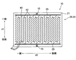
- FIG. 4 is a plan view showing the transparent heating element in the direction normal to the sheet surface thereof, and is a plan view showing an example of the heating conductor.
- FIG. 5 is a plan view showing the transparent heating element in a direction normal to the sheet surface thereof, and is a plan view showing a first modified example of the heating conductor.
- FIG. 6 is a plan view showing the transparent heating element in the direction normal to the sheet surface thereof, and is a plan view showing a second modified example of the heating conductor.
- FIG. 7 is a plan view showing the transparent heat generating element in a direction normal to the sheet surface thereof, and is a plan view showing an example of a third modification of the heat generating conductor.
- FIG. 8 is a plan view showing the transparent heat generating element in a direction normal to the sheet surface thereof, and is a plan view showing another example of the third modification of the heat generating conductor.
- FIG. 9 is an enlarged view showing a part of a connecting conductor in another example of the third modification of the heat generating conductor of FIG. 8.
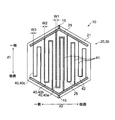
- FIG. 10 is a plan view showing the transparent heating element from the direction normal to the sheet surface thereof, and is a plan view showing a fourth modified example of the heating conductor.
- FIG. 10A is a plan view showing a further modification of the transparent heating element shown in FIG.
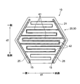
- FIG. 11 is a plan view showing the transparent heating element in the direction normal to the sheet surface thereof, and is a plan view showing another modified example of the heating conductor.
- FIG. 12 is a plan view showing the transparent heating element in the direction normal to the sheet surface thereof, which is a plan view showing a modified example of the bus bar.
- FIG. 12A is a plan view showing the transparent heating element in the direction normal to the sheet surface thereof, and is a plan view showing another modified example of the bus bar.
- a sheet with a conductor is a concept that also includes members that can be called a plate or a film, and therefore, "a sheet with a conductor” means “a plate with a conductor” or "a film with a conductor”. It cannot be distinguished from the called member only by the difference in designation.
- sheet surface means the target sheet-shaped member (plate shape when the target sheet-shaped (plate-shaped, film-shaped) member is viewed as a whole and comprehensively.
- a member, a film-like member refers to a surface that coincides with the plane direction.
- FIG. 1 is a diagram schematically showing an automobile equipped with a transparent heating element
- FIG. 2 is a diagram of the transparent heating element viewed from a direction normal to the plate surface thereof
- FIG. 3 is a sectional view of the transparent heating element taken along line III-III of FIG.
- an automobile as an example of the moving body 1 includes a sensor device 2.
- the sensor device 2 includes a sensor 8 and a heating element with a cover 3 that is arranged so as to face the sensor 8.
- the heating element 3 with a cover has a cover 4 and a transparent heating element 10 provided on the cover 4.
- Such a cover 4 protects the sensor 8 from the outside.
- the cover 4 may be provided with a design property.
- the cover 4 may be an emblem 5 that imparts a design property to the moving body 1. That is, in the illustrated example, an automobile as an example of the moving body 1 includes the sensor 8, the emblem 5 and the transparent heating element 10 that are arranged to face the sensor 8.
- a radar of a collision prevention system can be exemplified.
- the transparent heating element 10 is provided on the emblem 5.
- the transparent heating element 10 is a small member having a size similar to that of the emblem 5 of an automobile, and is, for example, a plate-shaped member having a rectangular shape whose one side is 50 mm or more and 250 mm or less in a plan view.
- the automobile also has a power source 7 such as a battery.
- the emblem 5 includes a first area 5a and a second area 5b.
- the first area 5a is an area for displaying a logo mark or the like by characters or symbols in the emblem 5 and has a glossy color such as silver.
- the second area 5b is a background area of a logo mark or the like in the emblem 5 and has a dark color such as black. Therefore, the reflectance of the first region 5a is higher than the reflectance of the second region 5b.
- the logo mark or the like is displayed by the second area 5b having a dark color
- the first area 5a having the glossy color is the background of the logo mark or the like. Good.
- FIG. 2 shows the transparent heating element 10 provided on the emblem 5 as viewed from the normal direction of the plate surface.
- FIG. 2 shows an emblem 5 including a shape of “A” as an example.
- the area for forming the character "A” is the first area 5a having a glossy color
- the area other than the area for forming the character "A” is a dark-colored color. Is the second region 5b.
- FIG. 3 shows a sectional view of the transparent heating element 10 of FIG. 2 taken along the line III-III.
- the transparent heating element 10 provided on the emblem 5 is a transparent layer 11 made of a resin, a bonding agent, or the like, and is laminated on the transparent layer 11 or embedded in the transparent layer 11.
- FIG. 3A shows a sectional view of the heating element 3 with a cover shown in FIG.
- the emblem 5 is joined to the transparent heating element 10 via the transparent layer 11.
- the transparent layer 11 on the side of the conductor-equipped sheet 20 on which the heating conductor 30 described later is provided and the base material 21 described later are provided.
- the transparent layer 11 on the closed side may be made of the same material and the same, or at least one of the material and the configuration may be different from each other.
- the conductor-equipped sheet 20 includes a base material 21, a heat-generating conductor 30 provided on the surface of the base material 21, and a pair of bus bars 25 for energizing the heat-generating conductor 30.
- the bus bar 25 is preferably arranged only at a position overlapping the second region 5b of the emblem 5.
- the heat-generating conductors 30 are preferably arranged at a higher density in a position overlapping the second region 5b than in a position overlapping the first region 5a of the emblem 5, and are arranged only at a position overlapping the second region 5b. Is more preferable.
- the side of the heat generating conductor 30 opposite to the side of the base material 21 faces the emblem 5. In other words, the side of the heating conductor 30 opposite to the side facing the emblem 5, that is, the side of the base material 21, can be observed from the outside.
- the transparent heating element 10 has a wiring portion 15 for energizing the heating conductor 30.
- the heat generating conductor 30 is energized from the wiring portion 15 via the bus bar 25 of the conductor-equipped sheet 20 by the power source 7 such as a battery, and the heat generating conductor 30 is heated by resistance heating.
- the heat generated by the heat-generating conductor 30 is transmitted to the surface of the transparent heating element 10 and warms the surface of the transparent heating element 10. This makes it possible to remove snow and water droplets attached to the surface of the transparent heating element 10. Therefore, the transparent heating element 10 can remove snow and water droplets that interfere with radio waves from the position facing the sensor 8 and allow the sensor 8 to function normally.
- the “transparent” of the transparent heating element 10 means that the transparent heating element 10 has such transparency that one side of the transparent heating element can be seen through the other side. , For example, having a visible light transmittance of 30% or more, more preferably 70% or more.
- the visible light transmittance is measured at a wavelength of 380 nm to 780 nm using a spectrophotometer (“UV-3100PC” manufactured by Shimadzu Corporation, JIS K 0115 compliant product). Is specified as the average value of.
- the conductor-equipped sheet 20 has substantially the same plane dimension as the transparent heating element 10 and is arranged over the entire transparent heating element 10.
- each component of the conductor-equipped sheet 20 will be described.
- the base material 21 is a member that supports the heating conductor 30.
- the base material 21 is a transparent electrically insulating film.
- any material may be used as long as it is capable of transmitting visible light and appropriately supporting the heat generating conductor 30, and for example, polyethylene terephthalate, polyethylene naphthalate, polycarbonate, polystyrene, cyclic polyolefin, etc. Can be mentioned.
- the base material 21 has a thickness of 0.03 mm or more and 0.20 mm or less in consideration of light transmittance, appropriate supportability of the heat-generating conductor 30, durability, thermal conductivity, and the like. Is preferred.
- the pair of bus bars 25 are arranged apart from each other in the first direction d1, and are electrically connected to the corresponding wiring portions 15.
- the voltage of the power supply 7 connected to the wiring portion 15 is applied between the pair of bus bars 25.
- the bus bar 25 is arranged in the vicinity of the outer edge portion of the conductor-equipped sheet 20.
- FIG. 4 is a plan view of the conductor-equipped sheet 20 viewed from the direction normal to the sheet surface.
- the heat generating conductor 30 is arranged so as to connect the pair of bus bars 25, and electrically connects the pair of bus bars 25. When a voltage is applied via the wiring portion 15 and the bus bar 25, the heating conductor 30 generates heat by resistance heating. Then, this heat is transferred to the surface of the transparent heating element 10 to heat the surface of the transparent heating element 10.
- the heat-generating conductor 30 has a plurality of connecting conductors 40.
- Each of the plurality of connecting conductors 40 connects the pair of bus bars 25.
- the connecting conductors 40 extend in the first direction d1 as a whole and are arranged in the second direction d2 that is non-parallel to the first direction d1.
- each bus bar extends in the second direction d2.
- the first direction d1 and the second direction d2 are orthogonal to each other.
- Examples of the material for forming the connecting conductor 40 of the bus bar 25 and the heat generating conductor 30 include gold, silver, copper, platinum, aluminum, chromium, molybdenum, nickel, titanium, palladium, indium, and tungsten. And one or more of alloys containing one or more of these metals.
- the heating conductor 30 and the bus bar 25 may be formed of the same material, or may be formed of different materials.
- the heat-generating conductor 30 may be formed using an opaque metal material as described above.
- the ratio of the area on the base material 21 that is not covered by the heat-generating conductor 30, that is, the non-coverage ratio is as high as 70% or more and 99% or less.
- the line width W of the connecting conductor 40 is 20 ⁇ m or less. Therefore, the region where the heat-generating conductor 30 is provided is transparent as a whole, and the presence of the heat-generating conductor 30 does not impair the transparency of the transparent heat-generating body 10.
- the heat-generating conductors 30 are arranged at a higher density in a position overlapping the second region 5b than in a position overlapping the first region 5a of the emblem 5.
- the non-coverage rate of the connection conductor 40 in the first region 5a is higher than the non-coverage rate of the connection conductor 40 in the second region 5b.
- the heat-generating conductor 30 is arranged only at a position overlapping the second region 5b. In other words, it is more preferable that the first region 5a is not covered with the connecting conductor 40, that is, the connecting conductor 40 is not arranged in the first region 5a.
- the non-coverage of the connecting conductor 40 in the first region 5a is high, and more preferably, the connecting conductor 40 is not arranged in the first region 5a. It is less likely to be harmed by the body 40.
- the non-coverage of the bus bar 25 in the first region 5a is high, and more preferably, the bus bar 25 is not arranged in the first region 5a. 40 is less likely to be harmed.
- the connecting conductor 40 has a rectangular cross section as a whole.
- the width W of the connecting conductor 40 that is, the width W along the plate surface of the transparent heating element 10 is 2 ⁇ m or more and 20 ⁇ m or less, and the height (thickness) H, that is, a normal line to the plate surface of the transparent heating element 10.
- the height (thickness) H along the direction is preferably 1 ⁇ m or more and 60 ⁇ m or less. According to the connecting conductor 40 having such a size, the connecting conductor 40 is sufficiently thinned, so that the heating conductor 30 can be effectively made invisible.
- the connecting conductor 40 includes a first dark layer 47 that covers the surface of the conductive metal layer 46 and the surface of the conductive metal layer 46 that faces the base material 21.
- a second dark color layer 48 that covers the surface of the conductive metal layer 46 opposite to the side facing the base material 21 and both side surfaces may be included.
- the conductive metal layer 46 made of a metal material having excellent conductivity exhibits a relatively high reflectance. Then, when light is reflected by the conductive metal layer 46 that forms the connecting conductor 40 of the heat-generating conductor 30, the reflected light becomes visible, and the emblem 5 in which the transparent heat-generating body 10 is provided is visible. The design may be deteriorated.
- the first and second dark color layers 47 and 48 cover at least a part of the surface of the conductive metal layer 46.
- the first and second dark color layers 47 and 48 may be layers having a lower visible light reflectance than the conductive metal layer 46, for example, a low lightness achromatic color such as black or dark gray, or brown or navy blue, It is a layer exhibiting a dark color such as a low-lightness chromatic color such as dark green, dark purple, and muddy fat.
- a low lightness achromatic color such as black or dark gray, or brown or navy blue
- a dark color such as a low-lightness chromatic color such as dark green, dark purple, and muddy fat.
- the dark color layer use black iron oxide (Fe 3 O 4 ), carbon (carbon), copper oxide (copper (II) oxide CuO), copper nitride, copper oxynitride, copper-cobalt alloy, etc. You can The dark color layers 47 and 48 make it difficult for the conductive metal layer 46 to
- the side of the heating conductor 30 opposite to the side of the base material 21 faces the emblem 5.
- the connecting conductor 40 is provided at least on the side opposite to the side facing the emblem 5 (cover 4). It is preferable to include the dark color layer 47. Further, it is preferable that the bus bar 25 also includes a dark layer.
- the bus bar 25 is provided with a dark color layer at least on the side opposite to the side facing the emblem 5 (cover 4). It is preferable to include.
- the transparent heating element 10 of the present embodiment is about the same size as the emblem 5 so as to be provided on the emblem 5 of the automobile. That is, the transparent heating element 10 is a small member as compared with the conventional transparent heating element used as a windshield of an automobile. If the transparent heating element 10 is small, it may be difficult to make the heating conductor 30 have an appropriate resistance value, and the resistance heating of the transparent heating element 10 may be insufficient. In order to increase the resistance heating, it is required to increase the resistance value of the heating conductor 30. Therefore, in order to increase the resistance value of the heating conductor 30, it has been considered to reduce the cross-sectional area of the connecting conductor 40, that is, to reduce the width W of the connecting conductor 40.
- the width W of the connecting conductor 40 is made too narrow, the strength of the connecting conductor 40 will be insufficient, and if a shock is applied to the transparent heating element 10, the connecting conductor 40 may be broken. Therefore, it was difficult to achieve the resistance value required for the heat-generating conductor 30 only by adjusting the width W of the connecting conductor 40.
- the connecting conductor 40 is folded back at least twice in the first direction d1. That is, the connecting conductor 40 extends from one side of the first direction d1 to the other side while extending from the one side bus bar 25 of the first direction d1 to the other side bus bar 25, and then to the other side of the first direction d1. It is configured to include at least a portion that extends from one side to one side and again extends from one side of the first direction d1 to the other side.
- the path length of the connecting conductor 40 can be lengthened and the resistance value of the heat-generating conductor 30 can be increased by adjusting the position and the number of times it is folded back.
- the path length of the connecting conductor 40 means a length (total length) from the one bus bar 25 to the other bus bar 25 along the connecting conductor 40.
- One connecting conductor 40 includes at least three linear portions 41 and a connecting portion 42 that connects the two linear portions 41 so that the connecting conductor 40 is folded back at least twice in the first direction d1. And, are included.
- the linear portion 41 extends in the first direction d1 in which the pair of bus bars are arranged apart from each other. That is, the linear portion 41 has at least a length along the first direction d1.
- the plurality of linear portions 41 are arranged in the second direction d2.
- one of the linear portions 41 to which a certain connecting portion 42 connects is directly on one side of the first direction d1 from the portion connecting to the connecting portion 42, or another connecting portion. It is indirectly connected to one of the bus bars 25 via 42 and the linear portion 41.
- the other of the linear portions 41 connected to the connection portion 42 is directly on one side of the first direction d1 from the portion connected to the connection portion 42, or via another connection portion 42 and the linear portion 41. It is indirectly connected to the other of the bus bars 25.
- the two linear portions 41 connected to the connecting portion 42a extend to one side in the first direction d1 and are connected to different bus bars 25a and 25b, respectively.
- the connecting conductor 40 that connects the pair of bus bars 25 is folded back to one side in the first direction d1 at the connecting portion 42a.
- one of the linear parts 41 connected to another connection part 42 different from the connection part 42 is directly on the other side of the first direction d1 from the part connected to the connection part 42, or another. It is indirectly connected to the other of the bus bars 25 via the connecting portion 42 and the linear portion 41.
- the other of the linear portions 41 connected to the connecting portion 42 is directly on the other side of the first direction d1 from the portion connected to the connecting portion 42, or via another connecting portion 42 and the linear portion 41. It is indirectly connected to the other of the bus bars 25.
- the two linear portions 41 connected to the connecting portion 42b extend to the other side in the first direction d1 and are connected to different bus bars 25a and 25b, respectively.
- the connection conductor 40 that connects the pair of bus bars 25 is folded back to the other side in the first direction d1 at a connection portion 42.
- the connecting conductor 40 is folded back at least twice in the first direction d1 at the connecting portions 42a and 42b.
- the connecting portion 42 of the connecting conductor 40 connects the linear portions 41 adjacent to each other in the second direction d2.
- the linear portion 41 and the connecting portion 42 are connected to each other at their ends.
- the linear portion 41a of the linear portion 41 arranged on the most one side in the second direction d2 is connected to the bus bar 25a arranged on one side of the first direction d1.
- the linear portion 41b arranged on the most other side in the second direction d2 is connected to the bus bar 25b arranged on the other side in the first direction d1.
- FIG. 5 shows a first modification of the connecting conductor 40.
- the plurality of connecting conductors 40 include a first group of connecting conductors 40A and a second group of connecting conductors 40B. Particularly, in the illustrated example, the plurality of connecting conductors 40 are classified into one of the first group of connecting conductors 40A and the second group of connecting conductors 40B. In the first group of connecting conductors 40A, similarly to the connecting conductor 40 shown in FIG.
- the linear portion 41a arranged on the most one side in the second direction d2 of the connecting conductors 40 is The linear portion 41b, which is connected to the bus bar 25a arranged on one side of the first direction d1 and arranged on the most other side in the second direction d2, is connected to the bus bar 25b arranged on the other side of the first direction d1. Connected.
- the heat-generating conductor 30 further includes a connecting conductor 35 that connects two adjacent connecting conductors 40.
- Two adjacent connection conductors 40 are electrically connected by the connection conductor 35. Therefore, even if a disconnection occurs at a portion from one end of the connecting conductor 40 to the connection portion to the connecting conductor 35 due to an external impact or the like, the other end of the connecting conductor 40 can be connected to the connecting conductor 35.
- the portion up to the connection point is connected to another connecting conductor 40 via the connecting conductor 35. As a result, it is possible to maintain heat generation in the portion from the other end of the connection conductor 40 to the connection portion to the connection conductor 35.
- the connecting conductor 35 connects the first group of connecting conductors 40A and the second group of connecting conductors 40B.
- the ratio of the resistance values from the part connected to the connection conductor 35 to the part connected to the bus bar 25b on the other side of the first direction d1 is as follows:
- the resistance value from the portion connected to the bus bar 25a on one side of the first direction d1 to the portion connected to the connection conductor 35 is different from the portion connected to the connection conductor 35 in the first direction d1. It is preferable that the ratio of resistance values up to the portion connected to the bus bar 25b on the side is equal.
- the connecting conductor 35 Since the connecting conductor 35 is provided so as to satisfy this relationship regarding the resistance value ratio, almost no current flows through the connecting conductor 35 when no disconnection occurs. Therefore, by providing the connecting conductor 35, the current flowing through the first group of connecting conductors 40A and the second group of connecting conductors 40B does not change, and the first group of connecting conductors 40A and the second group of connecting conductors 40A With the conductor 40B, it is possible to generate heat as intended.
- connection conductors 40 connected by the connection conductor 35 are line-symmetric with respect to a straight line passing through the connection conductor 35. Can be satisfied.
- the two connection conductors 40 connected by the connection conductor 35 pass through the center of the connection conductor 35 in the second direction d2 and are parallel to the first direction d1. It is line-symmetrical with respect to a straight line L extending in any direction.
- the above-mentioned equal ratio of the two resistance values does not mean that the ratio of the two resistance values is exactly the same, but it does not mean that the ratio of the two resistance values is the same. Including that the ratio of the two resistance values is different to the extent that current can flow through the connection conductor 35 within a range in which the intended heat generation can be sufficiently performed with each of the connection conductors 40B. .. In the present embodiment, specifically, if one of the ratios of the two resistance values described above is within 10% of the other, it may be considered that the ratio of the two resistance values is equal.
- FIG. 6 shows a second modification of the connecting conductor 40.
- a region in which one connecting conductor 40 is arranged in the second direction d2 and another one of the connecting conductors 40 are arranged in the second direction d2.
- the existing areas are different areas and do not overlap.
- a region in which one connecting conductor 40 is arranged in the second direction d2 partially overlaps with a region in which another one connecting conductor 40 is arranged in the second direction d2. Overlap in.
- a region R1 in which the connecting conductor 40a is arranged in the second direction d2 and a connecting conductor 40b adjacent to the connecting conductor 40a are in the second direction d2.
- the region R2 arranged in (1) overlaps with the region R3.
- the connecting conductor 40 is folded back at an arbitrary position between the pair of bus bars 25, for example, near the center in order to adjust the path length.
- the path length of the connecting conductor 40 can be easily adjusted to a length other than the length between the pair of bus bars 25, which is approximately an odd multiple.
- the connecting conductor 40 is connected in the heating conductor 30. This results in a large area where the conductor 40 is not arranged. Since the area where the connecting conductor 40 is not arranged does not generate heat, uneven heat generation occurs between the area where the connecting conductor 40 is arranged and the area where the connecting conductor 40 is not arranged.
- the connecting conductor 40 even if the position at which the connecting conductor 40 is folded back is an arbitrary position between the pair of bus bars 25, for example, near the center, it is at the position where the folding is performed.
- the other connecting conductor 40 is arranged at a position facing each other. Therefore, in order to adjust the path length of the connecting conductor 40, even if the connecting conductor 40 is folded at an arbitrary position between the pair of bus bars 25, a region where the connecting conductor 40 is not arranged is formed. Can be made smaller. Therefore, it is possible to suppress the occurrence of heat generation unevenness in the entire transparent heating element 10 and uniformly heat the entire transparent heating element 10. Moreover, since the distribution of the heat-generating conductors 30 is made uniform, it is possible to make the heat-generating conductors 30 less visible.
- the connecting conductor 40 has the shape of a wavy line that is a combination of curves.
- the connecting conductor 40 may have a linear shape as in other examples, may have a polygonal shape by combining straight lines, or may have a curved shape. May have. Alternatively, it may have a shape that is a combination of these shapes.
- the connecting conductor 40 may have a shape in which arcs are combined.
- the connecting conductor 40 has a shape in which arcs of 180° of the same size are combined with adjacent arcs so as to be opposite to each other.
- the connecting conductor 40 has the shape of a straight line, a curved line, or a combination of straight lines and curves, the path length of the connecting conductor 40 can be appropriately adjusted without changing the general shape of the connecting conductor 40. .. Therefore, the resistance value of the heat-generating conductor 30 having the connecting conductor 40 can be adjusted. Further, even when the transparent heating element 10 is deformed in the extending direction of the connecting conductor 40 when it is press-molded in the step of providing the transparent heating element 10 on the emblem 5 which will be described later, the connecting conductor 40 is unlikely to be cut. Become.
- the general shape of the connecting conductor 40 is an approximate shape of the connecting conductor 40 defined by the length and the direction in which the linear portions 41 and the connecting portions 42 included in the connecting conductor 40 extend. Means
- FIG. 9 shows a part of the connecting conductor 40 shown in FIG. 8 in an enlarged manner.
- the radius r of one arc forming the shape of the connecting conductor 40 shown in FIG. 9 and the width W of the connecting conductor 40 satisfy the following relationship. 0.6 ⁇ (r ⁇ W) 2 /r 2 ⁇ 0.95 That is, the non-coverage rate of one connecting conductor 40 is 60% or more and 95% or less.
- the non-coverage rate of the connecting conductor 40 is 74%.
- the radius r of the arc means the length from the center of the arc formed by the connecting conductor 40 to the outer edge of the connecting conductor 40.
- FIG. 10 shows a fourth modification of the connecting conductor 40.
- the transparent heating element 10 has a hexagonal shape as a whole.
- the pair of bus bars 25 has a polygonal line shape in accordance with the shape of the transparent heating element 10. That is, the bus bar 25 extends in a direction non-parallel to the second direction d2 that is the arrangement direction of the connecting conductors 40. Therefore, the distance between the pair of bus bars 25 in the first direction d1 is not constant at each position in the second direction d2. Therefore, the plurality of connecting conductors 40 that connect the pair of bus bars 25 have different path lengths.
- the width W of one of the connecting conductors 40 is wider than the width W of the other connecting conductor 40 of which the path length is shorter than that of the connecting conductor 40.
- the path length of the connecting conductor 40a is longer than the path length of the connecting conductor 40b, and the path length of the connecting conductor 40b is longer than the path length of the connecting conductor 40c.
- the width W1 of the connecting conductor 40a is wider than the width W2 of the connecting conductor 40b, and the width W2 of the connecting conductor 40b is larger than the width W3 of the connecting conductor 40c.
- the resistance value of the connecting conductor 40 is proportional to the path length of the connecting conductor 40 and inversely proportional to the width W of the connecting conductor 40. Therefore, if the width W of one connection conductor 40 is wider than the width W of another connection conductor 40 having a shorter path length than the connection conductor 40, the resistance value of each connection conductor 40. Can be made uniform. Particularly, if the value obtained by dividing the width W of the connecting conductor 40 by the square of the path length is constant, the heat generated per unit area in each connecting conductor 40 can be made uniform, and transparent heat generation can be achieved. The entire body 10 can be uniformly heated.
- the connecting conductors 40 included in the transparent heating element 10 according to the present embodiment are not limited to the examples shown in FIGS. 4 to 10, and may have a structure such as the connecting conductors 40a to 40e shown in FIG. Good.
- the connecting conductor 40 is folded back twice, but as shown in the connecting conductor 40a shown in FIG. It may be folded back.
- the path length of the connecting conductor 40 can be adjusted and the resistance value of the connecting conductor 40 can be adjusted appropriately.
- the end of the linear portion 41 and the end of the connecting portion 42 are connected, but as shown in the connecting conductor 40b shown in FIG.
- an arbitrary position of the linear portion 41 and an arbitrary position of the connecting portion 42 may be connected. That is, the linear portion 41 and the connecting portion 42 may extend from the portions to which they are connected.
- the linear portion 41 and the connecting portion 42 may intersect with each other.
- the portion extending from the portion where the linear portion 41 and the connecting portion 42 are connected is a dummy portion 43 that does not contribute to the heat generation of the transparent heating element 10 because it is not electrically connected to the pair of bus bars 25.
- the distribution of the heat generating conductor 30 can be made uniform.
- the heat-generating conductors 30 are less likely to be visually recognized, and the design of the transparent heat-generating body 10 can be improved.
- the two linear portions 41 in one connecting conductor 40 are connected by only one connecting portion 42.
- the two linear portions 41 may be connected by the plurality of connecting portions 42. In this case, even if one of the connecting portions 42 is broken, the electrical connection of the connecting conductor 40 can be maintained.
- the above-mentioned dummy part 43 is not only a part extending from the part where the linear part 41 and the connecting part 42 are connected, but also the connecting conductor 40c shown in FIG. It may be the whole of the certain linear portion 41 and the connecting portion 42.
- the linear portion 41 arranged on the most one side in the second direction d2 among the linear portions 41 is connected to one of the bus bars 25. Connected. However, like the connecting conductor 40c shown in FIG. 11, the linear portions 41 other than the linear portion 41 arranged on the most one side in the second direction d2 are connected to the one bus bar 25. Good.
- the connecting portion 42 connects the two linear portions 41 adjacent to each other in the second direction d2, but the connecting conductor 40d shown in FIG. As described above, the two linear portions 41 connected by the connecting portion 42 may not be adjacent to each other in the second direction d2.
- the “linear portion 41 extending in the first direction d1” extends parallel to the first direction d1, but a certain region along the first direction d1. Need only exist, and therefore may extend parallel to the direction inclined with respect to the first direction d1.
- the linear part 41 may include at least a component extending in the first direction d1. That is, it may be inclined with respect to the first direction d1 like the linear portion 41 included in the connecting conductor 40e shown in FIG.
- the connecting portion 42 extends linearly, but like the connecting portion 42 of the connecting conductor 40e shown in FIG. It may be a point where the linear portion 41 contacts.
- one first group of connecting conductors 40A and one second group of connecting conductors 40B are arranged alternately.
- the plurality of first group connecting conductors 40A and the plurality of second group connecting conductors 40B may be alternately arranged.
- two connecting conductors 40A belonging to the first group and two connecting conductors 40B belonging to the second group may be arranged alternately in the second direction d2.
- the connecting conductor 35 may connect the first group of connecting conductors 40A and the second group of connecting conductors 40B that are adjacent to each other in the second direction d2.
- two adjacent connecting conductors 40 are connected by one connecting conductor 35, but two adjacent connecting conductors 40 are connected by a plurality of connecting conductors 35. It may be connected.
- connecting conductor 40 can naturally have a configuration in which the configurations shown in the above examples are combined with each other.
- a dark color film is formed on the base material 21 so as to form the first dark color layer 47.
- the metal film can be formed by a known method. For example, a method of sticking a metal foil such as a copper foil, a plating method including electric field plating and electroless plating, a sputtering method, a CVD method, a PVD method, an ion plating method, or a method combining two or more of these is adopted. can do.
- the resist pattern has a shape corresponding to the heat generating conductor 30 to be formed.
- This resist pattern can be formed by patterning using a known photolithography technique.
- the metal film and the dark film are etched using the resist pattern as a mask. By this etching, the metal film and the dark color film are patterned into a pattern substantially the same as the resist pattern. As a result, the conductive metal layer 46 that forms a part of the connecting conductor 40 is formed from the patterned metal film. In addition, a first dark color layer 47 that forms a part of the connection conductor 40 is formed from the patterned dark color film.
- the etching method is not particularly limited, and a known method can be adopted.
- Known methods include, for example, wet etching using an etching solution and plasma etching. Then, the resist pattern is removed.
- the second dark color layer 48 is formed on the surface and the side surface of the conductive metal layer 46 opposite to the surface on which the first dark color layer 47 is provided.
- the second dark-colored layer 48 is obtained by, for example, performing a darkening treatment (blackening treatment) on a part of the material forming the conductive metal layer 46 so that a metal oxide or a metal sulfide is formed from the part forming the conductive metal layer 46. It is possible to form the second dark color layer 48 made of a material. Further, the second dark color layer 48 may be provided on the surface of the conductive metal layer 46. Further, the surface of the conductive metal layer 46 may be roughened to provide the second dark color layer 48.
- the heat-generating conductor 30 is formed on the base material 21, and the conductor-equipped sheet 20 is manufactured.
- the transparent heating element 10 is formed so that the conductor-equipped sheet 20 is embedded inside. As a result, the transparent heating element 10 shown in FIG. 3 is manufactured.
- the transparent heating element 10 is provided on the emblem 5 by press-molding the emblem 5, for example.
- the transparent heating element 10 is arranged so as to face the sensor 8 and to generate heat by connecting the pair of bus bars 25 and the pair of bus bars 25 that are spaced apart in the first direction d1.
- a plurality of connecting conductors 40 each connecting the pair of bus bars 25, the connecting conductors 40 being non-parallel to the first direction d1. They are arranged in two directions d2 and are folded back at least twice in the first direction d1. According to such a transparent heating element 10, the path length of the connecting conductor 40 can be adjusted by adjusting the position and the number of times the connecting conductor 40 is folded back.
- the resistance value of the heating conductor 30 can be appropriately adjusted to a desired value in the transparent heating element 10 arranged facing the sensor 8.
- the transparent heating element 10 can be appropriately heated.
- the pair of bus bars 25 were formed in the elongated plate shape.
- at least one of the bus bars 25 may be formed by arranging the linear conductors 26 in a mesh pattern having a plurality of openings 27. With such a configuration of the bus bar 25, the transparency of the bus bar 25 can be improved.
- At least one of the length D1 in the second direction d2 and the length D3 in the first direction d1 of the opening 27 of the bus bar 25 has two linear portions 41 adjacent to each other in the second direction d2 of the connecting conductor 40. Is preferably the same as the distance D2. In this case, it becomes difficult to visually distinguish between the bus bar 25 and the connecting conductor 40. Therefore, the presence of the bus bar 25 is less noticeable.
- the width of the linear conductor 26 may be the same as the width of the connecting conductor 40 of the heating conductor 30, or may be different.
- the width of the linear conductor 26 is preferably, for example, 3 ⁇ m or more and 50 ⁇ m or less. According to the linear conductor 26 having such a size, the linear conductor 26 is sufficiently thinned, so that the bus bar 25 can be effectively made invisible.
- the width of the linear conductor 26 is preferably larger than the width of the connecting conductor 40 of the heating conductor 30.
- the width of the linear conductor 26 is preferably twice or more the width of the connecting conductor 40 of the heating conductor 30, and more preferably 3 times or more.
- the width of such a linear conductor 26 is, for example, 10 ⁇ m or more and 80 ⁇ m or less.
- the cross-sectional area of the linear conductor 26 is preferably larger than that of the heat-generating conductor 30. Specifically, the cross-sectional area of the linear conductor 26 is preferably twice or more the cross-sectional area of the connecting conductor 40 of the heat-generating conductor 30, and more preferably three times or more. preferable. Sectional area of such a linear conductor 26 is for example 10 [mu] m 2 or more 4800Myuemu 2 or less.
- the bus bar 25 may be arranged in a narrow area, especially when the transparent heating element 10 is a small member.
- the bus bar 25 is formed by arranging the linear conductors 26 in a mesh pattern, the density of the linear conductors 26 becomes high, and the bus bar 25 may generate more heat than the heat generating conductor 30. is there. Since the region in which the heat-generating conductor 30 is arranged is the region in the transparent heat-generating body 10 that is to generate heat, it is not preferable that the bus bar 25 generate more heat than the heat-generating conductor 30. Therefore, as described above, when the width of the linear conductor 26 is larger than the width of the connecting conductor 40, the resistance of the bus bar 25 can be made lower than the resistance of the heating conductor 30.
- the resistance of the bus bar 25 should be lower than the resistance of the heat-generating conductor 30. You can By setting the resistance of the bus bar 25 lower than that of the heat-generating conductor 30, the heat-generating conductor 30 can generate heat from the bus bar 25. As a result, it is possible to efficiently generate heat in the region of the transparent heating element 10 that should generate heat.
- the bus bar 25 extends in the first direction d1 and is arranged in the second direction d2, and the linear conductors 26 extend in the second direction d2 and in the first direction d1. And the linear conductors 26 that are arranged. Further, the length D1 of the opening 27 of the bus bar 25 in the second direction d2 and the distance D2 of the two linear portions 41 adjacent to each other in the second direction d2 of the connecting conductor 40 are the same in the second direction d2. Is becoming In this case, it is more difficult to visually distinguish the bus bar 25 and the connecting conductor 40, and the bus bar 25 can be made less visible.
- the length D1 in the second direction d2 and the length D3 in the first direction d1 of the opening 27 of the bus bar 25 and the two linear portions 41 adjacent to each other in the second direction d2 of the connecting conductor 40 does not mean that they are exactly the same length, but these lengths are so small that the bus bar 25 becomes inconspicuous due to the presence of the connecting conductor 40. Including that it is different. In the present modification, specifically, if one of these lengths is within 10% of the other, the bus bar 25 becomes sufficiently inconspicuous, and thus may be considered the same.
- the linear conductor 26 may have a shape of a straight line, a curved line, or a combination of straight lines and curved lines, similarly to the connecting conductor 40 shown in FIG. 7.
- the linear conductor 26 may have a shape in which arcs are combined. When the linear conductor 26 has such a shape, the linear conductor 26 is cut even if the transparent heating element 10 is deformed when press-molded in the step of providing the transparent heating element 10 on the emblem 5. It gets harder.
- the bus bar 25 is arranged closer to the periphery of the transparent heating element 10 than the heating conductor 30, the bus bar 25 is easily deformed in the manufacturing process of the transparent heating element 10, and thus the linear conductor 26 is easily cut. For this reason, since the linear conductor 26 has a shape in which a curved line or an arc is combined, the effect that the linear conductor 26 is less likely to be cut can be more remarkably exhibited.
- the radius r of one circular arc and the width of the linear conductor 26 that form the shape of the linear conductor 26 are similar to those of the connecting conductor 40 shown in FIG. It is preferable that W satisfies the following relationship. 0.6 ⁇ (r ⁇ W) 2 /r 2 ⁇ 0.95 That is, the non-coverage rate of one linear conductor 26 is 60% or more and 95% or less. By satisfying such a relationship, it becomes difficult for the linear conductor 26 having a shape in which arcs are combined to be thickly observed, and thus the linear conductor 26 is difficult to be visually recognized.
- the first direction d1 is the vertical direction and the second direction d2 is the horizontal direction, but these are the transparent heating element 10 in which the first direction d1 is the vertical direction and the second direction d2 is the vertical direction. It does not only mean that the direction d2 is arranged in the horizontal direction.
- the transparent heating element 10 may be arranged such that the first direction d1 is the vertical direction and the second direction d2 is the horizontal direction, or the first direction d1 is the horizontal direction and the second direction d2 is the vertical direction.
- the first direction d1 and the second direction d2 may both be inclined with respect to the horizontal direction and the vertical direction.
- the wiring portion 15 connected to the bus bars 25 has a lower side in the vertical direction of the bus bars 25, as shown in FIG. 10A. Preferably extends to. Since the emblem 5 is often arranged below the observer, if the wiring portion 15 extends below the bus bar 25, the wiring portion 15 becomes difficult to be visually recognized, and the emblem 5 in which the transparent heating element 10 is arranged. It becomes difficult to damage the design of the.
- the transparent heating element 10 is provided on the emblem 5 facing the radar of the collision prevention system for the moving body 1.
- the transparent heating element 10 may be arranged so as to face the other sensor 8 of the moving body 1.
- it may be arranged so as to face a camera provided in the moving body 1.
- the transparent heating element 10 may be arranged to face the sensor provided on the outer wall of the building other than the moving body 1, for example.
Landscapes
- Engineering & Computer Science (AREA)
- Radar, Positioning & Navigation (AREA)
- Remote Sensing (AREA)
- Computer Networks & Wireless Communication (AREA)
- Physics & Mathematics (AREA)
- General Physics & Mathematics (AREA)
- Surface Heating Bodies (AREA)
- Resistance Heating (AREA)
Priority Applications (6)
| Application Number | Priority Date | Filing Date | Title |
|---|---|---|---|
| CA3120843A CA3120843A1 (en) | 2018-11-26 | 2019-11-26 | Transparent heating element, heating element with cover, sensor device, and mobile object |
| KR1020217019446A KR102668152B1 (ko) | 2018-11-26 | 2019-11-26 | 투명 발열체, 커버를 갖는 발열체, 센서 장치, 이동체 |
| EP19889480.0A EP3890434B1 (en) | 2018-11-26 | 2019-11-26 | Transparent heating element, heating element with cover, sensor device, and mobile object |
| EP23188112.9A EP4246711A3 (en) | 2018-11-26 | 2019-11-26 | Transparent heating element, heating element with cover, sensor device, and mobile object |
| CN201980075955.4A CN113056960A (zh) | 2018-11-26 | 2019-11-26 | 透明发热体、带盖体的发热体、传感器装置、移动体 |
| US17/297,420 US20220039216A1 (en) | 2018-11-26 | 2019-11-26 | Transparent heating element, heating element with cover, sensor device, and mobile object |
Applications Claiming Priority (2)
| Application Number | Priority Date | Filing Date | Title |
|---|---|---|---|
| JP2018-220599 | 2018-11-26 | ||
| JP2018220599A JP6756356B2 (ja) | 2017-11-27 | 2018-11-26 | 透明発熱体、カバー付き発熱体、センサ装置、移動体 |
Publications (1)
| Publication Number | Publication Date |
|---|---|
| WO2020111060A1 true WO2020111060A1 (ja) | 2020-06-04 |
Family
ID=66971961
Family Applications (1)
| Application Number | Title | Priority Date | Filing Date |
|---|---|---|---|
| PCT/JP2019/046168 Ceased WO2020111060A1 (ja) | 2018-11-26 | 2019-11-26 | 透明発熱体、カバー付き発熱体、センサ装置、移動体 |
Country Status (7)
| Country | Link |
|---|---|
| US (1) | US20220039216A1 (https=) |
| EP (2) | EP4246711A3 (https=) |
| JP (2) | JP6756356B2 (https=) |
| KR (1) | KR102668152B1 (https=) |
| CN (1) | CN113056960A (https=) |
| CA (1) | CA3120843A1 (https=) |
| WO (1) | WO2020111060A1 (https=) |
Cited By (2)
| Publication number | Priority date | Publication date | Assignee | Title |
|---|---|---|---|---|
| WO2025089052A1 (ja) * | 2023-10-26 | 2025-05-01 | 京セラ株式会社 | ヒータ |
| WO2025105139A1 (ja) * | 2023-11-13 | 2025-05-22 | Agc株式会社 | 光センサ用カバー及び光センサ |
Families Citing this family (14)
| Publication number | Priority date | Publication date | Assignee | Title |
|---|---|---|---|---|
| US11264691B2 (en) * | 2019-07-15 | 2022-03-01 | Kymeta Corporation | Ground plane heater |
| JP7407007B2 (ja) * | 2020-02-07 | 2023-12-28 | 株式会社東海理化電機製作所 | 車両用撮像装置 |
| JP7326187B2 (ja) * | 2020-02-28 | 2023-08-15 | クアーズテック株式会社 | 面状ヒータ |
| US12429557B2 (en) | 2020-03-16 | 2025-09-30 | Lintec Corporation | Pseudo sheet structure, sheet conductive member, and sensor device |
| JP7505238B2 (ja) * | 2020-04-07 | 2024-06-25 | 株式会社デンソー | フィルムヒータ |
| JP2021174690A (ja) * | 2020-04-27 | 2021-11-01 | 豊田合成株式会社 | ヒータシート及び車載センサカバー |
| JP7494633B2 (ja) * | 2020-07-30 | 2024-06-04 | 大日本印刷株式会社 | 導電体付きシート、合わせ板、移動体、及び導電体付きシートの製造方法 |
| JPWO2022079999A1 (https=) * | 2020-10-13 | 2022-04-21 | ||
| JP7334713B2 (ja) * | 2020-11-24 | 2023-08-29 | トヨタ自動車株式会社 | 電磁波透過性ヒータ |
| JP7611566B2 (ja) * | 2021-02-02 | 2025-01-10 | 東京コスモス電機株式会社 | 電子部品およびその製造方法 |
| JP7682724B2 (ja) * | 2021-07-14 | 2025-05-26 | 豊田合成株式会社 | 電磁波透過カバー |
| JP7800019B2 (ja) * | 2021-08-19 | 2026-01-16 | 大日本印刷株式会社 | 導電体 |
| JP7797236B2 (ja) * | 2022-02-21 | 2026-01-13 | 豊田合成株式会社 | 車両外装品用ヒータ及び車両外装品用ヒータの製造方法 |
| DE102023108742A1 (de) * | 2023-04-05 | 2024-10-10 | Marquardt Gmbh | Zierteil für ein Interieur eines Fahrzeugs sowie ein zugehöriges Verfahren zu dessen Herstellung |
Citations (12)
| Publication number | Priority date | Publication date | Assignee | Title |
|---|---|---|---|---|
| JPS57140255A (en) * | 1981-02-25 | 1982-08-30 | Nissan Motor Co Ltd | Hot wire type anti-mist window glass for vehicle |
| JPH041723A (ja) * | 1990-04-19 | 1992-01-07 | Asahi Optical Co Ltd | 熱書き込み型液晶表示装置 |
| JPH0961781A (ja) * | 1995-08-29 | 1997-03-07 | Asahi Optical Co Ltd | 液晶投影装置 |
| JPH10509567A (ja) * | 1994-09-28 | 1998-09-14 | グラス、アンテナズ、テクノロジー、リミテッド | アンテナ |
| JPH11142749A (ja) * | 1997-11-12 | 1999-05-28 | Olympus Optical Co Ltd | 顕微鏡 |
| JP2004528699A (ja) * | 2001-06-01 | 2004-09-16 | サン−ゴバン グラス フランス | 加熱される窓 |
| KR20070046236A (ko) * | 2005-10-29 | 2007-05-03 | 임정규 | 기판에 보이지 않는 열선을 형성하는 방법 및 그 기판을이용한 부착식 성에 제거 장치 |
| JP2009523084A (ja) * | 2005-12-29 | 2009-06-18 | エクスアテック、エル.エル.シー. | ロボット分配用途用に最適化された母線設計 |
| JP2010100006A (ja) | 2008-10-27 | 2010-05-06 | Japan Steel Works Ltd:The | 車両用ミリ波レーダ用カバーの成形方法と成形用金型 |
| JP2011514647A (ja) * | 2008-03-17 | 2011-05-06 | エルジー・ケム・リミテッド | 発熱体およびその製造方法 |
| JP2016539667A (ja) * | 2013-09-29 | 2016-12-22 | アボミナブル ラブス、エルエルシー | 多領域加熱される保護眼鏡 |
| JP2017041406A (ja) * | 2015-08-21 | 2017-02-23 | 大日本印刷株式会社 | 透明発熱板及び透明発熱板を備えた乗り物 |
Family Cites Families (24)
| Publication number | Priority date | Publication date | Assignee | Title |
|---|---|---|---|---|
| JPH11135243A (ja) * | 1997-10-28 | 1999-05-21 | Sharp Corp | 面状発熱体 |
| US6452138B1 (en) * | 1998-09-25 | 2002-09-17 | Thermosoft International Corporation | Multi-conductor soft heating element |
| JP2004020514A (ja) * | 2002-06-20 | 2004-01-22 | Hitachi Ltd | 車載用レーダ装置 |
| WO2005089019A2 (de) * | 2004-03-08 | 2005-09-22 | W.E.T. Automotive Systems Ag | Flächiges heizelement |
| DE102004050158B3 (de) * | 2004-10-15 | 2006-04-06 | Saint-Gobain Sekurit Deutschland Gmbh & Co. Kg | Transparente Scheibe mit einer beheizbaren Beschichtung |
| KR200425284Y1 (ko) * | 2006-05-18 | 2006-09-05 | 김민정 | 카본섬유 면상발열체 |
| JP2009259714A (ja) * | 2008-04-18 | 2009-11-05 | Sharp Corp | 面状発熱体およびそれを備えた定着装置ならびに画像形成装置 |
| JP2010205432A (ja) * | 2009-02-27 | 2010-09-16 | Fujifilm Corp | 透明導電体及び透明発熱体 |
| JP2010251230A (ja) * | 2009-04-20 | 2010-11-04 | Fujifilm Corp | 電熱窓ガラス |
| KR101411374B1 (ko) * | 2013-04-29 | 2014-07-04 | 권화중 | 양면 히팅 방탄유리 |
| KR101638244B1 (ko) * | 2014-10-06 | 2016-07-08 | 서울과학기술대학교 산학협력단 | 면상 발열체 및 그 제조 방법 |
| JP6643334B2 (ja) * | 2014-11-03 | 2020-02-12 | イリノイ トゥール ワークス インコーポレイティド | 車両用センサーシステムの透過性フロント面ヒーター |
| JP6481386B2 (ja) * | 2015-01-29 | 2019-03-13 | 大日本印刷株式会社 | 発熱板及び乗り物 |
| JP6387864B2 (ja) * | 2015-03-06 | 2018-09-12 | 東芝ライテック株式会社 | ヒータおよび画像形成装置 |
| JP6571550B2 (ja) * | 2015-03-09 | 2019-09-04 | 株式会社ニューフレアテクノロジー | ヒータおよびこれを用いた半導体製造装置 |
| CN104869676A (zh) * | 2015-04-24 | 2015-08-26 | 冯冠平 | 一种低电压透明电热膜及其制备工艺 |
| JP2016223161A (ja) * | 2015-05-29 | 2016-12-28 | 大日本印刷株式会社 | 透明発熱板及び透明発熱板を備えた窓 |
| JP2016223948A (ja) | 2015-06-01 | 2016-12-28 | サカエ理研工業株式会社 | 車両用レドーム及び車両用レーダー装置 |
| JP2017019313A (ja) * | 2015-07-07 | 2017-01-26 | 株式会社豊田自動織機 | 装飾部品 |
| EP3955704B1 (en) * | 2015-11-17 | 2025-07-23 | Dai Nippon Printing Co., Ltd. | Heating electrode device, electrical heating glass, heat-generating plate, vehicle, window for building, sheet with conductor, conductive pattern sheet, conductive heat-generating body, laminated glass, and manufacturing method for conductive heat-generating body |
| WO2017151348A1 (en) * | 2016-02-29 | 2017-09-08 | Illinois Tool Works, Inc. | Hybrid heater for vehicle sensor system |
| WO2017204291A1 (ja) * | 2016-05-26 | 2017-11-30 | 日本板硝子株式会社 | 合わせガラス |
| US10651530B2 (en) * | 2016-06-01 | 2020-05-12 | Toyoda Gosei Co., Ltd. | Decorative component for vehicle |
| US10974661B2 (en) | 2016-10-21 | 2021-04-13 | Toyoda Gosei Co., Ltd. | Decorative part for vehicle and method for manufacturing same |
-
2018
- 2018-11-26 JP JP2018220599A patent/JP6756356B2/ja active Active
-
2019
- 2019-11-26 CA CA3120843A patent/CA3120843A1/en active Pending
- 2019-11-26 US US17/297,420 patent/US20220039216A1/en not_active Abandoned
- 2019-11-26 WO PCT/JP2019/046168 patent/WO2020111060A1/ja not_active Ceased
- 2019-11-26 CN CN201980075955.4A patent/CN113056960A/zh active Pending
- 2019-11-26 EP EP23188112.9A patent/EP4246711A3/en active Pending
- 2019-11-26 EP EP19889480.0A patent/EP3890434B1/en active Active
- 2019-11-26 KR KR1020217019446A patent/KR102668152B1/ko active Active
-
2020
- 2020-08-26 JP JP2020142970A patent/JP7284939B2/ja active Active
Patent Citations (12)
| Publication number | Priority date | Publication date | Assignee | Title |
|---|---|---|---|---|
| JPS57140255A (en) * | 1981-02-25 | 1982-08-30 | Nissan Motor Co Ltd | Hot wire type anti-mist window glass for vehicle |
| JPH041723A (ja) * | 1990-04-19 | 1992-01-07 | Asahi Optical Co Ltd | 熱書き込み型液晶表示装置 |
| JPH10509567A (ja) * | 1994-09-28 | 1998-09-14 | グラス、アンテナズ、テクノロジー、リミテッド | アンテナ |
| JPH0961781A (ja) * | 1995-08-29 | 1997-03-07 | Asahi Optical Co Ltd | 液晶投影装置 |
| JPH11142749A (ja) * | 1997-11-12 | 1999-05-28 | Olympus Optical Co Ltd | 顕微鏡 |
| JP2004528699A (ja) * | 2001-06-01 | 2004-09-16 | サン−ゴバン グラス フランス | 加熱される窓 |
| KR20070046236A (ko) * | 2005-10-29 | 2007-05-03 | 임정규 | 기판에 보이지 않는 열선을 형성하는 방법 및 그 기판을이용한 부착식 성에 제거 장치 |
| JP2009523084A (ja) * | 2005-12-29 | 2009-06-18 | エクスアテック、エル.エル.シー. | ロボット分配用途用に最適化された母線設計 |
| JP2011514647A (ja) * | 2008-03-17 | 2011-05-06 | エルジー・ケム・リミテッド | 発熱体およびその製造方法 |
| JP2010100006A (ja) | 2008-10-27 | 2010-05-06 | Japan Steel Works Ltd:The | 車両用ミリ波レーダ用カバーの成形方法と成形用金型 |
| JP2016539667A (ja) * | 2013-09-29 | 2016-12-22 | アボミナブル ラブス、エルエルシー | 多領域加熱される保護眼鏡 |
| JP2017041406A (ja) * | 2015-08-21 | 2017-02-23 | 大日本印刷株式会社 | 透明発熱板及び透明発熱板を備えた乗り物 |
Cited By (2)
| Publication number | Priority date | Publication date | Assignee | Title |
|---|---|---|---|---|
| WO2025089052A1 (ja) * | 2023-10-26 | 2025-05-01 | 京セラ株式会社 | ヒータ |
| WO2025105139A1 (ja) * | 2023-11-13 | 2025-05-22 | Agc株式会社 | 光センサ用カバー及び光センサ |
Also Published As
| Publication number | Publication date |
|---|---|
| JP2019096617A (ja) | 2019-06-20 |
| CA3120843A1 (en) | 2020-06-04 |
| EP4246711A8 (en) | 2023-12-27 |
| EP3890434A1 (en) | 2021-10-06 |
| EP4246711A3 (en) | 2023-12-20 |
| CN113056960A (zh) | 2021-06-29 |
| JP2020191309A (ja) | 2020-11-26 |
| JP6756356B2 (ja) | 2020-09-16 |
| KR20210092300A (ko) | 2021-07-23 |
| EP4246711A2 (en) | 2023-09-20 |
| US20220039216A1 (en) | 2022-02-03 |
| JP7284939B2 (ja) | 2023-06-01 |
| EP3890434A4 (en) | 2022-11-23 |
| KR102668152B1 (ko) | 2024-05-23 |
| EP3890434B1 (en) | 2024-05-08 |
Similar Documents
| Publication | Publication Date | Title |
|---|---|---|
| JP7284939B2 (ja) | 透明発熱体、カバー付き発熱体、センサ装置、移動体 | |
| JP6840452B2 (ja) | 合わせガラスおよび導電性発熱体 | |
| JP6858480B2 (ja) | 合わせガラスおよび導電性発熱体 | |
| JP6913294B2 (ja) | 発熱板、導電体付きシート、乗り物及び建築物用窓 | |
| JP2021187712A (ja) | 導電基板および合わせ板 | |
| JP2017210146A (ja) | パターン導電体、発熱用導電体、導電体付きシート、発熱板、乗り物および建築物 | |
| JP7316535B2 (ja) | 発熱用導電体、発熱板および発熱用導電体の製造方法 | |
| JP6951674B2 (ja) | 発熱用導電体、導電体付きシート、発熱板および乗り物 | |
| CN113303028B (zh) | 图案导电体、发热板以及移动体 | |
| JP7581672B2 (ja) | 導電体付きシート、合わせ板、及び移動体 | |
| JP6897706B2 (ja) | 発熱板及び乗り物 | |
| JP7405096B2 (ja) | パターン導電体、バスバー付きパターン導電体、合わせ板、仕切部材及び移動体 | |
| US20220167467A1 (en) | Electromagnetic wave transmitting heater | |
| JP7800019B2 (ja) | 導電体 | |
| JP6770703B2 (ja) | パターン導電体、発熱用導電体、導電体付きシート、発熱板、乗り物および建築物 | |
| JP6540037B2 (ja) | 発熱板及び乗り物 | |
| JP2018092881A (ja) | 発熱用導電体、発熱板および乗り物 | |
| JP2022184524A (ja) | 導電体、合わせ板及びセンサシステム | |
| JP7494633B2 (ja) | 導電体付きシート、合わせ板、移動体、及び導電体付きシートの製造方法 | |
| JP6930583B2 (ja) | 合わせガラスおよび導電性発熱体 | |
| JP6740715B2 (ja) | パターン導電体、発熱用導電体、導電体付きシート、発熱板、乗り物および建築物 | |
| JP2022094697A (ja) | パターン導電体、導電体付きシート、透明発熱カバー及び透明発熱カバーの製造方法 | |
| JP2023046851A (ja) | 電磁波透過カバー | |
| JP2023145174A (ja) | 導電体付きシート、合わせ板、センサシステム | |
| JP2017226566A (ja) | 合わせガラス及び乗り物 |
Legal Events
| Date | Code | Title | Description |
|---|---|---|---|
| 121 | Ep: the epo has been informed by wipo that ep was designated in this application |
Ref document number: 19889480 Country of ref document: EP Kind code of ref document: A1 |
|
| ENP | Entry into the national phase |
Ref document number: 3120843 Country of ref document: CA |
|
| NENP | Non-entry into the national phase |
Ref country code: DE |
|
| ENP | Entry into the national phase |
Ref document number: 20217019446 Country of ref document: KR Kind code of ref document: A |
|
| ENP | Entry into the national phase |
Ref document number: 2019889480 Country of ref document: EP Effective date: 20210628 |