WO2020111035A1 - 位置検出装置用磁石ユニット及び位置検出装置 - Google Patents
位置検出装置用磁石ユニット及び位置検出装置 Download PDFInfo
- Publication number
- WO2020111035A1 WO2020111035A1 PCT/JP2019/046081 JP2019046081W WO2020111035A1 WO 2020111035 A1 WO2020111035 A1 WO 2020111035A1 JP 2019046081 W JP2019046081 W JP 2019046081W WO 2020111035 A1 WO2020111035 A1 WO 2020111035A1
- Authority
- WO
- WIPO (PCT)
- Prior art keywords
- magnet
- pole
- magnets
- magnetic
- position detection
- Prior art date
- Legal status (The legal status is an assumption and is not a legal conclusion. Google has not performed a legal analysis and makes no representation as to the accuracy of the status listed.)
- Ceased
Links
Images


Classifications
-
- G—PHYSICS
- G01—MEASURING; TESTING
- G01D—MEASURING NOT SPECIALLY ADAPTED FOR A SPECIFIC VARIABLE; ARRANGEMENTS FOR MEASURING TWO OR MORE VARIABLES NOT COVERED IN A SINGLE OTHER SUBCLASS; TARIFF METERING APPARATUS; MEASURING OR TESTING NOT OTHERWISE PROVIDED FOR
- G01D5/00—Mechanical means for transferring the output of a sensing member; Means for converting the output of a sensing member to another variable where the form or nature of the sensing member does not constrain the means for converting; Transducers not specially adapted for a specific variable
- G01D5/12—Mechanical means for transferring the output of a sensing member; Means for converting the output of a sensing member to another variable where the form or nature of the sensing member does not constrain the means for converting; Transducers not specially adapted for a specific variable using electric or magnetic means
Definitions
- the present invention relates to a position detection technique for detecting the stroke amount of a magnetic sensor from the magnetic field density of a magnet unit.
- a linear encoder is known as a position detection device that detects the stroke amount of a magnetic sensor from the magnetic field density of a magnet unit.
- a conventional technique related to such position detection there is a technique disclosed in Patent Document 1.
- Patent Document 1 discloses a magnetic position detecting device, and the magnetic position detecting device includes a plurality of magnetic members (for example, four magnetic members 1a, 1b, 1c, 1d in FIG. 1 of Patent Document 1). And a magnetic sensing element (for example, four spin valve type magnetoresistive elements SV-GMR1, SV-GMR2, SV-GMR3, SV-GMR4 in FIG. 1 of Patent Document 1). And a sensor) (paragraphs [0023] and [0024] of Patent Document 1).
- the outputs Vout1 and Vout2 as shown in FIG. 1C can be obtained within the stroke range of FIG. 1A of Patent Document 1 by using the connection as shown in FIG. 1B, the magnetic members 1a, 1b, 1c and 1d can be obtained.
- the magnetoresistive elements SV-GMR1, SV-GMR2, SV-GMR3, and SV-GMR4 are relatively movable, the magnetoresistive elements SV-GMR1, SV-GMR2, SV-GMR3 within the stroke range.
- the absolute position of the SV-GMR4 can be uniquely specified or detected (paragraphs [0025] and [0026] of Patent Document 1).
- FIG. 11B of Patent Document 1 for example, instead of the magnetoresistive elements SV-GMR1, SV-GMR2, SV-GMR3, SV-GMR4, Hall elements H1, H2, H3, H4 are used as magnetic sensors. May be used, and the Hall elements H1, H2, H3, and H4 can be connected, for example, as shown in FIG. 12 of Patent Document 1 (paragraphs [0043], [0046], and [0046] of Patent Document 1. 0047]).
- the arrangement of magnets as shown in FIG. 1A of Patent Document 1 corresponds to the arrangement of magnets or the magnetization direction as in Configuration 1-2 of Non-Patent Document 1, while the conventional arrangement of magnets is generally
- Patent Document 2 discloses a position detection device, and the position detection device includes a magnet structure (for example, a magnet configured by the permanent magnet 2 and the auxiliary magnetic bodies 5 and 5 in FIG. 3 of Patent Document 2) and a magnetic field. And a detection unit (for example, the magnetic detection unit 4 in FIG. 1 of Patent Document 2) (paragraph [0016] of Patent Document 2).
- a magnet structure for example, a magnet configured by the permanent magnet 2 and the auxiliary magnetic bodies 5 and 5 in FIG. 3 of Patent Document 2
- a detection unit for example, the magnetic detection unit 4 in FIG. 1 of Patent Document 2 (paragraph [0016] of Patent Document 2).
- Patent Document 2 For example, according to the professor of Patent Document 2, it is possible to expand the magnetic flux density linear region L of FIG. 2 of Patent Document 2 with the auxiliary magnetic bodies 5 and 5, and thus to expand the range of stroke (Patent Document 2). Paragraph 2 [0024]).
- the auxiliary magnetic bodies 5 and 5 do not exist on the plane of the permanent magnet 2 in the real space, in other words, the auxiliary magnetic bodies 5 and 5 and the permanent magnet 2 cannot be arranged on a straight line.
- the size or volume of the magnet structure becomes large. As the size of these devices increases, the position detection device magnet unit becomes expensive.
- One object of the present invention is to provide an inexpensive magnetic position detecting device having an expanded stroke range.
- Other objects of the present invention will become apparent to those skilled in the art by referring to the aspects and best modes illustrated below, and the accompanying drawings.
- a support member that can be arranged to face the magnetic sensor, and a first magnet and a second magnet that are supported by the support member and that are arranged along the first direction,
- the first magnet and the second magnet are bar magnets whose end faces are magnetic pole faces,
- the direction in which the N pole of the first magnet is formed is orthogonal to the direction in which the N pole of the second magnet is formed,
- a magnet unit for a position detecting device wherein an N pole of one of the first magnet and the second magnet is formed along the first direction.
- the first magnet and the second magnet that form the magnet unit for the position detection device are formed by bar magnets whose end faces are magnetic pole faces.
- the direction in which the N pole of the first magnet is formed is orthogonal to the direction in which the N pole of the second magnet is formed, and the N pole of either one of the first magnet and the second magnet is formed.
- the orientation is along the first direction.
- a bar magnet whose end faces are magnetic pole faces is inexpensive. Even if one of the first magnet and the second magnet arranged along the first direction is lengthened according to the stroke amount of the magnetic sensor, a bar magnet whose end face is a magnetic pole face is used. Can be made cheaper. It is possible to provide an inexpensive magnet unit for a position detection device.
- FIG. 3 is a perspective view of a position detecting device according to an embodiment of the present invention.
- FIG. It is the figure which showed typically the position detection apparatus shown in FIG. It is a 3 arrow line view of FIG. It is an output explanatory view of the magnetic sensor shown in FIG.
- the front, rear, up, down, left, and right directions are as follows: Fr is front, Rr is rear, Le is left, Ri is right, Up is up, and Dn is down.
- the x-axis direction is the direction from Le to Ri
- the positive x-axis direction is the Ri direction
- the negative x-axis direction is the Le direction.
- the y-axis direction is the direction from Dn to Up
- the positive y-axis direction is the Up direction
- the negative y-axis direction is the Dn direction.
- the z-axis direction is a direction from Rr to Fr
- the positive z-axis direction is the Fr direction
- the negative z-axis direction is the Rr direction.
- a magnetic position detection device 10 includes a magnet unit 20 composed of a plurality of permanent magnets, and a sensor provided so as to be relatively movable in a magnetic field generated by the magnet unit 20. And a unit 30.
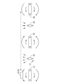
- the magnet unit 20 (the magnet unit 20 for the position detection device) includes a resin support body 21 and first to fifth support bodies 21 supported by the support body 21 and arranged linearly in the left-right direction (first direction). And magnets 22 to 26.
- the magnet unit 20 is manufactured by creating each part of the magnetic member, magnetizing the magnetic member, and then fitting the magnetic member into the support 21. A known method can be adopted for magnetizing the magnetic member.
- the resin forming the support 21 may be polybutylene terephthalate (PBT) or polyphenylene sulfide (PPS).
- the support 21 has, for example, recesses corresponding to the shapes of the first to fifth magnets 22 to 26, and may be bonded to these when the first to fifth magnets 22 to 26 are inserted. .
- the support may be vertically divided into two parts, and the first to fifth magnets may be sandwiched and then sealed (bonded or laser welded) to be integrally formed.
- the first to fifth magnets 22 to 26 can be fixed linearly in the real space along the first direction or the x-axis direction.
- the first to fifth magnets 22 to 26 are each composed of a bar magnet (round bar magnet) having a cylindrical shape with end faces serving as magnetic pole faces.
- the first to fifth magnets 22 to 26 can employ samarium-cobalt (SmCo) or neodymium (Nd-Fe-B: neodymium) as a material.
- the first magnet 22 When the left-right direction is the x-axis, the first magnet 22 has the north pole formed in the positive x-axis direction and the south pole formed in the negative x-axis direction. In other words, one end and the other end of the round bar-shaped first magnet 22 in the longitudinal direction are magnetized so as to indicate the N pole and the S pole, respectively.
- the second magnet 23 adjacent to the first magnet 22 has an N pole formed in the positive direction of the y axis orthogonal to the x axis, while an S pole is formed in the negative direction of the y axis.
- the third magnet 24 adjacent to the second magnet 23 has the N pole formed in the negative direction of the x-axis, while the S pole is formed in the positive direction of the x-axis.
- the fourth magnet 25 adjacent to the third magnet 24 has an N pole formed in the negative y-axis direction, and an S pole formed in the positive y-axis direction.
- the fifth magnet 26 next to the fourth magnet 25 has an N pole formed in the positive x-axis direction, and an S pole formed in the negative x-axis direction.
- the center points of the first to fifth magnets 22 to 26 in the x-axis direction are, for example, 0 [mm], 50 [mm], 100 [mm], 150 [in the x-axis direction or in the stroke range, respectively. mm] and 200 [mm].
- the center points of the magnets 22 to 26 in the x-axis direction are arranged at regular intervals of, for example, 50 [mm].
- the sensor unit 30 is provided so as to face the magnet unit 20, and is movable in parallel and linearly with respect to the magnet unit 20.
- the sensor unit 30 includes a sensor housing 31, a circuit board 32 supported by the sensor housing 31, and a magnetic sensor 33 mounted on the circuit board 32 and capable of detecting the direction of the magnetic field generated by the magnet unit 20. Have.
- the stroke amount (movement amount) of the sensor unit 30 is, for example, 200 [mm].
- the magnetic sensor 33 can be preferably composed of, for example, four Hall elements or magnetoresistive elements so that the magnetic field in the positive and negative directions of the x axis and the positive and negative directions of the y axis can be detected. These Hall elements or magnetoresistive elements are appropriately connected, in other words, appropriately connected so as to obtain outputs corresponding to the magnetic fields in the positive and negative directions of the x axis and the positive and negative directions of the y axis, and the circuit board 32 is An arithmetic unit (differential amplifier, adder, etc.) can be included together with the connection path.
- An arithmetic unit can be included together with the connection path.
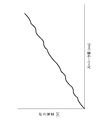
- FIG. 4 is an output explanatory diagram of the magnetic sensor 33 that constitutes the magnetic position detection device of FIG.
- the N poles of the magnets 22 to 26 change every 90 degrees, and the x-axis positive direction, the y-axis positive direction, the x-axis negative direction, and the y-axis Is not a perfect straight line because it is arranged in the negative direction of x and the positive direction of the x-axis, but the output voltage monotonically increases.
- the absolute position of the magnetic sensor 33 within the range of the stroke is Can be uniquely identified or detected.
- the magnets 22-26 are miniaturized by sacrificing the linearity of the output voltage when expanding the range of strokes, which in turn reduces the size of the magnetic position sensing device that includes it. it can.
- the position detection device 10 according to the embodiment can be described as follows.
- the position detection device magnet unit 20 used in the position detection device 10 is A support body 21 that can be arranged to face the magnetic sensor 33, and a first magnet 22 and a second magnet 23 that are supported by the support body 21 and are arranged along the first direction,
- the first magnet 22 and the second magnet 23 are bar magnets whose end faces are magnetic pole faces,
- the direction in which the north pole of the first magnet 22 is formed is orthogonal to the direction in which the north pole of the second magnet 23 is formed,
- the direction in which the N pole of either the first magnet 22 or the second magnet 23 is formed is along the first direction.
- a bar magnet whose end faces are magnetic pole faces is inexpensive. Even if one of the first magnet 22 and the second magnet 23 arranged along the first direction is lengthened according to the stroke amount of the magnetic sensor 33, a bar magnet whose end face is a magnetic pole face. It is possible to reduce the cost by using. It is possible to provide the inexpensive position detection device magnet unit 20.
- a third magnet 24 composed of a bar magnet whose end face is a magnetic pole face
- the first magnet 22, the second magnet 23, and the third magnet 24 are arranged such that the distances between their centers are equal in the first direction,
- the direction in which the north pole of the third magnet 24 is formed is orthogonal to the direction in which the north pole of the second magnet 23 is formed, and is opposite to the direction in which the north pole of the first magnet 22 is formed.
- a fourth magnet 25 composed of a bar magnet whose end surface is a magnetic pole surface
- the first magnets 22, the second magnets 23, the third magnets 24, and the fourth magnets 25 are arranged such that the distances between the centers are equidistant in the first direction,
- the direction in which the north pole of the fourth magnet 25 is formed is orthogonal to the direction in which the north pole of the third magnet 24 is formed, and is opposite to the direction in which the north pole of the second magnet 23 is formed.
- a fifth magnet 26 composed of a bar magnet whose end surface is a magnetic pole surface
- the first magnets 22, the second magnets 23, the third magnets 24, the fourth magnets 25, and the fifth magnets 26 are arranged such that the distance between their centers is equal in the first direction.
- the direction in which the N pole of the fifth magnet 26 is formed is orthogonal to the direction in which the N pole of the fourth magnet 25 is formed, and is the same as the direction in which the N pole of the third magnet 24 is formed.
- the length of the second magnet 23 is smaller than the diameter of the first magnet 22. This makes it possible to reduce the size of the position detection device magnet unit 20.
- the position detection device 10 is It further has a magnetic sensor 33 that is provided so as to face the support 21 and that moves relative to the support 21 in the stroke direction to detect the direction of the magnetic field formed by the magnet unit 20.
- the circuit board 32 shown in FIG. 3 is provided with a calculation unit that corrects the output voltage so as to maintain the linearity of the output voltage shown in FIG. 4, so that the absolute position of the magnetic sensor 33 within the stroke range can be further improved. It may be accurately specified or detected.
- the minimum number of magnets is two (for example, only the magnets 22 and 23) as described in Patent Document 1. Therefore, the number of magnets may be three or four (paragraph [0057] of Patent Document 1).
- the magnetic sensor 33 is composed of, for example, four Hall elements or magnetoresistive elements, but as described in Patent Document 1, the minimum number is one and two. Alternatively, the number may be three (paragraph [0058] of Patent Document 1).
- the position detection device of the present invention is suitable for detecting the stroke amount of automobile parts (suspension, etc.).
- Position detecting device 20 (for position detecting device) Magnet unit 21... Support 22... First magnet 23... Second magnet 24... Third magnet 25... Fourth magnet 26... Fifth magnet 33... Magnetic sensor
Landscapes
- Physics & Mathematics (AREA)
- General Physics & Mathematics (AREA)
- Transmission And Conversion Of Sensor Element Output (AREA)
Abstract
安価な位置検出装置用磁石ユニットを提供すること。 位置検出装置用磁石ユニット(20)は、磁気センサ(33)に対向して配置可能な支持体(21)と、この支持体に支持され第1方向に沿って配置される第1磁石(22)及び第2磁石(23)と、を備えている。これらの第1磁石(22)及び第2磁石(23)は、端面が磁極面とされた棒磁石によって構成されている。第1磁石(22)のN極が形成される向きは、第2磁石(23)のN極が形成される向きと直交し、第1磁石(22)及び第2磁石(23)の何れか一方のN極が形成される向きは、第1方向に沿う。
Description
本発明は、磁石ユニットの磁界密度から磁気センサのストローク量を検知する位置検出技術に関する。
磁石ユニットの磁界密度から磁気センサのストローク量を検知する位置検出装置として、リニアエンコーダ等が知られている。このような位置検出に関する従来技術として特許文献1に開示される技術がある。
例えば特許文献1は、磁気式位置検出装置を開示し、その磁気式位置検出装置は、複数の磁気部材(例えば特許文献1の図1の4個の磁気部材1a,1b,1c,1dで構成される1群の磁石)と、磁気感知素子(例えば特許文献1の図1の4個のスピンバルブ型磁気抵抗素子SV-GMR1,SV-GMR2,SV-GMR3,SV-GMR4で構成される磁気センサ)と、を備えている(特許文献1の段落[0023],[0024])。
例えば特許文献1の図1Aのストロークの範囲で、その図1Bのような接続を用いて、その図1Cに示すような出力Vout1、Vout2が得られるので、磁気部材1a,1b,1c,1dに対して磁気抵抗素子SV-GMR1,SV-GMR2,SV-GMR3,SV-GMR4の相対的に移動可能である時に、ストロークの範囲内の磁気抵抗素子SV-GMR1,SV-GMR2,SV-GMR3,SV-GMR4の絶対位置を一意に特定又は検出することができる(特許文献1の段落[0025],[0026])。
なお、例えば特許文献1の図11Bに示されるように、磁気センサとして、磁気抵抗素子SV-GMR1,SV-GMR2,SV-GMR3,SV-GMR4の代わりに、ホール素子H1、H2,H3,H4が用いられてもよく、また、ホール素子H1、H2,H3,H4は、例えば特許文献1の図12のように接続することができる(特許文献1の段落[0043],[0046],[0047])。
ところで、例えば特許文献1の図1Aのような磁石の配置は、例えば非特許文献1の構成1-2のような磁石の配置又は着磁方向に対応する一方、磁石の従来の配置は、一般に、例えば非特許文献1の構成1-1のような磁石の配置又は着磁方向も存在し、それは、以下に説明する例えば特許文献2の図1のような磁石の配置に対応する。
例えば特許文献2は、位置検出装置を開示し、その位置検出装置は、磁石構造体(例えば特許文献2の図3の永久磁石2及び補助磁性体5,5で構成される磁石)と、磁気検出手段(例えば特許文献2の図1の磁気検出手段4)と、を備えている(特許文献2の段落[0016])。
旭化成エレクトロニクス、"精密位置検出 ホール素子の応用例"、[平成30年10月30日検索]、インターネット〈URL:https://www.akm.com/akm/jp/product/add/magnetic_sensors/0002/〉
例えば特許文献2の教授によれば、補助磁性体5,5で特許文献2の図2の磁束密度直線領域Lを拡大することができ、したがって、ストロークの範囲を拡大することができる(特許文献2の段落[0024])。しかしながら、補助磁性体5,5は、実空間上で、永久磁石2の平面上に存在せず、言い換えれば、補助磁性体5,5及び永久磁石2は、直線上に配置することができず、磁石構造体のサイズ又は体積が大きくなってしまう。これらが大型化することにより、位置検出装置用磁石ユニットが高価になる。
本発明の1つの目的は、拡大されたストロークの範囲を有する、安価な磁気式位置検出装置を提供することである。本発明の他の目的は、以下に例示する態様及び最良の実施形態、並びに添付の図面を参照することによって、当業者に明らかになるであろう。
本発明によれば、磁気センサに対向して配置可能な支持体と、この支持体に支持され第1方向に沿って配置される第1磁石及び第2磁石と、を備え、
これらの第1磁石及び第2磁石は、端面が磁極面とされた棒磁石によって構成され、
前記第1磁石のN極が形成される向きは、前記第2磁石のN極が形成される向きと直交し、
前記第1磁石及び前記第2磁石の何れか一方のN極が形成される向きは、前記第1方向に沿うことを特徴とする位置検出装置用磁石ユニットが提供される。
これらの第1磁石及び第2磁石は、端面が磁極面とされた棒磁石によって構成され、
前記第1磁石のN極が形成される向きは、前記第2磁石のN極が形成される向きと直交し、
前記第1磁石及び前記第2磁石の何れか一方のN極が形成される向きは、前記第1方向に沿うことを特徴とする位置検出装置用磁石ユニットが提供される。
本発明では、位置検出装置用磁石ユニットを構成する第1磁石及び第2磁石は、端面が磁極面とされた棒磁石によって構成されている。加えて、第1磁石のN極が形成される向きは、第2磁石のN極が形成される向きと直交し、第1磁石及び前記第2磁石の何れか一方のN極が形成される向きは、第1方向に沿っている。端面が磁極面とされた棒磁石は、安価である。第1方向に沿って配置される第1磁石及び第2磁石の何れか一方を、磁気センサのストローク量に合わせて長くした場合であっても、端面が磁極面とされた棒磁石を用いることにより安価にすることができる。安価な位置検出装置用磁石ユニットを提供することができる。
本発明の実施の形態を添付図に基づいて以下に説明する。前後上下左右の各方向は、図1を基準として、Frは前、Rrは後、Leは左、Riは右、Upは上、Dnは下を示している。また、x軸方向とはLeからRiに向かう方向のことであり、x軸の正の向きとはRi方向、x軸の負の向きとはLe方向のことである。また、y軸方向とはDnからUpに向かう方向のことであり、y軸の正の向きとはUp方向、y軸の負の向きとはDn方向のことである。また、z軸方向とはRrからFrに向かう方向のことであり、z軸の正の向きとはFr方向、z軸の負の向きとはRr方向のことである。
<実施例>
<実施例>
図1及び図2を参照する。図1に示すように、磁気式の位置検出装置10は、複数の永久磁石によって構成された磁石ユニット20と、この磁石ユニット20によって生成される磁場内を相対的に移動可能に設けられたセンサユニット30と、を有する。
磁石ユニット20(位置検出装置用磁石ユニット20)は、樹脂製の支持体21と、この支持体21に支持され左右方向(第1方向)に沿って直線的に配置される第1~第5磁石22~26と、を有する。
磁石ユニット20は、磁性部材の各パーツを作成し、その後磁性部材を着磁した上で支持体21に嵌め込まれることにより製造される。磁性部材の着磁については、公知の方法を採用することができる。
支持体21を構成する樹脂には、ポリブチレンテレフタレート(PBT:polybutylene terephthalate)やポリフェニレンサルファイド(PPS:polyphenylensulfide)を採用することができる。支持体21は、例えば第1~第5磁石22~26の形状に対応した凹部を備えており、第1~第5磁石22~26を挿入する際に、これらと接着するようにしてもよい。また、支持体は上下に2分割され、第1~第5磁石を挟み込んだ上でこれらを封止(接着・レーザー溶着)することにより、一体的に形成されてもよい。
第1~第5磁石22~26は、実空間上で、直線的に、第1方向又はx軸方向に沿って固定することができる。
第1~第5磁石22~26は、それぞれ端面が磁極面とされた円柱形状からなる棒磁石(丸棒磁石)によって構成されている。第1~第5磁石22~26は、素材にサマリウムコバルト(SmCo:samarium-cobalt)やネオジム(Nd-Fe-B:neodymium)を採用することができる。
左右方向をx軸とした場合に、第1磁石22は、x軸の正の向きに、N極が形成される一方、x軸の負の向きに、S極が形成される。言い換えれば、丸棒状の第1磁石22の長手方向の一端及び他端がそれぞれN極及びS極を示すように着磁されている。
第1磁石22の隣の第2磁石23は、x軸に直交するy軸の正の向きに、N極が形成される一方、y軸の負の向きに、S極が形成される。
第2磁石23の隣の第3磁石24は、x軸の負の向きに、N極が形成される一方、x軸の正の向きに、S極が形成される。
第3磁石24の隣の第4磁石25は、y軸の負の向きに、N極が形成される一方、y軸の正の向きに、S極が形成される。
第4磁石25の隣の第5磁石26は、x軸の正の向きに、N極が形成される一方、x軸の負の向きに、S極が形成される。
第1~第5磁石22~26のx軸方向の中心点は、x軸方向に、或いは、ストロークの範囲で、それぞれ、例えば0[mm]、50[mm]、100[mm]、150[mm]及び200[mm]の位置に配置されており、言い換えれば、各磁石22~26x軸方向の中心点は、例えば50[mm]間隔で等間隔に配置されている。
図3を参照する。センサユニット30は、磁石ユニット20に対向して設けられ、磁石ユニット20に対して平行に且つ直線的に移動可能である。センサユニット30は、センサハウジング31と、このセンサハウジング31に支持された回路基板32と、この回路基板32に実装され磁石ユニット20によって生成された磁場の向きを検知可能な磁気センサ33と、を有する。
センサユニット30のストローク量(移動量)は、例えば、200[mm]である。
図1を併せて参照する。磁気センサ33は、x軸の正負の向き及びy軸方向の正負の向きの磁場を検出できるように、好ましくは、例えば4個のホール素子又は磁気抵抗素子で構成することができる。これらのホール素子又は磁気抵抗素子を適宜接続し、言い換えれば、x軸の正負の向き及びy軸方向の正負の向きの磁場に対応する出力が得られるように適宜接続し、回路基板32は、その接続経路とともに演算部(差動増幅器、加算器等)を含むことができる。
なお、磁気センサ33がホール素子で構成される場合、特許文献1で示されるように、磁性体ヨークが追加されて、各ホール素子の検出方向が調整されて、回路基板32に配置されてもよい(特許文献1の図11B、段落[0044])。
図4を参照する。図4は、図1の磁気式位置検出装置を構成する磁気センサ33の出力説明図を示す。図4に示されるように、例えば、ストロークの移動量に応じてほぼ直線的に出力電圧が増加するように、言い換えれば、ほぼ線形に出力電圧が増加するような出力を得ることができる。図1及び図2に示されるように、磁石22~26のN極が90度毎に変化して、x軸の正の向き、y軸の正の向き、x軸の負の向き、y軸の負の向き及びx軸の正の向きに配置されているので、完全な直線ではないが、出力電圧は単調増加しているので、この関係から、ストロークの範囲内の磁気センサ33の絶対位置を一意に特定又は検出することができる。言い換えれば、ストロークの範囲を拡大する時に、出力電圧の線形性を犠牲にすることによって、磁石22~26は、小型化され、その結果、それを備える磁気式位置検出装置を小型化することができる。
実施例による位置検出装置10は、以下のように言うことができる。
位置検出装置10に用いられる位置検出装置用磁石ユニット20は、
磁気センサ33に対向して配置可能な支持体21と、この支持体21に支持され第1方向に沿って配置される第1磁石22及び第2磁石23と、を備え、
これらの第1磁石22及び第2磁石23は、端面が磁極面とされた棒磁石によって構成され、
第1磁石22のN極が形成される向きは、第2磁石23のN極が形成される向きと直交し、
第1磁石22及び第2磁石23の何れか一方のN極が形成される向きは、第1方向に沿う。
磁気センサ33に対向して配置可能な支持体21と、この支持体21に支持され第1方向に沿って配置される第1磁石22及び第2磁石23と、を備え、
これらの第1磁石22及び第2磁石23は、端面が磁極面とされた棒磁石によって構成され、
第1磁石22のN極が形成される向きは、第2磁石23のN極が形成される向きと直交し、
第1磁石22及び第2磁石23の何れか一方のN極が形成される向きは、第1方向に沿う。
端面が磁極面とされた棒磁石は、安価である。第1方向に沿って配置される第1磁石22及び第2磁石23の何れか一方を、磁気センサ33のストローク量に合わせて長くした場合であっても、端面が磁極面とされた棒磁石を用いることにより安価にすることができる。安価な位置検出装置用磁石ユニット20を提供することができる。
端面が磁極面とされた棒磁石によって構成された第3磁石24をさらに備え、
第1磁石22、第2磁石23及び第3磁石24は、中心間の距離が第1方向に等間隔で配置され、
第3磁石24のN極が形成される向きは、第2磁石23のN極が形成される向きと直交し、且つ、第1磁石22のN極が形成される向きと反対である。
第1磁石22、第2磁石23及び第3磁石24は、中心間の距離が第1方向に等間隔で配置され、
第3磁石24のN極が形成される向きは、第2磁石23のN極が形成される向きと直交し、且つ、第1磁石22のN極が形成される向きと反対である。
端面が磁極面とされた棒磁石によって構成された第4磁石25をさらに備え、
第1磁石22、第2磁石23、第3磁石24及び第4磁石25は、中心間の距離が第1方向に等間隔で配置され、
第4磁石25のN極が形成される向きは、第3磁石24のN極が形成される向きと直交し、且つ、第2磁石23のN極が形成される向きと反対である。
第1磁石22、第2磁石23、第3磁石24及び第4磁石25は、中心間の距離が第1方向に等間隔で配置され、
第4磁石25のN極が形成される向きは、第3磁石24のN極が形成される向きと直交し、且つ、第2磁石23のN極が形成される向きと反対である。
端面が磁極面とされた棒磁石によって構成された第5磁石26をさらに備え、
第1磁石22、第2磁石23、第3磁石24、第4磁石25及び第5磁石26は、中心間の距離が第1方向に等間隔で配置され、
第5磁石26のN極が形成される向きは、第4磁石25のN極が形成される向きと直交し、且つ、第3磁石24のN極が形成される向きと同じである。
第1磁石22、第2磁石23、第3磁石24、第4磁石25及び第5磁石26は、中心間の距離が第1方向に等間隔で配置され、
第5磁石26のN極が形成される向きは、第4磁石25のN極が形成される向きと直交し、且つ、第3磁石24のN極が形成される向きと同じである。
第2磁石23の長さは、第1磁石22の直径よりも小さい。これにより、位置検出装置用磁石ユニット20の小型化を図ることができる。
位置検出装置10は、
支持体21に対向して設けられ、支持体21に対してストローク方向に相対的な移動をして磁石ユニット20が形成する磁場の向きを検出する磁気センサ33をさらに有する。
支持体21に対向して設けられ、支持体21に対してストローク方向に相対的な移動をして磁石ユニット20が形成する磁場の向きを検出する磁気センサ33をさらに有する。
なお、図3の回路基板32は、図4の出力電圧の線形性を保つように、言い換えれば、出力電圧を補正する演算部を備えて、ストロークの範囲内の磁気センサ33の絶対位置をより正確に特定又は検出してもよい。
上述の例示的な実施形態において、5個の磁石22~26が例示されているが、特許文献1に説明されるように、磁石の数の最小は、2個(例えば磁石22、23だけ)であって、磁石の数は、3個であってもよく、4個であってもよい(特許文献1の段落[0057])。同様に、磁気センサ33は、例えば4個のホール素子又は磁気抵抗素子で構成されるが、特許文献1に説明されるように、その数の最小は、1個であって、2個であってもよく、3個であってもよい(特許文献1の段落[0058])。
本発明は、上述の例示的な実施形態に限定されず、また、当業者は、上述の例示的な実施形態を特許請求の範囲に含まれる範囲まで、容易に変更することができるであろう。
本発明の位置検出装置は、自動車用部品(サスペンション等)のストローク量を検知するのに好適である。
10…位置検出装置
20…(位置検出装置用)磁石ユニット
21…支持体
22…第1磁石
23…第2磁石
24…第3磁石
25…第4磁石
26…第5磁石
33…磁気センサ
20…(位置検出装置用)磁石ユニット
21…支持体
22…第1磁石
23…第2磁石
24…第3磁石
25…第4磁石
26…第5磁石
33…磁気センサ
Claims (6)
- 支持体と、この支持体に支持され第1方向に沿って配置される第1磁石及び第2磁石と、を備え、
これらの第1磁石及び第2磁石は、端面が磁極面とされた棒磁石によって構成され、
前記第1磁石のN極が形成される向きは、前記第2磁石のN極が形成される向きと直交し、
前記第1磁石及び前記第2磁石の何れか一方のN極が形成される向きは、前記第1方向に沿うことを特徴とする位置検出装置用磁石ユニット。 - 端面が磁極面とされた棒磁石によって構成された第3磁石をさらに備え、
前記第1磁石、前記第2磁石及び前記第3磁石は、中心間の距離が前記第1方向に等間隔で配置され、
前記第3磁石のN極が形成される向きは、前記第2磁石のN極が形成される向きと直交し、且つ、前記第1磁石のN極が形成される向きと反対であることを特徴とする請求項1に記載の位置検出装置用磁石ユニット。 - 端面が磁極面とされた棒磁石によって構成された第4磁石をさらに備え、
前記第1磁石、前記第2磁石、前記第3磁石及び前記第4磁石は、中心間の距離が前記第1方向に等間隔で配置され、
前記第4磁石のN極が形成される向きは、前記第3磁石のN極が形成される向きと直交し、且つ、前記第2磁石のN極が形成される向きと反対であることを特徴とする請求項2に記載の位置検出装置用磁石ユニット。 - 端面が磁極面とされた棒磁石によって構成された第5磁石をさらに備え、
前記第1磁石、前記第2磁石、前記第3磁石、前記第4磁石及び前記第5磁石は、中心間の距離が前記第1方向に等間隔で配置され、
前記第5磁石のN極が形成される向きは、前記第4磁石のN極が形成される向きと直交し、且つ、前記第3磁石のN極が形成される向きと同じであることを特徴とする請求項3に記載の位置検出装置用磁石ユニット。 - 前記第2磁石の長さは、前記第1磁石の直径よりも小さいことを特徴とする請求項1~4いずれか1項記載の位置検出装置用磁石ユニット。
- 前記支持体に対向して設けられ、前記支持体に対してストローク方向に相対的な移動をして前記位置検出装置用磁石ユニットが生成する磁場の向きを検知する磁気センサをさらに有することを特徴とする請求項1~4いずれか1項記載の位置検出装置。
Applications Claiming Priority (2)
| Application Number | Priority Date | Filing Date | Title |
|---|---|---|---|
| JP2018222007 | 2018-11-28 | ||
| JP2018-222007 | 2018-11-28 |
Publications (1)
| Publication Number | Publication Date |
|---|---|
| WO2020111035A1 true WO2020111035A1 (ja) | 2020-06-04 |
Family
ID=70853974
Family Applications (1)
| Application Number | Title | Priority Date | Filing Date |
|---|---|---|---|
| PCT/JP2019/046081 Ceased WO2020111035A1 (ja) | 2018-11-28 | 2019-11-26 | 位置検出装置用磁石ユニット及び位置検出装置 |
Country Status (1)
| Country | Link |
|---|---|
| WO (1) | WO2020111035A1 (ja) |
Cited By (1)
| Publication number | Priority date | Publication date | Assignee | Title |
|---|---|---|---|---|
| EP4220091A1 (en) * | 2022-01-28 | 2023-08-02 | Suzhou Littelfuse OVS Co., Ltd. | Long-stroke linear position sensor |
Citations (3)
| Publication number | Priority date | Publication date | Assignee | Title |
|---|---|---|---|---|
| US20140176131A1 (en) * | 2012-12-21 | 2014-06-26 | Continental Automotive Systems, Inc. | Selective slope linear position sensor |
| US20160238410A1 (en) * | 2015-02-17 | 2016-08-18 | Asm Automation Sensorik Messtechnik Gmbh | Position sensor and measuring arrangement |
| JP2016527518A (ja) * | 2013-08-06 | 2016-09-08 | ザ・ユニバーシティ・オブ・ブリティッシュ・コロンビア | 変位デバイスおよび方法とそれに関連付けられた運動を検出し推定するための装置 |
-
2019
- 2019-11-26 WO PCT/JP2019/046081 patent/WO2020111035A1/ja not_active Ceased
Patent Citations (3)
| Publication number | Priority date | Publication date | Assignee | Title |
|---|---|---|---|---|
| US20140176131A1 (en) * | 2012-12-21 | 2014-06-26 | Continental Automotive Systems, Inc. | Selective slope linear position sensor |
| JP2016527518A (ja) * | 2013-08-06 | 2016-09-08 | ザ・ユニバーシティ・オブ・ブリティッシュ・コロンビア | 変位デバイスおよび方法とそれに関連付けられた運動を検出し推定するための装置 |
| US20160238410A1 (en) * | 2015-02-17 | 2016-08-18 | Asm Automation Sensorik Messtechnik Gmbh | Position sensor and measuring arrangement |
Cited By (1)
| Publication number | Priority date | Publication date | Assignee | Title |
|---|---|---|---|---|
| EP4220091A1 (en) * | 2022-01-28 | 2023-08-02 | Suzhou Littelfuse OVS Co., Ltd. | Long-stroke linear position sensor |
Similar Documents
| Publication | Publication Date | Title |
|---|---|---|
| JP6492193B2 (ja) | 位置検知装置 | |
| US11410808B2 (en) | Rotary encoder with shielded magnet | |
| US8558539B2 (en) | Stroke amount detecting device | |
| JP6632333B2 (ja) | 回転角度検出装置およびこれに用いる角度センサユニット | |
| JP5408508B2 (ja) | 位置検出装置 | |
| JP3775257B2 (ja) | 角度センサ | |
| US7977935B2 (en) | Temperature tolerant magnetic linear displacement sensor | |
| JP2005195481A (ja) | 磁気式リニアポジションセンサ | |
| JP2004245823A (ja) | 角度センサ | |
| US7893689B2 (en) | Displacement measuring device | |
| JP2013096723A (ja) | 位置検出装置 | |
| JP5500389B2 (ja) | ストローク量検出装置 | |
| JP3666441B2 (ja) | 位置検出装置 | |
| CN106643820A (zh) | 一种用矩形永磁体的内锥角磁性液体惯性传感器 | |
| WO2016031261A1 (ja) | 磁気式位置検出装置 | |
| JP2010096540A (ja) | 位置検出装置及びその位置検出装置を用いた電子機器 | |
| US9068817B2 (en) | Location detector device | |
| JP5387480B2 (ja) | 位置検出装置 | |
| US11525661B2 (en) | Magnetic unit, position detection apparatus, and magnetic member | |
| JP2016212070A (ja) | 移動物体検出装置 | |
| JPH01175141A (ja) | 磁気近接スイッチ装置 | |
| JP2019105452A (ja) | 変位検出装置 | |
| WO2023058356A1 (ja) | 位置検出装置 | |
| JP2016223946A (ja) | 移動物体検出装置 | |
| JPH04313002A (ja) | 変位量計測システム |
Legal Events
| Date | Code | Title | Description |
|---|---|---|---|
| 121 | Ep: the epo has been informed by wipo that ep was designated in this application |
Ref document number: 19888344 Country of ref document: EP Kind code of ref document: A1 |
|
| NENP | Non-entry into the national phase |
Ref country code: DE |
|
| 122 | Ep: pct application non-entry in european phase |
Ref document number: 19888344 Country of ref document: EP Kind code of ref document: A1 |
|
| NENP | Non-entry into the national phase |
Ref country code: JP |