WO2020110950A1 - 遠心クラッチ - Google Patents
遠心クラッチ Download PDFInfo
- Publication number
- WO2020110950A1 WO2020110950A1 PCT/JP2019/045828 JP2019045828W WO2020110950A1 WO 2020110950 A1 WO2020110950 A1 WO 2020110950A1 JP 2019045828 W JP2019045828 W JP 2019045828W WO 2020110950 A1 WO2020110950 A1 WO 2020110950A1
- Authority
- WO
- WIPO (PCT)
- Prior art keywords
- shaft member
- clutch
- clutch lever
- centrifugal
- centrifugal clutch
- Prior art date
- Legal status (The legal status is an assumption and is not a legal conclusion. Google has not performed a legal analysis and makes no representation as to the accuracy of the status listed.)
- Ceased
Links
Images






Classifications
-
- F—MECHANICAL ENGINEERING; LIGHTING; HEATING; WEAPONS; BLASTING
- F16—ENGINEERING ELEMENTS AND UNITS; GENERAL MEASURES FOR PRODUCING AND MAINTAINING EFFECTIVE FUNCTIONING OF MACHINES OR INSTALLATIONS; THERMAL INSULATION IN GENERAL
- F16D—COUPLINGS FOR TRANSMITTING ROTATION; CLUTCHES; BRAKES
- F16D43/00—Automatic clutches
- F16D43/02—Automatic clutches actuated entirely mechanically
- F16D43/04—Automatic clutches actuated entirely mechanically controlled by angular speed
- F16D43/14—Automatic clutches actuated entirely mechanically controlled by angular speed with centrifugal masses actuating the clutching members directly in a direction which has at least a radial component; with centrifugal masses themselves being the clutching members
- F16D43/18—Automatic clutches actuated entirely mechanically controlled by angular speed with centrifugal masses actuating the clutching members directly in a direction which has at least a radial component; with centrifugal masses themselves being the clutching members with friction clutching members
-
- F—MECHANICAL ENGINEERING; LIGHTING; HEATING; WEAPONS; BLASTING
- F16—ENGINEERING ELEMENTS AND UNITS; GENERAL MEASURES FOR PRODUCING AND MAINTAINING EFFECTIVE FUNCTIONING OF MACHINES OR INSTALLATIONS; THERMAL INSULATION IN GENERAL
- F16D—COUPLINGS FOR TRANSMITTING ROTATION; CLUTCHES; BRAKES
- F16D43/00—Automatic clutches
- F16D43/02—Automatic clutches actuated entirely mechanically
- F16D43/04—Automatic clutches actuated entirely mechanically controlled by angular speed
- F16D43/14—Automatic clutches actuated entirely mechanically controlled by angular speed with centrifugal masses actuating the clutching members directly in a direction which has at least a radial component; with centrifugal masses themselves being the clutching members
- F16D2043/145—Automatic clutches actuated entirely mechanically controlled by angular speed with centrifugal masses actuating the clutching members directly in a direction which has at least a radial component; with centrifugal masses themselves being the clutching members the centrifugal masses being pivoting
Definitions
- the present invention relates to a clutch that transmits the rotation of an input shaft to the output shaft side, and particularly to a centrifugal clutch that switches transmission and disconnection of power from an input shaft to an output shaft by centrifugal force.
- clutches that transmit power from the input shaft to the output shaft side are arranged on the drive force transmission path of small drive devices such as small bikes, chainsaws, and engine-type radio-controlled helicopters, and various clutches are known. is there.
- the centrifugal clutch described in Patent Document 1 has a first shaft member (input side rotating part 1) and a second shaft member (output side drum 5), and a first shaft member (input side rotating part 1). Is connected to a pair of clutch levers (friction shoes 2) and a centrifugal weight 7 via connection pins (support shafts 3). The pair of clutch levers (friction shoes 2) are connected to the second shaft member (output side). One end of each other is connected by a clutch spring 4 so as to urge the friction surface toward the drum 5). The pair of centrifugal weights 7 are urged by the weight springs 8 on their side surfaces in the direction in which the second shaft member (output side drum 5) is bound. Further, in the centrifugal weight 7, the cam surfaces 9 formed on the free end sides of each other are engaged with the detent spring 10 connected to the first shaft member (the input side rotating portion 1).
- the centrifugal weight 7 also expands by gradually pushing back the detent spring 10 and the weight spring 8 by the centrifugal force, and when the engagement between the detent spring 10 and the cam surface 9 is released, a predetermined weight of the centrifugal weight 7 is obtained.
- the engagement pin 11 provided at the position comes into contact with the clutch lever (friction shoe 2), disengages the clutch lever (friction shoe 2) from the second shaft member (output side drum 5), and the first shaft member (input side).
- the power transmission from the rotating portion 1) to the second shaft member (output side drum 5) is released.
- the disengagement timing of the clutch lever (friction shoe 2) can be changed.
- the second shaft member M receives the driving force F1 in the rotational direction at the force point P and is pushed by the component force F2 of F in the central axis MS direction of the second shaft member M, and at the same time, the shoe CS.
- a normal force (not shown) having the same magnitude as F2 and applied in the opposite direction is generated.
- the clutch lever CS and the second shaft member M are in contact with each other at the force point P, if the static friction coefficient between the clutch lever CS and the second shaft member M is ⁇ , the maximum static friction force is ⁇ F2. is there. Therefore, ⁇ F2>F1 Then, even if the clutch lever CS is not pressed by a spring or the like, the clutch lever CS can transmit power to the second shaft member M without slipping.
- the clutch lever CS is arranged so as to form an appropriate angle ⁇ according to the friction coefficient ⁇ at the power point P, or the clutch lever CS is arranged so as to have an appropriate friction coefficient ⁇ at the power point P according to the angle ⁇ .
- the urging member for strongly pressing the friction shoe toward the output side drum is essentially an essential element, and it was necessary to secure a space for storing the urging member in the centrifugal clutch.
- the centrifugal clutch known in Patent Document 1 changes the release timing of the friction shoe by pressing the friction shoe against the output side drum by the clutch spring and further adjusting the release timing of the centrifugal weight by the detent spring and the weight spring.
- a space for providing the clutch spring, the detent spring, and the weight spring is required in the centrifugal clutch, and the centrifugal clutch may be complicated and large.
- the contact state between the friction shoe and the output side drum changes from the static friction state to the dynamic friction state. There was a risk that the friction shoe would start to slip on the output side drum and the transmission torque would decrease.
- the present invention solves these problems, and with a simple configuration, the clutch shoe can be brought into contact with the second shaft member, the transmission torque can be prevented from decreasing, the size can be reduced, and the manufacturing cost can be reduced.
- An object of the present invention is to provide a centrifugal clutch whose increase can be suppressed.
- the centrifugal clutch of the present invention has a first shaft member and a second shaft member that is independently rotatable on the same rotation shaft as the first shaft member, and is connected to the first shaft member.
- a clutch lever connected via a pin so as to be relatively rotatable in a plane orthogonal to the rotation axis is provided, and the clutch lever is configured to be capable of abutting the second shaft member from the outer peripheral side.
- a centrifugal clutch provided with a clutch shoe having a friction surface, the line connecting the center of the connecting pin and the force point of the friction surface in a state where the friction surface and the second shaft member are in contact with each other.
- ⁇ is an angle formed by a line connecting the center of the second shaft member to the force point of the friction surface
- ⁇ is a static friction coefficient when the friction surface and the second shaft member are in contact with each other.
- the first shaft member is provided with a clutch lever that is relatively rotatably connected in a plane orthogonal to the rotation shaft via a connecting pin.
- a centrifugal clutch provided with a clutch shoe having a friction surface configured to be capable of contacting the second shaft member from the outer peripheral side, and is a connection in a state where the friction surface and the second shaft member are in contact with each other.
- the angle formed by the line connecting the center of the pin to the force point of the friction surface and the line connecting the center of the second shaft member to the force point of the friction surface is ⁇ , and the friction surface contacts the second shaft member.
- the clutch lever When the coefficient of static friction when ⁇ >tan ⁇ When the first shaft member is rotated while the friction surface of the clutch shoe is in contact with the second shaft member, the clutch lever does not slip and the power is surely applied to the second shaft member. Can communicate. In addition, the transmission torque can be increased because the power transmission is not the frictional force caused by the pressing of the spring but the frictional force utilizing the engagement by the wedge effect.
- the biasing member is clamped by at least one clutch lever arranged in the opposite direction with the second shaft member interposed therebetween, the number of the biasing members to be installed can be reduced. The number can be reduced and the centrifugal clutch can be downsized.
- the first shaft member is provided with the outer ring having the cylindrical accommodation space therein, and the connecting pin is disposed in the accommodation space. Even if the rotation speed increases and the clutch shoe disengages from the second shaft member, the clutch lever hits the outermost part in the housing space, so that the clutch lever is not swung largely outside the housing space, and the circumference of the centrifugal clutch is prevented. There is no need to provide a large space in.
- At least one of the clutch lever and the first shaft member is connected to the connecting pin at a plurality of positions in the rotational axis direction of the clutch lever, so that the shear area of the connecting pin increases.
- the shear stress of the connecting pin is reduced, and thereby the transmittable torque can be increased without changing the materials of the connecting pin clutch lever and the outer ring.
- the connecting pin since both ends of the connecting pin are supported by the first shaft member, even if a force is applied from the clutch lever or the outer ring in the bending direction of the connecting pin, the connecting pin is less likely to be deformed. Can be reliably supported in a normal position.
- connection portion of the clutch lever with the connection pin is formed in a comb shape opened to the connection pin side, the shear area of the connection pin can be further increased, and the connection pin Since the shear stress can be further reduced, the transmissible torque can be further increased.
- the shear area of the connecting pin can be easily adjusted by changing the number of clutch levers. The stress can be reduced, and thus the torque that can be transmitted can be further increased.
- one end portion of the connecting member along the rotation axis direction is fixed to the end portion of the first shaft member, and the connecting member is provided with the reinforcing member at a position apart from the end portion. Since it is fixed to the end portion of the one-shaft member, the stress applied to the connecting member can be dispersed, and the first shaft can be compared with the case where only one end portion of the connecting member is fixed to the first shaft member. It is possible to reduce the deflection of the member and the connecting member. As a result, the positional relationship between the first shaft member and the clutch lever does not shift, and stable torque transmission becomes possible.
- the clutch lever when the clutch lever is at a predetermined position within the movable range, the combined center of gravity of all the members forming the first shaft member side is on the rotation axis of the first shaft member. Since it is located at, the vibration of the first shaft member due to the rotation operation of the centrifugal clutch can be suppressed, and the deviation between the rotation shaft of the first shaft member and the rotation shaft of the second shaft member can be prevented.
- the friction surface of one clutch lever is, for example, When disengaged from the second shaft member, the friction surface of the other clutch lever also interlocks and disengages from the second shaft member almost at the same time, so wear of the friction surface can be suppressed, and torque transmission can be switched quickly.
- the gravity of the clutch lever can be offset between the forward rotation side clutch lever and the reverse rotation side clutch lever that rotate in conjunction with each other. It is possible to further stabilize the operations of the forward rotation side clutch lever and the reverse rotation side clutch lever regardless of the direction of rotation of the clutch.
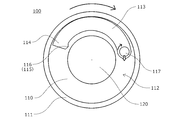
- the front sectional view of centrifugal clutch 100 concerning one embodiment of the present invention.
- the schematic front view which shows the state which the clutch lever 113 of the centrifugal clutch 100 which concerns on one Embodiment of this invention contacted the 2nd shaft member 120.
- the schematic front view which shows the state which the clutch lever 113 of the centrifugal clutch 100 which concerns on one Embodiment of this invention separated from the 2nd shaft member 120.
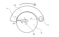
- FIG. 6 is a schematic diagram for explaining a power transmission relationship between a clutch lever CS and a second shaft member M.
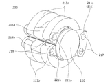
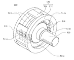
- FIG. The connecting pin 217 side perspective view of the centrifugal clutch 200 which concerns on one Embodiment of this invention.
- the perspective view of the rocking pin 218 side of centrifugal clutch 200 concerning one embodiment of the present invention.
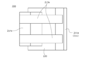
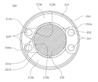
- the top view of the centrifugal clutch 200 which concerns on one Embodiment of this invention.
- the front view of the centrifugal clutch 200 which concerns on one Embodiment of this invention.
- the schematic front view which shows the state which the clutch lever 213 of the centrifugal clutch 200 which concerns on one Embodiment of this invention contact
- the schematic front view which shows the state which the clutch lever 213 of the centrifugal clutch 200 which concerns on one Embodiment of this invention separated from the 2nd shaft member 220. As shown in FIG. FIG. FIG.
- FIG. 3 is a schematic diagram showing a connection relationship between a clutch lever 313 and an outer ring connecting portion 311a of a centrifugal clutch 300 according to an embodiment of the present invention.
- FIG. 6 is a schematic diagram showing a connection relationship between a clutch lever 413 and a clutch shoe 414 of the centrifugal clutch 400 according to the embodiment of the present invention.
- the perspective view of the centrifugal clutch 500 which concerns on one Embodiment of this invention.
- the schematic front view of the centrifugal clutch 600 which concerns on one Embodiment of this invention.
- a centrifugal clutch 100 according to an embodiment of the present invention will be described below with reference to the drawings.
- a schematic diagram of a configuration in which only one clutch lever 113 is provided and the centrifugal clutch 100 functions only in clockwise rotation will be used from FIG. 2 onward.
- a centrifugal clutch 100 that is an embodiment of the present invention includes a first shaft member 110 and a second shaft member that is independently rotatable on the same rotation shaft as the first shaft member 110. 120 is provided, and the first shaft member 110 has an outer ring 111 having a cylindrical housing space 112 therein, a connecting pin 117 arranged in the housing space 112, and a rotating shaft via the connecting pin 117. And a clutch lever 113 connected to the first shaft member 110 so as to be relatively rotatable in a plane orthogonal to the above. The clutch levers 113 are arranged one by one in opposite directions with the second shaft member 120 interposed therebetween.
- the clutch lever 113 is inserted into the housing hole 118 opened to the outer ring 111 side and the housing hole 118, and the clutch lever 113 is inserted.
- An urging member 119 for urging the second shaft member 120 toward the second shaft member 120 with a slight force, and a clutch shoe 114 having a friction surface 115 configured to be capable of contacting the second shaft member 120 are provided.
- the power transmission relationship at the contact surface between the friction surface 115 of the clutch lever 113 and the second shaft member 120 is summarized in the power point 116 on the friction surface 115 to obtain the power transmission relationship at the power point 116. Can be replaced. Further, in the clutch lever 113, a line L1 connecting the force point 116 and the center of the connecting pin 117 and a line L2 connecting the force point 116 and the center of the second shaft member 120 have an inclination of an angle ⁇ . It is arranged. Further, the static friction coefficient ( ⁇ ) on the contact surface between the friction surface 115 of the clutch lever 113 and the second shaft member 120 is ⁇ >tan ⁇ To meet.
- the power transmission of the centrifugal clutch 100 at the start of rotation of the first shaft member 110 will be described.
- the outer ring 111 and the clutch lever 113 receive a force in a clockwise rotating direction.
- the clutch lever 113 is biased toward the second shaft member 120 side by the biasing member 119 with a slight force, the friction surface 115 of the clutch shoe 114 is changed when the first shaft member 110 starts rotating.
- the clutch lever 113 is in contact with the second shaft member 120, the clutch lever 113 can transmit power to the second shaft member 120 in the clockwise direction with respect to the force point 116. That is, the clutch lever 113 transmits the driving force (referred to as F1) in the direction of rotating the second shaft member 120 in the clockwise direction at the power point 116.
- F1 driving force
- the clutch lever 113 connects the second shaft member 120 at the power point 116.
- a vertical reaction force (not shown) having the same magnitude as the component force F2 and applied in the opposite direction is generated on the clutch lever 113 at the power point 116, so the maximum static friction force at the power point 116 is ⁇ F2.
- the clutch lever 113 can reliably transmit power to the second shaft member 120 without slipping. Further, due to the wedge effect, the clutch lever 113 maintains the state in which it is attracted to the second shaft member 120 side by the component force F2.
- the clutch lever 113 separated from the second shaft member 120 receives a force swung toward the outside of the centrifugal clutch 100, but the clutch lever 113 is arranged in the accommodation space 112 surrounded by the outer ring 111. Since the clutch lever 113 can move only to a position where it abuts the outer ring 111, the clutch lever 113 does not pop out around the centrifugal clutch 100, and it is not necessary to secure a large space around the centrifugal clutch 100.
- the centrifugal clutch 100 since there is no biasing member in the centrifugal clutch 100 other than the biasing member 119 that slightly biases the clutch lever 113 toward the second shaft member 120, the number of parts in the housing space 112 can be reduced, and It is not necessary to secure a large space in the centrifugal clutch 100, and the centrifugal clutch 100 can be downsized.
- the clutch lever 113 disengaged from the second shaft member 120 is urged toward the outer ring 111 side by the centrifugal force while the first shaft member 110 is rotating, so that the clutch lever 113 may come into contact with the second shaft member 120. Absent. Furthermore, it suffices to provide a weak biasing member to control the reconnection, which makes it extremely easy to control the torque transmission at a low rotation speed.
- the power is transmitted from the first shaft member 110 to the second shaft member 120 without the clutch lever 113 slipping further. Can be communicated.
- the centrifugal clutch 100 which is an embodiment of the present invention, it is desirable that the combined center of gravity of all the members forming the first shaft member 110 side be located on the rotation axis of the first shaft member 110 as much as possible. .. Thereby, the vibration of the first shaft member 110 can be suppressed during the operation of the centrifugal clutch 100, and the deviation between the rotation shaft of the first shaft member 110 and the rotation shaft of the second shaft member 120 can be prevented.
- the clutch lever 113 moves around the connecting pin 117 as the center of rotation during the operation of the centrifugal clutch 100 and comes into contact with or disengages from the second shaft member 120.
- the position of the composite center of gravity of all the members constituting the 110 side slightly changes. Therefore, in consideration of the moving position of the clutch lever 113 in the state where the vibration of the first shaft member 110 is most desired to be suppressed, the combined center of gravity of all the members forming the first shaft member 110 side is the rotation of the first shaft member 110. It is desirable to set it to match the axis.
- FIGS. 5 to 10 do not show the first shaft member 210 and the outer ring 211, and FIGS. 9 and 10 do not show the clutch lever 213b. Further, a part of the description common to the centrifugal clutch 100 according to the embodiment of the present invention will be omitted.
- a centrifugal clutch 200 that is an embodiment of the present invention includes a first shaft member 210 and a first shaft member 210 that is independently rotatable about the same rotation shaft as the first shaft member 210.
- the biaxial member 220 is provided, and the first shaft member 210 has an outer ring 211 having a housing space 212 inside, and a connection pin 217 having both ends supported by an outer ring connecting portion 211 a arranged in the housing space 212.
- the clutch levers 213a and 213b are connected to the first shaft member 210 via the connecting pin 217 so as to be relatively rotatable in a plane orthogonal to the rotation axis.
- the clutch levers 213a and 213b are provided two by two in opposite directions with the second shaft member 220 interposed therebetween in the rotation axis direction of the clutch levers 213a and 213b.
- a swing pin 218 having a swing shaft parallel to the shaft is connected, and clutch shoes 214a and 214b are connected to the swing pin 218 so as to be swingable about the swing shaft.
- the clutch shoes 214a, 214b are provided with linings 221a, 221b having friction surfaces 215a, 215b at the contact portions with the second shaft member 220, and formed in an arc shape along the outer peripheral surface of the second shaft member 220. Has been done. Further, the clutch levers 213a and 213b are biased by a biasing member (not shown) toward the second shaft member 220 with a slight force.
- the power transmission relationship at the contact surface between the friction surface 215a and the second shaft member 220 is concentrated at the power point 216 of the friction surface 215a, so that the power transmission at the power point 216 is transmitted. Can be replaced by a relationship.
- the friction surface 215a is in stable surface contact over a wide range by adjusting the inclination with respect to the outer peripheral surface of the second shaft member 220 by the swing pin 218.
- the clutch lever 213a has an angle between L1 and L2. It is arranged so as to have an inclination of ⁇ .
- the static friction coefficient (referred to as ⁇ ) at the contact surface between the friction surface 215a of the lining 221a and the second shaft member 220 is ⁇ >tan ⁇ To meet.
- the clutch lever 213a is biased by the biasing member (not shown) toward the second shaft member 220 side with a slight force. Therefore, at the start of rotation of the first shaft member 210, the friction surface of the lining 221a. 215a is in contact with the second shaft member 220, and the clutch lever 213a can transmit power to the second shaft member 220 in the clockwise rotation direction with reference to the force point 216. That is, the clutch lever 213a transmits the driving force (referred to as F1) in the direction of rotating the second shaft member 220 in the clockwise direction at the power point 216.
- F1 driving force
- the clutch shoe 214a is configured to be swingable with the center axis of the swing pin 218 as the swing axis, compared to the case where the clutch shoe 214a is directly and fixedly provided on the clutch lever 213a, the lining.
- the 221a can change its direction according to the outer peripheral surface of the second shaft member 220 and come into contact with the outer peripheral surface of the second shaft member 220, and the position of the force point 216 can be stably maintained. Further, the contact surface of the friction surface 215a with the second shaft member 220 can be made large, and the surface pressure applied to the friction surface 215a can be reduced.
- the clutch lever 213a causes the second shaft member 220 to move to the power point 216 at the power point 216.
- a normal force (not shown) having the same magnitude as the component force F2 and applied in the opposite direction is generated on the clutch shoe 214a at the force point 216, the maximum static friction force at the force point 216 is ⁇ F2.
- the clutch lever 213a can reliably transmit power to the second shaft member 220 without causing the friction surface 215a and the second shaft member 220 to slide. Further, due to the wedge effect, the clutch shoe 214a maintains the state of being attracted to the second shaft member 220 by the component force F2.
- two clutch levers 213a are connected to the outer ring connecting portion 211a side by side through the connecting pin 217 so as to be relatively rotatable relative to each other in a plane orthogonal to the rotation axis. Therefore, as compared with the case where only one clutch lever 213a is connected to the outer ring connecting portion 211a, the clutch lever 213a can stably rotate about the central axis of the connecting pin 217 and the shearing area of the connecting pin 217 becomes smaller. As a result, the shear stress of the connecting pin 217 decreases. As a result, the torque that can be transmitted can be increased without increasing the strength by changing the materials of the connecting pin 217, the clutch lever 213a, and the outer ring connecting portion 211a.
- a swing pin 218 having a swing shaft parallel to the rotation axis of the clutch lever 213a is connected to the two clutch levers 213a, and a clutch shoe 214a is centered around the swing shaft on the swing pin 218. Since only one clutch lever 213a is connected to the clutch shoe 214a, the clutch shoe 214a stably swings around the central axis of the swing pin 218 as compared with the case where only one clutch lever 213a is connected to the clutch shoe 214a. At the same time, the shear area of the swing pin 218 increases, and the shear stress of the swing pin 218 decreases. As a result, the torque that can be transmitted can be further increased without increasing the strength by changing the materials of the swing pin 218, the clutch lever 213a, and the clutch shoe 214a.
- the clutch shoe 214a can be stably supported at a plurality of points by the clutch lever 213a. Further, since both ends of the connecting pin 217 are supported by the outer ring connecting portion 211a, the shearing area of the connecting pin 217 increases and the shear stress decreases, and the clutch lever 213a and the outer ring connecting portion 211a are operated during the operation of the clutch 200. Even if a force is applied in the bending direction of the connecting pin 217, the connecting pin 217 is unlikely to be deformed, and the clutch lever 213a can be reliably supported at a normal position.
- centrifugal clutch 500 according to an embodiment of the present invention will be described with reference to FIG.
- a part of the description common to the centrifugal clutch 100 and the centrifugal clutch 200 according to the embodiment of the present invention will be omitted.
- a centrifugal clutch 500 includes a first shaft member 510 and a second shaft member that is independently rotatable on the same rotation shaft as the first shaft member 510. And 520 are provided.
- One end of a connecting member 511a formed separately from the first shaft member 510 is directly connected to the first shaft member 510, and both ends of the clutch levers 513a and 513b are supported by the connecting member 511a. It is connected to the first shaft member 510 via a pin (not shown) so as to be relatively rotatable in a plane orthogonal to the rotation axis.
- connection member 511 a Of the end portions of the connection member 511 a, the end portion on the side not directly connected to the first shaft member 510 is fixed to the first shaft member 510 via the reinforcing member 530. That is, both ends of the connecting member 511a are fixed to the first shaft member 510.
- the reinforcing member 530 includes a reinforcing ring 532 that is directly connected to the end of the connecting member 511a, and a reinforcing column 531 that connects the first shaft member 510 and the reinforcing ring 532.
- the stress applied to the connecting member 511a during the operation of the centrifugal clutch 500 can be dispersed from the both ends of the connecting member 511a to the first shaft member 510, and the deflection of the first shaft member 510 and the connecting member 511a can be reduced.
- the positional relationship between the member 510 and the clutch levers 513a and 513b can be prevented from shifting, and stable torque transmission can be performed.
- the reinforcing member 530 connects the reinforcing ring 531 and the first shaft member 510 with the plurality of reinforcing columns 532 arranged along the outer edge of the first shaft member 510, the stress applied to the connecting member 511a is It is possible to disperse the first shaft member 510 as a whole, it is possible to further prevent the displacement of the positional relationship between the first shaft member 510 and the clutch levers 513a, 513b, and it is possible to further stably transmit the torque.
- FIG. 14 does not show the first shaft member and the connecting member. Further, a part of the description common to the centrifugal clutches 100, 200, and 500 according to the embodiment of the present invention will be omitted.
- a centrifugal clutch 600 is configured to be independently rotatable on a first shaft member (not shown) and the same rotation shaft as the first shaft member (not shown).
- Second shaft member 620 is provided.
- An end of a connection member (not shown) is connected to the first shaft member (not shown), and both ends of the forward rotation side clutch lever 613a and the reverse rotation side clutch lever 613b are supported by the connection member (not shown). It is connected to the first shaft member (not shown) so as to be relatively rotatable in the plane orthogonal to the rotation axis via the connecting pin.
- a gear protrusion 631 is provided at an end of the forward rotation side clutch lever 613a supported by the connection pin 617, and a gear protrusion 631 is provided at an end of the reverse rotation side clutch lever 613b supported by the connection pin 617.
- the interlocking gear 630 is formed by meshing with the gear recessed portion 632. By this interlocking gear 630, the forward rotation side clutch lever 613a and the reverse rotation side clutch lever 613b rotate in the opposite direction about the connecting pin 617 as the center of rotation, and therefore, for example, the friction surface 615a of the forward rotation side clutch lever 613a.
- the friction surface 615b of the reverse rotation side clutch lever 613b also interlocks and disengages from the second shaft member 620 almost at the same time, so that abrasion of the friction surfaces 615a and 615b can be suppressed and the torque transmission. Switching can be performed quickly.
- the forward rotation side clutch lever and the reverse rotation side clutch lever always have their own weights in the direction in which gravity acts.
- gravity acts in the direction in which the forward rotation side clutch lever contacts the second shaft member
- gravity acts in the direction away from the second shaft member in the reverse rotation side clutch lever.
- the contact and release timings of the forward rotation side clutch lever and the reverse rotation side clutch lever with respect to the second shaft member may become unstable.
- the forward rotation side clutch lever 613a and the reverse rotation side clutch lever 613b of the centrifugal clutch 600 are configured to be interlocked with each other by the interlocking gear 630, the forward rotation side clutch lever 613a and the reverse rotation side clutch lever 613b can be rotated together with the gear protrusion 631.
- the weights of the forward rotation side clutch lever 613a and the reverse rotation side clutch lever 613b can be canceled each other through the gear recess 632, and the second shaft member 620 of the forward rotation side clutch lever 613a and the reverse rotation side clutch lever 613b can be canceled. There is no disruption in the timing of contact and release.
- the clutch levers are described as being arranged one by one in opposite directions with the second shaft member interposed therebetween, but the number and arrangement direction of the clutch levers are not limited to this, and for example, Only one clutch lever may be arranged in the forward rotation direction of the second shaft member, or two clutch levers may be arranged in opposite directions with the second shaft member interposed therebetween.
- the clutch lever has the accommodation hole opened to the outer ring side and the urging member that is inserted into the accommodation hole and urges the clutch lever toward the second shaft member with a slight force.
- the aspect of the clutch lever is not limited to this, and for example, the accommodation hole or the urging member may not be provided, and the urging member is provided from the accommodation hole provided in the outer ring to the clutch. It may be arranged to bias the lever.
- first shaft member and the second shaft member are described as being rotatably opposed to each other independently of each other about the same rotation shaft as the central axis, but the first shaft member is described.
- the arrangement of the second shaft member and the second shaft member is not limited to this.
- the second shaft member may be arranged to be inserted into the hollow cylindrical first shaft member.
- the clutch lever is described as being connected to the outer ring connecting portion side by side so as to be relatively rotatable in the plane orthogonal to the rotation axis via the connecting pin.
- the number of levers is not limited to this, and, for example, three levers may be connected side by side to the outer ring connecting portion so as to be relatively axially rotatable in a plane orthogonal to the rotation axis via a connecting pin.
- the clutch lever is described as being connected to the outer ring connecting portion side by side so as to be relatively rotatable in the plane orthogonal to the rotation axis via the connecting pin.
- the connection state of the lever and the outer ring connecting portion is not limited to this.
- the connecting portion of the clutch levers 313a and 313b with the connecting pin 317 is formed in a comb shape.
- the outer ring connecting portion side may also be formed in a comb shape so as to match the connecting portion of the clutch lever formed in a comb shape with the connecting pin.
- the clutch lever is connected to the swing pin having the swing shaft parallel to the rotation axis of the clutch lever, and the clutch shoe is connected to the swing pin about the swing shaft.
- the clutch levers 413a and 413b are not connected to each other, for example, as in the centrifugal clutch 400 shown in FIG.
- the clutch levers 413a and 413b may be formed in a comb shape at the connecting portion with the rocking pins 413a and 413b.
- the clutch shoe side may also be formed in a comb shape in accordance with the connection portion of the above.
- the clutch shoe is provided with a lining having a friction surface at the contact portion with the second shaft member, and is formed in an arc shape along the outer peripheral surface of the second shaft member.
- the configuration of the clutch shoe is not limited to this, and for example, the lining may not be provided, the clutch shoe may be formed in a flat plate shape, and the lining capable of being deformed by a certain amount may have a predetermined thickness. It may be attached to the clutch shoe, and the lining may be deformed at the time of contact with the outer peripheral surface of the second shaft member to form a wide friction surface.
- the first shaft member includes the outer ring having the accommodation space therein, the connection pins whose both ends are supported by the outer ring connection portion disposed in the accommodation space, and the rotating shaft via the connection pin.
- the clutch lever that is connected to the first shaft member so as to be relatively rotatable in the plane orthogonal to the above has been described, but the configuration of each member provided in the first shaft member is the same.
- the connection pins may be provided so that both ends are directly supported by the first shaft member without providing the outer ring or the outer ring connecting portion.
- the reinforcing member has been described as being configured by the ring-shaped reinforcing ring and the reinforcing column, but the configuration of the reinforcing member is not limited to this, and for example, two reinforcing columns are provided.
- the first shaft member extends in a direction along the rotation axis from the first shaft member so as to sandwich the connection member, and connects the end portion of the connection member and the end portion of the reinforcing column with a rod-shaped connecting member instead of the reinforcing ring.
- the reinforcing member may be fixed to the end portion of the connection member and the end portion of the first shaft member so as to sandwich the connection member and the first shaft member from the rotation axis direction.
- connection member is configured such that one end of the connection member is directly connected to the first shaft member and the other end is connected to the first shaft member via the reinforcing member.
- connection form of the connection member and the first shaft member is not limited to this, and for example, one end of the connection member is directly connected to the first shaft member, and a position other than the end of the connection member is provided. May be connected to the first shaft member via the reinforcing member, or the connecting member, the first shaft member, and a part or all of the reinforcing member may be integrally formed.
- connection member is positioned and connected to the first shaft member by providing the end portion of the connection pin on the first shaft member side so as to penetrate the connection member and connecting the connection pin to the first shaft member. It may be configured to do so.
- the gear convex portion is provided at the end supported by the connecting pin of the forward rotation side clutch lever, and the gear convex portion is provided at the end supported by the connection pin of the reverse rotation side clutch lever.
- the description has been given assuming that the gears mesh with the provided gear recesses to form the interlocking gears and rotate in conjunction with each other, but the relationship between the forward rotation side clutch lever and the reverse rotation side clutch lever is not limited to this.
- the forward rotation side clutch lever and the reverse rotation side clutch lever do not have to rotate in conjunction without providing an interlocking gear, and the side supported by the connecting pin of the forward rotation side clutch lever and the reverse rotation side clutch lever.
- the forward rotation side clutch lever and the reverse rotation side clutch lever may be configured to rotate interlocked with each other by coating the surface of the end portion with a rubber material and bringing them into contact with each other.
- Centrifugal clutch 110 210, 510... 1st shaft member 111, 211... Outer ring 211a, 311a... Outer ring connection part 511a... Connection member 112, 212... Accommodation spaces 113, 213a, 213b, 313a, 313b, 413a, 413b, 513a, 513b, CS... Clutch lever 613a... Forward rotation side clutch lever 613b... Reverse rotation side clutch lever 114, 214a, 214b, 314a, 314b, 414a, 414b, 514a, 514b, 614a, 614b...
Landscapes
- Engineering & Computer Science (AREA)
- General Engineering & Computer Science (AREA)
- Mechanical Engineering (AREA)
- One-Way And Automatic Clutches, And Combinations Of Different Clutches (AREA)
Abstract
簡単な構成で、クラッチシューを第2軸部材に当接でき、伝達トルクが低下することを抑制でき、小型化が可能且つ製造コストの増加を抑制可能な遠心クラッチを提供すること。 第1軸部材(110)と、第2軸部材(120)と、第2軸部材(120)に当接可能な摩擦面(115)を有するクラッチレバー(113)とが設けられた遠心クラッチ(100)であって、摩擦面(115)と第2軸部材(120)とが当接した状態で、接続ピン(117)の中心から摩擦面(115)の力点(116)までを結んだ線と、第2軸部材(120)の中心から力点(116)までを結んだ線とがなす角度をθとし、摩擦面(115)と第2軸部材(120)とが当接した際の静止摩擦係数をμとしたとき、 μ>tanθ であるように配置されていること。
Description
本発明は、入力軸の回転を出力軸側に伝達するクラッチに関し、特に、遠心力によって入力軸から出力軸への動力の伝達および切断を切り替える遠心クラッチに関する。
従来、入力軸から出力軸側に動力伝達するクラッチは、小型バイク、チェーンソー、エンジン式ラジコンヘリ等の小型の駆動機器等の駆動力の伝達経路上に配されており、様々なものが公知である。
例えば、特許文献1に記載の遠心クラッチは、第1軸部材(入力側回転部1)と第2軸部材(出力側ドラム5)とを有し、第1軸部材(入力側回転部1)には、接続ピン(支軸3)を介して一対のクラッチレバー(摩擦シュー2)および遠心ウェイト7が接続されており、一対のクラッチレバー(摩擦シュー2)は、第2軸部材(出力側ドラム5)に向かって摩擦面を付勢するように、互いの一端がクラッチスプリング4で接続されている。
一対の遠心ウェイト7は、第2軸部材(出力側ドラム5)を抱合する方向に、ウェイトスプリング8により、互いの側面を付勢されている。
また、遠心ウェイト7は、互いの自由端側に形成されたカム面9が第1軸部材(入力側回転部1)に接続されたディテントスプリング10に係合しているものである。
一対の遠心ウェイト7は、第2軸部材(出力側ドラム5)を抱合する方向に、ウェイトスプリング8により、互いの側面を付勢されている。
また、遠心ウェイト7は、互いの自由端側に形成されたカム面9が第1軸部材(入力側回転部1)に接続されたディテントスプリング10に係合しているものである。
この特許文献1に記載の遠心クラッチは、クラッチスプリング4によってクラッチレバー(摩擦シュー2)の摩擦面が第2軸部材(出力側ドラム5)に密着しているため、第1軸部材(入力側回転部1)を回転させると、第2軸部材(出力側ドラム5)に動力伝達されるが、徐々に第1軸部材(入力側回転部1)の回転数が上がり遠心力が大きくなるにしたがって、クラッチスプリング4の付勢力との差が縮まり、クラッチレバー(摩擦シュー2)の摩擦面が第2軸部材(出力側ドラム5)から離脱する方向に力がかかるようになる。
また、遠心ウェイト7も遠心力によって徐々にディテントスプリング10およびウェイトスプリング8を押し返しながら拡開し、さらに、ディテントスプリング10とカム面9との係合が解除されると、遠心ウェイト7の所定の位置に設けられた係合ピン11がクラッチレバー(摩擦シュー2)に接触し、クラッチレバー(摩擦シュー2)を第2軸部材(出力側ドラム5)から離脱させ、第1軸部材(入力側回転部1)から第2軸部材(出力側ドラム5)への動力伝達を解除するものである。
なお、クラッチスプリング4、ウェイトスプリング8、ディテントスプリング10の調整で、クラッチレバー(摩擦シュー2)の離脱タイミングを変化させることができるものである。
なお、クラッチスプリング4、ウェイトスプリング8、ディテントスプリング10の調整で、クラッチレバー(摩擦シュー2)の離脱タイミングを変化させることができるものである。
ところが、上記特許文献等で公知の遠心クラッチは、未だ改善の余地があった。
発明者は、鋭意検討の結果、遠心クラッチが回転した際の、クラッチレバーと第2軸部材との当接時の力の伝達関係について、以下に説明する知見を得た。
遠心クラッチの第1軸部材が回転すると、図4に示すように、クラッチシューCSの摩擦面が第2軸部材Mと当接して発生する摩擦力は、摩擦面内の力点Pに集約して示すことができる。
このとき、摩擦面内の力点Pにおいて、クラッチレバーCSは駆動力F1で第2軸部材Mを回転させようとするが、その際、駆動力F1は力点Pから接続ピンSの方向へ引く力Fの分力として発生しているため、クラッチレバーCSは力点Pにおいて第2軸部材Mを接続ピンSの方向に力Fで押していることになる。
すなわち、第2軸部材Mは力点Pにおいて、回転方向に駆動力F1を受けるとともに、第2軸部材Mの中心軸MS方向にFの分力F2で押されていることになり、同時にシューCSには接点PにおいてF2と同じ大きさで反対向きにかかる垂直抗力(図示しない)が発生している。
このとき、摩擦面内の力点Pにおいて、クラッチレバーCSは駆動力F1で第2軸部材Mを回転させようとするが、その際、駆動力F1は力点Pから接続ピンSの方向へ引く力Fの分力として発生しているため、クラッチレバーCSは力点Pにおいて第2軸部材Mを接続ピンSの方向に力Fで押していることになる。
すなわち、第2軸部材Mは力点Pにおいて、回転方向に駆動力F1を受けるとともに、第2軸部材Mの中心軸MS方向にFの分力F2で押されていることになり、同時にシューCSには接点PにおいてF2と同じ大きさで反対向きにかかる垂直抗力(図示しない)が発生している。
また、クラッチレバーCSと第2軸部材Mとが力点Pで接触しているため、クラッチレバーCSと第2軸部材Mとの間の静止摩擦係数をμとすると、最大静止摩擦力はμF2である。
よって、
μF2>F1
であれば、クラッチレバーCSをスプリングなどで押圧しなくても、クラッチレバーCSは滑ることなく第2軸部材Mに動力伝達できる。
よって、
μF2>F1
であれば、クラッチレバーCSをスプリングなどで押圧しなくても、クラッチレバーCSは滑ることなく第2軸部材Mに動力伝達できる。
ただし、遠心クラッチは回転しているため、遠心力に起因して力点Pから垂直抗力と同じ方向にFr(図示しない)が発生しており、遠心クラッチの回転速度が上昇するにしたがってFr(図示しない)も大きくなるため、実際には、
μ(F2-Fr)>F1
を維持している間、シューCSは滑ることなく第2軸部材Mに動力伝達できる。
μ(F2-Fr)>F1
を維持している間、シューCSは滑ることなく第2軸部材Mに動力伝達できる。
さらに、力点Pと接続ピンSを結んだ線L1と、力点Pと第2軸部材Mの中心軸MSとを結んだ線L2とがなす角を角度θとすると、
F1=Fsinθ
F2=Fcosθ
であるから、
F2=F1/tanθ
となり、θが小さいほどF1に対してF2が大きくなる。
すなわち、より回転速度が速くなっても
μ(F2-Fr)>F1
を維持することができ、高速回転中でも滑ることなく動力伝達できる。
F1=Fsinθ
F2=Fcosθ
であるから、
F2=F1/tanθ
となり、θが小さいほどF1に対してF2が大きくなる。
すなわち、より回転速度が速くなっても
μ(F2-Fr)>F1
を維持することができ、高速回転中でも滑ることなく動力伝達できる。
また、回転開始時においては、
μF2>F1
より、
μ>tanθ
であれば、力点Pにおける摩擦係数μに合わせて適切な角度θをなすようにクラッチレバーCSを配置する、もしくは、角度θに合わせて力点Pに適切な摩擦係数μを有するようにクラッチレバーCSの摩擦面や第2軸部材Mの表面を形成することで、クラッチレバーCSが滑ることなく第2軸部材Mに動力伝達できる。
μF2>F1
より、
μ>tanθ
であれば、力点Pにおける摩擦係数μに合わせて適切な角度θをなすようにクラッチレバーCSを配置する、もしくは、角度θに合わせて力点Pに適切な摩擦係数μを有するようにクラッチレバーCSの摩擦面や第2軸部材Mの表面を形成することで、クラッチレバーCSが滑ることなく第2軸部材Mに動力伝達できる。
ここで、特許文献1で公知の遠心クラッチは、摩擦シューと出力側ドラムとの接触面が出力側ドラムの円周方向に広範囲に分布しており、力点Pの位置が接続ピンS側に近づき、角度θが大きくなってしまうため、F1とF2との差が小さくなり、回転速度が上昇すると、すぐに、
μ(F2-Fr)≦F1
となり、摩擦シューと出力側ドラムとの当接が解除されてしまう。
μ(F2-Fr)≦F1
となり、摩擦シューと出力側ドラムとの当接が解除されてしまう。
摩擦シューや出力側ドラムの材質を変更して静止摩擦係数μを上昇させることで、摩擦シューと出力側ドラムとの当接を維持することも考えられるが、摩擦面は既に一定以上の静止摩擦係数が発生するような仕様であるため、静止摩擦係数を上昇させる余地は少ない。
したがって、摩擦シューを出力側ドラム側へ強く押圧するための付勢部材が事実上必須要素となっており、付勢部材を格納するための空間を遠心クラッチ内に確保する必要があった。
したがって、摩擦シューを出力側ドラム側へ強く押圧するための付勢部材が事実上必須要素となっており、付勢部材を格納するための空間を遠心クラッチ内に確保する必要があった。
すなわち、特許文献1で公知の遠心クラッチは、クラッチスプリングによって摩擦シューを出力側ドラムへ押し付け、さらに、ディテントスプリング、ウェイトスプリングによって遠心ウェイトの離脱タイミングを調整することで摩擦シューの離脱タイミングを変化させているが、クラッチスプリング、ディテントスプリング、ウェイトスプリングを設けるための空間が遠心クラッチ内に必要となり、遠心クラッチが複雑化し大型化してしまう虞があった。
また、入力側回転部の回転数が上昇して遠心力が大きくなり、クラッチスプリングの付勢力との差が縮まると、摩擦シューと出力側ドラムとの接触状態が、静止摩擦状態から動摩擦状態へ移行してしまい、摩擦シューが出力側ドラム上で滑り始め、伝達トルクが低下してしまう虞があった。
また、入力側回転部の回転数が上昇しても摩擦シューと出力側ドラムとの接触状態を静止摩擦状態のままにするには、より強力なクラッチスプリングを設ける必要があり、強力なクラッチスプリングの引張力に耐えられる特別強固な材料を使用することになるため、製造コストが増大してしまう虞があった。
さらに、所定の回転数以下で再び摩擦面が接触するため、回転数が低い状態でトルクの伝達のコントロールが難しいという問題があった。
また、入力側回転部の回転数が上昇して遠心力が大きくなり、クラッチスプリングの付勢力との差が縮まると、摩擦シューと出力側ドラムとの接触状態が、静止摩擦状態から動摩擦状態へ移行してしまい、摩擦シューが出力側ドラム上で滑り始め、伝達トルクが低下してしまう虞があった。
また、入力側回転部の回転数が上昇しても摩擦シューと出力側ドラムとの接触状態を静止摩擦状態のままにするには、より強力なクラッチスプリングを設ける必要があり、強力なクラッチスプリングの引張力に耐えられる特別強固な材料を使用することになるため、製造コストが増大してしまう虞があった。
さらに、所定の回転数以下で再び摩擦面が接触するため、回転数が低い状態でトルクの伝達のコントロールが難しいという問題があった。
本発明は、これらの問題点を解決するものであり、簡単な構成で、クラッチシューを第2軸部材に当接でき、伝達トルクが低下することを抑制でき、小型化が可能且つ製造コストの増加を抑制可能な遠心クラッチを提供することを目的とするものである。
本発明の遠心クラッチは、第1軸部材および前記第1軸部材と同一の回転軸で独立して回転可能に構成された第2軸部材とを有し、前記第1軸部材には、接続ピンを介して回転軸と直交する面内で相対的に軸回転可能に接続されたクラッチレバーが設けられ、前記クラッチレバーには、前記第2軸部材に外周側から当接可能に構成された摩擦面を有したクラッチシューが設けられた遠心クラッチであって、前記摩擦面と前記第2軸部材とが当接した状態における、前記接続ピンの中心から前記摩擦面の力点までを結んだ線と、前記第2軸部材の中心から前記摩擦面の力点までを結んだ線とがなす角度をθとし、前記摩擦面と前記第2軸部材とが当接した際の静止摩擦係数をμとしたとき、
μ>tanθ
であるように配置されていることにより、前記課題を解決するものである。
μ>tanθ
であるように配置されていることにより、前記課題を解決するものである。
請求項1にかかる発明の遠心クラッチは、第1軸部材には、接続ピンを介して回転軸と直交する面内で相対的に軸回転可能に接続されたクラッチレバーが設けられ、クラッチレバーには、第2軸部材に外周側から当接可能に構成された摩擦面を有したクラッチシューが設けられた遠心クラッチであって、摩擦面と第2軸部材とが当接した状態における、接続ピンの中心から摩擦面の力点までを結んだ線と、第2軸部材の中心から摩擦面の力点までを結んだ線とがなす角度をθとし、摩擦面と第2軸部材とが当接した際の静止摩擦係数をμとしたとき、
μ>tanθ
であるように配置されているため、クラッチシューの摩擦面が第2軸部材に当接した状態で第1軸部材を回転させると、クラッチレバーは滑ることなく確実に第2軸部材に動力を伝達できる。
また、スプリングの押し付けによる摩擦力ではなく、くさび効果による噛み込みを利用した摩擦力による動力伝達であるため、伝達トルクを大きくできる。
さらに、遠心クラッチの回転数が上昇すると遠心力を起因としたFrが大きくなり、
μ(F2-Fr)≦F1
を満たすと、瞬時にクラッチレバーは第2軸部材から離脱するため、クラッチレバーと第2軸部材とが滑りながら当接する時間が短くなり、クラッチシューや第2軸部材の摩耗が少なく、メンテンナンス頻度を少なくできる。
また、スプリングの押し付けによる摩擦力を必要としないため、遠心クラッチ内に摩擦力発生用のスプリングを設置する空間を設ける必要がなく、遠心クラッチを小型化できる。
さらに、再接続をコントロールするために弱いスプリングを設けるだけでよく、回転数が低い状態でトルクの伝達のコントロールがきわめて容易となる。
μ>tanθ
であるように配置されているため、クラッチシューの摩擦面が第2軸部材に当接した状態で第1軸部材を回転させると、クラッチレバーは滑ることなく確実に第2軸部材に動力を伝達できる。
また、スプリングの押し付けによる摩擦力ではなく、くさび効果による噛み込みを利用した摩擦力による動力伝達であるため、伝達トルクを大きくできる。
さらに、遠心クラッチの回転数が上昇すると遠心力を起因としたFrが大きくなり、
μ(F2-Fr)≦F1
を満たすと、瞬時にクラッチレバーは第2軸部材から離脱するため、クラッチレバーと第2軸部材とが滑りながら当接する時間が短くなり、クラッチシューや第2軸部材の摩耗が少なく、メンテンナンス頻度を少なくできる。
また、スプリングの押し付けによる摩擦力を必要としないため、遠心クラッチ内に摩擦力発生用のスプリングを設置する空間を設ける必要がなく、遠心クラッチを小型化できる。
さらに、再接続をコントロールするために弱いスプリングを設けるだけでよく、回転数が低い状態でトルクの伝達のコントロールがきわめて容易となる。
請求項2に記載の構成によれば、クラッチレバーは、第2軸部材を挟んで逆向きに少なくとも1つずつ配置されているため、第1軸部材の回転方向が正逆どちらであっても、それぞれに対応したクラッチレバーが第2軸部材に当接し、動力を伝達することができる。
請求項3に記載の構成によれば、クラッチレバーは、付勢部材によって第2軸部材側に付勢されているため、第1軸部材が回転を始める際に確実にクラッチレバーを第2軸部材に当接させておくことができる。
請求項3に記載の構成によれば、クラッチレバーは、付勢部材によって第2軸部材側に付勢されているため、第1軸部材が回転を始める際に確実にクラッチレバーを第2軸部材に当接させておくことができる。
請求項4に記載の構成によれば、付勢部材は、第2軸部材を挟んで逆向きに少なくとも1つずつ配置されているクラッチレバーに挟持されているため、付勢部材の設置数を削減できるとともに、遠心クラッチを小型化できる。
請求項5に記載の構成によれば、第1軸部材には、内部に円筒状の収容空間を有した外輪が設けられ、接続ピンは、収容空間内に配置されているため、遠心クラッチの回転数が上昇してクラッチシューが第2軸部材から離脱しても、クラッチレバーは収容空間内の最外部へぶつかるため、クラッチレバーが収容空間外へ大きく振り回されることがなくなり、遠心クラッチの周囲に大きな空間を設ける必要がない。
請求項5に記載の構成によれば、第1軸部材には、内部に円筒状の収容空間を有した外輪が設けられ、接続ピンは、収容空間内に配置されているため、遠心クラッチの回転数が上昇してクラッチシューが第2軸部材から離脱しても、クラッチレバーは収容空間内の最外部へぶつかるため、クラッチレバーが収容空間外へ大きく振り回されることがなくなり、遠心クラッチの周囲に大きな空間を設ける必要がない。
請求項6に記載の構成によれば、クラッチレバーおよび第1軸部材の少なくともいずれか一方は、クラッチレバーの回転軸方向に複数箇所で接続ピンと接続されているため、接続ピンのせん断面積が増えることで、接続ピンのせん断応力が小さくなり、これによって、接続ピンクラッチレバー、外輪の材質を変えることなく、伝達可能なトルクを増大させることができる。
請求項7に記載の構成によれば、接続ピンは、第1軸部材に両端が支持されているため、クラッチレバーや外輪から接続ピンの曲げ方向に力がかかっても変形しにくく、クラッチレバーを確実に正常な位置で支持できる。
請求項7に記載の構成によれば、接続ピンは、第1軸部材に両端が支持されているため、クラッチレバーや外輪から接続ピンの曲げ方向に力がかかっても変形しにくく、クラッチレバーを確実に正常な位置で支持できる。
請求項8に記載の構成によれば、クラッチレバーの接続ピンとの接続箇所は、接続ピン側に開放された櫛状に形成されているため、接続ピンのせん断面積をさらに増加でき、接続ピンのせん断応力をより一層小さくできることで、伝達可能なトルクをさらに増大させることができる。
請求項9に記載の構成によれば、クラッチレバーは、接続ピンの軸方向に複数設けられているため、クラッチレバーの数を変えることで、接続ピンのせん断面積を簡単に調整できることから、せん断応力を小さくでき、これによって、より一層伝達可能なトルクを増大させることができる。
請求項9に記載の構成によれば、クラッチレバーは、接続ピンの軸方向に複数設けられているため、クラッチレバーの数を変えることで、接続ピンのせん断面積を簡単に調整できることから、せん断応力を小さくでき、これによって、より一層伝達可能なトルクを増大させることができる。
請求項10に記載の構成によれば、接続部材は、回転軸方向に沿った一方の端部が第1軸部材の端部に固定され、端部から離れた位置で補強部材を介して第1軸部材の端部に固定されているため、接続部材にかかる応力を分散することができ、接続部材の一方の端部のみ第1軸部材に固定している場合と比べて、第1軸部材や接続部材のたわみを低減することができる。
これによって、第1軸部材とクラッチレバーとの位置関係がずれることがなく、安定したトルク伝達が可能となる。
請求項11に記載の構成によれば、クラッチレバーが移動可能な範囲の所定の位置にあるとき、第1軸部材側を構成する全ての部材の合成重心が、第1軸部材の回転軸上に位置するため、遠心クラッチの回転動作による第1軸部材の振動を抑制し、第1軸部材の回転軸と第2軸部材の回転軸とのズレを防止できる。
これによって、第1軸部材とクラッチレバーとの位置関係がずれることがなく、安定したトルク伝達が可能となる。
請求項11に記載の構成によれば、クラッチレバーが移動可能な範囲の所定の位置にあるとき、第1軸部材側を構成する全ての部材の合成重心が、第1軸部材の回転軸上に位置するため、遠心クラッチの回転動作による第1軸部材の振動を抑制し、第1軸部材の回転軸と第2軸部材の回転軸とのズレを防止できる。
請求項12に記載の構成によれば、正回転側クラッチレバーと逆回転側クラッチレバーとは、互いに接続ピンを回転中心として逆方向に連動回転するため、例えば、一方のクラッチレバーの摩擦面が第2軸部材から離脱すると、他方のクラッチレバーの摩擦面も連動してほぼ同時に第2軸部材から離脱するため、摩擦面の摩耗を抑制でき、トルク伝達の切り替えを迅速に実施できる。
また、重力によるクラッチレバーの自重がクラッチレバーに対してどの方向にかかっても、互いに連動回転する正回転側クラッチレバーと逆回転側クラッチレバーとの間でクラッチレバーの自重を相殺できるため、遠心クラッチの回転方向の向きに関わらず、正回転側クラッチレバーと逆回転側クラッチレバーの動作をさらに安定化できる。
また、重力によるクラッチレバーの自重がクラッチレバーに対してどの方向にかかっても、互いに連動回転する正回転側クラッチレバーと逆回転側クラッチレバーとの間でクラッチレバーの自重を相殺できるため、遠心クラッチの回転方向の向きに関わらず、正回転側クラッチレバーと逆回転側クラッチレバーの動作をさらに安定化できる。
以下に本発明の一実施形態に係る遠心クラッチ100について、図面に基づいて説明する。
なお、説明のため、図2以降はクラッチレバー113を一つのみ設けた、時計回りの回転でのみ遠心クラッチ100が機能する構成の概略図を使用する。
なお、説明のため、図2以降はクラッチレバー113を一つのみ設けた、時計回りの回転でのみ遠心クラッチ100が機能する構成の概略図を使用する。
本発明の一実施形態である遠心クラッチ100は、図1に示すように、第1軸部材110および第1軸部材110と同一の回転軸で独立して回転可能に構成された第2軸部材120とが設けられ、第1軸部材110には、内部に円筒状の収容空間112を有した外輪111と、収容空間内112に配置された接続ピン117と、接続ピン117を介して回転軸と直交する面内で相対的に軸回転可能に第1軸部材110に接続されたクラッチレバー113とが設けられている。
クラッチレバー113は、第2軸部材120を挟んで逆向きに1つずつ配置され、クラッチレバー113には、外輪111側に開放された収容穴118と、収容穴118に挿入され、クラッチレバー113を第2軸部材120側に僅かな力で付勢する付勢部材119と、第2軸部材120に当接可能に構成された摩擦面115を有したクラッチシュー114とが設けられている。
クラッチレバー113は、第2軸部材120を挟んで逆向きに1つずつ配置され、クラッチレバー113には、外輪111側に開放された収容穴118と、収容穴118に挿入され、クラッチレバー113を第2軸部材120側に僅かな力で付勢する付勢部材119と、第2軸部材120に当接可能に構成された摩擦面115を有したクラッチシュー114とが設けられている。
なお、クラッチレバー113の摩擦面115と第2軸部材120との当接面での動力の伝達関係は、摩擦面115上の力点116に集約することで、力点116での動力の伝達関係に置き換えることができる。
また、クラッチレバー113は、力点116と接続ピン117の中心とを結んだ線L1と、力点116と第2軸部材120の中心とを結んだ線L2とが、角度θの傾きを有するように配置されている。
また、クラッチレバー113の摩擦面115と第2軸部材120との当接面における静止摩擦係数(μとする)は、
μ>tanθ
を満たすものである。
また、クラッチレバー113は、力点116と接続ピン117の中心とを結んだ線L1と、力点116と第2軸部材120の中心とを結んだ線L2とが、角度θの傾きを有するように配置されている。
また、クラッチレバー113の摩擦面115と第2軸部材120との当接面における静止摩擦係数(μとする)は、
μ>tanθ
を満たすものである。
次に、本発明の遠心クラッチ100の、第1軸部材110を回転させた際の動作について、図2乃至図4を用いて説明する。
まず、第1軸部材110の回転開始時における遠心クラッチ100の動力伝達について説明する。
第1軸部材110が時計回りに回転を始めると、図2に示すように、外輪111およびクラッチレバー113は時計回りに回転する方向へ力を受ける。
このとき、付勢部材119によって、クラッチレバー113は第2軸部材120側に僅かな力で付勢されているため、第1軸部材110の回転開始時において、クラッチシュー114の摩擦面115は第2軸部材120に当接しており、クラッチレバー113は力点116を基準として、第2軸部材120に対して時計回りへ回転する方向へ動力を伝達することができる。
すなわち、クラッチレバー113は、力点116で第2軸部材120を時計回りへ回転する方向へ駆動力(F1とする)を伝達している。
第1軸部材110が時計回りに回転を始めると、図2に示すように、外輪111およびクラッチレバー113は時計回りに回転する方向へ力を受ける。
このとき、付勢部材119によって、クラッチレバー113は第2軸部材120側に僅かな力で付勢されているため、第1軸部材110の回転開始時において、クラッチシュー114の摩擦面115は第2軸部材120に当接しており、クラッチレバー113は力点116を基準として、第2軸部材120に対して時計回りへ回転する方向へ動力を伝達することができる。
すなわち、クラッチレバー113は、力点116で第2軸部材120を時計回りへ回転する方向へ駆動力(F1とする)を伝達している。
また、駆動力F1は、力点116から接続ピン117の中心軸に向かって引く力(Fとする)の分力として発生しているため、クラッチレバー113は力点116において第2軸部材120を接続ピン117の中心軸の方向に力Fで押していることになる。
すなわち、第2軸部材120は、力点116において回転方向に駆動力F1(=Fsinθ)を受けるとともに、第2軸部材120の中心軸の方向に分力F2(=Fcosθ)で押されていることになり、同時にクラッチレバー113には力点116において分力F2と同じ大きさで反対向きにかかる垂直抗力(図示しない)が発生しているため、力点116における最大静止摩擦力はμF2である。
すなわち、第2軸部材120は、力点116において回転方向に駆動力F1(=Fsinθ)を受けるとともに、第2軸部材120の中心軸の方向に分力F2(=Fcosθ)で押されていることになり、同時にクラッチレバー113には力点116において分力F2と同じ大きさで反対向きにかかる垂直抗力(図示しない)が発生しているため、力点116における最大静止摩擦力はμF2である。
ここで、
μ>tanθ
であるから、
μcosθ>sinθ
μFcosθ>Fsinθ
μF2>F1
となることから、回転開始時において、確実にクラッチレバー113は滑ることなく第2軸部材120に動力伝達が可能である。
また、くさび効果により、クラッチレバー113は第2軸部材120側に分力F2で引きつけられた状態を維持する。
μ>tanθ
であるから、
μcosθ>sinθ
μFcosθ>Fsinθ
μF2>F1
となることから、回転開始時において、確実にクラッチレバー113は滑ることなく第2軸部材120に動力伝達が可能である。
また、くさび効果により、クラッチレバー113は第2軸部材120側に分力F2で引きつけられた状態を維持する。
次に、第1軸部材110の回転速度が上昇した状態における遠心クラッチ100の動力伝達について説明する。
第1軸部材110が回転すると、遠心力に起因して力点116から垂直抗力(図示しない)の方向にFr(図示しない)が発生し、遠心クラッチ100の回転速度が上昇するに従ってFr(図示しない)も大きくなる。
また、Fr(図示しない)はクラッチレバー113を第2軸部材120から離脱させる方向へ作用するため、クラッチレバー113は、
μ(F2-Fr)>F1
を維持している間、滑ることなく第2軸部材120に動力伝達が可能である。
このとき、第1軸部材110の回転速度が上昇し、より大きなFr(図示しない)が発生した場合においても、クラッチレバー113が滑ることなく第2軸部材120に動力を伝達するには、F2がより大きく、且つ、F1がより小さくなるように各部材を配置する必要がある。
ここで、
F1=Fsinθ
F2=Fcosθ
であるから、
F2=F1/tanθ
となり、θが小さいほどF1に対してF2が大きくなる。
すなわち、θがより小さくなるように力点116の位置を調整することで、第1軸部材110が速く回転してもクラッチレバー113が滑りにくくなり、第2軸部材120への動力伝達の効率を向上できる。
第1軸部材110が回転すると、遠心力に起因して力点116から垂直抗力(図示しない)の方向にFr(図示しない)が発生し、遠心クラッチ100の回転速度が上昇するに従ってFr(図示しない)も大きくなる。
また、Fr(図示しない)はクラッチレバー113を第2軸部材120から離脱させる方向へ作用するため、クラッチレバー113は、
μ(F2-Fr)>F1
を維持している間、滑ることなく第2軸部材120に動力伝達が可能である。
このとき、第1軸部材110の回転速度が上昇し、より大きなFr(図示しない)が発生した場合においても、クラッチレバー113が滑ることなく第2軸部材120に動力を伝達するには、F2がより大きく、且つ、F1がより小さくなるように各部材を配置する必要がある。
ここで、
F1=Fsinθ
F2=Fcosθ
であるから、
F2=F1/tanθ
となり、θが小さいほどF1に対してF2が大きくなる。
すなわち、θがより小さくなるように力点116の位置を調整することで、第1軸部材110が速く回転してもクラッチレバー113が滑りにくくなり、第2軸部材120への動力伝達の効率を向上できる。
第1軸部材110が高速回転し、Fr(図示しない)が大きくなりF2に近づくと、
μ(F2-Fr)≦F1
となり、クラッチレバー113は第2軸部材120上を僅かな時間滑り、さらに第1軸部材110の回転数が上昇すると、Fr(図示しない)はF2よりも大きくなることで、図3に示すように、クラッチレバー113は第2軸部材120から離脱し、第1軸部材110から第2軸部材120への動力の伝達を終了する。
このとき、θを十分に小さくし、F1に対してF2を十分に大きくすることで、クラッチレバー113が第2軸部材120上を滑る時間を大幅に短縮することができ、クラッチシュー114の摩擦面115や第2軸部材120の摩耗を抑制できる。
μ(F2-Fr)≦F1
となり、クラッチレバー113は第2軸部材120上を僅かな時間滑り、さらに第1軸部材110の回転数が上昇すると、Fr(図示しない)はF2よりも大きくなることで、図3に示すように、クラッチレバー113は第2軸部材120から離脱し、第1軸部材110から第2軸部材120への動力の伝達を終了する。
このとき、θを十分に小さくし、F1に対してF2を十分に大きくすることで、クラッチレバー113が第2軸部材120上を滑る時間を大幅に短縮することができ、クラッチシュー114の摩擦面115や第2軸部材120の摩耗を抑制できる。
また、第2軸部材120から離脱したクラッチレバー113は、遠心クラッチ100の外方に向けて振り回される力を受けるが、クラッチレバー113は外輪111に囲まれた収容空間112内に配置されており、クラッチレバー113は外輪111に当接する位置までしか移動できないため、遠心クラッチ100の周囲にクラッチレバー113が飛び出すことはなく、遠心クラッチ100の周囲に大きな空間を確保する必要がない。
さらに、遠心クラッチ100内には、僅かにクラッチレバー113を第2軸部材120側に付勢する付勢部材119以外の付勢部材がないため、収容空間112内の部品点数を削減できるとともに、遠心クラッチ100内に大きな空間を確保する必要がなくなり、遠心クラッチ100を小型化できる。
さらに、遠心クラッチ100内には、僅かにクラッチレバー113を第2軸部材120側に付勢する付勢部材119以外の付勢部材がないため、収容空間112内の部品点数を削減できるとともに、遠心クラッチ100内に大きな空間を確保する必要がなくなり、遠心クラッチ100を小型化できる。
また、第2軸部材120から離脱したクラッチレバー113は、第1軸部材110が回転している間は遠心力によって外輪111側へ付勢されるため、第2軸部材120に当接することがない。
さらに、再接続をコントロールするために弱い付勢部材を設けるだけでよく、回転数が低い状態でトルクの伝達のコントロールがきわめて容易となる。
さらに、再接続をコントロールするために弱い付勢部材を設けるだけでよく、回転数が低い状態でトルクの伝達のコントロールがきわめて容易となる。
なお、摩擦面115と第2軸部材120との当接面の静止摩擦係数μを大きくすることで、より一層クラッチレバー113が滑ることなく第1軸部材110から第2軸部材120に動力を伝達することができる。
また、本発明の一実施形態である遠心クラッチ100は、第1軸部材110側を構成する全ての部材の合成重心を、可能な限り第1軸部材110の回転軸上に位置させることが望ましい。
これによって、遠心クラッチ100の動作中に第1軸部材110の振動を抑制することができ、第1軸部材110の回転軸と第2軸部材120の回転軸とのズレを防止できる。
また、本発明の一実施形態である遠心クラッチ100は、第1軸部材110側を構成する全ての部材の合成重心を、可能な限り第1軸部材110の回転軸上に位置させることが望ましい。
これによって、遠心クラッチ100の動作中に第1軸部材110の振動を抑制することができ、第1軸部材110の回転軸と第2軸部材120の回転軸とのズレを防止できる。
このとき、クラッチレバー113は、遠心クラッチ100の動作中に接続ピン117を回転中心として移動して第2軸部材120に当接または離脱しているため、クラッチレバー113の位置によって第1軸部材110側を構成する全ての部材の合成重心の位置がわずかに変化する。
そのため、最も第1軸部材110の振動を抑制したい状態でのクラッチレバー113の移動位置を考慮して、第1軸部材110側を構成する全ての部材の合成重心が第1軸部材110の回転軸に合うように設定することが望ましい。
そのため、最も第1軸部材110の振動を抑制したい状態でのクラッチレバー113の移動位置を考慮して、第1軸部材110側を構成する全ての部材の合成重心が第1軸部材110の回転軸に合うように設定することが望ましい。
次に、本発明の一実施形態である遠心クラッチ200について、図5乃至図10を用いて説明する。
なお、説明のため、図5乃至図7は第1軸部材210および外輪211を図示しておらず、図9および図10はクラッチレバー213bを図示していない。
また、本発明の一実施形態である遠心クラッチ100と共通する部分については、一部説明を省略する。
なお、説明のため、図5乃至図7は第1軸部材210および外輪211を図示しておらず、図9および図10はクラッチレバー213bを図示していない。
また、本発明の一実施形態である遠心クラッチ100と共通する部分については、一部説明を省略する。
本発明の一実施形態である遠心クラッチ200は、図5乃至図8に示すように、第1軸部材210および第1軸部材210と同一の回転軸で独立して回転可能に構成された第2軸部材220とが設けられ、第1軸部材210には、内部に収容空間212を有した外輪211と、収容空間212に配置された外輪接続部211aに両端を支持された接続ピン217と、接続ピン217を介して回転軸と直交する面内で相対的に軸回転可能に第1軸部材210に接続されたクラッチレバー213a、213bとが設けられている。
クラッチレバー213a、213bは、第2軸部材220を挟んで逆向きに2つずつ、クラッチレバー213a、213bの回転軸方向に設けられ、クラッチレバー213a、213bには、クラッチレバー213a、213bの回転軸と平行な揺動軸を有する揺動ピン218が接続されるとともに、揺動ピン218には、クラッチシュー214a、214bが揺動軸を中心に揺動可能に接続されている。
クラッチシュー214a、214bには、第2軸部材220との当接部に摩擦面215a、215bを有したライニング221a、221bが設けられ、第2軸部材220の外周面に沿うような弧状に形成されている。
また、クラッチレバー213a、213bは、それぞれ付勢部材(図示しない)によって第2軸部材220側へ僅かな力で付勢されている。
また、クラッチレバー213a、213bは、それぞれ付勢部材(図示しない)によって第2軸部材220側へ僅かな力で付勢されている。
なお、図9に示すように、摩擦面215aと第2軸部材220との当接面での動力の伝達関係は、摩擦面215aの力点216に集約することで、力点216での動力の伝達関係に置き換えることができる。
このとき、摩擦面215aは、揺動ピン218によって第2軸部材220の外周面に対して傾きを調整されることで広範囲にわたって安定的に面接触している。
また、力点216と接続ピン217の中心とを結んだ線をL1とし、力点216と第2軸部材220の中心とを結んだ線をL2とすると、クラッチレバー213aは、L1とL2とが角度θの傾きを有するように配置されている。
このとき、摩擦面215aは、揺動ピン218によって第2軸部材220の外周面に対して傾きを調整されることで広範囲にわたって安定的に面接触している。
また、力点216と接続ピン217の中心とを結んだ線をL1とし、力点216と第2軸部材220の中心とを結んだ線をL2とすると、クラッチレバー213aは、L1とL2とが角度θの傾きを有するように配置されている。
また、ライニング221aの摩擦面215aと第2軸部材220との当接面における静止摩擦係数(μとする)は、
μ>tanθ
を満たすものである。
μ>tanθ
を満たすものである。
次に、本発明の遠心クラッチ200の、第1軸部材210を回転させた際の動作について、図9および図10を用いて説明する。
なお、クラッチレバー213a側の動作のみ説明する。
なお、クラッチレバー213a側の動作のみ説明する。
まず、第1軸部材210の回転開始時における遠心クラッチ200の動力伝達について説明する。
第1軸部材210が時計回りに回転を始めると、図9に示すように、外輪211、外輪接続部211a、クラッチレバー213aは時計回りに回転する方向へ力を受ける。
第1軸部材210が時計回りに回転を始めると、図9に示すように、外輪211、外輪接続部211a、クラッチレバー213aは時計回りに回転する方向へ力を受ける。
このとき、付勢部材(図示しない)によって、クラッチレバー213aは第2軸部材220側に僅かな力で付勢されているため、第1軸部材210の回転開始時において、ライニング221aの摩擦面215aは第2軸部材220に当接しており、クラッチレバー213aは力点216を基準として、第2軸部材220に対して時計回りへ回転する方向へ動力を伝達することができる。
すなわち、クラッチレバー213aは、力点216で第2軸部材220を時計回りへ回転する方向へ駆動力(F1とする)を伝達している。
すなわち、クラッチレバー213aは、力点216で第2軸部材220を時計回りへ回転する方向へ駆動力(F1とする)を伝達している。
さらに、クラッチシュー214aは揺動ピン218の中心軸を揺動軸として揺動可能に構成されているため、クラッチシュー214aがクラッチレバー213aに直接固定的に設けられている場合に比べて、ライニング221aが第2軸部材220の外周面に合わせて向きを変えて当接することが可能となり、力点216の位置が安定的に維持される。
また、摩擦面215aの第2軸部材220との当接面を大きくとることができ、摩擦面215aにかかる面圧を低減することができる。
また、摩擦面215aの第2軸部材220との当接面を大きくとることができ、摩擦面215aにかかる面圧を低減することができる。
また、駆動力F1は、力点216から接続ピン217の中心に向かって引く力(Fとする)の分力として発生しているため、クラッチレバー213aは力点216において、第2軸部材220を力点216から接続ピン217の中心軸へ向かう方向に力Fで押していることになる。
すなわち、第2軸部材220は、力点216において回転方向に駆動力F1(=Fsinθ)を受けるとともに、第2軸部材220の中心軸の方向に分力F2(=Fcosθ)で押されていることになり、同時にクラッチシュー214aには力点216において分力F2と同じ大きさで反対向きにかかる垂直抗力(図示しない)が発生しているため、力点216における最大静止摩擦力はμF2である。
すなわち、第2軸部材220は、力点216において回転方向に駆動力F1(=Fsinθ)を受けるとともに、第2軸部材220の中心軸の方向に分力F2(=Fcosθ)で押されていることになり、同時にクラッチシュー214aには力点216において分力F2と同じ大きさで反対向きにかかる垂直抗力(図示しない)が発生しているため、力点216における最大静止摩擦力はμF2である。
よって、本発明の一実施形態の遠心クラッチ200においても、
μF2>F1
となり、回転開始時において、確実にクラッチレバー213aは摩擦面215aと第2軸部材220とを滑らせることなく、第2軸部材220に動力伝達が可能である。
また、くさび効果により、クラッチシュー214aは第2軸部材220に分力F2で引きつけられた状態を維持する。
μF2>F1
となり、回転開始時において、確実にクラッチレバー213aは摩擦面215aと第2軸部材220とを滑らせることなく、第2軸部材220に動力伝達が可能である。
また、くさび効果により、クラッチシュー214aは第2軸部材220に分力F2で引きつけられた状態を維持する。
次に、第1軸部材220の回転速度が上昇した状態における遠心クラッチ200の動力伝達について説明する。
第1軸部材210が回転すると、遠心力に起因して力点216から垂直抗力(図示しない)の方向にFr(図示しない)が発生し、遠心クラッチ200の回転速度が上昇するに従ってFr(図示しない)も大きくなる。
また、Fr(図示しない)はクラッチシュー214aをクラッチレバー213aごと第2軸部材220から離脱させる方向へ作用するため、クラッチシュー214aは、
μ(F2-Fr)>F1
を維持している間、滑ることなく第2軸部材220に動力伝達が可能である。
第1軸部材210が回転すると、遠心力に起因して力点216から垂直抗力(図示しない)の方向にFr(図示しない)が発生し、遠心クラッチ200の回転速度が上昇するに従ってFr(図示しない)も大きくなる。
また、Fr(図示しない)はクラッチシュー214aをクラッチレバー213aごと第2軸部材220から離脱させる方向へ作用するため、クラッチシュー214aは、
μ(F2-Fr)>F1
を維持している間、滑ることなく第2軸部材220に動力伝達が可能である。
このとき、第1軸部材210の回転速度が上昇し、より大きなFr(図示しない)が発生した場合においても、クラッチレバー213aが滑ることなく第2軸部材220に動力を伝達するには、F2がより大きく、且つ、F1がより小さくなるように各部材を配置する必要があり、
F2=F1/tanθ
の関係から、θが小さいほどF1に対してF2が大きくなる。
すなわち、θがより小さくなるように力点216の位置を調整することで、第1軸部材210が速く回転してもクラッチシュー214aが滑りにくくなり、第2軸部材220への動力伝達の効率を向上できる。
F2=F1/tanθ
の関係から、θが小さいほどF1に対してF2が大きくなる。
すなわち、θがより小さくなるように力点216の位置を調整することで、第1軸部材210が速く回転してもクラッチシュー214aが滑りにくくなり、第2軸部材220への動力伝達の効率を向上できる。
第1軸部材210が高速回転し、Fr(図示しない)が大きくなりF2に近づくと、
μ(F2-Fr)≦F1
となり、クラッチシュー214aは第2軸部材220上を僅かな時間滑り、さらに第1軸部材210の回転数が上昇すると、Fr(図示しない)はF2よりも大きくなることで、図10に示すように、クラッチシュー214aはクラッチレバー213aごと第2軸部材220から離脱し、第1軸部材210から第2軸部材220への動力の伝達を終了する。
μ(F2-Fr)≦F1
となり、クラッチシュー214aは第2軸部材220上を僅かな時間滑り、さらに第1軸部材210の回転数が上昇すると、Fr(図示しない)はF2よりも大きくなることで、図10に示すように、クラッチシュー214aはクラッチレバー213aごと第2軸部材220から離脱し、第1軸部材210から第2軸部材220への動力の伝達を終了する。
本発明の一実施形態である遠心クラッチ200は、クラッチレバー213aが、接続ピン217を介して回転軸と直交する面内で相対的に軸回転可能に外輪接続部211aに2つ並べて接続されているため、クラッチレバー213aを1つだけ外輪接続部211aに接続する場合に比べて、クラッチレバー213aが安定的に接続ピン217の中心軸を回転軸として回転できるとともに、接続ピン217のせん断面積が増え、接続ピン217のせん断応力が小さくなる。
これによって、接続ピン217やクラッチレバー213a、外輪接続部211aの材質を変えるなどして強度を上げることなく、伝達可能なトルクを増大させることができる。
これによって、接続ピン217やクラッチレバー213a、外輪接続部211aの材質を変えるなどして強度を上げることなく、伝達可能なトルクを増大させることができる。
また、2つのクラッチレバー213aには、クラッチレバー213aの回転軸と平行な揺動軸を有する揺動ピン218が接続されるとともに、揺動ピン218には、クラッチシュー214aが揺動軸を中心に揺動可能に接続されているため、クラッチレバー213aを1つだけクラッチシュー214aに接続する場合に比べて、クラッチシュー214aが安定的に揺動ピン218の中心軸を揺動軸として揺動できるとともに、揺動ピン218のせん断面積が増え、揺動ピン218のせん断応力が小さくなる。
これによって、揺動ピン218やクラッチレバー213a、クラッチシュー214aの材質を変えるなどして強度を上げることなく、伝達可能なトルクをさらに増大させることができる。
これによって、揺動ピン218やクラッチレバー213a、クラッチシュー214aの材質を変えるなどして強度を上げることなく、伝達可能なトルクをさらに増大させることができる。
また、ライニング221aの、第2軸部材220との当接範囲を大きくしても、クラッチシュー214aをクラッチレバー213aによって複数箇所で安定的に支持することができる。
また、接続ピン217は、外輪接続部211aに両端を支持されているため、接続ピン217のせん断面積が増えせん断応力が小さくなるとともに、クラッチ200の動作中にクラッチレバー213aや外輪接続部211aから接続ピン217の曲げ方向に力がかかっても変形しにくく、クラッチレバー213aを確実に正常な位置で支持できる。
また、接続ピン217は、外輪接続部211aに両端を支持されているため、接続ピン217のせん断面積が増えせん断応力が小さくなるとともに、クラッチ200の動作中にクラッチレバー213aや外輪接続部211aから接続ピン217の曲げ方向に力がかかっても変形しにくく、クラッチレバー213aを確実に正常な位置で支持できる。
次に、本発明の一実施形態に係る遠心クラッチ500について、図13を用いて説明する。
なお、本発明の一実施形態に係る遠心クラッチ100および遠心クラッチ200と共通する部分については、一部説明を省略する。
なお、本発明の一実施形態に係る遠心クラッチ100および遠心クラッチ200と共通する部分については、一部説明を省略する。
本発明の一実施形態に係る遠心クラッチ500は、図13に示すように、第1軸部材510および第1軸部材510と同一の回転軸で独立して回転可能に構成された第2軸部材520とが設けられている。
第1軸部材510には、第1軸部材510と別体に形成された接続部材511aの一方の端部が直接接続され、クラッチレバー513a、513bは、接続部材511aに両端を支持された接続ピン(図示しない)を介して回転軸と直交する面内で相対的に軸回転可能に第1軸部材510に接続されている。
第1軸部材510には、第1軸部材510と別体に形成された接続部材511aの一方の端部が直接接続され、クラッチレバー513a、513bは、接続部材511aに両端を支持された接続ピン(図示しない)を介して回転軸と直交する面内で相対的に軸回転可能に第1軸部材510に接続されている。
接続部材511aの端部のうち、第1軸部材510に直接接続されていない側の端部は、補強部材530を介して第1軸部材510に固定されている。
すなわち、接続部材511aは、両端を第1軸部材510に固定していることとなる。
なお、補強部材530は、接続部材511aの端部に直接接続している補強リング532と、第1軸部材510と補強リング532とを接続する補強柱531とで構成されている。
すなわち、接続部材511aは、両端を第1軸部材510に固定していることとなる。
なお、補強部材530は、接続部材511aの端部に直接接続している補強リング532と、第1軸部材510と補強リング532とを接続する補強柱531とで構成されている。
これによって、遠心クラッチ500作動時の接続部材511aにかかる応力を接続部材511aの両端から第1軸部材510へ分散でき、第1軸部材510や接続部材511aのたわみを低減できるため、第1軸部材510とクラッチレバー513a、513bとの位置関係がずれることを防止でき、安定したトルク伝達が可能となる。
また、補強部材530は、第1軸部材510の外縁に沿って配置した複数の補強柱532で補強リング531と第1軸部材510とを接続しているため、接続部材511aにかかる応力を、第1軸部材510全体に分散させることができ、第1軸部材510とクラッチレバー513a、513bとの位置関係のズレをより一層防止でき、さらに安定したトルク伝達が可能となる。
また、補強部材530は、第1軸部材510の外縁に沿って配置した複数の補強柱532で補強リング531と第1軸部材510とを接続しているため、接続部材511aにかかる応力を、第1軸部材510全体に分散させることができ、第1軸部材510とクラッチレバー513a、513bとの位置関係のズレをより一層防止でき、さらに安定したトルク伝達が可能となる。
次に、本発明の一実施形態に係る遠心クラッチ600について、図14を用いて説明する。
なお、説明のため、図14は第1軸部材、接続部材を図示していない。
また、本発明の一実施形態に係る遠心クラッチ100、200、および500と共通する部分については、一部説明を省略する。
なお、説明のため、図14は第1軸部材、接続部材を図示していない。
また、本発明の一実施形態に係る遠心クラッチ100、200、および500と共通する部分については、一部説明を省略する。
本発明の一実施形態に係る遠心クラッチ600は、図14に示すように、第1軸部材(図示しない)および第1軸部材(図示しない)と同一の回転軸で独立して回転可能に構成された第2軸部材620とが設けられている。
第1軸部材(図示しない)には、接続部材(図示しない)の端部が接続され、正回転側クラッチレバー613aおよび逆回転側クラッチレバー613bは、接続部材(図示しない)に両端を支持された接続ピンを介して回転軸と直交する面内で相対的に軸回転可能に第1軸部材(図示しない)に接続されている。
第1軸部材(図示しない)には、接続部材(図示しない)の端部が接続され、正回転側クラッチレバー613aおよび逆回転側クラッチレバー613bは、接続部材(図示しない)に両端を支持された接続ピンを介して回転軸と直交する面内で相対的に軸回転可能に第1軸部材(図示しない)に接続されている。
また、正回転側クラッチレバー613aの接続ピン617に支持される側の端部にはギア凸部631が設けられ、逆回転側クラッチレバー613bの接続ピン617に支持される側の端部に設けられたギア凹部632と噛み合って連動ギア630を形成している。
この連動ギア630によって、正回転側クラッチレバー613aと逆回転側クラッチレバー613bとは、互いに接続ピン617を回転中心として逆方向に連動回転するため、例えば、正回転側クラッチレバー613aの摩擦面615aが第2軸部材620から離脱すると、逆回転側クラッチレバー613bの摩擦面615bも連動してほぼ同時に第2軸部材620から離脱するため、摩擦面615a、615bの摩耗を抑制でき、トルク伝達の切り替えを迅速に実施できる。
この連動ギア630によって、正回転側クラッチレバー613aと逆回転側クラッチレバー613bとは、互いに接続ピン617を回転中心として逆方向に連動回転するため、例えば、正回転側クラッチレバー613aの摩擦面615aが第2軸部材620から離脱すると、逆回転側クラッチレバー613bの摩擦面615bも連動してほぼ同時に第2軸部材620から離脱するため、摩擦面615a、615bの摩耗を抑制でき、トルク伝達の切り替えを迅速に実施できる。
なお、正回転側クラッチレバーと逆回転側クラッチレバーとは、重力の作用する方向へそれぞれの自重が常にかかっている。
これによって、例えば、正回転側クラッチレバーが第2軸部材に接触する方向へ重力が作用しているとき、逆回転側クラッチレバーには、第2軸部材から遠ざかる方向へ重力が作用することとなり、正回転側クラッチレバーと逆回転側クラッチレバーの第2軸部材への接触および離脱タイミングが不安定になる虞があった。
しかし、本発明の一実施形態である遠心クラッチ600の正回転側クラッチレバー613aと逆回転側クラッチレバー613bとは、連動ギア630で互いに連動回転可能に構成されているため、ギア凸部631とギア凹部632とを介して正回転側クラッチレバー613aと逆回転側クラッチレバー613bとにかかる自重を互いに打ち消すことができ、正回転側クラッチレバー613aおよび逆回転側クラッチレバー613bの第2軸部材620への接触および離脱タイミングは乱れることがない。
これによって、例えば、正回転側クラッチレバーが第2軸部材に接触する方向へ重力が作用しているとき、逆回転側クラッチレバーには、第2軸部材から遠ざかる方向へ重力が作用することとなり、正回転側クラッチレバーと逆回転側クラッチレバーの第2軸部材への接触および離脱タイミングが不安定になる虞があった。
しかし、本発明の一実施形態である遠心クラッチ600の正回転側クラッチレバー613aと逆回転側クラッチレバー613bとは、連動ギア630で互いに連動回転可能に構成されているため、ギア凸部631とギア凹部632とを介して正回転側クラッチレバー613aと逆回転側クラッチレバー613bとにかかる自重を互いに打ち消すことができ、正回転側クラッチレバー613aおよび逆回転側クラッチレバー613bの第2軸部材620への接触および離脱タイミングは乱れることがない。
以上、本発明の実施形態を詳述したが、本発明は上記実施形態に限定されるものではなく、請求の範囲に記載された本発明を逸脱することなく種々の設計変更を行うことが可能である。
なお、上述した実施形態では、クラッチレバーは、第2軸部材を挟んで逆向きに1つずつ配置されているものとして説明したが、クラッチレバーの数や配置方向はこれに限定されず、例えば、クラッチレバーが1つのみ、第2軸部材の正回転方向に配置されていてもよく、クラッチレバーが第2軸部材を挟んで逆向きに2つずつ配置されていてもよい。
また、上述した実施形態では、クラッチレバーには、外輪側に開放された収容穴と、収容穴に挿入され、クラッチレバーを第2軸部材側に僅かな力で付勢する付勢部材とが設けられているものとして説明したが、クラッチレバーの態様はこれに限定されず、例えば、収容穴や付勢部材がなくてもよく、付勢部材が、外輪に設けられた収容穴から、クラッチレバーを付勢するように配置されていてもよい。
また、上述した実施形態では、クラッチレバーには、外輪側に開放された収容穴と、収容穴に挿入され、クラッチレバーを第2軸部材側に僅かな力で付勢する付勢部材とが設けられているものとして説明したが、クラッチレバーの態様はこれに限定されず、例えば、収容穴や付勢部材がなくてもよく、付勢部材が、外輪に設けられた収容穴から、クラッチレバーを付勢するように配置されていてもよい。
また、上述した実施形態では、第1軸部材と第2軸部材とは、同一の回転軸を中心軸として互いに独立して回転可能に対向配置されているものとして説明したが、第1軸部材と第2軸部材の配置はこれに限定されず、例えば、中空筒状の第1軸部材に、第2軸部材が挿通されるように配置されていてもよい。
また、上述した実施形態では、クラッチレバーが、接続ピンを介して回転軸と直交する面内で相対的に軸回転可能に外輪接続部に2つ並べて接続されているものとして説明したが、クラッチレバーの数はこれに限定されず、例えば、接続ピンを介して回転軸と直交する面内で相対的に軸回転可能に外輪接続部に3つ並べて接続されていてもよい。
また、上述した実施形態では、クラッチレバーが、接続ピンを介して回転軸と直交する面内で相対的に軸回転可能に外輪接続部に2つ並べて接続されているものとして説明したが、クラッチレバーの数はこれに限定されず、例えば、接続ピンを介して回転軸と直交する面内で相対的に軸回転可能に外輪接続部に3つ並べて接続されていてもよい。
また、上述した実施形態では、クラッチレバーが、接続ピンを介して回転軸と直交する面内で相対的に軸回転可能に外輪接続部に2つ並べて接続されているものとして説明したが、クラッチレバーや外輪接続部の接続状態はこれに限定されず、例えば、図11に示す遠心クラッチ300のように、クラッチレバー313a、313bの接続ピン317との接続部が、櫛状に形成されていてもよく、櫛状に形成されたクラッチレバーの、接続ピンとの接続部に合わせて、外輪接続部側も櫛状に形成されていてもよい。
また、上述した実施形態では、クラッチレバーには、クラッチレバーの回転軸と平行な揺動軸を有する揺動ピンが接続されるとともに、揺動ピンには、クラッチシューが揺動軸を中心に揺動可能に接続されているものとして説明したが、クラッチレバーやクラッチシューの接続状態はこれに限定されず、例えば、図12に示す遠心クラッチ400のように、クラッチレバー413a、413bがそれぞれ1つの大きなクラッチレバーとして設けられているとともに、クラッチレバー413a、413bの揺動ピン418との接続部が、櫛状に形成されていてもよく、櫛状に形成されたクラッチレバーの、揺動ピンとの接続部に合わせて、クラッチシュー側も櫛状に形成されていてもよい。
また、上述した実施形態では、クラッチレバーには、クラッチレバーの回転軸と平行な揺動軸を有する揺動ピンが接続されるとともに、揺動ピンには、クラッチシューが揺動軸を中心に揺動可能に接続されているものとして説明したが、クラッチレバーやクラッチシューの接続状態はこれに限定されず、例えば、図12に示す遠心クラッチ400のように、クラッチレバー413a、413bがそれぞれ1つの大きなクラッチレバーとして設けられているとともに、クラッチレバー413a、413bの揺動ピン418との接続部が、櫛状に形成されていてもよく、櫛状に形成されたクラッチレバーの、揺動ピンとの接続部に合わせて、クラッチシュー側も櫛状に形成されていてもよい。
また、上述した実施形態では、クラッチシューは、第2軸部材との当接部に摩擦面を有したライニングが設けられ、第2軸部材の外周面に沿うような弧状に形成されているものとして説明したが、クラッチシューの構成はこれに限定されず、例えば、ライニングがなくてもよく、クラッチシューを平板状に形成して、一定量の変形が可能なライニングを所定の厚みをもたせてクラッチシューに貼り付け、第2軸部材の外周面との当接時にライニングが変形して摩擦面を広く形成するようにしてもよい。
また、上述した実施形態では、第1軸部材には、内部に収容空間を有した外輪と、収容空間に配置された外輪接続部に両端を支持された接続ピンと、接続ピンを介して回転軸と直交する面内で相対的に軸回転可能に第1軸部材に接続されたクラッチレバーとが設けられているものとして説明したが、第1軸部材に設けられている各部材の構成はこれに限定されず、例えば、外輪や外輪接続部を設けずに、接続ピンが第1軸部材に直接両端を支持されるように設けられていてもよい。
また、上述した実施形態では、第1軸部材には、内部に収容空間を有した外輪と、収容空間に配置された外輪接続部に両端を支持された接続ピンと、接続ピンを介して回転軸と直交する面内で相対的に軸回転可能に第1軸部材に接続されたクラッチレバーとが設けられているものとして説明したが、第1軸部材に設けられている各部材の構成はこれに限定されず、例えば、外輪や外輪接続部を設けずに、接続ピンが第1軸部材に直接両端を支持されるように設けられていてもよい。
また、上述した実施形態では、補強部材は、リング状の補強リングと補強柱とで構成されているものとして説明したが、補強部材の構成はこれに限定されず、例えば、2つの補強柱が接続部材を挟むように第1軸部材から回転軸に沿った方向へ伸び、接続部材の端部と補強柱の端部とを補強リングの代わりに棒状の連結部材で接続して第1軸部材に固定してもよく、補強部材が、回転軸方向から接続部材と第1軸部材とを挟みこむように接続部材の端部および第1軸部材の端部に固定されていてもよい。
また、上述した実施形態では、接続部材は、接続部材の端部の一方を第1軸部材と直接接続され、端部の他方を補強部材を介して第1軸部材と接続されているものとして説明したが、接続部材と第1軸部材との接続形態はこれに限定されず、例えば、接続部材の一方の端部を第1軸部材と直接接続するとともに、接続部材の端部以外の位置で補強部材を介して第1軸部材と接続されていてもよく、接続部材と、第1軸部材と、補強部材の一部または全部が一体形成されていてもよい。
また、上述した実施形態では、接続部材は、接続部材の端部の一方を第1軸部材と直接接続され、端部の他方を補強部材を介して第1軸部材と接続されているものとして説明したが、接続部材と第1軸部材との接続形態はこれに限定されず、例えば、接続部材の一方の端部を第1軸部材と直接接続するとともに、接続部材の端部以外の位置で補強部材を介して第1軸部材と接続されていてもよく、接続部材と、第1軸部材と、補強部材の一部または全部が一体形成されていてもよい。
また、上述した実施形態では、第1軸部材には、第1軸部材と別体に形成された接続部材の一方の端部が直接接続され、クラッチレバーは、接続部材に両端を支持された接続ピンを介して回転軸と直交する面内で相対的に軸回転可能に第1軸部材に接続されているものとして説明したが、第1軸部材と接続部材との接続方法はこれに限定されず、例えば、接続ピンの第1軸部材側の端部を接続部材を貫通するように設けて、接続ピンを第1軸部材に接続することで、接続部材を第1軸部材に位置決め接続するように構成してもよい。
また、上述した実施形態では、正回転側クラッチレバーの接続ピンに支持される側の端部にはギア凸部が設けられ、逆回転側クラッチレバーの接続ピンに支持される側の端部に設けられたギア凹部と噛み合って連動ギアを形成して互いに連動回転するように構成しているものとして説明したが、正回転側クラッチレバーと逆回転側クラッチレバーとの関係はこれに限定されず、例えば、連動ギアを設けずに、正回転側クラッチレバーと逆回転側クラッチレバーとが連動回転しなくてもよく、正回転側クラッチレバーおよび逆回転側クラッチレバーの接続ピンに支持される側の端部の表面にゴム材を被覆して互いを当接させることで、正回転側クラッチレバーと逆回転側クラッチレバーとが連動回転するように構成してもよい。
また、上述した実施形態では、正回転側クラッチレバーの接続ピンに支持される側の端部にはギア凸部が設けられ、逆回転側クラッチレバーの接続ピンに支持される側の端部に設けられたギア凹部と噛み合って連動ギアを形成して互いに連動回転するように構成しているものとして説明したが、正回転側クラッチレバーと逆回転側クラッチレバーとの関係はこれに限定されず、例えば、連動ギアを設けずに、正回転側クラッチレバーと逆回転側クラッチレバーとが連動回転しなくてもよく、正回転側クラッチレバーおよび逆回転側クラッチレバーの接続ピンに支持される側の端部の表面にゴム材を被覆して互いを当接させることで、正回転側クラッチレバーと逆回転側クラッチレバーとが連動回転するように構成してもよい。
100、200、300、400、500、600 ・・・ 遠心クラッチ
110、210、510 ・・・ 第1軸部材
111、211 ・・・ 外輪
211a、311a ・・・ 外輪接続部
511a ・・・ 接続部材
112、212 ・・・ 収容空間
113、213a、213b、313a、313b、413a、413b、
513a、513b、CS ・・・ クラッチレバー
613a ・・・ 正回転側クラッチレバー
613b ・・・ 逆回転側クラッチレバー
114、214a、214b、314a、314b、414a、414b、
514a、514b、614a、614b ・・・ クラッチシュー
115、215a、215b、615a、615b ・・・ 摩擦面
116、216、P ・・・ 力点
117、217、317、617、S ・・・ 接続ピン
118 ・・・ 収容穴
119 ・・・ 付勢部材
120、220、320、420、520、620、M ・・・ 第2軸部材
218、318、418、518、618 ・・・ 揺動ピン
221a、221b、315a、315b、
621a、621b ・・・ ライニング
530 ・・・ 補強部材
531 ・・・ 補強リング
532 ・・・ 補強柱
630 ・・・ 連動ギア
631 ・・・ ギア凸部
632 ・・・ ギア凹部
MS ・・・ 第2軸部材の中心
μ ・・・ 力点での静止摩擦係数
F ・・・ 力点から接続ピンの中心方向へかかる力
F1 ・・・ 力点から第2軸部材の接線方向へかかる力
F2 ・・・ 力点から第2軸部材の中心方向へかかる力
μF2 ・・・ 力点での最大静止摩擦力
L1 ・・・ 力点から接続ピンの中心まで伸ばした直線
L2 ・・・ 力点から第2軸部材の中心方向へ伸ばした直線
110、210、510 ・・・ 第1軸部材
111、211 ・・・ 外輪
211a、311a ・・・ 外輪接続部
511a ・・・ 接続部材
112、212 ・・・ 収容空間
113、213a、213b、313a、313b、413a、413b、
513a、513b、CS ・・・ クラッチレバー
613a ・・・ 正回転側クラッチレバー
613b ・・・ 逆回転側クラッチレバー
114、214a、214b、314a、314b、414a、414b、
514a、514b、614a、614b ・・・ クラッチシュー
115、215a、215b、615a、615b ・・・ 摩擦面
116、216、P ・・・ 力点
117、217、317、617、S ・・・ 接続ピン
118 ・・・ 収容穴
119 ・・・ 付勢部材
120、220、320、420、520、620、M ・・・ 第2軸部材
218、318、418、518、618 ・・・ 揺動ピン
221a、221b、315a、315b、
621a、621b ・・・ ライニング
530 ・・・ 補強部材
531 ・・・ 補強リング
532 ・・・ 補強柱
630 ・・・ 連動ギア
631 ・・・ ギア凸部
632 ・・・ ギア凹部
MS ・・・ 第2軸部材の中心
μ ・・・ 力点での静止摩擦係数
F ・・・ 力点から接続ピンの中心方向へかかる力
F1 ・・・ 力点から第2軸部材の接線方向へかかる力
F2 ・・・ 力点から第2軸部材の中心方向へかかる力
μF2 ・・・ 力点での最大静止摩擦力
L1 ・・・ 力点から接続ピンの中心まで伸ばした直線
L2 ・・・ 力点から第2軸部材の中心方向へ伸ばした直線
Claims (12)
- 第1軸部材および前記第1軸部材と同一の回転軸で独立して回転可能に構成された第2軸部材とを有し、
前記第1軸部材には、接続ピンを介して回転軸と直交する面内で相対的に軸回転可能に接続されたクラッチレバーが設けられ、
前記クラッチレバーには、前記第2軸部材に外周側から当接可能に構成された摩擦面を有したクラッチシューが設けられた遠心クラッチであって、
前記摩擦面と前記第2軸部材とが当接した状態における、前記接続ピンの中心から前記摩擦面の力点までを結んだ線と、前記第2軸部材の中心から前記摩擦面の力点までを結んだ線とがなす角度をθとし、前記摩擦面と前記第2軸部材とが当接した際の静止摩擦係数をμとしたとき、
μ>tanθ
であるように配置されていることを特徴とする遠心クラッチ。 - 前記クラッチレバーは、前記第2軸部材を挟んで逆向きに少なくとも1つずつ配置されていることを特徴とする請求項1に記載の遠心クラッチ。
- 前記クラッチレバーは、付勢部材によって前記第2軸部材側に付勢されていることを特徴とする請求項1または請求項2に記載の遠心クラッチ。
- 前記付勢部材は、前記第2軸部材を挟んで逆向きに少なくとも1つずつ配置されている前記クラッチレバーに挟持されていることを特徴とする請求項3に記載の遠心クラッチ。
- 前記第1軸部材には、内部に円筒状の収容空間を有した外輪が設けられ、
前記接続ピンは、前記収容空間内に配置されていることを特徴とする請求項1乃至請求項4のいずれかに記載の遠心クラッチ。 - 前記クラッチレバーおよび前記第1軸部材の少なくともいずれか一方は、前記クラッチレバーの回転軸方向に複数箇所で前記接続ピンと接続されていることを特徴とする請求項1乃至請求項5のいずれかに記載の遠心クラッチ。
- 前記接続ピンは、前記第1軸部材に両端が支持されていることを特徴とする請求項6に記載の遠心クラッチ。
- 前記クラッチレバーの前記接続ピンとの接続箇所は、前記接続ピン側に開放された櫛状に形成されていることを特徴とする請求項6または請求項7に記載の遠心クラッチ。
- 前記クラッチレバーは、前記接続ピンの軸方向に複数設けられていることを特徴とする請求項6乃至請求項8のいずれかに記載の遠心クラッチ。
- 前記接続ピンは、接続部材に支持され、
前記接続部材は、回転軸方向に沿った一方の端部が前記第1軸部材の端部に固定され、前記端部から離れた位置で補強部材を介して前記第1軸部材の端部に固定されていることを特徴とする請求項1乃至請求項9のいずれかに記載の遠心クラッチ。 - 前記クラッチレバーが移動可能な範囲内の所定の位置にあるとき、前記第1軸部材側を構成する全ての部材の合成重心が、前記第1軸部材の回転軸上に位置することを特徴とする請求項1乃至請求項10のいずれかに記載の遠心クラッチ。
- 前記クラッチレバーは、正回転側クラッチレバーと、前記第2軸部材を挟んで前記正回転側クラッチレバーと逆向きに配置された逆回転側クラッチレバーとを有し、
前記正回転側クラッチレバーと前記逆回転側クラッチレバーとは、互いに前記接続ピンを回転中心として逆方向に連動回転するように構成されていることを特徴とする請求項1乃至請求項11のいずれかに記載の遠心クラッチ。
Applications Claiming Priority (4)
| Application Number | Priority Date | Filing Date | Title |
|---|---|---|---|
| JP2018224432 | 2018-11-30 | ||
| JP2018-224432 | 2018-11-30 | ||
| JP2019002717 | 2019-01-10 | ||
| JP2019-002717 | 2019-01-10 |
Publications (1)
| Publication Number | Publication Date |
|---|---|
| WO2020110950A1 true WO2020110950A1 (ja) | 2020-06-04 |
Family
ID=70853925
Family Applications (1)
| Application Number | Title | Priority Date | Filing Date |
|---|---|---|---|
| PCT/JP2019/045828 Ceased WO2020110950A1 (ja) | 2018-11-30 | 2019-11-22 | 遠心クラッチ |
Country Status (1)
| Country | Link |
|---|---|
| WO (1) | WO2020110950A1 (ja) |
Citations (6)
| Publication number | Priority date | Publication date | Assignee | Title |
|---|---|---|---|---|
| JPS5080710U (ja) * | 1973-11-27 | 1975-07-11 | ||
| JPS5940629U (ja) * | 1982-09-08 | 1984-03-15 | 本田技研工業株式会社 | 遠心クラツチ |
| JPS5980531A (ja) * | 1982-07-06 | 1984-05-10 | Honda Motor Co Ltd | 遠心クラツチ |
| JPH02296018A (ja) * | 1989-05-09 | 1990-12-06 | Yamaha Motor Co Ltd | 自動遠心クラッチ |
| JP3168535U (ja) * | 2010-04-06 | 2011-06-16 | 慶榮發企業股▲ふん▼有限公司 | 結合力が高いクラッチ |
| WO2015182544A1 (ja) * | 2014-05-26 | 2015-12-03 | 株式会社ツバキE&M | クラッチ |
-
2019
- 2019-11-22 WO PCT/JP2019/045828 patent/WO2020110950A1/ja not_active Ceased
Patent Citations (6)
| Publication number | Priority date | Publication date | Assignee | Title |
|---|---|---|---|---|
| JPS5080710U (ja) * | 1973-11-27 | 1975-07-11 | ||
| JPS5980531A (ja) * | 1982-07-06 | 1984-05-10 | Honda Motor Co Ltd | 遠心クラツチ |
| JPS5940629U (ja) * | 1982-09-08 | 1984-03-15 | 本田技研工業株式会社 | 遠心クラツチ |
| JPH02296018A (ja) * | 1989-05-09 | 1990-12-06 | Yamaha Motor Co Ltd | 自動遠心クラッチ |
| JP3168535U (ja) * | 2010-04-06 | 2011-06-16 | 慶榮發企業股▲ふん▼有限公司 | 結合力が高いクラッチ |
| WO2015182544A1 (ja) * | 2014-05-26 | 2015-12-03 | 株式会社ツバキE&M | クラッチ |
Similar Documents
| Publication | Publication Date | Title |
|---|---|---|
| CN110454513B (zh) | 动力传递装置 | |
| US11255385B2 (en) | Clutch, in particular for a motorcycle, with pressure plate and centrifugal assembly | |
| JP4990254B2 (ja) | 多板式クラッチ | |
| JP6961000B2 (ja) | クラッチ及び車両の動力伝達構造 | |
| WO2013061959A1 (ja) | クラッチ装置 | |
| WO2016143370A1 (ja) | クラッチ装置 | |
| CN110520644B (zh) | 摩擦离合器 | |
| EP4242485A1 (en) | Power transmission device | |
| CN115628269B (zh) | 动力传递装置 | |
| JP7243927B2 (ja) | 逆入力遮断クラッチ | |
| EP4121664B1 (en) | Clutch | |
| WO2020110952A1 (ja) | 遠心クラッチ | |
| WO2012053281A1 (ja) | クラッチ装置 | |
| WO2020110950A1 (ja) | 遠心クラッチ | |
| JP2016084822A (ja) | マルチディスク変速機 | |
| EP2899420B1 (en) | Clutch device and straddle-type vehicle | |
| WO2018079505A1 (ja) | トロイダル無段変速機 | |
| WO2021054480A1 (ja) | 逆入力遮断クラッチ | |
| JP5431530B2 (ja) | ツインクラッチ装置 | |
| JP4662899B2 (ja) | 多板クラッチ | |
| WO2022168466A1 (ja) | 逆入力遮断クラッチ | |
| JP7446516B2 (ja) | 遠心クラッチ、及びストラドルドビークル | |
| US1984797A (en) | Variable speed power transmission mechanism | |
| JP2007040417A (ja) | クラッチ | |
| WO2018061626A1 (ja) | モータサイクル用クラッチ装置 |
Legal Events
| Date | Code | Title | Description |
|---|---|---|---|
| 121 | Ep: the epo has been informed by wipo that ep was designated in this application |
Ref document number: 19888448 Country of ref document: EP Kind code of ref document: A1 |
|
| NENP | Non-entry into the national phase |
Ref country code: DE |
|
| 122 | Ep: pct application non-entry in european phase |
Ref document number: 19888448 Country of ref document: EP Kind code of ref document: A1 |
|
| NENP | Non-entry into the national phase |
Ref country code: JP |