WO2020110899A1 - 磁気センサ用Co系アモルファス磁性薄帯およびそれを用いた磁気センサ並びに管理システム - Google Patents
磁気センサ用Co系アモルファス磁性薄帯およびそれを用いた磁気センサ並びに管理システム Download PDFInfo
- Publication number
- WO2020110899A1 WO2020110899A1 PCT/JP2019/045608 JP2019045608W WO2020110899A1 WO 2020110899 A1 WO2020110899 A1 WO 2020110899A1 JP 2019045608 W JP2019045608 W JP 2019045608W WO 2020110899 A1 WO2020110899 A1 WO 2020110899A1
- Authority
- WO
- WIPO (PCT)
- Prior art keywords
- magnetic
- paper
- ribbon
- magnetic ribbon
- magnetic sensor
- Prior art date
- Legal status (The legal status is an assumption and is not a legal conclusion. Google has not performed a legal analysis and makes no representation as to the accuracy of the status listed.)
- Ceased
Links
Images


Classifications
-
- H—ELECTRICITY
- H01—ELECTRIC ELEMENTS
- H01F—MAGNETS; INDUCTANCES; TRANSFORMERS; SELECTION OF MATERIALS FOR THEIR MAGNETIC PROPERTIES
- H01F10/00—Thin magnetic films, e.g. of one-domain structure
- H01F10/08—Thin magnetic films, e.g. of one-domain structure characterised by magnetic layers
- H01F10/10—Thin magnetic films, e.g. of one-domain structure characterised by magnetic layers characterised by the composition
- H01F10/12—Thin magnetic films, e.g. of one-domain structure characterised by magnetic layers characterised by the composition being metals or alloys
- H01F10/13—Amorphous metallic alloys, e.g. glassy metals
- H01F10/132—Amorphous metallic alloys, e.g. glassy metals containing cobalt
-
- G—PHYSICS
- G01—MEASURING; TESTING
- G01R—MEASURING ELECTRIC VARIABLES; MEASURING MAGNETIC VARIABLES
- G01R33/00—Arrangements or instruments for measuring magnetic variables
- G01R33/02—Measuring direction or magnitude of magnetic fields or magnetic flux
-
- G—PHYSICS
- G07—CHECKING-DEVICES
- G07D—HANDLING OF COINS OR VALUABLE PAPERS, e.g. TESTING, SORTING BY DENOMINATIONS, COUNTING, DISPENSING, CHANGING OR DEPOSITING
- G07D7/00—Testing specially adapted to determine the identity or genuineness of valuable papers or for segregating those which are unacceptable, e.g. banknotes that are alien to a currency
- G07D7/04—Testing magnetic properties of the materials thereof, e.g. by detection of magnetic imprint
-
- H—ELECTRICITY
- H01—ELECTRIC ELEMENTS
- H01F—MAGNETS; INDUCTANCES; TRANSFORMERS; SELECTION OF MATERIALS FOR THEIR MAGNETIC PROPERTIES
- H01F1/00—Magnets or magnetic bodies characterised by the magnetic materials therefor; Selection of materials for their magnetic properties
- H01F1/01—Magnets or magnetic bodies characterised by the magnetic materials therefor; Selection of materials for their magnetic properties of inorganic materials
- H01F1/03—Magnets or magnetic bodies characterised by the magnetic materials therefor; Selection of materials for their magnetic properties of inorganic materials characterised by their coercivity
- H01F1/12—Magnets or magnetic bodies characterised by the magnetic materials therefor; Selection of materials for their magnetic properties of inorganic materials characterised by their coercivity of soft-magnetic materials
- H01F1/14—Magnets or magnetic bodies characterised by the magnetic materials therefor; Selection of materials for their magnetic properties of inorganic materials characterised by their coercivity of soft-magnetic materials metals or alloys
- H01F1/147—Alloys characterised by their composition
- H01F1/153—Amorphous metallic alloys, e.g. glassy metals
- H01F1/15316—Amorphous metallic alloys, e.g. glassy metals based on Co
Definitions
- One aspect of the present invention relates to a Co-based amorphous magnetic ribbon for a magnetic sensor, a magnetic sensor using the ribbon, and a management system.
- multi-function machines that have the functions of both printing and copying machines have been used.
- multi-function peripherals are often connected to a network for use. With the spread of multi-function peripherals, information can be easily copied, printed, and stored in a network.
- Security paper is one type of security management. Some security papers have magnetic wires embedded in them, and some have special printing on the surface.
- Banknotes are examples of products with special printing on the surface. Those with special printing on the surface have excellent anti-counterfeiting effect. On the other hand, security effects such as theft were low. In addition, since special printing is required, when applied to white paper such as plain paper, a pattern was attached to the printed portion. Also, the security function disappeared when only the printed part was separated. Moreover, since the part with the pattern cannot be used as plain paper, it was not necessarily easy to use.
- paper with magnetic wires embedded in it can have an anti-theft effect because the magnetic wires function as sensors. Further, by coordinating with the multi-functional peripheral, it is possible to prevent the copying other than the purpose. Therefore, the security paper in which the magnetic wire is embedded in the paper can have both anti-theft function and anti-copy function.
- Patent Document 1 discloses a method of manufacturing a security paper in which a magnetic wire is embedded.
- Patent Document 2 discloses a sensor using a magnetic alloy fiber.
- the wire Since the wire has a curved cross section, there was a misalignment when placed on paper. When the magnetic wires are displaced, the wires are overlapped with each other and the flatness of the paper is impaired. Further, in the case of white paper, when the wires overlap each other, the color is darkened only in that part, and there is a problem that the position where the sensor is embedded is known. Since the fiber of Patent Document 2 has a curved cross section, the same problem occurs.
- the present invention is directed to a Co-based amorphous magnetic ribbon for a magnetic sensor and a magnetic sensor using the same, which suppresses overlapping of the Co-based amorphous magnetic ribbons for a magnetic sensor when embedded in a security paper. It is intended to provide a management system.
- the Co-based amorphous magnetic ribbon for a magnetic sensor has a width W of 1 mm or less, a length L of 6 mm or more and 100 mm or less, an L/W ratio of 20 or more and 1000 or less, a plate thickness t of 10 ⁇ m or more and 28 ⁇ m or less, and a cross section. Is a rectangular or trapezoidal Co-based amorphous magnetic ribbon.
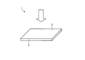
- FIG. 1 is an external view illustrating a Co-based amorphous magnetic ribbon for a magnetic sensor according to an embodiment.
- FIG. 2 is a diagram exemplifying the shape of the Co-based amorphous magnetic ribbon for a magnetic sensor according to the embodiment as seen from the upper surface.
- FIG. 3 is a diagram illustrating a shape of the Co-based amorphous magnetic ribbon for a magnetic sensor according to the embodiment as viewed from the side surface.
- FIG. 4 is an explanatory diagram of the plate thickness according to the embodiment.
- FIG. 5 is a diagram illustrating a magnetic sensor including the Co-based amorphous magnetic ribbon for a magnetic sensor according to the embodiment.
- FIG. 6 is a diagram illustrating a magnetic sensor including the Co-based amorphous magnetic ribbon for a magnetic sensor according to the embodiment.
- FIG. 7 is a diagram illustrating a management system according to the embodiment.
- the Co-based amorphous magnetic ribbon for a magnetic sensor has a width W of 1 mm or less, a length L of 6 mm or more and 100 mm or less, an L/W ratio of 20 or more and 1000 or less, a plate thickness t of 10 ⁇ m or more and 28 ⁇ m or less, and a cross section. Is a rectangular or trapezoidal Co-based amorphous magnetic ribbon.
- 1 to 3 exemplify a Co-based amorphous magnetic ribbon for a magnetic sensor according to the embodiment.
- 1 is an external view
- FIG. 2 is a top view
- FIG. 3 is a side view.
- 1 is a Co-based amorphous magnetic ribbon for a magnetic sensor
- 2 is an upper surface of a Co-based amorphous magnetic ribbon for a magnetic sensor
- 3 is a side surface of a Co-based amorphous magnetic ribbon for a magnetic sensor
- W is a magnetic sensor.
- L is the length of the Co-based amorphous magnetic ribbon for the magnetic sensor
- t is the plate thickness of the Co-based amorphous magnetic ribbon for the magnetic sensor
- ⁇ is the cross section of the Co-based amorphous magnetic ribbon for the magnetic sensor.
- Co-based amorphous is an amorphous alloy containing the largest amount of cobalt (Co) as a constituent element.
- the ribbon of the Co-based amorphous alloy has excellent magnetic properties. Therefore, the magnetic sensor provided with the Co-based amorphous magnetic ribbon for a magnetic sensor has high sensitivity as a magnetic sensor.
- magnetic alloys include Fe-based amorphous alloys and Fe-based fine crystal alloys.
- the Fe-based magnetic alloy contains most Fe (iron) as a constituent element.
- the Co-based amorphous alloy that is a constituent material of the Co-based amorphous magnetic ribbon for the magnetic sensor of the present embodiment has higher corrosion resistance than the Fe-based magnetic alloy.
- the Co-based amorphous alloy is a rust-resistant alloy. Therefore, it is possible to obtain a security paper that is resistant to aging.
- the Co-based amorphous magnetic ribbon for a magnetic sensor may be simply referred to as a magnetic ribbon.
- the magnetic ribbon has a width W of 1 mm or less, a length L of 6 mm or more and 100 mm or less, an L/W ratio of 20 or more and 1000 or less, and a plate thickness t of 10 ⁇ m or more and 28 ⁇ m or less.
- the L/W ratio is the ratio of the width W to the length L of the magnetic ribbon.
- the width W, the length L, and the plate thickness t have a relationship of plate thickness t ⁇ width W ⁇ length L.
- the magnetic ribbon has a polygonal shape when viewed from above.
- the figure illustrates a rectangular shape as viewed from above.
- the short side of the rectangle has a width W and the long side has a length L.
- the arrow direction in FIG. 1 is the direction viewed from above.
- Width W is 1 mm or less. When the width W is larger than 1 mm, it becomes easy to determine the location of the magnetic ribbon when embedded in white paper.
- the lower limit of the width W is preferably 0.05 mm or more. If the width W is less than 0.05 mm (that is, less than 50 ⁇ m), the magnetic ribbon may be broken. Therefore, the width W is preferably 0.05 mm or more and 1 mm or less, more preferably 0.1 mm or more and 0.3 mm or less.
- the length L is 6 mm or more and 100 mm or less. If the length L is less than 6 mm, the receiving sensitivity of the sensor is reduced. If the length exceeds 100 mm, the magnetic ribbon is likely to be twisted. When the magnetic ribbon is twisted, it becomes difficult to maintain the flatness of the paper. Therefore, the length L is preferably 6 mm or more and 100 mm or less, and more preferably 55 mm or less.
- the L/W ratio is 20 or more and 1000 or less. If the L/W ratio is less than 20, the reception sensitivity will decrease. Further, when the L/W ratio exceeds 1000, the length L is too long, so that the magnetic ribbon is likely to be twisted in the step of embedding it in the paper. Therefore, the L/W ratio of the magnetic ribbon is preferably 20 or more and 1000 or less, more preferably 100 or more and 500 or less. Within this range, it is possible to improve reception sensitivity and handleability at the same time.
- the plate thickness t is 10 ⁇ m or more and 28 ⁇ m or less.
- the magnetic ribbon is produced by the roll quenching method. If the plate thickness t is in the range of 10 ⁇ m or more and 28 ⁇ m or less, the thickness of the magnetic ribbon produced by the roll quenching method can be applied as it is. Therefore, mass productivity can be improved.
- the plate thickness t is the thickness of the magnetic ribbon and is the average plate thickness Tv shown in FIG. As shown in FIG. 4, there are irregularities on the surface of the magnetic ribbon.
- FIG. 4 shows an example of a schematic view in which the cross section of the magnetic ribbon is magnified 2000 times by a scanning electron microscope (SEM: Scanning Electron Microscope).
- the plate thickness measured with a micrometer is the maximum value Tm of the thickness of the magnetic ribbon. Therefore, the average plate thickness Tv is calculated by measuring the mass of the constituent material of the magnetic ribbon of unit length/width and calculating from the density of the constituent material.
- the unit length/width referred to here is one magnetic ribbon.
- the unit length/width may be a length/width of two magnetic ribbons or more.
- the ratio (Tm/Tv) between the average plate thickness Tv and the maximum value Tm of FIG. 4 approaches 1, and the larger this ratio is, the surface becomes Indicates that it is rough.
- the W/t ratio which is the ratio of the width W and the plate thickness t, is preferably 3 or more and 20 or less. Further, the W/t ratio is preferably 5 or more and 12 or less.
- Sprinkling the magnetic ribbon onto the paper means at least one of integrating the magnetic ribbon with the paper, kneading the magnetic ribbon into the paper, and sandwiching the magnetic ribbon between the paper. If there are irregularities on the paper surface, problems such as being caught by the pen tip and making holes in the paper or tearing the paper are likely to occur.
- the cross-sectional shape of the magnetic ribbon is rectangular or trapezoidal.
- the rectangular cross-sectional shape means that the angle ⁇ of the four corners is within the range of 90° ⁇ 5° when the cross section perpendicular to the length L direction of the magnetic ribbon is viewed.
- a trapezoidal sectional shape is a structure in which the side surface is an inclined surface. When the cross-sectional shape is trapezoidal, the angle of the inclined surface is preferably 50° or more. If it is less than 50°, the effect of suppressing the overlap between the magnetic ribbons is small.
- a magnified photograph of the magnetic ribbon cross section magnified 200 times with an optical microscope shall be used. Also, the four corner vertices may be slightly rounded.
- the magnetic ribbon of the embodiment preferably satisfies the following general formula.
- M is at least one selected from Ti, V, Cr, Mn, Ni, Cu, Zr, Nb, Mo, Hf, Ta and W.
- a, b, c and x are in the following ranges.
- the unit of the value of x is atomic %.
- Fe can make the magnetostriction constant almost zero by the ratio with Co. Further, the corrosion resistance is improved by using Co as the main component. Therefore, it is possible to obtain a magnetic ribbon that is resistant to deterioration with time and that is resistant to deterioration of magnetic properties.
- the value a in the above general formula is 0.02 or more and 0.10 or less, preferably 0.03 or more and 0.08 or less.
- the magnetic ribbon of the embodiment is a Co-based amorphous alloy ribbon containing the largest amount of Co.
- the values of a, b, c, and x in the above general formula show any of the values within the above range under the condition that most Co is contained.
- the M element is an element that improves soft magnetic properties.
- the M element is Ti (titanium), V (vanadium), Cr (chrome), Mn (manganese), Ni (nickel), Cu (copper), Zr (zirconium), Nb (niobium), Mo (molybdenum), Hf. At least one selected from (hafnium), Ta (tantalum), and W (tungsten). These elements are effective for controlling the Curie temperature. Further, among the M elements, one or more selected from Cr, Zr and Nb are preferable. These elements can improve not only the magnetic properties but also the flexibility of the magnetic ribbon. Further, the b value indicating the content of the M element is 0.20 or less.
- the value of b when the M element is contained is preferably 0.01 or more. If the value of b when the M element is contained is less than 0.01, the effect of containing the element is small. Therefore, when the M element is contained, the value of b is preferably 0.01 or more and 0.20 or less, and more preferably 0.05 or more and 0.15 or less.
- Si (silicon) and B (boron) are essential elements for amorphization.
- the value of x indicating the total content is 10 atom% or more and 40 atom% or less, as described above. If the value of x is less than 10 atomic %, it will be difficult to amorphize. If the value of x exceeds 40 atom %, the Curie temperature becomes too low. Further, it is preferable that both Si (silicon) and B (boron) are contained. When both are contained, the value of c is preferably in the range of 0.2 or more and 0.9 or less. By including both Si and B, it is possible to obtain effects such as lowering iron loss and improving thermal stability.
- the magnetic ribbon does not break even when bent 180°. Bending at 180° means folding the magnetic ribbon in two, like a mountain fold of origami. Since it is not damaged even when folded in half, it is possible to fold the paper provided with the magnetic ribbon. Therefore, the convenience of the paper provided with the magnetic ribbon is improved. In addition, the two folds are mountain folds to the extent that creases are formed. When folding the magnetic ribbon before assembling it into paper, the magnetic ribbon should be folded in the middle of the length L of the magnetic ribbon. Further, when folding the paper provided with the magnetic ribbon, any portion may be folded. In addition, the bending test is performed according to JIS-Z-2248.
- the spring property of the magnetic ribbon can be weakened. If the elasticity is too strong, the magnetic ribbon may fly out of the paper when the paper is folded in half.
- the cross section is a semi-elliptical type like the magnetic alloy fiber of Patent Document 2, the spring property changes depending on the bending direction.
- the semi-elliptical type is sometimes called a kamaboko type. If bent in the direction of increasing springiness, the magnetic alloy fiber may jump out of the paper.
- the magnetic ribbon containing Cr, Nb, and Zr as the M element and controlling the shape, it is possible to achieve both bending property and spring property of the magnetic ribbon.
- the magnetic ribbon may or may not be heat-treated. Magnetic properties are improved by heat treatment.
- the coercive force can be set to about 10 A/m by applying heat treatment.
- the strength decreases. It is easily damaged when bent at 180°. Therefore, when it is desired to maintain the strength, it is preferable not to perform the heat treatment.
- an insulating layer may be provided on the surface of the magnetic ribbon.
- the insulating layer By providing the insulating layer, it is possible to prevent the magnetic ribbon from rusting.
- the insulating layer include an insulating resin film and an oxide film.
- the Co-based amorphous alloy has higher corrosion resistance than the Fe-based amorphous alloy.
- rust will occur after a dozen years.
- the insulating layer is preferably a transparent insulating resin. If it is a transparent resin, even if the magnetic ribbon is sprinkled on the white paper, no problem occurs in the hue.
- the magnetic ribbon as described above can be applied to a magnetic sensor equipped with the magnetic ribbon.
- a magnetic sensor is an object equipped with a magnetic ribbon.
- Objects provided with magnetic ribbons include, but are not limited to, paper, tags, pens, and the like.
- a case where the magnetic sensor is paper will be described as an example.
- the paper provided with the magnetic ribbon may be referred to as security paper.
- FIG. 5 shows an example of the paper according to the embodiment.
- 1 is a magnetic ribbon
- 4 is a paper body
- 5 is a paper provided with a magnetic ribbon.
- Paper provided with a magnetic ribbon may be referred to as security paper.
- Security paper is paper that requires crime prevention management such as theft prevention, forgery prevention, and number management.
- Examples of security papers include securities, contracts, and copies of confidential information.
- the magnetic ribbon may be attached to the surface of the paper body, or may be embedded in the paper body.
- the embedding inside the paper body means that a magnetic ribbon is sandwiched between two paper bodies to form one sheet of paper. Since the magnetic ribbon according to the embodiment controls the size and shape of the magnetic ribbon, it is difficult for the magnetic ribbons to overlap each other when the magnetic ribbon is embedded in the paper body. Therefore, the flatness of the paper can be maintained. In addition, since it is possible to prevent the magnetic ribbons from overlapping each other, it is difficult to specify the position of the magnetic ribbons even when applied to white paper. From this point as well, the crime prevention effect is enhanced.
- the number of magnetic ribbons used for security paper should be one or more. The following numbers are preferable in order to improve the sensor function.
- the magnetic sensor which is a paper, preferably has three or more and 2500 or less magnetic ribbons per paper area (A4) 62370 mm 2 .
- the size is based on A4 size.
- the preferred number should be changed by the area ratio.
- a plurality of Co-based amorphous magnetic ribbons for a magnetic sensor at random by providing a plurality of them.
- the random arrangement makes it difficult to specify where the Co-based amorphous magnetic ribbon for a magnetic sensor is buried. Thereby, the crime prevention effect can be enhanced.
- Random arrangement means a state in which magnetic ribbons are distributed evenly over the entire paper.
- the state in which the magnetic ribbons are evenly distributed over the entire paper means the content or the number of magnetic ribbons contained in each area when the paper is divided into a plurality of areas of a predetermined size and range. Mean that they are substantially the same. Substantially the same means that they are the same within a range of ⁇ 10%. For example, in the case of A4 size paper, it is preferable that the number of magnetic ribbons is substantially the same when divided into four equal parts.
- magnetic thin ribbons are arrayed and distributed at specific fixed positions on the paper, the specific positions can be separated and taken out at once. For example, assume a case where the magnetic ribbon is arranged only in all the right corner regions of each of the five sheets of paper. In this case, the right corner area of this paper is cut off, so that the paper does not have a magnetic ribbon, and the security is deteriorated. If the magnetic ribbons are randomly arranged on the entire paper, it is possible to prevent the security from being deteriorated due to such cutting and improve the security performance such as theft prevention.
- the plurality of magnetic ribbons distributed on the paper are arranged such that at least a part of the plurality of magnetic ribbons have directions of lengths L different from each other. Further, it is more preferable to radially arrange a plurality of magnetic ribbons on the paper. As shown in FIG. 6, the radial shape means that at least a part of the plurality of magnetic ribbons are arranged such that the length L directions thereof are different from each other, and the plurality of magnetic ribbons are arranged at specific positions on the paper.
- the center means a shape that is arranged so as to spread in all directions from the center. The center may or may not coincide with the center position of the paper.
- intersection of the extended straight lines that extend in the lengthwise direction a plurality of magnetic ribbons forming a radial shape is not limited to one point, and may be a plurality of points. That is, the center of the radial shape formed by the plurality of magnetic ribbons is not limited to the shape concentrated at one point. Further, a plurality of groups of magnetic ribbons arranged radially may be arranged on one sheet of paper.
- the receiving sensitivity of the paper magnetic sensor by the management system described later will be improved. This is because it is easy to receive radio waves from any direction.
- the number of magnetic ribbons contained in the paper is preferably 50 or less per paper area (A4) 62370 mm 2 .
- the receiving sensitivity is improved. Therefore, when the length L of the magnetic ribbon is 25 mm or more, the number of magnetic ribbons contained in the paper is 3 or more and 50 or less, and further 3 or more and 20 or less per paper area (A4) 62370 mm 2. The following is preferable.
- the plurality of magnetic ribbons be radially arranged.
- the number of magnetic ribbons contained in the paper preferably exceeds 50 per paper area (A4) 62370 mm 2 .
- both length L of the magnetic ribbon of 25 mm or more and less than 25 mm may be used. Further, when the number of long ones (length L is 25 mm or more) is three or more, it is preferable to arrange them radially as described above.
- the paper used for the security paper is one type selected from plain paper, high-quality paper, and recycled paper.
- Plain paper is a general term for paper used for copy paper and printer paper. Plain paper is also called PPC paper (Plain Paper Copier). It is distinguished from thermal paper. It is suitable for crime prevention management when printing confidential information on plain paper.
- the high-quality paper indicates that manufactured with 100% chemical pulp.
- recycled paper refers to one manufactured from a mixture of chemical pulp and recycled pulp.
- White paper indicates a paper having a whiteness of 70% or more.
- the whiteness is measured according to JIS-P-8148.
- the measurement of whiteness is a method (ISO whiteness R 457 ) of quantifying the amount of reflected light when light is applied to the surface of paper.
- the whiteness of recycled paper is 65% or more and 75% or less.
- plain paper and high-quality paper account for 80% or more. Since the magnetic ribbon according to the embodiment can prevent overlapping in the paper, it is possible to suppress a decrease in the whiteness of the paper.
- the paper according to the embodiment can maintain the whiteness of 70% or more even when the magnetic ribbon is embedded. This is the level at which the position of the magnetic ribbon cannot be specified unless it is observed by passing sunlight through the paper. Therefore, the position of the magnetic ribbon cannot be specified by general indoor illumination light. Therefore, the crime prevention effect can be enhanced. Further, it is most preferable to use it on white plain paper.
- the paper with the magnetic ribbon as described above is suitable for various management systems.
- the management system preferably includes a gate unit that performs transmission and reception.
- FIG. 7 illustrates the management system according to the embodiment.
- 5 is a security paper which is a paper provided with a magnetic ribbon
- 6 is a management system
- 7 is a gate unit for transmitting
- 8 is a gate unit for receiving.
- the management system 6 has a pair of gates that transmit and receive radio waves. Specifically, the management system 6 has a gate unit 7 that transmits radio waves and a gate unit 8 that receives radio waves. Radio waves are transmitted from the gate unit 7, and the radio waves are received by the gate unit 8. When the security paper 5 passes between the gate unit 7 and the gate unit 8, the received signal of the radio wave received by the gate unit 8 changes. As a result, it can be seen that the security paper 5 has passed the gate portion.
- the gate section 7 is provided with an exciting coil. Further, the gate portion 8 is provided with a detection coil.
- the exciting coil and the detecting coil are arranged so as to face each other with the security paper passing between the gate portion 7 and the gate portion 8 interposed therebetween. It is assumed that the security paper 5 passes between the gate portion 7 and the gate portion 8 by applying an alternating excitation magnetic field having a predetermined strength to the excitation coil.
- the detection coil of the gate unit 8 for example, extremely steep magnetization reversal occurs. By detecting the change in the received signal of the radio wave due to the magnetization reversal, it is possible to detect that the security paper 5 has passed through the gate portion.
- the effect of theft prevention can be obtained.
- the anti-theft effect can also be obtained by installing the management system 6 in a safe or a confidential document storage shelf. Further, when the management system 6 is applied to a multi-function peripheral or the like, it is also effective for managing the number of security papers. It is also effective for managing illegal copies.
- the gate unit 8 may be referred to as a theft prevention gate unit because the antitheft effect can be obtained.
- radio waves having a frequency of 1 kHz or more and 200 kHz or less are used.
- the magnetic ribbon according to the embodiment has excellent reception sensitivity at 1 kHz or more and 200 kHz or less. Therefore, the receiving sensitivity can be improved even if the number of magnetic ribbons is small.
- the frequency of the radio wave used in the management system according to the embodiment may be a frequency outside the range of 1 kHz to 200 kHz.
- the method for producing the magnetic ribbon according to the embodiment is not particularly limited as long as it has the above-mentioned configuration, but the following method can be mentioned as a method for obtaining it with high yield.
- the process of manufacturing a long magnetic ribbon using the roll quenching method is performed.
- a known method can be applied to the roll quenching method.
- a molten alloy to be a mother alloy of a Co-based amorphous alloy is prepared.
- the molten alloy preferably satisfies the above general formula.
- a long magnetic ribbon By supplying the molten alloy from the injection nozzle onto a cooling roll that rotates at high speed, a long magnetic ribbon can be produced.
- the shape of the injection nozzle rectangular the cross-sectional shape can be made rectangular.
- the plate thickness t can be adjusted. It is preferable to set the plate thickness of the long magnetic ribbon as the plate thickness t of the magnetic ribbon.
- the process of cutting the long magnetic ribbon and adjusting the length L and width W of the magnetic ribbon shall be performed.
- the cutting step it is preferable to cut in a direction in which the width direction of the long magnetic ribbon becomes the length L of the magnetic ribbon. Further, it is preferable that the width of the long magnetic ribbon and the length L of the magnetic ribbon are the same. With such a shape, the width of the long magnetic ribbon and the length L of the magnetic ribbon can be made the same by adjusting the long side of the injection nozzle to the length L of the magnetic ribbon.
- an insulating layer should be provided on the surface of the magnetic ribbon if necessary.
- the insulating layer is an oxide layer or a resin layer.
- Examples of the method of providing the magnetic ribbon include a method of sticking to the surface of paper and a method of embedding inside the paper.
- the magnetic ribbon according to the embodiment has a rectangular cross section. For this reason, it is difficult for the magnetic ribbons to overlap each other when placed on paper. Further, since the magnetic ribbon of the present embodiment has the predetermined length L, width W and plate thickness t, the tint of the paper need not be changed. For example, white paper having a whiteness of 70% or more can be obtained. Further, the number of magnetic ribbons provided on the paper is preferably as described above.
- Example 1 to Example 10 and Comparative Example 3 are obtained by cutting a long magnetic ribbon produced by the roll quenching method. Further, in Examples 1 to 6 and 9 to 10, the long magnetic ribbons were cut so that the width direction of each of the magnetic ribbons and the comparative magnetic ribbon was the length L. It is a thing.
- Example 8 is a magnetic ribbon obtained by heat-treating the magnetic ribbon of Example 1. The heat treatment was carried out at a temperature about 100° C. lower than the crystallization temperature of the magnetic ribbon for 1 hour.
- the magnetic ribbons of Examples 1 to 4 and 6 to 10 and the comparative magnetic ribbons of Comparative Examples 2 and 4 each had a rectangular cross section.
- the angles of the rectangular cross-sections were within the range of 90° ⁇ 5°.
- the angle of the trapezoid which is the cross-sectional shape of the magnetic ribbon of Example 5, was 60° or more.
- the comparative magnetic ribbon of Comparative Example 1 is a Fe-based amorphous alloy wire with a diameter of 30 ⁇ m.
- the cross-sectional shape of the comparative magnetic ribbon of Comparative Example 1 was circular.
- the cross-sectional shape of the comparative magnetic ribbon of Comparative Example 3 was a semi-elliptical shape as shown in FIG.
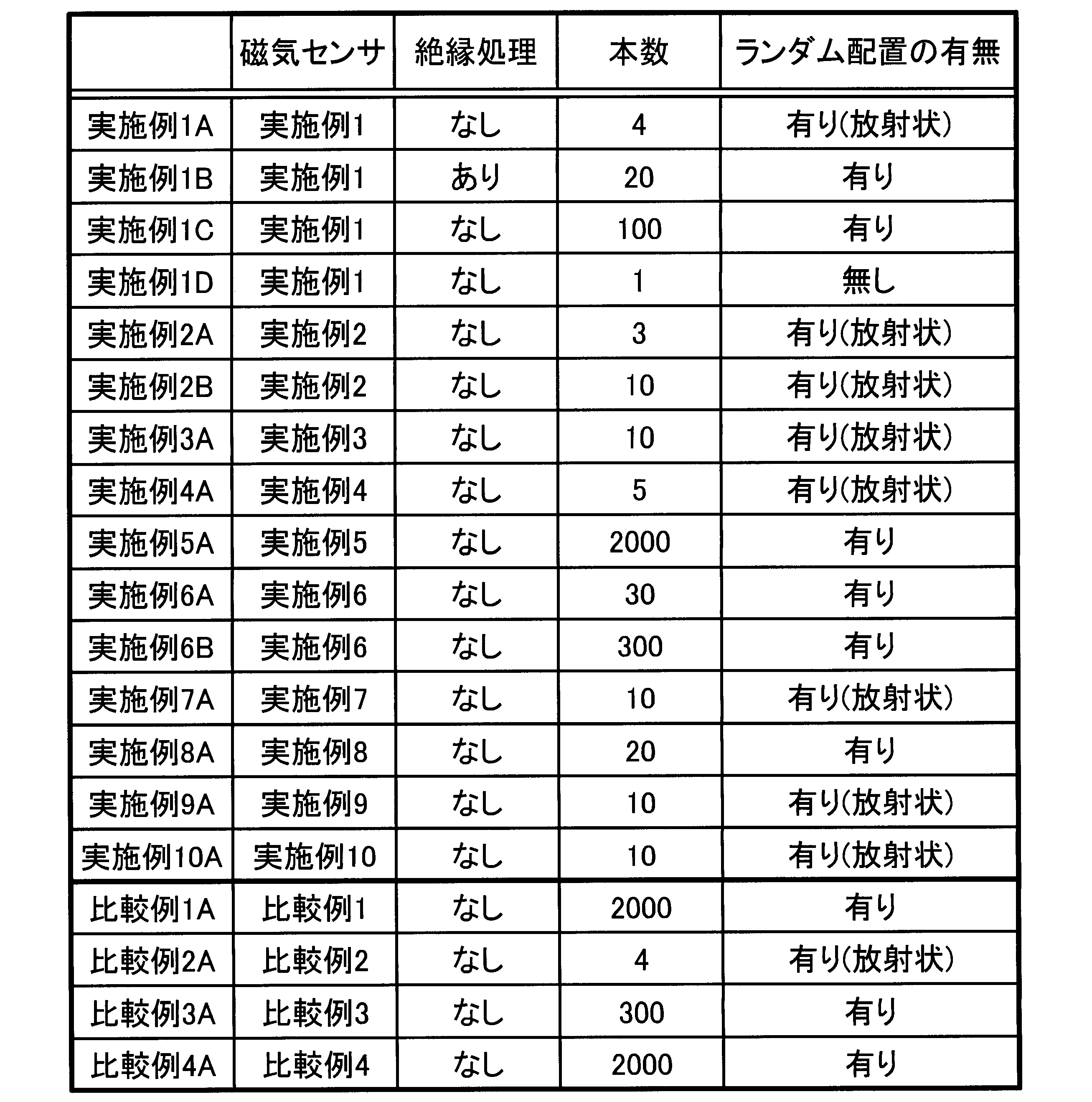
- Examples 1A to 10A security papers which are papers provided with the magnetic ribbon according to Examples 1 to 10 were produced. Further, as Comparative Examples 1A to 4A, comparative security papers, which are comparative papers provided with the comparative magnetic ribbon according to Comparative Examples 1 to 4, were produced.
- A4 width 297 mm x width 210 mm
- a magnetic ribbon was placed on a piece of paper. Another sheet of paper was stuck together to form one sheet of paper (A4 size). The number of magnetic ribbons is as shown in Table 2.
- a security paper was produced by this process.
- a comparative security paper was produced by arranging a comparative magnetic ribbon on these two sheets of paper.
- an insulating layer made of parylene resin was provided if necessary.
- the number is the number per A4 size.
- the paper (paper body 4) used had a whiteness of 85%.
- 20 or more were randomly arranged, and those less than 20 were arranged radially or similar to the center of the paper.
- the presence/absence of random arrangement means “existence” means that at least a part of the plurality of magnetic ribbons or the plurality of comparative magnetic ribbons arranged on the paper is the length L direction of the magnetic ribbon or the comparative magnetic ribbon. Means that they are arranged differently from each other. Also, the presence/absence of random arrangement “Yes (radial)” means that at least a part of the plurality of magnetic ribbons or the plurality of comparative magnetic ribbons provided on the paper is radially arranged. To do.
- the whiteness was measured according to JIS-P-8148. Specifically, it was performed by a method (ISO whiteness R 457 ) of quantifying the amount of reflected light when light is applied to the surface of the security paper.
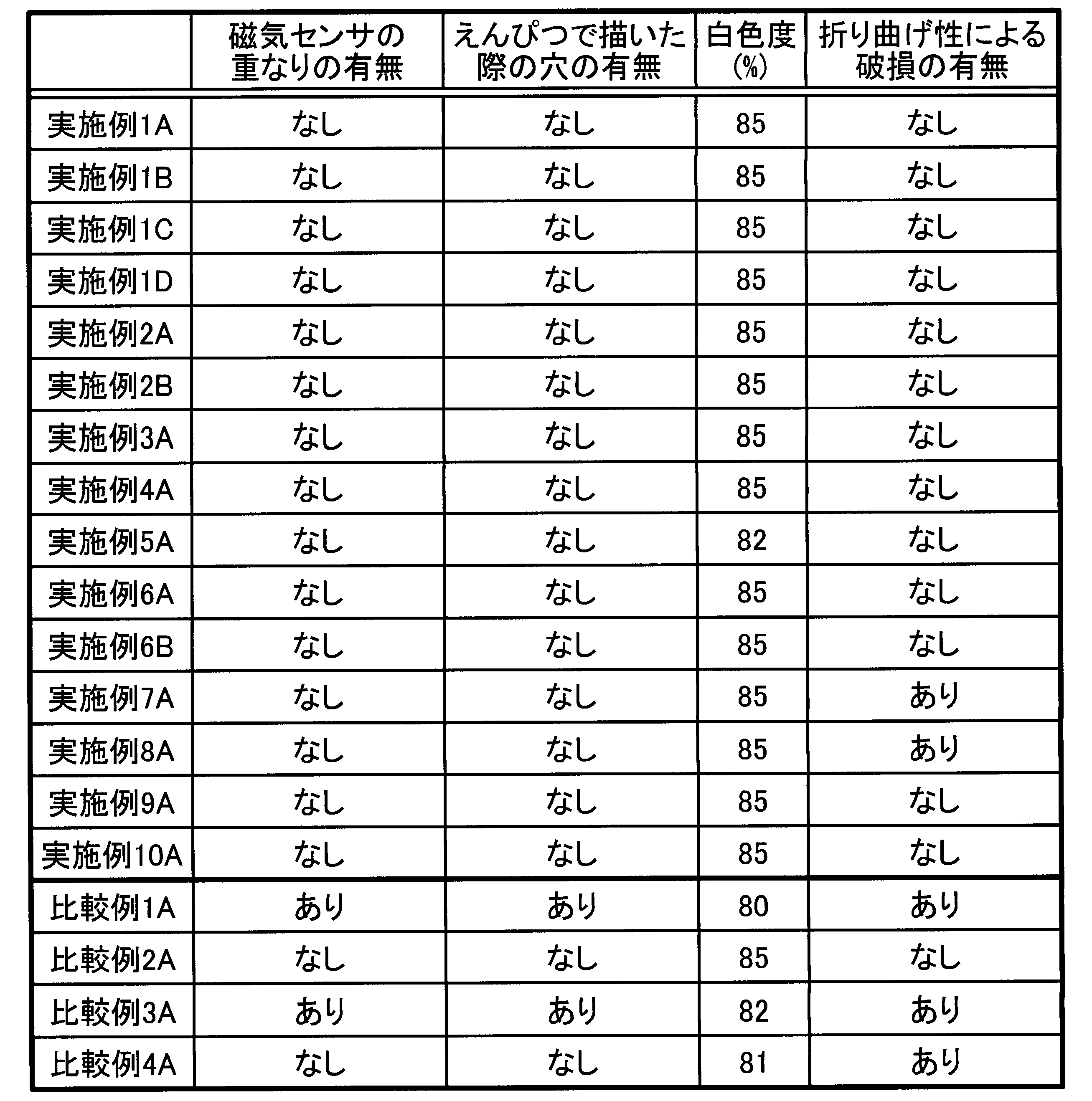
- Foldability was examined by checking whether the magnetic ribbon or the security paper was damaged when the paper was folded at 180° in the place where the magnetic ribbon was present.
- the 180° bending was performed by bending 180° in one direction and then 180° on the opposite side. Thereby, the presence or absence of damage was examined.
- the breakage means a state in which at least a part is cracked or a state in which at least a part is cut.
- the security papers of Examples 1A to 10A had no overlapping of magnetic ribbons. For this reason, even when drawn with a pencil, there was no problem such as a hole in the paper.
- Comparative Example 1A having the comparative magnetic ribbon of Comparative Example 1 having a circular cross section and Comparative Example 3A having the comparative magnetic ribbon of Comparative Example 3 having a semi-elliptical shape The comparative magnetic ribbons were overlapped. The flatness is impaired where the comparative magnetic ribbons overlap. Therefore, in the comparative security papers of Comparative Example 1A and Comparative Example 3A, holes were made in the paper when the pencil writing was performed.
- the security paper of the example in which the number of magnetic ribbons is 50 or less maintained the whiteness of 85%. In other words, the whiteness of the original paper was maintained as it was. Further, among Examples 1A to 10A, those in which the number of magnetic ribbons exceeded 50 included those in which the whiteness was decreased.
- the coercive force (A/m) was measured at 10 kHz and an applied magnetic field of 80 A/m.
- the receiving sensitivity was measured using the management system 6 shown in FIG.
- the management system 6 includes the gate unit 7 that performs transmission and the gate unit 8 that receives.
- the size of the gate unit 7 on the transmitting side and the size of the gate unit 8 on the receiving side were the same, and the width W 326 mm x depth D 80 mm x height H 1670 mm was used.
- the distance between the gate portion 7 and the gate portion 8 was set to 1.5 m.
- the operation signal which is an alternating magnetic field applied to the exciting coil of the gate section 7 on the transmitting side, has a sine wave of 1.04 kHz.
- the receiving sensitivity was measured when the security paper and the comparative security paper were passed between the gate section 7 and the gate section 8.
- the reception sensitivity is shown as a relative numerical value when the magnitude of the reception signal when the comparative security paper of Comparative Example 1A is used is 1. The larger the numerical value of the reception sensitivity, the larger the signal obtained.
- a sine wave signal is obtained on the receiving side with respect to the signal on the exciting side, a pulse current is generated when the magnetic material passes through during this time. The peak value of this pulse current was read.
- the coercive force of the security papers of Examples 1A to 10A using the magnetic ribbon of the above embodiment was low. It means that the lower the coercive force is, the sooner it returns to the unmagnetized state. That is, the sensor can be turned on and off quickly.
- the security papers of Examples 1A to 10A had higher reception sensitivity than the comparative security papers of Comparative Examples 1A to 4A. Further, from the comparison between Example 1A, Example 1B, and Example 1C, it is understood that if the length L of the magnetic ribbon is 25 mm or more, the number of magnetic ribbons to be provided is 50 or less. Further, when the number of magnetic ribbons was one as in Example 1D, the receiving sensitivity was lower than that in Examples 1A to 1C.
- Example 8A had higher reception sensitivity than the other Examples and Comparative Examples 1A to 4A. Heat treatment is effective for improving magnetic properties. For this reason, it is preferable to adjust the presence or absence of heat treatment depending on whether or not the security paper is bendable.
- Comparative Example 1A and Comparative Example 2A when the comparative magnetic ribbon which is the Fe-based amorphous alloy was used, the receiving sensitivity was lower than when the Co-based amorphous alloy was used. Further, even if a Co-based amorphous alloy is used as in Comparative Example 3A and Comparative Example 4A, the size of the comparative magnetic ribbon is different from that of the magnetic ribbon, so that the receiving sensitivity is lowered.
- the security paper which is the paper including the magnetic ribbons according to the embodiment, can suppress the overlapping of the magnetic ribbons. Further, since the whiteness can be maintained, it is not necessary to change the original color of the paper. In addition, since the bending property was also good, the handling property was good. Also, the receiving sensitivity was excellent. Therefore, the reliability of the management system is also improved.
- Magnetic ribbon (Co-based amorphous magnetic ribbon for magnetic sensor) 2... Top surface of magnetic ribbon 3... Side surface of magnetic ribbon 5... Paper (magnetic sensor, security paper) 6... Management system 7... Sending gate 8... Receiving gate W... Magnetic ribbon width L... Magnetic ribbon length t... Magnetic ribbon thickness ⁇ ... Four magnetic ribbon cross sections Angle of the corner
Landscapes
- Physics & Mathematics (AREA)
- Engineering & Computer Science (AREA)
- Power Engineering (AREA)
- General Physics & Mathematics (AREA)
- Electromagnetism (AREA)
- Chemical & Material Sciences (AREA)
- Dispersion Chemistry (AREA)
- Condensed Matter Physics & Semiconductors (AREA)
- Soft Magnetic Materials (AREA)
- Measuring Magnetic Variables (AREA)
- Laminated Bodies (AREA)
- Manufacturing Of Magnetic Record Carriers (AREA)
Abstract
Description
0≦b≦0.20
0.2≦c≦1.0
10≦x≦40
(実施例1~実施例10、比較例1~比較例4)
実施例および比較例として、表1に示す磁性薄帯および比較磁性薄帯を用意した。


2…磁性薄帯の上面
3…磁性薄帯の側面
5…紙(磁気センサ,セキュリティペーパー)
6…管理システム
7…送信を行うゲート部
8…受信を行うゲート部
W…磁性薄帯の幅
L…磁性薄帯の長さ
t…磁性薄帯の板厚
θ…磁性薄帯断面の4つ角の角度
Claims (12)
- 幅Wが1mm以下、長さLが6mm以上100mm以下、L/W比が20以上1000以下、板厚tが10μm以上28μm以下、断面が長方形または台形であるCo系アモルファス磁性薄帯からなる、磁気センサ用Co系アモルファス磁性薄帯。
- W/t比が3以上20以下である、請求項1に記載の磁気センサ用Co系アモルファス磁性薄帯。
- 180°に折り曲げても破損しない、請求項1に記載の磁気センサ用Co系アモルファス磁性薄帯。
- Co系アモルファス磁性薄帯表面に絶縁層を設けた、請求項1に記載の磁気センサ用Co系アモルファス磁性薄帯。
- 請求項1に記載の磁気センサ用Co系アモルファス磁性薄帯を具備してなる、磁気センサ。
- 前記磁気センサは紙である、請求項5に記載の磁気センサ。
- 紙面積(A4)62370mm2あたり、前記磁気センサ用Co系アモルファス磁性薄帯を3本以上2500本以下、具備している、請求項6に記載の磁気センサ。
- 前記磁気センサ用Co系アモルファス磁性薄帯同士が重なっていない、請求項5に記載の磁気センサ。
- 前記磁気センサ用Co系アモルファス磁性薄帯の長さLが25mm以上であるとき、紙面積(A4)62370mm2あたりの前記磁気センサ用Co系アモルファス磁性薄帯が50本以下である、請求項6に記載の磁気センサ。
- 前記磁気センサ用Co系アモルファス磁性薄帯の長さLが25mm未満であるとき、紙面積(A4)62370mm2あたりの前記磁気センサ用Co系アモルファス磁性薄帯が50本を越えている、請求項6に記載の磁気センサ。
- 請求項5に記載の磁気センサが搭載された、管理システム。
- 電波の送受信を行う一対のゲート部を具備してなる、請求項11に記載の管理システム。
Priority Applications (7)
| Application Number | Priority Date | Filing Date | Title |
|---|---|---|---|
| KR1020217015755A KR20210083296A (ko) | 2018-11-29 | 2019-11-21 | 자기 센서용 Co계 아몰퍼스 자성 박대 및 그것을 사용한 자기 센서 그리고 관리 시스템 |
| JP2020557623A JP7577541B2 (ja) | 2018-11-29 | 2019-11-21 | セキュリティペーパー用Co系アモルファス磁性薄帯およびそれを用いた磁気センサ並びに管理システム |
| CN201980078045.1A CN113168946A (zh) | 2018-11-29 | 2019-11-21 | 磁传感器用Co系非晶磁性薄带及使用其的磁传感器及管理系统 |
| KR1020237035171A KR20230150398A (ko) | 2018-11-29 | 2019-11-21 | 자기 센서용 Co계 아몰퍼스 자성 박대, 시큐리티 페이퍼용 자기 센서 및 관리 시스템 |
| KR1020237010655A KR102601878B1 (ko) | 2018-11-29 | 2019-11-21 | 자기 센서용 Co계 아몰퍼스 자성 박대, 시큐리티 페이퍼용 자기 센서 및 관리 시스템 |
| US17/328,139 US20210287833A1 (en) | 2018-11-29 | 2021-05-24 | Co-based amorphous magnetic thin strip for magnetic sensor, magnetic sensor using the same, and management system |
| JP2024001943A JP2024036356A (ja) | 2018-11-29 | 2024-01-10 | セキュリティペーパー、およびセキュリティペーパーの製造方法 |
Applications Claiming Priority (2)
| Application Number | Priority Date | Filing Date | Title |
|---|---|---|---|
| JP2018223335 | 2018-11-29 | ||
| JP2018-223335 | 2018-11-29 |
Related Child Applications (1)
| Application Number | Title | Priority Date | Filing Date |
|---|---|---|---|
| US17/328,139 Continuation US20210287833A1 (en) | 2018-11-29 | 2021-05-24 | Co-based amorphous magnetic thin strip for magnetic sensor, magnetic sensor using the same, and management system |
Publications (1)
| Publication Number | Publication Date |
|---|---|
| WO2020110899A1 true WO2020110899A1 (ja) | 2020-06-04 |
Family
ID=70852988
Family Applications (1)
| Application Number | Title | Priority Date | Filing Date |
|---|---|---|---|
| PCT/JP2019/045608 Ceased WO2020110899A1 (ja) | 2018-11-29 | 2019-11-21 | 磁気センサ用Co系アモルファス磁性薄帯およびそれを用いた磁気センサ並びに管理システム |
Country Status (5)
| Country | Link |
|---|---|
| US (1) | US20210287833A1 (ja) |
| JP (2) | JP7577541B2 (ja) |
| KR (3) | KR20230150398A (ja) |
| CN (1) | CN113168946A (ja) |
| WO (1) | WO2020110899A1 (ja) |
Cited By (2)
| Publication number | Priority date | Publication date | Assignee | Title |
|---|---|---|---|---|
| JP2022054924A (ja) * | 2020-09-28 | 2022-04-07 | セイコーエプソン株式会社 | 磁性体シートおよびその製造方法 |
| JP2024036356A (ja) * | 2018-11-29 | 2024-03-15 | 株式会社東芝 | セキュリティペーパー、およびセキュリティペーパーの製造方法 |
Citations (4)
| Publication number | Priority date | Publication date | Assignee | Title |
|---|---|---|---|---|
| JP2000099937A (ja) * | 1998-09-21 | 2000-04-07 | Toshiba Corp | 情報記録媒体 |
| JP2008020579A (ja) * | 2006-07-12 | 2008-01-31 | Fuji Xerox Co Ltd | 磁性体ワイヤー及び記録媒体 |
| JP2009151687A (ja) * | 2007-12-21 | 2009-07-09 | Fuji Xerox Co Ltd | 検知装置および処理システム |
| JP2014161119A (ja) * | 2008-12-22 | 2014-09-04 | Toshiba Corp | 検知システム |
Family Cites Families (12)
| Publication number | Priority date | Publication date | Assignee | Title |
|---|---|---|---|---|
| JPH07266768A (ja) * | 1994-03-31 | 1995-10-17 | Toppan Printing Co Ltd | セキュリティ磁気データ付き透かし用紙 |
| JP3407611B2 (ja) * | 1997-07-14 | 2003-05-19 | 日新電機株式会社 | リアクトル用ブロック鉄心 |
| JP2000119825A (ja) * | 1998-10-15 | 2000-04-25 | Hitachi Metals Ltd | Fe基アモルファス合金薄帯およびそれを用いたFe基ナノ結晶軟磁性合金薄帯ならびに磁心 |
| WO2000045400A1 (en) * | 1999-01-26 | 2000-08-03 | Hitachi Metals, Ltd. | Diskette type memory card adapter, magnetic sensor therefor magnetic core, method for manufacturing the magnetic core |
| JP4128721B2 (ja) * | 2000-03-17 | 2008-07-30 | 株式会社東芝 | 情報記録物品 |
| JP2002190416A (ja) * | 2000-12-22 | 2002-07-05 | Toshiba Corp | インダクタンス素子およびそれを用いたスナバー回路 |
| US20070072005A1 (en) * | 2003-09-11 | 2007-03-29 | Tdk Corporation | Magnetic thin film for high frequency, method of manufacturing the same, and magnetic device |
| JP4529420B2 (ja) | 2003-11-18 | 2010-08-25 | 富士ゼロックス株式会社 | セキュリティペーパーとその製造方法および装置 |
| JP4807065B2 (ja) * | 2005-12-22 | 2011-11-02 | 富士ゼロックス株式会社 | 記録媒体、及びその製造方法 |
| JP6300075B2 (ja) * | 2014-01-27 | 2018-03-28 | 日立金属株式会社 | コイル部品 |
| JP6596923B2 (ja) * | 2015-05-22 | 2019-10-30 | 富士ゼロックス株式会社 | 記録用紙、及び記録用紙の製造方法 |
| KR20230150398A (ko) * | 2018-11-29 | 2023-10-30 | 가부시끼가이샤 도시바 | 자기 센서용 Co계 아몰퍼스 자성 박대, 시큐리티 페이퍼용 자기 센서 및 관리 시스템 |
-
2019
- 2019-11-21 KR KR1020237035171A patent/KR20230150398A/ko not_active Ceased
- 2019-11-21 WO PCT/JP2019/045608 patent/WO2020110899A1/ja not_active Ceased
- 2019-11-21 JP JP2020557623A patent/JP7577541B2/ja active Active
- 2019-11-21 KR KR1020217015755A patent/KR20210083296A/ko not_active Ceased
- 2019-11-21 CN CN201980078045.1A patent/CN113168946A/zh active Pending
- 2019-11-21 KR KR1020237010655A patent/KR102601878B1/ko active Active
-
2021
- 2021-05-24 US US17/328,139 patent/US20210287833A1/en not_active Abandoned
-
2024
- 2024-01-10 JP JP2024001943A patent/JP2024036356A/ja active Pending
Patent Citations (4)
| Publication number | Priority date | Publication date | Assignee | Title |
|---|---|---|---|---|
| JP2000099937A (ja) * | 1998-09-21 | 2000-04-07 | Toshiba Corp | 情報記録媒体 |
| JP2008020579A (ja) * | 2006-07-12 | 2008-01-31 | Fuji Xerox Co Ltd | 磁性体ワイヤー及び記録媒体 |
| JP2009151687A (ja) * | 2007-12-21 | 2009-07-09 | Fuji Xerox Co Ltd | 検知装置および処理システム |
| JP2014161119A (ja) * | 2008-12-22 | 2014-09-04 | Toshiba Corp | 検知システム |
Cited By (3)
| Publication number | Priority date | Publication date | Assignee | Title |
|---|---|---|---|---|
| JP2024036356A (ja) * | 2018-11-29 | 2024-03-15 | 株式会社東芝 | セキュリティペーパー、およびセキュリティペーパーの製造方法 |
| JP2022054924A (ja) * | 2020-09-28 | 2022-04-07 | セイコーエプソン株式会社 | 磁性体シートおよびその製造方法 |
| JP7501282B2 (ja) | 2020-09-28 | 2024-06-18 | セイコーエプソン株式会社 | 磁性体シートおよびその製造方法 |
Also Published As
| Publication number | Publication date |
|---|---|
| KR20230150398A (ko) | 2023-10-30 |
| KR102601878B1 (ko) | 2023-11-14 |
| JP7577541B2 (ja) | 2024-11-05 |
| US20210287833A1 (en) | 2021-09-16 |
| KR20230048167A (ko) | 2023-04-10 |
| KR20210083296A (ko) | 2021-07-06 |
| JPWO2020110899A1 (ja) | 2021-12-23 |
| JP2024036356A (ja) | 2024-03-15 |
| CN113168946A (zh) | 2021-07-23 |
Similar Documents
| Publication | Publication Date | Title |
|---|---|---|
| JP2024036356A (ja) | セキュリティペーパー、およびセキュリティペーパーの製造方法 | |
| EP3286758B1 (en) | Recording medium | |
| CN108564754B (zh) | 一种声磁防盗标签及其偏置片 | |
| JP4128721B2 (ja) | 情報記録物品 | |
| KR102297428B1 (ko) | 보안용지, 보안매체 및 보안용지 제조방법 | |
| KR20170005728A (ko) | 보안용지 | |
| EP2184726A1 (en) | Label Sheet | |
| JP5216536B2 (ja) | 静止機器用鉄心 | |
| JP4525242B2 (ja) | 磁性体が付与された媒体および磁性体検知装置 | |
| KR101956710B1 (ko) | 보안 용지 인식 장치 및 방법, 보안 용지 | |
| JP7695547B2 (ja) | 巻鉄心及び巻鉄心の製造方法 | |
| WO2024024958A1 (ja) | シート状磁性部材 | |
| KR102497168B1 (ko) | 출력물 유출 방지용 기록매체 | |
| US20230402220A1 (en) | Wound core | |
| KR20200130001A (ko) | 보안용 기록매체 및 그 제조방법 | |
| JP7695546B2 (ja) | 巻鉄心 | |
| JP7648871B2 (ja) | 巻鉄心 | |
| US12194771B2 (en) | Dual-color shift security film | |
| JP2001032192A (ja) | 偽造防止用スレッドとそれを用いた偽造防止用紙 | |
| JP2000099937A (ja) | 情報記録媒体 | |
| JPH08324168A (ja) | 商品券 | |
| KR20170041455A (ko) | 정보 유출 방지를 위한 보안기재 및 이의 제조방법 |
Legal Events
| Date | Code | Title | Description |
|---|---|---|---|
| 121 | Ep: the epo has been informed by wipo that ep was designated in this application |
Ref document number: 19889798 Country of ref document: EP Kind code of ref document: A1 |
|
| ENP | Entry into the national phase |
Ref document number: 2020557623 Country of ref document: JP Kind code of ref document: A |
|
| ENP | Entry into the national phase |
Ref document number: 20217015755 Country of ref document: KR Kind code of ref document: A |
|
| NENP | Non-entry into the national phase |
Ref country code: DE |
|
| 122 | Ep: pct application non-entry in european phase |
Ref document number: 19889798 Country of ref document: EP Kind code of ref document: A1 |