EP3286758B1 - Recording medium - Google Patents
Recording medium Download PDFInfo
- Publication number
- EP3286758B1 EP3286758B1 EP16725942.3A EP16725942A EP3286758B1 EP 3286758 B1 EP3286758 B1 EP 3286758B1 EP 16725942 A EP16725942 A EP 16725942A EP 3286758 B1 EP3286758 B1 EP 3286758B1
- Authority
- EP
- European Patent Office
- Prior art keywords
- microwires
- recording medium
- paper
- layer
- metal core
- Prior art date
- Legal status (The legal status is an assumption and is not a legal conclusion. Google has not performed a legal analysis and makes no representation as to the accuracy of the status listed.)
- Active
Links
- 239000010410 layer Substances 0.000 claims description 55
- 239000002184 metal Substances 0.000 claims description 39
- 229910052751 metal Inorganic materials 0.000 claims description 39
- 238000000576 coating method Methods 0.000 claims description 32
- 239000011248 coating agent Substances 0.000 claims description 31
- 239000011521 glass Substances 0.000 claims description 30
- 238000004519 manufacturing process Methods 0.000 claims description 22
- 238000000034 method Methods 0.000 claims description 21
- 239000000463 material Substances 0.000 claims description 19
- 239000000835 fiber Substances 0.000 claims description 16
- 238000007639 printing Methods 0.000 claims description 16
- XLYOFNOQVPJJNP-UHFFFAOYSA-N water Substances O XLYOFNOQVPJJNP-UHFFFAOYSA-N 0.000 claims description 16
- 239000002356 single layer Substances 0.000 claims description 14
- 239000000203 mixture Substances 0.000 claims description 13
- 229910000599 Cr alloy Inorganic materials 0.000 claims description 7
- 229910052742 iron Inorganic materials 0.000 claims description 7
- 229910052804 chromium Inorganic materials 0.000 claims description 6
- 239000011247 coating layer Substances 0.000 claims description 5
- 230000009467 reduction Effects 0.000 claims description 4
- 238000011282 treatment Methods 0.000 claims description 4
- 238000009827 uniform distribution Methods 0.000 claims description 4
- 229910000808 amorphous metal alloy Inorganic materials 0.000 claims description 3
- 238000001514 detection method Methods 0.000 description 36
- 238000012360 testing method Methods 0.000 description 22
- 238000009826 distribution Methods 0.000 description 13
- 230000007423 decrease Effects 0.000 description 9
- 239000006185 dispersion Substances 0.000 description 7
- 230000008569 process Effects 0.000 description 7
- XEEYBQQBJWHFJM-UHFFFAOYSA-N iron Substances [Fe] XEEYBQQBJWHFJM-UHFFFAOYSA-N 0.000 description 6
- 238000010420 art technique Methods 0.000 description 5
- 239000000758 substrate Substances 0.000 description 5
- 238000005520 cutting process Methods 0.000 description 4
- 230000003247 decreasing effect Effects 0.000 description 4
- 238000001035 drying Methods 0.000 description 4
- 239000000696 magnetic material Substances 0.000 description 4
- 229910045601 alloy Inorganic materials 0.000 description 3
- 239000000956 alloy Substances 0.000 description 3
- 239000011230 binding agent Substances 0.000 description 3
- 239000000126 substance Substances 0.000 description 3
- 239000003795 chemical substances by application Substances 0.000 description 2
- 238000004140 cleaning Methods 0.000 description 2
- 230000000694 effects Effects 0.000 description 2
- 230000004907 flux Effects 0.000 description 2
- 230000006870 function Effects 0.000 description 2
- 239000011810 insulating material Substances 0.000 description 2
- 239000004816 latex Substances 0.000 description 2
- 229920000126 latex Polymers 0.000 description 2
- 230000000670 limiting effect Effects 0.000 description 2
- 230000005415 magnetization Effects 0.000 description 2
- 239000003550 marker Substances 0.000 description 2
- 239000011159 matrix material Substances 0.000 description 2
- 230000007246 mechanism Effects 0.000 description 2
- 238000001000 micrograph Methods 0.000 description 2
- 230000002265 prevention Effects 0.000 description 2
- 239000002994 raw material Substances 0.000 description 2
- 230000002829 reductive effect Effects 0.000 description 2
- 230000004044 response Effects 0.000 description 2
- 238000004513 sizing Methods 0.000 description 2
- 239000007787 solid Substances 0.000 description 2
- 238000004381 surface treatment Methods 0.000 description 2
- 230000005330 Barkhausen effect Effects 0.000 description 1
- 229920002134 Carboxymethyl cellulose Polymers 0.000 description 1
- 229910001018 Cast iron Inorganic materials 0.000 description 1
- 229910001182 Mo alloy Inorganic materials 0.000 description 1
- 239000004372 Polyvinyl alcohol Substances 0.000 description 1
- 229910008423 Si—B Inorganic materials 0.000 description 1
- 229920002472 Starch Polymers 0.000 description 1
- 229910000831 Steel Inorganic materials 0.000 description 1
- XTXRWKRVRITETP-UHFFFAOYSA-N Vinyl acetate Chemical compound CC(=O)OC=C XTXRWKRVRITETP-UHFFFAOYSA-N 0.000 description 1
- 102100029469 WD repeat and HMG-box DNA-binding protein 1 Human genes 0.000 description 1
- 101710097421 WD repeat and HMG-box DNA-binding protein 1 Proteins 0.000 description 1
- 230000009471 action Effects 0.000 description 1
- 239000000654 additive Substances 0.000 description 1
- 239000002518 antifoaming agent Substances 0.000 description 1
- 239000002216 antistatic agent Substances 0.000 description 1
- 230000015572 biosynthetic process Effects 0.000 description 1
- 238000003490 calendering Methods 0.000 description 1
- 239000001768 carboxy methyl cellulose Substances 0.000 description 1
- 235000010948 carboxy methyl cellulose Nutrition 0.000 description 1
- 239000008112 carboxymethyl-cellulose Substances 0.000 description 1
- 230000008859 change Effects 0.000 description 1
- 150000001875 compounds Chemical class 0.000 description 1
- 238000011109 contamination Methods 0.000 description 1
- 238000011437 continuous method Methods 0.000 description 1
- 238000007796 conventional method Methods 0.000 description 1
- 238000013461 design Methods 0.000 description 1
- 229910003460 diamond Inorganic materials 0.000 description 1
- 239000010432 diamond Substances 0.000 description 1
- 230000003292 diminished effect Effects 0.000 description 1
- 238000010981 drying operation Methods 0.000 description 1
- 229920001971 elastomer Polymers 0.000 description 1
- 238000005516 engineering process Methods 0.000 description 1
- 239000004744 fabric Substances 0.000 description 1
- 238000009499 grossing Methods 0.000 description 1
- 230000006872 improvement Effects 0.000 description 1
- 238000007641 inkjet printing Methods 0.000 description 1
- 238000010030 laminating Methods 0.000 description 1
- 238000012423 maintenance Methods 0.000 description 1
- 239000005300 metallic glass Substances 0.000 description 1
- 239000012764 mineral filler Substances 0.000 description 1
- 229910052750 molybdenum Inorganic materials 0.000 description 1
- 238000005457 optimization Methods 0.000 description 1
- 230000036961 partial effect Effects 0.000 description 1
- 239000002245 particle Substances 0.000 description 1
- 230000035515 penetration Effects 0.000 description 1
- 230000035699 permeability Effects 0.000 description 1
- 229920002451 polyvinyl alcohol Polymers 0.000 description 1
- 235000019422 polyvinyl alcohol Nutrition 0.000 description 1
- 239000000843 powder Substances 0.000 description 1
- 238000012545 processing Methods 0.000 description 1
- 239000011253 protective coating Substances 0.000 description 1
- 239000011241 protective layer Substances 0.000 description 1
- 239000008107 starch Substances 0.000 description 1
- 235000019698 starch Nutrition 0.000 description 1
- 239000010959 steel Substances 0.000 description 1
- 229920001909 styrene-acrylic polymer Polymers 0.000 description 1
- 239000000725 suspension Substances 0.000 description 1
- 229940117958 vinyl acetate Drugs 0.000 description 1
- 230000002087 whitening effect Effects 0.000 description 1
Images


Classifications
-
- B—PERFORMING OPERATIONS; TRANSPORTING
- B42—BOOKBINDING; ALBUMS; FILES; SPECIAL PRINTED MATTER
- B42D—BOOKS; BOOK COVERS; LOOSE LEAVES; PRINTED MATTER CHARACTERISED BY IDENTIFICATION OR SECURITY FEATURES; PRINTED MATTER OF SPECIAL FORMAT OR STYLE NOT OTHERWISE PROVIDED FOR; DEVICES FOR USE THEREWITH AND NOT OTHERWISE PROVIDED FOR; MOVABLE-STRIP WRITING OR READING APPARATUS
- B42D25/00—Information-bearing cards or sheet-like structures characterised by identification or security features; Manufacture thereof
- B42D25/30—Identification or security features, e.g. for preventing forgery
- B42D25/36—Identification or security features, e.g. for preventing forgery comprising special materials
-
- D—TEXTILES; PAPER
- D21—PAPER-MAKING; PRODUCTION OF CELLULOSE
- D21H—PULP COMPOSITIONS; PREPARATION THEREOF NOT COVERED BY SUBCLASSES D21C OR D21D; IMPREGNATING OR COATING OF PAPER; TREATMENT OF FINISHED PAPER NOT COVERED BY CLASS B31 OR SUBCLASS D21G; PAPER NOT OTHERWISE PROVIDED FOR
- D21H15/00—Pulp or paper, comprising fibres or web-forming material characterised by features other than their chemical constitution
- D21H15/02—Pulp or paper, comprising fibres or web-forming material characterised by features other than their chemical constitution characterised by configuration
-
- B—PERFORMING OPERATIONS; TRANSPORTING
- B41—PRINTING; LINING MACHINES; TYPEWRITERS; STAMPS
- B41M—PRINTING, DUPLICATING, MARKING, OR COPYING PROCESSES; COLOUR PRINTING
- B41M5/00—Duplicating or marking methods; Sheet materials for use therein
- B41M5/26—Thermography ; Marking by high energetic means, e.g. laser otherwise than by burning, and characterised by the material used
- B41M5/40—Thermography ; Marking by high energetic means, e.g. laser otherwise than by burning, and characterised by the material used characterised by the base backcoat, intermediate, or covering layers, e.g. for thermal transfer dye-donor or dye-receiver sheets; Heat, radiation filtering or absorbing means or layers; combined with other image registration layers or compositions; Special originals for reproduction by thermography
- B41M5/41—Base layers supports or substrates
-
- B—PERFORMING OPERATIONS; TRANSPORTING
- B42—BOOKBINDING; ALBUMS; FILES; SPECIAL PRINTED MATTER
- B42D—BOOKS; BOOK COVERS; LOOSE LEAVES; PRINTED MATTER CHARACTERISED BY IDENTIFICATION OR SECURITY FEATURES; PRINTED MATTER OF SPECIAL FORMAT OR STYLE NOT OTHERWISE PROVIDED FOR; DEVICES FOR USE THEREWITH AND NOT OTHERWISE PROVIDED FOR; MOVABLE-STRIP WRITING OR READING APPARATUS
- B42D25/00—Information-bearing cards or sheet-like structures characterised by identification or security features; Manufacture thereof
- B42D25/40—Manufacture
-
- D—TEXTILES; PAPER
- D21—PAPER-MAKING; PRODUCTION OF CELLULOSE
- D21H—PULP COMPOSITIONS; PREPARATION THEREOF NOT COVERED BY SUBCLASSES D21C OR D21D; IMPREGNATING OR COATING OF PAPER; TREATMENT OF FINISHED PAPER NOT COVERED BY CLASS B31 OR SUBCLASS D21G; PAPER NOT OTHERWISE PROVIDED FOR
- D21H19/00—Coated paper; Coating material
-
- D—TEXTILES; PAPER
- D21—PAPER-MAKING; PRODUCTION OF CELLULOSE
- D21H—PULP COMPOSITIONS; PREPARATION THEREOF NOT COVERED BY SUBCLASSES D21C OR D21D; IMPREGNATING OR COATING OF PAPER; TREATMENT OF FINISHED PAPER NOT COVERED BY CLASS B31 OR SUBCLASS D21G; PAPER NOT OTHERWISE PROVIDED FOR
- D21H21/00—Non-fibrous material added to the pulp, characterised by its function, form or properties; Paper-impregnating or coating material, characterised by its function, form or properties
- D21H21/14—Non-fibrous material added to the pulp, characterised by its function, form or properties; Paper-impregnating or coating material, characterised by its function, form or properties characterised by function or properties in or on the paper
- D21H21/40—Agents facilitating proof of genuineness or preventing fraudulent alteration, e.g. for security paper
- D21H21/44—Latent security elements, i.e. detectable or becoming apparent only by use of special verification or tampering devices or methods
- D21H21/48—Elements suited for physical verification, e.g. by irradiation
-
- D—TEXTILES; PAPER
- D21—PAPER-MAKING; PRODUCTION OF CELLULOSE
- D21H—PULP COMPOSITIONS; PREPARATION THEREOF NOT COVERED BY SUBCLASSES D21C OR D21D; IMPREGNATING OR COATING OF PAPER; TREATMENT OF FINISHED PAPER NOT COVERED BY CLASS B31 OR SUBCLASS D21G; PAPER NOT OTHERWISE PROVIDED FOR
- D21H23/00—Processes or apparatus for adding material to the pulp or to the paper
- D21H23/02—Processes or apparatus for adding material to the pulp or to the paper characterised by the manner in which substances are added
- D21H23/22—Addition to the formed paper
- D21H23/24—Addition to the formed paper during paper manufacture
- D21H23/26—Addition to the formed paper during paper manufacture by selecting point of addition or moisture content of the paper
-
- D—TEXTILES; PAPER
- D21—PAPER-MAKING; PRODUCTION OF CELLULOSE
- D21H—PULP COMPOSITIONS; PREPARATION THEREOF NOT COVERED BY SUBCLASSES D21C OR D21D; IMPREGNATING OR COATING OF PAPER; TREATMENT OF FINISHED PAPER NOT COVERED BY CLASS B31 OR SUBCLASS D21G; PAPER NOT OTHERWISE PROVIDED FOR
- D21H27/00—Special paper not otherwise provided for, e.g. made by multi-step processes
- D21H27/30—Multi-ply
- D21H27/38—Multi-ply at least one of the sheets having a fibrous composition differing from that of other sheets
-
- G—PHYSICS
- G08—SIGNALLING
- G08B—SIGNALLING OR CALLING SYSTEMS; ORDER TELEGRAPHS; ALARM SYSTEMS
- G08B13/00—Burglar, theft or intruder alarms
- G08B13/22—Electrical actuation
- G08B13/24—Electrical actuation by interference with electromagnetic field distribution
- G08B13/2402—Electronic Article Surveillance [EAS], i.e. systems using tags for detecting removal of a tagged item from a secure area, e.g. tags for detecting shoplifting
- G08B13/2405—Electronic Article Surveillance [EAS], i.e. systems using tags for detecting removal of a tagged item from a secure area, e.g. tags for detecting shoplifting characterised by the tag technology used
- G08B13/2408—Electronic Article Surveillance [EAS], i.e. systems using tags for detecting removal of a tagged item from a secure area, e.g. tags for detecting shoplifting characterised by the tag technology used using ferromagnetic tags
-
- G—PHYSICS
- G08—SIGNALLING
- G08B—SIGNALLING OR CALLING SYSTEMS; ORDER TELEGRAPHS; ALARM SYSTEMS
- G08B13/00—Burglar, theft or intruder alarms
- G08B13/22—Electrical actuation
- G08B13/24—Electrical actuation by interference with electromagnetic field distribution
- G08B13/2402—Electronic Article Surveillance [EAS], i.e. systems using tags for detecting removal of a tagged item from a secure area, e.g. tags for detecting shoplifting
- G08B13/2428—Tag details
- G08B13/2437—Tag layered structure, processes for making layered tags
- G08B13/2442—Tag materials and material properties thereof, e.g. magnetic material details
-
- G—PHYSICS
- G08—SIGNALLING
- G08B—SIGNALLING OR CALLING SYSTEMS; ORDER TELEGRAPHS; ALARM SYSTEMS
- G08B13/00—Burglar, theft or intruder alarms
- G08B13/22—Electrical actuation
- G08B13/24—Electrical actuation by interference with electromagnetic field distribution
- G08B13/2402—Electronic Article Surveillance [EAS], i.e. systems using tags for detecting removal of a tagged item from a secure area, e.g. tags for detecting shoplifting
- G08B13/2428—Tag details
- G08B13/2437—Tag layered structure, processes for making layered tags
- G08B13/2445—Tag integrated into item to be protected, e.g. source tagging
-
- G—PHYSICS
- G11—INFORMATION STORAGE
- G11B—INFORMATION STORAGE BASED ON RELATIVE MOVEMENT BETWEEN RECORD CARRIER AND TRANSDUCER
- G11B5/00—Recording by magnetisation or demagnetisation of a record carrier; Reproducing by magnetic means; Record carriers therefor
- G11B5/62—Record carriers characterised by the selection of the material
- G11B5/64—Record carriers characterised by the selection of the material comprising only the magnetic material without bonding agent
- G11B5/642—Record carriers characterised by the selection of the material comprising only the magnetic material without bonding agent self supporting magnetic material, e.g. magnetisable wires
-
- G—PHYSICS
- G11—INFORMATION STORAGE
- G11B—INFORMATION STORAGE BASED ON RELATIVE MOVEMENT BETWEEN RECORD CARRIER AND TRANSDUCER
- G11B5/00—Recording by magnetisation or demagnetisation of a record carrier; Reproducing by magnetic means; Record carriers therefor
- G11B5/62—Record carriers characterised by the selection of the material
- G11B5/64—Record carriers characterised by the selection of the material comprising only the magnetic material without bonding agent
- G11B5/65—Record carriers characterised by the selection of the material comprising only the magnetic material without bonding agent characterised by its composition
- G11B5/657—Record carriers characterised by the selection of the material comprising only the magnetic material without bonding agent characterised by its composition containing inorganic, non-oxide compound of Si, N, P, B, H or C, e.g. in metal alloy or compound
-
- H—ELECTRICITY
- H01—ELECTRIC ELEMENTS
- H01F—MAGNETS; INDUCTANCES; TRANSFORMERS; SELECTION OF MATERIALS FOR THEIR MAGNETIC PROPERTIES
- H01F1/00—Magnets or magnetic bodies characterised by the magnetic materials therefor; Selection of materials for their magnetic properties
- H01F1/01—Magnets or magnetic bodies characterised by the magnetic materials therefor; Selection of materials for their magnetic properties of inorganic materials
- H01F1/03—Magnets or magnetic bodies characterised by the magnetic materials therefor; Selection of materials for their magnetic properties of inorganic materials characterised by their coercivity
- H01F1/12—Magnets or magnetic bodies characterised by the magnetic materials therefor; Selection of materials for their magnetic properties of inorganic materials characterised by their coercivity of soft-magnetic materials
- H01F1/14—Magnets or magnetic bodies characterised by the magnetic materials therefor; Selection of materials for their magnetic properties of inorganic materials characterised by their coercivity of soft-magnetic materials metals or alloys
- H01F1/147—Alloys characterised by their composition
- H01F1/153—Amorphous metallic alloys, e.g. glassy metals
- H01F1/15391—Elongated structures, e.g. wires
-
- G—PHYSICS
- G08—SIGNALLING
- G08B—SIGNALLING OR CALLING SYSTEMS; ORDER TELEGRAPHS; ALARM SYSTEMS
- G08B13/00—Burglar, theft or intruder alarms
- G08B13/22—Electrical actuation
- G08B13/24—Electrical actuation by interference with electromagnetic field distribution
Definitions
- the invention relates to soft-magnetic microwires for use in a recording medium, which enables the presence of the recording medium to be detected in an EAS (Electronic Article Surveillance) system.
- EAS Electronic Article Surveillance
- US 7,301,324 describes a recording medium detecting system including a magnetic field-generating unit that generates an alternating magnetic field in a predetermined particular region, a detecting unit provided close to the particular region for detecting a change in magnetic flux, and a recording medium, that is detectable by the detecting unit when placed in the particular region.
- the recording medium may be a two-layered or three-layered structure containing magnetic wires. In the two-layer structure, the magnetic wires are placed on one face of a substrate previously prepared and laminating another substrate hereon. In the three-layered structure a single-layered substrate (or wet paper) containing dispersed wires is sandwiched between two substrates (or wet paper) containing no wires.
- a plurality (eighteen) of 25mm-long magnetic wires are dispersed uniformly over a whole sheet of wet paper.
- the wire has a diameter of 30 ⁇ m and a coercive force of less than 70A/m.
- WO14185686 and KR101341164 describe a recording medium for security, including a detection base layer containing a material for detection and having a printable base integrated with the material for detection; and a shielding layer formed on both sides of the detection base layer so as to shield the material for detection.
- the material for detection can be a soft magnetic material having a residual magnetic flux density of 0.1T or more, a coercive force of 1 to 50A/m and a magnetic permeability of 500 to 100,000H/m, when the frequency is 10kHz US2008/13212 and JP2007-177332 disclose similar recording media.
- recording medium refers to a structure/substrate to be printed on (e.g. a sheet of paper) by any suitable printing process such ink-jet printing, digital printing, etc.
- the number and the distribution of the magnetic wires are important factors to provide sufficiently strong detection signals.
- the number and the distribution of microwires are important factors to provide a flat surface of the recording medium to be printed thereon. Furthermore, the number and the distribution of microwires in are closely connected with the medium (paper) production process.
- the present invention is aimed at providing a security recording medium enabling successful detection by commercially available EM (Electromagnetic) gate systems. More specifically, the present invention is aimed at providing a security paper (exemplifying a recording medium) and is therefore described below with respect to this specific application.
- EM Electromagnetic
- a recording medium comprising: a pulp structure formed by pulp fibers, said pulp structure carrying glass-coated microwires; at least one coating layer on at least one side of said pulp structure; wherein said pulp structure is a single-layer structure with said glass-coated microwires fully embedded in said single layer, the microwires having cross-sectional dimensions approximately equal to cross-sectional dimensions of the pulp fibers.
- the microwire is configured as a soft-magnetic element, having a metal core of a predetermined material composition, and an insulating (e.g. glass) coating on said metal core.
- the magnetic microwire has a magnetic coercive force of 60 A/m or less (even preferably less than 20A/m, or even less than 15A/m), and has a large Barkhausen jump (discontinuity).
- the material composition of the metal core has nearly zero or negative magnetostriction.
- the material composition of the metal core is Co-Fe-Si-B-Cr alloy.
- the Co-Fe-Si-B-Cr alloy contains 67.7% Co, 4.3% Fe, 11% Si, 14% B, and 3% Cr by atomic percentage.
- the length of microwire does not exceed or even preferably is less than 10 mm, being preferably 4-7.5 mm.
- the diameter of metal core is preferably in a range of 5-15 ⁇ m.
- the thickness of insulating coating preferably does not exceed and even preferably is less than 3 ⁇ m, is preferably in a range of 1-1.5 ⁇ m.
- the microwires with the above dimensions can be properly distributed over the entire pulp layer (entire recording medium), i.e. uniformly distributed within a plane defined by the pulp layer being entirely embedded thereinside (i.e. without projecting from or exposed to the outside of the pulp layer). Also, the above microwires provide for proper orientation thereof, i.e. quazi-random orientation with respect to the longitudinal axis of the recording medium. Such distribution and orientation of the microwires of given dimensions allow for increasing the density of microwires in the pulp layer. These features provide for improving of the detectability of the microwires.
- the microwires fully embedded in the single-layer pulp structure are arranged with a density of microwires higher than 1.0 per square centimeter, or higher than 2.0 per square centimeter, or even higher than 3.0 per square centimeter.
- the microwires fully embedded in said single-layer pulp structure are arranged with quazi-random orientation. Preferably, they are arranged with about 10 degrees variation of an angle of orientation of the microwires (their longitudinal axis).
- the recording medium may be a paper configured for printing data thereon.
- a soft-magnetic microwire having a metal core of a predetermined material composition, and an insulating coating on said metal core, wherein the metal core is Co-Fe-Si-B-Cr alloy having a magnetic coercive force less than 60 A/m, a large Barkhausen jump, and nearly zero or negative magnetostriction.
- the length of microwire does not exceed, or even preferably is less than 10 mm, being preferably 4-7.5 mm.
- the diameter of metal core is preferably in a range of 5-15 ⁇ m.
- the thickness of insulating coating preferably does not exceed and even preferably is less than 3 ⁇ m, is preferably in a range of 1-1.5 ⁇ m.
- the present invention provides a novel configuration of a recording medium (paper) secured by an arrangement (tag) of magnetic microwires, as well as the microwire structure, and a method of mass production of such recording medium.
- the recording medium includes a single pulp layer (constituting an active layer or a securing layer) 12 carrying an arrangement of microwires 14, embedded inside the layer 12, and at least one protective layer 16 coating the active layer 12 at least at one side thereof.
- the coatings 16 are provided at both sides of the pulp layer 12.
- the microwires 14 are successfully distributed within the entire active layer 12 (over entire recording medium 10 ).
- the microwires 14 are located inside the pulp layer 12 and may even be overlapping, i.e. arranged in more than one rows one above the other.
- the recording medium 10 may be used for electro-photographic printing. Electro-photographic printing is completed by fusing a toner image on a surface 15 of the recoding medium by a rubber roll. Therefore, the printing surface 15 of the recording medium should preferably be sufficiently smooth; otherwise, i.e. if the microwires partially project from the printing surface, this will damage a surface of fuser roll. Thus, the microwires 14 should preferably be fully embedded in the pulp layer 12.
- the microwires 14 are of about 5-15 ⁇ m diameter (generally, cross-sectional dimension), and the thickness of the entire recording medium 10 (single-layer active structure 12 and double-sided coating 16 ) is about 80-120 ⁇ m.
- the microwires are preferably glass-coated soft-magnetic microwires. The configuration of the microwire 14 of the invention and its fabrication will be described more specifically further below.
- FIGs. 2A and 2B two examples of the known structures of the recording medium of the kind specified (i.e. carrying magnetic wires for security purposes) are shown, for comparison. To facilitate understanding, similar reference numbers are used for identifying the functionally common components in the recording 10 of the invention and known structures of Figs. 2A and 2B .
- an "active" part of the recording medium i.e. that holds the microwires thereinside
- two pulp layers 12A are 12B. This practically makes the active part (pulp structure) of recording medium relatively thick (100 ⁇ m to 120 ⁇ m) to prevent the microwires from being exposed.
- Such thicker medium unavoidably causes defusing due to an increase of heat mass because the pulp layer mostly contributes to the heat mass. Further, in the area/region where the microwires are exposed, the toner is hardly fused because the melted toner fails to diffuse between the pulp fibers. Also, in the structure of Fig. 2A , the microwires are glass coated wires, i.e. composed of magnetic core 14A and glass coating 14B. With this technique of such thick glass-coated microwires carried by a two-layer pulp structure, it is often the case that some of the microwires are only partially embedded and thus are partially projecting from the pulp structure, i.e. are exposed microwires.
- the "active" part of the recording medium holding the microwires is formed by two stacked layers 12A and 12B and the microwires located in these layers overlap.
- Some of the wires (“upper” wire) 14 are embedded within the pulp layers 12A-12B, while some other wires 14' (“lower” wires) are only partially embedded and thus exposed to the medium surface.
- the recording medium 10 of the present invention uses the microwires 14 with smaller diameters, which facilitates full embedding (burring) of the microwires in the pulp layer and enables the recording medium thickness to be low enough.
- a lower pulp layer (12B) is first prepared, then microwires are dispersed on it, and covered by an upper pulp layer (12A).
- Such process is described for example in JP4529420 .
- the known recording mediums described above utilize microwires with larger diameters (about 40 ⁇ m versus 5-15 ⁇ m in the medium of the present invention).
- Each such larger-diameter piece of microwire is relatively heavy, and accordingly dispersion is difficult to proceed. Most of such relatively heavy microwires are sunk at the bottom of a wire-dispersion tank. The yield of the microwire inclusion into the medium is very low. Furthermore, longer microwires tangle in a wire-dispersion tank, which makes the dispersion difficult. Due to relatively large mass of microwires, the wire is buried at the lower part of lower pulp layer. Sometimes, some of the microwires are exposed at the surface of medium after size press.
- the above-described recording medium 10 of the invention shown in Fig. 1 utilizes shorter and thinner microwires 14 which enables uniform dispersion and complete embedding thereof within one pulp layer 12 and complete coverage by a protective coating 16. This enables the recording medium 10 of the invention to be more reliable for electro-photographic printing and higher protection for the prevention of forgery, security for highly confidential information.
- microwires are practically not exposed to viewer at all. This means people are less likely to pull and /or the microwires out from the medium.
- the soft-magnetic microwire 14 of an exemplary embodiment of the invention for use in a recording medium is capable of emitting large Barkhausen signals, which are caused by magnetization reversal, detectable with an EAS detector (typically, incorporated in a gate assembly).
- the microwire structure includes a soft-magnetic metal core coated with an insulating material, like a glass.
- Glass coated microwires with amorphous metal cores have been developed and are described disclosed with a patent US 6,441,737 .
- the inventor of the present application is a co-inventor in US 6,441,737 .
- the material for the metal core is a cobalt-base alloy.
- Co-Fe-Si-B alloy e.g., containing 77.5% Co, 4.5% Fe, 12% Si, and 6% B by atomic percentage
- Co-Fe-Si-B-Cr alloy e.g., containing 68.7% Co, 3.8% Fe, 12.3% Si, 11.4% B, and 3.8% Cr by atomic percentage
- Co-Fe-Si-B-Cr-Mo alloy e.g., containing 68.6% Co, 4.2% Fe, 12.6% Si, 11% B, 3.52% Cr and 0.08% Mo by atomic percentage
- the soft-magnetic metal core has nearly zero or negative magnetostriction.
- the inventors of the present invention have found that, for the purposes of paper-like recording medium production, if the metal core in soft-magnetic microwires has positive magnetostriction, the large Barkhausen signal will be reduced or at worst diminished by the mechanical stress induced by the paper production process.
- the stress is typically applied after the paper production.
- the pulp fiber elongates due to moisture and shrinks due to drying.
- the microwires are under such a stress in the pulp layer.
- the soft-magnetic metal core has nearly zero or negative magnetostriction, the large Barkhausen signal will be more stable under stress applied on the microwires.
- the diameter of the metal core in microwires of the current invention can be in a range of 5-15 ⁇ m.
- the thickness of insulating material substantially does not exceed and is preferably less than 2 ⁇ m, preferably about 1.5 ⁇ m. This is because thicker (more than 3 ⁇ m thick) glass coating is practically fragile to mechanical stress applied during paper production and also paper handling in the printing and/or copying machine like an electro-photographic printer. When glass is broken in the paper production machine and/or the printing machine, glass particles contaminate inside the parts of the machine, which may increase machine maintenance cost due to the shortened cleaning cycle.
- the present invention provides for using thinner glass coating which makes the microwire more flexible, and thus preventing the glass breaking effects.
- the glass-coated microwire may be fabricated using the continuous Taylor-Ulitovsky method, which is disclosed in US 8,978,415 , and then cut into pieces with the lengths of about 10 mm or less, preferably 4 mm to 7.5 mm.
- Fig. 3 illustrates a flow chart 100 of the main steps/stages in the process of manufacturing the security paper, as follows:
- the microwires of desired dimensions are prepared using the above-mentioned Taylor-Ulitovsky continuous method and cutting into pieces (step 102 ).
- the paper web is separately prepared (step 104 ) using the known technique. Briefly, pulpwood arrives at a paper mill in the form of very thick sheets and recovered paper normally arrives in the form of large, compressed bales. Both these materials have to be broken down so that the individual fibers they contain are completely separated from each other. This process is performed in large vessels, known as 'pulpers', where the raw materials are diluted with water and then subjected to violent mechanical action using steel rotor blades. The resulting papermaking stock is then passed to holding tanks. During this preliminary stage, auxiliary chemicals and additives may be added.
- the auxiliary chemicals are usually combined with the fibrous raw materials and can be sizing agents, which reduce ink and water penetration, and process anti-foaming agents.
- the stock is then pumped through various types of mechanical cleaning equipment to the paper machine. On the paper machine, more water is added to produce a fiber suspension and the resulting mixture is passed into a head-box which squirts it through a thin, horizontal slit across the full machine width on to a moving, endless wire mesh.
- a water reduction treatment is applied (sheet formation process), during which the microwires are dispersed in the pulp layer (step 106 ).
- sheet formation process the fibers start to spread and consolidate into a thin mat, forming a layer of paper on top of the wire mesh.
- This web of wet paper is then lifted from the wire mesh and squeezed between a series of presses where its water content is lowered to about 50%. It then passes around a series of cast-iron cylinders, heated to temperatures in excess of 100°C, where drying takes place. Here, the water content is lowered to its final level (to between 5% and 8%).
- the paper web is supported by various types of endless fabric belts moving at the same speed.
- some papers may also undergo surface treatments, e.g. sizing and calendaring - smoothing the surface of the paper by passing it between a series of rotating, polished, metal rollers to produce a glazed or glossy appearance.
- the paper may then be wound into a reel.
- the microwires are distributed uniformly with proper orientation and density in the paper web (step 108 ). This will be described more specifically further below.
- the paper web provides a base which fixes the microwires on its smooth and soft surface. When it is size pressed, the microwires are buried (fully embedded) inside the pulp fibers.
- step 110 coating is applied on both sides of the paper layer (pulp layer) containing microwires (step 110 ).
- the pulp layer when contains microwires embedded therein, presents an active securing layer detectable by a magnetic reader/detector (gate).
- the coating has several functions, as follows. It prevents the microwires from being exposed at the surface, from leaving the pulp layer (escaping therefrom), from being identified easily. Also, the coating enables toner or ink to diffuse easily inside during fusing or drying, and enables to provide friction force for paper handling in a copy machine and printer.
- the coating materials are properly selected to provide the above functions.
- the following is the description of an example of the candidates for coating material composition is described below.
- a coating bath contains mixture of natural binder (starch, PVOH, carboxymethylcellulose) and synthetic latex (styrenebutadien, styreneacrylic, vinylacetate). The ratio of these two compounds may be about (approximately) 10 to 80 parts of natural binder (depending on the binder used) and approximately 40 to 70 parts of synthetic latex (expressed as dry weight).
- the coating bath may also contain other materials, like mineral filler, antistatic agent, whitening agent, dye and other functional chemicals usually used for surface treatment of paper. Total solids content of the coating bath is in a range of about 4 to 20%. Pickup of solids on size press is about 1.5 to 4 gsm per one side of paper.
- a final form is paper roll which winds a paper sheet composed of one pulp layer ( 12 in Fig. 1 ) with the microwires 14 dispersed and a coating layer 16. Paper roll may then is cut by the blade into each sheet of the record medium (step 112 ). The density of the microwires in the paper sheet may be verified (step 114 ); and the paper sheets may be properly packaged (step 116 ).
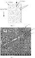
- Figs. 4A and 4B show a plan view and a cross-section view, respectively, of an A4-sized paper produced by the prior art technique.
- some microwires are exposed to the edge surface (marked by dotted circle) caused by cutting failure. In some cases, some of them stick out from the edge.
- the cutting failure caused the microwire at the edge of paper sheet to sting customer's finger in paper handling, as shown in Fig. 4B .
- the present invention provides for embedding a larger number of microwires since they are thinner than the known ones, thus, for a given thickness of a recording medium, providing a stronger detection signal.
- the technique of the present invention also provides distribution of the microwires improving the security performance.
- FIGs. 5 and 6 comparing the distribution of the microwires used in the known technique ( Fig. 5 ) and that of the present invention ( Fig. 6 ).
- the A4-sized paper in case of the present invention ( Fig. 6 ) contains much higher number of microwires with more uniform distribution of the microwires, and more random orientation defined by the tilt angle (theta) with respect to x-axis (along the long side of A4 sheet), as compared with that of the prior art technique ( Fig. 5 ).
- microwires are actually dispersed by water flow.
- most of the microwires being relatively large and heavy become almost homogeneously oriented.
- they are oriented approximately along the X-axis, being that of the water flow direction, or along the axis tilted against the water flow axis but such that the central value is just shifted and the variation in tilt angle is almost the same (i.e. the microwires are almost equally tilted resulting in substantially homogeneous orientation).
- the directionality of detecting the existence of the microwire should be reduced. This is because large Barkhausen jump happens when the effective magnetic field coincides with the wire direction. Hence, if the directionality is high (homogeneous orientation of microwires), the detection is hardly done for some zones of EAS gates; and if the randomness in the wire orientation (i.e. non-directionality) is high, large Barkhausen jump happens for any zone of EAS gate.
- the use of the above-described lighter-mass microwires of the present invention provides for increasing the randomness in the microwires orientation (i.e. orientation of their long axes). This results in the higher security performances of the recording medium carrying such microwires. Moreover, the randomness in the microwires orientation also provides for increasing the number of microwires that can be embedded in the paper.
- the present invention provides the microwires of lighter mass (caused by smaller core diameters and shorter lengths), which provides for better dispersion of microwires in water, which results in both, uniform distribution of the microwires and randomness (or quazi-randomness) of their orientation (while with narrower distribution of the tilt angle).
- the microwire of the present invention being of about 5-10 ⁇ m diameter and about 10mm length (compared to the prior art one of 30 ⁇ m diameter and 25mm length), has a mass of one order of magnitude smaller than that of the prior art.
- the present invention thus advantageously provides improved microwires dispersion which leads to an increase of the number of uniformly distributed and randomly oriented microwires in the recording medium, which causes large Barkhausen signals to be higher.
- A4 sheet more than 1000 pieces of magnetic wires, which equals to the density of more than 1.6 per square centimeter, provide sufficient detection in a commercial EAS electromagnetic gate. If the number of microwires is less than 700, which equals to the density of less than 1.1 per square centimeter, the inventors found that detection failed in some zones of the gate in several detection tests.
- the density of more than 1.6 per square centimeter should preferably be kept to provide sufficient detection in a commercial EAS electromagnetic gate.
- the inventors have manufactured the A4-sized (210mmx297mm) test paper samples with the above-described microwires (previously prepared by the above-described method).
- the samples have the same structure of the paper shown in Fig. 1 , namely including one pulp layer (12 in Fig. 1 ) with the glass-coated microwires embedded in the pulp layer and coated with the coating layer 16 on both sides of the pulp layer 12.
- the samples include different numbers of microwires, 700, 850, 1100, 1300, and 2000 microwires.
- the density of microwire in unit of per square centimeter varies from 1.1 to 3.2.
- the core diameters of microwires are chosen to be 7.5 ⁇ m, 10 ⁇ m and 15 ⁇ m, the lengths of microwires are chosen to 5, 7.5 and 10mm.
- the glass-coating thickness is 0.5 ⁇ m to 2 ⁇ m.
- the coercive force varied from 5 to 15 A/m.
- the microwire is substantially of (comparable with) the dimensions of pulp layer fiber.
- Table 1 Sample No. Diameter of Core D (micron) Length of Wire L (mm) Number of pieces N(pieces) Density of pieces (per square cm) 1 15 10 2000 3.2 2 15 10 1300 2.1 3 15 10 1100 1.8 4 15 10 850 1.4 5 15 10 700 1.1 6 15 7.5 2000 3.2 7 15 7.5 1300 2.1 8 15 7.5 1100 1.8 9 15 7.5 850 1.4 10 15 7.5 700 1.1 11 15 5 2000 3.2 12 15 5 1300 2.1 13 15 5 1100 1.8 14 15 5 850 1.4 15 15 5 700 1.1 16 10 10 2000 3.2 17 10 10 1300 2.1 18 10 10 1100 1.8 19 10 10 850 1.4 20 10 10 700 1.1 21 10 7.5 2000 3.2 22 10 7.5 1300 2.1 23 10 7.5 1100 1.8 24 10 7.5 850 1.4 25 10 7.5 700 1.1 26 10 5 2000 3.2 27 10 5 1300 2.1 28 10 5 1100 1.8
- Fig. 7 shows a microphotograph of a portion of the surface of the paper with the microwires embedded in the pulp layer.
- the pulp layer is composed of pulp fibers entangled with each other.
- the microwire 14, embedded in the pulp layer 12 has almost the same dimension as the pulp fibers PF.
- the diameter of microwire 14 is less than 20 ⁇ m.
- the width of pulp fiber is typically about 20 ⁇ m or less. This configuration may make the microwires easily embedded into single pulp layer.
- the distribution of microwires 14 was overall uniform in the entire area of A4 sized paper and the orientation of microwires was random or quasi-random, similar to that illustrated schematically in Fig.
- angle of orientation (theta) changed in average from 45 degree to 90 degree.
- the angle of orientation varied mainly from 55 degrees to 75 degrees.
- the coating glass was not broken after the paper production process, which shows that thinner glass coating is effective to prevent contamination caused by broken glass powder.
- One is Tagit EM (Electromagnetic) System, whose detection mechanism is disclosed in US 6,836,216 assigned to the assignee of the present application.
- the configuration and operation of the Gate System (as well as any other suitable detection system) do not form part of the present invention, and therefore need not be described in details.
- the Tagit EM System operates such that in the interrogation zone, an oscillating magnetic field is generated in orthogonal directions like ORTHOGONAL, FLAT, and FRONT direction.
- the soft-magnetic material used in the present invention
- passes through the interrogation zone it interacts with the oscillating magnetic field of the detection system and transmits large-Barkhausen signal to a receiving coil of the detection system.
- Fig. 8 shows the received signal waveform, related to current waveform in the transmitting coil (oscillating magnetic field).
- the top graph G 1 corresponds to the oscillating magnetic field (which for simplicity is shown as sinusoidal, while may be of any conventional waveform) and the bottom graph G 2 corresponds to the microwires' response signal.
- the oscillating magnetic field (of the Gate System) applied to the soft-magnetic material (microwires) is over the threshold level, and the soft-magnetic material transmits the pulse signal PS as a result of magnetization reversal.
- the other Gate System used in the detection test is Meto EM System, whose detection mechanism is disclosed in US 5,414,410 .
- Meto EM System whose detection mechanism is disclosed in US 5,414,410 .
- transmitting antennas generate magnetic fields of two or three different frequencies, and the nonlinear response of soft-magnetic marker results in intermodulation products of these frequencies that are detected by the signal processing unit.
- the magnetic markers are relatively small markers (0.7mm width and 35 mm typical length).
- the test paper of Koreit has this type of the marker, so it is easily detected by Meto system.
- the paper samples used in the test are the above listed 45 types of paper (Table 1). These paper samples are fabricated by changing the average number of microwires embedded in the pulp layer. The numbers chosen are 2000, 1300, 1100, 850, and 700. The corresponding densities of microwires are 3.2, 2.1, 1.8, 1.4, 1.1 in unit of per square centimeter, respectively.
- the diameter of soft-magnetic core varied from 7.5 ⁇ m to 15 ⁇ m, and the length of microwires varied from 5mm to 10mm.
- the thickness of glass coating was 0.5 ⁇ m to 2 ⁇ m.
- the magnetic coercive force was 5 to 15 A/m.
- Koreit paper which is commercially available, was used for the test.
- the Koreit paper has a two-layered structure, with 2 or 3 amorphous soft magnetic strips of amorphous soft-magnetic metal located between layers, which can be easily detected by Meto EM system.
- the width of slip is 0.7mm, the length is 35mm, and the magnetic coercive force is 5 to 30A/m.
- the test is aimed at checking the detection ability of the gate in the Tagit 2-antenna and Meto 2-antenna EM Systems for the paper being moved with a certain orientation through a certain cell inside the gate. Taking into account the practical use, the moving speed is about the walking speed of an individual.
- Fig. 9 shows that the space inside the gate (between the gate panels GP 1 and GP 2 is divided into a matrix of nine cells from 1_1 to 3 3.
- the aisle width is 75cm.
- Fig. 10 shows classification of the orientations of the paper passing through the gate.
- the orthogonal coordination system is introduced. Six types of orientation are defined for the A4-sized paper. The other two types of orientation are defined for 1/8-folded paper.
- the axes of ORT, FRONT and FLAT are defined.
- the paper orientation when the long side S 1 of the paper is parallel to ORT and the short side S 2 is parallel to FLAT is designated as ORT-FLAT.
- ORT-FLAT there are six orientations like ORT-FLAT, FLAT-ORT, ORT-FRONT, FRONT-ORT, FLAT-FRONT and FRONT-FLAT.
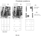
- Fig. 11 the left-hand side (position (A) ) corresponds to the back/front belt positions.
- the photo shows the situation when user holds the paper at his chest.
- the related cells are 2_1, 2_2, and 2_3.
- the related paper orientations are ORT-FLAT and FLAT-ORT.
- the center part (position (B) ) corresponds to the bag position.
- the photo shows the situation of typical paper orientation when put in bag.
- the related cells are 1_1,2_1, 3_3, 1_3,2_3, and 3_3.
- the related orientations are FLAT-FRONT and FRONT-ORT.
- the right-hand side corresponds to the pocket position.
- the upper sketch shows the situation of putting the paper 3 times folded in shirt pocket.
- the lower sketch shows the situation of putting the paper 3 times folded in pant's pocket.
- the related cells are 1_1, 1_2, 1_3, 2_1, 2_2, and 2_3.
- the related orientations are 1/8 ORT-FLAT and1/8 FLAT-ORT.
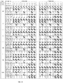
- Fig. 12 shows the results of the detection test for the above practical positions.
- the tested papers are Tagit 2000, Tagit 1300, Tagit 1100, Tagit 850, Tagit 700, and Koreit.
- the used gates are Tagit 2-antenna EM system and Meto 2-antenna EM system.
- 10 attempts were carried out, there are 30 practical positions, and thus totally 300 attempts were carried out for each test paper.
- the attempt for each orientation is repeated ten times for each cell.
- the non-practical positions, that were not tested are marked by grey.
- Fig. 13 shows the comparison of the detection ability (detectability) for 6 types of test paper.
- the test papers are samples 6 to 10, and Koreit paper.
- the diameter of metal core in the microwire is 15 ⁇ m and the length of microwire is 7.5mm.
- Two bars B 1 and B 2 are shown for each test paper.
- the left-hand bar B 1 shows the result for Meto system, and the right-hand bar B 2 shows the result for Tagit system.
- Tagit 1100 whose density of microwires is about 1.8 per square centimeter, has better performance than the prior-art (Koreit paper).
- Tagit 700 and Tagit 850 paper samples are inferior in detection. A similar behavior was observed for other paper samples containing microwire sets with different diameters of metal core (10 ⁇ m, 5 ⁇ m) and different lengths of microwire (10mm, 7.5mm).
- Fig. 14 compares the detectability for the above listed 45 paper samples with different diameters (D) of metal core (15 ⁇ m, 10 ⁇ m, and 5 ⁇ m) and different lengths (L) of microwire (10mm, 7.5mm, and 5mm), and different densities of microwires (3.2, 2.1, 1.8, 1.4, and 1.1).
- the horizontal axis indicates the sample number in Table 1 above.
- the vertical axis indicates the total number of successful detections, which corresponds (is equivalent) to the detectability.
- Square-plot B 2 indicates the result for Tagit system
- diamond plot B 1 indicates the result for Meto system.
- the detectability decreases with a decrease of microwire diameter and length D, L and the density of microwires.
- the invention provides for a freedom of choice in the diameter, length, and density of microwires, as well as uniformity in distribution and quazi-randomness in alignment/orientation (as a result of thinner and lighter microwires). This provides for optimizing the distribution (higher density, better uniformity, quazi-random orientation) of microwires of given dimensions, to thereby obtain higher detectability of microwires.
- the print test was performed for the test paper samples listed in Table 1 and Koreit paper.
- the used printers were an electro-photographic printer and an ink-jet printer. Printing was made on both sides.
- the Tagit paper showed almost the same printing quality as Koreit paper. No curling was observed after optimization of the design of the coating layer.
- the density of microwire should preferably be greater than 1.6 per square centimeter to achieve better detection as compared to the known technique. Furthermore, it is shown that the technique of the present invention provides high quality recording medium with single-layer pulp structure that can be fabricated by the conventional paper production process described before.
Description
- The invention relates to soft-magnetic microwires for use in a recording medium, which enables the presence of the recording medium to be detected in an EAS (Electronic Article Surveillance) system.
- Heretofore, various kinds of paper containing soft-magnetic microwires (tag) have been studied for the prevention of forgery, security for highly confidential information, and other purposes.
- The related-art technology for the paper mentioned is overviewed.
US 7,301,324 describes a recording medium detecting system including a magnetic field-generating unit that generates an alternating magnetic field in a predetermined particular region, a detecting unit provided close to the particular region for detecting a change in magnetic flux, and a recording medium, that is detectable by the detecting unit when placed in the particular region. The recording medium may be a two-layered or three-layered structure containing magnetic wires. In the two-layer structure, the magnetic wires are placed on one face of a substrate previously prepared and laminating another substrate hereon. In the three-layered structure a single-layered substrate (or wet paper) containing dispersed wires is sandwiched between two substrates (or wet paper) containing no wires. According to this technique, a plurality (eighteen) of 25mm-long magnetic wires are dispersed uniformly over a whole sheet of wet paper. The wire has a diameter of 30µm and a coercive force of less than 70A/m. - Further,
WO14185686 KR101341164 US2008/13212 andJP2007-177332 - There is a need in the art for a novel recording medium utilizing soft magnetic microwires for use in EAS systems. The term "recording medium" used herein refers to a structure/substrate to be printed on (e.g. a sheet of paper) by any suitable printing process such ink-jet printing, digital printing, etc.
- For the EAS detection of an object carrying magnetic wires, the number and the distribution of the magnetic wires are important factors to provide sufficiently strong detection signals. Considering the use of magnetic wires to protect a recording medium, in order to enable better printing on the recording medium, the number and the distribution of microwires are important factors to provide a flat surface of the recording medium to be printed thereon. Furthermore, the number and the distribution of microwires in are closely connected with the medium (paper) production process.
- The present invention is aimed at providing a security recording medium enabling successful detection by commercially available EM (Electromagnetic) gate systems. More specifically, the present invention is aimed at providing a security paper (exemplifying a recording medium) and is therefore described below with respect to this specific application.
- Thus, according to one aspect of the invention, it provides a recording medium, comprising: a pulp structure formed by pulp fibers, said pulp structure carrying glass-coated microwires; at least one coating layer on at least one side of said pulp structure; wherein said pulp structure is a single-layer structure with said glass-coated microwires fully embedded in said single layer, the microwires having cross-sectional dimensions approximately equal to cross-sectional dimensions of the pulp fibers.
- The microwire is configured as a soft-magnetic element, having a metal core of a predetermined material composition, and an insulating (e.g. glass) coating on said metal core. The magnetic microwire has a magnetic coercive force of 60 A/m or less (even preferably less than 20A/m, or even less than 15A/m), and has a large Barkhausen jump (discontinuity). The material composition of the metal core has nearly zero or negative magnetostriction.
- Preferably, the material composition of the metal core is Co-Fe-Si-B-Cr alloy. Preferably, the Co-Fe-Si-B-Cr alloy contains 67.7% Co, 4.3% Fe, 11% Si, 14% B, and 3% Cr by atomic percentage.
- Preferably, the length of microwire does not exceed or even preferably is less than 10 mm, being preferably 4-7.5 mm. The diameter of metal core is preferably in a range of 5-15µm. The thickness of insulating coating preferably does not exceed and even preferably is less than 3µm, is preferably in a range of 1-1.5µm.
- The microwires with the above dimensions can be properly distributed over the entire pulp layer (entire recording medium), i.e. uniformly distributed within a plane defined by the pulp layer being entirely embedded thereinside (i.e. without projecting from or exposed to the outside of the pulp layer). Also, the above microwires provide for proper orientation thereof, i.e. quazi-random orientation with respect to the longitudinal axis of the recording medium. Such distribution and orientation of the microwires of given dimensions allow for increasing the density of microwires in the pulp layer. These features provide for improving of the detectability of the microwires.
- For example, the microwires fully embedded in the single-layer pulp structure are arranged with a density of microwires higher than 1.0 per square centimeter, or higher than 2.0 per square centimeter, or even higher than 3.0 per square centimeter.
- As indicated above, the microwires fully embedded in said single-layer pulp structure are arranged with quazi-random orientation. Preferably, they are arranged with about 10 degrees variation of an angle of orientation of the microwires (their longitudinal axis).
- The recording medium may be a paper configured for printing data thereon.
- According to another broad aspect of the invention, it provides a soft-magnetic microwire having a metal core of a predetermined material composition, and an insulating coating on said metal core, wherein the metal core is Co-Fe-Si-B-Cr alloy having a magnetic coercive force less than 60 A/m, a large Barkhausen jump, and nearly zero or negative magnetostriction.
- Preferably, the length of microwire does not exceed, or even preferably is less than 10 mm, being preferably 4-7.5 mm. The diameter of metal core is preferably in a range of 5-15µm. The thickness of insulating coating preferably does not exceed and even preferably is less than 3µm, is preferably in a range of 1-1.5µm.
- According to yet another aspect of the invention, it provides a method of manufacturing the above-described paper serving as recording medium, the method comprising:
- providing a plurality of microwires, each microwire having a metal core of a predetermined material composition, and a glass coating on said metal core, wherein a diameter of the metal core substantially does not exceed 15 µm and a thickness of the glass coating substantially does not exceed 3 µm, and the material composition of the metal core is a soft-magnetic amorphous metal alloy with large Barkhausen effect, a magnetic coercive force of less than 20A/m, and nearly zero or negative magnetostriction;
- preparing a paper web on top of a fiber mesh, and distributing the microwires in the paper web;
- applying water reduction treatment to said paper web, causing a water flow through and out of the paper web, thereby dispersing the microwires and forming a single-layer pulp structure with the microwires fully embedded therein such that the microwires are arranged with substantially uniform distribution within the pulp layer, and quazi-random orientation with about 10 degrees variation of an angle of orientation of the microwires.
- In order to better understand the subject matter that is disclosed herein and to exemplify how it may be carried out in practice, embodiments will now be described, by way of non-limiting example only, with reference to the accompanying drawings, in which:
-
Fig. 1 schematically illustrates a cross-sectional view of a recording medium configured according to the principles of the invention; -
Figs. 2A and 2B schematically illustrate two examples of the known structures of a recording medium utilizing magnetic wires for security purposes, where a two-layer pulp structure is used; -
Fig. 3 illustrates schematically the main steps in the manufacture of security paper of the invention; -
Figs. 4A and 4B show schematically a plan view and a cross-section view, respectively, of an A4-sized paper produced by the prior art technique; -
Figs. 5 and6 illustrate microwires' distribution of microwire used in the known recording medium (Fig. 5 ) and in the recording medium of present invention (Fig. 6 ). -
Fig. 7 illustrates a microphotograph of a portion of the surface of the paper with the microwires embedded in the pulp layer, according to the technique of the invention; -
Figs. 8 to 12 exemplify detection of the microwires in the recording medium of the invention, whereFig. 8 shows the received signal waveform, related to current waveform in the transmitting coil (oscillating magnetic field),Fig. 9 shows partitioned gate space divided into a matrix of nine cells from 1_1 to 3_3,Fig. 10 shows classification of the orientations of the paper passing through the gate,Fig. 11 shows the practical positions which are most frequently-used positions,Fig. 12 shows the results of the detection test for these practical positions; -
Fig. 13 shows the comparison of the detection ability for 6 types of test paper; and -
Fig. 14 compares the detectability for 45 paper samples with microwires of different dimensions (diameters of metal core and lengths of microwire) and different densities of microwires. - As described above, the present invention provides a novel configuration of a recording medium (paper) secured by an arrangement (tag) of magnetic microwires, as well as the microwire structure, and a method of mass production of such recording medium.
- Referring to
Fig. 1 , there is schematically illustrated a cross-section of arecording medium 10 configured according to the principles of the invention. The recording medium includes a single pulp layer (constituting an active layer or a securing layer) 12 carrying an arrangement ofmicrowires 14, embedded inside thelayer 12, and at least oneprotective layer 16 coating theactive layer 12 at least at one side thereof. As shown in the specific not limiting example ofFig. 1 , thecoatings 16 are provided at both sides of thepulp layer 12. Themicrowires 14 are successfully distributed within the entire active layer 12 (over entire recording medium 10). As also shown in the figure, themicrowires 14 are located inside thepulp layer 12 and may even be overlapping, i.e. arranged in more than one rows one above the other. - The
recording medium 10 may be used for electro-photographic printing. Electro-photographic printing is completed by fusing a toner image on asurface 15 of the recoding medium by a rubber roll. Therefore, theprinting surface 15 of the recording medium should preferably be sufficiently smooth; otherwise, i.e. if the microwires partially project from the printing surface, this will damage a surface of fuser roll. Thus, themicrowires 14 should preferably be fully embedded in thepulp layer 12. - As further shown in
Fig. 1 , themicrowires 14 are of about 5-15µm diameter (generally, cross-sectional dimension), and the thickness of the entire recording medium 10 (single-layeractive structure 12 and double-sided coating 16) is about 80-120µm. The microwires are preferably glass-coated soft-magnetic microwires. The configuration of themicrowire 14 of the invention and its fabrication will be described more specifically further below. - Referring to
Figs. 2A and 2B , two examples of the known structures of the recording medium of the kind specified (i.e. carrying magnetic wires for security purposes) are shown, for comparison. To facilitate understanding, similar reference numbers are used for identifying the functionally common components in therecording 10 of the invention and known structures ofFigs. 2A and 2B . - In the structure of
Fig. 2A , an "active" part of the recording medium (i.e. that holds the microwires thereinside) is formed by twopulp layers 12A are 12B. This practically makes the active part (pulp structure) of recording medium relatively thick (100µm to 120µm) to prevent the microwires from being exposed. - Such thicker medium unavoidably causes defusing due to an increase of heat mass because the pulp layer mostly contributes to the heat mass. Further, in the area/region where the microwires are exposed, the toner is hardly fused because the melted toner fails to diffuse between the pulp fibers. Also, in the structure of
Fig. 2A , the microwires are glass coated wires, i.e. composed ofmagnetic core 14A and glass coating 14B. With this technique of such thick glass-coated microwires carried by a two-layer pulp structure, it is often the case that some of the microwires are only partially embedded and thus are partially projecting from the pulp structure, i.e. are exposed microwires. - In the configuration of
Fig. 2B , similar to the structure ofFig. 2A , the "active" part of the recording medium holding the microwires is formed by twostacked layers 12A and 12B and the microwires located in these layers overlap. Some of the wires ("upper" wire) 14 are embedded within the pulp layers 12A-12B, while some other wires 14' ("lower" wires) are only partially embedded and thus exposed to the medium surface. - As indicated above, partial embedding of the microwires in the recording medium impedes and practically makes it impossible to obtain high-quality printing on the surface of the recoding medium.
- As also shown in the figures, the
recording medium 10 of the present invention (Fig. 1 ) uses themicrowires 14 with smaller diameters, which facilitates full embedding (burring) of the microwires in the pulp layer and enables the recording medium thickness to be low enough. - It should be understood that, generally, the simpler the structure of a recording medium (paper), the simpler and cheaper the paper fabrication is.
- To make two-layer structure of an active part of the recording medium of the kind described above, a lower pulp layer (12B) is first prepared, then microwires are dispersed on it, and covered by an upper pulp layer (12A). Such process is described for example in
JP4529420 - Further, the known recording mediums described above utilize microwires with larger diameters (about 40µm versus 5-15µm in the medium of the present invention). Each such larger-diameter piece of microwire is relatively heavy, and accordingly dispersion is difficult to proceed. Most of such relatively heavy microwires are sunk at the bottom of a wire-dispersion tank. The yield of the microwire inclusion into the medium is very low. Furthermore, longer microwires tangle in a wire-dispersion tank, which makes the dispersion difficult. Due to relatively large mass of microwires, the wire is buried at the lower part of lower pulp layer. Sometimes, some of the microwires are exposed at the surface of medium after size press.
- The above-described
recording medium 10 of the invention shown inFig. 1 utilizes shorter andthinner microwires 14 which enables uniform dispersion and complete embedding thereof within onepulp layer 12 and complete coverage by aprotective coating 16. This enables therecording medium 10 of the invention to be more reliable for electro-photographic printing and higher protection for the prevention of forgery, security for highly confidential information. - The improvement of security is in that it is harder to see the microwires, i.e. microwires are practically not exposed to viewer at all. This means people are less likely to pull and /or the microwires out from the medium.
- The following is the description of the possible configuration of the soft-
magnetic microwire 14 of the invention. The soft-magnetic microwire 14 of an exemplary embodiment of the invention for use in a recording medium is capable of emitting large Barkhausen signals, which are caused by magnetization reversal, detectable with an EAS detector (typically, incorporated in a gate assembly). The microwire structure includes a soft-magnetic metal core coated with an insulating material, like a glass. - Glass coated microwires with amorphous metal cores have been developed and are described disclosed with a patent
US 6,441,737 . The inventor of the present application is a co-inventor inUS 6,441,737 . The material for the metal core is a cobalt-base alloy. For example, Co-Fe-Si-B alloy (e.g., containing 77.5% Co, 4.5% Fe, 12% Si, and 6% B by atomic percentage), Co-Fe-Si-B-Cr alloy (e.g., containing 68.7% Co, 3.8% Fe, 12.3% Si, 11.4% B, and 3.8% Cr by atomic percentage), or Co-Fe-Si-B-Cr-Mo alloy (e.g., containing 68.6% Co, 4.2% Fe, 12.6% Si, 11% B, 3.52% Cr and 0.08% Mo by atomic percentage) may be used. - As described below, it is desired that the soft-magnetic metal core has nearly zero or negative magnetostriction. The inventors of the present invention have found that, for the purposes of paper-like recording medium production, if the metal core in soft-magnetic microwires has positive magnetostriction, the large Barkhausen signal will be reduced or at worst diminished by the mechanical stress induced by the paper production process. The stress is typically applied after the paper production. For example, the pulp fiber elongates due to moisture and shrinks due to drying. The microwires are under such a stress in the pulp layer. On the other hand, when the soft-magnetic metal core has nearly zero or negative magnetostriction, the large Barkhausen signal will be more stable under stress applied on the microwires.
- By controlling the alloy component, nearly zero or negative magnetostriction can be achieved. For example, while Co-Fe-Si-B-Cr alloy containing 67% Co, 5% Fe, 11% Si, 14% B, and 3% Cr by atomic percentage shows positive magnetostriction, Co-Fe-Si-B-Cr alloy containing 67.7% Co, 4.3% Fe, 11% Si, 14% B, and 3% Cr by atomic percentage shows nearly zero magnetostriction.
- The diameter of the metal core in microwires of the current invention, which is especially useful for security paper, can be in a range of 5-15µm. The thickness of insulating material (e.g. glass) substantially does not exceed and is preferably less than 2µm, preferably about 1.5µm. This is because thicker (more than 3µm thick) glass coating is practically fragile to mechanical stress applied during paper production and also paper handling in the printing and/or copying machine like an electro-photographic printer. When glass is broken in the paper production machine and/or the printing machine, glass particles contaminate inside the parts of the machine, which may increase machine maintenance cost due to the shortened cleaning cycle. The present invention provides for using thinner glass coating which makes the microwire more flexible, and thus preventing the glass breaking effects.
- The glass-coated microwire may be fabricated using the continuous Taylor-Ulitovsky method, which is disclosed in
US 8,978,415 , and then cut into pieces with the lengths of about 10 mm or less, preferably 4 mm to 7.5 mm. - The following is the description of an example of the manufacturing process for manufacturing the recording medium of the present invention.
- The manufacturing process utilizes well-known paper making techniques used for paper production for making graphic paper (i. e., paper suitable for office and printing) today. The main stages of such process are known per se and do not form part of the invention, and therefore need not be specifically described.
Fig. 3 illustrates aflow chart 100 of the main steps/stages in the process of manufacturing the security paper, as follows: - The microwires of desired dimensions (metal core diameter and length) are prepared using the above-mentioned Taylor-Ulitovsky continuous method and cutting into pieces (step 102). The paper web is separately prepared (step 104) using the known technique. Briefly, pulpwood arrives at a paper mill in the form of very thick sheets and recovered paper normally arrives in the form of large, compressed bales. Both these materials have to be broken down so that the individual fibers they contain are completely separated from each other. This process is performed in large vessels, known as 'pulpers', where the raw materials are diluted with water and then subjected to violent mechanical action using steel rotor blades. The resulting papermaking stock is then passed to holding tanks. During this preliminary stage, auxiliary chemicals and additives may be added. The auxiliary chemicals are usually combined with the fibrous raw materials and can be sizing agents, which reduce ink and water penetration, and process anti-foaming agents. The stock is then pumped through various types of mechanical cleaning equipment to the paper machine. On the paper machine, more water is added to produce a fiber suspension and the resulting mixture is passed into a head-box which squirts it through a thin, horizontal slit across the full machine width on to a moving, endless wire mesh.
- Then, a water reduction treatment is applied (sheet formation process), during which the microwires are dispersed in the pulp layer (step 106). During the water removal, the fibers start to spread and consolidate into a thin mat, forming a layer of paper on top of the wire mesh. This web of wet paper is then lifted from the wire mesh and squeezed between a series of presses where its water content is lowered to about 50%. It then passes around a series of cast-iron cylinders, heated to temperatures in excess of 100°C, where drying takes place. Here, the water content is lowered to its final level (to between 5% and 8%). Throughout its passage from the wire mesh to the drying operation, the paper web is supported by various types of endless fabric belts moving at the same speed. After drying, some papers may also undergo surface treatments, e.g. sizing and calendaring - smoothing the surface of the paper by passing it between a series of rotating, polished, metal rollers to produce a glazed or glossy appearance. The paper may then be wound into a reel.
- According to the invention, during the above water reduction treatment, the microwires (configured as described above) are distributed uniformly with proper orientation and density in the paper web (step 108). This will be described more specifically further below. The paper web provides a base which fixes the microwires on its smooth and soft surface. When it is size pressed, the microwires are buried (fully embedded) inside the pulp fibers.
- Then, coating is applied on both sides of the paper layer (pulp layer) containing microwires (step 110). The pulp layer, when contains microwires embedded therein, presents an active securing layer detectable by a magnetic reader/detector (gate).
- The coating has several functions, as follows. It prevents the microwires from being exposed at the surface, from leaving the pulp layer (escaping therefrom), from being identified easily. Also, the coating enables toner or ink to diffuse easily inside during fusing or drying, and enables to provide friction force for paper handling in a copy machine and printer.
- Thus, the coating materials are properly selected to provide the above functions. The following is the description of an example of the candidates for coating material composition is described below.
- Coating takes place on size press after the paper web is created and partially dried. A coating bath contains mixture of natural binder (starch, PVOH, carboxymethylcellulose) and synthetic latex (styrenebutadien, styreneacrylic, vinylacetate). The ratio of these two compounds may be about (approximately) 10 to 80 parts of natural binder (depending on the binder used) and approximately 40 to 70 parts of synthetic latex (expressed as dry weight). The coating bath may also contain other materials, like mineral filler, antistatic agent, whitening agent, dye and other functional chemicals usually used for surface treatment of paper. Total solids content of the coating bath is in a range of about 4 to 20%. Pickup of solids on size press is about 1.5 to 4 gsm per one side of paper.
- A final form is paper roll which winds a paper sheet composed of one pulp layer (12 in
Fig. 1 ) with themicrowires 14 dispersed and acoating layer 16. Paper roll may then is cut by the blade into each sheet of the record medium (step 112). The density of the microwires in the paper sheet may be verified (step 114); and the paper sheets may be properly packaged (step 116). - For comparison, let us consider the prior art techniques of the kind specified. In the prior art techniques, the blade is deteriorated fast because of thick metal core and thick glass coating of the wires. A resulting short life of blade make the paper production process more expensive, and causes the cutting failure which left the microwires out from the surface of cut cross-section. This is illustrated schematically in
Figs. 4A and 4B which show a plan view and a cross-section view, respectively, of an A4-sized paper produced by the prior art technique. As shown, some microwires are exposed to the edge surface (marked by dotted circle) caused by cutting failure. In some cases, some of them stick out from the edge. The cutting failure caused the microwire at the edge of paper sheet to sting customer's finger in paper handling, as shown inFig. 4B . - Turning back to
Fig. 1 , it is clearly shown that all the above problems are solved in the recording medium of the invention, since the microwires of the invention are thinner, due to thinner metal core and thinner glass coating used in the microwires of the present invention. - As indicated above, for the proper detection of the microwires embedded in the recording medium, such factors as number of microwires and their distribution in the recording medium are important. With regard to the number of microwires, it is evident that for a given paper size, the present invention provides for embedding a larger number of microwires since they are thinner than the known ones, thus, for a given thickness of a recording medium, providing a stronger detection signal. The technique of the present invention also provides distribution of the microwires improving the security performance.
- In this connection, reference is made to
Figs. 5 and6 comparing the distribution of the microwires used in the known technique (Fig. 5 ) and that of the present invention (Fig. 6 ). As shown, the A4-sized paper, in case of the present invention (Fig. 6 ) contains much higher number of microwires with more uniform distribution of the microwires, and more random orientation defined by the tilt angle (theta) with respect to x-axis (along the long side of A4 sheet), as compared with that of the prior art technique (Fig. 5 ). - In this connection, the following should be noted. The microwires are actually dispersed by water flow. In the conventional techniques, most of the microwires, being relatively large and heavy become almost homogeneously oriented. In some cases they are oriented approximately along the X-axis, being that of the water flow direction, or along the axis tilted against the water flow axis but such that the central value is just shifted and the variation in tilt angle is almost the same (i.e. the microwires are almost equally tilted resulting in substantially homogeneous orientation).
- The inventors have found that from the security point of view, the directionality of detecting the existence of the microwire should be reduced. This is because large Barkhausen jump happens when the effective magnetic field coincides with the wire direction. Hence, if the directionality is high (homogeneous orientation of microwires), the detection is hardly done for some zones of EAS gates; and if the randomness in the wire orientation (i.e. non-directionality) is high, large Barkhausen jump happens for any zone of EAS gate.
- Therefore, the use of the above-described lighter-mass microwires of the present invention provides for increasing the randomness in the microwires orientation (i.e. orientation of their long axes). This results in the higher security performances of the recording medium carrying such microwires. Moreover, the randomness in the microwires orientation also provides for increasing the number of microwires that can be embedded in the paper.
- Thus, the present invention provides the microwires of lighter mass (caused by smaller core diameters and shorter lengths), which provides for better dispersion of microwires in water, which results in both, uniform distribution of the microwires and randomness (or quazi-randomness) of their orientation (while with narrower distribution of the tilt angle). The microwire of the present invention, being of about 5-10µm diameter and about 10mm length (compared to the prior art one of 30 µm diameter and 25mm length), has a mass of one order of magnitude smaller than that of the prior art.
- The present invention thus advantageously provides improved microwires dispersion which leads to an increase of the number of uniformly distributed and randomly oriented microwires in the recording medium, which causes large Barkhausen signals to be higher. In the case of A4 sheet, more than 1000 pieces of magnetic wires, which equals to the density of more than 1.6 per square centimeter, provide sufficient detection in a commercial EAS electromagnetic gate. If the number of microwires is less than 700, which equals to the density of less than 1.1 per square centimeter, the inventors found that detection failed in some zones of the gate in several detection tests. For a paper sheet larger than A4-size, the density of more than 1.6 per square centimeter should preferably be kept to provide sufficient detection in a commercial EAS electromagnetic gate.
- The following are some practical examples for the fabrication of paper with microwires and detection of microwires.
- The inventors have manufactured the A4-sized (210mmx297mm) test paper samples with the above-described microwires (previously prepared by the above-described method). The samples have the same structure of the paper shown in
Fig. 1 , namely including one pulp layer (12 inFig. 1 ) with the glass-coated microwires embedded in the pulp layer and coated with thecoating layer 16 on both sides of thepulp layer 12. The samples include different numbers of microwires, 700, 850, 1100, 1300, and 2000 microwires. The density of microwire in unit of per square centimeter varies from 1.1 to 3.2. The core diameters of microwires are chosen to be 7.5µm, 10µm and 15µm, the lengths of microwires are chosen to 5, 7.5 and 10mm. The glass-coating thickness is 0.5µm to 2µm. The coercive force varied from 5 to 15 A/m. In all the examples, with the microwires of diameter less than 20µm, the microwire is substantially of (comparable with) the dimensions of pulp layer fiber. - The characteristics of 45 types of the test paper are summarized in the following Table 1:
Table 1 Sample No. Diameter of Core D (micron) Length of Wire L (mm) Number of pieces N(pieces) Density of pieces (per square cm) 1 15 10 2000 3.2 2 15 10 1300 2.1 3 15 10 1100 1.8 4 15 10 850 1.4 5 15 10 700 1.1 6 15 7.5 2000 3.2 7 15 7.5 1300 2.1 8 15 7.5 1100 1.8 9 15 7.5 850 1.4 10 15 7.5 700 1.1 11 15 5 2000 3.2 12 15 5 1300 2.1 13 15 5 1100 1.8 14 15 5 850 1.4 15 15 5 700 1.1 16 10 10 2000 3.2 17 10 10 1300 2.1 18 10 10 1100 1.8 19 10 10 850 1.4 20 10 10 700 1.1 21 10 7.5 2000 3.2 22 10 7.5 1300 2.1 23 10 7.5 1100 1.8 24 10 7.5 850 1.4 25 10 7.5 700 1.1 26 10 5 2000 3.2 27 10 5 1300 2.1 28 10 5 1100 1.8 29 10 5 850 1.4 30 10 5 700 1.1 31 5 10 2000 3.2 32 5 10 1300 2.1 33 5 10 1100 1.8 34 5 10 850 1.4 35 5 10 700 1.1 36 5 7.5 2000 3.2 37 5 7.5 1300 2.1 38 5 7.5 1100 1.8 39 5 7.5 850 1.4 40 5 7.5 700 1.1 41 5 5 2000 3.2 42 5 5 1300 2.1 43 5 5 1100 1.8 44 5 5 850 1.4 45 5 5 700 1.1 -
Fig. 7 shows a microphotograph of a portion of the surface of the paper with the microwires embedded in the pulp layer. The pulp layer is composed of pulp fibers entangled with each other. As shown in the figure, themicrowire 14, embedded in thepulp layer 12, has almost the same dimension as the pulp fibers PF. The diameter ofmicrowire 14 is less than 20µm. The width of pulp fiber is typically about 20µm or less. This configuration may make the microwires easily embedded into single pulp layer. Although not seen inFig. 7 , the distribution ofmicrowires 14 was overall uniform in the entire area of A4 sized paper and the orientation of microwires was random or quasi-random, similar to that illustrated schematically inFig. 6 , that is, angle of orientation (theta) changed in average from 45 degree to 90 degree. Under the paper mill machine speed of 45 to 65 m/min, the angle of orientation varied mainly from 55 degrees to 75 degrees. Also, the coating glass was not broken after the paper production process, which shows that thinner glass coating is effective to prevent contamination caused by broken glass powder. - The inventors ran the detection test using two types of a commercial EAS electromagnetic gate. One is Tagit EM (Electromagnetic) System, whose detection mechanism is disclosed in
US 6,836,216 assigned to the assignee of the present application. The configuration and operation of the Gate System (as well as any other suitable detection system) do not form part of the present invention, and therefore need not be described in details. Briefly, the Tagit EM System operates such that in the interrogation zone, an oscillating magnetic field is generated in orthogonal directions like ORTHOGONAL, FLAT, and FRONT direction. When the soft-magnetic material (used in the present invention) passes through the interrogation zone, it interacts with the oscillating magnetic field of the detection system and transmits large-Barkhausen signal to a receiving coil of the detection system. -
Fig. 8 shows the received signal waveform, related to current waveform in the transmitting coil (oscillating magnetic field). In the figure, the top graph G1 corresponds to the oscillating magnetic field (which for simplicity is shown as sinusoidal, while may be of any conventional waveform) and the bottom graph G2 corresponds to the microwires' response signal. The oscillating magnetic field (of the Gate System) applied to the soft-magnetic material (microwires) is over the threshold level, and the soft-magnetic material transmits the pulse signal PS as a result of magnetization reversal. - The other Gate System used in the detection test is Meto EM System, whose detection mechanism is disclosed in
US 5,414,410 . Generally, in such Gate System, transmitting antennas generate magnetic fields of two or three different frequencies, and the nonlinear response of soft-magnetic marker results in intermodulation products of these frequencies that are detected by the signal processing unit. The magnetic markers are relatively small markers (0.7mm width and 35 mm typical length). The test paper of Koreit has this type of the marker, so it is easily detected by Meto system. - In the detection tests, the same distance of 75cm between the gate panels (as used in Tagit EM system) was used for both detection systems.
- The paper samples used in the test are the above listed 45 types of paper (Table 1). These paper samples are fabricated by changing the average number of microwires embedded in the pulp layer. The numbers chosen are 2000, 1300, 1100, 850, and 700. The corresponding densities of microwires are 3.2, 2.1, 1.8, 1.4, 1.1 in unit of per square centimeter, respectively. The diameter of soft-magnetic core varied from 7.5µm to 15µm, and the length of microwires varied from 5mm to 10mm. The thickness of glass coating was 0.5µm to 2µm. The magnetic coercive force was 5 to 15 A/m.
- For reference, Koreit paper, which is commercially available, was used for the test. The Koreit paper has a two-layered structure, with 2 or 3 amorphous soft magnetic strips of amorphous soft-magnetic metal located between layers, which can be easily detected by Meto EM system. The width of slip is 0.7mm, the length is 35mm, and the magnetic coercive force is 5 to 30A/m.
- The test is aimed at checking the detection ability of the gate in the Tagit 2-antenna and Meto 2-antenna EM Systems for the paper being moved with a certain orientation through a certain cell inside the gate. Taking into account the practical use, the moving speed is about the walking speed of an individual.
-
Fig. 9 shows that the space inside the gate (between the gate panels GP1 and GP2 is divided into a matrix of nine cells from 1_1 to 3 3. The aisle width is 75cm.Fig. 10 shows classification of the orientations of the paper passing through the gate. The orthogonal coordination system is introduced. Six types of orientation are defined for the A4-sized paper. The other two types of orientation are defined for 1/8-folded paper. The axes of ORT, FRONT and FLAT are defined. The paper orientation when the long side S1 of the paper is parallel to ORT and the short side S2 is parallel to FLAT is designated as ORT-FLAT. Thus, there are six orientations like ORT-FLAT, FLAT-ORT, ORT-FRONT, FRONT-ORT, FLAT-FRONT and FRONT-FLAT. - Before the test, the practical positions which are most frequently-used positions are defined, as shown in
Fig. 11 . InFig. 11 , the left-hand side (position (A)) corresponds to the back/front belt positions. The photo shows the situation when user holds the paper at his chest. The related cells are 2_1, 2_2, and 2_3. The related paper orientations are ORT-FLAT and FLAT-ORT. The center part (position (B)) corresponds to the bag position. The photo shows the situation of typical paper orientation when put in bag. The related cells are 1_1,2_1, 3_3, 1_3,2_3, and 3_3. The related orientations are FLAT-FRONT and FRONT-ORT. The right-hand side (position (C)) corresponds to the pocket position. The upper sketch shows the situation of putting thepaper 3 times folded in shirt pocket. The lower sketch (position (D)) shows the situation of putting thepaper 3 times folded in pant's pocket. The related cells are 1_1, 1_2, 1_3, 2_1, 2_2, and 2_3. The related orientations are 1/8 ORT-FLAT and1/8 FLAT-ORT. -
Fig. 12 shows the results of the detection test for the above practical positions. The tested papers are Tagit 2000,Tagit 1300, Tagit 1100, Tagit 850, Tagit 700, and Koreit. The used gates are Tagit 2-antenna EM system and Meto 2-antenna EM system. For each practical position, 10 attempts were carried out, there are 30 practical positions, and thus totally 300 attempts were carried out for each test paper. The attempt for each orientation is repeated ten times for each cell. In the figure, the non-practical positions, that were not tested are marked by grey. -
Fig. 13 shows the comparison of the detection ability (detectability) for 6 types of test paper. The test papers are samples 6 to 10, and Koreit paper. The diameter of metal core in the microwire is 15µm and the length of microwire is 7.5mm. Two bars B1 and B2 are shown for each test paper. The left-hand bar B1 shows the result for Meto system, and the right-hand bar B2 shows the result for Tagit system. - As can be seen, detectability of the secured paper of the present invention (Tagit paper) configured as described above increases with an increase of the density of microwires. The Tagit 1100, whose density of microwires is about 1.8 per square centimeter, has better performance than the prior-art (Koreit paper). On the other hand, Tagit 700 and Tagit 850 paper samples are inferior in detection. A similar behavior was observed for other paper samples containing microwire sets with different diameters of metal core (10µm, 5µm) and different lengths of microwire (10mm, 7.5mm).
-
Fig. 14 compares the detectability for the above listed 45 paper samples with different diameters (D) of metal core (15µm, 10µm, and 5µm) and different lengths (L) of microwire (10mm, 7.5mm, and 5mm), and different densities of microwires (3.2, 2.1, 1.8, 1.4, and 1.1). The horizontal axis indicates the sample number in Table 1 above. The vertical axis indicates the total number of successful detections, which corresponds (is equivalent) to the detectability. Square-plot B2 indicates the result for Tagit system, and diamond plot B1 indicates the result for Meto system. Nine sets S1 -S9 are shown, each for five plots for different 5 samples, where sets S1-S3 correspond to microwires having diameter D=15µm and lengths 10mm, 7.5mm, and 5mm respectively; sets S4-S6 correspond to microwires having diameter D=10µm and lengths 10mm, 7.5mm, and 5mm respectively; and sets S7-S9 correspond to microwires having diameter D=7.5µm and lengths 10mm, 7.5mm, and 5mm respectively. These graphs show that for the microwire dimensions (D,L) = (15,10), i.e. set S1, the detectability decreases with a decrease of the density of microwires. A similar behavior was observed for the microwires (D,L) = (15,7.5), i.e. set S2 . From this set, along with a decrease of the length of wire, the detectability decreases. A similar behavior was observed for microwires (D,L) = (15,5.0), whose plots are indicated by the third five-plot set S3 . The fourth set S4 of five plots correspond to microwires (D,L) = (10,10), which show that the detectability decreases with decrease of the diameter of the core metal. The effect of the decrease in the diameter D on the detectability is to parallel shift the polygonal line downwards. For example with L=15mm, when the diameter D is decreased from 15µm to 10µm, the polygonal line from the first set of 5 plots shifts to the polygonal line from the fourth set of 5 plots with a slope kept constant. - Summarizing the results, the detectability decreases with a decrease of microwire diameter and length D, L and the density of microwires. For example, as shown in
Fig. 14 , to achieve the detectability of over 200, in the case of microwires of diameter D=15µm, the length of microwire can be decreased to 5mm, which makes the distribution of microwires more uniform due to lighter mass (as described above); in the case of microwires of diameter D=10µm, the length of microwire can be decreased to 7.5mm; and in the case of microwires of diameter D=5µm, the length of microwire can be decreased to 10mm. Therefore, for the same required detectability to be obtained, the invention provides for a freedom of choice in the diameter, length, and density of microwires, as well as uniformity in distribution and quazi-randomness in alignment/orientation (as a result of thinner and lighter microwires). This provides for optimizing the distribution (higher density, better uniformity, quazi-random orientation) of microwires of given dimensions, to thereby obtain higher detectability of microwires. - The print test was performed for the test paper samples listed in Table 1 and Koreit paper. The used printers were an electro-photographic printer and an ink-jet printer. Printing was made on both sides. The Tagit paper showed almost the same printing quality as Koreit paper. No curling was observed after optimization of the design of the coating layer.
- From the above results, it is evident that the density of microwire should preferably be greater than 1.6 per square centimeter to achieve better detection as compared to the known technique. Furthermore, it is shown that the technique of the present invention provides high quality recording medium with single-layer pulp structure that can be fabricated by the conventional paper production process described before.
Claims (8)
- A recording medium being a security paper configured for printing data thereon, the recording medium comprising:a web structure formed by web fibers, said web structure carrying microwires having a metal core of a predetermined material composition of soft-magnetic amorphous metal alloy and an insulating glass layer coating on said metal core, the metal core being capable of transmitting a detectable signal when interacting with an oscillating magnetic field and having a magnetic coercive force of less than 20A/m and nearly zero or negative magnetostriction; andat least one coating layer on at least one side of said web structure;wherein said web structure comprises a single-layer structure comprising the web fibers and wherein, to improve detectability of microwires the microwires are fully embedded in said single-layer structure and have a diameter of the metal core in a range of 5-15µm and a length not exceeding 10mm, , and said microwires are substantially uniformly distributed within a plane defined by said single layer and arranged with quazi-random orientation with respect to a longitudinal axis of said single layer to provide an arrangement of the microwires in said single layer with a density of the microwires higher than 1.0 per square centimeter.
- A recording medium of claim 1, wherein the microwires are arranged with 10 degrees variation of an angle of orientation of the microwires with respect to the longitudinal axis of said layer.
- A recording medium according to claim 1, wherein said insulating glass coating has a thickness not exceeding 3 µm.
- A recording medium according to claim 2, wherein the thickness of the glass coating is in a range of 0.5-1.5µm.
- A recording medium according to any one of claims 1 to 3, wherein said material composition of the metal core has a magnetic coercive force in a range of 2-10A/m.
- A recording medium according to any one of claims 1 to 4, wherein the material composition of the metal core is Co-Fe-Si-B-Cr alloy, containing 67.7% Co, 4.3% Fe, 11% Si, 14% B, and 3% Cr by atomic percentage.
- A recording medium according to any one of claims 1 to 5, wherein the microwires fully embedded in said single-layer structure are arranged with the density of microwires higher than 2.0 per square centimeter or higher than 3.0 per square centimeter.
- A method of manufacturing the recording medium of any one of claims 1 to 5, the method comprising:providing a plurality of microwires, each microwire having a metal core and a glass coating on said metal core, the metal core being of a predetermined material composition comprising soft-magnetic amorphous metal alloy with a magnetic coercive force of less than 20A/m and nearly zero or negative magnetostriction, and being capable of transmitting a detectable signal when interacting with an oscillating magnetic field, wherein said plurality of microwires have a diameter of the metal core in a range of 5-15µm, a length of the microwires not exceeding 10mm, and a thickness of the glass coating not exceeding 3µm;preparing a paper web on top of a fiber mesh, and distributing the microwires in the paper web;applying water reduction treatment to said paper web, causing a water flow through and out of the paper web, thereby dispersing the microwires and forming a single-layer web structure with said microwires being fully embedded therein such that the microwires are arranged with uniform distribution within a plane of the web layer, and quazi-random orientation with 10 degrees variation of an angle of orientation of the microwires with respect to a longitudinal axis of said layer.
Applications Claiming Priority (2)
| Application Number | Priority Date | Filing Date | Title |
|---|---|---|---|
| US201562149845P | 2015-04-20 | 2015-04-20 | |
| PCT/IL2016/050403 WO2016170527A1 (en) | 2015-04-20 | 2016-04-18 | Recording medium |
Publications (2)
| Publication Number | Publication Date |
|---|---|
| EP3286758A1 EP3286758A1 (en) | 2018-02-28 |
| EP3286758B1 true EP3286758B1 (en) | 2020-07-15 |
Family
ID=56087478
Family Applications (1)
| Application Number | Title | Priority Date | Filing Date |
|---|---|---|---|
| EP16725942.3A Active EP3286758B1 (en) | 2015-04-20 | 2016-04-18 | Recording medium |
Country Status (6)
| Country | Link |
|---|---|
| US (1) | US10392753B2 (en) |
| EP (1) | EP3286758B1 (en) |
| JP (1) | JP7219004B2 (en) |
| KR (1) | KR101930935B1 (en) |
| CN (1) | CN106257981B (en) |
| WO (1) | WO2016170527A1 (en) |
Families Citing this family (7)
| Publication number | Priority date | Publication date | Assignee | Title |
|---|---|---|---|---|
| ES2581127B2 (en) * | 2016-04-13 | 2017-05-04 | Universidad Complutense De Madrid | Label, system and method for long-distance object detection |
| EP3649288A4 (en) * | 2017-07-05 | 2021-01-27 | Tagit S.A. | Method for production of security paper |
| CN110466248A (en) * | 2018-05-10 | 2019-11-19 | 素材的脉有限公司 | The safety of imager recording medium recognition unit |
| KR101961068B1 (en) * | 2018-09-17 | 2019-03-21 | 주식회사 한엘 | Method for manufacturing security film using weaved soft-magnetic metal fabrics |
| RU2725755C1 (en) * | 2020-01-31 | 2020-07-06 | Александр Николаевич Шалыгин | Machine-readable identification mark based on amorphous microwire for paper sheet material on cellulose base |
| KR102497168B1 (en) * | 2021-04-20 | 2023-02-07 | 주식회사 소재의맥 | Writing/reading medium for preventing leakage of hard copy |
| CN114953806B (en) * | 2022-06-06 | 2023-05-12 | 吉安法博非晶科技有限公司 | Magnetic microfilaments and security media |
Family Cites Families (20)
| Publication number | Priority date | Publication date | Assignee | Title |
|---|---|---|---|---|
| GB9302757D0 (en) | 1993-02-11 | 1993-03-24 | Esselte Meto Int Gmbh | Method and system for detecting a marker |
| JP3211543B2 (en) * | 1994-03-02 | 2001-09-25 | 王子製紙株式会社 | Security paper |
| IL131866A0 (en) * | 1999-09-10 | 2001-03-19 | Advanced Coding Systems Ltd | A glass-coated amorphous magnetic microwire marker for article surveillance |
| US6747559B2 (en) * | 1999-09-10 | 2004-06-08 | Advanced Coding Systems Ltd. | Glass-coated amorphous magnetic mircowire marker for article surveillance |
| US6836216B2 (en) | 2002-05-09 | 2004-12-28 | Electronic Article Surveillance Technologies, Ltd. | Electronic article surveillance system |
| JP4529420B2 (en) | 2003-11-18 | 2010-08-25 | 富士ゼロックス株式会社 | Security paper and method and apparatus for manufacturing the same |
| JP4807065B2 (en) * | 2005-12-22 | 2011-11-02 | 富士ゼロックス株式会社 | Recording medium and manufacturing method thereof |
| JP4983019B2 (en) * | 2005-12-26 | 2012-07-25 | 富士ゼロックス株式会社 | Paper manufacturing method, paper manufacturing apparatus |
| JP4956993B2 (en) | 2005-12-26 | 2012-06-20 | 富士ゼロックス株式会社 | Recording medium detection system |
| JP2007177361A (en) * | 2005-12-27 | 2007-07-12 | Fuji Xerox Co Ltd | Magnetic wire and printing paper containing the magnetic wire |
| JP4847191B2 (en) * | 2006-04-14 | 2011-12-28 | 富士ゼロックス株式会社 | Recording sheet |
| CN100417528C (en) * | 2006-05-10 | 2008-09-10 | 中国乐凯胶片集团公司 | Heat-sensitive magnetic recording paper |
| JP2008020579A (en) * | 2006-07-12 | 2008-01-31 | Fuji Xerox Co Ltd | Magnetic material wire and recording medium |
| JP4916239B2 (en) * | 2006-07-21 | 2012-04-11 | 富士ゼロックス株式会社 | Recording medium and sheet |
| IL188559A0 (en) | 2008-01-03 | 2008-11-03 | D T N R Ltd | Method of production of glass coated metal wires and metal microwires |
| JP5640702B2 (en) | 2010-12-02 | 2014-12-17 | 富士ゼロックス株式会社 | Paper |
| JP5799566B2 (en) * | 2011-04-26 | 2015-10-28 | 富士ゼロックス株式会社 | Paper |
| JP5910048B2 (en) * | 2011-12-06 | 2016-04-27 | 富士ゼロックス株式会社 | Paper and paper manufacturing method |
| KR101341164B1 (en) | 2013-05-16 | 2013-12-13 | (주)티엔에프 | Writing/reading means for security |
| KR101738341B1 (en) | 2014-12-31 | 2017-05-22 | 주식회사 소재의맥 | Writing/reading means for security |
-
2016
- 2016-04-18 WO PCT/IL2016/050403 patent/WO2016170527A1/en active Application Filing
- 2016-04-18 KR KR1020167015606A patent/KR101930935B1/en active IP Right Grant
- 2016-04-18 CN CN201680000726.2A patent/CN106257981B/en active Active
- 2016-04-18 JP JP2017516953A patent/JP7219004B2/en active Active
- 2016-04-18 EP EP16725942.3A patent/EP3286758B1/en active Active
- 2016-04-18 US US15/568,042 patent/US10392753B2/en active Active
Non-Patent Citations (1)
| Title |
|---|
| None * |
Also Published As
| Publication number | Publication date |
|---|---|
| JP7219004B2 (en) | 2023-02-07 |
| US10392753B2 (en) | 2019-08-27 |
| CN106257981A (en) | 2016-12-28 |
| EP3286758A1 (en) | 2018-02-28 |
| US20180142423A1 (en) | 2018-05-24 |
| JP2018513283A (en) | 2018-05-24 |
| KR101930935B1 (en) | 2018-12-20 |
| KR20160140573A (en) | 2016-12-07 |
| CN106257981B (en) | 2020-01-07 |
| WO2016170527A1 (en) | 2016-10-27 |
Similar Documents
| Publication | Publication Date | Title |
|---|---|---|
| EP3286758B1 (en) | Recording medium | |
| CN101109913B (en) | Recording medium and sheet | |
| JP2008020579A (en) | Magnetic material wire and recording medium | |
| KR101775526B1 (en) | Printing paper distinguish device unit of image forming system for maintenance of public security | |
| KR101743823B1 (en) | Writing/reading papers for security | |
| EP2184726A1 (en) | Label Sheet | |
| EP3649288A1 (en) | Method for production of security paper | |
| JP2006277641A (en) | Ic chip interior sheet | |
| US20090173463A1 (en) | Security paper material, in particular for labelling and packaging, and manufacturing method thereof | |
| JP2011504423A (en) | Method of manufacturing a substrate for reinforced applied abrasive products and products obtained thereby | |
| KR20200130001A (en) | Writing/reading means for security and preparing method thereof | |
| KR102497168B1 (en) | Writing/reading medium for preventing leakage of hard copy | |
| JPH10272735A (en) | Magnetic material-containing laminate sheet | |
| US20070259175A1 (en) | Tape with Built-In Ic Chip, Production Method Thereof, and Sheet with Built-In Ic Chip | |
| KR20220054778A (en) | Security paper having wires | |
| KR20220059451A (en) | Security paper having wires | |
| JP2024036356A (en) | Security paper and security paper manufacturing method | |
| KR20220054779A (en) | Security paper having wires | |
| KR20170138846A (en) | Security paper and manufacturing method threrof |
Legal Events
| Date | Code | Title | Description |
|---|---|---|---|
| STAA | Information on the status of an ep patent application or granted ep patent |
Free format text: STATUS: THE INTERNATIONAL PUBLICATION HAS BEEN MADE |
|
| PUAI | Public reference made under article 153(3) epc to a published international application that has entered the european phase |
Free format text: ORIGINAL CODE: 0009012 |
|
| STAA | Information on the status of an ep patent application or granted ep patent |
Free format text: STATUS: REQUEST FOR EXAMINATION WAS MADE |
|
| 17P | Request for examination filed |
Effective date: 20171116 |
|
| AK | Designated contracting states |
Kind code of ref document: A1 Designated state(s): AL AT BE BG CH CY CZ DE DK EE ES FI FR GB GR HR HU IE IS IT LI LT LU LV MC MK MT NL NO PL PT RO RS SE SI SK SM TR |
|
| AX | Request for extension of the european patent |
Extension state: BA ME |
|
| DAV | Request for validation of the european patent (deleted) | ||
| DAX | Request for extension of the european patent (deleted) | ||
| STAA | Information on the status of an ep patent application or granted ep patent |
Free format text: STATUS: EXAMINATION IS IN PROGRESS |
|
| 17Q | First examination report despatched |
Effective date: 20180910 |
|
| GRAP | Despatch of communication of intention to grant a patent |
Free format text: ORIGINAL CODE: EPIDOSNIGR1 |
|
| STAA | Information on the status of an ep patent application or granted ep patent |
Free format text: STATUS: GRANT OF PATENT IS INTENDED |
|
| INTG | Intention to grant announced |
Effective date: 20200302 |
|
| RAP1 | Party data changed (applicant data changed or rights of an application transferred) |
Owner name: TAGIT - EAS LTD. |
|
| GRAS | Grant fee paid |
Free format text: ORIGINAL CODE: EPIDOSNIGR3 |
|
| GRAA | (expected) grant |
Free format text: ORIGINAL CODE: 0009210 |
|
| STAA | Information on the status of an ep patent application or granted ep patent |
Free format text: STATUS: THE PATENT HAS BEEN GRANTED |
|
| AK | Designated contracting states |
Kind code of ref document: B1 Designated state(s): AL AT BE BG CH CY CZ DE DK EE ES FI FR GB GR HR HU IE IS IT LI LT LU LV MC MK MT NL NO PL PT RO RS SE SI SK SM TR |
|
| REG | Reference to a national code |
Ref country code: CH Ref legal event code: EP Ref country code: GB Ref legal event code: FG4D |
|
| REG | Reference to a national code |
Ref country code: IE Ref legal event code: FG4D |
|
| REG | Reference to a national code |
Ref country code: DE Ref legal event code: R096 Ref document number: 602016039943 Country of ref document: DE |
|
| REG | Reference to a national code |
Ref country code: AT Ref legal event code: REF Ref document number: 1291896 Country of ref document: AT Kind code of ref document: T Effective date: 20200815 |
|
| REG | Reference to a national code |
Ref country code: CH Ref legal event code: NV Representative=s name: SERVOPATENT GMBH, CH |
|
| REG | Reference to a national code |
Ref country code: LT Ref legal event code: MG4D |
|
| REG | Reference to a national code |
Ref country code: AT Ref legal event code: MK05 Ref document number: 1291896 Country of ref document: AT Kind code of ref document: T Effective date: 20200715 |
|
| REG | Reference to a national code |
Ref country code: NL Ref legal event code: MP Effective date: 20200715 |
|
| PG25 | Lapsed in a contracting state [announced via postgrant information from national office to epo] |
Ref country code: FI Free format text: LAPSE BECAUSE OF FAILURE TO SUBMIT A TRANSLATION OF THE DESCRIPTION OR TO PAY THE FEE WITHIN THE PRESCRIBED TIME-LIMIT Effective date: 20200715 Ref country code: HR Free format text: LAPSE BECAUSE OF FAILURE TO SUBMIT A TRANSLATION OF THE DESCRIPTION OR TO PAY THE FEE WITHIN THE PRESCRIBED TIME-LIMIT Effective date: 20200715 Ref country code: SE Free format text: LAPSE BECAUSE OF FAILURE TO SUBMIT A TRANSLATION OF THE DESCRIPTION OR TO PAY THE FEE WITHIN THE PRESCRIBED TIME-LIMIT Effective date: 20200715 Ref country code: GR Free format text: LAPSE BECAUSE OF FAILURE TO SUBMIT A TRANSLATION OF THE DESCRIPTION OR TO PAY THE FEE WITHIN THE PRESCRIBED TIME-LIMIT Effective date: 20201016 Ref country code: ES Free format text: LAPSE BECAUSE OF FAILURE TO SUBMIT A TRANSLATION OF THE DESCRIPTION OR TO PAY THE FEE WITHIN THE PRESCRIBED TIME-LIMIT Effective date: 20200715 Ref country code: AT Free format text: LAPSE BECAUSE OF FAILURE TO SUBMIT A TRANSLATION OF THE DESCRIPTION OR TO PAY THE FEE WITHIN THE PRESCRIBED TIME-LIMIT Effective date: 20200715 Ref country code: NO Free format text: LAPSE BECAUSE OF FAILURE TO SUBMIT A TRANSLATION OF THE DESCRIPTION OR TO PAY THE FEE WITHIN THE PRESCRIBED TIME-LIMIT Effective date: 20201015 Ref country code: LT Free format text: LAPSE BECAUSE OF FAILURE TO SUBMIT A TRANSLATION OF THE DESCRIPTION OR TO PAY THE FEE WITHIN THE PRESCRIBED TIME-LIMIT Effective date: 20200715 Ref country code: BG Free format text: LAPSE BECAUSE OF FAILURE TO SUBMIT A TRANSLATION OF THE DESCRIPTION OR TO PAY THE FEE WITHIN THE PRESCRIBED TIME-LIMIT Effective date: 20201015 Ref country code: PT Free format text: LAPSE BECAUSE OF FAILURE TO SUBMIT A TRANSLATION OF THE DESCRIPTION OR TO PAY THE FEE WITHIN THE PRESCRIBED TIME-LIMIT Effective date: 20201116 |
|
| PG25 | Lapsed in a contracting state [announced via postgrant information from national office to epo] |
Ref country code: PL Free format text: LAPSE BECAUSE OF FAILURE TO SUBMIT A TRANSLATION OF THE DESCRIPTION OR TO PAY THE FEE WITHIN THE PRESCRIBED TIME-LIMIT Effective date: 20200715 Ref country code: LV Free format text: LAPSE BECAUSE OF FAILURE TO SUBMIT A TRANSLATION OF THE DESCRIPTION OR TO PAY THE FEE WITHIN THE PRESCRIBED TIME-LIMIT Effective date: 20200715 Ref country code: RS Free format text: LAPSE BECAUSE OF FAILURE TO SUBMIT A TRANSLATION OF THE DESCRIPTION OR TO PAY THE FEE WITHIN THE PRESCRIBED TIME-LIMIT Effective date: 20200715 Ref country code: IS Free format text: LAPSE BECAUSE OF FAILURE TO SUBMIT A TRANSLATION OF THE DESCRIPTION OR TO PAY THE FEE WITHIN THE PRESCRIBED TIME-LIMIT Effective date: 20201115 |
|
| PG25 | Lapsed in a contracting state [announced via postgrant information from national office to epo] |
Ref country code: NL Free format text: LAPSE BECAUSE OF FAILURE TO SUBMIT A TRANSLATION OF THE DESCRIPTION OR TO PAY THE FEE WITHIN THE PRESCRIBED TIME-LIMIT Effective date: 20200715 |
|
| REG | Reference to a national code |
Ref country code: DE Ref legal event code: R097 Ref document number: 602016039943 Country of ref document: DE |
|
| PG25 | Lapsed in a contracting state [announced via postgrant information from national office to epo] |
Ref country code: IT Free format text: LAPSE BECAUSE OF FAILURE TO SUBMIT A TRANSLATION OF THE DESCRIPTION OR TO PAY THE FEE WITHIN THE PRESCRIBED TIME-LIMIT Effective date: 20200715 Ref country code: EE Free format text: LAPSE BECAUSE OF FAILURE TO SUBMIT A TRANSLATION OF THE DESCRIPTION OR TO PAY THE FEE WITHIN THE PRESCRIBED TIME-LIMIT Effective date: 20200715 Ref country code: DK Free format text: LAPSE BECAUSE OF FAILURE TO SUBMIT A TRANSLATION OF THE DESCRIPTION OR TO PAY THE FEE WITHIN THE PRESCRIBED TIME-LIMIT Effective date: 20200715 Ref country code: CZ Free format text: LAPSE BECAUSE OF FAILURE TO SUBMIT A TRANSLATION OF THE DESCRIPTION OR TO PAY THE FEE WITHIN THE PRESCRIBED TIME-LIMIT Effective date: 20200715 Ref country code: SM Free format text: LAPSE BECAUSE OF FAILURE TO SUBMIT A TRANSLATION OF THE DESCRIPTION OR TO PAY THE FEE WITHIN THE PRESCRIBED TIME-LIMIT Effective date: 20200715 Ref country code: RO Free format text: LAPSE BECAUSE OF FAILURE TO SUBMIT A TRANSLATION OF THE DESCRIPTION OR TO PAY THE FEE WITHIN THE PRESCRIBED TIME-LIMIT Effective date: 20200715 |
|
| PLBE | No opposition filed within time limit |
Free format text: ORIGINAL CODE: 0009261 |
|
| STAA | Information on the status of an ep patent application or granted ep patent |
Free format text: STATUS: NO OPPOSITION FILED WITHIN TIME LIMIT |
|
| PG25 | Lapsed in a contracting state [announced via postgrant information from national office to epo] |
Ref country code: AL Free format text: LAPSE BECAUSE OF FAILURE TO SUBMIT A TRANSLATION OF THE DESCRIPTION OR TO PAY THE FEE WITHIN THE PRESCRIBED TIME-LIMIT Effective date: 20200715 |
|
| 26N | No opposition filed |
Effective date: 20210416 |
|
| PG25 | Lapsed in a contracting state [announced via postgrant information from national office to epo] |
Ref country code: SK Free format text: LAPSE BECAUSE OF FAILURE TO SUBMIT A TRANSLATION OF THE DESCRIPTION OR TO PAY THE FEE WITHIN THE PRESCRIBED TIME-LIMIT Effective date: 20200715 |
|
| PGFP | Annual fee paid to national office [announced via postgrant information from national office to epo] |
Ref country code: DE Payment date: 20210413 Year of fee payment: 6 |
|
| PG25 | Lapsed in a contracting state [announced via postgrant information from national office to epo] |
Ref country code: SI Free format text: LAPSE BECAUSE OF FAILURE TO SUBMIT A TRANSLATION OF THE DESCRIPTION OR TO PAY THE FEE WITHIN THE PRESCRIBED TIME-LIMIT Effective date: 20200715 |
|
| PG25 | Lapsed in a contracting state [announced via postgrant information from national office to epo] |
Ref country code: MC Free format text: LAPSE BECAUSE OF FAILURE TO SUBMIT A TRANSLATION OF THE DESCRIPTION OR TO PAY THE FEE WITHIN THE PRESCRIBED TIME-LIMIT Effective date: 20200715 |
|
| PG25 | Lapsed in a contracting state [announced via postgrant information from national office to epo] |
Ref country code: LU Free format text: LAPSE BECAUSE OF NON-PAYMENT OF DUE FEES Effective date: 20210418 |
|
| REG | Reference to a national code |
Ref country code: BE Ref legal event code: MM Effective date: 20210430 |
|
| PG25 | Lapsed in a contracting state [announced via postgrant information from national office to epo] |
Ref country code: FR Free format text: LAPSE BECAUSE OF NON-PAYMENT OF DUE FEES Effective date: 20210430 |
|
| PG25 | Lapsed in a contracting state [announced via postgrant information from national office to epo] |
Ref country code: IE Free format text: LAPSE BECAUSE OF NON-PAYMENT OF DUE FEES Effective date: 20210418 |
|
| PG25 | Lapsed in a contracting state [announced via postgrant information from national office to epo] |
Ref country code: IS Free format text: LAPSE BECAUSE OF FAILURE TO SUBMIT A TRANSLATION OF THE DESCRIPTION OR TO PAY THE FEE WITHIN THE PRESCRIBED TIME-LIMIT Effective date: 20201115 |
|
| PG25 | Lapsed in a contracting state [announced via postgrant information from national office to epo] |
Ref country code: BE Free format text: LAPSE BECAUSE OF NON-PAYMENT OF DUE FEES Effective date: 20210430 |
|
| PGFP | Annual fee paid to national office [announced via postgrant information from national office to epo] |
Ref country code: GB Payment date: 20220414 Year of fee payment: 7 |
|
| PGFP | Annual fee paid to national office [announced via postgrant information from national office to epo] |
Ref country code: CH Payment date: 20220502 Year of fee payment: 7 |
|
| REG | Reference to a national code |
Ref country code: DE Ref legal event code: R119 Ref document number: 602016039943 Country of ref document: DE |
|
| PG25 | Lapsed in a contracting state [announced via postgrant information from national office to epo] |
Ref country code: DE Free format text: LAPSE BECAUSE OF NON-PAYMENT OF DUE FEES Effective date: 20221103 |
|
| PG25 | Lapsed in a contracting state [announced via postgrant information from national office to epo] |
Ref country code: HU Free format text: LAPSE BECAUSE OF FAILURE TO SUBMIT A TRANSLATION OF THE DESCRIPTION OR TO PAY THE FEE WITHIN THE PRESCRIBED TIME-LIMIT; INVALID AB INITIO Effective date: 20160418 |
|
| PG25 | Lapsed in a contracting state [announced via postgrant information from national office to epo] |
Ref country code: CY Free format text: LAPSE BECAUSE OF FAILURE TO SUBMIT A TRANSLATION OF THE DESCRIPTION OR TO PAY THE FEE WITHIN THE PRESCRIBED TIME-LIMIT Effective date: 20200715 |
|
| REG | Reference to a national code |
Ref country code: CH Ref legal event code: PL |
|
| GBPC | Gb: european patent ceased through non-payment of renewal fee |
Effective date: 20230418 |
|
| PG25 | Lapsed in a contracting state [announced via postgrant information from national office to epo] |
Ref country code: GB Free format text: LAPSE BECAUSE OF NON-PAYMENT OF DUE FEES Effective date: 20230418 |
|
| PG25 | Lapsed in a contracting state [announced via postgrant information from national office to epo] |
Ref country code: LI Free format text: LAPSE BECAUSE OF NON-PAYMENT OF DUE FEES Effective date: 20230430 Ref country code: GB Free format text: LAPSE BECAUSE OF NON-PAYMENT OF DUE FEES Effective date: 20230418 Ref country code: CH Free format text: LAPSE BECAUSE OF NON-PAYMENT OF DUE FEES Effective date: 20230430 |