WO2020110566A1 - 制御システム、プログラム及び制御方法 - Google Patents
制御システム、プログラム及び制御方法 Download PDFInfo
- Publication number
- WO2020110566A1 WO2020110566A1 PCT/JP2019/042451 JP2019042451W WO2020110566A1 WO 2020110566 A1 WO2020110566 A1 WO 2020110566A1 JP 2019042451 W JP2019042451 W JP 2019042451W WO 2020110566 A1 WO2020110566 A1 WO 2020110566A1
- Authority
- WO
- WIPO (PCT)
- Prior art keywords
- information
- disaster
- occurrence
- alarm
- detected
- Prior art date
Links
Images

Classifications
-
- G—PHYSICS
- G08—SIGNALLING
- G08B—SIGNALLING OR CALLING SYSTEMS; ORDER TELEGRAPHS; ALARM SYSTEMS
- G08B26/00—Alarm systems in which substations are interrogated in succession by a central station
- G08B26/007—Wireless interrogation
-
- G—PHYSICS
- G08—SIGNALLING
- G08B—SIGNALLING OR CALLING SYSTEMS; ORDER TELEGRAPHS; ALARM SYSTEMS
- G08B17/00—Fire alarms; Alarms responsive to explosion
-
- G—PHYSICS
- G08—SIGNALLING
- G08B—SIGNALLING OR CALLING SYSTEMS; ORDER TELEGRAPHS; ALARM SYSTEMS
- G08B25/00—Alarm systems in which the location of the alarm condition is signalled to a central station, e.g. fire or police telegraphic systems
- G08B25/002—Generating a prealarm to the central station
-
- G—PHYSICS
- G08—SIGNALLING
- G08B—SIGNALLING OR CALLING SYSTEMS; ORDER TELEGRAPHS; ALARM SYSTEMS
- G08B25/00—Alarm systems in which the location of the alarm condition is signalled to a central station, e.g. fire or police telegraphic systems
- G08B25/14—Central alarm receiver or annunciator arrangements
-
- H—ELECTRICITY
- H04—ELECTRIC COMMUNICATION TECHNIQUE
- H04M—TELEPHONIC COMMUNICATION
- H04M11/00—Telephonic communication systems specially adapted for combination with other electrical systems
- H04M11/04—Telephonic communication systems specially adapted for combination with other electrical systems with alarm systems, e.g. fire, police or burglar alarm systems
Definitions
- the present disclosure generally relates to a control system, a program, and a control method, and more particularly, to a control system, a program, and a control method for notifying information regarding disaster detection.
- the fire alarm device described in Patent Document 1 determines whether or not the temperature exceeds the fire threshold and determines that it is a fire, and detects the occurrence of fire, and by detecting the occurrence of fire, As a fire alarm, an indicator is turned on and an alarm unit is provided to give a voice warning of the occurrence of a fire. As a result, when a fire occurs, a voice alarm is issued in the house where the fire alarm is installed.
- the present disclosure has been made in view of the above problems, and an object of the present disclosure is to provide a control system, a program, and a control method that allow a person involved in a facility to know that a fire has been detected and the certainty of the detection.
- a control system includes a first acquisition unit, a second acquisition unit, and a notification processing unit.
- the first acquisition unit acquires disaster occurrence information regarding detection of the occurrence of the disaster by a disaster detector that detects the occurrence of the disaster in the facility.
- the second acquisition unit acquires state information indicating a state regarding a space in which the disaster detector is provided.
- the notification processing unit represents that the disaster occurrence information acquired by the first acquisition unit has detected the occurrence of the disaster, and the state information acquired by the second acquisition unit satisfies a first determination condition. To the first warning information for the fact that the disaster detector has detected the occurrence of the disaster.
- the notification processing unit indicates that the first acquisition unit has detected that the disaster occurrence information has occurred, and the state information acquired by the second acquisition unit is different from the first determination condition.
- the disaster detector notifies the second warning information that the disaster has been detected.
- the notification processing unit transmits the first warning information and the second warning information, at least the status information is included in the warning information to be notified and notified, and a display mode of the first warning information And at least one of changing the notification mode of the second warning information.
- a program according to one aspect of the present disclosure is a program for causing a computer to function as the control system.
- the control method includes a first acquisition step, a second acquisition step, and a notification processing step.
- the first acquisition step acquires disaster occurrence information regarding detection of the occurrence of the disaster by a disaster detector that detects the occurrence of the disaster in the facility.
- the second acquisition step acquires status information indicating a status regarding a space in which the disaster detector is provided.
- the notification processing step the disaster occurrence information acquired in the first acquisition step indicates that the occurrence of the disaster is detected, and the state information acquired in the second acquisition step satisfies a first determination condition. To the first warning information for the fact that the disaster detector has detected the occurrence of the disaster.
- the notification processing step represents that the disaster occurrence information acquired in the first acquisition step has detected the occurrence of the disaster, and the state information acquired in the second acquisition step is the first determination condition.
- the disaster detector notifies the second warning information that the disaster has been detected.
- the notification processing step when transmitting the first warning information and the second warning information, at least the state information is included in the warning information to be notified and notified, and a display mode of the first warning information And at least one of changing the notification mode of the second warning information.
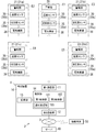
- FIG. 1 is a diagram illustrating configurations of a control system and an alarm system according to an aspect of the present disclosure.
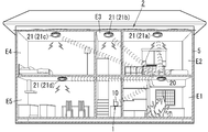
- FIG. 2 is a diagram illustrating an application example of the control system and the alarm system of the above.
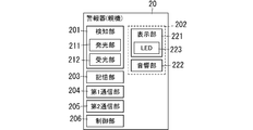
- FIG. 3 is a diagram showing a configuration of an alarm device as a master unit included in the alarm system of the above.
- FIG. 4 is a diagram showing a configuration of an alarm device as a child device included in the alarm system of the above.
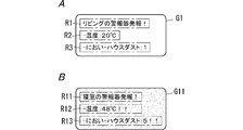
- FIG. 5A is a diagram illustrating a first alarm screen displayed by an information terminal which is a notification destination of the control system of the above.
- FIG. 5B is a diagram illustrating a second alarm screen displayed by the information terminal that is the notification destination of the control system.
- FIG. 6 is a diagram for explaining the operation of the alarm system of the above when a disaster occurrence is detected.
- control device 10 as the control system 1 according to the present embodiment and the alarm system 2 including the control device 10 will be described with reference to FIGS. 1 to 6.
- the alarm system 2 includes a control device 10 as the control system 1 according to the present embodiment, a plurality (five in the present embodiment) of alarm devices 20, 21, and a plurality of (the present embodiment). Then, five temperature sensors 30 and a plurality (five in this embodiment) of air quality sensors 35 are provided.
- the control device 10 as the control system 1 of the present embodiment is capable of communicating with a plurality of alarm devices (residential alarms) 20, 21 and a plurality of temperature sensors 30.
- alarm devices 21a, 21b, 21c, and 21d when distinguishing a plurality of (four in this embodiment) alarm devices 21, they are described as alarm devices 21a, 21b, 21c, and 21d.
- temperature sensors 30a, 30b, 30c, 30d, and 30e when distinguishing a plurality of air quality sensors 35, they are described as air quality sensors 35a, 35b, 35c, 35d, and 35e.
- the plurality of alarm devices 20 and 21 have a detection function of detecting the occurrence of a disaster in the facility 5 and an alarm function of notifying the occurrence of a disaster in the facility 5, and perform a notification operation regarding the disaster. ..
- the plurality of alarm devices 20 and 21 detect at least one of fire, water damage, and earthquake as a disaster.
- the plurality of alarm devices 20 and 21 perform a notification operation regarding fire. That is, the plurality of alarm devices 20 and 21 output sounds such as alarm sounds when a fire occurs.
- the target for issuing the alarm sound in the alarm devices 20 and 21 is not limited to the fire, and may be CO (carbon monoxide) generation due to gas leakage or incomplete combustion.
- a plurality of alarm devices 20 and 21 are provided in different spaces in the facility 5. Specifically, the plurality of alarm devices 20 and 21 are installed on a ceiling, a wall or the like in the installation target space. In the present embodiment, the plurality of alarm devices 20 and 21 are installed in the spaces E1 to E5 in the facility 5, respectively, as shown in FIG. Specifically, the alarm device 20 is installed in the space E1, the alarm device 21a is installed in the space E2, the alarm device 21b is installed in the space E3, the alarm device 21c is installed in the space E4, and the alarm device 21d is installed in the space E5 ( 1 and 2).
- a detached house is assumed as the facility 5.
- the facility 5 may be an apartment house (condominium).
- the facility 5 is not limited to a residence, but is a non-residential facility such as an office building, a theater, a movie theater, a public hall, a playground, a complex, a restaurant, a department store, a school, a hotel, an inn, a hospital, a nursing home, a kindergarten, It may be a library, a museum, an art gallery, an underground mall, a station, an airport, or the like.
- a communicable network is formed between the plurality of alarm devices 20 and 21.
- the alarm device 20 is used as a master device
- the plurality of alarm devices 21 are used as slave devices, and communication is possible between the master device and the slave devices.
- the plurality of alarm devices 20 and 21 are so-called interlocking type disaster prevention devices, and even if any of the alarm devices detects a fire, the alarm sounds in conjunction with other alarm devices (along with other alarm devices). Is configured to provide information.
- the alarm device (interlocking source) at the position of the fire origin issues, for example, an alarm sound "view view fire.”
- other alarm devices (interlocking destinations) issue an alarm sound that can identify the position of the fire origin.
- the alarm device 21a informs the alarm device 20, which is the parent device, of information indicating that the occurrence of the fire in the facility 5 is detected. It is transmitted as disaster occurrence information related to the occurrence detection.
- the alarm device 20 receives the detection result, the alarm device 20 issues an alarm sound and transmits an alarm instruction to the other slaves (alarm devices 21b to 21d). Further, the alarm device 20 transmits the detection result of the alarm device 21a to the control device 10.
- the alarm device 21 (alarm devices 21b to 21d) that has received the notification instruction from the alarm device 20 issues an alarm sound.
- the disaster occurrence information includes an identifier (alarm identifier) assigned to the alarm device of the transmission source.
- the alarm device 20 detects a fire, the alarm device 20 issues an alarm sound and sends an alarm instruction to the slaves (alarm devices 21a to 21d). Further, the alarm device 20 transmits the detection result of the alarm device 20 to the control device 10. The alarm device 21 (alarm devices 21a to 21d) that has received the notification instruction from the alarm device 20 issues an alarm sound.
- the plurality of temperature sensors 30 are respectively provided in the plurality of spaces E1 to E5 in which the plurality of alarm devices 20 and 21 are provided.
- the temperature sensor 30a is in the space E1
- the temperature sensor 30b is in the space E2
- the temperature sensor 30c is in the space E3
- the temperature sensor 30d is in the space E4
- the temperature sensor 30e is in the space E5,
- Each is provided (see FIG. 1).
- the temperature sensor 30 measures the temperature of the space (area) related to the facility 5. Specifically, the temperature sensor 30 measures the temperature of the space in which the temperature sensor 30 is installed.
- the plurality of air quality sensors 35 are respectively provided in the plurality of spaces E1 to E5 in which the plurality of alarm devices 20 and 21 are provided.
- the air quality sensor 35a is in the space E1
- the air quality sensor 35b is in the space E2
- the air quality sensor 35c is in the space E3
- the air quality sensor 35d is in the space E4
- the air quality sensor 35e is , Space E5, respectively (see FIG. 1).
- the air quality sensor 35 measures the air quality of the space (area) related to the facility 5. Specifically, the air quality sensor 35 measures the air quality of the space where the air quality sensor 35 is installed. For example, the air quality sensor 35 measures the amount of odor and house dust in the space to be measured, and uses the level of air pollution (air quality level) based on the measured amount of odor and house dust as the detection result.
- the control device 10 is configured to be able to wirelessly communicate with the alarm device 20 and each temperature sensor 30. Wireless communication using radio waves in the 920 MHz band is performed between the control device 10, the alarm device 20, and the temperature sensors 30. Further, as described above, communication is possible between the alarm device 20 and each alarm device 21. In the present embodiment, wireless communication using radio waves in the 420 MHz band is performed between the alarm device 20 and each alarm device 21. As a result, the control device 10 can communicate with each alarm device 21 via the alarm device 20.
- the frequency band used for communication between the control device 10 and the alarm device 20 and each temperature sensor 30 is not limited to the 920 MHz band, and may be appropriately changed according to the radio law or fire law of each country. It is a thing.
- the frequency band used for communication between the alarm device 20 and each alarm device 21 is not limited to the 420 MHz band, and can be appropriately changed according to the Radio Law or Fire Service Law of each country.
- the control device 10 acquires, as the disaster occurrence information from the alarm device 20 or the alarm device 21, the information indicating that the occurrence of the fire in the facility 5 is detected, the result (first state information) measured by the temperature sensor 30 and The result (second state information) measured by the air quality sensor 35 is acquired. Specifically, when the control device 10 obtains the detection result from at least one of the plurality of alarm devices 20 and 21, the control device 10 sets the temperature in the same space as the transmission source alarm device that transmitted the detection result.
- the first state information which is the result measured by the sensor 30, and the second state information, which is the result of the air quality measured by the air quality sensor 35 installed in the space, are acquired.
- the first state information includes the temperature detected by the temperature sensor 30.
- the second state information includes the air quality level (air quality level) detected by the air quality sensor 35.
- the control device 10 determines the probability of detection of a fire occurrence based on the acquired first state information and second state information.
- the control device 10 transmits, to the server 40 via the network 3, the alarm information according to the determination result and the information (for example, a telephone number) related to the information terminal to which the alarm information is notified.
- the information related to the information terminal will be referred to as notification destination information.
- the server 40 Upon receiving the alarm information and the notification destination information from the control device 10, the server 40 transmits the alarm information to the information terminal 50 based on the notification destination information. That is, the control device 10 notifies the information terminal 50 of the alarm information via the server 40.
- the alarm information according to the determination result for example, if it is determined that the probability of detecting a fire is low, the first alarm information indicating that a false alarm is likely to occur is high and the probability of detecting a fire is high.
- the control device 10 transmits the second alarm information which has a low possibility of false alarm.
- the first alarm information and the second alarm information include information related to different display modes.
- the information terminal 50 is a smartphone, a tablet terminal or the like owned by a person (for example, a resident) related to the facility 5.
- the information terminal 50 is assumed to be a smartphone.
- the information terminal 50 acquires the alarm information via the network 3.
- the information terminal 50 displays a message indicating that at least the occurrence of a fire in the facility 5 is detected based on the alarm information.
- the first alarm information and the second alarm information include information related to different display modes.
- the information terminal 50 displays these messages such that the display mode of these messages differs depending on whether the messages are displayed based on the first alarm information or the second alarm information. indicate.
- the control device 10 is, for example, a controller of a HEMS (home energy management system), and can communicate with a plurality of devices provided in the facility 5.
- the plurality of devices include the temperature sensor 30 and the air quality sensor 35 described above.
- the control device 10 can further communicate with a plurality of alarm devices 20 and 21 provided in the facility 5.
- the control device 10 can also communicate with the electric device 38 (see FIG. 1) provided in the facility 5.
- the control device 10 includes a first communication unit 11, a second communication unit 12, a storage unit 13, and a control unit 14.
- the control device 10 has, for example, a computer system having a processor and a memory. Then, the computer system functions as the control unit 14 by the processor executing the program stored in the memory.
- the program executed by the processor is recorded in advance in the memory of the computer system here, but may be recorded in a non-transitory recording medium such as a memory card and provided, or provided through an electric communication line such as the Internet. May be.
- the first communication unit 11 includes a communication interface for communicating with the alarm device 20, each temperature sensor 30, each air quality sensor 35, and each electric device 38.
- the first communication unit 11 receives the detection result of the alarm device 20 and the detection result of each alarm device 21 from the alarm device 20 by wireless communication using radio waves in the 920 MHz band. Furthermore, the first communication unit 11 uses wireless communication using radio waves in the 920 MHz band to obtain the first state information that is the result of measurement by the temperature sensor 30 and the second state information that is the result of air quality measured by the air quality sensor 35. Receive status information.
- the first communication unit 11 receives the information related to the electric device by wireless communication using a radio wave in the 920 MHz band.
- the second communication unit 12 has a communication interface for communicating with the server 40 via the network 3 such as the Internet.
- the storage unit 13 is composed of a device selected from ROM (Read Only Memory), RAM (Random Access Memory), EEPROM (Electrically Erasable Programmable Read Only Memory), and the like.
- the storage unit 13 stores the alarm device identifiers of the alarm devices 20 and 21, the temperature sensor identifiers of the temperature sensors 30, and the air quality sensor identifiers of the air quality sensors 35. There is. Specifically, the storage unit 13 stores, for each of the spaces E1 to E5, an alarm device identifier of the alarm device 20 (or 21) provided in the space, a temperature sensor identifier of the temperature sensor 30, and an air quality sensor 35. The air quality sensor identifier is stored in association with. For example, the storage unit 13 stores the alarm device identifier of the alarm device 20, the temperature sensor identifier of the temperature sensor 30a, and the air quality sensor identifier of the air quality sensor 35a in the space E1 in association with each other.
- the storage unit 13 stores the alarm device identifier of the alarm device 21a, the temperature sensor identifier of the temperature sensor 30b, and the air quality sensor identifier of the air quality sensor 35b in the space E2 in association with each other.
- the storage unit 13 stores the alarm device identifier of the alarm device 21b, the temperature sensor identifier of the temperature sensor 30c, and the air quality sensor identifier of the air quality sensor 35c in the space E3 in association with each other.
- the storage unit 13 stores the alarm device identifier of the alarm device 21c, the temperature sensor identifier of the temperature sensor 30d, and the air quality sensor identifier of the air quality sensor 35d in the space E4 in association with each other.
- the storage unit 13 stores the alarm device identifier of the alarm device 21d, the temperature sensor identifier of the temperature sensor 30e, and the air quality sensor identifier of the air quality sensor 35e in the space E5 in association with each other.
- the alarm device identifier is a device unique ID in which the model number and the manufacturing serial number of the corresponding alarm device 20 (or 21) are combined, a Mac address, or the like.
- the temperature sensor identifier is a device unique ID in which the model number and the manufacturing serial number of the corresponding temperature sensor 30 are combined, or a Mac address or the like.
- the air quality sensor identifier is a device unique ID in which the model number and manufacturing serial number of the corresponding air quality sensor 35 are combined, or a Mac address or the like.
- the control unit 14 includes a first acquisition unit 101, a second acquisition unit 102, and a notification processing unit 103, as shown in FIG.
- the first acquisition unit 101 acquires disaster occurrence information from the alarm device 20 (or 21). Specifically, when the alarm device 20 detects the occurrence of a fire, the first acquisition unit 101 acquires the disaster occurrence information of the alarm device 20 via the first communication unit 11. When the alarm device 21 detects the fire occurrence, the first acquisition unit 101 uses the information indicating that the fire occurrence is detected in the facility 5 via the first communication unit 11 as the disaster occurrence information. Get from 20.
- the second acquisition unit 102 When the second acquisition unit 102 acquires, as the disaster occurrence information, the information indicating that the first acquisition unit 101 has detected the occurrence of the disaster, the second acquisition unit 102 outputs the first state information of the temperature sensor 30 from the temperature sensor 30 to the air quality sensor.
- the second state information of 35 is acquired from the air quality sensor 35, respectively.
- the second acquisition unit 102 when the alarm device 20 detects the occurrence of a fire, the second acquisition unit 102 outputs the first state information of the temperature sensor 30a in the space E1 in which the alarm device 20 that is the transmission source of the disaster occurrence information is provided. , And acquires the second state information of the air quality sensor 35a via the first communication unit 11, respectively.
- the second acquisition unit 102 is a temperature sensor in the space (for example, the space E2) where the alarm device 21 that is the transmission source of the detection result is provided.
- the first state information of 30 for example, the temperature sensor 30b
- the second state information of the air quality sensor 35b are acquired via the first communication unit 11, respectively.
- the second acquisition unit 102 sets an alarm device identifier that matches the alarm device identifier included in the disaster occurrence information acquired by the first acquisition unit 101 among the plurality of alarm device identifiers stored in the storage unit 13.
- the associated temperature sensor identifier and air quality sensor identifier are obtained from the storage unit 13.
- the second acquisition unit 102 transmits, via the first communication unit 11, first request information requesting the first state information to the temperature sensor 30 having the acquired temperature sensor identifier.
- the second acquisition unit 102 acquires the first state information from the temperature sensor 30 that has received the first request information, via the first communication unit 11.
- the second acquisition unit 102 transmits, via the first communication unit 11, second request information requesting the second state information to the air quality sensor 35 having the acquired air quality sensor identifier.
- the second acquisition unit 102 acquires the second state information from the air quality sensor 35 that has received the second request information, via the first communication unit 11.
- the notification processing unit 103 identifies a space in which a fire has been detected from among the spaces E1 to E5 based on the alarm identifier included in the disaster occurrence information acquired by the first acquisition unit 101. Specifically, the notification processing unit 103 specifies the space corresponding to the alarm device identifier that matches the alarm device identifier included in the disaster occurrence information among the plurality of alarm device identifiers stored in the storage unit 13. For example, when the alarm device identifier included in the disaster occurrence information is the identifier assigned to the alarm device 20, the notification processing unit 103 identifies the space E1 in which the fire has been detected.
- the notification processing unit 103 determines the likelihood of detecting a fire occurrence in the alarm device 20 (or 21) based on the acquired first state information and second state information.
- the notification processing unit 103 determines whether or not the temperature included in the first state information satisfies a condition that the temperature is lower than a first reference temperature that is a predetermined first temperature determination condition (first determination condition). .. In short, the notification processing unit 103 determines whether the temperature included in the first state information is lower than the first reference temperature.
- the notification processing unit 103 determines whether the air quality level included in the second state information is lower than the first reference level.
- the notification processing unit 103 When both the first temperature determination condition and the first air quality determination condition are satisfied, the notification processing unit 103 outputs the first alarm information indicating that there is a high possibility of false alarm via the server 40 to the information terminal. Send to 50.
- the notification processing unit 103 includes a message indicating that a fire has been detected, a detection location (a space where a fire has been detected), first state information, second state information, and a background color of the message.
- the first alarm information including the (first background color) is transmitted to the information terminal 50 via the server 40.
- the notification processing unit 103 determines whether or not the temperature included in the first state information is equal to or higher than the second reference temperature.
- the second reference temperature is equal to or higher than the first reference temperature.
- the first reference temperature and the second reference temperature are the same. That is, when the temperature included in the first state information does not satisfy the first temperature determination condition, the second temperature determination condition is satisfied.
- the notification processing unit 103 determines whether the air quality level included in the second state information is lower than the second reference level.
- the second reference level is equal to or higher than the first reference level.
- the first reference level and the second reference level are the same. That is, when the air quality level included in the second state information does not satisfy the first air quality determination condition, the second air quality determination condition is satisfied.
- the notification processing unit 103 indicates that the possibility of false alarm is low (the probability of detection of fire occurrence is high) when at least one of the second temperature determination condition and the second air quality determination condition is satisfied. 2
- the alarm information is transmitted to the information terminal 50 via the server 40.
- the notification processing unit 103 includes a message indicating that a fire has been detected, a detection location, first state information, second state information, and a second background color different from the first background color. 2
- the alarm information is transmitted to the information terminal 50 via the server 40.
- the notification processing unit 103 makes the first background color included in the first alarm information different from the second background color included in the second alarm information. That is, the notification processing unit 103 changes the notification mode (display mode) according to the determination result of the probability of fire occurrence.
- the alarm device 20 has a detection function to detect the occurrence of a disaster (here, a fire) in the facility 5, and an alarm function to notify when the occurrence of the disaster in the facility 5 is detected.
- the alarm device 20 includes a detection unit 201, a notification unit 202, a storage unit 203, a first communication unit 204, a second communication unit 205, and a control unit 206.
- the alarm device 20 has a battery (for example, a lithium battery), and operates by the electric power supplied from the battery.
- the alarm device 20 has, for example, a computer system having a processor and a memory. Then, the computer system functions as the control unit 206 by the processor executing the program stored in the memory.
- the program executed by the processor is recorded in advance in the memory of the computer system here, but may be recorded in a non-transitory recording medium such as a memory card and provided, or provided through an electric communication line such as the Internet. May be.
- the detection unit 201 has a function (detection function) of detecting information about a fire that is a target for issuing an alarm sound.
- the detection unit 201 is, for example, a photoelectric sensor that detects smoke. Therefore, the said information contains the information regarding smoke, for example.
- the detection unit 201 includes, for example, a light emitting unit 211 such as an LED and a light receiving unit 212 such as a photodiode.
- the light emitting unit 211 and the light receiving unit 212 are arranged so that the light receiving surface of the light receiving unit 212 deviates from the optical axis of the irradiation light of the light emitting unit 211 in the labyrinth of the housing of the own device. In the event of a fire, smoke may be introduced into the labyrinth through holes provided in the housing.
- the light emitted from the light emitting unit 211 hardly reaches the light receiving surface of the light receiving unit 212.
- the irradiation light of the light emitting unit 211 is scattered by the smoke, and a part of the scattered light reaches the light receiving surface of the light receiving unit 212. That is, in the detection unit 201, the light receiving unit 212 receives the irradiation light of the light emitting unit 211 scattered by the smoke.
- the detection unit 201 outputs an electric signal (detection signal) indicating a voltage level according to the amount of light received by the light receiving unit 212 to the control unit 206.
- the notification unit 202 has a display unit 221 and a sound unit 222.
- the notification unit 202 has a function (notification function) of notifying the occurrence of a fire when detecting the occurrence of a disaster in the facility 5.
- the notification unit 202 performs notification by light and sound.
- the sound section 222 has a function of reporting the occurrence of a fire.
- the acoustic section 222 outputs a sound (sound wave).
- the control unit 206 determines that a fire has occurred, the sound unit 222 outputs an alarm sound to notify the occurrence of the fire.
- the sound unit 222 is composed of a speaker that converts an electric signal into sound.
- the speaker has a diaphragm, and emits an alarm sound by mechanically vibrating the diaphragm according to an electric signal.
- the sound unit 222 outputs an alarm sound (for example, a “beep” sound) under the control of the control unit 206.
- the sound unit 222 preferably changes the loudness (sound pressure level) of the warning sound and outputs the warning sound.
- the alarm sound may include, for example, a sweep sound that is swept from a low sound to a high sound.
- the alarm sound may include, for example, a voice message such as "It's a fire. It's a fire.”
- the warning sound may be composed of a sweep sound and a voice message following the sweep sound.
- the acoustic unit 222 stops outputting the alarm sound.
- the display unit 221 has a function of notifying the occurrence of fire.
- the display unit 221 has a red LED (Light Emitting Diode) 223 as a light source.
- the display unit 221 is normally turned off (when monitoring a fire), and starts blinking (or lighting) when the control unit 206 determines that a fire has occurred.
- the blinking for notifying the occurrence of a fire may be referred to as "operation blinking".
- the operation blinking is stopped under the control of the control unit 206 when the alarm sound is stopped.
- the storage unit 203 is composed of a device selected from ROM, RAM, EEPROM, or the like.
- the storage unit 203 stores alarm message data relating to a voice message output as an alarm sound.
- the storage unit 203 also stores transmission message data to be transmitted to the information terminal as notification information. Further, the storage unit 203 stores an alarm device identifier assigned to itself.
- the first communication unit 204 has a communication interface for wirelessly communicating with the alarm device 21, which is a child device.
- the first communication unit 204 communicates with the alarm device 21 by wireless communication using radio waves in the 420 MHz band.
- the first communication unit 204 receives the detection result of the alarm device 21. Further, when the first communication unit 204 receives the detection result from one alarm device 21 (for example, the alarm device 21a), the first communication unit 204 transmits a warning instruction to the other alarm devices 21 (alarm devices 21b to 21d).
- the second communication unit 205 has a communication interface for wirelessly communicating with the control device 10.
- the second communication unit 205 communicates with the control device 10 by wireless communication using radio waves in the 920 MHz band.
- the second communication unit 205 detects a fire, the second communication unit 205 transmits the detection result of the own device to the control device 10.
- the first communication unit 204 receives the detection result of the alarm device 21, the second communication unit 205 transmits the detection result of the alarm device 21 to the control device 10.
- the control unit 206 determines whether a fire has occurred based on the detection signal output by the detection unit 201. For example, the control unit 206 determines that a fire has occurred when the voltage level indicated by the detection signal is equal to or higher than a predetermined threshold value.
- the control unit 206 determines that a fire has occurred, the control unit 206 is information indicating the detection of a disaster, in other words, information indicating that the occurrence of a fire at the facility 5 is detected, and includes the alarm device identifier of the own device.
- the disaster occurrence information is transmitted to the control device 10 via the second communication unit 205.
- the control unit 206 determines that a fire has occurred, the control unit 206 transmits a notification instruction to each of the alarm devices 21 that are child devices via the first communication unit 204.
- the control unit 206 determines that a fire has occurred, the control unit 206 causes the sound unit 222 to start outputting an alarm sound. For example, when outputting a voice message as an alarm sound from the sound unit 222, the control unit 206 generates a voice signal corresponding to the voice message based on the message data stored in the storage unit 203. At this time, the acoustic unit 222 outputs a voice message (alarm sound) based on the voice signal generated by the control unit 206.
- control unit 206 determines that a fire has occurred, the control unit 206 controls the display unit 221 to blink the display unit 221.
- the control unit 206 Upon acquiring the disaster occurrence information from the alarm device 21 via the first communication unit 204, the control unit 206 sends the disaster occurrence information sent from the alarm device 21 to the control device 10 via the second communication unit 205. .. Further, the control unit 206 transmits a notification instruction to the other alarm device 21, which is a child device, via the first communication unit 204.
- control unit 206 When the control unit 206 receives, as a detection result, information indicating that a fire in the facility 5 is detected from the alarm device 21, the control unit 206 starts outputting an alarm sound from the sound unit 222. Further, the control unit 206 controls the display unit 221 so that the display unit 221 blinks.
- (2-3) Alarm device (child device)
- the configuration of the alarm device 21, which is a child device will be described.
- the same components as those of the alarm device 20 are designated by the same reference numerals as those of the alarm device 20, and the description thereof will be omitted as appropriate.
- the alarm device 21 has a detection function of detecting the occurrence of a disaster (here, a fire) in the facility 5, and an alarm function of notifying when the occurrence of the disaster in the facility 5 is detected. ..
- the alarm device 21 has a detection unit 201, a notification unit 202, a storage unit 203, a communication unit 250, and a control unit 251.
- the alarm device 21 has a battery (for example, a lithium battery), and operates by the electric power supplied from the battery.
- the alarm device 21 has, for example, a computer system having a processor and a memory.
- the computer system functions as the control unit 251 when the processor executes the program stored in the memory.
- the program executed by the processor is recorded in advance in the memory of the computer system here, but may be recorded in a non-transitory recording medium such as a memory card and provided, or provided through an electric communication line such as the Internet. May be.
- the communication unit 250 has a communication interface for wirelessly communicating with the alarm device 20, which is the master device.
- the communication unit 250 communicates with the alarm device 20 by wireless communication using radio waves in the 420 MHz band.
- the communication unit 250 transmits the detection result of the alarm device 21. Further, the communication unit 250 receives the notification instruction from the alarm device 20.
- the control unit 251 determines whether or not a fire has occurred, based on the detection signal output by the detection unit 201 of the own device. For example, the control unit 251 determines that a fire has occurred when the voltage level indicated by the detection signal is equal to or higher than a predetermined threshold value.
- the control unit 251 determines that a fire has occurred, the control unit 251 is information indicating that a disaster has been detected, in other words, information that indicates that a fire at the facility 5 has been detected, and the disaster occurrence information includes the identifier for the alarm device of the own device. Is transmitted to the alarm device 20 via the communication unit 250.
- the control unit 251 determines that a fire has occurred, the control unit 251 causes the sound unit 222 of its own machine to start outputting an alarm sound. For example, when the control unit 251 outputs a voice message as an alarm sound from the sound unit 222 of the own device, the control unit 251 outputs a voice signal corresponding to the voice message based on the message data stored in the storage unit 203 of the own device. To generate. At this time, the acoustic unit 222 outputs a voice message (alarm sound) based on the voice signal generated by the control unit 251.
- control unit 251 determines that a fire has occurred, the control unit 251 controls the display unit 221 of the own device so as to blink the display unit 221 of the own device.
- control unit 251 When the control unit 251 receives a notification instruction from the alarm device 20 via the communication unit 250, the control unit 251 starts outputting an alarm sound from the sound unit 222 of the own device. Further, the control unit 251 controls the display unit 221 of the own device so that the display unit 221 of the own device blinks.
- the temperature sensor 30 is, for example, a contact type temperature sensor, and detects the temperature in the space where the own device is installed.
- the temperature sensor 30 has a communication interface for wirelessly communicating with the control device 10. Specifically, the temperature sensor 30 communicates with the control device 10 by wireless communication using radio waves in the 920 MHz band.
- the temperature sensor 30 constantly measures the temperature and stores the measurement result (measured temperature). When the temperature sensor 30 receives the first request information from the control device 10, the temperature sensor 30 transmits the first state information including the temperature measured at the time when the first request information is received, to the control device 10.
- the air quality sensor 35 of this embodiment measures the amount of odor and house dust in the space to be measured.
- the air quality sensor 35 is an air purifier that includes an odor sensor and a dust sensor (floating particle measuring instrument) that measures the amount of house dust.
- the odor sensor is composed of a semiconductor type sensor, a crystal vibration type sensor, etc.
- the odor sensor converts the detected odor (odor) into an odor level indicating the degree of odor, and uses the conversion result as a measurement result.
- the dust sensor measures the amount of particles (pollen, house dust, smoke, etc.) floating in the atmosphere and converts it into the concentration (air pollution level).
- the dust sensor uses the converted concentration (air contamination level) as the measurement result.
- the air quality sensor 35 has a communication interface for wirelessly communicating with the control device 10. Specifically, the air quality sensor 35 communicates with the control device 10 by wireless communication using radio waves in the 920 MHz band.
- the air quality sensor 35 constantly measures odor and house dust, and stores the measurement result (measured odor level and air pollution level).
- the air quality sensor 35 controls the second state information including the higher level of the odor level and the air pollution level measured at the time when the second request information is received. Transmit to device 10.
- the air quality sensor 35 is configured to include the higher level of the odor level and the air pollution level in the second state information, but the configuration is not limited to this.
- the air quality sensor 35 may include the average level of the odor level and the air pollution level in the second state information, or may include the lower one of the odor level and the air pollution level in the second state information. ..
- the server 40 has a computer system having a processor and a memory, for example. Then, the computer system functions as the server 40 by the processor executing the program stored in the memory.
- the program executed by the processor is recorded in advance in the memory of the computer system here, but it may be recorded in a non-transitory recording medium such as a memory card and provided, or provided through an electric communication line such as the Internet. May be.
- the server 40 is configured to be able to communicate with the control device 10 and the information terminal 50.
- the server 40 receives the alarm information which is either the first alarm information or the second alarm information and the notification destination of the alarm information from the control device 10, the server 40 transmits the alarm information to the information terminal 50 which is the notification destination.
- the information terminal 50 has, for example, a computer system having a processor and a memory. Then, the computer system functions as the information terminal 50 by the processor executing the program stored in the memory.
- the program executed by the processor is recorded in advance in the memory of the computer system here, but it may be recorded in a non-transitory recording medium such as a memory card and provided, or provided through an electric communication line such as the Internet. May be.
- the information terminal 50 is configured to be able to communicate with the server 40.
- the information terminal 50 receives the alarm information, which is either the first alarm information or the second alarm information transmitted by the control device 10, via the server 40.
- the information terminal 50 displays a message indicating that a fire has been detected on the display unit included in the information terminal 50 in the specified display mode based on the information included in the received alarm information.
- the display unit of the information terminal 50 has a touch panel function.
- the screen displayed on the information terminal 50 will be described below.
- FIG. 5A shows an example of the first alarm screen G1 based on the first alarm information.
- the first alarm screen G1 includes a first display area R1, a second display area R2, and a third display area R3.
- a message indicating that the occurrence of fire has been detected is displayed.
- FIG. 5A “A living room alarm is issued!” is displayed as a message that a fire has been detected in the living room.
- a message notifying the temperature included in the first state information is displayed.
- a message notifying the air quality level included in the second state information is displayed.
- the background color of the first alarm screen G1 is a color designated by the first background color (for example, white).
- FIG. 5B shows an example of the second alarm screen G11 based on the second alarm information.
- the second alarm screen G11 includes a first display area R11, a second display area R12, and a third display area R13.
- a message indicating that a fire has been detected is displayed in the first display area R11.
- FIG. 5B “Bedroom alarm is issued!” is displayed as a message that a fire has been detected in the bedroom.
- a message notifying the temperature included in the first state information is displayed in the second display area R12.
- a message notifying the air quality level included in the second state information is displayed.
- the background color of the second alarm screen G11 is the color designated by the second background color (for example, red).
- the user of the information terminal 50 can judge the probability of detection of a fire occurrence (whether or not the alarm is a false alarm) by the background color of the displayed alarm screen.
- the first status information and the second status information are displayed, it is possible to judge the probability of detection of a fire occurrence (whether or not the alarm is a false alarm) based on these display contents. For example, when a fire occurs, the temperature of the place of occurrence rises and smoke is also generated, so that the level of air pollution also rises. Therefore, for example, when the measurement result of the temperature sensor 30 in the space where the fire is detected indicates that the temperature of the space is high and the measurement result of the air quality sensor 35 indicates that the air is heavily contaminated, The user can determine that the probability of detecting the occurrence is high.
- the measurement result of the temperature sensor 30 in the space where the fire is detected indicates that the temperature of the space is low, and the measurement result of the air quality sensor 35 indicates that the air is not badly contaminated.
- the user can determine that the probability of detecting a fire is low (which is often a false alarm).
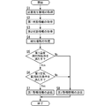
- the first acquisition unit 101 of the control device 10 acquires the disaster occurrence information of the alarm device 20 (or 21) (step S1).
- the second acquisition unit 102 of the control device 10 acquires the first state information of the temperature sensor 30 in the space provided with the alarm device 20 (or 21) that is the transmission source of the disaster occurrence information (step S2).
- the second acquisition unit 102 acquires the second state information of the air quality sensor 35 in the space (step S3).
- the notification processing unit 103 identifies the space (detection place) where the fire is detected based on the alarm identifier included in the disaster occurrence information (step S4).
- the notification processing unit 103 determines whether the first state information satisfies the first temperature determination condition (step S5). For example, the notification processing unit 103 determines whether the temperature included in the first state information is lower than the first reference temperature.
- the notification processing unit 103 determines whether the two-state information satisfies the first air quality determination condition (step S6). For example, the notification processing unit 103 determines whether the air quality level included in the first state information is lower than the first reference level.
- the notification processing unit 103 When it is determined that the second state information satisfies the first air quality determination condition, that is, the air quality level included in the second state information is lower than the first reference level (“Yes” in step S6), the notification processing unit 103. Transmits the first alarm information to the information terminal 50 via the server 40 (step S7).
- the notification processing unit 103 When determining that the first state information does not satisfy the first temperature determination condition, that is, the temperature included in the first state information is equal to or higher than the first reference temperature (“No” in step S5), the notification processing unit 103 , The second alarm information is transmitted to the information terminal 50 via the server 40 (step S8).
- the notification process When it is determined that the second state information does not satisfy the first air quality determination condition, that is, the air quality level included in the second state information is equal to or higher than the first reference level (“No” in step S6), the notification process The unit 103 transmits the second alarm information to the information terminal 50 via the server 40 (step S8).
- the notification processing unit 103 changes the background color of the alarm screen displayed on the information terminal 50 according to the determination result of the probability of detecting the fire occurrence. There is. Thereby, the user of the information terminal 50 can determine the certainty of detection of a fire occurrence (whether or not the alarm is a false alarm) based on the background color of the displayed alarm screen.
- the user can judge the probability of detection of fire occurrence (whether or not the alarm is a false alarm) based on these display contents. it can. For example, when a fire occurs, the temperature of the place of occurrence rises and smoke is also generated, so that the level of air pollution also rises. Therefore, for example, when the measurement result of the temperature sensor 30 in the space where the fire is detected indicates that the temperature of the space is high and the measurement result of the air quality sensor 35 indicates that the air is heavily contaminated, The user can determine that the probability of detecting the occurrence is high.
- the measurement result of the temperature sensor 30 in the space where the fire is detected indicates that the temperature of the space is low, and the measurement result of the air quality sensor 35 indicates that the air is not badly contaminated.
- the user can determine that the probability of detecting a fire is low (the possibility of false alarm is high).
- the resident of the facility 5 can know that a fire has been detected and the certainty of the detection.
- the first alarm information includes the first state information and the second state information, and the first background color
- the second alarm information is the first state information and the second state information, and the second background.
- the configuration including the color is adopted, the configuration is not limited to this.
- the first alarm information and the second alarm information may not include the first status information and the second status information.
- the first alarm information may not include the first background color and the second alarm information may not include the second background color. That is, the first alarm information report includes at least one of the first state information and the second state information and the background color, and the second alarm information report includes the first state information and the second state information and the background color. At least one of them should be included.
- the notification processing unit 103 when the notification processing unit 103 transmits the first warning information and the second warning information, the notification processing unit 103 includes the first status information and the second status information in the warning information that is the notification target, and notifies the first warning.
- the configuration may be such that at least one of changing the display mode of information and the notification mode of the second warning information is changed.
- the first alarm information and the second alarm information are configured to include both the first state information and the second state information, but the configuration is not limited to this.
- the first alarm information and the second alarm information may include any one of the first status information and the second status information.
- the alarm system 2 includes a plurality of temperature sensors 30 and a plurality of air quality sensors 35.
- the alarm system 2 may be configured to include any one of the plurality of temperature sensors 30 and the plurality of air quality sensors 35.
- control device 10 uses the measurement results of the temperature sensor 30 and the air quality sensor 35 in the space where the fire is detected, and determines the reliability of the detection of the fire. It is not limited to the configuration.
- the control device 10 may determine the certainty of detecting the fire occurrence by using the operating state of the electric device 38 provided in the space where the fire occurrence is detected.
- the electric device 38 is, for example, an electric stove, an electric carpet, or the like, and can communicate with the control device 10.
- the second acquisition unit 102 of the control device 10 acquires the operation information indicating the operation state of the electric device 38 from the electric device 38 in the space where the occurrence of the fire is detected.
- the notification processing unit 103 determines that the probability of detecting a fire occurrence is high.
- the notification processing unit 103 determines that the probability of detecting a fire is low.
- the first alarm information and the second alarm information may include operation information.
- the information terminal 50 may display the operating state represented by the operating information when displaying the first alarm screen G1 based on the first alarm information. For example, when the electric device 38 is an electric carpet, a message indicating that the electric carpet is not operating is displayed.
- the information terminal 50 may display the operating state represented by the operating information when displaying the second alarm screen G11 based on the second alarm information. For example, when the electric device 38 is an electric carpet, a message indicating that the electric carpet is in operation is displayed.
- the notification processing unit 103 may determine the certainty of detecting a fire by combining the movable state of the electric device 38 and at least one of the first state information and the second state information. For example, when combining the movable state of the electric device 38 with both the first state information and the second state information, the notification processing unit 103 determines that the electric device is inactive, the first temperature determination. When all the conditions and the first air quality determination condition are satisfied, the first alarm information is transmitted to the information terminal 50, and otherwise the second alarm information is transmitted to the information terminal 50.
- the first alarm information and the second alarm information are temperature history information indicating the transition of the measurement result of the temperature sensor 30 (transition of the state) and air quality history information indicating the transition of the measurement result of the air quality sensor 35 (transition of the state). You may include at least one of these. Here, it is assumed that both the temperature history information and the air quality history information are included in the first alarm information and the second alarm information.
- the temperature sensor 30 in the space where the occurrence of the fire is detected acquires temperature groups of a plurality of temperatures measured in the past 3 minutes from the time when the first request information is received.
- the temperature sensor 30 transmits, to the control device 10, the first state information including the temperature measured at the time when the first request information is received (detection temperature) and the acquired temperature group.
- the air quality sensor 35 in the space in which the occurrence of the fire is detected acquires a level group of a plurality of air quality levels measured in the past 3 minutes from the time when the second request information is received.
- the air quality sensor 35 transmits the second state information including the air quality level (detection level) measured at the time when the second request information is received and the acquired level group to the control device 10.
- the second acquisition unit 102 of the control device 10 receives the first state information including the detection time temperature and the temperature group from the temperature sensor 30, and the second state information including the detection time level and the level group from the air quality sensor 35. Get each.
- the notification processing unit 103 of the control device 10 When transmitting the first alarm information, the notification processing unit 103 of the control device 10 sends the first state information including the detection time temperature and the temperature group and the second state information including the detection time level and the level group, It is included in the first alarm information and transmitted. Similarly, when transmitting the second alarm information, the notification processing unit 103 sets the first state information including the detection time temperature and the temperature group and the second state information including the detection time level and the level group to the second state information. 1 Include in alarm information and send.
- the temperatures of the temperature groups included in the first state information and the air quality levels of the level groups included in the second state information are displayed in chronological order. They may be displayed side by side. Alternatively, on the first alarm screen G1, each temperature of the temperature group included in the first state information and each air quality level of the level group included in the second state information may be displayed as a graph.
- each temperature of the temperature group included in the first state information and each air quality level of the level group included in the second state information are displayed. You may display it side by side along a series. Alternatively, on the second alarm screen G11, each temperature of the temperature group included in the first state information and each air quality level of the level group included in the second state information may be displayed as a graph.
- each temperature of the temperature group included in the first state information and each air quality level of the level group included in the second state information are displayed on a screen different from the first alarm screen G1 and the second alarm screen G11. You may.
- a predetermined operation for example, a touch operation
- the second display area R2 in which the temperature (temperature at detection) included in the first state information is displayed.
- a screen in which the temperatures of the temperature group are arranged in time series may be displayed instead of the first alarm screen G1.
- a screen in which each temperature of the temperature group is graphed may be displayed.
- a predetermined operation for example, a touch operation
- the air quality level detection level
- a screen in which the air quality levels of the level group are arranged in time series may be displayed instead of the first alarm screen G1.
- a screen in which each air quality level of the level group is graphed may be displayed.
- the notification processing unit 103 may transit to a screen including further detailed information and display the screen. In other words, the notification processing unit 103 may cause the information terminal 50 to display a hierarchy.
- the alarm device 20 (or 21) and the control device 10 may be integrated devices.
- control unit 206 includes the functions of the control unit 14 (the first acquisition unit 101, the second acquisition unit 102, and the notification processing unit 103).
- the first acquisition unit 101 of the control unit 206 acquires the detection signal from the detection unit 201 as disaster occurrence information related to detection of fire occurrence in the facility 5.
- the notification processing unit 103 of the control unit 206 determines whether or not the detection signal (disaster occurrence information) acquired by the first acquisition unit 101 indicates that the occurrence of a disaster has been detected. Specifically, when the voltage level indicated by the detection signal is equal to or higher than a predetermined threshold, the notification processing unit 103 determines that the disaster occurrence information, which is the detection signal, indicates that the occurrence of a disaster is detected. To do.
- the notification processing unit 103 determines that the disaster occurrence information indicates that a disaster occurrence has been detected, the notification processing unit 103 instructs the second acquisition unit 102 to acquire the first state information and the second state information.
- the notification processing unit 103 uses the first state information and the second state information acquired by the second acquisition unit 102 to determine the probability of detecting a fire occurrence.
- the notification processing unit 103 transmits one of the first alarm information and the second alarm information to the information terminal 50 via the server 40 according to the determination result.
- control device 10 has a configuration in which the probability of detecting a fire occurrence is determined to be one of two types, that is, a low level of reliability and a high level of reliability.
- the configuration is not limited to this.
- control device 10 may determine which of a plurality of levels the probability of detection of a fire belongs to. Specifically, the control device 10 may determine which of the three levels (levels 1 to 3) the probability of detection of a fire occurrence belongs to.
- control device 10 stores different first reference temperatures and second reference temperatures.
- the control device 10 stores a first reference level and a second reference level that are different from each other.
- the notification processing unit 103 When the temperature included in the first state information is lower than the first reference temperature and the air quality level included in the second state information is lower than the first reference level, the notification processing unit 103 outputs the first alarm information, The information is transmitted to the information terminal 50.
- the notification processing unit 103 Second alarm information is transmitted to the information terminal 50.
- the notification processing unit 103 determines that the temperature included in the first state information is lower than the second reference temperature and the air quality level included in the second state information is lower than the second reference level that is equal to or higher than the first reference level.
- the second alarm information is transmitted to the information terminal 50.
- the notification processing unit 103 If the temperature included in the first state information is equal to or higher than the second reference temperature or the air quality level included in the second state information is equal to or higher than the second reference level, the notification processing unit 103 outputs the third alarm information. Is transmitted to the information terminal 50.
- the third alarm information is a third background color different from both the first background color and the second background color, a message indicating that a fire has been detected, a detection location, and first state information. And second state information.
- the alarm devices 20 and 21 are configured to have both a detection function and a notification function, but the configuration is not limited to this.
- the alarm devices 20 and 21 may be configured to have only a detection function.
- control device 10 is configured as a HEMS controller as an example, but the configuration is not limited to this.
- the control device 10 may be any device that can be connected to the network 3.
- the alarm device 20 is used as a master device
- the alarm device 21 is used as a slave device
- the slave device is configured to communicate with the control device via the master device, but the configuration is not limited to this.
- the alarm device 21 may be configured to communicate with the control device 10 without using another alarm device (alarm device 20).
- the alarm system 2 has a configuration including the plurality of alarm devices 20 and 21, but the configuration is not limited to this.
- the alarm system 2 may include only one alarm that can communicate with the control device 10.
- the alarm device only needs to include at least one alarm device capable of communicating with the control device 10.
- the control device 10 described in the above embodiment may be applied to an apartment house.
- the control device 10 is provided in each dwelling unit (corresponding to the facility 5) of the housing complex.
- the control device 10 is provided in the manager's room of the housing complex in addition to transmitting the alarm information corresponding to the determination result among the first alarm information and the second alarm information to the information terminal 50 via the server 40. It may be transmitted to the management device.
- the alarm device 21 may have the same configuration as the alarm device 20.
- the installer selects one alarm device from the alarm devices 20 and 21, and uses the selected one alarm device as a master device and the remaining alarm devices. Set as a slave.
- the first communication unit 11 may communicate with the alarm device 20, each temperature sensor 30, and each air quality sensor 35 by wire.
- control device 10 is configured to communicate with the information terminal 50 via the server 40, but the configuration is not limited to this.
- the control device 10 may communicate with the information terminal 50 without going through the server 40.
- control device 10 is configured to transmit the first alarm information when both the first temperature determination condition and the first air quality determination condition are satisfied, but the configuration is not limited to this. ..
- the notification processing unit 103 of the control device 10 may transmit the first alarm information when one of the first temperature determination condition and the first air quality determination condition is satisfied. In this case, the notification processing unit 103 transmits the second alarm information when both the first temperature determination condition and the first air quality determination condition are not satisfied.
- control system 1 may be embodied by a control method, a computer program, a recording medium recording the program, or the like.
- the control method of the control system 1 includes a first acquisition step, a second acquisition step, and a notification processing step.
- the first acquisition step acquires disaster occurrence information related to detection of a disaster occurrence in a disaster detector (for example, the detection unit 201) that detects a disaster occurrence in the facility 5.
- the second acquisition step acquires state information representing a state regarding the space in which the disaster detector is provided.
- the disaster detector indicates that the disaster occurrence information acquired in the first acquisition step has detected that a disaster has occurred, and the state information acquired in the second acquisition step satisfies the first determination condition.
- the first warning information for the detection of occurrence of is generated.
- the notification processing step indicates that the disaster occurrence information acquired in the first acquisition step has detected the occurrence of a disaster, and the state information acquired in the second acquisition step satisfies a second determination condition different from the first determination condition. In this case, the disaster detector notifies the second warning information that the disaster has been detected.
- the notification processing step when transmitting the first warning information and the second warning information, at least the state information is included in the warning information to be notified and notified, and the display mode of the first warning information and the second warning information At least one of changing the notification mode and the notification mode is performed.
- the program according to one aspect is a program for causing a computer system to function as the control system 1 described above.
- the control system 1 in the present disclosure includes a computer system.
- the computer system mainly has a processor and a memory as hardware.
- the functions of the control system 1 according to the present disclosure are realized by the processor executing the program recorded in the memory of the computer system.
- the program may be pre-recorded in the memory of the computer system, may be provided through an electric communication line, or recorded in a non-transitory recording medium such as a memory card, an optical disk, a hard disk drive, etc. that can be read by the computer system. May be provided.
- the processor of the computer system is composed of one or a plurality of electronic circuits including a semiconductor integrated circuit (IC) or a large scale integrated circuit (LSI).
- IC semiconductor integrated circuit
- LSI large scale integrated circuit
- the integrated circuit such as an IC or an LSI referred to here has a different name depending on the degree of integration, and includes an integrated circuit called a system LSI, VLSI (Very Large Scale Integration), or ULSI (Ultra Large Scale Integration).
- FPGAs Field-Programmable Gate Arrays
- the plurality of electronic circuits may be integrated in one chip, or may be distributed and provided in the plurality of chips.
- the plurality of chips may be integrated in one device, or may be distributed and provided in the plurality of devices.
- the computer system referred to herein includes a microcontroller having one or more processors and one or more memories. Therefore, the microcontroller is also composed of one or a plurality of electronic circuits including a semiconductor integrated circuit or a large scale integrated circuit.
- control system 1 it is not an essential configuration of the control system 1 that a plurality of functions of the control system 1 are integrated in one housing, and the constituent elements of the control system 1 are provided in a distributed manner in the plurality of housings. May be. Furthermore, at least a part of the functions of the control system 1, for example, a part of the functions of the control system 1 may be realized by a cloud (cloud computing) or the like.
- the control system (1) of the first aspect includes the first acquisition unit (101), the second acquisition unit (102), and the notification processing unit (103).
- the first acquisition unit (101) acquires disaster occurrence information regarding detection of a disaster occurrence in a disaster detector (detection unit 201) that detects a disaster occurrence in the facility (5).
- the second acquisition unit (102) acquires state information indicating a state related to the space where the disaster detector is provided.
- the notification processing unit (103) indicates that the disaster occurrence information acquired by the first acquisition unit (101) has detected the occurrence of a disaster, and the state information acquired by the second acquisition unit (102) is the first determination condition. When the condition is satisfied, the disaster detector notifies the first warning information that the disaster has been detected.
- the notification processing unit (103) indicates that the first acquisition unit (101) has detected that the disaster occurrence information has detected a disaster, and the state information acquired by the second acquisition unit (102) is the first determination condition. When the different second determination condition is satisfied, the disaster detector notifies the second warning information that the disaster has been detected. When transmitting the first warning information and the second warning information, the notification processing unit (103) includes at least the state information in the warning information to be notified, and notifies the first warning information and the display mode of the first warning information. 2 At least one of changing the notification mode of the warning information is performed.
- At least one of performing notification by including the status information in the warning information to be notified and changing the notification mode is performed. Therefore, when changing the notification mode, based on the notified notification mode, the resident (user) of the facility (5) determines the probability of detection of the fire occurrence (whether or not the alarm is a false alarm). You can judge. In the case of notifying the warning information including the status information, the resident (user) of the facility (5) is confident of the detection of the fire occurrence (whether the alarm is a false alarm or not based on the notified status information Can be determined. That is, the resident (related person) of the facility (5) can know that a fire has been detected and the probability of the detection.
- the notification processing unit (103) issues a warning that at least state information is a notification target when transmitting the first warning information and the second warning information. Both the notification is included in the information and the display mode of the first warning information and the notification mode of the second warning information are both changed.
- the disaster occurrence information is information related to detection of fire occurrence as a disaster according to the amount of smoke.
- the state information includes the temperature detected by the temperature detector that detects the temperature in the space. Satisfying the first determination condition means that the temperature detected by the temperature detector is lower than the first temperature. Satisfying the second determination condition means that the temperature detected by the temperature detector is equal to or higher than the first temperature.
- the disaster occurrence information is information relating to detection of fire occurrence as the disaster according to the amount of smoke.
- the state information includes the air quality state level detected by an air quality detector that detects the air quality state level in the space. Satisfying the first determination condition means that the state level of the air quality detected by the air quality detector is lower than the first state level. Satisfying the second determination condition means that the state level of the air quality detected by the air quality detector is equal to or higher than the first state level.
- the disaster occurrence information is information related to detection of fire occurrence as the disaster according to the amount of smoke.
- the state information includes the operating state of the electric device provided with the space. Satisfying the first determination condition means that the electric device is in a non-operating state. Satisfying the second determination condition means that the electric device is in an operating state.
- the state information includes history information indicating the transition of the state regarding space.
- the notification processing unit (103) hierarchically sets the notification content at the notification destination of the first warning information and the second warning information. Display it.
- the first acquisition unit (101) indicates that the disaster detector has detected the occurrence of the disaster as the disaster occurrence information. Get information.
- control system (1) since the control system (1) does not need to determine whether a disaster has occurred, it can be separated from the device that detects a fire.
- the disaster occurrence information indicates whether or not the disaster detector has detected the disaster.
- the notification processing unit (103) determines whether the disaster occurrence information indicates that the occurrence of a disaster has been detected.
- control system (1) detects the occurrence of a disaster, which is effective when integrated with a device that detects a fire.
- the program according to the tenth aspect is a program for causing a computer to function as the control system (1) according to any one of the first to ninth aspects.
- the resident (related person) of the facility (5) can know that a fire has been detected and the certainty of the detection.
- the control method of the eleventh aspect includes a first acquisition step, a second acquisition step, and a notification processing step.
- the first acquisition step acquires disaster occurrence information related to detection of a disaster occurrence in a disaster detector (for example, the detection unit 201) that detects a disaster occurrence in the facility (5).
- the second acquisition step acquires state information representing a state regarding the space in which the disaster detector is provided.
- the disaster detector indicates that the disaster occurrence information acquired in the first acquisition step has detected that a disaster has occurred, and the state information acquired in the second acquisition step satisfies the first determination condition.
- the first warning information for the detection of occurrence of is generated.
- the notification processing step indicates that the disaster occurrence information acquired in the first acquisition step has detected the occurrence of a disaster, and the state information acquired in the second acquisition step satisfies a second determination condition different from the first determination condition.
- the disaster detector notifies the second warning information that the disaster has been detected.
- the notification processing step when transmitting the first warning information and the second warning information, at least the state information is included in the warning information to be notified and notified, and the display mode of the first warning information and the second warning information At least one of changing the notification mode and the notification mode is performed.
- the resident (related person) of the facility (5) can know that a fire has been detected and the certainty of the detection.
- Control System 5 Facilities 10 Control Device 20, 21, 21a to 21d Alarm Device 30, 30a, 30b, 30c, 30d, 30e Temperature Sensor 35, 35a, 35b, 35c, 35d, 35e Air Quality Sensor 101 First Acquisition Unit 102 Second acquisition unit 103 Notification processing unit 201 Detection unit E1 to E5 Space
Abstract
火災発生が検知されたことと当該検知の確からしさとを施設の関係者が知ることができる制御システム、プログラム及び制御方法を提供する。制御システム(1)は、第1取得部(101)と、第2取得部(102)と、通知処理部(103)と、を備える。第1取得部(101)は、災害発生情報を取得する。第2取得部(102)は、状態情報を取得する。通知処理部(103)は、取得した災害発生情報が災害の発生を検知したことを表し、かつ状態情報が第1判別条件を満たす場合に第1警告情報を通知する。通知処理部(103)は、災害発生情報が災害の発生を検知したことを表し、かつ状態情報が第2判別条件を満たす場合に第2警告情報を通知する。通知処理部(103)は、状態情報を通知対象である警告情報に含めて通知すること、及び第1警告情報の表示態様と第2警告情報の通知態様とを変更することの少なくとも一方を行う。
Description
本開示は、一般に制御システム、プログラム及び制御方法に関し、より詳細には災害検知に関する情報を通知する制御システム、プログラム及び制御方法に関する。
従来例として、特許文献1に記載の火災警報器を例示する。この火災警報器は、温度が火災閾値を超えているか否かを判定して超えている場合に火災と判定して火災の発生を検出する火災検出部と、火災の発生を検出することで、火災警報として表示灯を点灯し、火災の発生を音声警報する警報部と、を備えている。これにより、火災が発生すると、火災警報器が設置された住居内において音声警報が報知される。
ところで、火災警報器が誤検知を行う可能性がある。住居(施設)内の住人(関係者)が在室している場合には、警報により火災(災害)発生の検知が誤検知であるか否かを確認することができる。しかしながら、住人が外出しているときには、火災発生が検知されたこと及び当該検知の確からしさを知ることができない。
本開示は上記課題に鑑みてなされ、火災発生が検知されたことと当該検知の確からしさとを施設の関係者が知ることができる制御システム、プログラム及び制御方法を提供することを目的とする。
本開示の一態様に係る制御システムは、第1取得部と、第2取得部と、通知処理部と、を備える。前記第1取得部は、施設での災害の発生を検知する災害検知器での前記災害の発生の検知に関する災害発生情報を取得する。前記第2取得部は、前記災害検知器が設けられた空間に関する状態を表す状態情報を取得する。前記通知処理部は、前記第1取得部が取得した前記災害発生情報が前記災害の発生を検知したことを表し、かつ前記第2取得部が取得した前記状態情報が第1判別条件を満たす場合に前記災害検知器が前記災害の発生を検知したことに対する第1警告情報を通知する。前記通知処理部は、前記第1取得部が前記災害発生情報が前記災害の発生を検知したことを表し、かつ前記第2取得部が取得した前記状態情報が前記第1判別条件とは異なる第2判別条件を満たす場合に前記災害検知器が前記災害の発生を検知したことに対する第2警告情報を通知する。前記通知処理部は、前記第1警告情報及び前記第2警告情報を送信する際には少なくとも前記状態情報を通知対象である警告情報に含めて通知すること、及び前記第1警告情報の表示態様と前記第2警告情報の通知態様とを変更することの少なくとも一方を行う。
本開示の一態様に係るプログラムは、コンピュータを、前記制御システムとして機能させるためのプログラムである。
本開示の一態様に係る制御方法は、第1取得ステップと、第2取得ステップと、通知処理ステップと、を含む。前記第1取得ステップは、施設での災害の発生を検知する災害検知器での前記災害の発生の検知に関する災害発生情報を取得する。前記第2取得ステップは、前記災害検知器が設けられた空間に関する状態を表す状態情報を取得する。前記通知処理ステップは、前記第1取得ステップで取得した前記災害発生情報が前記災害の発生を検知したことを表し、かつ前記第2取得ステップで取得した前記状態情報が第1判別条件を満たす場合に前記災害検知器が前記災害の発生を検知したことに対する第1警告情報を通知する。前記通知処理ステップは、前記第1取得ステップで取得した前記災害発生情報が前記災害の発生を検知したことを表し、かつ前記第2取得ステップで取得した前記状態情報が前記第1判別条件とは異なる第2判別条件を満たす場合に前記災害検知器が前記災害の発生を検知したことに対する第2警告情報を通知する。前記通知処理ステップは、前記第1警告情報及び前記第2警告情報を送信する際には少なくとも前記状態情報を通知対象である警告情報に含めて通知すること、及び前記第1警告情報の表示態様と前記第2警告情報の通知態様とを変更することの少なくとも一方を行う。
以下に説明する実施形態及び変形例は、本開示の一例に過ぎず、本開示は、実施形態及び変形例に限定されない。以下の実施形態及び変形例以外であっても、本開示に係る技術的思想を逸脱しない範囲であれば、設計等に応じて種々の変更が可能である。
(実施形態)
以下、本実施形態に係る制御システム1としての制御装置10、及び制御装置10を備える警報システム2について、図1~図6を用いて説明する。
以下、本実施形態に係る制御システム1としての制御装置10、及び制御装置10を備える警報システム2について、図1~図6を用いて説明する。
(1)概要
本実施形態に係る警報システム2は、本実施形態の制御システム1としての制御装置10と、複数(本実施形態では5つ)の警報器20,21と、複数(本実施形態では5つ)の温度センサ30と、複数(本実施形態では5つ)の空気質センサ35と、を備える。
本実施形態に係る警報システム2は、本実施形態の制御システム1としての制御装置10と、複数(本実施形態では5つ)の警報器20,21と、複数(本実施形態では5つ)の温度センサ30と、複数(本実施形態では5つ)の空気質センサ35と、を備える。
本実施形態の制御システム1としての制御装置10は、複数の警報器(住警器)20,21、及び複数の温度センサ30と通信可能である。以下、複数(本実施形態では4つ)の警報器21を区別する場合には、警報器21a,21b,21c,21dと記載する。また、複数の温度センサ30を区別する場合には、温度センサ30a,30b,30c,30d,30eと記載する。複数の空気質センサ35を区別する場合には、空気質センサ35a,35b,35c,35d,35eと記載する。
複数の警報器20,21は、施設5での災害の発生を検知する検知機能と、施設5での災害の発生を検知した場合に報知する警報機能とを有し、災害に関する報知動作を行う。ここで、複数の警報器20,21は、災害として、火災、水害、地震のうち少なくとも1つを検知する。本実施形態では、一例として、複数の警報器20,21は、火災に関する報知動作を行う。すなわち、複数の警報器20,21は、火災の発生時に警報音等の音を出力する。しかし、警報器20,21における警報音の発報対象は、火災に限定されず、ガス漏れ、又は不完全燃焼によるCO(一酸化炭素)の発生等であってもよい。
複数の警報器20,21は、施設5において互いに異なる空間に設けられている。具体的には、複数の警報器20,21は、設置対象の空間にある天井や壁等に設置される。本実施形態では、複数の警報器20,21は、図2に示すように、施設5内の空間E1~E5にそれぞれ設置される。具体的には、警報器20は空間E1に、警報器21aは空間E2に、警報器21bは空間E3に、警報器21cは空間E4に、警報器21dは空間E5に、それぞれ設置される(図1及び図2参照)。
本実施形態では、施設5として戸建の住宅を想定している。しかしながら、施設5は、集合住宅(マンション)であってもよい。更に、施設5は、住宅に限らず、非住宅、例えば、オフィスビル、劇場、映画館、公会堂、遊技場、複合施設、飲食店、百貨店、学校、ホテル、旅館、病院、老人ホーム、幼稚園、図書館、博物館、美術館、地下街、駅、空港等であってもよい。
さらに、本実施形態では、複数の警報器20,21の間で、通信可能なネットワークが形成されている。ここでは、警報器20を親機とし、複数の警報器21を子機として、親機と子機との間で通信可能である。
複数の警報器20,21は、いわゆる連動型の防災機器であり、いずれの警報器で火災を検出しても、他の警報器と連動して(他の警報器と共に)、警報音の発報を行うように構成されている。火元の位置にある警報器(連動元)は、例えば、「ビュービュー火事です。」という警報音の発報を行う。一方、他の警報器(連動先)は、火元の位置を特定できるような警報音の発報を行う。
例えば、子機である警報器21aで火災を検出すると、警報器21aは、親機である警報器20に、施設5の火災の発生を検知したことを表す情報を、施設5での火災の発生の検知に係る災害発生情報として送信する。警報器20は、検知結果を受け取ると、警報音を発報し、他の子機(警報器21b~21d)に発報指示を送信する。さらに、警報器20は、警報器21aの検知結果を制御装置10に送信する。警報器20から発報指示を受け取った警報器21(警報器21b~21d)は、警報音を発報する。ここで、災害発生情報は、送信元の警報器に割り当てられた識別子(警報器用識別子)を含む。
また、警報器20で火災を検出すると、警報器20は、警報音を発報し、子機(警報器21a~21d)に発報指示を送信する。さらに、警報器20は、警報器20の検知結果を制御装置10に送信する。警報器20から発報指示を受け取った警報器21(警報器21a~21d)は、警報音を発報する。
複数の温度センサ30は、複数の警報器20,21がそれぞれ設けられた複数の空間E1~E5に、それぞれ設けられている。本実施形態では、温度センサ30aは、空間E1に、温度センサ30bは、空間E2に、温度センサ30cは、空間E3に、温度センサ30dは、空間E4に、温度センサ30eは、空間E5に、それぞれ設けられている(図1参照)。
温度センサ30は、施設5に関連する空間(領域)の温度を計測する。具体的には、温度センサ30は、当該温度センサ30が設置された空間の温度を計測する。
複数の空気質センサ35は、複数の警報器20,21がそれぞれ設けられた複数の空間E1~E5に、それぞれ設けられている。本実施形態では、空気質センサ35aは、空間E1に、空気質センサ35bは、空間E2に、空気質センサ35cは、空間E3に、空気質センサ35dは、空間E4に、空気質センサ35eは、空間E5に、それぞれ設けられている(図1参照)。
空気質センサ35は、施設5に関連する空間(領域)の空気質を計測する。具体的には、空気質センサ35は、当該空気質センサ35が設置された空間の空気質を計測する。例えば、空気質センサ35は、計測対象の空間の臭い及びハウスダストの量を計測し、計測した臭い及びハウスダストの量に基づく空気の汚れのレベル(空気質レベル)を検知結果とする。
制御装置10は、警報器20及び各温度センサ30と無線による通信が可能に構成されている。制御装置10と、警報器20及び各温度センサ30との間では、920MHz帯の電波を利用した無線通信が行われる。また、上述したように、警報器20と各警報器21との間では通信が可能である。本実施形態では、警報器20と各警報器21との間では420MHz帯の電波を利用した無線通信が行われる。これにより、制御装置10は、警報器20を介して各警報器21と通信可能となる。なお、制御装置10と、警報器20及び各温度センサ30との間の通信に用いる周波数帯は、920MHz帯に限定されず、各国の電波法又は消防法等に準じて、適宜に変更し得るものである。警報器20と各警報器21との間の通信に用いる周波数帯は、420MHz帯に限定されず、各国の電波法又は消防法等に準じて、適宜に変更し得るものである。
制御装置10は、警報器20又は警報器21から災害発生情報として、施設5での火災の発生の検知したことを表す情報を取得すると、温度センサ30が計測した結果(第1状態情報)及び空気質センサ35が計測した結果(第2状態情報)を取得する。具体的には、制御装置10は、複数の警報器20,21のうち少なくとも1つの警報器から検知結果を取得すると、検知結果を送信した送信元の警報器と同一の空間に設置された温度センサ30が計測した結果である第1状態情報と、当該空間に設置された空気質センサ35が計測した空気質の結果である第2状態情報とを取得する。ここで、第1状態情報は、温度センサ30が検知した温度を含む。第2状態情報は、空気質センサ35が検知した空気質のレベル(空気質レベル)を含む。
制御装置10は、取得した第1状態情報及び第2状態情報を基に、火災発生の検知の確からしさを判別する。
制御装置10は、判別結果に応じた警報情報及び当該警報情報の通知先である情報端末に係る情報(例えば、電話番号等)をネットワーク3を介してサーバ40に送信する。以下、情報端末に係る情報を通知先情報という。サーバ40は、制御装置10から警報情報と、通知先情報とを受け取ると、通知先情報に基づいて警報情報を情報端末50に送信する。つまり、制御装置10は、警報情報をサーバ40を介して情報端末50に通知する。判別結果に応じた警報情報として、例えば火災発生の検知の確からしさが低いと判別した場合には誤報の可能性が高いことを表す第1警報情報を、火災発生の検知の確からしさが高いと判別した場合には誤報の可能性が低い第2警報情報を、制御装置10は送信する。例えば、第1警報情報及び第2警報情報は、互いに異なる表示態様に係る情報を含む。ここで、情報端末50は、施設5の関係者(例えば、住人)が所有するスマートフォン、タブレット端末等である。本実施形態では、情報端末50は、スマートフォンを想定している。
情報端末50は、警報情報をネットワーク3を介して取得する。情報端末50は、警報情報に基づいて、少なくとも施設5での火災の発生を検知したこと表すメッセージを表示する。ここで、上述したように、第1警報情報及び第2警報情報は、互いに異なる表示態様に係る情報を含む。これにより、情報端末50は、第1警報情報に基づいてメッセージを表示する場合と第2警報情報に基づいてメッセージを表示する場合とで、これらメッセージの表示態様が異なるように、これらのメッセージを表示する。
(2)構成
(2-1)制御装置
制御装置10は、例えば、HEMS(home energy management system)のコントローラであり、施設5に設けられた複数の機器と通信可能である。複数の機器は、上述した温度センサ30及び空気質センサ35を含む。本実施形態では、制御装置10は、さらに、施設5に設けられた複数の警報器20,21と通信可能である。また、制御装置10は、施設5に設けられた電気機器38(図1参照)とも通信可能である。
(2-1)制御装置
制御装置10は、例えば、HEMS(home energy management system)のコントローラであり、施設5に設けられた複数の機器と通信可能である。複数の機器は、上述した温度センサ30及び空気質センサ35を含む。本実施形態では、制御装置10は、さらに、施設5に設けられた複数の警報器20,21と通信可能である。また、制御装置10は、施設5に設けられた電気機器38(図1参照)とも通信可能である。
制御装置10は、図1に示すように、第1通信部11、第2通信部12、記憶部13及び制御部14を備える。
制御装置10は、例えばプロセッサ及びメモリを有するコンピュータシステムを有している。そして、プロセッサがメモリに格納されているプログラムを実行することにより、コンピュータシステムが制御部14として機能する。プロセッサが実行するプログラムは、ここではコンピュータシステムのメモリに予め記録されているが、メモリカード等の非一時的記録媒体に記録されて提供されてもよいし、インターネット等の電気通信回線を通じて提供されてもよい。
第1通信部11は、警報器20、各温度センサ30、各空気質センサ35及び各電気機器38と通信を行うための通信インタフェースを含んでいる。第1通信部11は、920MHz帯の電波を利用した無線通信により、警報器20の検知結果及び各警報器21の検知結果を警報器20から受信する。さらには、第1通信部11は、920MHz帯の電波を利用した無線通信により、温度センサ30が計測した結果である第1状態情報及び空気質センサ35が計測した空気質の結果である第2状態情報を受信する。第1通信部11は、920MHz帯の電波を利用した無線通信により、電気機器に係る情報を受信する。
第2通信部12は、インターネット等のネットワーク3を介してサーバ40と通信を行うための通信インタフェースを有している。
記憶部13は、ROM(Read Only Memory)、RAM(Random Access Memory)、又はEEPROM(Electrically Erasable Programmable Read Only Memory)等から選択されるデバイスで構成される。
記憶部13は、複数の警報器20,21の各々の警報器用識別子、複数の温度センサ30の各々の温度センサ用識別子及び複数の空気質センサ35の各々の空気質センサ用識別子を記憶している。具体的には、記憶部13は、空間E1~E5のそれぞれに対して、当該空間に設けられる警報器20(又は21)の警報器用識別子と温度センサ30の温度センサ用識別子と空気質センサ35の空気質センサ用識別子とを対応付けて記憶する。例えば、記憶部13は、空間E1に対して、警報器20の警報器用識別子と温度センサ30aの温度センサ用識別子と空気質センサ35aの空気質センサ用識別子とを対応付けて記憶する。記憶部13は、空間E2に対して、警報器21aの警報器用識別子と温度センサ30bの温度センサ用識別子と空気質センサ35bの空気質センサ用識別子とを対応付けて記憶する。記憶部13は、空間E3に対して、警報器21bの警報器用識別子と温度センサ30cの温度センサ用識別子と空気質センサ35cの空気質センサ用識別子とを対応付けて記憶する。記憶部13は、空間E4に対して、警報器21cの警報器用識別子と温度センサ30dの温度センサ用識別子と空気質センサ35dの空気質センサ用識別子とを対応付けて記憶する。記憶部13は、空間E5に対して、警報器21dの警報器用識別子と温度センサ30eの温度センサ用識別子と空気質センサ35eの空気質センサ用識別子とを対応付けて記憶する。ここで、警報器用識別子は、対応する警報器20(又は21)の型番と製造シリアル番号を組み合わせた機器固有ID、又はMacアドレス等である。温度センサ用識別子は、対応する温度センサ30の型番と製造シリアル番号を組み合わせた機器固有ID、又はMacアドレス等である。空気質センサ用識別子は、対応する空気質センサ35の型番と製造シリアル番号を組み合わせた機器固有ID、又はMacアドレス等である。
制御部14は、図1に示すように、第1取得部101、第2取得部102及び通知処理部103を有する。
第1取得部101は、警報器20(又は21)から災害発生情報を取得する。具体的には、第1取得部101は、警報器20が火災の発生を検知した場合には、第1通信部11を介して警報器20の災害発生情報を取得する。第1取得部101は、警報器21が火災の発生を検知した場合には、第1通信部11を介して施設5での火災の発生の検知したことを表す情報を災害発生情報として警報器20から取得する。
第2取得部102は、第1取得部101が災害の発生を検知したことを表す情報を災害発生情報として取得した場合に、温度センサ30の第1状態情報を温度センサ30から、空気質センサ35の第2状態情報を空気質センサ35から、それぞれ取得する。
例えば、第2取得部102は、警報器20が火災の発生を検知した場合には、災害発生情報の送信元である警報器20が設けられた空間E1の温度センサ30aの第1状態情報を、空気質センサ35aの第2状態情報を、それぞれ第1通信部11を介して取得する。第2取得部102は、警報器21(例えば警報器21a)が火災の発生を検知した場合には、検知結果の送信元である警報器21が設けられた空間(例えば空間E2)の温度センサ30(例えば温度センサ30b)の第1状態情報を、空気質センサ35bの第2状態情報を、それぞれ第1通信部11を介して取得する。
具体的には、第2取得部102は、記憶部13が記憶する複数の警報器用識別子のうち、第1取得部101が取得した災害発生情報に含まれる警報器用識別子と一致する警報器用識別子に対応付けられた温度センサ用識別子及び空気質センサ用識別子を記憶部13から取得する。第2取得部102は、取得した温度センサ用識別子を有する温度センサ30に第1状態情報を要求する第1要求情報を、第1通信部11を介して送信する。第2取得部102は、第1要求情報を受け取った温度センサ30から第1状態情報を、第1通信部11を介して取得する。さらに、第2取得部102は、取得した空気質センサ用識別子を有する空気質センサ35に第2状態情報を要求する第2要求情報を、第1通信部11を介して送信する。第2取得部102は、第2要求情報を受け取った空気質センサ35から第2状態情報を、第1通信部11を介して取得する。
通知処理部103は、第1取得部101が取得した災害発生情報に含まれる警報器用識別子を基に、空間E1~E5のうち火災の発生が検知された空間を特定する。具体的には、通知処理部103は、記憶部13が記憶する複数の警報器用識別子のうち、災害発生情報に含まれる警報器用識別子と一致する警報器用識別子に対応する空間を特定する。例えば、災害発生情報に含まれる警報器用識別子が警報器20に割り当てられた識別子である場合には、通知処理部103は、火災の発生が検知された空間E1を特定する。
通知処理部103は、取得した第1状態情報及び第2状態情報を基に、警報器20(又は21)での火災発生の検知の確からしさを判別する。
通知処理部103は、第1状態情報に含まれる温度が、予め決められた第1温度用判別条件(第1判別条件)である第1基準温度より低いことを満たしているか否かを判断する。要は、通知処理部103は、第1状態情報に含まれる温度が第1基準温度より低いか否かを判断する。
通知処理部103は、第2状態情報に含まれる空気質レベルが、予め決められた第1空気質用判別条件(第1判別条件)である第1基準レベルより低いことを満たしているか否かを判断する。要は、通知処理部103は、第2状態情報に含まれる空気質レベルが第1基準レベルより低いか否かを判断する。
通知処理部103は、第1温度用判別条件及び第1空気質用判別条件の双方を満たす場合には、誤報の可能性が高いことを表す第1警報情報を、サーバ40を介して情報端末50に送信する。具体的には、通知処理部103は、火災の発生が検知されたことを表すメッセージ、検知場所(火災の発生が検知された空間)、第1状態情報、第2状態情報及びメッセージの背景色(第1背景色)を含む第1警報情報を、サーバ40を介して情報端末50に送信する。
さらに、通知処理部103は、第1状態情報に含まれる温度が、予め決められた第2温度用判別条件(第2判別条件)である第2基準温度以上であることを満たしているか否かを判断する。要は、通知処理部103は、第1状態情報に含まれる温度が第2基準温度以上であるか否かを判断する。ここで、第2基準温度は、第1基準温度以上である。本実施形態では、第1基準温度と第2基準温度とは同一である。つまり、第1状態情報に含まれる温度が、第1温度用判別条件を満たさない場合には、第2温度用判別条件を満たすことになる。
通知処理部103は、第2状態情報に含まれる空気質レベルが、予め決められた第2空気質用判別条件(第2判別条件)である第2基準レベル以上であることを満たしているか否かを判断する。要は、通知処理部103は、第2状態情報に含まれる空気質レベルが第2基準レベルより低いか否かを判断する。ここで、第2基準レベルは、第1基準レベル以上である。本実施形態では、第1基準レベルと第2基準レベルとは同一である。つまり、第2状態情報に含まれる空気質レベルが、第1空気質用判別条件を満たさない場合には、第2空気質用判別条件を満たすことになる。
通知処理部103は、第2温度用判別条件及び第2空気質用判別条件の少なくとも一方を満たす場合には、誤報の可能性が低い(火災発生の検知の確からしさが高い)ことを表す第2警報情報を、サーバ40を介して情報端末50に送信する。具体的には、通知処理部103は、火災の発生が検知されたことを表すメッセージ、検知場所、第1状態情報、第2状態情報及び第1背景色とは異なる第2背景色を含む第2警報情報を、サーバ40を介して情報端末50に送信する。
通知処理部103は、第1警報情報に含める第1背景色と、第2警報情報に含める第2背景色とを異ならせている。つまり、通知処理部103は、火災発生の確からしさの判別結果に応じて通知態様(表示態様)を変更している。
(2-2)警報器(親機)
ここでは、親機である警報器20の構成について説明する。
ここでは、親機である警報器20の構成について説明する。
警報器20は、施設5での災害(ここでは、火災)の発生を検知する検知機能と、施設5での災害の発生を検知した場合に報知する警報機能を有する。警報器20は、図3に示すように、検知部201、報知部202、記憶部203、第1通信部204、第2通信部205及び制御部206を有する。警報器20は、バッテリー(例えばリチウム電池)を有しており、バッテリーから供給される電力によって動作する。
警報器20は、例えばプロセッサ及びメモリを有するコンピュータシステムを有している。そして、プロセッサがメモリに格納されているプログラムを実行することにより、コンピュータシステムが制御部206として機能する。プロセッサが実行するプログラムは、ここではコンピュータシステムのメモリに予め記録されているが、メモリカード等の非一時的記録媒体に記録されて提供されてもよいし、インターネット等の電気通信回線を通じて提供されてもよい。
検知部201は、警報音の発報対象となる火災に関する情報を検知する機能(検知機能)を有している。ここでは、検知部201は、一例として、煙を検知する光電式のセンサである。したがって、上記情報は、例えば、煙に関する情報を含む。検知部201は、例えば、LED等の発光部211と、フォトダイオード等の受光部212とを備えている。発光部211及び受光部212は、自機の筐体のラビリンス内において、受光部212の受光面が、発光部211の照射光の光軸上から外れるように配置されている。火災の発生時には、煙が筐体に設けられた孔を通じて、ラビリンス内に導入され得る。
筐体のラビリンス内に煙が存在しない場合、発光部211の照射光は、受光部212の受光面にほとんど到達しない。一方、筐体のラビリンス内に煙が存在する場合、発光部211の照射光が煙によって散乱し、散乱した光の一部が受光部212の受光面に到達する。つまり、検知部201は、煙によって散乱された発光部211の照射光を受光部212で受光する。
検知部201は、受光部212で受光された光量に応じた電圧レベルを示す電気信号(検知信号)を制御部206に出力する。
報知部202は、表示部221及び音響部222を有する。報知部202は、施設5での災害の発生を検知した場合に、火災の発生を報知する機能(報知機能)を有している。本実施形態では、報知部202は、光及び音で報知を行う。
音響部222は、火災の発生を報知する機能を有している。音響部222は、音(音波)を出力する。音響部222は、制御部206にて火災が発生したと判定したときに、火災の発生を報知するように警報音を出力する。
音響部222は、電気信号を音に変換するスピーカにより構成される。スピーカは、振動板を有し、電気信号に従って振動板を機械的に振動させることにより警報音を発する。音響部222は、制御部206による制御下で、警報音(例えば「ピー」音)を出力する。音響部222は、警報音の大きさ(音圧レベル)を変化させて警報音を出力することが好ましい。警報音は、例えば、低音から高音にスイープさせたスイープ音を含んでもよい。警報音は、例えば「火事です。火事です。」といった音声メッセージを含んでもよい。また、警報音は、スイープ音と、スイープ音に連続する音声メッセージとから構成されてもよい。
なお、警報中(警報音を発報中)に警報器20が外部からの操作入力を受け付けると、音響部222は、警報音の出力を停止する。
表示部221は、火災の発生を報知する機能を有している。表示部221は、光源として赤色LED(Light Emitting Diode)223を有している。表示部221は、通常時(火災の監視時)には消灯しており、制御部206にて火災が発生したと判定したときに点滅(又は点灯)を開始する。以下、火災発生を報知する点滅を「作動点滅」と呼ぶこともある。作動点滅は、警報音の発報が停止すると、制御部206の制御の下、停止する。
記憶部203は、ROM、RAM、又はEEPROM等から選択されるデバイスで構成される。記憶部203は、警報音として出力する音声メッセージに係る警報メッセージデータを記憶している。また、記憶部203は、通知情報として情報端末に送信する送信メッセージデータを記憶している。さらに、記憶部203は、自機に割り当てられた警報器用識別子を記憶している。
第1通信部204は、無線により、子機である警報器21と通信するための通信インタフェースを有している。第1通信部204は、420MHz帯の電波を利用した無線通信により、警報器21と通信を行う。第1通信部204は、警報器21の検知結果を受信する。さらには、第1通信部204は、1つの警報器21(例えば警報器21a)から検知結果を受信すると、他の警報器21(警報器21b~21d)へ発報指示を送信する。
第2通信部205は、無線により、制御装置10と通信するための通信インタフェースを有している。第2通信部205は、920MHz帯の電波を利用した無線通信により、制御装置10と通信を行う。第2通信部205は、自機が火災を検知した場合には、自機の検知結果を、制御装置10に送信する。第2通信部205は、第1通信部204が警報器21の検知結果を受信した場合には、警報器21の検知結果を、制御装置10に送信する。
制御部206は、検知部201が出力した検知信号に基づいて、火災の発生の有無を判断する。例えば、制御部206は、検知信号が示す電圧レベルが予め定められた閾値以上である場合には、火災が発生したと判断する。
制御部206は、火災が発生したと判断する場合には、災害検知を表す情報、言い換えると施設5での火災の発生を検知したことを表す情報であって、自機の警報器用識別子を含む災害発生情報を、第2通信部205を介して、制御装置10に送信する。さらに、制御部206は、火災が発生したと判断する場合には、子機である各警報器21に第1通信部204を介して発報指示を送信する。
制御部206は、火災が発生したと判断した場合、音響部222から警報音の出力を開始させる。例えば、制御部206は、音声メッセージを警報音として音響部222から出力させる場合には、記憶部203に記憶されているメッセージデータに基づいて、音声メッセージに対応した音声信号を生成する。このとき、音響部222は、制御部206が生成した音声信号に基づいた音声メッセージ(警報音)を出力する。
また、制御部206は、火災が発生したと判断した場合、表示部221を点滅させるように、表示部221を制御する。
制御部206は、災害発生情報を警報器21から第1通信部204を介して取得すると、警報器21から送信された災害発生情報を、第2通信部205を介して制御装置10に送信する。さらに、制御部206は、子機である他の警報器21に第1通信部204を介して発報指示を送信する。
制御部206は、警報器21から施設5の火災を検知したことを表す情報を検知結果として受け取ると、音響部222から警報音の出力を開始する。さらに、制御部206は、表示部221を点滅させるように、表示部221を制御する。
(2-3)警報器(子機)
ここでは、子機である警報器21の構成について説明する。なお、警報器20と同一の構成要素については、警報器20と同一の符号を付し、その説明を適宜省略する。
ここでは、子機である警報器21の構成について説明する。なお、警報器20と同一の構成要素については、警報器20と同一の符号を付し、その説明を適宜省略する。
警報器21は、警報器20と同様に、施設5での災害(ここでは、火災)の発生を検知する検知機能と、施設5での災害の発生を検知した場合に報知する警報機能を有する。警報器21は、図4に示すように、検知部201、報知部202、記憶部203、通信部250及び制御部251を有する。警報器21は、バッテリー(例えばリチウム電池)を有しており、バッテリーから供給される電力によって動作する。
警報器21は、例えばプロセッサ及びメモリを有するコンピュータシステムを有している。そして、プロセッサがメモリに格納されているプログラムを実行することにより、コンピュータシステムが制御部251として機能する。プロセッサが実行するプログラムは、ここではコンピュータシステムのメモリに予め記録されているが、メモリカード等の非一時的記録媒体に記録されて提供されてもよいし、インターネット等の電気通信回線を通じて提供されてもよい。
通信部250は、無線により、親機である警報器20と通信するための通信インタフェースを有している。通信部250は、420MHz帯の電波を利用した無線通信により、警報器20と通信を行う。通信部250は、警報器21の検知結果を送信する。さらには、通信部250は、警報器20から発報指示を受信する。
制御部251は、自機の検知部201が出力した検知信号に基づいて、火災の発生の有無を判断する。例えば、制御部251は、検知信号が示す電圧レベルが予め定められた閾値以上である場合には、火災が発生したと判断する。
制御部251は、火災が発生したと判断する場合には、災害検知を表す情報、言い換えると施設5の火災を検知したことを表す情報であって、自機の警報器用識別子を含む災害発生情報を、通信部250を介して、警報器20に送信する。
制御部251は、火災が発生したと判断した場合、自機の音響部222から警報音の出力を開始させる。例えば、制御部251は、音声メッセージを警報音として自機の音響部222から出力させる場合には、自機の記憶部203に記憶されているメッセージデータに基づいて、音声メッセージに対応した音声信号を生成する。このとき、音響部222は、制御部251が生成した音声信号に基づいた音声メッセージ(警報音)を出力する。
また、制御部251は、火災が発生したと判断した場合、自機の表示部221を点滅させるように、自機の表示部221を制御する。
制御部251は、通信部250を介して警報器20から発報指示を受け取ると、自機の音響部222から警報音の出力を開始する。さらに、制御部251は、自機の表示部221を点滅させるように、自機の表示部221を制御する。
(2-4)温度センサ及び空気質センサ
まず、温度センサ30について説明する。
まず、温度センサ30について説明する。
温度センサ30は、例えば接触式温度センサであり、自機が設けられた空間における温度を検知する。
温度センサ30は、無線により、制御装置10と通信するための通信インタフェースを有している。具体的には、温度センサ30は、920MHz帯の電波を利用した無線通信により、制御装置10と通信を行う。
温度センサ30は、温度の計測を常時行い、計測結果(計測した温度)を記憶する。温度センサ30は、第1要求情報を制御装置10から受け取ると、第1要求情報を受け取った時刻で計測された温度を含む第1状態情報を、制御装置10に送信する。
次に、空気質センサ35について説明する。
本実施形態の空気質センサ35は、計測対象の空間の臭い及びハウスダストの量を計測する。空気質センサ35は、においセンサと、ハウスダストの量を計測するホコリセンサ(浮遊粒子計測器)とを備える空気清浄器である。
においセンサは、半導体式のセンサ、水晶振動方式のセンサ等で構成される。においセンサは、検出したにおい(臭気)をにおいの度合を表すにおいレベルに換算し、換算結果を計測結果とする。
ホコリセンサは、大気中を浮遊している粒子(花粉、ハウスダスト、煙等)の飛散量を計測し、濃度(空気の汚れのレベル)に換算する。ホコリセンサは、換算した濃度(空気の汚れのレベル)を計測結果とする。
空気質センサ35は、無線により、制御装置10と通信するための通信インタフェースを有している。具体的には、空気質センサ35は、920MHz帯の電波を利用した無線通信により、制御装置10と通信を行う。
空気質センサ35は、におい及びハウスダストの計測を常時行い、計測結果(計測したにおいレベル及び空気の汚れレベル)を記憶する。空気質センサ35は、第2要求情報を制御装置10から受け取ると、第2要求情報を受け取った時刻で計測されたにおいレベル及び空気の汚れレベルのうち高いレベルを含む第2状態情報を、制御装置10に送信する。
なお、空気質センサ35は、においレベル及び空気の汚れレベルのうち高いレベルを第2状態情報に含める構成としたが、この構成に限定されない。空気質センサ35は、においレベルと空気の汚れレベルとの平均レベルを第2状態情報に含めてもよいし、においレベル及び空気の汚れレベルのうち低いレベルを第2状態情報に含めてもよい。
(2-5)サーバ
サーバ40は、例えばプロセッサ及びメモリを有するコンピュータシステムを有している。そして、プロセッサがメモリに格納されているプログラムを実行することにより、コンピュータシステムがサーバ40として機能する。プロセッサが実行するプログラムは、ここではコンピュータシステムのメモリに予め記録されているが、メモリカード等の非一時的記録媒体に記録されて提供されてもよいし、インターネット等の電気通信回線を通じて提供されてもよい。
サーバ40は、例えばプロセッサ及びメモリを有するコンピュータシステムを有している。そして、プロセッサがメモリに格納されているプログラムを実行することにより、コンピュータシステムがサーバ40として機能する。プロセッサが実行するプログラムは、ここではコンピュータシステムのメモリに予め記録されているが、メモリカード等の非一時的記録媒体に記録されて提供されてもよいし、インターネット等の電気通信回線を通じて提供されてもよい。
サーバ40は、制御装置10及び情報端末50と通信可能に構成されている。サーバ40は、制御装置10から第1警報情報及び第2警報情報のいずれかである警報情報及び当該警報情報の通知先を受信すると、通知先である情報端末50に警報情報を送信する。
(2-6)情報端末
情報端末50は、例えばプロセッサ及びメモリを有するコンピュータシステムを有している。そして、プロセッサがメモリに格納されているプログラムを実行することにより、コンピュータシステムが情報端末50として機能する。プロセッサが実行するプログラムは、ここではコンピュータシステムのメモリに予め記録されているが、メモリカード等の非一時的記録媒体に記録されて提供されてもよいし、インターネット等の電気通信回線を通じて提供されてもよい。
情報端末50は、例えばプロセッサ及びメモリを有するコンピュータシステムを有している。そして、プロセッサがメモリに格納されているプログラムを実行することにより、コンピュータシステムが情報端末50として機能する。プロセッサが実行するプログラムは、ここではコンピュータシステムのメモリに予め記録されているが、メモリカード等の非一時的記録媒体に記録されて提供されてもよいし、インターネット等の電気通信回線を通じて提供されてもよい。
情報端末50は、サーバ40と通信可能に構成されている。情報端末50は、制御装置10が送信した第1警報情報及び第2警報情報のいずれかである警報情報を、サーバ40を介して受信する。
情報端末50は、受信した警報情報に含まれる情報を基に、火災の発生を検知した旨のメッセージを指定された表示態様で情報端末50が備える表示部で表示する。ここで、情報端末50の表示部はタッチパネル機能を有している。
以下、情報端末50で表示される画面について、説明する。
図5Aは、第1警報情報に基づく第1警報画面G1の一例を示す。
第1警報画面G1は、第1表示領域R1と、第2表示領域R2と、第3表示領域R3とを含む。第1表示領域R1は、火災の発生が検知されたことを表すメッセージが表示される。図5Aでは、リビングで火災の発生は検知されたメッセージとして“リビングの警報器発報!”が表示される。第2表示領域R2では、第1状態情報に含まれる温度を通知するメッセージが表示される。第3表示領域R3では、第2状態情報に含まれる空気質のレベルを通知するメッセージが表示される。第1警報画面G1の背景色は、第1背景色で指定された色(例えば、白色)である。
図5Bは、第2警報情報に基づく第2警報画面G11の一例を示す。
第2警報画面G11は、第1表示領域R11と、第2表示領域R12と、第3表示領域R13とを含む。第1表示領域R11は、火災の発生が検知されたことを表すメッセージが表示される。図5Bでは、寝室で火災の発生は検知されたメッセージとして“寝室の警報器発報!”が表示される。第2表示領域R12では、第1状態情報に含まれる温度を通知するメッセージが表示される。第3表示領域R3では、第2状態情報に含まれる空気質のレベルを通知するメッセージが表示される。第2警報画面G11の背景色は、第2背景色で指定された色(例えば、赤色)である。
情報端末50の利用者は、表示された警報画面の背景色により、火災発生の検知の確からしさ(警報が誤報であるか否か)を判断することができる。
さらに、第1状態情報及び第2状態情報が表示されるので、これらの表示内容を基に火災発生の検知の確からしさ(警報が誤報であるか否か)を判断することもできる。例えば、火災が発生した場合には、発生場所の温度は高くなり、さらには煙も発生するので空気の汚れレベルも高くなる。そのため、例えば火災の発生が検知された空間の温度センサ30の計測結果が空間の温度が高いこと、及び空気質センサ35の計測結果が空気の汚れがひどいことを表している場合には、火災発生の検知の確からしさは高いと、利用者は判別できる。逆に、火災の発生が検知された空間の温度センサ30の計測結果が空間の温度が低いこと、及び空気質センサ35の計測結果が空気の汚れがひどくないことを表している場合には、火災発生の検知の確からしさは低い(誤報であることが高い)と、利用者は判別できる。
(3)動作
ここでは、火災の発生が検知された場合における制御装置10の動作について、図6を用いて説明する。
ここでは、火災の発生が検知された場合における制御装置10の動作について、図6を用いて説明する。
制御装置10の第1取得部101は、警報器20(又は21)の災害発生情報を取得する(ステップS1)。
制御装置10の第2取得部102は、災害発生情報の送信元である警報器20(又は21)が設けられた空間の温度センサ30の第1状態情報を、取得する(ステップS2)。
第2取得部102は、当該空間の空気質センサ35の第2状態情報を、取得する(ステップS3)。
通知処理部103は、災害発生情報に含まれる警報器用識別子を基に、火災の発生が検知された空間(検知場所)を特定する(ステップS4)。
通知処理部103は、第1状態情報が第1温度用判別条件を満たすか否かを判断する(ステップS5)。例えば、通知処理部103は、第1状態情報に含まれる温度が第1基準温度より低いか否かを判断する。
第1状態情報が第1温度用判別条件を満たす、つまり第1状態情報に含まれる温度が第1基準温度より低いと判断する場合(ステップS5における「Yes」)、通知処理部103は、第2状態情報が第1空気質用判別条件を満たすか否かを判断する(ステップS6)。例えば、通知処理部103は、第1状態情報に含まれる空気質レベルが第1基準レベルより低いか否かを判断する。
第2状態情報が第1空気質用判別条件を満たす、つまり第2状態情報に含まれる空気質レベルが第1基準レベルより低いと判断する場合(ステップS6における「Yes」)、通知処理部103は、第1警報情報を情報端末50にサーバ40を介して送信する(ステップS7)。
第1状態情報が第1温度用判別条件を満たさない、つまり第1状態情報に含まれる温度が第1基準温度以上であると判断する場合(ステップS5における「No」)、通知処理部103は、第2警報情報を情報端末50にサーバ40を介して送信する(ステップS8)。
第2状態情報が第1空気質用判別条件を満たさない、つまり第2状態情報に含まれる空気質レベルが第1基準レベル以上であると判断する場合(ステップS6における「No」)、通知処理部103は、第2警報情報を情報端末50にサーバ40を介して送信する(ステップS8)。
(4)利点
以上説明したように、本実施形態では、通知処理部103は、火災発生の検知の確からしさの判別結果に応じて、情報端末50で表示させる警報画面の背景色を異ならせている。これにより、情報端末50の利用者は、表示された警報画面の背景色により、火災発生の検知の確からしさ(警報が誤報であるか否か)を判断することができる。
以上説明したように、本実施形態では、通知処理部103は、火災発生の検知の確からしさの判別結果に応じて、情報端末50で表示させる警報画面の背景色を異ならせている。これにより、情報端末50の利用者は、表示された警報画面の背景色により、火災発生の検知の確からしさ(警報が誤報であるか否か)を判断することができる。
さらに、第1状態情報及び第2状態情報が表示されるので、利用者は、これらの表示内容を基に火災発生の検知の確からしさ(警報が誤報であるか否か)を判断することもできる。例えば、火災が発生した場合には、発生場所の温度は高くなり、さらには煙も発生するので空気の汚れレベルも高くなる。そのため、例えば火災の発生が検知された空間の温度センサ30の計測結果が空間の温度が高いこと、及び空気質センサ35の計測結果が空気の汚れがひどいことを表している場合には、火災発生の検知の確からしさは高いと、利用者は判別できる。逆に、火災の発生が検知された空間の温度センサ30の計測結果が空間の温度が低いこと、及び空気質センサ35の計測結果が空気の汚れがひどくないことを表している場合には、火災発生の検知の確からしさは低い(誤報である可能性が高い)と、利用者は判別できる。
つまり、本実施形態の制御システム1を用いることで、火災発生が検知されたことと当該検知の確からしさとを施設5の住人が知ることができる。
(5)変形例
上記実施形態は、本開示の様々な実施形態の一つに過ぎない。上記実施形態は、本開示の目的を達成できれば、設計等に応じて種々の変更が可能である。以下に、変形例について列記する。なお、以下に説明する変形例は、上記実施形態と適宜組み合わせて適用可能である。
上記実施形態は、本開示の様々な実施形態の一つに過ぎない。上記実施形態は、本開示の目的を達成できれば、設計等に応じて種々の変更が可能である。以下に、変形例について列記する。なお、以下に説明する変形例は、上記実施形態と適宜組み合わせて適用可能である。
(5-1)変形例1
上記実施形態では、第1警報情報は、第1状態情報及び第2状態情報と、第1背景色とを含み、第2警報情報は、第1状態情報及び第2状態情報と、第2背景色とを含む構成としたが、この構成に限定されない。
上記実施形態では、第1警報情報は、第1状態情報及び第2状態情報と、第1背景色とを含み、第2警報情報は、第1状態情報及び第2状態情報と、第2背景色とを含む構成としたが、この構成に限定されない。
第1警報情報及び第2警報情報は、第1状態情報及び第2状態情報を含まなくてもよい。または、第1警報情報は第1背景色を含まず、第2警報情報は第2背景色を含まなくてもよい。つまり、第1警報情報報は、第1状態情報及び第2状態情報と、背景色のうち少なくとも一方を含み、第2警報情報報は、第1状態情報及び第2状態情報と、背景色のうち少なくとも一方を含んでいればよい。
言い換えると、通知処理部103は、第1警告情報及び第2警告情報を送信する際に第1状態情報及び第2状態情報を通知対象である警告情報に含めて通知すること、及び第1警告情報の表示態様と第2警告情報の通知態様とを変更することの少なくとも一方を行う構成であればよい。
(5-2)変形例2
上記実施形態では、第1警報情報及び第2警報情報は、第1状態情報と第2状態情報との双方を含む構成としたが、この構成に限定されない。第1警報情報及び第2警報情報は、第1状態情報と第2状態情報とのうちいずれかの状態情報を含む構成としてもよい。
上記実施形態では、第1警報情報及び第2警報情報は、第1状態情報と第2状態情報との双方を含む構成としたが、この構成に限定されない。第1警報情報及び第2警報情報は、第1状態情報と第2状態情報とのうちいずれかの状態情報を含む構成としてもよい。
つまり、警報システム2は、複数の温度センサ30と複数の空気質センサ35を備えることは必須ではない。警報システム2は、複数の温度センサ30と複数の空気質センサ35とのうちいずれかのセンサを備える構成であってもよい。
(5-3)変形例3
上記実施形態では、制御装置10は、火災の発生が検知された空間の温度センサ30及び空気質センサ35の計測結果を用いて、火災発生の検知の確からしさを判別する構成としたが、この構成に限定されない。
上記実施形態では、制御装置10は、火災の発生が検知された空間の温度センサ30及び空気質センサ35の計測結果を用いて、火災発生の検知の確からしさを判別する構成としたが、この構成に限定されない。
制御装置10は、火災の発生が検知された空間に設けられた電気機器38の稼働状態を用いて火災発生の検知の確からしさを判別してもよい。ここで、電気機器38は、例えば、電気ストーブ、電気カーペット等であり、制御装置10と通信可能である。この場合、制御装置10の第2取得部102は、火災の発生が検知された空間の電気機器38から当該電気機器38の稼働状態を表す稼動情報を取得する。通知処理部103は、電気機器38が稼動中であることを稼動情報が表している場合には、火災発生の検知の確からしさは高いと判別する。通知処理部103は、電気機器38が稼動中でない、つまり非稼働であることを稼動情報が表している場合には、火災発生の検知の確からしさは低いと判別する。
また、第1警報情報及び第2警報情報は、稼動情報を含んでもよい。この場合、情報端末50は、第1警報情報に基づく第1警報画面G1を表示する際に、稼動情報が表す稼動状態を表示してもよい。例えば、電気機器38が電気カーペットである場合には、電気カーペットは非稼働である旨のメッセージを表示する。情報端末50は、第2警報情報に基づく第2警報画面G11を表示する際に、稼動情報が表す稼動状態を表示してもよい。例えば、電気機器38が電気カーペットである場合には、電気カーペットは稼働中である旨のメッセージを表示する。
また、通知処理部103は、電気機器38の可動状況と、第1状態情及び第2状態情報のうち少なくとも一方とを組み合わせて、火災発生の検知の確からしさを判別してもよい。例えば、電気機器38の可動状況と、第1状態情及び第2状態情報の双方とを組み合せる場合には、通知処理部103は、電気機器が非稼動であるという条件、第1温度用判別条件及び第1空気質用判別条件のすべてを満たすときには、第1警報情報を情報端末50に送信し、それ以外のときには第2警報情報を情報端末50に送信する。
(5-4)変形例4
第1警報情報及び第2警報情報は、温度センサ30の計測結果の推移(状態の推移)を表す温度履歴情報及び空気質センサ35の計測結果の推移(状態の推移)を表す空気質履歴情報のうち少なくとも一方を含んでもよい。ここでは、温度履歴情報及び空気質履歴情報の双方が、第1警報情報及び第2警報情報に含まれる場合を想定して説明する。
第1警報情報及び第2警報情報は、温度センサ30の計測結果の推移(状態の推移)を表す温度履歴情報及び空気質センサ35の計測結果の推移(状態の推移)を表す空気質履歴情報のうち少なくとも一方を含んでもよい。ここでは、温度履歴情報及び空気質履歴情報の双方が、第1警報情報及び第2警報情報に含まれる場合を想定して説明する。
火災の発生が検知された空間の温度センサ30は、第1要求情報を受け取った時刻から過去3分間で計測された複数の温度の温度群を取得する。温度センサ30は、第1要求情報を受け取った時刻で計測された温度(検知時温度)と、取得した温度群とを含む第1状態情報を、制御装置10に送信する。
火災の発生が検知された空間の空気質センサ35は、第2要求情報を受け取った時刻から過去3分間で計測された複数の空気質レベルのレベル群を取得する。空気質センサ35は、第2要求情報を受け取った時刻で計測された空気質レベル(検知時レベル)と、取得したレベル群とを含む第2状態情報を、制御装置10に送信する。
制御装置10の第2取得部102は、検知時温度と温度群とを含む第1状態情報を温度センサ30から、検知時レベルとレベル群とを含む第2状態情報を空気質センサ35から、それぞれ取得する。
制御装置10の通知処理部103は、第1警報情報を送信する際には、検知時温度と温度群とを含む第1状態情報及び検知時レベルとレベル群とを含む第2状態情報を、当該第1警報情報に含めて送信する。通知処理部103は、第2警報情報を送信する際にも同様に、検知時温度と温度群とを含む第1状態情報及び検知時レベルとレベル群とを含む第2状態情報を、当該第1警報情報に含めて送信する。
第1警報画面G1では、図5Aで説明した各メッセージに加えて、第1状態情報に含まれる温度群の各温度及び第2状態情報に含まれるレベル群の各空気質レベルを時系列に沿って並べて表示してもよい。または、第1警報画面G1において、第1状態情報に含まれる温度群の各温度及び第2状態情報に含まれるレベル群の各空気質レベルを、それぞれグラフ化して表示してもよい。
同様に、第2警報画面G11では、図5Bで説明した各メッセージに加えて、第1状態情報に含まれる温度群の各温度及び第2状態情報に含まれるレベル群の各空気質レベルを時系列に沿って並べて表示してもよい。または、第2警報画面G11において、第1状態情報に含まれる温度群の各温度及び第2状態情報に含まれるレベル群の各空気質レベルを、それぞれグラフ化して表示してもよい。
または、第1状態情報に含まれる温度群の各温度及び第2状態情報に含まれるレベル群の各空気質レベルは、第1警報画面G1及び第2警報画面G11とは別の画面で表示してもよい。
例えば、第1警報画面G1が表示されている場合に、第1状態情報に含まれる温度(検知時温度)が表示される第2表示領域R2に対して所定の操作(例えば、タッチ操作)が行われると、温度群の各温度を時系列に並べた画面が第1警報画面G1に代わって表示されてもよい。または、温度群の各温度をグラフ化した画面が表示されてもよい。
第1警報画面G1が表示されている場合に、第2状態情報に含まれる空気質レベル(検知時レベル)が表示される第3表示領域R3に対して所定の操作(例えば、タッチ操作)が行われると、レベル群の各空気質レベルを時系列に並べた画面が第1警報画面G1に代わって表示されてもよい。レベル群の各空気質レベルをグラフ化した画面が表示されてもよい。
つまり、通知処理部103は、第1警報画面G1又は第2警報画面G11を情報端末50に表示させている場合に、さらなる詳細な情報を含む画面へ遷移させ表示させてもよい。言い換えると、通知処理部103は、情報端末50に階層表示させてもよい。
(5-5)変形例5
警報器20(又は21)と、制御装置10とは一体型の機器であってもよい。
警報器20(又は21)と、制御装置10とは一体型の機器であってもよい。
この場合、制御部206は、制御部14の機能(第1取得部101、第2取得部102及び通知処理部103)を含む。
制御部206の第1取得部101は、検知部201からの検知信号を、施設5での火災の発生の検知に係る災害発生情報として取得する。制御部206の通知処理部103は、第1取得部101が取得した検知信号(災害発生情報)が災害の発生を検知したことを表すか否かを判断する。具体的には、通知処理部103は、検知信号が示す電圧レベルが予め定められた閾値以上である場合には、当該検知信号である災害発生情報が災害の発生を検知したことを表すと判断する。
通知処理部103は、災害発生情報が災害の発生を検知したことを表すと判断した場合には、第2取得部102に第1状態情報及び第2状態情報を取得するよう指示する。
通知処理部103は、第2取得部102が取得した第1状態情報及び第2状態情報を用いて、火災発生の検知の確からしさを判別する。通知処理部103は、判別結果に応じて、第1警報情報及び第2警報情報のうちいずれかの警報情報を情報端末50にサーバ40を介して送信する。
(5-6)変形例6
上記実施形態では、制御装置10は、火災発生の検知の確からしさを、確からしさのレベルが低い、高いからなる2種類のうちいずれかとなるよう判別する構成としたが、この構成に限定されない。
上記実施形態では、制御装置10は、火災発生の検知の確からしさを、確からしさのレベルが低い、高いからなる2種類のうちいずれかとなるよう判別する構成としたが、この構成に限定されない。
例えば、制御装置10は、火災発生の検知の確からしさが複数のレベルのうちいずれのレベルに属するかを判別してもよい。具体的には、制御装置10は、火災発生の検知の確からしさが3つのレベル(レベル1~3)のうちいずれのレベルに属するかを判別してもよい。
この場合、制御装置10は、互いに異なる第1基準温度及び第2基準温度を記憶している。制御装置10は、互いに異なる第1基準レベル及び第2基準レベルを記憶している。
通知処理部103は、第1状態情報に含まれる温度が第1基準温度より低く、かつ第2状態情報に含まれる空気質レベルが第1基準レベルより低い場合には、第1警報情報を、情報端末50に送信する。通知処理部103は、第1状態情報に含まれる温度が第1基準温度以上であり第2基準温度より低く、かつ第2状態情報に含まれる空気質レベルが第2基準レベルより低い場合には、第2警報情報を、情報端末50に送信する。または、通知処理部103は、第1状態情報に含まれる温度が第2基準温度より低く、かつ第2状態情報に含まれる空気質レベルが第1基準レベル以上である第2基準レベルより低い場合には、第2警報情報を、情報端末50に送信する。通知処理部103は、第1状態情報に含まれる温度が第2基準温度以上である、又は第2状態情報に含まれる空気質レベルが第2基準レベル以上である場合には、第3警報情報を、情報端末50に送信する。ここで、第3警報情報は、第1背景色及び第2背景色の双方とは異なる第3背景色と、火災の発生が検知されたことを表すメッセージと、検知場所と、第1状態情報と、第2状態情報とを含む。
(その他の変形例)
上記実施形態では、警報器20,21は、検知機能及び報知機能の双方を有する構成としたが、この構成に限定されない。警報器20,21は、検知機能のみを有する構成であってもよい。
上記実施形態では、警報器20,21は、検知機能及び報知機能の双方を有する構成としたが、この構成に限定されない。警報器20,21は、検知機能のみを有する構成であってもよい。
上記実施形態では、制御装置10は、一例として、HEMSのコントローラとする構成としたが、この構成に限定されない。制御装置10は、ネットワーク3と接続可能な装置であればよい。
上記実施形態では、警報器20を親機とし、警報器21を子機として、子機は親機を介して制御装置と通信する構成としたが、この構成に限定されない。警報器21は、他の警報器(警報器20)を介することなく制御装置10と通信する構成であってもよい。
上記実施形態では、警報システム2は、複数の警報器20,21を備える構成としたが、この構成に限定されない。警報システム2は、制御装置10と通信可能な1つの警報器のみを備えてもよい。要は、警報装置は、制御装置10と通信可能な少なくとも1つの警報器を備えていればよい。
上記実施形態で説明した制御装置10は集合住宅に適用してもよい。この場合、制御装置10は、集合住宅の各住戸(施設5に相当)に設けられる。制御装置10は、第1警報情報及び第2警報情報のうち判別結果に応じた警報情報を、サーバ40を介して情報端末50に送信するのに加えて、集合住宅の管理人室に設けられた管理装置に送信してもよい。
上記実施形態において、警報器21は、警報器20と同一の構成であってもよい。この場合、警報器20,21を設置する際に、例えば設置業者が、警報器20,21のうち1つの警報器を選択し、選択した1つの警報器を親機として、残りの警報器を子機として設定する。
また、上記実施形態において、第1通信部11は、警報器20、各温度センサ30及び各空気質センサ35との通信は、有線であってもよい。
また、上記実施形態において、制御装置10は、サーバ40を介して情報端末50と通信する構成としたが、この構成に限定されない。制御装置10は、サーバ40を介することなく情報端末50と通信を行ってもよい。
また、上記実施形態において、制御装置10は、第1温度用判別条件及び第1空気質用判別条件の双方を満たす場合に、第1警報情報を送信する構成としたが、この構成に限定されない。制御装置10の通知処理部103は、第1温度用判別条件及び第1空気質用判別条件のうち一方を満たした場合に第1警報情報を送信してもよい。この場合、通知処理部103は、第1温度用判別条件及び第1空気質用判別条件の双方を満たさない場合に、第2警報情報を送信する。
また、制御システム1(制御装置10)と同様の機能は、制御方法、コンピュータプログラム、又はプログラムを記録した記録媒体等で具現化されてもよい。一態様に係る制御システム1の制御方法は、第1取得ステップと、第2取得ステップと、通知処理ステップとを含む。第1取得ステップは、施設5での災害の発生を検知する災害検知器(例えば、検知部201)での災害の発生の検知に関する災害発生情報を取得する。第2取得ステップは、災害検知器が設けられた空間に関する状態を表す状態情報を取得する。通知処理ステップは、第1取得ステップで取得した災害発生情報が災害の発生を検知したことを表し、かつ第2取得ステップで取得した状態情報が第1判別条件を満たす場合に災害検知器が災害の発生を検知したことに対する第1警告情報を通知する。通知処理ステップは、第1取得ステップで取得した災害発生情報が災害の発生を検知したことを表し、かつ第2取得ステップで取得した状態情報が第1判別条件とは異なる第2判別条件を満たす場合に災害検知器が災害の発生を検知したことに対する第2警告情報を通知する。通知処理ステップは、第1警告情報及び第2警告情報を送信する際には少なくとも状態情報を通知対象である警告情報に含めて通知すること、及び第1警告情報の表示態様と第2警告情報の通知態様とを変更することの少なくとも一方を行う。
一態様に係るプログラムは、コンピュータシステムを、上述した制御システム1として機能させるためのプログラムである。
本開示における制御システム1は、コンピュータシステムを含んでいる。コンピュータシステムは、ハードウェアとしてのプロセッサ及びメモリを主構成とする。コンピュータシステムのメモリに記録されたプログラムをプロセッサが実行することによって、本開示における制御システム1としての機能が実現される。プログラムは、コンピュータシステムのメモリに予め記録されてもよく、電気通信回線を通じて提供されてもよく、コンピュータシステムで読み取り可能なメモリカード、光学ディスク、ハードディスクドライブ等の非一時的記録媒体に記録されて提供されてもよい。コンピュータシステムのプロセッサは、半導体集積回路(IC)又は大規模集積回路(LSI)を含む1ないし複数の電子回路で構成される。ここでいうIC又はLSI等の集積回路は、集積の度合いによって呼び方が異なっており、システムLSI、VLSI(Very Large Scale Integration)、又はULSI(Ultra Large Scale Integration)と呼ばれる集積回路を含む。さらに、LSIの製造後にプログラムされる、FPGA(Field-Programmable Gate Array)、又はLSI内部の接合関係の再構成若しくはLSI内部の回路区画の再構成が可能な論理デバイスについても、プロセッサとして採用することができる。複数の電子回路は、1つのチップに集約されていてもよいし、複数のチップに分散して設けられていてもよい。複数のチップは、1つの装置に集約されていてもよいし、複数の装置に分散して設けられていてもよい。ここでいうコンピュータシステムは、1以上のプロセッサ及び1以上のメモリを有するマイクロコントローラを含む。したがって、マイクロコントローラについても、半導体集積回路又は大規模集積回路を含む1ないし複数の電子回路で構成される。
また、制御システム1における複数の機能が、1つの筐体内に集約されていることは制御システム1に必須の構成ではなく、制御システム1の構成要素は、複数の筐体に分散して設けられていてもよい。さらに、制御システム1の少なくとも一部の機能、例えば、制御システム1の一部の機能がクラウド(クラウドコンピューティング)等によって実現されてもよい。
(まとめ)
以上説明したように、第1態様の制御システム(1)は、第1取得部(101)と、第2取得部(102)と、通知処理部(103)と、を備える。第1取得部(101)は、施設(5)での災害の発生を検知する災害検知器(検知部201)での災害の発生の検知に関する災害発生情報を取得する。第2取得部(102)は、災害検知器が設けられた空間に関する状態を表す状態情報を取得する。通知処理部(103)は、第1取得部(101)が取得した災害発生情報が災害の発生を検知したことを表し、かつ第2取得部(102)が取得した状態情報が第1判別条件を満たす場合に災害検知器が災害の発生を検知したことに対する第1警告情報を通知する。通知処理部(103)は、第1取得部(101)が災害発生情報が災害の発生を検知したことを表し、かつ第2取得部(102)が取得した状態情報が第1判別条件とは異なる第2判別条件を満たす場合に災害検知器が災害の発生を検知したことに対する第2警告情報を通知する。通知処理部(103)は、第1警告情報及び第2警告情報を送信する際には少なくとも状態情報を通知対象である警告情報に含めて通知すること、及び第1警告情報の表示態様と第2警告情報の通知態様とを変更することの少なくとも一方を行う。
以上説明したように、第1態様の制御システム(1)は、第1取得部(101)と、第2取得部(102)と、通知処理部(103)と、を備える。第1取得部(101)は、施設(5)での災害の発生を検知する災害検知器(検知部201)での災害の発生の検知に関する災害発生情報を取得する。第2取得部(102)は、災害検知器が設けられた空間に関する状態を表す状態情報を取得する。通知処理部(103)は、第1取得部(101)が取得した災害発生情報が災害の発生を検知したことを表し、かつ第2取得部(102)が取得した状態情報が第1判別条件を満たす場合に災害検知器が災害の発生を検知したことに対する第1警告情報を通知する。通知処理部(103)は、第1取得部(101)が災害発生情報が災害の発生を検知したことを表し、かつ第2取得部(102)が取得した状態情報が第1判別条件とは異なる第2判別条件を満たす場合に災害検知器が災害の発生を検知したことに対する第2警告情報を通知する。通知処理部(103)は、第1警告情報及び第2警告情報を送信する際には少なくとも状態情報を通知対象である警告情報に含めて通知すること、及び第1警告情報の表示態様と第2警告情報の通知態様とを変更することの少なくとも一方を行う。
この構成によると、通知対象である警告情報に状態情報を含めて通知すること、及び通知態様を変更することの少なくとも一方を行う。そのため、通知態様を変更する場合には、通知された通知態様を基に、施設(5)の住人(利用者)は、火災発生の検知の確からしさ(警報が誤報であるか否か)を判断することができる。警告情報に状態情報を含めて通知する場合には、通知された状態情報に基づいて、施設(5)の住人(利用者)は、火災発生の検知の確からしさ(警報が誤報であるか否か)を判断することができる。つまり、火災発生が検知されたことと当該検知の確からしさとを施設(5)の住人(関係者)が知ることができる。
第2の態様の制御システム(1)では、第1の態様において、通知処理部(103)は、第1警告情報及び第2警告情報を送信する際には少なくとも状態情報を通知対象である警告情報に含めて通知すること、及び第1警告情報の表示態様と第2警告情報の通知態様とを変更することの双方を行う。
この構成によると、火災発生の検知の確からしさ(警報が誤報であるか否か)の判断の精度を上げることができる。
第3の態様の制御システム(1)では、第1又は第2の態様において、災害発生情報は、煙の量に応じた災害として火災の発生の検知に係る情報である。状態情報は、空間での温度を検知する温度検知器が検知した温度を含む。第1判別条件を満たすとは、温度検知器が検知した温度が第1温度より低いことである。第2判別条件を満たすとは、温度検知器が検知した温度が第1温度以上であることである。
この構成によると、温度を利用して、火災発生の検知の確からしさ(警報が誤報であるか否か)の判断することができる。
第4の態様の制御システム(1)では、第1~第3のいずれかの態様において、災害発生情報は、煙の量に応じた前記災害として火災の発生の検知に係る情報である。状態情報は、空間での空気質の状態レベルを検知する空気質検知器が検知した空気質の状態レベルを含む。第1判別条件を満たすとは、空気質検知器が検知した空気質の状態レベルが第1状態レベルより低いことである。第2判別条件を満たすとは、空気質検知器が検知した空気質の状態レベルが第1状態レベル以上であることである。
この構成によると、空気質を利用して、火災発生の検知の確からしさ(警報が誤報であるか否か)の判断することができる。
第5の態様の制御システム(1)では、第1~第4のいずれかの態様において、災害発生情報は、煙の量に応じた前記災害として火災の発生の検知に係る情報である。状態情報は、空間の設けられた電気機器の稼働状態を含む。第1判別条件を満たすとは、電気機器が非稼動の状態であることである。第2判別条件を満たすとは、電気機器が稼動状態であることである。
この構成によると、電気機器の稼働状態を利用して、火災発生の検知の確からしさ(警報が誤報であるか否か)の判断することができる。
第6の態様の制御システム(1)では、第1~第5のいずれかの態様において、状態情報は、空間に関する状態の推移を表す履歴情報を含む。
この構成によると、災害発生の検知時の履歴を利用して、火災発生の検知の確からしさ(警報が誤報であるか否か)の判断することができる。
第7の態様の制御システム(1)では、第1~第6のいずれかの態様において、通知処理部(103)は、第1警告情報及び第2警告情報の通知先において、通知内容を階層表示させる。
この構成によると、階層的に表示される通知内容を利用して、火災発生の検知の確からしさ(警報が誤報であるか否か)の判断することができる。
第8の態様の制御システム(1)では、第1~第7のいずれかの態様において、第1取得部(101)は、災害発生情報として災害検知器が災害の発生を検知したことを表す情報を取得する。
この構成によると、制御システム(1)が災害の発生の有無を判別する必要はないため、火災を検知する機器とは別体とすることができる。
第9の態様の制御システム(1)では、第1~第7のいずれかの態様において、災害発生情報は、災害検知器が災害を検知したか否かのいずれかを表す。通知処理部(103)は、災害発生情報が災害の発生を検知したことを表すか否かを判断する。
この構成によると、制御システム(1)は災害の発生の有無をするので、火災を検知する機器と一体型とする場合に有効である。
第10の態様のプログラムは、コンピュータを、第1~第9のいずれかの態様の制御システム(1)として機能させるためのプログラムである。
このプログラムによると、火災発生が検知されたことと当該検知の確からしさとを施設(5)の住人(関係者)が知ることができる。
第11の態様の制御方法は、第1取得ステップと、第2取得ステップと、通知処理ステップと、を含む。第1取得ステップは、施設(5)での災害の発生を検知する災害検知器(例えば、検知部201)での災害の発生の検知に関する災害発生情報を取得する。第2取得ステップは、災害検知器が設けられた空間に関する状態を表す状態情報を取得する。通知処理ステップは、第1取得ステップで取得した災害発生情報が災害の発生を検知したことを表し、かつ第2取得ステップで取得した状態情報が第1判別条件を満たす場合に災害検知器が災害の発生を検知したことに対する第1警告情報を通知する。通知処理ステップは、第1取得ステップで取得した災害発生情報が災害の発生を検知したことを表し、かつ第2取得ステップで取得した状態情報が第1判別条件とは異なる第2判別条件を満たす場合に災害検知器が災害の発生を検知したことに対する第2警告情報を通知する。通知処理ステップは、第1警告情報及び第2警告情報を送信する際には少なくとも状態情報を通知対象である警告情報に含めて通知すること、及び第1警告情報の表示態様と第2警告情報の通知態様とを変更することの少なくとも一方を行う。
この制御方法によると、火災発生が検知されたことと当該検知の確からしさとを施設(5)の住人(関係者)が知ることができる。
1 制御システム
5 施設
10 制御装置
20,21,21a~21d 警報器
30,30a,30b,30c,30d,30e 温度センサ
35,35a,35b,35c,35d,35e 空気質センサ
101 第1取得部
102 第2取得部
103 通知処理部
201 検知部
E1~E5 空間
5 施設
10 制御装置
20,21,21a~21d 警報器
30,30a,30b,30c,30d,30e 温度センサ
35,35a,35b,35c,35d,35e 空気質センサ
101 第1取得部
102 第2取得部
103 通知処理部
201 検知部
E1~E5 空間
Claims (11)
- 施設での災害の発生を検知する災害検知器での前記災害の発生の検知に関する災害発生情報を取得する第1取得部と、
前記災害検知器が設けられた空間に関する状態を表す状態情報を取得する第2取得部と、
前記第1取得部が取得した前記災害発生情報が前記災害の発生を検知したことを表し、かつ前記第2取得部が取得した前記状態情報が第1判別条件を満たす場合に前記災害検知器が前記災害の発生を検知したことに対する第1警告情報を通知し、
前記第1取得部が前記災害発生情報が前記災害の発生を検知したことを表し、かつ前記第2取得部が取得した前記状態情報が前記第1判別条件とは異なる第2判別条件を満たす場合に前記災害検知器が前記災害の発生を検知したことに対する第2警告情報を通知する通知処理部と、を備え、
前記通知処理部は、
前記第1警告情報及び前記第2警告情報を送信する際には少なくとも前記状態情報を通知対象である警告情報に含めて通知すること、及び前記第1警告情報の表示態様と前記第2警告情報の通知態様とを変更することの少なくとも一方を行う、
制御システム。 - 前記通知処理部は、前記第1警告情報及び前記第2警告情報を送信する際には少なくとも状態情報を通知対象である警告情報に含めて通知すること、及び前記第1警告情報の表示態様と前記第2警告情報の通知態様とを変更することの双方を行う、
請求項1に記載の制御システム。 - 前記災害発生情報は、煙の量に応じた前記災害として火災の発生の検知に係る情報であり、
前記状態情報は、前記空間での温度を検知する温度検知器が検知した温度を含み、
前記第1判別条件を満たすとは、前記温度検知器が検知した温度が第1温度より低いことであり、
前記第2判別条件を満たすとは、前記温度検知器が検知した温度が第1温度以上であることである、
請求項1又は2に記載の制御システム。 - 前記災害発生情報は、煙の量に応じた前記災害として火災の発生の検知に係る情報であり、
前記状態情報は、前記空間での空気質の状態レベルを検知する空気質検知器が検知した空気質の状態レベルを含み、
前記第1判別条件を満たすとは、前記空気質検知器が検知した空気質の状態レベルが第1状態レベルより低いことであり、
前記第2判別条件を満たすとは、前記空気質検知器が検知した空気質の状態レベルが第1状態レベル以上であることである、
請求項1~3のいずれか一項に記載の制御システム。 - 前記災害発生情報は、煙の量に応じた前記災害として火災の発生の検知に係る情報であり、
前記状態情報は、前記空間の設けられた電気機器の稼働状態を含み、
前記第1判別条件を満たすとは、前記電気機器が非稼動の状態であることであり、
前記第2判別条件を満たすとは、前記電気機器が稼動状態であることである、
請求項1~4のいずれか一項に記載の制御システム。 - 前記状態情報は、前記空間に関する状態の推移を表す履歴情報を含む、
請求項1~5のいずれか一項に記載の制御システム。 - 前記通知処理部は、前記第1警告情報及び前記第2警告情報の通知先において、通知内容を階層表示させる、
請求項1~6のいずれか一項に記載の制御システム。 - 前記第1取得部は、前記災害発生情報として前記災害検知器が前記災害の発生を検知したことを表す情報を取得する、
請求項1~7のいずれか一項に記載の制御システム。 - 前記災害発生情報は、前記災害検知器が災害を検知したか否かのいずれかを表し、
前記通知処理部は、災害発生情報が災害の発生を検知したことを表すか否かを判断する、
請求項1~7のいずれか一項に記載の制御システム。 - コンピュータを、請求項1~9のいずれか一項に記載の制御システムとして機能させるためのプログラム。
- 施設での災害の発生を検知する災害検知器での前記災害の発生の検知に関する災害発生情報を取得する第1取得ステップと、
前記災害検知器が設けられた空間に関する状態を表す状態情報を取得する第2取得ステップと、
前記第1取得ステップで取得した前記災害発生情報が前記災害の発生を検知したことを表し、かつ前記第2取得ステップで取得した前記状態情報が第1判別条件を満たす場合に前記災害検知器が前記災害の発生を検知したことに対する第1警告情報を通知し、
前記第1取得ステップで取得した前記災害発生情報が前記災害の発生を検知したことを表し、かつ前記第2取得ステップで取得した前記状態情報が前記第1判別条件とは異なる第2判別条件を満たす場合に前記災害検知器が前記災害の発生を検知したことに対する第2警告情報を通知する通知処理ステップと、を含み、
前記通知処理ステップは、
前記第1警告情報及び前記第2警告情報を送信する際には少なくとも前記状態情報を通知対象である警告情報に含めて通知すること、及び前記第1警告情報の表示態様と前記第2警告情報の通知態様とを変更することの少なくとも一方を行う、
制御方法。
Priority Applications (1)
| Application Number | Priority Date | Filing Date | Title |
|---|---|---|---|
| EP19890523.4A EP3889930A4 (en) | 2018-11-30 | 2019-10-30 | CONTROL SYSTEM, PROGRAM AND CONTROL METHOD |
Applications Claiming Priority (2)
| Application Number | Priority Date | Filing Date | Title |
|---|---|---|---|
| JP2018226061A JP7220377B2 (ja) | 2018-11-30 | 2018-11-30 | 制御システム、プログラム及び制御方法 |
| JP2018-226061 | 2018-11-30 |
Publications (1)
| Publication Number | Publication Date |
|---|---|
| WO2020110566A1 true WO2020110566A1 (ja) | 2020-06-04 |
Family
ID=70854322
Family Applications (1)
| Application Number | Title | Priority Date | Filing Date |
|---|---|---|---|
| PCT/JP2019/042451 WO2020110566A1 (ja) | 2018-11-30 | 2019-10-30 | 制御システム、プログラム及び制御方法 |
Country Status (3)
| Country | Link |
|---|---|
| EP (1) | EP3889930A4 (ja) |
| JP (1) | JP7220377B2 (ja) |
| WO (1) | WO2020110566A1 (ja) |
Families Citing this family (3)
| Publication number | Priority date | Publication date | Assignee | Title |
|---|---|---|---|---|
| JP7271214B2 (ja) * | 2019-02-14 | 2023-05-11 | シャープ株式会社 | 情報通知装置および災害時状況通知システム |
| JP2021039451A (ja) * | 2019-08-30 | 2021-03-11 | パナソニックIpマネジメント株式会社 | 制御システム、防災システム、処理方法、及びプログラム |
| US20230360516A1 (en) * | 2022-05-06 | 2023-11-09 | Carrier Corporation | Verifying a false alarm on a smoke detector using an internal air quality sensor |
Citations (8)
| Publication number | Priority date | Publication date | Assignee | Title |
|---|---|---|---|---|
| JPH08235464A (ja) * | 1995-02-28 | 1996-09-13 | Nohmi Bosai Ltd | 火災検出装置 |
| JPH11296768A (ja) * | 1998-04-03 | 1999-10-29 | Tokimec Inc | 警報モニタ |
| JP2000132761A (ja) * | 1998-10-28 | 2000-05-12 | Yazaki Corp | 警報器 |
| JP2008009813A (ja) * | 2006-06-30 | 2008-01-17 | Tempearl Ind Co Ltd | 住宅用火災警報システム |
| CN103994477A (zh) * | 2014-04-28 | 2014-08-20 | 四川长虹电器股份有限公司 | 智能烟灶控制系统及其控制方法 |
| JP2016192117A (ja) | 2015-03-31 | 2016-11-10 | 能美防災株式会社 | 火災警報器 |
| CN108416964A (zh) * | 2018-03-19 | 2018-08-17 | 广东美的环境电器制造有限公司 | 空气净化器的应用方法及装置、存储介质 |
| US20180293864A1 (en) * | 2017-04-03 | 2018-10-11 | Oneevent Technologies, Inc. | System and method for monitoring a building |
Family Cites Families (5)
| Publication number | Priority date | Publication date | Assignee | Title |
|---|---|---|---|---|
| JP2003187351A (ja) * | 2001-12-17 | 2003-07-04 | National Research Institute Of Fire & Disaster | 環境モニタ装置及びコンピュータプログラム |
| JP5350705B2 (ja) * | 2008-07-31 | 2013-11-27 | ホーチキ株式会社 | コントローラ装置 |
| US10192411B2 (en) * | 2012-12-13 | 2019-01-29 | Oneevent Technologies, Inc. | Sensor-based monitoring system |
| JP2014075846A (ja) * | 2014-01-14 | 2014-04-24 | Nec Casio Mobile Communications Ltd | 被災管理装置、通信端末装置及びプログラム |
| US20180330597A1 (en) * | 2017-05-10 | 2018-11-15 | Katerra, Inc. | Method and apparatus for real property alarm system |
-
2018
- 2018-11-30 JP JP2018226061A patent/JP7220377B2/ja active Active
-
2019
- 2019-10-30 WO PCT/JP2019/042451 patent/WO2020110566A1/ja unknown
- 2019-10-30 EP EP19890523.4A patent/EP3889930A4/en not_active Withdrawn
Patent Citations (8)
| Publication number | Priority date | Publication date | Assignee | Title |
|---|---|---|---|---|
| JPH08235464A (ja) * | 1995-02-28 | 1996-09-13 | Nohmi Bosai Ltd | 火災検出装置 |
| JPH11296768A (ja) * | 1998-04-03 | 1999-10-29 | Tokimec Inc | 警報モニタ |
| JP2000132761A (ja) * | 1998-10-28 | 2000-05-12 | Yazaki Corp | 警報器 |
| JP2008009813A (ja) * | 2006-06-30 | 2008-01-17 | Tempearl Ind Co Ltd | 住宅用火災警報システム |
| CN103994477A (zh) * | 2014-04-28 | 2014-08-20 | 四川长虹电器股份有限公司 | 智能烟灶控制系统及其控制方法 |
| JP2016192117A (ja) | 2015-03-31 | 2016-11-10 | 能美防災株式会社 | 火災警報器 |
| US20180293864A1 (en) * | 2017-04-03 | 2018-10-11 | Oneevent Technologies, Inc. | System and method for monitoring a building |
| CN108416964A (zh) * | 2018-03-19 | 2018-08-17 | 广东美的环境电器制造有限公司 | 空气净化器的应用方法及装置、存储介质 |
Non-Patent Citations (1)
| Title |
|---|
| See also references of EP3889930A4 |
Also Published As
| Publication number | Publication date |
|---|---|
| EP3889930A1 (en) | 2021-10-06 |
| JP7220377B2 (ja) | 2023-02-10 |
| JP2020087365A (ja) | 2020-06-04 |
| EP3889930A4 (en) | 2022-01-19 |
Similar Documents
| Publication | Publication Date | Title |
|---|---|---|
| WO2020110566A1 (ja) | 制御システム、プログラム及び制御方法 | |
| JP2010033518A (ja) | 警報器 | |
| JP2024032763A (ja) | 検知システム、処理方法、及びプログラム | |
| JP2010033516A (ja) | コントローラ装置 | |
| JP6001870B2 (ja) | 警報システム | |
| JP7285497B2 (ja) | 機器管理システム、制御方法、及びプログラム | |
| JP7336718B2 (ja) | 制御システム、プログラム及び制御方法 | |
| JP7336658B2 (ja) | 提示システム、提示システムの制御方法、プログラム、及び中継端末 | |
| WO2020110565A1 (ja) | 制御システム、プログラム及び制御方法 | |
| JP2008140321A (ja) | 警報器 | |
| JP7220376B2 (ja) | 通報システム、防災システム、通報方法及びプログラム | |
| JP6037430B2 (ja) | 警報システム | |
| WO2020026713A1 (ja) | 防災機器、制御方法、及びプログラム | |
| JP7270205B2 (ja) | 制御システム、警報システム、プログラム及び制御方法 | |
| WO2021039655A1 (ja) | 制御システム、防災システム、処理方法、及びプログラム | |
| WO2020110562A1 (ja) | 検知器、検知システム、検知器管理システム、制御方法、及びプログラム | |
| WO2023120025A1 (ja) | 警報システム、警報連携システム、連携方法及びプログラム | |
| WO2021039658A1 (ja) | 制御システム、警報システム、警報器、処理方法、及びプログラム | |
| JP7122705B2 (ja) | 防災機器、防災システム、制御方法、及びプログラム | |
| WO2020110567A1 (ja) | 制御システム、警報システム、プログラム及び制御方法 | |
| JP2021144446A (ja) | 制御システム、制御方法、及びプログラム | |
| JP2016212892A (ja) | 温度測定チップ | |
| JP2013196579A (ja) | 警報システム及びその連動システム | |
| JP2020155956A (ja) | 音声出力システム | |
| JP2013175086A (ja) | 警報システム及びその連動システム |
Legal Events
| Date | Code | Title | Description |
|---|---|---|---|
| 121 | Ep: the epo has been informed by wipo that ep was designated in this application |
Ref document number: 19890523 Country of ref document: EP Kind code of ref document: A1 |
|
| NENP | Non-entry into the national phase |
Ref country code: DE |
|
| ENP | Entry into the national phase |
Ref document number: 2019890523 Country of ref document: EP Effective date: 20210630 |