WO2020110426A1 - 流体圧駆動装置 - Google Patents
流体圧駆動装置 Download PDFInfo
- Publication number
- WO2020110426A1 WO2020110426A1 PCT/JP2019/035912 JP2019035912W WO2020110426A1 WO 2020110426 A1 WO2020110426 A1 WO 2020110426A1 JP 2019035912 W JP2019035912 W JP 2019035912W WO 2020110426 A1 WO2020110426 A1 WO 2020110426A1
- Authority
- WO
- WIPO (PCT)
- Prior art keywords
- flushing
- orifice
- fluid pressure
- passage
- drive device
- Prior art date
Links
Images


Classifications
-
- F—MECHANICAL ENGINEERING; LIGHTING; HEATING; WEAPONS; BLASTING
- F15—FLUID-PRESSURE ACTUATORS; HYDRAULICS OR PNEUMATICS IN GENERAL
- F15B—SYSTEMS ACTING BY MEANS OF FLUIDS IN GENERAL; FLUID-PRESSURE ACTUATORS, e.g. SERVOMOTORS; DETAILS OF FLUID-PRESSURE SYSTEMS, NOT OTHERWISE PROVIDED FOR
- F15B21/00—Common features of fluid actuator systems; Fluid-pressure actuator systems or details thereof, not covered by any other group of this subclass
- F15B21/005—Filling or draining of fluid systems
-
- F—MECHANICAL ENGINEERING; LIGHTING; HEATING; WEAPONS; BLASTING
- F16—ENGINEERING ELEMENTS AND UNITS; GENERAL MEASURES FOR PRODUCING AND MAINTAINING EFFECTIVE FUNCTIONING OF MACHINES OR INSTALLATIONS; THERMAL INSULATION IN GENERAL
- F16H—GEARING
- F16H61/00—Control functions within control units of change-speed- or reversing-gearings for conveying rotary motion ; Control of exclusively fluid gearing, friction gearing, gearings with endless flexible members or other particular types of gearing
- F16H61/38—Control of exclusively fluid gearing
- F16H61/40—Control of exclusively fluid gearing hydrostatic
- F16H61/4078—Fluid exchange between hydrostatic circuits and external sources or consumers
- F16H61/4104—Flushing, e.g. by using flushing valves or by connection to exhaust
-
- F—MECHANICAL ENGINEERING; LIGHTING; HEATING; WEAPONS; BLASTING
- F15—FLUID-PRESSURE ACTUATORS; HYDRAULICS OR PNEUMATICS IN GENERAL
- F15B—SYSTEMS ACTING BY MEANS OF FLUIDS IN GENERAL; FLUID-PRESSURE ACTUATORS, e.g. SERVOMOTORS; DETAILS OF FLUID-PRESSURE SYSTEMS, NOT OTHERWISE PROVIDED FOR
- F15B11/00—Servomotor systems without provision for follow-up action; Circuits therefor
- F15B11/08—Servomotor systems without provision for follow-up action; Circuits therefor with only one servomotor
-
- F—MECHANICAL ENGINEERING; LIGHTING; HEATING; WEAPONS; BLASTING
- F15—FLUID-PRESSURE ACTUATORS; HYDRAULICS OR PNEUMATICS IN GENERAL
- F15B—SYSTEMS ACTING BY MEANS OF FLUIDS IN GENERAL; FLUID-PRESSURE ACTUATORS, e.g. SERVOMOTORS; DETAILS OF FLUID-PRESSURE SYSTEMS, NOT OTHERWISE PROVIDED FOR
- F15B15/00—Fluid-actuated devices for displacing a member from one position to another; Gearing associated therewith
- F15B15/18—Combined units comprising both motor and pump
-
- F—MECHANICAL ENGINEERING; LIGHTING; HEATING; WEAPONS; BLASTING
- F15—FLUID-PRESSURE ACTUATORS; HYDRAULICS OR PNEUMATICS IN GENERAL
- F15B—SYSTEMS ACTING BY MEANS OF FLUIDS IN GENERAL; FLUID-PRESSURE ACTUATORS, e.g. SERVOMOTORS; DETAILS OF FLUID-PRESSURE SYSTEMS, NOT OTHERWISE PROVIDED FOR
- F15B21/00—Common features of fluid actuator systems; Fluid-pressure actuator systems or details thereof, not covered by any other group of this subclass
- F15B21/008—Reduction of noise or vibration
-
- F—MECHANICAL ENGINEERING; LIGHTING; HEATING; WEAPONS; BLASTING
- F15—FLUID-PRESSURE ACTUATORS; HYDRAULICS OR PNEUMATICS IN GENERAL
- F15B—SYSTEMS ACTING BY MEANS OF FLUIDS IN GENERAL; FLUID-PRESSURE ACTUATORS, e.g. SERVOMOTORS; DETAILS OF FLUID-PRESSURE SYSTEMS, NOT OTHERWISE PROVIDED FOR
- F15B21/00—Common features of fluid actuator systems; Fluid-pressure actuator systems or details thereof, not covered by any other group of this subclass
- F15B21/04—Special measures taken in connection with the properties of the fluid
- F15B21/042—Controlling the temperature of the fluid
- F15B21/0423—Cooling
-
- F—MECHANICAL ENGINEERING; LIGHTING; HEATING; WEAPONS; BLASTING
- F15—FLUID-PRESSURE ACTUATORS; HYDRAULICS OR PNEUMATICS IN GENERAL
- F15B—SYSTEMS ACTING BY MEANS OF FLUIDS IN GENERAL; FLUID-PRESSURE ACTUATORS, e.g. SERVOMOTORS; DETAILS OF FLUID-PRESSURE SYSTEMS, NOT OTHERWISE PROVIDED FOR
- F15B2211/00—Circuits for servomotor systems
- F15B2211/20—Fluid pressure source, e.g. accumulator or variable axial piston pump
- F15B2211/25—Pressure control functions
- F15B2211/252—Low pressure control
-
- F—MECHANICAL ENGINEERING; LIGHTING; HEATING; WEAPONS; BLASTING
- F15—FLUID-PRESSURE ACTUATORS; HYDRAULICS OR PNEUMATICS IN GENERAL
- F15B—SYSTEMS ACTING BY MEANS OF FLUIDS IN GENERAL; FLUID-PRESSURE ACTUATORS, e.g. SERVOMOTORS; DETAILS OF FLUID-PRESSURE SYSTEMS, NOT OTHERWISE PROVIDED FOR
- F15B2211/00—Circuits for servomotor systems
- F15B2211/40—Flow control
- F15B2211/405—Flow control characterised by the type of flow control means or valve
- F15B2211/40515—Flow control characterised by the type of flow control means or valve with variable throttles or orifices
-
- F—MECHANICAL ENGINEERING; LIGHTING; HEATING; WEAPONS; BLASTING
- F16—ENGINEERING ELEMENTS AND UNITS; GENERAL MEASURES FOR PRODUCING AND MAINTAINING EFFECTIVE FUNCTIONING OF MACHINES OR INSTALLATIONS; THERMAL INSULATION IN GENERAL
- F16H—GEARING
- F16H61/00—Control functions within control units of change-speed- or reversing-gearings for conveying rotary motion ; Control of exclusively fluid gearing, friction gearing, gearings with endless flexible members or other particular types of gearing
- F16H61/38—Control of exclusively fluid gearing
- F16H61/40—Control of exclusively fluid gearing hydrostatic
- F16H61/4165—Control of cooling or lubricating
-
- F—MECHANICAL ENGINEERING; LIGHTING; HEATING; WEAPONS; BLASTING
- F16—ENGINEERING ELEMENTS AND UNITS; GENERAL MEASURES FOR PRODUCING AND MAINTAINING EFFECTIVE FUNCTIONING OF MACHINES OR INSTALLATIONS; THERMAL INSULATION IN GENERAL
- F16H—GEARING
- F16H61/00—Control functions within control units of change-speed- or reversing-gearings for conveying rotary motion ; Control of exclusively fluid gearing, friction gearing, gearings with endless flexible members or other particular types of gearing
- F16H61/38—Control of exclusively fluid gearing
- F16H61/40—Control of exclusively fluid gearing hydrostatic
- F16H61/4183—Preventing or reducing vibrations or noise, e.g. avoiding cavitations
Definitions
- the present invention relates to a fluid pressure drive device.
- Some hydraulic drive devices that drive hydraulic motors are equipped with a flushing circuit for suppressing the temperature rise of hydraulic oil (see JP2002-227998A).
- JP2002-227998A discloses a flushing circuit including a flushing valve connected to a pair of main pipelines via a flushing line, and a relief valve having a primary side connected to a discharge side of the flushing valve.
- the hydraulic oil is discharged from the main line on the low pressure side through the relief valve, so it is necessary to adjust the setting of the relief valve when adjusting the cooling capacity of the flushing circuit. Since the relief valve has a large number of parts, a great deal of labor is required to adjust the cooling capacity of the flushing circuit. Further, when the hydraulic oil passes through the relief valve, a negative pressure is generated on the downstream side of the relief valve, so that the flushing flow rate may pulsate and vibration may occur in the pipe.
- An object of the present invention is to provide a fluid pressure drive device capable of easily adjusting the cooling capacity of the flushing circuit and suppressing the occurrence of pulsation of the flushing flow rate.
- a fluid pressure motor driven by a working fluid supplied from a fluid pressure pump and a working fluid connected to the fluid pressure motor and supplied from the fluid pressure pump are guided to either one.
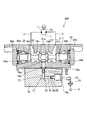
- FIG. 3 is a partial cross-sectional view of the fluid pressure drive device according to the first embodiment of the present invention.
- FIG. 3 is a sectional view taken along the line AA of FIG. 2.
- It is a fluid pressure circuit diagram of a comparative example.
- It is a fluid pressure circuit diagram of a fluid pressure drive concerning a 2nd embodiment of the present invention.
- It is a partial cross section figure of the fluid pressure drive concerning a 3rd embodiment of the present invention.
- FIG. 7 is a sectional view taken along the line BB of FIG. 6.
- It is a partial cross section figure of the fluid pressure drive concerning a 4th embodiment of the present invention, and is a figure corresponding to Drawing 3.
- the fluid pressure drive device 100 is a device for driving a hydraulic motor 1 (fluid pressure motor) whose output shaft 1a is connected to a driven object (not shown) such as a working machine.
- hydraulic oil is used as the working fluid.
- other working fluid such as working water may be used instead of the working oil.
- a fluid pressure drive device 100 includes a hydraulic motor 1 driven by hydraulic fluid supplied from a hydraulic pump 4 (fluid pressure pump), and a first hydraulic fluid passageway as a pair of main passages connected to the hydraulic motor 1.
- a main passage 2 and a second main passage 3 are provided.
- the hydraulic motor 1 is driven by hydraulic oil supplied from the hydraulic pump 4 through one of the first and second main passages 2 and 3.
- the hydraulic pump 4 is driven by a drive source such as an engine or an electric motor.
- the hydraulic pump 4 is a variable displacement pump whose discharge direction and discharge flow rate are adjusted by controlling the swash plate angle by a regulator.
- the hydraulic oil discharged from the hydraulic pump 4 is supplied to the hydraulic motor 1 through one of the first and second main passages 2 and 3, and the hydraulic oil discharged from the hydraulic motor 1 is fed to the first and second main passages 2 and 3.
- the hydraulic circuit of the fluid pressure drive device 100 is configured as a closed circuit.
- the hydraulic oil discharged from the hydraulic pump 4 is supplied to the hydraulic motor 1 through the first main passage 2, the first main passage 2 has a high pressure and the second main passage 3 has a low pressure.
- the second main passage 3 has a high pressure and the first main passage 2 has a low pressure.
- the fluid pressure drive device 100 supplies the flushing circuit 10 for discharging the hydraulic oil from one of the first and second main passages 2 and 3 to the tank 5 and the supply of the hydraulic oil to the first and second main passages 2 and 3. And a charging circuit 20 for performing.
- the flushing circuit 10 discharges the hydraulic oil in the circuit at a constant flow rate, and the charge circuit 20 replenishes the circuit with the hydraulic oil discharged by the flushing circuit 10.
- the hydraulic oil discharged to the tank 5 through the flushing circuit 10 is cooled by the cooler 13, and the charge circuit 20 replenishes the cooled hydraulic oil in the circuit.
- the temperature of the hydraulic oil in the circuit tends to rise.
- the temperature rise of the hydraulic oil in the circuit is suppressed.
- the flushing circuit 10 is provided between the first main passage 2 and the second main passage 3 and is switched by the pressure difference between the main passages 2 and 3 to select a low-pressure side main passage, and a low pressure selection valve 11. It has a flushing passage 12 for guiding the working oil passing through the selection valve 11 to the tank 5, and a cooler 13 provided in the flushing passage 12 for cooling the working oil passing therethrough.
- the low-pressure selection valve 11 includes a first inlet port 14a that communicates with the first main passage 2 through a branch passage 16a, a second inlet port 14b that communicates with the second main passage 3 through a branch passage 16b, and a flushing passage 12 It has three ports, that is, an outlet port 15 communicating with.
- the pilot passage 17a is connected to the branch passage 16a, and the pilot passage 17b is connected to the branch passage 16b. Orifices 18a and 18b are provided in the pilot passages 17a and 17b, respectively. Hydraulic oil from the first and second main passages 2 and 3 acts on both ends of the spool 61 (see FIGS. 2 and 3) of the low pressure selection valve 11 through the pilot passages 17a and 17b, respectively. Therefore, the spool 61 moves due to the pressure difference between the first main passage 2 and the second main passage 3, and the position of the low pressure selection valve 11 is switched.
- the spool 61 is It moves to the right in the figure against the biasing force of the spring 64b.
- the low pressure selection valve 11 is set to the position A (left side in the drawing), the second inlet port 14b and the outlet port 15 are communicated with each other, and the hydraulic oil in the second main passage 3 on the low pressure side is guided to the flushing passage 12. ..
- the spool 61 has the spring 64a. It moves to the left side in the figure against the urging force, the low pressure selection valve 11 is set to the position B (right side in the figure), the first inlet port 14a and the outlet port 15 communicate with each other, and the low pressure side first main passage The second hydraulic oil is guided to the flushing passage 12.
- the low pressure selection valve 11 When the pressure difference between the first main passage 2 and the second main passage 3 is less than the predetermined value, the low pressure selection valve 11 is set to the position C (center in the figure) by the urging force of the springs 64a and 64b. The communication between the first inlet port 14a, the second inlet port 14b and the outlet port 15 is blocked.
- the low-pressure selection valve 11 has three positions and switches depending on the pressure difference between the first main passage 2 and the second main passage 3.
- the charge circuit 20 has a charge pump 21 that sucks and discharges the hydraulic oil in the tank 5, and a charge passage 22 that guides the hydraulic oil discharged from the charge pump 21 to the first and second main passages 2 and 3.
- the charge pump 21 is a fixed displacement hydraulic pump that rotates coaxially with the hydraulic pump 4.
- the charge passage 22 is divided into a first charge passage 22a and a second charge passage 22b on the way, and is connected to the first and second main passages 2 and 3, respectively.
- the first charge passage 22a is provided with a check valve 23 that allows only the flow of hydraulic oil from the charge pump 21 to the first main passage 2
- the second charge passage 22b is provided with a check valve 23 from the charge pump 21 to the second main passage.
- a check valve 24 is provided which allows only the flow of hydraulic oil to the passage 3.
- the hydraulic fluid discharged from the charge pump 21 is replenished to the low-pressure side main passage of the first and second main passages 2 and 3 through the charge passage 22.
- a relief passage 25 is connected upstream of the check valves 23 and 24 in the charge passage 22, and a relief valve 26 is provided in the relief passage 25.
- the excess hydraulic oil discharged from the charge pump 21 to the charge passage 22 is discharged to the tank 5.
- the pressure in the first and second main passages 2 and 3 is maintained at the valve opening pressure of the relief valve 26 or higher.
- the fluid pressure drive device 100 includes a pair of relief valves 6 and 7 provided in opposite directions between the first main passage 2 and the second main passage 3.
- the relief valves 6 and 7 When the relief valves 6 and 7 perform a relief operation, the relief valves 6 and 7 allow the working oil to escape from the high pressure side main passage of the first and second main passages 2 and 3 to the low pressure side main passage through the charge passage 22.
- the relief valve 40 is provided in the flushing passage 12.
- the relief valve 40 is replaced to adjust the flushing flow rate. Since the relief valve 40 has a large number of parts, it takes time to adjust the flushing flow rate. Further, since the relief valve 40 has complicated parts processing, the cost increases. Further, since the relief valve 40 is opened when the pressure in the flushing passage 12 reaches a predetermined opening pressure set in advance, the main valve on the low pressure side of the first and second main passages 2 and 3 is opened. The valve may not be opened depending on the pressure in the passage, and the flushing flow rate may not be stable.
- the flushing flow rate becomes unstable and the cooling capacity of the flushing circuit 10 is increased. Becomes unstable. Further, when the hydraulic oil passes through the relief valve 40, a negative pressure is generated on the downstream side of the relief valve 40, so that the flushing flow rate pulsates and vibrations occur in the pipe forming a part of the flushing passage 12. May occur.
- the flushing passage 12 is provided with an orifice 50 for imparting resistance to the working oil flowing through the flushing passage 12 to adjust the flushing flow rate. It has a (first orifice) and a bent portion 51 formed on the downstream side of the orifice 50.
- the orifice 50 is replaceably provided in the flushing passage 12.
- the flushing flow rate is adjusted simply by replacing the orifice 50.
- the flushing flow rate is adjusted by simply replacing the orifice 50 with an inner diameter corresponding to the required flushing flow rate.
- the orifice 50 since the orifice 50 has a small number of parts and is easy to process, the flushing flow rate can be easily adjusted at low cost. Further, since the flow rate of the orifice 50 is determined by the inlet pressure, a constant flushing flow rate can be secured according to the pressure of the low-pressure main passage of the first and second main passages 2, 3. Therefore, the cooling capacity of the flushing circuit 10 can be stabilized.
- the pressure loss at the bent portion 51 suppresses the pressure drop between the orifice 50 and the bent portion 51, and the negative pressure on the downstream side of the orifice 50 is suppressed. Occurrence can be reduced. Therefore, the pulsation of the flushing flow rate flowing through the flushing passage 12 can be suppressed, so that the vibration of the pipe 75 (see FIG. 3) forming a part of the flushing passage 12 can be prevented.
- FIGS. 2 is a partial cross-sectional view of the fluid pressure drive device 100
- FIG. 3 is a cross-sectional view taken along the line AA of FIG.
- the hydraulic motor 1 and the low pressure selection valve 11 are housed in a case 30.
- the case 30 has a main body 31 and a cover 32 that seals the opening of the main body 31.
- the output shaft 1a, the cylinder block 35, the piston 36, the shoe 37, the swash plate 38, the brake mechanism 39, and the like that configure the hydraulic motor 1 are housed in the internal space of the main body 31.
- the cover portion 32 accommodates the low pressure selection valve 11.
- the low pressure selection valve 11 will be described below.
- the cover portion 32 is formed with a housing hole 33 into which the spool 61 is slidably inserted, and a first flushing hole 12a and a second flushing hole 12b that form a part of the flushing passage 12.
- a first inlet port 14a that communicates with the first main passage 2, a second inlet port 14b that communicates with the second main passage 3, and an outlet port 15 that communicates with the first flushing hole 12a. And are formed.
- the connection and disconnection of the first inlet port 14a, the second inlet port 14b, and the outlet port 15 are switched by the first land portion 61a formed in the central portion of the spool 61.
- the openings at both ends of the accommodation hole 33 are sealed with plugs 62a and 62b, respectively.
- the plug 62a and the second land portion 61b formed on one end side of the spool 61 partition the pilot chamber 63a, and the plug 62b and the third land portion 61c formed on the other end side of the spool 61 form the pilot chamber 63b. Partitioned.
- the hydraulic oil in the first main passage 2 is always guided to the pilot chamber 63a through the pilot passage 17a (see FIG. 1), and the hydraulic oil in the second main passage 3 is always guided to the pilot chamber 63b through the pilot passage 17b. ..
- the pilot chambers 63a and 63b accommodate springs 64a and 64b that bias the spool 61 in a direction in which the volumes of the pilot chambers 63a and 63b increase.
- the spool 61 When the first main passage 2 has a high pressure, the second main passage 3 has a low pressure, and the pressure difference between the first main passage 2 and the second main passage 3 is not less than a predetermined value, the spool 61 is provided with a spring 64b.
- the pilot chamber 63b is moved in the direction of contraction (right side in FIG. 3) against the power.
- the second inlet port 14b communicates with the outlet port 15, and the hydraulic oil in the second main passage 3 on the low pressure side is guided to the flushing passage 12.
- the spool 61 causes the spring 64a.
- the pilot chamber 63a is moved in the direction of contraction (left side in FIG. 3) against the urging force of.
- the first inlet port 14a and the outlet port 15 communicate with each other, and the hydraulic oil in the first main passage 2 on the low pressure side is guided to the flushing passage 12.
- the first flushing hole 12a has an opening 81 on the outer surface of the cover 32 and is linearly formed.
- the opening 81 of the first flushing hole 12a is closed by a plug 85 attached to the cover 32.
- the second flushing hole 12b has an opening 82 on the outer surface of the cover 32 and is formed in a straight line.
- a pipe 75 communicating with the tank 5 is connected to the opening 82.
- the first flushing hole 12a, the second flushing hole 12b, and the pipe 75 form the flushing passage 12.
- the first flushing hole 12a and the second flushing hole 12b communicate with each other at right angles.
- the communicating portion between the first flushing hole 12a and the second flushing hole 12b becomes the bent portion 51.
- the intersection angle of the first flushing hole 12a and the second flushing hole 12b, that is, the bending angle of the bending portion 51 is not limited to 90 degrees, and may be less than 90 degrees or may be greater than 90 degrees.
- An orifice 50 is provided in the first flushing hole 12a. Specifically, the orifice 50 is formed in the orifice plug 52 which is screwed and fixed to the inner circumference of the first flushing hole 12a.
- bent portion 51 is formed on the downstream side of the orifice 50, generation of negative pressure between the orifice 50 and the bent portion 51 in the first flushing hole 12a is reduced. Therefore, the pulsation of the flushing flow rate flowing downstream of the orifice 50 in the flushing passage 12 is suppressed, and the vibration of the pipe 75 can be prevented.
- the plug 85 is removed from the cover 32, the orifice plug 52 is removed from the first flushing hole 12a through the opening 81, and the orifice plug 52 having the orifices 50 with different inner diameters is removed through the opening 81. This is done by mounting the flashing hole 12a in one.
- the flushing flow rate can be adjusted by replacing the orifice 50 incorporated in the cover portion 32. Therefore, the flushing flow rate can be easily adjusted.
- the orifice 50 may be directly formed in the case 30, that is, the orifice 50 may be provided in the case 30 in an unreplaceable manner.
- the cooling capacity of the flushing circuit 10 is adjusted by the orifice 50. Further, since the bent portion 51 is formed on the downstream side of the orifice 50, generation of negative pressure on the downstream side of the orifice 50 is reduced. Therefore, the cooling capacity of the flushing circuit 10 can be easily adjusted and the pulsation of the flushing flow rate can be suppressed.
- FIG. 5 is a fluid pressure circuit diagram of the fluid pressure drive device 200.
- differences from the fluid pressure drive device 100 according to the first embodiment will be described, and configurations similar to the fluid pressure drive device 100 will be denoted by the same reference numerals in the drawings and description thereof will be omitted.
- the fluid pressure drive device 200 differs from the fluid pressure drive device 100 according to the first embodiment in that a chamber 54 is provided in the flushing passage 12 downstream of the orifice 50.
- the chamber 54 is a space having a constant volume, and the flushing oil that has passed through the orifice 50 flows in.
- the chamber 54 having a constant volume on the downstream side of the orifice 50 the flow of the flushing oil passing through the orifice 50 is rectified. This can reduce the generation of negative pressure on the downstream side of the orifice 50. Therefore, the pulsation of the flushing flow rate flowing downstream of the orifice 50 in the flushing passage 12 is suppressed, and the vibration of the pipe 75 can be prevented.
- FIGS. 6 and 7 are partial cross-sectional views of the fluid pressure drive device 300
- FIG. 7 is a cross-sectional view taken along the line BB of FIG.
- differences from the fluid pressure drive device 100 according to the first embodiment will be described, and configurations similar to the fluid pressure drive device 100 will be denoted by the same reference numerals in the drawings and description thereof will be omitted.
- the fluid pressure drive device 300 is different from the fluid pressure drive device 100 according to the first embodiment in that the orifice 50 and the bent portion 51 are incorporated in a flow rate adjustment block 70 that is separate from the case 30. This will be described in detail below.
- the flow rate adjusting block 70 is fixed to the side surface 32 a of the cover portion 32 of the case 30 with a plurality of bolts 76. In this way, the flow rate adjusting block 70 is detachably fixed to the case 30.
- the flow rate adjusting block 70 has an opening 72a on a surface 70a that contacts the side surface 32a of the cover 32, and a second flushing hole 72 communicating with the first flushing hole 12a formed on the cover 32, and a surface.
- a third flushing hole 73 having an opening 73a is formed on a surface 70b different from 70a.
- the first flushing hole 12a and the second flushing hole 72 communicate with each other linearly.
- a pipe 75 communicating with the tank 5 is connected to the opening 73 a of the third flushing hole 73.
- the first flushing hole 12a, the second flushing hole 72, the third flushing hole 73, and the pipe 75 constitute the flushing passage 12.
- the second flushing hole 72 and the third flushing hole 73 are formed in a linear shape, and their ends communicate with each other at right angles.
- the communicating portion between the second flushing hole 72 and the third flushing hole 73 becomes the bent portion 51.
- the orifice 50 is provided in the second flushing hole 72. Specifically, the orifice 50 is formed in the orifice plug 52 which is screwed and fixed to the inner circumference of the second flushing hole 72. As described above, the orifice 50 and the bent portion 51 are incorporated in the flow rate adjusting block 70 which is separate from the case 30 in which the hydraulic motor 1 and the low pressure selection valve 11 are housed.
- the flow rate adjusting block 70 When adjusting the flushing flow rate, the flow rate adjusting block 70 is removed from the cover 32, the orifice plug 52 is removed from the second flushing hole 72 through the opening 72a, and the orifice plug 52 having the orifices 50 having different inner diameters is opened. This is performed by mounting the second flushing hole 72 through 72a. In this way, the flushing flow rate can be adjusted by removing the flow rate adjusting block 70 from the cover 32 and replacing the orifice 50 incorporated in the flow rate adjusting block 70. Therefore, the flushing flow rate can be easily adjusted.
- the orifice 50 is incorporated in the flow rate adjusting block 70 which is detachably fixed to the case 30, the orifice 50 is changed from the type in which the flushing flow rate is adjusted by the relief valve 40 as shown in the comparative example shown in FIG. 50 makes it easy to change to a type that adjusts the flushing flow rate. That is, it becomes easy to select the flow rate adjusting block 70 in which the orifice 50 is incorporated and the flow rate adjusting block in which the relief valve 40 is incorporated.
- FIG. 8 is a fluid pressure circuit diagram of the fluid pressure drive device 400
- FIG. 9 is a partial cross-sectional view of the fluid pressure drive device 400.
- differences from the fluid pressure drive devices 100 and 300 according to the first and third embodiments will be described, and the same configurations as the fluid pressure drive devices 100 and 300 are denoted by the same reference numerals in the drawings. The description is omitted.
- the flushing passage 12 is provided on the downstream side of the bent portion 51 in addition to the replaceable first orifice 50 and the bent portion 51 formed on the downstream side of the first orifice 50. It also has a replaceable second orifice 55.
- the second orifice 55 is provided in the third flushing hole 73.
- the second orifice 55 is formed in the orifice plug 56 that is screwed and fixed to the inner circumference of the third flushing hole 73.
- the orifice plug 56 is attached to and detached from the third flushing hole 73 through the opening 73a.
- the second orifice 55 is provided on the downstream side of the first orifice 50, the pressure drop between the first orifice 50 and the second orifice 55 is suppressed by the pressure loss at the second orifice 55.
- the second orifice 55 also has a function of rectifying the flow of the flushing oil that has passed through the first orifice 50, similarly to the chamber 54 of the fluid pressure drive device 200 according to the second embodiment. Accordingly, it is possible to more effectively reduce the generation of negative pressure on the downstream side of the first orifice 50. Therefore, the pulsation of the flushing flow rate flowing downstream of the orifice 50 in the flushing passage 12 is suppressed, and the vibration of the pipe 75 can be prevented.
- the opening area of the first orifice 50 is preferably smaller than the opening area of the second orifice 55. This is because the first orifice 50 has a function of adjusting the flushing flow rate, while the second orifice 55 has a function of rectifying the flow of flushing oil, so that the opening area of the second orifice 55 does not need to be small. This is because. Therefore, when adjusting the flushing flow rate, the first orifice 50 is mainly replaced.
- both the second orifice 55 and the chamber 54 described in the second embodiment may be provided in the flushing passage 12.
- the second orifice 55 is preferably provided on the downstream side of the chamber 54.
- the fluid pressure drive devices 100, 200, 300, 400 are connected to a hydraulic motor (fluid pressure motor) 1 driven by a working fluid supplied from a hydraulic pump (fluid pressure pump) 4, and connected to the hydraulic motor 1.
- the flushing circuit 10 is provided between the pair of main passages 2 and 3 and is switched by a pressure difference between the pair of main passages 2 and 3 to select a low pressure side main passage, and a low pressure selection valve 11.
- a flushing passage 12 for guiding the hydraulic oil passing through the valve 11 to the tank 5, and the flushing passage 12 has a first orifice 50 and a bent portion 51 formed on the downstream side of the first orifice 50. ..
- the cooling capacity of the flushing circuit 10 is adjusted by the first orifice 50. Further, since the bent portion 51 is formed on the downstream side of the first orifice 50, generation of negative pressure on the downstream side of the first orifice 50 is reduced. Therefore, the cooling capacity of the flushing circuit 10 can be easily adjusted and the pulsation of the flushing flow rate can be suppressed.
- a chamber 54 is provided in the flushing passage 12 downstream of the first orifice 50.
- the flushing passage 12 further has a second orifice 55 provided on the downstream side of the bent portion 51.
- the second orifice 55 is provided on the downstream side of the first orifice 50, it is possible to more effectively reduce the generation of negative pressure on the downstream side of the first orifice 50, and to reduce the pulsation of the flushing flow rate. Occurrence can be suppressed.
- the opening area of the first orifice 50 is smaller than the opening area of the second orifice 55.
- the first orifice 50 has a function of adjusting the flushing flow rate, while the second orifice 55 has a function of rectifying the flow of flushing fluid.
- the fluid pressure drive devices 100, 200, 300 are a case 30 that houses the hydraulic motor 1 and the low pressure selection valve 11, and a flow rate that is detachably fixed to the case 30 and that includes the first orifice 50 and the bent portion 51.
- the adjustment block 70 is further provided.
- the type in which the flushing flow rate is adjusted by the relief valve 40 changes the flushing flow rate by the first orifice 50. It is easy to change to the type to be adjusted.
- the mode in which the hydraulic oil of the flushing circuit 10 is discharged to the tank 5 has been described.
- the hydraulic oil of the flushing circuit 10 may be introduced into the case 30 of the hydraulic motor 1 and then discharged to the tank 5. That is, the hydraulic oil of the flushing circuit 10 may be discharged to the tank 5 via the case 30 of the hydraulic motor 1.
Landscapes
- Engineering & Computer Science (AREA)
- General Engineering & Computer Science (AREA)
- Mechanical Engineering (AREA)
- Physics & Mathematics (AREA)
- Fluid Mechanics (AREA)
- Chemical & Material Sciences (AREA)
- Analytical Chemistry (AREA)
- Fluid-Pressure Circuits (AREA)
Abstract
流体圧駆動装置(100)は、一対のメイン通路(2,3)の一方からタンク(5)へ作動流体を排出するフラッシング回路(10)を備え、フラッシング回路(10)は、一対のメイン通路(2,3)間に設けられて一対のメイン通路(2,3)間の圧力差によって切り換わり、低圧側のメイン通路を選択する低圧選択弁(11)と、低圧選択弁(11)を通過する作動流体をタンク(5)へ導くフラッシング通路(12)と、を有し、フラッシング通路(12)は、第1オリフィス(50)と、第1オリフィス(50)の下流側に形成された屈曲部(51)と、を有する。
Description
本発明は、流体圧駆動装置に関するものである。
油圧モータを駆動する油圧駆動装置において、作動油の温度上昇を抑制するためのフラッシング回路を備えるものがある(JP2002-227998A参照)。
JP2002-227998Aには、一対の主管路にフラッシングラインを介して接続されたフラッシング弁と、一次側がフラッシング弁の排出側に接続されたリリーフ弁と、を備えるフラッシング回路が開示されている。
JP2002-227998Aに記載のフラッシング回路では、低圧側の主管路からリリーフ弁を通じて作動油が排出されるため、フラッシング回路の冷却能力を調整する際には、リリーフ弁の設定を調整する必要がある。リリーフ弁は部品点数が多いため、フラッシング回路の冷却能力の調整には多大な労力を要する。また、作動油がリリーフ弁を通過する際に、リリーフ弁の下流側で負圧が発生することに起因して、フラッシング流量が脈動し配管に振動が発生することがある。
本発明は、フラッシング回路の冷却能力の調整を容易に行うことができ、かつフラッシング流量の脈動の発生を抑制することができる流体圧駆動装置を提供することを目的とする。
本発明のある態様によれば、流体圧ポンプから供給される作動流体によって駆動する流体圧モータと、前記流体圧モータに接続され、前記流体圧ポンプから供給される作動流体がいずれか一方に導かれる一対のメイン通路と、前記一対のメイン通路の一方からタンクへ作動流体を排出するフラッシング回路と、を備え、前記フラッシング回路は、前記一対のメイン通路間に設けられて当該一対のメイン通路間の圧力差によって切り換わり、低圧側のメイン通路を選択する低圧選択弁と、前記低圧選択弁を通過する作動流体を前記タンクへ導くフラッシング通路と、を有し、前記フラッシング通路は、第1オリフィスと、前記第1オリフィスの下流側に形成された屈曲部と、を有する。
以下、図面を参照して、本発明の実施形態について説明する。
<第1実施形態>
図1~3を参照して、本発明の第1実施形態に係る流体圧駆動装置100について説明する。
図1~3を参照して、本発明の第1実施形態に係る流体圧駆動装置100について説明する。
流体圧駆動装置100は、出力軸1aが作業機等の被駆動対象(図示せず)に連結された油圧モータ1(流体圧モータ)を駆動するための装置である。流体圧駆動装置100では、作動流体として作動油が用いられる。なお、作動油に代わり、作動水等の他の作動流体を用いてもよい。
図1に示すように、流体圧駆動装置100は、油圧ポンプ4(流体圧ポンプ)から供給される作動油によって駆動する油圧モータ1と、油圧モータ1に接続された一対のメイン通路としての第1メイン通路2及び第2メイン通路3と、を備える。油圧モータ1は、第1及び第2メイン通路2,3の一方を通じて油圧ポンプ4から供給される作動油によって駆動する。
油圧ポンプ4は、エンジンや電動モータ等の駆動源により駆動される。油圧ポンプ4は、レギュレータにより斜板角度が制御されることによって吐出方向と吐出流量が調整される可変容量型ポンプである。油圧ポンプ4から吐出される作動油が第1及び第2メイン通路2,3の一方を通じて油圧モータ1へ供給され、油圧モータ1から排出される作動油が第1及び第2メイン通路2,3の他方を通じて油圧ポンプ4の吸込側へと戻る。このように、流体圧駆動装置100の油圧回路は、閉回路にて構成される。油圧ポンプ4から吐出される作動油が第1メイン通路2を通じて油圧モータ1へ供給される場合には、第1メイン通路2が高圧、第2メイン通路3が低圧となる。一方、油圧ポンプ4から吐出される作動油が第2メイン通路3を通じて油圧モータ1へ供給される場合には、第2メイン通路3が高圧、第1メイン通路2が低圧となる。
流体圧駆動装置100は、第1及び第2メイン通路2,3の一方からタンク5へ作動油を排出するフラッシング回路10と、第1及び第2メイン通路2,3への作動油の補給を行うチャージ回路20と、をさらに備える。
フラッシング回路10は回路内の作動油を一定流量排出し、チャージ回路20はフラッシング回路10によって排出された分の作動油を回路内に補給する。フラッシング回路10を通じてタンク5へ排出される作動油はクーラ13によって冷却され、チャージ回路20はその冷却された作動油を回路内に補給する。閉回路では、回路内を循環する作動油の量が少ないため、回路内の作動油の温度が上昇し易い傾向にある。しかし、フラッシング回路10及びチャージ回路20の作用により、回路内の作動油の温度上昇が抑制される。
フラッシング回路10は、第1メイン通路2と第2メイン通路3の間に設けられて両メイン通路2,3の圧力差によって切り換わり、低圧側のメイン通路を選択する低圧選択弁11と、低圧選択弁11を通過する作動油をタンク5へ導くフラッシング通路12と、フラッシング通路12に設けられ、通過する作動油を冷却するクーラ13と、を有する。
低圧選択弁11は、分岐通路16aを介して第1メイン通路2と連通する第1入口ポート14a、分岐通路16bを介して第2メイン通路3と連通する第2入口ポート14b、及びフラッシング通路12に連通する出口ポート15の3ポートを有する。
分岐通路16aにはパイロット通路17aが接続され、分岐通路16bにはパイロット通路17bが接続される。パイロット通路17a,17bには、それぞれオリフィス18a、18bが設けられる。低圧選択弁11のスプール61(図2及び3参照)の両端には、それぞれパイロット通路17a、17bを通じて第1及び第2メイン通路2,3からの作動油が作用する。したがって、第1メイン通路2と第2メイン通路3の圧力差によってスプール61が移動し、低圧選択弁11のポジションが切り換わる。
具体的には、第1メイン通路2が高圧、第2メイン通路3が低圧で、かつ第1メイン通路2と第2メイン通路3との圧力差が所定値以上の場合には、スプール61はスプリング64bの付勢力に抗して図中右側へ移動する。これにより、低圧選択弁11はポジションA(図中左側)に設定され、第2入口ポート14bと出口ポート15が連通し、低圧側の第2メイン通路3の作動油がフラッシング通路12に導かれる。
一方、第1メイン通路2が低圧、第2メイン通路3が高圧で、かつ第1メイン通路2と第2メイン通路3との圧力差が所定値以上の場合には、スプール61はスプリング64aの付勢力に抗して図中左側へ移動し、低圧選択弁11はポジションB(図中右側)に設定され、第1入口ポート14aと出口ポート15とが連通し、低圧側の第1メイン通路2の作動油がフラッシング通路12に導かれる。
また、第1メイン通路2と第2メイン通路3との圧力差が所定値未満の場合には、スプリング64a及び64bの付勢力によって低圧選択弁11はポジションC(図中中央)に設定され、第1入口ポート14a、第2入口ポート14bと出口ポート15との連通が遮断される。
このように、低圧選択弁11は3ポジションを有し、第1メイン通路2と第2メイン通路3との圧力差によって切り換わる。
チャージ回路20は、タンク5の作動油を吸い込んで吐出するチャージポンプ21と、チャージポンプ21から吐出された作動油を第1及び第2メイン通路2,3に導くチャージ通路22と、を有する。チャージポンプ21は、油圧ポンプ4と同軸回転する固定容量型油圧ポンプである。
チャージ通路22は、途中で第1チャージ通路22aと第2チャージ通路22bに分かれ、それぞれ第1及び第2メイン通路2,3に接続される。第1チャージ通路22aには、チャージポンプ21から第1メイン通路2への作動油の流れのみを許容する逆止弁23が設けられ、第2チャージ通路22bには、チャージポンプ21から第2メイン通路3への作動油の流れのみを許容する逆止弁24が設けられる。チャージポンプ21から吐出された作動油は、チャージ通路22を通じて第1及び第2メイン通路2,3のうち低圧側のメイン通路へ補給される。
チャージ通路22における逆止弁23,24の上流側にはリリーフ通路25が接続され、リリーフ通路25にはリリーフ弁26が設けられる。このように、チャージポンプ21からチャージ通路22に吐出される余剰の作動油はタンク5へと排出される。これにより、チャージポンプ21の駆動時には、第1及び第2メイン通路2,3の圧力は、リリーフ弁26の開弁圧以上に保たれることになる。
流体圧駆動装置100は、第1メイン通路2と第2メイン通路3の間に、互いに逆向きに設けられた一対のリリーフ弁6,7を備える。リリーフ弁6,7は、リリーフ動作した際には、第1及び第2メイン通路2,3のうち高圧側のメイン通路から低圧側のメイン通路へチャージ通路22を通じて作動油を逃がす。
ここで、図4を参照して比較例について説明する。比較例では、フラッシング通路12にリリーフ弁40が設けられる。フラッシング回路10による冷却能力を調整する際には、リリーフ弁40を交換することによってフラッシング流量が調整される。リリーフ弁40は部品点数が多いため、フラッシング流量の調整には時間がかかる。また、リリーフ弁40は部品加工が複雑であるため、コストが嵩む。また、リリーフ弁40は、フラッシング通路12の圧力が予め設定された所定の開弁圧力に達した場合に開弁するものであるため、第1及び第2メイン通路2,3の低圧側のメイン通路の圧力によっては開弁しないこともあり、フラッシング流量が安定しないという問題もある。特に、第1及び第2メイン通路2,3の低圧側のメイン通路の作動油を抜き出して他の油圧機器の駆動に利用する場合には、フラッシング流量が不安定となり、フラッシング回路10による冷却能力も不安定となる。さらに、作動油がリリーフ弁40を通過する際に、リリーフ弁40の下流側で負圧が発生することに起因して、フラッシング流量が脈動しフラッシング通路12の一部を構成する配管に振動が発生することがある。
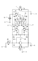
比較例における上記問題点の対応策として、本実施形態では、図1に示すように、フラッシング通路12は、フラッシング通路12を流れる作動油に抵抗を付与してフラッシング流量を調整するためのオリフィス50(第1オリフィス)と、オリフィス50の下流側に形成された屈曲部51と、を有する。
オリフィス50は、フラッシング通路12に交換可能に設けられる。フラッシング回路10による作動油の冷却能力を調整する際には、オリフィス50を交換するだけでフラッシング流量が調整される。具体的には、必要なフラッシング流量に対応する内径を有するオリフィス50に交換するだけで、フラッシング流量が調整される。このように、オリフィス50は部品点数が少なくかつ加工も容易であるため、容易に低コストでフラッシング流量を調整することができる。また、オリフィス50は、入口圧力によって流量が決まるため、第1及び第2メイン通路2,3の低圧側のメイン通路の圧力に応じて、一定のフラッシング流量を確保することができる。よって、フラッシング回路10による冷却能力を安定させることができる。さらに、オリフィス50の下流側には屈曲部51があるため、屈曲部51での圧力損失によって、オリフィス50と屈曲部51の間の圧力低下が抑制され、オリフィス50の下流側での負圧の発生を軽減することができる。よって、フラッシング通路12を流れるフラッシング流量の脈動の発生を抑制することができるため、フラッシング通路12の一部を構成する配管75(図3参照)の振動の発生を防止することができる。
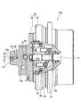
次に、図2及び3を参照して、流体圧駆動装置100の構造について説明する。図2は流体圧駆動装置100の一部断面図であり、図3は図2のA-A線に沿う断面図である。
油圧モータ1及び低圧選択弁11は、ケース30に収容される。ケース30は、本体部31と、本体部31の開口部を封止するカバー部32と、を有する。本体部31の内部空間には、油圧モータ1を構成する出力軸1a、シリンダブロック35、ピストン36、シュー37、斜板38、及びブレーキ機構39等が収容される。カバー部32には、低圧選択弁11が収容される。
以下では、低圧選択弁11について説明する。
カバー部32には、スプール61が摺動自在に挿入された収容孔33と、フラッシング通路12の一部を構成する第1フラッシング穴12a及び第2フラッシング穴12bと、が形成される。
収容孔33の内周には、第1メイン通路2と連通する第1入口ポート14aと、第2メイン通路3と連通する第2入口ポート14bと、第1フラッシング穴12aに連通する出口ポート15と、が形成される。第1入口ポート14a、第2入口ポート14bと出口ポート15との連通と遮断は、スプール61の中央部に形成された第1ランド部61aによって切り換えられる。
収容孔33の両端の開口部は、それぞれプラグ62a,62bにて封止される。プラグ62aとスプール61の一端側に形成された第2ランド部61bとによってパイロット室63aが区画され、プラグ62bとスプール61の他端側に形成された第3ランド部61cとによってパイロット室63bが区画される。
パイロット室63aには、パイロット通路17a(図1参照)を通じて第1メイン通路2の作動油が常時導かれ、パイロット室63bには、パイロット通路17bを通じて第2メイン通路3の作動油が常時導かれる。パイロット室63a,63b内には、それぞれスプール61をパイロット室63a,63bの容積が拡大する方向に付勢するスプリング64a、64bが収容される。
第1メイン通路2が高圧、第2メイン通路3が低圧で、かつ第1メイン通路2と第2メイン通路3との圧力差が所定値以上の場合には、スプール61は、スプリング64bの付勢力に抗してパイロット室63bを縮小する方向(図3中右側)へ移動する。これにより、第2入口ポート14bと出口ポート15が連通し、低圧側である第2メイン通路3の作動油がフラッシング通路12に導かれる。
一方、第1メイン通路2が低圧、第2メイン通路3が高圧で、かつ第1メイン通路2と第2メイン通路3との圧力差が所定値以上の場合には、スプール61は、スプリング64aの付勢力に抗してパイロット室63aを縮小する方向(図3中左側)へ移動する。これにより、第1入口ポート14aと出口ポート15が連通し、低圧側である第1メイン通路2の作動油がフラッシング通路12に導かれる。
第1フラッシング穴12aは、カバー部32の外面に開口部81を有し、直線状に形成される。第1フラッシング穴12aの開口部81は、カバー部32に取り付けられるプラグ85によって閉塞される。第2フラッシング穴12bは、カバー部32の外面に開口部82を有し、直線状に形成される。開口部82には、タンク5に連通する配管75が接続される。第1フラッシング穴12a、第2フラッシング穴12b、及び配管75によって、フラッシング通路12が構成される。
第1フラッシング穴12aと第2フラッシング穴12bは、互いに直交して連通する。第1フラッシング穴12aと第2フラッシング穴12bの連通部が、屈曲部51となる。第1フラッシング穴12aと第2フラッシング穴12bの交差角度、つまり屈曲部51の屈曲角度は90度に限られず、90度未満であってもよいし、90度よりも大きくてもよい。
第1フラッシング穴12aには、オリフィス50が設けられる。具体的には、オリフィス50は、第1フラッシング穴12aの内周に螺合して固定されるオリフィスプラグ52に形成される。
オリフィス50の下流側には屈曲部51が形成されるため、第1フラッシング穴12aにおけるオリフィス50と屈曲部51の間での負圧の発生が軽減される。よって、フラッシング通路12におけるオリフィス50の下流を流れるフラッシング流量の脈動の発生が抑制され、配管75の振動の発生を防止することができる。
フラッシング流量を調整する際には、カバー部32からプラグ85を取り外し、開口部81を通じて第1フラッシング穴12aからオリフィスプラグ52を取り外し、内径の異なるオリフィス50を有するオリフィスプラグ52を開口部81を通じて第1フラッシング穴12aに装着することによって行う。このように、フラッシング流量の調整は、カバー部32に組み込まれたオリフィス50を交換することによって行うことができる。したがって、容易にフラッシング流量を調整することができる。
なお、本実施形態では、オリフィス50が交換可能にケース30に設けられる形態について説明した。これに代えて、オリフィス50をケース30に直接形成するようにしてもよい、つまり、オリフィス50は、交換不能にケース30に設けられる構成であってもよい。
以上の第1実施形態によれば、以下に示す効果を奏する。
フラッシング回路10の冷却能力はオリフィス50によって調整される。また、オリフィス50の下流側には屈曲部51が形成されるため、オリフィス50の下流側での負圧の発生が軽減される。よって、フラッシング回路10の冷却能力の調整を容易に行うことができ、かつフラッシング流量の脈動の発生を抑制することができる。
<第2実施形態>
次に、図5を参照して、本発明の第2実施形態に係る200について説明する。図5は流体圧駆動装置200の流体圧回路図である。以下では、上記第1実施形態に係る流体圧駆動装置100と異なる点について説明し、流体圧駆動装置100と同様の構成には、図面中に同一の符号を付して説明を省略する。
次に、図5を参照して、本発明の第2実施形態に係る200について説明する。図5は流体圧駆動装置200の流体圧回路図である。以下では、上記第1実施形態に係る流体圧駆動装置100と異なる点について説明し、流体圧駆動装置100と同様の構成には、図面中に同一の符号を付して説明を省略する。
流体圧駆動装置200は、フラッシング通路12におけるオリフィス50の下流側にチャンバ54が設けられる点で、上記第1実施形態に係る流体圧駆動装置100と異なる。
チャンバ54は、一定の容積を有する空間であって、オリフィス50を通過したフラッシング油が流入する。オリフィス50の下流側に一定の容積を有するチャンバ54が設けられることによって、オリフィス50を通過したフラッシング油の流れが整流される。これにより、オリフィス50の下流側での負圧の発生を軽減することができる。よって、フラッシング通路12におけるオリフィス50の下流を流れるフラッシング流量の脈動の発生が抑制され、配管75の振動の発生を防止することができる。
<第3実施形態>
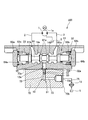
次に、図6及び7を参照して、本発明の第3実施形態に係る300について説明する。図6は流体圧駆動装置300の一部断面図であり、図7は図6のB-B線に沿う断面図である。以下では、上記第1実施形態に係る流体圧駆動装置100と異なる点について説明し、流体圧駆動装置100と同様の構成には、図面中に同一の符号を付して説明を省略する。
次に、図6及び7を参照して、本発明の第3実施形態に係る300について説明する。図6は流体圧駆動装置300の一部断面図であり、図7は図6のB-B線に沿う断面図である。以下では、上記第1実施形態に係る流体圧駆動装置100と異なる点について説明し、流体圧駆動装置100と同様の構成には、図面中に同一の符号を付して説明を省略する。
流体圧駆動装置300は、オリフィス50と屈曲部51が、ケース30とは別体の流量調整用ブロック70に組み込まれている点で、上記第1実施形態に係る流体圧駆動装置100と異なる。以下に詳しく説明する。
流量調整用ブロック70は、ケース30におけるカバー部32の側面32aに、複数のボルト76によって固定される。このように、流量調整用ブロック70はケース30に対して取り外し可能に固定される。
流量調整用ブロック70には、カバー部32の側面32aに接触する面70aに開口部72aを有し、カバー部32に形成された第1フラッシング穴12aに連通する第2フラッシング穴72と、面70aとは異なる面70bに開口部73aを有する第3フラッシング穴73と、が形成される。第1フラッシング穴12aと第2フラッシング穴72は、直線状に連通する。第3フラッシング穴73の開口部73aには、タンク5に連通する配管75が接続される。第1フラッシング穴12a、第2フラッシング穴72、第3フラッシング穴73、及び配管75によって、フラッシング通路12が構成される。
第2フラッシング穴72と第3フラッシング穴73は、直線状に形成され、それぞれの端部が互いに直交して連通する。第2フラッシング穴72と第3フラッシング穴73の連通部が、屈曲部51となる。
オリフィス50は、第2フラッシング穴72に設けられる。具体的には、オリフィス50は、第2フラッシング穴72の内周に螺合して固定されるオリフィスプラグ52に形成される。このように、オリフィス50と屈曲部51は、油圧モータ1及び低圧選択弁11が収容されたケース30とは別体の流量調整用ブロック70に組み込まれている。
フラッシング流量を調整する際には、カバー部32から流量調整用ブロック70を取り外し、開口部72aを通じて第2フラッシング穴72からオリフィスプラグ52を取り外し、内径の異なるオリフィス50を有するオリフィスプラグ52を開口部72aを通じて第2フラッシング穴72に装着することによって行う。このように、フラッシング流量の調整は、カバー部32から流量調整用ブロック70を取り外し、流量調整用ブロック70に組み込まれたオリフィス50を交換することによって行うことができる。したがって、容易にフラッシング流量を調整することができる。
また、オリフィス50はケース30に取り外し可能に固定された流量調整用ブロック70に組み込まれているため、図4に示す比較例で示したようなリリーフ弁40によってフラッシング流量を調整するタイプから、オリフィス50によってフラッシング流量を調整するタイプへの変更が容易となる。つまり、オリフィス50が組み込まれた流量調整用ブロック70と、リリーフ弁40が組み込まれた流量調整用ブロックとの選択が容易となる。
<第4実施形態>
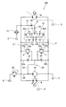
次に、図8及び9を参照して、本発明の第4実施形態に係る400について説明する。図8は流体圧駆動装置400の流体圧回路図であり、図9は流体圧駆動装置400の一部断面図である。以下では、上記第1,3実施形態に係る流体圧駆動装置100,300と異なる点について説明し、流体圧駆動装置100,300と同様の構成には、図面中に同一の符号を付して説明を省略する。
次に、図8及び9を参照して、本発明の第4実施形態に係る400について説明する。図8は流体圧駆動装置400の流体圧回路図であり、図9は流体圧駆動装置400の一部断面図である。以下では、上記第1,3実施形態に係る流体圧駆動装置100,300と異なる点について説明し、流体圧駆動装置100,300と同様の構成には、図面中に同一の符号を付して説明を省略する。
流体圧駆動装置400は、フラッシング通路12は、交換可能に設けられた第1オリフィス50と、第1オリフィス50の下流側に形成された屈曲部51とに加えて、屈曲部51の下流側に交換可能に設けられた第2オリフィス55も有する。
図9に示すように、第2オリフィス55は、第3フラッシング穴73に設けられる。具体的には、第2オリフィス55は、第3フラッシング穴73の内周に螺合して固定されるオリフィスプラグ56に形成される。オリフィスプラグ56は、開口部73aを通じて第3フラッシング穴73に対して着脱される。
第1オリフィス50の下流側に第2オリフィス55が設けられるため、第2オリフィス55での圧力損失によって、第1オリフィス50と第2オリフィス55の間の圧力低下が抑制される。また、第2オリフィス55は、上記第2実施形態に係る流体圧駆動装置200のチャンバ54と同様に、第1オリフィス50を通過したフラッシング油の流れを整流する作用も有する。これにより、第1オリフィス50の下流側での負圧の発生をより効果的に軽減することができる。よって、フラッシング通路12におけるオリフィス50の下流を流れるフラッシング流量の脈動の発生が抑制され、配管75の振動の発生を防止することができる。
第1オリフィス50の開口面積は、第2オリフィス55の開口面積と比較して小さいのが好ましい。これは、第1オリフィス50がフラッシング流量を調整する機能を有するのに対して、第2オリフィス55はフラッシング油の流れを整流する機能を有するため、第2オリフィス55の開口面積は小さい必要がないためである。したがって、フラッシング流量を調整する際には、主に第1オリフィス50を交換することによって行われる。
なお、第2オリフィス55と上記第2実施形態で説明したチャンバ54との双方をフラッシング通路12に設けるようにしてもよい。その場合には、第2オリフィス55はチャンバ54の下流側に設けるのが好ましい。
以下、本発明の実施形態の構成、作用、及び効果をまとめて説明する。
流体圧駆動装置100,200,300,400は、油圧ポンプ(流体圧ポンプ)4から供給される作動流体によって駆動する油圧モータ(流体圧モータ)1と、油圧モータ1に接続され、油圧ポンプ4から供給される作動油(作動流体)がいずれか一方に導かれる一対のメイン通路2,3と、一対のメイン通路2,3の一方からタンク5へ作動油を排出するフラッシング回路10と、を備え、フラッシング回路10は、一対のメイン通路2,3間に設けられて一対のメイン通路2,3間の圧力差によって切り換わり、低圧側のメイン通路を選択する低圧選択弁11と、低圧選択弁11を通過する作動油をタンク5へ導くフラッシング通路12と、を有し、フラッシング通路12は、第1オリフィス50と、第1オリフィス50の下流側に形成された屈曲部51と、を有する。
この構成では、フラッシング回路10の冷却能力は第1オリフィス50によって調整される。また、第1オリフィス50の下流側には屈曲部51が形成されるため、第1オリフィス50の下流側での負圧の発生が軽減される。よって、フラッシング回路10の冷却能力の調整を容易に行うことができ、かつフラッシング流量の脈動の発生を抑制することができる。
また、フラッシング通路12には、第1オリフィス50の下流側にチャンバ54が設けられる。
この構成では、第1オリフィス50を通過したフラッシング油の流れがチャンバ54によって整流されるため、第1オリフィスの下流側での負圧の発生を軽減することができ、フラッシング流量の脈動の発生を抑制することができる。
また、フラッシング通路12は、屈曲部51の下流側に設けられた第2オリフィス55をさらに有する。
この構成では、第1オリフィス50の下流側に第2オリフィス55が設けられるため、第1オリフィス50の下流側での負圧の発生をより効果的に軽減することができ、フラッシング流量の脈動の発生を抑制することができる。
また、第1オリフィス50の開口面積は、第2オリフィス55の開口面積と比較して小さい。
この構成では、第1オリフィス50がフラッシング流量を調整する機能を有するのに対して、第2オリフィス55はフラッシング流体の流れを整流する機能を有する。
また、流体圧駆動装置100,200,300は、油圧モータ1及び低圧選択弁11を収容するケース30と、ケース30に取り外し可能に固定され、第1オリフィス50と屈曲部51が組み込まれた流量調整用ブロック70と、をさらに備える。
この構成では、第1オリフィス50はケース30に取り外し可能に固定された流量調整用ブロック70に組み込まれているため、リリーフ弁40によってフラッシング流量を調整するタイプから、第1オリフィス50によってフラッシング流量を調整するタイプへの変更が容易となる。
以上、本発明の実施形態について説明したが、上記実施形態は本発明の適用例の一部を示したに過ぎず、本発明の技術的範囲を上記実施形態の具体的構成に限定する趣旨ではない。
例えば、上記各実施形態では、フラッシング回路10の作動油がタンク5へ排出される形態について説明した。これに代わり、フラッシング回路10の作動油を油圧モータ1のケース30内に導いた後、タンク5へ排出するようにしてもよい。つまり、フラッシング回路10の作動油を油圧モータ1のケース30を経由してタンク5へ排出するようにしてもよい。
本願は2018年11月26日に日本国特許庁に出願された特願2018-220609に基づく優先権を主張し、この出願の全ての内容は参照により本明細書に組み込まれる。
Claims (5)
- 流体圧駆動装置であって、
流体圧ポンプから供給される作動流体によって駆動する流体圧モータと、
前記流体圧モータに接続され、前記流体圧ポンプから供給される作動流体がいずれか一方に導かれる一対のメイン通路と、
前記一対のメイン通路の一方からタンクへ作動流体を排出するフラッシング回路と、を備え、
前記フラッシング回路は、
前記一対のメイン通路間に設けられて当該一対のメイン通路間の圧力差によって切り換わり、低圧側のメイン通路を選択する低圧選択弁と、
前記低圧選択弁を通過する作動流体を前記タンクへ導くフラッシング通路と、を有し、
前記フラッシング通路は、第1オリフィスと、前記第1オリフィスの下流側に形成された屈曲部と、を有する流体圧駆動装置。 - 請求項1に記載の流体圧駆動装置であって、
前記フラッシング通路には、前記第1オリフィスの下流側にチャンバが設けられる流体圧駆動装置。 - 請求項1に記載の流体圧駆動装置であって、
前記フラッシング通路は、前記屈曲部の下流側に設けられた第2オリフィスをさらに有する流体圧駆動装置。 - 請求項3に記載の流体圧駆動装置であって、
前記第1オリフィスの開口面積は、前記第2オリフィスの開口面積と比較して小さい流体圧駆動装置。 - 請求項1に記載の流体圧駆動装置であって、
前記流体圧モータ及び前記低圧選択弁を収容するケースと、
前記ケースに取り外し可能に固定され、前記第1オリフィスと前記屈曲部が組み込まれた流量調整用ブロックと、をさらに備える流体圧駆動装置。
Priority Applications (4)
| Application Number | Priority Date | Filing Date | Title |
|---|---|---|---|
| US16/760,800 US11181194B2 (en) | 2018-11-26 | 2019-09-12 | Fluid pressure drive device |
| CN201980005597.XA CN111492146A (zh) | 2018-11-26 | 2019-09-12 | 流体压驱动装置 |
| EP19872265.4A EP3686441B1 (en) | 2018-11-26 | 2019-09-12 | Fluid-pressure driving device |
| KR1020207011341A KR102309226B1 (ko) | 2018-11-26 | 2019-09-12 | 유체압 구동 장치 |
Applications Claiming Priority (2)
| Application Number | Priority Date | Filing Date | Title |
|---|---|---|---|
| JP2018220609A JP7153539B2 (ja) | 2018-11-26 | 2018-11-26 | 流体圧駆動装置 |
| JP2018-220609 | 2018-11-26 |
Publications (1)
| Publication Number | Publication Date |
|---|---|
| WO2020110426A1 true WO2020110426A1 (ja) | 2020-06-04 |
Family
ID=70852781
Family Applications (1)
| Application Number | Title | Priority Date | Filing Date |
|---|---|---|---|
| PCT/JP2019/035912 WO2020110426A1 (ja) | 2018-11-26 | 2019-09-12 | 流体圧駆動装置 |
Country Status (6)
| Country | Link |
|---|---|
| US (1) | US11181194B2 (ja) |
| EP (1) | EP3686441B1 (ja) |
| JP (1) | JP7153539B2 (ja) |
| KR (1) | KR102309226B1 (ja) |
| CN (1) | CN111492146A (ja) |
| WO (1) | WO2020110426A1 (ja) |
Families Citing this family (3)
| Publication number | Priority date | Publication date | Assignee | Title |
|---|---|---|---|---|
| FR3123391A1 (fr) * | 2021-05-27 | 2022-12-02 | Eaton Intelligent Power Limited | Protections contre la survitesse dans une pompe d’appoint à carburant à commande hydraulique |
| CN113586559B (zh) * | 2021-07-22 | 2024-01-23 | 三一重机有限公司 | 液压油冷却系统及作业机械 |
| EP4141292A1 (en) * | 2021-08-23 | 2023-03-01 | Sandvik Mining and Construction Oy | Hydraulic system, mining vehicle and method |
Citations (6)
| Publication number | Priority date | Publication date | Assignee | Title |
|---|---|---|---|---|
| JP2002130474A (ja) * | 2000-10-18 | 2002-05-09 | Hitachi Constr Mach Co Ltd | 油圧閉回路 |
| JP2002227998A (ja) | 2001-01-29 | 2002-08-14 | Hitachi Constr Mach Co Ltd | 油圧駆動装置 |
| EP2613058A2 (de) * | 2012-01-04 | 2013-07-10 | Liebherr-Machines Bulle SA | Hydrauliksystem |
| JP2014095396A (ja) * | 2012-11-07 | 2014-05-22 | Hitachi Constr Mach Co Ltd | 閉回路油圧駆動装置 |
| US20170023032A1 (en) * | 2015-07-23 | 2017-01-26 | Danfoss Power Solutions Gmbh & Co. Ohg | Loop-flushing-system for hydrostatic apparatus |
| WO2018143081A1 (ja) * | 2017-02-01 | 2018-08-09 | 川崎重工業株式会社 | 液圧駆動システム |
Family Cites Families (16)
| Publication number | Priority date | Publication date | Assignee | Title |
|---|---|---|---|---|
| CH367024A (de) * | 1957-05-14 | 1963-01-31 | Wiggermann Georg | Durchlauf-Umschalteinrichtung für hydrostatische Getriebe mit geschlossenem Ölkreislauf |
| DE2231421C3 (de) * | 1972-06-27 | 1981-04-23 | Robert Bosch Gmbh, 7000 Stuttgart | Hydrostatisches Getriebe |
| JPS57144344A (en) | 1981-03-02 | 1982-09-06 | Hitachi Constr Mach Co Ltd | Flushing valve |
| DE10303936A1 (de) * | 2003-01-31 | 2004-08-19 | Brueninghaus Hydromatik Gmbh | Hydraulischer Kreislauf und Spülvorrichtung |
| US7430860B2 (en) * | 2004-09-28 | 2008-10-07 | Parker-Hannifin Corporation | Hydrostatic transmission circuit |
| JP2008101636A (ja) | 2006-10-17 | 2008-05-01 | Kayaba Ind Co Ltd | フラッシング回路を備える油圧駆動装置 |
| US8132588B1 (en) * | 2008-07-02 | 2012-03-13 | Hydro-Gear Limited Partnership | Valve |
| CN101709795A (zh) * | 2009-12-11 | 2010-05-19 | 上海诺玛液压系统有限公司 | 一种冲洗阀 |
| DE102010006464B4 (de) * | 2010-02-01 | 2021-02-18 | Robert Bosch Gmbh | Hydraulikanordnung |
| CN201679798U (zh) * | 2010-05-13 | 2010-12-22 | 宁波创源液压有限责任公司 | 内置冲洗阀的液压马达 |
| DE102010053105B4 (de) | 2010-12-01 | 2021-10-21 | Robert Bosch Gmbh | Hydrostatischer Antrieb |
| JP5891064B2 (ja) * | 2012-02-22 | 2016-03-22 | Kyb株式会社 | 液圧モータ |
| US20140150880A1 (en) | 2012-12-05 | 2014-06-05 | Caterpillar Inc. | Hydrostatic Circuit Flushing Flow Cancellation |
| WO2015181934A1 (ja) | 2014-05-29 | 2015-12-03 | 株式会社小松製作所 | 油圧駆動装置 |
| CN107542715A (zh) * | 2016-06-29 | 2018-01-05 | 成都瑞联汇诚机电设备有限公司 | 绞吸式挖泥船绞刀旋转液压系统 |
| DE102017215726A1 (de) * | 2017-09-07 | 2019-03-07 | Robert Bosch Gmbh | Hydrostatische Ventilanordnung, hydrostatisches Getriebe mit der Ventilanordnung, und hydrostatischer Antrieb mit dem Getriebe |
-
2018
- 2018-11-26 JP JP2018220609A patent/JP7153539B2/ja active Active
-
2019
- 2019-09-12 US US16/760,800 patent/US11181194B2/en active Active
- 2019-09-12 WO PCT/JP2019/035912 patent/WO2020110426A1/ja unknown
- 2019-09-12 EP EP19872265.4A patent/EP3686441B1/en active Active
- 2019-09-12 KR KR1020207011341A patent/KR102309226B1/ko active IP Right Grant
- 2019-09-12 CN CN201980005597.XA patent/CN111492146A/zh active Pending
Patent Citations (6)
| Publication number | Priority date | Publication date | Assignee | Title |
|---|---|---|---|---|
| JP2002130474A (ja) * | 2000-10-18 | 2002-05-09 | Hitachi Constr Mach Co Ltd | 油圧閉回路 |
| JP2002227998A (ja) | 2001-01-29 | 2002-08-14 | Hitachi Constr Mach Co Ltd | 油圧駆動装置 |
| EP2613058A2 (de) * | 2012-01-04 | 2013-07-10 | Liebherr-Machines Bulle SA | Hydrauliksystem |
| JP2014095396A (ja) * | 2012-11-07 | 2014-05-22 | Hitachi Constr Mach Co Ltd | 閉回路油圧駆動装置 |
| US20170023032A1 (en) * | 2015-07-23 | 2017-01-26 | Danfoss Power Solutions Gmbh & Co. Ohg | Loop-flushing-system for hydrostatic apparatus |
| WO2018143081A1 (ja) * | 2017-02-01 | 2018-08-09 | 川崎重工業株式会社 | 液圧駆動システム |
Non-Patent Citations (1)
| Title |
|---|
| See also references of EP3686441A4 |
Also Published As
| Publication number | Publication date |
|---|---|
| KR102309226B1 (ko) | 2021-10-05 |
| EP3686441A1 (en) | 2020-07-29 |
| EP3686441A4 (en) | 2021-07-28 |
| JP2020085134A (ja) | 2020-06-04 |
| CN111492146A (zh) | 2020-08-04 |
| JP7153539B2 (ja) | 2022-10-14 |
| EP3686441B1 (en) | 2024-04-03 |
| US11181194B2 (en) | 2021-11-23 |
| KR20200066639A (ko) | 2020-06-10 |
| US20210222711A1 (en) | 2021-07-22 |
Similar Documents
| Publication | Publication Date | Title |
|---|---|---|
| WO2020110426A1 (ja) | 流体圧駆動装置 | |
| KR20130133773A (ko) | 건설기계용 유량 제어밸브 | |
| JP2001055968A (ja) | 可変容量型液圧回転機の容量制御弁 | |
| WO2018143081A1 (ja) | 液圧駆動システム | |
| WO2020008736A1 (ja) | 弁装置 | |
| JP6075866B2 (ja) | ポンプ制御装置 | |
| KR20160000395A (ko) | 유압 구동 장치 | |
| KR102026550B1 (ko) | 유체압 제어 장치 | |
| CN107762843B (zh) | 用于发动机的泵 | |
| WO1999035408A1 (fr) | Soupapes de regulation de pression | |
| JP2019056464A (ja) | 流量制御弁 | |
| KR101861462B1 (ko) | 밸브 구조 | |
| CN109154290B (zh) | 泵装置 | |
| JP2009275537A (ja) | 可変容量型ベーンポンプ | |
| JP7382205B2 (ja) | マルチ制御弁ユニット | |
| WO2024116647A1 (ja) | 流体圧制御装置 | |
| US20190376534A1 (en) | Electromagnetic pressure reducing valve and fluid pressure control device including electromagnetic pressure reducing valve | |
| JP5004665B2 (ja) | ピストンポンプの油圧回路 | |
| US20180298922A1 (en) | Valve device | |
| JP2000161060A (ja) | 冷却用ファンの駆動装置 | |
| JP2007016789A (ja) | 可変容量形ポンプ | |
| US7380491B2 (en) | Flow valve and flow distributor comprising several flow valves | |
| JP4922068B2 (ja) | 斜板式2連ピストンポンプの油圧回路 | |
| KR101902697B1 (ko) | 압력 보상형 유량 제어 기능을 갖는 정유압 무단 변속기용 중립밸브 및, 중립밸브에 구비되는 스풀 시트 설계방법 | |
| KR20220164297A (ko) | 오일펌프용 릴리프 밸브 |
Legal Events
| Date | Code | Title | Description |
|---|---|---|---|
| ENP | Entry into the national phase |
Ref document number: 20207011341 Country of ref document: KR Kind code of ref document: A |
|
| ENP | Entry into the national phase |
Ref document number: 2019872265 Country of ref document: EP Effective date: 20200423 |
|
| NENP | Non-entry into the national phase |
Ref country code: DE |