WO2020110416A1 - カメラ装置 - Google Patents
カメラ装置 Download PDFInfo
- Publication number
- WO2020110416A1 WO2020110416A1 PCT/JP2019/035437 JP2019035437W WO2020110416A1 WO 2020110416 A1 WO2020110416 A1 WO 2020110416A1 JP 2019035437 W JP2019035437 W JP 2019035437W WO 2020110416 A1 WO2020110416 A1 WO 2020110416A1
- Authority
- WO
- WIPO (PCT)
- Prior art keywords
- lens
- camera device
- degrees
- flange
- flow velocity
- Prior art date
- Legal status (The legal status is an assumption and is not a legal conclusion. Google has not performed a legal analysis and makes no representation as to the accuracy of the status listed.)
- Ceased
Links
Images




Classifications
-
- G—PHYSICS
- G02—OPTICS
- G02B—OPTICAL ELEMENTS, SYSTEMS OR APPARATUS
- G02B7/00—Mountings, adjusting means, or light-tight connections, for optical elements
- G02B7/02—Mountings, adjusting means, or light-tight connections, for optical elements for lenses
-
- G—PHYSICS
- G03—PHOTOGRAPHY; CINEMATOGRAPHY; ANALOGOUS TECHNIQUES USING WAVES OTHER THAN OPTICAL WAVES; ELECTROGRAPHY; HOLOGRAPHY
- G03B—APPARATUS OR ARRANGEMENTS FOR TAKING PHOTOGRAPHS OR FOR PROJECTING OR VIEWING THEM; APPARATUS OR ARRANGEMENTS EMPLOYING ANALOGOUS TECHNIQUES USING WAVES OTHER THAN OPTICAL WAVES; ACCESSORIES THEREFOR
- G03B15/00—Special procedures for taking photographs; Apparatus therefor
-
- G—PHYSICS
- G03—PHOTOGRAPHY; CINEMATOGRAPHY; ANALOGOUS TECHNIQUES USING WAVES OTHER THAN OPTICAL WAVES; ELECTROGRAPHY; HOLOGRAPHY
- G03B—APPARATUS OR ARRANGEMENTS FOR TAKING PHOTOGRAPHS OR FOR PROJECTING OR VIEWING THEM; APPARATUS OR ARRANGEMENTS EMPLOYING ANALOGOUS TECHNIQUES USING WAVES OTHER THAN OPTICAL WAVES; ACCESSORIES THEREFOR
- G03B17/00—Details of cameras or camera bodies; Accessories therefor
- G03B17/02—Bodies
- G03B17/08—Waterproof bodies or housings
Definitions
- the present invention relates to a camera device mounted on a vehicle, for example.
- a camera device mounted on a vehicle continuously photographs the surroundings of the vehicle such as the front and rear of the vehicle and records the image.
- the camera device is attached to the inside or outside of the vehicle, but the camera device provided outside the vehicle is exposed to the outside environment such as wind and rain.
- a first elastic sealing member is disposed between a first step portion of a lens barrel that houses and supports a first lens and an end portion of the first lens, and also on an end surface of the second lens, There is disclosed a camera device provided with a second elastic sealing member that prevents water from penetrating from the inside of the camera.
- Patent Document 2 a lens barrel, a lens that is held in a state where a part of a front convex surface projects forward from the lens barrel, and an annular pressing member that is fixed to the lens barrel and fixed to the lens are disclosed.
- a camera device provided is disclosed.
- the pressing member has a groove formed on the front surface from the inner peripheral edge to the outer peripheral edge.
- the first and second elastic sealings enable simple and appropriate sealing to suppress the formation of dew condensation or clouding inside the lens, but water droplets due to rainwater falling from outside adhere to the lens. There is no consideration of what to do. Particularly, in the infrared camera device, if water drops adhere to the lens exposed to the outside air, there is a problem that the transmission of infrared rays is hindered and the camera performance is significantly deteriorated.
- the groove formed in the pressing member serves as a passage for discharging water, but discharge of water droplets adhering to the groove portion or the ridge between the grooves is promoted. It was not something that would be done.
- the present invention has been made in view of such circumstances, and an object thereof is to provide a camera device capable of suppressing the adhesion of water droplets to a lens exposed to the outside air.
- a camera device is a camera device that includes a lens exposed to the outside air and a lens barrel having a flange that covers an outer edge portion of the lens, and has a larger diameter toward the front end at the inner edge portion of the flange. Is formed, and the taper angle of the inclined portion is 120 degrees or more.
- the camera device can suppress the attachment of water droplets to the lens exposed to the outside air.
- FIG. 1 is a perspective view showing an appearance of a camera device according to Embodiment 1.
- FIG. It is sectional drawing of the front-end part of a camera apparatus.
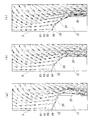
- 3A shows the flow velocity vector when the taper angle A of the inclined portion is 40 degrees
- FIG. 3B shows the flow velocity vector when the taper angle A is 100 degrees
- FIG. 3C shows the taper angle A.
- It is a distribution diagram which shows a flow velocity vector in case of 120 degrees.
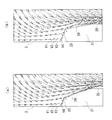
- FIG. 4A is a distribution diagram showing the flow velocity vector when the taper angle A of the inclined portion is 140 degrees
- FIG. 4B is a distribution diagram showing the flow velocity vector when the taper angle A is 160 degrees.
- FIG. 1 is a perspective view showing the external appearance of the camera device 100 according to the first embodiment.
- the camera device 100 includes a camera body 1, a lens barrel 2, a lens 3, and the like.
- the camera body 1 has a box-like shape having a hole communicating with the inside of the lens barrel 2, and houses a detector, a filter, and the like (not shown) therein.
- the lens barrel 2 has a tubular shape and supports an optical system arranged inside, and a lens 3 is fitted in the front opening 2a.
- the lens barrel 2 has a frame portion 20 for holding the lens 3.
- the lens 3 is, for example, an aspherical lens, but is not limited to this and may be a spherical lens or the like.
- the camera device 100 is, for example, an infrared camera, but is not limited to this, and may be a visible light imaging camera or the like.
- FIG. 2 is a sectional view of the front end portion of the camera device 100.
- the surface side of the lens 3 is exposed to the outside air and is exposed to the external environment such as wind and rain.
- An outer edge portion on the front surface side of the lens 3 exposed to the outside air is covered with a flange 21 of the frame portion 20 of the lens barrel 2.
- the lens barrel 2 is provided with a frame portion 20 for holding the lens 3 so as to fit inside the opening hole on the front end side, but the frame portion 20 and the lens barrel 2 are integrally formed. Good.
- the frame portion 20 of the lens barrel 2 has a flange 21 that covers the outer edge portion on the front surface side of the lens 3, and the light shielding portion 23 is formed on the inner peripheral portion of the inner edge portion 22.
- the light shielding portion 23 has a taper shape that is inclined with respect to the optical axis direction, and has a larger diameter toward the front end.
- the light blocking portion 23 functions to block infrared rays or light rays from an angle larger than the taper angle.
- An inclined portion 24 is formed on the inner edge portion 22 of the flange 21 so as to be continuous with the outer peripheral portion of the light shielding portion 23.
- the inclined portion 24 has a taper shape whose diameter increases toward the front end. As shown in FIG. 2, the taper angle A of the inclined portion 24 is larger than the taper angle of the light shielding portion 23, and more specifically, it is set to 120 degrees or more.
- the taper angle A of the inclined portion 24 is preferably set to 160 degrees or less. Details of setting the taper angle A of the inclined portion 24 will be described later.
- the flange 21 has a front end surface 25 that is continuous with the outer peripheral portion of the inclined portion 24 and extends outward.
- the thickness t of the flange 21 at the front end face 25 is set so as to have sufficient strength and rigidity to hold the lens 3.
- the thickness of the flange 21 is smaller than the thickness t of the front end face 25 in the light shielding portion 23 and the inclined portion 24.
- the inclined portion 24 and the front end surface 25 of the flange 21 shown in FIG. 2 are formed substantially at the front end of the lens barrel 2, but may be formed at a position recessed one step toward the camera body 1 side, or conversely on the front side. It may be formed at a position protruding further by one step. Further, the connection portion between the light shielding portion 23 and the inclined portion 24 and the connection portion between the inclined portion 24 and the front end face 25 may have corners or may be rounded and smoothly connected.
- the lens 3 has a concave surface portion 3a inside the light shielding portion 23 corresponding to the outer edge portion, the surface side of which is exposed to the outside air being concave toward the front.
- the lens 3 has a convex surface portion 3b, which is convex toward the front, inside the concave surface portion 3a.
- the lens 3 shown in FIG. 2 is formed as an aspherical lens. Further, as described above, the lens 3 may be a spherical lens or the like, and in this case, the concave surface portion 3a may not be formed.
- the camera device 100 is mounted on a vehicle or the like, receives wind from the front while the vehicle is traveling, and causes a wind flow on the front surface side of the lens 3. If there is a portion on the surface side of the lens 3 where the flow velocity is slow, water droplets tend to adhere to that portion, and the change in the flow velocity on the surface side of the lens 3 depending on the taper angle A of the inclined portion 24 will be examined.
- 3A shows the flow velocity vector when the taper angle A of the inclined portion 24 is 40 degrees
- FIG. 3B shows the flow velocity vector when the taper angle A is 100 degrees
- 3C shows the taper angle. It is a distribution diagram which shows a flow velocity vector in case of 120 degrees.
- 3A to 3C show flow velocity vectors generated when the camera device 100 receives wind from the front with a wind velocity of 16.67 m/s (corresponding to 60 km/h).
- Each arrow shown in FIGS. 3(a) to 3(c) is a flow velocity vector at that position, and indicates that a wind having a wind speed corresponding to the length of the arrow blows in the direction of the arrow.
- the flow velocity vectors V1 to V4 are flow velocity vectors inside the light shielding portion 23 corresponding to the outer edge portion of the lens 3.
- the flow velocity of V2 is smaller than the flow velocity vector V1
- the flow velocity of V3 is smaller than the flow velocity vector V2.
- the flow velocities of the flow velocity vectors V1, V2, and V3 in FIG. 3B are larger than the flow velocities of the flow velocity vectors V1, V2, and V3 in FIG. 3A, respectively.
- the flow velocity vectors V1, V2 and V3 near the lens 3 become slightly larger in the case of FIG. 3(b) than in FIG. 3(a).
- the flow velocities of the flow velocity vectors V1, V2, and V3 in FIG. 3C are respectively larger than the flow velocities of the flow velocity vectors V1, V2, and V3 in FIG. 3B. Therefore, compared to FIG. 3A, in the case of FIG. 3C, the flow velocity vectors V1, V2, and V3 near the lens 3 are further increased, and the improvement can be clearly understood.
- the flow velocity vector V4 is slightly larger in the case of FIG. 3(b) than in the case of FIG. 3(a). In contrast to FIG. 3A, the flow velocity vector V4 is further increased in the case of FIG. 3C, and the improvement can be clearly understood. From these, in the case where the taper angle A of the inclined portion 24 shown in FIG. 3(a) is 40 degrees, the case shown in FIG. 3(c) is larger than the case where the taper angle A shown in FIG. 3(b) is 100 degrees. When the taper angle A shown in (4) is 120 degrees, the flow velocity vector becomes clearly larger, and water droplets are less likely to adhere to the surface side of the lens 3.
- FIG. 4A is a flow velocity vector when the taper angle A of the inclined portion 24 is 140 degrees
- FIG. 4B is a distribution diagram showing the flow velocity vector when the taper angle A is 160 degrees.
- FIG. 4A and FIG. 4B are flow velocity vectors generated when the camera device 100 receives wind from the front with a wind velocity of 16.67 m/s. Is represented. Looking at the flow velocity vectors V1 to V4 shown in FIGS. 3(c), 4(a) and 4(b), the flow velocity vectors V1 to V4 are not significantly changed in FIGS. 3(c), 4(a) and 4(b). You can see that there is no.
- the flow velocity vector is about the same as when the taper angle A is 120 degrees. Further, the improvement can be clearly understood when the taper angle A is 120 degrees, 140 degrees and 160 degrees as compared with the case where the taper angle A of the inclined portion 24 shown in FIG. 3B is 100 degrees.
- the height of the light shielding portion 23 in FIG. 4(b) is set higher than the height of the light shielding portion 23 in FIG. 4(a). This is because when the height of the light shielding portion 23 in FIG. 4(b) is made equal to the height of the light shielding portion 23 in FIG.
- the taper angle A of the inclined portion 24 is 160 degrees, and therefore the diameter of the inclined portion 24 is small. This is because the dimension in the direction becomes large, the thickness t of the flange 21 becomes thin, the rigidity decreases, and the manufacturability decreases.
- the taper angle A of the inclined portion 24 is set to 120 degrees or more, in the camera device 100, the flow velocity is clearly increased inside the light shielding portion 23 that is the outer edge portion of the lens 3, and the adhesion of water droplets is suppressed.
- the thickness t of the front end surface 25 of the flange 21 is constant, and in each case, The strength and rigidity of the flange 21 can be secured, and the manufacturability is also good.
- setting the taper angle A of the inclined portion 24 to 180 degrees means that the inclined portion 24 is not provided, and the flow velocity decreases and water droplets easily adhere.
- the taper angle A of the inclined portion 24 is set to 120 degrees. As described above, by setting the angle to 160 degrees or less, the camera device 100 can suppress the attachment of water droplets.
- FIG. 5 is a distribution diagram showing the flow velocity vector when the thickness of the flange 21 is thin and the taper angle of the inclined portion 24 is 160 degrees.
- the height of the light shielding portion 23 shown in FIG. 5 is the same as that of the case shown in FIG. 4A, and the taper angle of the inclined portion 24 is 160 degrees.
- the flow velocity vectors V1 to V4 are substantially the same as those in FIG. 4B, and the flow velocity is clearly increased inside the light shielding portion 23, which is the outer edge portion of the lens 3, and water droplet adhesion is suppressed. can do.
- the case shown in FIG. 5 tends to be inferior in rigidity, strength, and manufacturability to the case shown in FIG. 4B because the thickness of the flange 21 is thin.
- the lens 3 when the lens 3 is an aspherical lens as described above, the lens 3 has the concave surface portion 3a inside the light shielding portion 23 corresponding to the outer edge portion of the lens 3.
- the concave surface portion 3a is provided, so that the concave surface portion 3a and the light shielding portion are provided at the connection portion between the concave surface portion 3a and the light shielding portion 23.
- the angle formed with 23 becomes large.
- FIG. 6 is a schematic diagram for explaining the embossing process provided on the surface of the flange 21.
- the front surface of the flange 21 is shown by the light shielding portion 23, the inclined portion 24 and the front end surface 25.
- the contact angle of water droplets changes, which increases the distance from the interface of the center of gravity of the water drop due to surface tension, and enhances drainage downward due to gravity, and Drainage of water drops is enhanced.
- the water drops on the surface of the flange 21 are easily removed by the wind, the flow of the wind is improved as a whole, and the adhesion of the water drops on the lens 3 is suppressed.
- the light-shielding portion 23 of the flange 21 is a surface continuous with the surface of the lens 3, and the surface of the light-shielding portion 23 is formed in a textured shape, so that the attachment of water droplets on the lens 3 is further suppressed.
- the lens 3 is an aspherical lens and the inclined portion 24 is provided, the textured shape of the surface of the flange 21 makes it easier for water droplets to be removed by the wind, and the flow of the wind as a whole. And the adhesion of water droplets on the lens 3 is suppressed.
- the lens 3 is an aspherical lens
- the inclined portion 24 is not provided, and the light shielding portion 23 is continuous with the front end surface 25, water droplets are likely to stay on the concave surface portion 3 a of the lens 3. Tends to become.
- the surface of the light shielding portion 23 and the front end surface 25 in a grain shape, the water droplets on the surface of the flange 21 are easily removed by the wind, the flow of the wind is improved as a whole, and the lens Adhesion of water droplets in 3 is suppressed.
- Fig. 7 is a chart showing the results of visual inspection of the drainage condition of raindrops with and without wrinkles. Water droplets and wind were actually blown onto the prototypes such as the lens barrel 2 and the lens 3, and the inspection was carried out in five stages. When the surface of the flange 21 was embossed, the water drop drainage condition was “good” when the taper angle A of the inclined portion 24 was 120 degrees and 160 degrees, and “very good” was obtained at 140 degrees. ..
- the water drop drainage status was “normal” when the taper angle A was 120 degrees and 160 degrees, and “good” when 140 degrees.
- the surface of the flange 21 is provided with a texture, the drainage condition is improved as compared with the case where the texture is not provided.
- the water repellency of the water drops is enhanced, and the drainage of the water drops is improved.
- the camera device 100 includes the lens 3 exposed to the outside air, and the lens barrel 2 having the flange 21 that covers the outer edge portion of the lens 3.
- the inner edge portion 22 of the flange 21 is formed with a tapered inclined portion 24 having a diameter increasing toward the front end.
- the taper angle A of the inclined portion 24 is 120 degrees or more.
- the taper angle A is 160 degrees or less.
- the camera device 100 can suppress the attachment of water droplets to the lens 3 and can secure the thickness of the flange 21.
- the front surface of the flange 21 is formed in a grain shape. Therefore, in the camera device 100, the water droplets on the surface of the flange 21 are easily removed by the wind, the flow of the wind is improved as a whole, and the adhesion of the water droplets on the lens 3 is suppressed.
- the lens 3 is an aspherical lens.
- the angle formed by the concave surface portion 3a and the light shielding portion 23 at the outer edge portion of the lens 3 becomes large, and the flow velocity of the wind at the connecting portion between the concave surface portion 3a and the light shielding portion 23 becomes high.
- the camera device 100 can increase the flow velocity of the wind at the outer edge portion of the lens 3.
- a light shielding portion 23 that is inclined with respect to the optical axis direction is formed inside the inclined portion 24, and the surface of the light shielding portion 23 is formed in a grain shape.
- the camera device 100 can have a light-shielding property in the lens 3, and since the surface of the light-shielding portion 23 is formed in the textured shape, the attachment of water droplets on the lens 3 is further suppressed.
- the present invention relates to a camera device mounted on a vehicle, for example.
Landscapes
- Physics & Mathematics (AREA)
- General Physics & Mathematics (AREA)
- Optics & Photonics (AREA)
- Studio Devices (AREA)
Abstract
カメラ装置は、外気に露出するレンズ(3)と、レンズ(3)の外縁部を覆うフランジ(21)を有する鏡筒(2)と、を備える。フランジ(21)の内縁部(22)に前端に向かうにつれて大径となるテーパ状の傾斜部(24)が形成されている。傾斜部(24)のテーパ角Aが120度以上である。
Description
本発明は、例えば車両に搭載されるカメラ装置に関する。
例えば、車両に搭載されるカメラ装置は、車両の前方や後方等の車両周囲を時間的に連続して撮影し、映像を記録する。カメラ装置は車両の内側や外側に取り付けられるが、車外に設けられたカメラ装置は風雨等の外部環境に曝される。
特許文献1には、第1レンズを収納支持する鏡筒の第1段部と第1レンズの端部との間に第1の弾性シーリング部材を配設し、第2レンズの端面にも、カメラ内部からの水分の浸透を防ぐ第2の弾性シーリング部材を配設したカメラ装置が開示されている。
また特許文献2には、鏡筒と、鏡筒から前方凸面の一部が前方に突き出た状態で保持されるレンズと、鏡筒に固定されるとともにレンズに固定される環状の押え部材とを備えるカメラ装置が開示されている。押え部材は、前方表面に内周端から外周端にかけて溝が形成されている。
特許文献1に記載のカメラ装置では、第1および第2の弾性シーリングによって、簡便且つ適切に密封可能としてレンズ内部の結露または曇りの発生を抑制できるが、外部から降りかかる雨水による水滴がレンズに付着することについては考慮されていない。とくに赤外線カメラ装置では、外気に露出するレンズに水滴が付着すると、赤外線の透過の妨げとなりカメラ性能が著しく劣化してしまうという問題点があった。
特許文献2に記載のカメラ装置では、押え部材に形成された溝は、水を排出する通路となるが、溝部分や、溝と溝との間の凸条部分に付着した水滴の排出が促進されるものではなかった。
本発明は、斯かる事情に鑑みてなされたものであり、その目的とするところは、外気に露出するレンズへの水滴の付着を抑制することができるカメラ装置を提供することにある。
本実施形態のある態様のカメラ装置は、外気に露出するレンズと、前記レンズの外縁部を覆うフランジを有する鏡筒と、を備えるカメラ装置において、前記フランジの内縁部に前端に向かうにつれて大径となるテーパ状の傾斜部が形成されており、前記傾斜部のテーパ角が120度以上であることを特徴とする。
本発明によれば、カメラ装置は外気に露出するレンズへの水滴の付着を抑制することができる。
以下、本発明を好適な実施の形態をもとに図1から図7を参照しながら説明する。各図面に示される同一または同等の構成要素、部材には、同一の符号を付するものとし、適宜重複した説明は省略する。また、各図面における部材の寸法は、理解を容易にするために適宜拡大、縮小して示される。また、各図面において実施の形態を説明する上で重要ではない部材の一部は省略して表示する。
(実施形態1)
図1は、実施形態1に係るカメラ装置100の外観を示す斜視図である。カメラ装置100は、カメラ本体1、鏡筒2およびレンズ3等を備える。カメラ本体1は、鏡筒2内に通じる孔を設けた箱状であり、内部に図示しない検出器やフィルタ等を収容してなる。鏡筒2は、筒状であり内部に配置される光学系を支持し、前面の開口部2aにはレンズ3が嵌められている。鏡筒2は、レンズ3を保持するための枠部20を有している。レンズ3は、例えば非球面レンズであるが、これに限られず球面レンズ等であってもよい。また、カメラ装置100は、例えば赤外線カメラであるが、これに限られず、可視光撮像カメラなどであってもよい。
図1は、実施形態1に係るカメラ装置100の外観を示す斜視図である。カメラ装置100は、カメラ本体1、鏡筒2およびレンズ3等を備える。カメラ本体1は、鏡筒2内に通じる孔を設けた箱状であり、内部に図示しない検出器やフィルタ等を収容してなる。鏡筒2は、筒状であり内部に配置される光学系を支持し、前面の開口部2aにはレンズ3が嵌められている。鏡筒2は、レンズ3を保持するための枠部20を有している。レンズ3は、例えば非球面レンズであるが、これに限られず球面レンズ等であってもよい。また、カメラ装置100は、例えば赤外線カメラであるが、これに限られず、可視光撮像カメラなどであってもよい。
図2は、カメラ装置100の前端部分の断面図である。レンズ3は、表面側が外気に露出しており、風雨等の外部環境に曝される。外気に露出するレンズ3の表面側の外縁部分は、鏡筒2が有する枠部20のフランジ21によって覆われている。鏡筒2は、前端側の開口孔の内側に嵌め合わせるようにして、レンズ3を保持する枠部20が設けられているが、枠部20と鏡筒2とが一体的に形成されていてもよい。
鏡筒2における枠部20は、レンズ3の表面側の外縁部分を覆うフランジ21を有しており、内縁部22の内周部分に遮光部23が形成されている。遮光部23は、光軸方向に対して傾斜するテーパ状であり、前端に向かうにつれて大径となる。遮光部23は、テーパ角よりも大きい角度からの赤外線または光線を遮るように機能する。
フランジ21の内縁部22には、遮光部23の外周部分に連続して傾斜部24が形成されている。傾斜部24は、前端に向かうにつれて大径となるテーパ状である。図2に示すように傾斜部24のテーパ角Aは、遮光部23のテーパ角よりも大きく、より具体的には120度以上に設定している。また、傾斜部24のテーパ角Aは、160度以下に設定することが好ましい。傾斜部24のテーパ角Aの設定についての詳細は後述する。
フランジ21は、傾斜部24の外周部分に連続し、外側に延びる前端面25を有している。前端面25でのフランジ21の厚みtは、レンズ3を保持するに十分な強度および剛性を持つように設定される。フランジ21の厚みは、遮光部23および傾斜部24では前端面25の厚みtよりも薄くなる。遮光部23、傾斜部24および前端面25での厚みが薄くなると、剛性が低下して変形したり、強度が低下して割れが生じたり、さらには製造性が悪くなる。
図2に示すフランジ21の傾斜部24および前端面25は、鏡筒2のほぼ前端に形成されているが、カメラ本体1側に一段窪んだ位置に形成されても良いし、逆に前方側に一段突出した位置に形成されていても良い。また、遮光部23と傾斜部24との接続箇所、および傾斜部24と前端面25との接続箇所は、角が生じていても良いし、丸みを帯びて滑らかに接続していても良い。
レンズ3は、外縁部分にあたる遮光部23の内側において、外気に露出する表面側が前方に対して凹状となる凹面部3aを有する。レンズ3は、凹面部3aに連続する内側に、前方に対して凸状となる凸面部3bを有する。図2に示すレンズ3は、非球面レンズとして形成されている。また、上述のようにレンズ3は球面レンズ等であってもよく、この場合、凹面部3aが形成されない構成となることがある。
次に、傾斜部24のテーパ角Aの変化によるレンズ3の表面側における流速および水滴の付着について説明する。カメラ装置100は、車両等に搭載され、該車両の走行中に前方から風を受けて、レンズ3の表面側に風の流れが生じる。レンズ3の表面側において流速が遅い箇所があると、該箇所に水滴が付着し易くなり、傾斜部24のテーパ角Aに応じたレンズ3の表面側における流速の変化を検討する。図3(a)は傾斜部24のテーパ角Aが40度の場合の流速ベクトルを、図3(b)はテーパ角Aが100度の場合の流速ベクトルを、図3(c)はテーパ角が120度の場合の流速ベクトルを示す分布図である。図3(a)~図3(c)ではカメラ装置100が前方から風速16.67m/s(60km/h相当)の風を受けたときに生じる流速ベクトルを表している。図3(a)~図3(c)に示す各矢印は、その位置における流速ベクトルであり、矢印の方向に、矢印の長さに応じた風速の風が吹くことを示している。
図3(a)~図3(c)に示される流速ベクトルのうち、レンズ3に近く遮光部23に徐々に近づく位置にある流速ベクトルV1~V3、および流速ベクトルV3に対して前方側にレンズ3から遠ざかる位置にある流速ベクトルV4について説明する。流速ベクトルV1~V4は、レンズ3の外縁部分にあたる遮光部23の内側における流速ベクトルとなっている。
図3(a)~図3(c)において、流速ベクトルV1よりもV2の流速が、流速ベクトルV2よりもV3の流速が小さくなっている。これにより、レンズ3の近くでは、遮光部23に近い位置ほど、流速が低下し、水滴が吹き付けられたときに、水滴が流され難く、付着し易い傾向にある。
図3(a)における流速ベクトルV1、V2およびV3の流速よりも、図3(b)における流速ベクトルV1、V2およびV3の流速の方がそれぞれ大きい。これにより、図3(a)に対して、図3(b)の場合にレンズ3近くの流速ベクトルV1、V2およびV3がやや大きくなる。また、図3(b)における流速ベクトルV1、V2およびV3の流速よりも、図3(c)における流速ベクトルV1、V2およびV3の流速の方がそれぞれ大きい。したがって、図3(a)に対して、図3(c)の場合にレンズ3近くの流速ベクトルV1、V2およびV3が更に大きくなり、改善が明確に把握できる。
また、流速ベクトルV4についても、図3(a)に対して、図3(b)の場合にやや大きくなる。図3(a)に対して、図3(c)の場合に流速ベクトルV4が更に大きくなり、改善が明確に把握できる。これらのことから、図3(a)に示す傾斜部24のテーパ角Aが40度の場合に対して、図3(b)に示すテーパ角Aが100度の場合よりも図3(c)に示すテーパ角Aが120度の場合の方が流速ベクトルが明確に大きくなり、水滴がレンズ3の表面側に付着し難くなる。
図4(a)は傾斜部24のテーパ角Aが140度の場合の流速ベクトルを、図4(b)はテーパ角Aが160度の場合の流速ベクトルを示す分布図である。図4(a)および図4(b)は、図3(a)~図3(c)と同様に、カメラ装置100が前方から風速16.67m/sの風を受けたときに生じる流速ベクトルを表している。図3(c)、図4(a)および図4(b)に示される流速ベクトルV1~V4を見ると、図3(c)、図4(a)および図4(b)において、あまり変化がないことがわかる。これにより、傾斜部24のテーパ角Aが140度および160度の場合にも、テーパ角Aが120度の場合と同程度の流速ベクトルを有することがわかる。更に図3(b)に示す傾斜部24のテーパ角Aが100度の場合に比べて、テーパ角Aが120度、140度および160度の場合に改善が明確に把握できる。尚、図4(b)における遮光部23の高さは、図4(a)における遮光部23の高さよりも高くしてある。これは、図4(b)における遮光部23の高さを図4(a)における遮光部23の高さと同等とすると、傾斜部24のテーパ角Aが160度のため、傾斜部24の径方向の寸法が大きくなり、フランジ21の厚みtが薄くなって剛性が低下し、また製造性が低下してしまうためである。
したがって、傾斜部24のテーパ角Aを120度以上とすることで、カメラ装置100は、レンズ3の外縁部分にあたる遮光部23の内側において、流速が明確に大きくなり、水滴の付着を抑制することができる。
図3(a)~図3(c)、並びに、図4(a)および図4(b)に示した各ケースでは、フランジ21の前端面25における厚みtを一定としており、各ケースにおいて、フランジ21部分の強度および剛性を確保できており、製造性も良好となる。例えば、傾斜部24のテーパ角Aを180度とすることは、傾斜部24を設けないことを意味しており、流速が低下して、水滴が付着し易くなってしまう。
したがって、上述のとおりテーパ角Aを40度、100度以降20度ごとに、120度、140度、160度および180度とした場合を検討した結果から、傾斜部24のテーパ角Aを120度以上、160度以下と設定することで、カメラ装置100は、水滴の付着を抑制することができる。
図5はフランジ21の厚みが薄く、傾斜部24のテーパ角が160度の場合の流速ベクトルを示す分布図である。図5に示す遮光部23の高さは図4(a)に示したケースと同等とし、傾斜部24のテーパ角を160度としている。図5に示す場合でも、流速ベクトルV1~V4は、図4(b)と同程度であり、レンズ3の外縁部分にあたる遮光部23の内側において、流速が明確に大きくなり、水滴の付着を抑制することができる。しかし、図5に示すケースでは、フランジ21の厚みが薄くなることから、図4(b)に示すケースよりも剛性、強度および製造性の面で劣る傾向にある。
また、レンズ3は、上述のように非球面レンズである場合に、レンズ3の外縁部分にあたる遮光部23の内側に凹面部3aを有している。前方に対して凸となる球面レンズが遮光部23に接続される場合と比較すると、凹面部3aが設けられることにより、凹面部3aと遮光部23との接続部分において、凹面部3aと遮光部23とがなす角度が大きくなる。凹面部3aと遮光部23とがなす角度が大きくなることで、凹面部3aと遮光部23との接続部分における風の流速が速くなり、水滴の付着を抑制することができる。
(実施形態2)
図6は、フランジ21の表面に設けるシボ加工について説明するための模式図である。フランジ21の前方側の表面は、遮光部23、傾斜部24および前端面25に表われる。遮光部23、傾斜部24および前端面25の少なくともいずれか一つに対して、または二つ以上の任意の組合せに対して、シボ加工またはシボ塗装を施し、表面がシボ形状となるように形成されている。
図6は、フランジ21の表面に設けるシボ加工について説明するための模式図である。フランジ21の前方側の表面は、遮光部23、傾斜部24および前端面25に表われる。遮光部23、傾斜部24および前端面25の少なくともいずれか一つに対して、または二つ以上の任意の組合せに対して、シボ加工またはシボ塗装を施し、表面がシボ形状となるように形成されている。
フランジ21の表面にシボを設けることによって、水滴の接触角が変わり、これによって表面張力による水玉の重心の界面からの距離が長くなり、重力による下方への排水性が高まり、フランジ21の表面における水滴の排水性が高まる。フランジ21の表面における水滴が風によって除去され易くなり、風の流れが全体的に良くなって、レンズ3における水滴の付着が抑制される。フランジ21において遮光部23はレンズ3の表面に連続する面となっており、遮光部23の表面がシボ形状に形成されていることで、レンズ3における水滴の付着がより抑制される。
実施形態1において説明したように、レンズ3が非球面レンズであり、傾斜部24が設けられる場合には、フランジ21の表面のシボ形状によって水滴が風によって除去され易くなり、風の流れが全体的に良くなり、レンズ3における水滴の付着が抑制される。
これに対して、レンズ3が非球面レンズであり、傾斜部24が設けられておらず、遮光部23が前端面25に連続する場合には、水滴がレンズ3の凹面部3aに滞留し易くなる傾向にある。この場合でも、遮光部23や前端面25の表面がシボ形状に形成されることによって、フランジ21の表面での水滴が風によって除去され易くなり、風の流れが全体的に良くなって、レンズ3における水滴の付着が抑制される。
図7は、シボの有無による雨滴の排水状況を目視で検査した結果を示す図表である。鏡筒2およびレンズ3等の試作品に実際に水滴および風を吹きつけて、5段階により検査を実施した。フランジ21の表面にシボを設けたとき、傾斜部24のテーパ角Aが120度および160度で水滴の排水状況は「良い」となり、140度で「非常に良い」との結果が得られた。
一方、フランジ21の表面にシボを設けていないとき、テーパ角Aが120度および160度で水滴の排水状況は「普通」となり、140度で「良い」との結果が得られた。フランジ21の表面にシボを設けた場合、シボを設けなかった場合と比較すると、排水状況が良くなる。また、シボ塗装の材料によっては、水滴の撥水効果が高まり、水滴の排水性が良くなる。
次に、上述の各実施形態に係るカメラ装置100の特徴を説明する。
実施形態に係るカメラ装置100は、外気に露出するレンズ3と、レンズ3の外縁部を覆うフランジ21を有する鏡筒2と、を備える。フランジ21の内縁部22に前端に向かうにつれて大径となるテーパ状の傾斜部24が形成されている。傾斜部24のテーパ角Aが120度以上である。これにより、カメラ装置100は、外気に露出するレンズ3への水滴の付着を抑制することができる。
実施形態に係るカメラ装置100は、外気に露出するレンズ3と、レンズ3の外縁部を覆うフランジ21を有する鏡筒2と、を備える。フランジ21の内縁部22に前端に向かうにつれて大径となるテーパ状の傾斜部24が形成されている。傾斜部24のテーパ角Aが120度以上である。これにより、カメラ装置100は、外気に露出するレンズ3への水滴の付着を抑制することができる。
また、テーパ角Aが160度以下である。これにより、カメラ装置100は、レンズ3への水滴の付着を抑制することができ、フランジ21の厚みを確保することができる。
また、フランジ21の前方側の表面には、シボ形状に形成されている。これにより、カメラ装置100は、フランジ21の表面における水滴が風によって除去され易くなり、風の流れが全体的に良くなって、レンズ3における水滴の付着が抑制される。
また、レンズ3は非球面レンズである。レンズ3が非球面レンズである場合、レンズ3の外縁部分における凹面部3aと遮光部23とがなす角度が大きくなり、凹面部3aと遮光部23との接続部分における風の流速が速くなる。これにより、カメラ装置100は、レンズ3の外縁部分での風の流速を速くすることができる。
また、傾斜部24の内側に光軸方向に対して傾斜する遮光部23が形成されており、遮光部23の表面がシボ形状に形成されている。これにより、カメラ装置100は、レンズ3での遮光性を持たせることができ、遮光部23の表面がシボ形状に形成されていることによって、レンズ3における水滴の付着がより抑制される。
以上、本発明の実施の形態をもとに説明した。これらの実施の形態は例示であり、いろいろな変形および変更が本発明の特許請求範囲内で可能なこと、またそうした変形例および変更も本発明の特許請求の範囲にあることは当業者に理解されるところである。従って、本明細書での記述および図面は限定的ではなく例証的に扱われるべきものである。
本発明は、例えば車両に搭載されるカメラ装置に関する。
2 鏡筒、 21 フランジ、 22 内縁部、 23 遮光部、 24 傾斜部、
3 レンズ、 100 カメラ装置。
3 レンズ、 100 カメラ装置。
Claims (5)
- 外気に露出するレンズと、
前記レンズの外縁部を覆うフランジを有する鏡筒と、を備えるカメラ装置において、
前記フランジの内縁部に前端に向かうにつれて大径となるテーパ状の傾斜部が形成されており、前記傾斜部のテーパ角が120度以上であることを特徴とするカメラ装置。 - 前記テーパ角が160度以下であることを特徴とする請求項1に記載のカメラ装置。
- 前記フランジの前方側の表面がシボ形状に形成されていることを特徴とする請求項1または2に記載のカメラ装置。
- 前記レンズは非球面レンズであることを特徴とする請求項1から3のいずれか1項に記載のカメラ装置。
- 前記傾斜部の内側に光軸方向に対して傾斜する遮光部が形成されており、
前記遮光部の表面がシボ形状に形成されていることを特徴とする請求項1から4のいずれか1項に記載のカメラ装置。
Applications Claiming Priority (4)
| Application Number | Priority Date | Filing Date | Title |
|---|---|---|---|
| JP2018-220389 | 2018-11-26 | ||
| JP2018220389A JP2020086122A (ja) | 2018-11-26 | 2018-11-26 | カメラ装置 |
| JP2018220390A JP2020086123A (ja) | 2018-11-26 | 2018-11-26 | カメラ装置 |
| JP2018-220390 | 2018-11-26 |
Publications (1)
| Publication Number | Publication Date |
|---|---|
| WO2020110416A1 true WO2020110416A1 (ja) | 2020-06-04 |
Family
ID=70852793
Family Applications (1)
| Application Number | Title | Priority Date | Filing Date |
|---|---|---|---|
| PCT/JP2019/035437 Ceased WO2020110416A1 (ja) | 2018-11-26 | 2019-09-10 | カメラ装置 |
Country Status (1)
| Country | Link |
|---|---|
| WO (1) | WO2020110416A1 (ja) |
Cited By (2)
| Publication number | Priority date | Publication date | Assignee | Title |
|---|---|---|---|---|
| WO2024135196A1 (ja) * | 2022-12-22 | 2024-06-27 | 日立Astemo株式会社 | カメラ装置 |
| JP2025005531A (ja) * | 2023-06-28 | 2025-01-17 | 株式会社棚澤八光社 | 光学素子の周辺構造、光学装置および樹脂成形用型 |
Citations (8)
| Publication number | Priority date | Publication date | Assignee | Title |
|---|---|---|---|---|
| JPS5843407A (ja) * | 1981-09-08 | 1983-03-14 | Olympus Optical Co Ltd | レンズ保持機構 |
| JPH11271586A (ja) * | 1998-03-25 | 1999-10-08 | Fuji Photo Optical Co Ltd | レンズの支持構造 |
| JP2004102234A (ja) * | 2002-07-18 | 2004-04-02 | Konica Minolta Holdings Inc | 撮像レンズ,撮像ユニット及びこれを備える携帯端末 |
| JP2008151820A (ja) * | 2006-12-14 | 2008-07-03 | Pentax Corp | レンズ鏡筒 |
| JP2009025591A (ja) * | 2007-07-20 | 2009-02-05 | Hoya Corp | レンズの調芯及び固定方法 |
| JP2012173366A (ja) * | 2011-02-17 | 2012-09-10 | Tamron Co Ltd | レンズ保持構造 |
| US20190179100A1 (en) * | 2017-12-08 | 2019-06-13 | AAC Technologies Pte. Ltd. | Camera lens |
| JP2019164253A (ja) * | 2018-03-20 | 2019-09-26 | カンタツ株式会社 | 撮像レンズおよびカメラモジュール |
-
2019
- 2019-09-10 WO PCT/JP2019/035437 patent/WO2020110416A1/ja not_active Ceased
Patent Citations (8)
| Publication number | Priority date | Publication date | Assignee | Title |
|---|---|---|---|---|
| JPS5843407A (ja) * | 1981-09-08 | 1983-03-14 | Olympus Optical Co Ltd | レンズ保持機構 |
| JPH11271586A (ja) * | 1998-03-25 | 1999-10-08 | Fuji Photo Optical Co Ltd | レンズの支持構造 |
| JP2004102234A (ja) * | 2002-07-18 | 2004-04-02 | Konica Minolta Holdings Inc | 撮像レンズ,撮像ユニット及びこれを備える携帯端末 |
| JP2008151820A (ja) * | 2006-12-14 | 2008-07-03 | Pentax Corp | レンズ鏡筒 |
| JP2009025591A (ja) * | 2007-07-20 | 2009-02-05 | Hoya Corp | レンズの調芯及び固定方法 |
| JP2012173366A (ja) * | 2011-02-17 | 2012-09-10 | Tamron Co Ltd | レンズ保持構造 |
| US20190179100A1 (en) * | 2017-12-08 | 2019-06-13 | AAC Technologies Pte. Ltd. | Camera lens |
| JP2019164253A (ja) * | 2018-03-20 | 2019-09-26 | カンタツ株式会社 | 撮像レンズおよびカメラモジュール |
Cited By (3)
| Publication number | Priority date | Publication date | Assignee | Title |
|---|---|---|---|---|
| WO2024135196A1 (ja) * | 2022-12-22 | 2024-06-27 | 日立Astemo株式会社 | カメラ装置 |
| JP2024089699A (ja) * | 2022-12-22 | 2024-07-04 | 日立Astemo株式会社 | カメラ装置 |
| JP2025005531A (ja) * | 2023-06-28 | 2025-01-17 | 株式会社棚澤八光社 | 光学素子の周辺構造、光学装置および樹脂成形用型 |
Similar Documents
| Publication | Publication Date | Title |
|---|---|---|
| CN104039610B (zh) | 摄像机系统、尤其用于车辆的摄像机系统 | |
| US8425058B2 (en) | Optical unit, image pickup device using the optical unit, and on-vehicle image display device using the image pickup device | |
| EP3526065B1 (fr) | Pare-brise d'aide a la conduite | |
| US20180361935A1 (en) | Imaging device | |
| JP2009265473A (ja) | レンズ、撮像レンズ及び撮像装置 | |
| TW201814391A (zh) | 汽車攝影鏡頭防止水珠遮鏡裝置 | |
| JP2006337691A (ja) | 結像光学系 | |
| JP2008148276A (ja) | 光学ユニット、前記光学ユニットを用いた撮像装置、ならびに前記撮像装置を用いた車両用画像表示装置 | |
| CN101990646A (zh) | 成像光学系统以及使用该成像光学系统的摄像装置 | |
| WO2020110416A1 (ja) | カメラ装置 | |
| JP6910184B2 (ja) | 広角レンズユニットおよび車載カメラ | |
| WO2019058742A1 (ja) | 膜付きレンズ、レンズユニットおよびカメラモジュール | |
| CN106061795A (zh) | 后方拍摄装置 | |
| JP2018100996A (ja) | レンズユニット | |
| JP2010060699A (ja) | レンズユニット、及び撮像装置 | |
| JP2020086122A (ja) | カメラ装置 | |
| JP2011221136A (ja) | 組合せレンズ、レンズユニット、撮像装置、及び組合せレンズの連結固定方法 | |
| JP2020086123A (ja) | カメラ装置 | |
| JP2013228745A (ja) | カメラカバー及びカメラ | |
| CN112799199A (zh) | 镜头 | |
| JP6568799B2 (ja) | レンズユニット、撮像装置、および車載カメラ | |
| JP2013134366A (ja) | カメラ装置 | |
| JP6899701B2 (ja) | レンズユニット、カメラモジュールおよび第1レンズの製造方法 | |
| JP5963066B2 (ja) | カメラ装置 | |
| JP2003175767A (ja) | 赤外線カメラ及び赤外線カメラ搭載車両 |
Legal Events
| Date | Code | Title | Description |
|---|---|---|---|
| 121 | Ep: the epo has been informed by wipo that ep was designated in this application |
Ref document number: 19890529 Country of ref document: EP Kind code of ref document: A1 |
|
| NENP | Non-entry into the national phase |
Ref country code: DE |
|
| 122 | Ep: pct application non-entry in european phase |
Ref document number: 19890529 Country of ref document: EP Kind code of ref document: A1 |