WO2020105729A1 - リチウムイオン二次電池用正極、リチウムイオン二次電池およびリチウムイオン二次電池用正極の製造方法 - Google Patents
リチウムイオン二次電池用正極、リチウムイオン二次電池およびリチウムイオン二次電池用正極の製造方法Info
- Publication number
- WO2020105729A1 WO2020105729A1 PCT/JP2019/045732 JP2019045732W WO2020105729A1 WO 2020105729 A1 WO2020105729 A1 WO 2020105729A1 JP 2019045732 W JP2019045732 W JP 2019045732W WO 2020105729 A1 WO2020105729 A1 WO 2020105729A1
- Authority
- WO
- WIPO (PCT)
- Prior art keywords
- active material
- particles
- electrode
- carbon nanotubes
- length
- Prior art date
- Legal status (The legal status is an assumption and is not a legal conclusion. Google has not performed a legal analysis and makes no representation as to the accuracy of the status listed.)
- Ceased
Links
Images



Classifications
-
- H—ELECTRICITY
- H01—ELECTRIC ELEMENTS
- H01M—PROCESSES OR MEANS, e.g. BATTERIES, FOR THE DIRECT CONVERSION OF CHEMICAL ENERGY INTO ELECTRICAL ENERGY
- H01M4/00—Electrodes
- H01M4/02—Electrodes composed of, or comprising, active material
- H01M4/13—Electrodes for accumulators with non-aqueous electrolyte, e.g. for lithium-accumulators; Processes of manufacture thereof
- H01M4/133—Electrodes based on carbonaceous material, e.g. graphite-intercalation compounds or CFx
-
- H—ELECTRICITY
- H01—ELECTRIC ELEMENTS
- H01M—PROCESSES OR MEANS, e.g. BATTERIES, FOR THE DIRECT CONVERSION OF CHEMICAL ENERGY INTO ELECTRICAL ENERGY
- H01M4/00—Electrodes
- H01M4/02—Electrodes composed of, or comprising, active material
- H01M4/62—Selection of inactive substances as ingredients for active masses, e.g. binders, fillers
- H01M4/624—Electric conductive fillers
- H01M4/625—Carbon or graphite
-
- C—CHEMISTRY; METALLURGY
- C01—INORGANIC CHEMISTRY
- C01B—NON-METALLIC ELEMENTS; COMPOUNDS THEREOF; METALLOIDS OR COMPOUNDS THEREOF NOT COVERED BY SUBCLASS C01C
- C01B32/00—Carbon; Compounds thereof
- C01B32/15—Nano-sized carbon materials
- C01B32/158—Carbon nanotubes
-
- C—CHEMISTRY; METALLURGY
- C01—INORGANIC CHEMISTRY
- C01B—NON-METALLIC ELEMENTS; COMPOUNDS THEREOF; METALLOIDS OR COMPOUNDS THEREOF NOT COVERED BY SUBCLASS C01C
- C01B32/00—Carbon; Compounds thereof
- C01B32/15—Nano-sized carbon materials
- C01B32/158—Carbon nanotubes
- C01B32/159—Carbon nanotubes single-walled
-
- C—CHEMISTRY; METALLURGY
- C01—INORGANIC CHEMISTRY
- C01B—NON-METALLIC ELEMENTS; COMPOUNDS THEREOF; METALLOIDS OR COMPOUNDS THEREOF NOT COVERED BY SUBCLASS C01C
- C01B32/00—Carbon; Compounds thereof
- C01B32/15—Nano-sized carbon materials
- C01B32/158—Carbon nanotubes
- C01B32/168—After-treatment
-
- H—ELECTRICITY
- H01—ELECTRIC ELEMENTS
- H01M—PROCESSES OR MEANS, e.g. BATTERIES, FOR THE DIRECT CONVERSION OF CHEMICAL ENERGY INTO ELECTRICAL ENERGY
- H01M10/00—Secondary cells; Manufacture thereof
- H01M10/05—Accumulators with non-aqueous electrolyte
- H01M10/052—Li-accumulators
- H01M10/0525—Rocking-chair batteries, i.e. batteries with lithium insertion or intercalation in both electrodes; Lithium-ion batteries
-
- H—ELECTRICITY
- H01—ELECTRIC ELEMENTS
- H01M—PROCESSES OR MEANS, e.g. BATTERIES, FOR THE DIRECT CONVERSION OF CHEMICAL ENERGY INTO ELECTRICAL ENERGY
- H01M4/00—Electrodes
- H01M4/02—Electrodes composed of, or comprising, active material
- H01M4/04—Processes of manufacture in general
- H01M4/0402—Methods of deposition of the material
- H01M4/0404—Methods of deposition of the material by coating on electrode collectors
-
- H—ELECTRICITY
- H01—ELECTRIC ELEMENTS
- H01M—PROCESSES OR MEANS, e.g. BATTERIES, FOR THE DIRECT CONVERSION OF CHEMICAL ENERGY INTO ELECTRICAL ENERGY
- H01M4/00—Electrodes
- H01M4/02—Electrodes composed of, or comprising, active material
- H01M4/13—Electrodes for accumulators with non-aqueous electrolyte, e.g. for lithium-accumulators; Processes of manufacture thereof
-
- H—ELECTRICITY
- H01—ELECTRIC ELEMENTS
- H01M—PROCESSES OR MEANS, e.g. BATTERIES, FOR THE DIRECT CONVERSION OF CHEMICAL ENERGY INTO ELECTRICAL ENERGY
- H01M4/00—Electrodes
- H01M4/02—Electrodes composed of, or comprising, active material
- H01M4/13—Electrodes for accumulators with non-aqueous electrolyte, e.g. for lithium-accumulators; Processes of manufacture thereof
- H01M4/139—Processes of manufacture
-
- H—ELECTRICITY
- H01—ELECTRIC ELEMENTS
- H01M—PROCESSES OR MEANS, e.g. BATTERIES, FOR THE DIRECT CONVERSION OF CHEMICAL ENERGY INTO ELECTRICAL ENERGY
- H01M4/00—Electrodes
- H01M4/02—Electrodes composed of, or comprising, active material
- H01M4/13—Electrodes for accumulators with non-aqueous electrolyte, e.g. for lithium-accumulators; Processes of manufacture thereof
- H01M4/139—Processes of manufacture
- H01M4/1393—Processes of manufacture of electrodes based on carbonaceous material, e.g. graphite-intercalation compounds or CFx
-
- H—ELECTRICITY
- H01—ELECTRIC ELEMENTS
- H01M—PROCESSES OR MEANS, e.g. BATTERIES, FOR THE DIRECT CONVERSION OF CHEMICAL ENERGY INTO ELECTRICAL ENERGY
- H01M4/00—Electrodes
- H01M4/02—Electrodes composed of, or comprising, active material
- H01M4/62—Selection of inactive substances as ingredients for active masses, e.g. binders, fillers
-
- B—PERFORMING OPERATIONS; TRANSPORTING
- B82—NANOTECHNOLOGY
- B82Y—SPECIFIC USES OR APPLICATIONS OF NANOSTRUCTURES; MEASUREMENT OR ANALYSIS OF NANOSTRUCTURES; MANUFACTURE OR TREATMENT OF NANOSTRUCTURES
- B82Y30/00—Nanotechnology for materials or surface science, e.g. nanocomposites
-
- H—ELECTRICITY
- H01—ELECTRIC ELEMENTS
- H01M—PROCESSES OR MEANS, e.g. BATTERIES, FOR THE DIRECT CONVERSION OF CHEMICAL ENERGY INTO ELECTRICAL ENERGY
- H01M4/00—Electrodes
- H01M4/02—Electrodes composed of, or comprising, active material
- H01M2004/021—Physical characteristics, e.g. porosity, surface area
-
- H—ELECTRICITY
- H01—ELECTRIC ELEMENTS
- H01M—PROCESSES OR MEANS, e.g. BATTERIES, FOR THE DIRECT CONVERSION OF CHEMICAL ENERGY INTO ELECTRICAL ENERGY
- H01M4/00—Electrodes
- H01M4/02—Electrodes composed of, or comprising, active material
- H01M2004/026—Electrodes composed of, or comprising, active material characterised by the polarity
- H01M2004/028—Positive electrodes
-
- Y—GENERAL TAGGING OF NEW TECHNOLOGICAL DEVELOPMENTS; GENERAL TAGGING OF CROSS-SECTIONAL TECHNOLOGIES SPANNING OVER SEVERAL SECTIONS OF THE IPC; TECHNICAL SUBJECTS COVERED BY FORMER USPC CROSS-REFERENCE ART COLLECTIONS [XRACs] AND DIGESTS
- Y02—TECHNOLOGIES OR APPLICATIONS FOR MITIGATION OR ADAPTATION AGAINST CLIMATE CHANGE
- Y02E—REDUCTION OF GREENHOUSE GAS [GHG] EMISSIONS, RELATED TO ENERGY GENERATION, TRANSMISSION OR DISTRIBUTION
- Y02E60/00—Enabling technologies; Technologies with a potential or indirect contribution to GHG emissions mitigation
- Y02E60/10—Energy storage using batteries
Definitions
- the present invention relates to a positive electrode for a lithium ion secondary battery, a lithium ion secondary battery, and a method for manufacturing a positive electrode for a lithium ion secondary battery.
- the present application claims priority based on Japanese Patent Application No. 2018-219707 filed in Japan on November 22, 2018, and the content thereof is incorporated herein.
- a lithium-ion secondary battery is composed of a positive electrode, a negative electrode, an electrolytic solution, and a separator, and in order to increase the output of the battery, it is essential to reduce the resistance of its constituent elements. Since the main targets for lowering the resistance are the positive electrode and the negative electrode, various studies have been made on materials such as the electrode active material particle powder, the conductive material, the binder, and the current collector constituting the electrode.
- Patent Document 1 discloses that a fluorine-containing cyclic carbonate is contained in an amount of 15 to 40% by volume, a fluorine-containing chain carbonate and / or a fluorine-containing chain ether is contained in a total amount of 45 to 85% by volume, and a fluorine-free cyclic carbonate is contained.
- a lithium ion secondary battery comprising a non-aqueous electrolytic solution containing a lithium salt and a positive electrode containing a complex oxide containing manganese as an active material in a non-aqueous solvent having a carbonate content of 10% by volume or less.
- a positive electrode slurry containing a binder such as polyvinylidene fluoride (PVDF) is applied to one surface of a current collector made of an aluminum foil by a bar coater, and the current collector coated with the positive electrode slurry is dried. Then, the obtained sheet-shaped positive electrode is compression-molded using a roll press and then dried to obtain a positive electrode.
- PVDF polyvinylidene fluoride
- Patent Document 2 discloses a thin film electrode in which a Prussian blue type cyano crosslinked metal complex as a positive electrode active material is electrolytically deposited on the metal surface of a positive electrode current collector.
- Non-Patent Document 1 includes a carbon nanotube having a fiber diameter of 11 nm and a fiber length of 370 ⁇ m, and a non-woven electrode obtained by ultrasonically dispersing electrode active material particle powder and a solvent, filtering and drying. ing.
- Patent Document 1 since an insulating binder is used in the substance forming the electrode, it is unavoidable to increase the resistance of the electrode, and in the case where the binder is not used, it becomes a collector. There is a problem that the adhesion of the active material particles is insufficient. Further, in the technique of Patent Document 2, there is a problem that the cost for electrolytic deposition is high, and since the thin film shape cannot provide a large amount of active material on the electrode, the energy density cannot be increased. there were.
- the technique of Non-Patent Document 3 has a problem that it is difficult to mass-produce a large-area electrode because the cake is dried on the filter of the filtering device and is collected as an electrode. .. Further, in the case of joining the non-woven electrode obtained for ensuring the conductivity and the metal support, even if they are mechanically pressure-bonded to each other, the joining strength cannot be sufficiently obtained. Therefore, it cannot be said that sufficient battery characteristics are obtained.
- An object of the present invention is to achieve both excellent electrical conductivity and adhesion of an electrode active material, and to improve battery characteristics as compared with conventional positive electrodes for lithium ion secondary batteries, lithium ion secondary batteries and lithium ions. It is to provide a method for manufacturing a positive electrode for a secondary battery.
- the present inventor has found that when forming an electrode active material-containing layer on a current collector that constitutes a positive electrode, if the electrode-forming slurry contains carbon nanotubes of different lengths, the active material particles are connected to each other. It is possible to disperse the short carbon nanotubes that contribute to the formation of the reticulated network structure and the long carbon nanotubes that contribute to the formation of low resistance and continuous electron conduction paths in the electrode active material-containing layer. It has been found that, as a result, the electrical conductivity is improved, and high adhesion between the active material particles and sufficient adhesion between the active material particles and the current collector are exhibited.
- the ratio of active material particles in the electrode active material-containing layer can be maximized, and the lithium ion secondary battery can have a higher energy density. I have found that it can be realized.
- the gist of the present invention is as follows.
- a current collector and an electrode active material-containing layer provided on the current collector The electrode active material-containing layer contains active material particles and a conductive material connecting the active material particles to each other,
- the mass ratio of active material particles: conductive material: other components in the electrode active material-containing layer is 95 to 99.7: 0.3 to 5: 0 to 1
- the conductive material includes a first long carbon material having a first length and a second long carbon material having a second length larger than the first length,
- the positive electrode for a lithium ion secondary battery wherein the ratio of the second length to the first length is 2 or more and 50 or less.
- the first long carbon material is composed of first carbon nanotubes that are multi-wall carbon nanotubes
- the second long carbon material is composed of a second carbon nanotube which is a single-wall carbon nanotube
- the first elongated carbon material connects particles of a plurality of primary particles forming one secondary particle in the active material particles, and also forms a plurality of primary particles forming adjacent secondary particles, respectively.
- the particles are connected to each other,
- the second elongated carbon material is arranged so as to straddle a plurality of primary particles respectively constituting a plurality of secondary particles in the active material particles to connect the secondary particles to each other, [1. ]
- the positive electrode for lithium ion secondary batteries as described in.
- a lithium ion secondary battery comprising the positive electrode for a lithium ion secondary battery according to any one of the above [1] to [3], a negative electrode, and an electrolyte.
- a first long carbon material having a first length and a second long carbon material having a second length different from the first length are included.
- a step of preparing a conductive material having a ratio of the second length that is larger than 2 and 50 or less A step of applying an electrode forming material containing the conductive material and active material particles to a current collector to form an electrode active material containing layer;
- a method for producing a positive electrode for a lithium ion secondary battery comprising:
- the first long carbon material is composed of first carbon nanotubes that are multi-wall carbon nanotubes
- the second long carbon material is composed of a second carbon nanotube which is a single-wall carbon nanotube
- the positive electrode for lithium ion secondary batteries and lithium ion secondary battery which can improve battery characteristics more than before by satisfying both excellent electrical conductivity and adhesion of the electrode active material to the current collector.
- a method for producing a battery and a positive electrode for a lithium ion secondary battery can be provided.
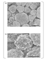
- FIG. 1A is an example of an electron microscope image of an electrode active material-containing layer that constitutes a positive electrode for a lithium ion secondary battery according to an embodiment of the present invention
- FIG. 1B is an enlarged image thereof. ..
- FIG. 3A is an electron microscope image of the electrode active material-containing layer in Comparative Example 1
- FIG. 3B is an electron microscope image of the electrode active material-containing layer in Example 1
- FIG. An electron microscope image of the electrode active material-containing layer in Example 2 and FIG. 3D are electron microscope images of the electrode active material-containing layer in Example 3.
- FIG. 3A is an electron microscope image of the electrode active material-containing layer in Comparative Example 1
- FIG. 3B is an electron microscope image of the electrode active material-containing layer in Example 1
- An electron microscope image of the electrode active material-containing layer in Example 2 and FIG. 3D are electron microscope images of the electrode active material-containing layer in Example 3.
- FIG. 3A is an electron microscope image of the electrode active material-containing layer in Comparative Example
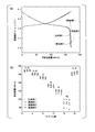
- FIG. 4 (a) is a graph showing an example of charge / discharge curves of the lithium ion secondary batteries in Examples 1 to 3 and Comparative Example 1
- FIG. 4 (b) is a charge / discharge test under conditions of different current densities.
- 3 is a graph showing the relationship between the number of cycles and the discharge capacity repeatedly performed.
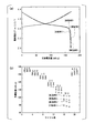
- FIG. 5 (a) is a graph showing an example of the charge / discharge curves of the lithium ion secondary batteries in Examples 4 to 6 and Comparative Example 1
- FIG. 5 (b) shows the relationship between the number of cycles and the discharge capacity. It is a graph.
- FIG. 6 is a graph showing the electric conductivity of the positive electrodes for lithium-ion secondary batteries in Examples 4 to 6 and Comparative Example 1.
- FIG. 7A is an example of the current-potential curve (cyclic voltammogram) of the positive electrode for a lithium ion secondary battery in Examples 4 to 6, and FIG. 7B shows the relationship between the scan rate and the current. It is a graph shown.
- FIG. 8 is a graph showing an example of cycle characteristics of positive electrodes for lithium ion secondary batteries in Examples 4 to 6 and Comparative Examples 1 and 2.
- FIG. 9A is an electron microscope image of the electrode active material-containing layer in Example 5 after the cycle test, and FIG. 9B is an enlarged image thereof.
- FIG. 10 is an electron microscope image of the electrode active material-containing layer in Comparative Example 1 after performing the cycle test.
- FIG. 11: is a figure which shows the XRD pattern in Example 5 and the comparative example 1 after performing a cycle test.
- the positive electrode for a lithium-ion secondary battery includes a current collector and an electrode active material-containing layer provided on the current collector.
- the current collector is made of, for example, a metal foil.
- the metal foil is suitable for use in various types of batteries such as a cylindrical type, a square type and a laminated type. Carbon may be vapor-deposited on the surface of the current collector in order to further improve the adhesion between the electrode active material and the current collector.
- the current collector on the positive electrode side for example, aluminum foil can be used.
- the current collector is preferably hydrophilized by surface treatment. Since the surface of the current collector is made hydrophilic, hydrogen bonds are easily formed when the electrode-forming slurry is dried, and an electrode having high adhesive strength can be obtained. Examples of the hydrophilic treatment on the surface of the current collector include a method of irradiating ultraviolet rays (UV) in an ozone (O 3 ) atmosphere (UV / O 3 treatment).
- UV ultraviolet rays
- O 3 ozone
- the electrode active material-containing layer contains active material particles and a conductive material that connects the active material particles to each other.
- the mass ratio (mass%) of active material particles: conductive material: other components in the electrode active material-containing layer is 95 to 99.7: 0.3 to 5: 0 to 1, preferably 98 to 99.7. : 0.3 to 2: 0 to 1, and more preferably 99 to 99.7: 0.3 to 1: 0 to 1. Since the mass ratio of the active material particles is as high as 95 to 99.7, the capacity per mass of the lithium ion secondary battery can be made extremely high.
- the active material particles are composed of a transition metal, which will be described later, and a composite oxide containing lithium.
- the behavioral particle size of the active material particles is preferably 0.1 ⁇ m or more and 30 ⁇ m or less, and more preferably 1 ⁇ m or more and 10 ⁇ m or less.
- the behavioral particle size of the active material is less than 0.1 ⁇ m, the number of particles of the active material per unit volume in the positive electrode increases, and the peel strength decreases, which is not preferable.
- the behavioral particle size of the active material exceeds 10 ⁇ m, it is difficult to increase the capacity of the battery. It is preferable to reduce impurities in advance by washing with water or the like to prevent the pH of the electrode forming slurry from increasing.
- the positive electrode active material particles for example, lithium cobalt oxide LiCoO 2 layered structure lithium nickel oxide LiNiO 2 having the same structure, the lithium manganese oxide LiMn 2 O 4 having a spinel structure, lithium iron phosphate LiFePO 4 having an olivine structure, or they Solid solution layered structure Li (Ni, Mn, Co) O 2 , layered structure Li (Ni, Al, Co) O 2, and spinel structure LiNi 0.5 Mn 1.5 O 4 .
- the active material particles in the present invention are not particularly limited as long as they can reversibly occlude and release Li, and known ones can also be used.
- the conductive material includes a first long carbon material having a first length and a second long carbon material having a second length that is larger than the first length.
- the 1st elongate carbon material connects the particle
- the second long carbon material is arranged so as to straddle a plurality of primary particles respectively constituting a plurality of secondary particles in the active material particles and connects the secondary particles to each other. ..
- the first long carbon material is, for example, a short first carbon nanotube
- the second long carbon material is, for example, a long second carbon nanotube.
- the short first carbon nanotubes show a gap between a plurality of primary particles constituting one secondary particle in the active material particle and a part of the surface of the plurality of primary particles.
- the particles are densely dispersed and arranged so as to cover, and self-aggregate in a bundle shape in a particle gap between a plurality of primary particles respectively constituting a plurality of adjacent secondary particles.
- the long second carbon nanotubes are sparsely distributed and arranged in a state of extending like filaments from the surface of the active material particles, and are self-aggregated densely in the particle gaps of a plurality of adjacent secondary particles.
- the first and second carbon nanotubes can also be referred to as a conduction aid.
- the ratio of the second length to the first length is 2 or more and 50 or less, preferably 7 or more and 34 or less, more preferably 7 or more and 20 or less, still more preferably 5 or more and 15 or less. If the ratio of the second length to the first length is less than 2, the electrical conductivity is not sufficiently improved, and if it exceeds 50, the dispersibility of the carbon nanotubes decreases. Therefore, the ratio of the second length to the first length is set to a value within the range.
- the first length of the first carbon nanotube is 0.2 ⁇ m or more and 1.0 ⁇ m or less, preferably 0.3 ⁇ m or more and 0.7 ⁇ m or less, and the diameter thereof is 0.01 ⁇ m or more and 0.04 ⁇ m or less.
- the second length of the second carbon nanotube is 2.0 ⁇ m or more and 10 ⁇ m or less, preferably 5 ⁇ m or more and 10 ⁇ m or less, more preferably 5 ⁇ m or more and 7 ⁇ m or less, and the diameter thereof is 0.001 ⁇ m or more and 0.005 ⁇ m. It is below.
- the first long carbon material is composed of first carbon nanotubes that are multi-wall carbon nanotubes (hereinafter, also referred to as MWCNT), and the second long carbon material is single-wall carbon nanotubes (hereinafter, also referred to as SWCNT).
- MWCNT multi-wall carbon nanotubes
- SWCNT single-wall carbon nanotubes
- the second carbon nanotubes are
- both the first carbon nanotubes and the second carbon nanotubes may be composed of multi-wall carbon nanotubes.
- the mass ratio (mass%) of the first carbon nanotube: the second carbon nanotube is 85 to 99: 1 to 15. More specifically, when the mass ratio of the active material particles in the electrode active material-containing layer is 95 mass% or more and less than 99.5 mass%, the mass ratio of the first carbon nanotubes to the second carbon nanotubes is 90. More preferably, the ratio is ⁇ 99: 1 to 10. When the mass ratio of the active material particles in the electrode active material-containing layer is 99.5 mass% or more and 99.7 mass% or less, the mass ratio of the first carbon nanotubes to the second carbon nanotubes is 85 to 90. Is more preferably 10 to 15.
- the temperature (TDTA) of the first exothermic peak in differential thermal analysis is 530 ° C or higher.
- combustion decomposition of carbon nanotubes occurs at the temperature at which the first exothermic peak is exhibited. Therefore, it is considered that the lower the first exothermic peak temperature of the differential thermal analysis is, the easier the carbon nanotubes are to be decomposed by combustion.
- the catalyst used for synthesizing carbon nanotubes remains, the TDTA tends to be low because the periphery of the metal particles is selectively oxidized and easily burned.
- carbon nanotubes, such as the cup-stack type in which many ends of the tube are exposed, also tend to have a low TDTA because oxidation and combustion proceed all at once.
- the first carbon nanotube, specific surface area as determined by BET method is less than 100 m 2 / g Ultra 750 meters 2 / g are preferred.
- the specific surface area is 100 m 2 / g or less, it is difficult to impart conductivity to a wide range, which is not preferable.
- the specific surface area is 750 m 2 / g or more, it is not preferable because it easily aggregates and it is difficult to maintain the dispersed state in the electrode forming slurry.
- a more preferred range is less than 105m 2 / g Ultra 600m 2 / g, furthermore preferably less than 110m 2 / g Ultra 500m 2 / g.
- specific surface area determined by the BET method is less than 100 m 2 / g Ultra 1000 m 2 / g.
- the specific surface area is 100 m 2 / g or less, it is difficult to impart conductivity to a wide range, which is not preferable.
- the specific surface area is 1000 m 2 / g or more, it is not preferable because it easily aggregates and it is difficult to maintain the dispersed state in the electrode forming slurry.
- a more preferred range is less than 105m 2 / g Ultra 800 m 2 / g, furthermore preferably less than 110m 2 / g Ultra 700m 2 / g.
- the first carbon nanotube preferably has a dibutyl phthalate (DBP) absorption amount D of 100 ml / 100 g or more and 600 ml / 100 g or less measured in accordance with JIS K6217-4.
- a conductive material having a DBP absorption amount D of less than 100 ml / 100 g is not preferable because it is difficult to impart conductivity to a wide range.
- the DBP absorption amount D exceeds 600 ml / 100 g, the aggregates are not easily loosened and it is difficult to disperse them, which is not preferable.
- a more preferable range is 125 ml / 100 g or more and 550 ml / 100 g or less, and a still more preferable range is 150 ml / 100 g or more and 500 ml / 100 g or less.
- the second carbon nanotube is not limited by the above DBP absorption amount.
- the first carbon nanotubes preferably have a large number of oxygen-containing groups (for example, hydroxyl groups) having hydrogen accepting properties.
- oxygen-containing groups for example, hydroxyl groups
- a hydrogen bond is easily formed and an electrode having high binding force can be obtained.
- the water vapor adsorption amount per unit area is more preferably 1.00 ⁇ 10 ⁇ 3 mg / m 2 or more, and further preferably 1.05 ⁇ 10 ⁇ 3 mg / m 2 or more.
- the amount of water vapor adsorbed per unit area can be adjusted by oxidizing the conductive material. If the amount of water vapor adsorbed is too high, the conductivity will be low, which is not preferable.
- the number of layers, length and diameter of the carbon nanotube can be confirmed and measured with a transmission electron microscope (TEM).
- TEM transmission electron microscope
- the conductive material is composed of a first carbon nanotube having the first length and a second carbon nanotube having the second length larger than the first length.
- the conductive material may contain a material other than the carbon nanotubes, provided that it contains the first carbon nanotubes and the second carbon nanotubes.
- materials other than carbon nanotubes include conductive materials such as carbon black, titanium nitride, ruthenium oxide, and polythiophene.
- the conductive material may not contain the first carbon nanotube and the second carbon nanotube. That is, the conductive material includes a first long carbon material having a first length and a second long carbon material having a second length larger than the first length, The one long carbon material and the second long carbon material may each be composed of one or more selected from carbon nanotubes, graphene, carbon nanofibers, carbon nanocones, and the like.
- the electrode active material-containing layer may contain other components in addition to the active material particles and the conductive material.
- the above-mentioned other components refer to those added for the purpose of preparing a slurry for electrode formation, and one or more materials other than the binder, for example, a thickener for adjusting the viscosity of the slurry for electrode formation, a conductive material. It is a polymeric material such as a dispersant for dispersing.
- the electrode active material-containing layer having the above structure does not contain an insulating binder such as PDVF or SBR, and contains a conductive material containing two carbon nanotubes having different lengths at a very high ratio, and thus has low electric resistance. Further, since the weight ratio of the active material particles in the electrode active material-containing layer is high, a lithium ion secondary battery having a high capacity per weight of the electrode active material-containing layer, that is, a lithium ion secondary battery having a high energy density can be obtained. .. Furthermore, since the electrode active material-containing layer has high adhesion to the current collector, a lithium ion secondary battery capable of withstanding a large current, that is, a lithium ion secondary battery having a high output density can be obtained.
- an insulating binder such as PDVF or SBR
- the method for manufacturing a positive electrode for a lithium-ion secondary battery includes a step of preparing a conductive material and a step of forming an electrode active material-containing layer.
- the first long carbon material having a first length and the second long carbon material having a second length larger than the first length are included, and the first long carbon material has a second length larger than the first length.
- a conductive material having a ratio of the second length of 2 or more and 50 or less is prepared.
- a long carbon material dispersion liquid in which the first long carbon material and the second long carbon material forming the conductive material are dispersed can be prepared.
- the long carbon material dispersion liquid includes, for example, a first carbon nanotube that is a multi-wall carbon nanotube, a second carbon nanotube that is a single-wall carbon nanotube, a dispersant, and a dispersion medium.
- the long carbon material dispersion may not contain the first carbon nanotubes and the second carbon nanotubes. That is, the long carbon material dispersion liquid includes a first long carbon material having a first length and a second long carbon material having a second length larger than the first length. Including a dispersant and a dispersion medium, wherein the first long carbon material and the second long carbon material are each selected from carbon nanotubes, graphene, carbon nanofibers, carbon nanocones, etc. 1 or It may be composed of a plurality.
- the dispersion liquid containing the above two kinds of carbon nanotubes preferably has a carbon nanotube content of 5% by mass or more.
- a low-concentration dispersion liquid of less than 5% by mass is not preferable because the amount of the dispersion medium increases with the desired amount of carbon nanotubes when the electrode slurry is prepared, the solid content concentration decreases, and it becomes difficult to apply.
- the content of carbon nanotubes is more preferably 6% by mass or more and 27% by mass or less, and more preferably 7% by mass or more and 25% by mass or less.
- a polar aprotic solvent is preferred as the dispersion medium used in the carbon nanotube dispersion.
- the aprotic polar solvent By using the aprotic polar solvent, it becomes easy to balance the dispersion of the first carbon nanotubes and the second carbon nanotubes in the solvent, adsorption on the surface of the electrode active material, and formation of a bundle structure by aggregation of carbon nanotubes. As a result, the carbon nanotubes are uniformly distributed between the active material particles and at the interface between the active material particles and the current collector, so that it is possible to obtain an electrode having a high binding force.
- the most preferred aprotic polar dispersion medium is N-methylpyrrolidone, but other examples include dimethylacetamide, dimethylformamide, dimethylsulfoxide, acetonitrile and the like.
- the dispersant used for the carbon nanotube dispersion liquid preferably has many oxygen-containing groups (for example, hydroxyl groups) having hydrogen accepting properties. Specific examples thereof include carboxymethyl cellulose (CMC), polyvinyl alcohol (PVA), polyvinyl pyrrolidone (PVP), polyvinyl acetal (PBAc), and the like.
- the content of the dispersant is preferably 30% by mass or less, and more preferably 25% by mass or less, based on the carbon nanotubes. When the dispersant exceeds 30% by mass with respect to the carbon nanotubes, the contents of the active material and the conductive material in the formed electrode are reduced, which is not preferable.
- the carbon nanotube dispersion liquid preferably has a dynamic light scattering particle diameter (median diameter: D 50 ) of 400 nm or less as a behavioral particle diameter of the carbon nanotubes in the dispersion liquid.
- a dispersion liquid having a dynamic light scattering particle diameter (D 50 ) of more than 400 nm is poorly dispersed, and carbon nanotubes easily form aggregates and settle, resulting in poor dispersion stability. Even if the dynamic light-scattering particle diameter (D 50 ) is temporarily reduced by the dispersion treatment, the carbon nanotubes re-aggregate into pills in the dispersion liquid to some extent, so the lower limit is about 100 nm.
- the dynamic light scattering particle size (D 50 ) as the behavioral particle size of the carbon nanotubes in the dispersion is more preferably 120 nm or more and 390 nm or less, still more preferably 150 nm or more and 380 nm or less.
- the dispersion liquid containing the above two kinds of carbon nanotubes has a viscosity of 5 mPa ⁇ s or more and 300 MPa ⁇ s or less at a shear rate of 383 s ⁇ 1 , depending on the kind and amount of the dispersant and the carbon nanotube content. Is preferred.
- the dispersion liquid in the present invention refers to a liquid in which the marks scooped from the container return to a smooth surface with time. When the viscosity is less than 5 mPa ⁇ s, the carbon nanotubes may not be sufficiently dispersed, which is not preferable.
- the viscosity of the carbon nanotube dispersion is more preferably 5 mPa ⁇ s or more and 250 MPa ⁇ s or less, further preferably 5 mPa ⁇ s or more and 200 MPa ⁇ s or less, and particularly preferably 10 mPa ⁇ s or more and 120 MPa ⁇ s or less.
- the carbon nanotube dispersion liquid can be appropriately selected and manufactured as long as it is a method of dispersing the carbon nanotubes, the dispersant, and, if necessary, the dispersant in the dispersion medium. Specifically, a bead mill, jet mill, ultrasonic disperser or the like may be used.
- the electrode forming material containing the conductive material and the active material particles is applied to the current collector to form an electrode active material containing layer.
- the electrode active material-containing layer is formed using an electrode forming material that does not contain a binder.
- the conductive material, the active material particles, and the electrode forming dispersion medium are added and mixed to prepare an electrode forming slurry.
- the above carbon nanotube dispersion liquid may be used when the electrode forming material is produced.
- a screw type kneader, a ribbon mixer, a universal mixer, a planetary mixer and the like can be mentioned.
- the method for applying the electrode forming slurry to the current collector is not particularly limited, and examples thereof include a metal mask printing method, an electrostatic coating method, a dip coating method, a spray coating method, a roll coating method, a doctor blade method, and a gravure coating.
- Known methods such as a method, a screen printing method, and a die coater method can be mentioned.
- An electrode of a lithium ion secondary battery can be manufactured through each process.
- the lithium ion secondary battery according to this embodiment includes the positive electrode for the lithium ion secondary battery, the negative electrode, and the electrolyte.
- the lithium ion secondary battery can be obtained, for example, by arranging the positive electrode and the negative electrode for the lithium ion secondary battery so as to face each other with the separator interposed therebetween and injecting an electrolytic solution.
- As the current collector on the negative electrode side for example, aluminum foil can be used.
- the structure of the lithium-ion secondary battery is not particularly limited, but the positive electrode and the negative electrode molded in a strip shape, a spirally wound electrode group wound via a separator, inserted into a battery case, and sealed.
- the structure is such that a laminated positive electrode group in which a positive electrode and a negative electrode molded in a flat plate shape are sequentially laminated via a separator is enclosed in an exterior body.
- the lithium ion secondary battery is used as, for example, a paper battery, a button battery, a coin battery, a laminated battery, a cylindrical battery, a prismatic battery, or the like.
- a non-woven fabric containing a polyolefin such as polyethylene or polypropylene as a main component, a cloth, a microporous film, or a combination thereof can be used. If the lithium ion secondary battery to be produced has a structure in which the positive electrode and the negative electrode do not come into direct contact with each other, it is not necessary to use a separator.
- the organic electrolyte used in the lithium-ion secondary battery known organic electrolytes, inorganic solid electrolytes, and polymer solid electrolytes can be used. From the viewpoint of electrical conductivity, the organic electrolytic solution is preferable.
- the organic electrolyte is generally an aprotic solvent having a high dielectric constant such as ethylene carbonate, propylene carbonate, butylene carbonate, ⁇ -butyrolactone, dimethyl carbonate, ethyl methyl carbonate, diethyl carbonate, methyl propyl carbonate, dipropyl carbonate, diethyl ether.
- Acetate or propionate such as tetrahydrofuran, 1,2-dimethoxyethane, 1,2-diethoxyethane, 1,3-dioxolane, sulfolane, methylsulfolane, acetonitrile, propionitrile, anisole, methyl acetate, etc.
- aprotic low viscosity solvent It is desirable to use these aprotic high dielectric constant solvents and aprotic low viscosity solvents together in an appropriate mixing ratio.
- ionic liquids with imidazolium, ammonium, and pyridinium type cations can be used.
- the counter anion is not particularly limited, but ionic liquids such as BF 4 ⁇ , PF 6 ⁇ , (CF 3 SO 2 ) 2 N ⁇ and the like are used by mixing with the above-mentioned non-aqueous electrolyte solvent. be able to.
- solutes of these solvents include lithium salts such as LiPF 6 , (CF 3 SO 2 ) 2 NLi, LiBF 4 , LiClO 4 , LiAsF 6 , CF 3 SO 3 Li, C 4 F 9 SO 3 Li, CF 3 CO 2 Li, (CF 3 CO 2) 2 NLi, C 6 F 5 SO 3 Li, C 8 F1 7 SO 3 Li, (C 2 F 5 SO 2) 2 NLi, (C 4 F 9 SO 2) (CF 3 SO 2 ) NLi, (FSO 2 C 6 F 4 ) (CF 3 SO 2 ) NLi, ((CF 3 ) 2 CHOSO 2 ) 2 NLi, (CF 3 SO 2 ) 3 CLi, (3,5- (CF) 3 ) 2 C 6 F 3 ) 4 BLi, LiCF 3 , LiAlCl 4 , C 4 BO 8 Li and the like can be mentioned, and any one of these can be used alone or in combination.
- lithium salts such as LiPF 6 , (CF 3 SO
- polymer solid electrolyte examples include a polyethylene oxide derivative and a polymer containing the derivative, a polypropylene oxide derivative and a polymer containing the derivative, a phosphate ester polymer, a polycarbonate derivative and a polymer containing the derivative. It should be noted that the selection of members other than those described above that are necessary for the battery configuration is not restricted in any way.
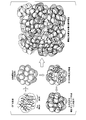
- FIG. 2 is a schematic diagram illustrating details of the connection structure in the electrode active material-containing layer of FIG. 1.
- the first long carbon material is composed of short first carbon nanotubes that are multi-wall carbon nanotubes
- the second long carbon material is long second carbon nanotubes that are single-wall carbon nanotubes. The description will be made by taking the case of
- the short first carbon nanotubes are dispersed. It enters between a plurality of primary particles and binds to each of the adjacent primary particles. That is, the first carbon nanotubes connect the plurality of primary particles of the electrode active material. Moreover, the long second carbon nanotubes are dispersed and bound to the plurality of secondary particles. As a result, the second carbon nanotubes are arranged so as to straddle the plurality of primary particles respectively constituting the plurality of secondary particles, and connect the secondary particles to each other.
- the active material precursor since the active material precursor is generally synthesized by the coprecipitation method, it takes a form of secondary particles in which primary particles are aggregated. A lithium salt is solid-dissolved in the active material precursor having such a form to synthesize active material particles. At this time, the active material particles usually maintain the original secondary particle form.
- the active material in the form of secondary particles is prepared into a paste in which two types of carbon nanotubes having different lengths are mixed, and the paste is applied to the electrodes so that the carbon nanotubes self-aggregate to incorporate the active material particles. , To form a complex.
- the short first carbon nanotubes are selectively adsorbed in the gaps between the primary particles exposed on the surface of the active material particles in the form of secondary particles.
- the extra first carbon nanotubes are supplied to the gaps between adjacent active material particles in the form of secondary particles and self-aggregate into a bundle to form a network.
- the long second carbon nanotubes are dispersed so as to straddle the primary particles exposed on the surface of the active material particles in the form of secondary particles, and are adsorbed to the active material particles. ..
- the second carbon nanotubes that cannot be adsorbed on the surface are supplied to the gaps between the adjacent secondary particles, and self-aggregate into a bundle with the short first carbon nanotubes to form a network.
- the primary particles are connected by the short first carbon nanotubes and the long second carbon nanotubes are connected.
- the secondary particles are connected to each other, thereby forming a three-dimensional network network of the first and second carbon nanotubes.
- the content of the active material particles is 99.7 mass% without using an insulating binder such as PVDF or SBR in the electrode active material-containing layer.
- the short first carbon nanotubes of the conductive material mainly connect the adjacent active material particles to each other, an electron conduction path is formed between the adjacent active material particles and the three-dimensional structure is formed on the current collector. A reticulated network structure is formed. Due to the action of the first carbon nanotubes, the active material particles are retained on the current collector without falling off from the electrode active material-containing layer.
- One of the causes of deterioration in long-term use of the lithium ion secondary battery is that the active material particles are physically separated from the conductive path in the electrode. Above all, when the electrode active material-containing layer is peeled off from the current collector, a large amount of active material particles are separated from the conductive path, which is fatal.
- the electrode active material-containing layer usually contains a binder that binds the active material particles.
- the short first carbon nanotubes play a role of forming the reticulated network structure, it is possible to prevent the active material particles from being desorbed from the conductive path in the electrode. It is possible to develop high adhesion between the active material particles and sufficient adhesion of the active material particles to the current collector without including a binder in the containing layer.
- the long second carbon nanotubes of the conductive material connect not only the adjacent active material particles but also other active material particles located around them, the carbon nanotubes contained in the conductive material are As compared with the case where only one carbon nanotube is used, a low resistance and continuous electron conduction path is formed among a larger number of active material particles. Due to the action of the second carbon nanotube, the electrical conductivity is significantly improved.
- the short first carbon nanotubes play a role of forming a reticulated network structure, so that the active material particles are mechanically connected to each other, and sufficient adhesion of the active material particles to the current collector is exhibited. be able to.
- the long second carbon nanotubes play a role of forming a continuous electron conduction path with low resistance, so that the active material particles are not separated from each other as compared with the case where only the short first carbon nanotubes are formed. Are electrically connected, and the electrical conductivity of the electrode active material-containing layer is dramatically improved.
- the active material particles by binding the active material particles to each other by the short first carbon nanotubes, it is not necessary to include a binder in the electrode active material-containing layer, so that the active material particles are extremely high in the electrode active material-containing layer. It can be contained in a ratio.
- a carbon material with high crystallinity is explained as an assembly of graphene sheets made of only carbon, but the ends and defects of this graphene sheet are usually terminated with hydrogen, but the activity is high and the surrounding environment is high. Is easily replaced by a functional group.
- a functional group For example, when carbon nanotubes having a graphene sheet formed in a tubular shape are dispersed in water, if the carbon nanotubes are cut and shortened, the ends are modified with hydroxyl groups derived from water due to the activity of the cut surface. Therefore, a carbon nanotube having a constriction has more active surfaces generated in water, and thus is more likely to have a hydrophilic group.
- the hydrophilic groups on the fibrous carbon nanotubes form hydrogen bonds with the hydrophilic groups on other carbon nanotubes and the hydrophilic groups on the surface of the current collector, thereby fixing multiple carbon nanotubes to the current collector.
- the active material particles can be retained without falling off from the electrode active material-containing layer.
- Multi-walled carbon nanotubes (1st CNT, manufactured by Toda Kogyo, product name “TCW-261”) and single-walled carbon nanotubes (2nd CNT, manufactured by Meijo Nano Carbon Co., product name “eDIPSEC1.5n”)
- a conductive material was prepared by mixing the carbon nanotubes such that the mass ratio thereof was the value shown in Table 1.
- the first CNTs had a length of 0.3 ⁇ m or more and 0.7 ⁇ m, and an average length of The second CNTs had a length of 5 ⁇ m or more and 10 ⁇ m or less and an average length of 7 ⁇ m, the obtained conductive material, the electrode forming dispersion medium, and the active material particles NCM523 (nickel).
- Cobalt manganese lithium was mixed to prepare an electrode forming material, the electrode forming material was applied to an aluminum foil and dried to prepare a positive electrode for a lithium ion secondary battery.
- Example 1 A positive electrode for a lithium ion secondary battery was produced in the same manner as in Example 1 except that only the multi-walled carbon nanotubes were used as the conductive material and only the multi-walled carbon nanotubes (MWCNTs) forming the first CNTs were used.
- MWCNTs multi-walled carbon nanotubes
- Multi-walled carbon nanotubes and single-walled carbon nanotubes were mixed so that the mass ratio of multi-walled carbon nanotubes: single-walled carbon nanotubes was the value shown in Table 1 to prepare a conductive material.
- the obtained conductive material, the dispersion medium for electrode formation, and NCM523 (nickel-cobalt-manganese-lithium), which are active material particles, are mixed to prepare an electrode formation material, and the electrode formation material is an aluminum foil.
- NCM523 nickel-cobalt-manganese-lithium
- Example 2 A positive electrode for a lithium ion secondary battery was produced in the same manner as in Example 4 except that only the multi-walled carbon nanotubes were used as the conductive material and only the multi-walled CNTs constituting the first CNTs were used.
- Example 7 A positive electrode for a lithium ion secondary battery was produced in the same manner as in Examples 1 to 3 except that the active material particles were replaced with NCA (layered structure LiNi 0.82 Al 0.03 Co 0.15 O 2 ).
- Comparative example 3 A positive electrode for a lithium ion secondary battery was produced in the same manner as in Comparative Examples 1 and 2 except that the active material particles were replaced with NCA (layered structure LiNi 0.82 Al 0.03 Co 0.15 O 2 ).
- the positive electrodes for lithium ion secondary batteries of Examples 1 to 9 and Comparative Examples 1 to 3 were measured and evaluated by the following methods.
- Examples 1 to 3 and Comparative Example 1 a small piece of the electrode sample was fixed on a sample table and observed at 10 kV using an SEM (JSM7600F manufactured by JEOL Ltd.). The presence or absence of PDVF or SBR can be determined by analyzing the electrode cross section. (The TRC News No. 117 (2013)). Electron microscope images of the obtained electrode active material-containing layer are shown in FIGS. 3 (a) to 3 (d). Examples 1 to 3 correspond to FIGS. 3B to 3D, respectively, and Comparative Example 1 corresponds to FIG. 3A. From this observation result, as the content of single-walled CNTs increased, many fibrous single-walled CNTs were present on the surface of the active material particles, and more active material particles were connected by the single-walled CNTs. Can be confirmed.
- the prepared half cell was set in a charging / discharging device (Battery charging / discharging device "HJ1020Msd8" manufactured by Hokuto Denko KK), and Li was inserted into and desorbed from the positive electrode within a voltage range of 2.8V to 4.3V.
- the charging / discharging was carried out by constant current charging (CC charging) and constant current discharging (CC discharging) at 1C. Then, this charging and discharging was repeated 200 times, and the discharge capacity at that time was measured. The results are shown in Fig. 8.
- Example 2 From the results of FIGS. 4 (a) and 4 (b), in any of Examples 1 to 3 in which the active material particles (NCM523) were contained at 99% by weight, a long single piece was formed as a part of the conductive material. It was found that since the layer CNT was contained, the discharge capacity was increased as compared with Comparative Example 1. Further, comparing Examples 1 to 3, it was found that the discharge capacity reached the maximum value when the content of the single-walled CNT contained in the positive electrode was 0.05% by weight (Example 2).
- the content of the single-walled CNT is 0.1% by weight (Example 3)
- the content of the multi-layered CNT is reduced to 0.9% by weight, and the three-dimensional reticulated network structure due to the multi-layered CNT is formed. Is not sufficiently formed, and it is speculated that the discharge capacity decreased due to the decrease in the active material particle utilization rate.
- Example 5 Although the electric conductivity was low, when the content of the single-wall CNT was 0.06% by weight (Example 5), the electric conductivity almost equal to that of Comparative Example 1 was obtained. Moreover, in Example 5, although the content of the first CNTs is lower than that of Comparative Example 1 and the content of the second CNTs is higher than that of Example 1, the electrical conductivity is lower than that of Comparative Example 1.
- Example 6 although the content of the first CNTs was smaller than that of Example 5 and the content of the second CNTs was larger than that of Example 5, the electrical conductivity was lower than that of Comparative Example 1. From these results, the average electron conductivity inside the electrode is higher than the electron conductivity of each CNT having different first and second lengths, that is, the CNT network formed by the composite of each CNT and the active material particles. It is presumed that the connection structure of is dominant.
- the mass ratio of the first CNT and the second CNT greatly affects the electric conductivity, and even if the mass ratio of the conductive material (CNT) to the electrode active material-containing layer is the same, the coexistence ratio of the first CNT and the second CNT ( It was found that the electrical conductivity greatly differs depending on the mass ratio). Furthermore, in order to stably form a CNT network uniformly inside the electrode, the short first CNTs play an important role, and the coexistence of the long single-walled CNTs causes more active material particles to be dispersed between them. It is presumed that the self-assembly of the first CNT was induced to form a low resistance and continuous electron conduction path.
- FIG. 9A is an electron microscope image of the electrode active material-containing layer in Example 5 after the cycle test
- FIG. 9B is an enlarged image thereof.
- the mass ratio of the short first CNTs to the long second CNTs is 88:12.
- the primary particles of the electrode active material were connected by the short first CNTs (multilayer) to form the secondary particles, and It can be seen that the secondary particles are connected by the elongated second CNT (single layer). Therefore, in the configuration of Example 5, it can be confirmed that the short first CNTs and the long CNTs form a three-dimensional network network structure, whereby the active material particles are firmly bonded to each other.
- FIG. 10 is an electron microscope image of the electrode active material-containing layer in Comparative Example 1 after the cycle test.
- Comparative Example 1 only the short first CNTs were used, and the long second CNTs (single layer) were not used.
- FIG. 10 in Comparative Example 1, a plurality of large voids are generated between the particles of the electrode active material. Therefore, in Comparative Example 1, it can be seen that the layered structure of the electrode active material collapses due to expansion and contraction due to repeated charge and discharge.
- FIG. 11 is a figure which shows the XRD pattern in Example 5 and the comparative example 1 after performing a cycle test.
- I (003) shows the peak intensity corresponding to the layered rock salt structure of the electrode active material
- I (104) shows the peak intensity corresponding to the rock salt structure of the electrode active material.
- the XRD pattern was measured by an X-ray diffractometer (manufactured by Rigaku Corporation, device name "MiniFlex-II").
- the peak intensity ratio I (003) / I (104) of Example 5 is 1.19, whereas the peak intensity ratio of Comparative Example 1 is 0.86.
- the peak intensity ratio of No. 5 is larger than that of Comparative Example 1.
- the electrode active material-containing layer contains the short first CNTs and the long second CNTs at a predetermined ratio, whereby the atomic arrangement of transition metals such as Li and Ni in the electrode active material. It was found that the layered rock-salt type structure in which each layer was superposed was maintained, and the decrease in discharge capacity during repeated charging and discharging could be suppressed.
Landscapes
- Chemical & Material Sciences (AREA)
- Engineering & Computer Science (AREA)
- Materials Engineering (AREA)
- Chemical Kinetics & Catalysis (AREA)
- Electrochemistry (AREA)
- General Chemical & Material Sciences (AREA)
- Nanotechnology (AREA)
- Organic Chemistry (AREA)
- Manufacturing & Machinery (AREA)
- Inorganic Chemistry (AREA)
- Battery Electrode And Active Subsutance (AREA)
- Carbon And Carbon Compounds (AREA)
Abstract
Description
本願は、2018年11月22日に、日本に出願された特願2018-219707号に基づき優先権を主張し、その内容をここに援用する。
[1]集電体と、前記集電体上に設けられた電極活物質含有層とを備え、
前記電極活物質含有層は、活物質粒子と、活物質粒子同士を接続する導電材とを含み、
前記電極活物質含有層における活物質粒子:導電材:その他の成分の質量比が、95~99.7:0.3~5:0~1であり、
前記導電材は、第1の長さを有する第1長尺状炭素材料と、前記第1の長さよりも大きい第2の長さを有する第2長尺状炭素材料とを含み、
前記第1の長さに対する前記第2の長さの比が、2以上50以下である、リチウムイオン二次電池用正極。
前記第2長尺状炭素材料が、単層カーボンナノチューブである第2カーボンナノチューブで構成され、
前記第1カーボンナノチューブ:前記第2カーボンナノチューブの質量比が、85~99:1~15である、上記[1]に記載のリチウムイオン二次電池用正極。
前記第2長尺状炭素材料が、前記活物質粒子において複数の二次粒子をそれぞれ構成する複数の一次粒子間を跨ぐように配置されて前記二次粒子同士を連結している、上記[1]に記載のリチウムイオン二次電池用正極。
前記導電材と活物質粒子とを含む電極形成用材料を集電体に塗布して、電極活物質含有層を形成する工程と、
を有する、リチウムイオン二次電池用正極の製造方法。
前記第2長尺状炭素材料が、単層カーボンナノチューブである第2カーボンナノチューブで構成され、
前記第1カーボンナノチューブ:前記第2カーボンナノチューブの質量比が、85~99:1~15である、上記[5]に記載のリチウムイオン二次電池用正
本実施形態に係るリチウムイオン二次電池用正極は、集電体と、上記集電体上に設けられた電極活物質含有層とを備えている。
集電体は、例えば金属箔で構成される。金属箔は、円筒型、角型、ラミネート型といった多様な形の電池で使用するのに適している。電極活物質と集電体の密着性を更に高めるために、集電体の表面にカーボンが蒸着されていてもよい。
電極活物質含有層は、図1(a)および図1(b)に示すように、活物質粒子と、該活物質粒子同士を接続する導電材とを含んでいる。
電極活物質含有層における活物質粒子:導電材:その他の成分の質量比(質量%)は、95~99.7:0.3~5:0~1であり、好ましくは98~99.7:0.3~2:0~1であり、より好ましくは99~99.7:0.3~1:0~1である。活物質粒子の質量比が95~99.7と非常に高いため、リチウムイオン二次電池の質量当たりの容量を極めて高くすることが可能となる。
活物質粒子は、後述の遷移金属とリチウムを含む複合酸化物などで構成される。活物質粒子の挙動粒子径は、0.1μm以上30μm以下が好ましく、1μm以上10μm以下が更に好ましい。活物質の挙動粒子径が0.1μm未満の場合、正極内における単位体積あたりの活物質の粒子数が多くなり、剥離強度が低下するため好ましくない。活物質の挙動粒子径が10μmを超える場合、電池の高容量化が困難となる。水洗等で不純物を予め低減させ、電極形成用スラリーのpHが高くならないようにすることが好ましい。
導電材は、第1の長さを有する第1長尺状炭素材料と、上記第1の長さよりも大きい第2の長さを有する第2長尺状炭素材料とを含む。第1長尺状炭素材料は、活物質粒子における一の二次粒子を構成する複数の一次粒子の粒子同士を連結すると共に、隣接する二次粒子をそれぞれ構成する複数の一次粒子の粒子同士を連結しているのが好ましい。また、第2長尺状炭素材料は、上記活物質粒子において複数の二次粒子をそれぞれ構成する複数の一次粒子間を跨ぐように配置されて当該二次粒子同士を連結しているのが好ましい。
上記第1の長さに対する上記第2の長さの比が、2未満であると、電気伝導性向上が十分でなく、50を超えると、カーボンナノチューブの分散性が低下する。よって、上記第1の長さに対する上記第2の長さの比を、上記範囲内の値とする。
上記第1カーボンナノチューブの第1の長さは、0.2μm以上1.0μm以下、好ましくは0.3μm以上0.7μm以下であり、その直径は、0.01μm以上0.04μm以下である。また、上記第2カーボンナノチューブの第2の長さは、2.0μm以上10μm以下、好ましくは5μm以上10μm以下、より好ましくは5μm以上7μm以下であり、その直径は、0.001μm以上0.005μm以下である。
但し、導電材は、上記第1カーボンナノチューブおよび第2カーボンナノチューブを含有することを前提として、カーボンナノチューブ以外の材料を含有してもよい。カーボンナノチューブ以外の材料としては、例えば、カーボンブラック、窒化チタン、酸化ルテニウム,ポリチオフェン等の導電材料が挙げられる。
本実施形態に係るリチウムイオン二次電池用正極の製造方法は、導電材を準備する工程と、電極活物質含有層を形成する工程とを有する。
本実施形態では、バインダーを含まない電極形成用材料を用いて、電極活物質含有層を形成する。このとき、上記導電材と、活物質粒子と、電極形成用分散媒を添加して混合することによって、電極形成用スラリーを作製することができる。また、電極形成用材料を作製する際に、上記のカーボンナノチューブ分散液を用いてもよい。混合のための装置としては、スクリュー型ニーダー、リボンミキサー、万能ミキサー、プラネタリーミキサー等が挙げられる。
本実施形態に係るリチウムイオン二次電池は、上記リチウムイオン二次電池用正極と、負極と、電解質とを備える。
リチウムイオン二次電池は、例えば、上記リチウムイオン二次電池用正極と負極とをセパレータを介して対向するように配置し、電解液を注入することにより得ることができる。負極側の集電体としては、例えばアルミニウム箔を用いることができる。
また、長尺の第2カーボンナノチューブが分散して、複数の二次粒子と結着すする。これにより、第2カーボンナノチューブが、複数の二次粒子をそれぞれ構成する複数の一次粒子間を跨ぐように配置されて当該二次粒子同士を連結する。
リチウムイオン二次電池の長期使用における劣化要因の一つに、活物質粒子が電極内導電経路から物理的に外れてしまうことが挙げられる。中でも、集電体から電極活物質含有層が剥離すると、大量の活物質粒子が導電経路から離れてしまうので致命的である。よって、通常、電極活物質含有層には活物質粒子を結着するバインダーが含有される。
一方、本発明では、短尺の第1カーボンナノチューブが上記網状ネットワーク構造を形成する役割を担うことで、活物質粒子が電極内導電経路から脱離するのを抑制することができるので、電極活物質含有層にバインダーを含有させること無く、活物質粒子同士の高い密着性や、集電体に対する活物質粒子の十分な密着性を発現させることができる。
多層カーボンナノチューブ(第1CNT、戸田工業社製、製品名「TCW-261」)および単層カーボンナノチューブ(第2CNT、名城ナノカーボン社製、製品名「eDIPSEC1.5n)を、多層カーボンナノチューブ:単層カーボンナノチューブの質量比が表1の値となるように混合して、導電材を作製した。混合前の状態で、第1CNTは、その長さが0.3μm以上0.7μm、平均長さが0.5μmであり、第2CNTは、その長さが5μm以上10μm以下、平均長さが7μmであった。得られた導電材と、電極形成用分散媒と、活物質粒子であるNCM523(ニッケルコバルトマンガンリチウム)とを混合して電極形成用材料を作製し、この電極形成用材料をアルミニウム箔に塗布して、これを乾燥させてリチウムイオン二次電池用正極を作製した。
導電材を多層カーボンナノチューブのみとし、且つ、第1CNTを構成する多層カーボンナノチューブ(MWCNT)のみを用いたこと以外は、実施例1と同様にして、リチウムイオン二次電池用正極を作製した。
多層カーボンナノチューブおよび単層カーボンナノチューブ(SWCNT)を、多層カーボンナノチューブ:単層カーボンナノチューブの質量比が表1の値となるように混合して、導電材を作製した。得られた導電材と、電極形成用分散媒と、活物質粒子であるNCM523(ニッケル-コバルト-マンガン-リチウム)とを混合して電極形成用材料を作製し、この電極形成用材料をアルミニウム箔に塗布して、リチウムイオン二次電池用正極を作製した。
導電材を多層カーボンナノチューブのみとし、且つ、第1CNTを構成する多層CNTのみを用いたこと以外は、実施例4と同様にして、リチウムイオン二次電池用正極を作製した。
活物質粒子をNCA(層状構造LiNi0.82Al0.03Co0.15O2)に代えたこと以外は、実施例1~3と同様にしてリチウムイオン二次電池用正極を作製した。
活物質粒子をNCA(層状構造LiNi0.82Al0.03Co0.15O2)に代えたこと以外は、比較例1~2と同様にしてリチウムイオン二次電池用正極を作製した。

実施例1~3および比較例1について、電極サンプルの小片を試料台に固定し、SEM(日本電子社製、JSM7600F)を用いて10kVで観察した。PDVFあるいはSBRの有無は電極断面を分析することによって判断することができる。(The TRC News No.117(2013))。得られた電極活物質含有層の電子顕微鏡画像を、図3(a)~図3(d)に示す。実施例1~3が、図3(b)~図3(d)にそれぞれ対応しており、比較例1が、図3(a)に対応している。
この観察結果から、単層CNTの含有量の増大に伴って、繊維状の単層CNTが活物質粒子の表面に数多く存在し、単層CNTによってより多くの活物質粒子が連結されていることが確認できる。
孤立分散した第1CNTおよび第2CNTを透過型電子顕微鏡(TEM)を用いて観察して、(第2CNTの長さ)/(第1CNTの長さ)の比を求めた。結果を表1に示す。
電気化学測定は、対極LiのR2032型ハーフセルに対し、恒温器(エスペック社製、SU-221)を用いて室温環境下で行った。
まず、露点-80℃以下の乾燥アルゴン雰囲気下で、コインセル用キャップとケースの間に、14mmφの電極と14mmφの金属リチウム箔とをセパレータ(セルガード#2500)を介して積層させた。次に、この積層体に、電解液(EC(エチレンカーボネート)とDMC(ジメチルカーボネート)を3:7の割合で混合したものを溶媒とし、これに電解質としてLiPF6を1mol/Lの濃度で溶解したもの)を適量加えて、宝泉社製手動コインセルカシメ機を用いてかしめることにより、ハーフセルとした。
作製したハーフセルをポテンショ・ガルバノスタット(北斗電工社製、電池充放電装置「HJ1020Msd8」)にセットし、2.8Vから4.3Vの範囲において正極へのLi挿入脱離を行った。充電は0.2Cで定電流充電(CC充電)を行い、放電は0.2C、0.5C、1C、3C、5C、10C、0.2Cの順に3回毎に放電レートを変えた定電流放電(CC放電)を行った。結果を図4(a)~図4(b)および図5(a)~図5(b)に示す。
四短針測定器(共和理研社製、K-705RS)を用いて、実施例4~6及び比較例1における正極の電気伝導度を求めた。結果を図6に示す。
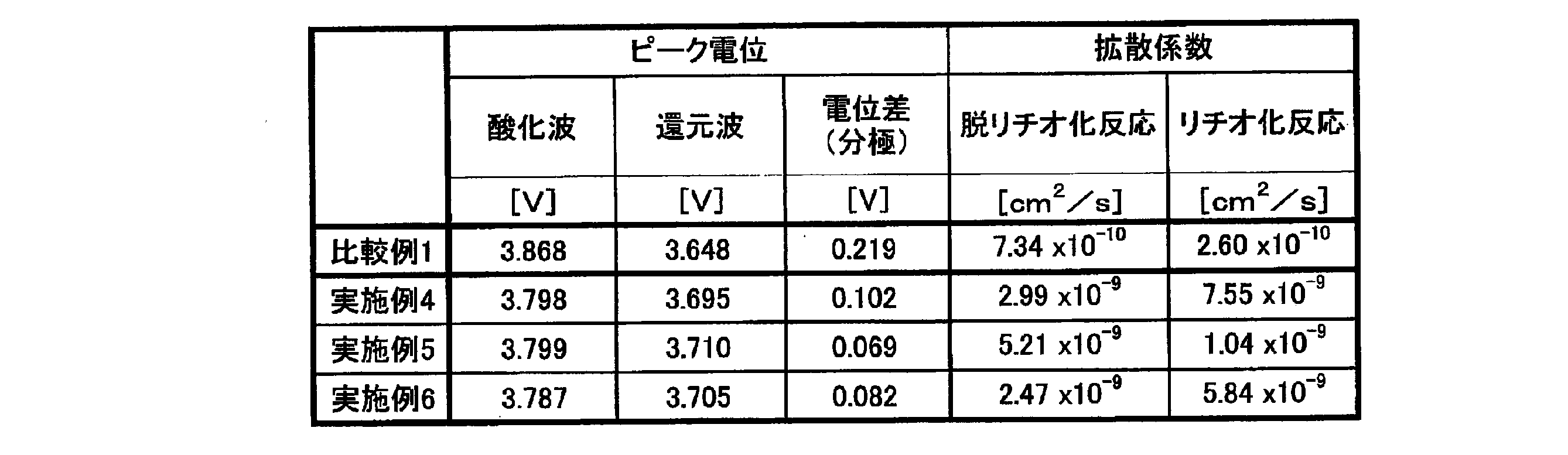
ポテンショ・ガルバノスタット(北斗電工社製、電池充放電装置「HJ1020Msd8」)を用いて電位の掃引を行い、サイクリックボルタモグラムから、ピーク電位を求めた。掃引速度は、0.1mV/とした。結果を図7(a)および表2に示す。また、掃引速度を変化させて、コレットル式を用いてピーク電流Ipを求め、横軸に掃引速度vの1/2乗、縦軸にピーク電流Ipを取り、直線の傾きからリチウムイオンの拡散係数を算出した。結果を図7(b)に示す。
作製したハーフセルを充放電装置(北斗電工社製、電池充放電装置「HJ1020Msd8」)にセットし、電圧2.8V~4.3Vの範囲で正極へのLi挿入脱離を行った。
充放電は1Cで定電流充電(CC充電)および定電流放電(CC放電)を行った。そして、この充放電を200回繰り返し、その際の放電容量を測定した。結果を図8に示す。
また、実施例1~3を比較すると、正極に含まれる単層CNTの含有量が0.05重量%(実施例2)であるときに、放電容量が最大値となることが分かった。
単層CNTの含有量が0.1重量%である場合には(実施例3)、多層CNTの含有量が0.9重量%に低下し、多層CNTに因る三次元的な網状ネットワーク構造が十分に形成されず、活物質粒子利用率の低下により放電容量が低下したと推察される。
実施例4~6を比較すると、正極に含まれる単層CNTの含有量が0.06重量%(実施例5)であるときに、放電容量が最大値となることが分かった。単層CNTの含有量が0.075重量%である場合には(実施例67)、多層CNTの含有量が0.425重量%に低下し、多層CNTに因る三次元的な網状ネットワーク構造が十分に形成されず、活物質粒子利用率の低下により放電容量が低下したと推察される。
また、実施例5では、第1CNTの含有量は比較例1よりも少なく、第2CNTの含有量は実施例1よりも多いにもかかわらず、電気伝導度は比較例1よりも低い。更に、実施例6では、第1CNTの含有量は実施例5よりも少なく、第2CNTの含有量は実施例5よりも多いにもかかわらず、電気伝導度は比較例1よりも低い。これらの結果から、電極内部の平均的な電子伝導性は、第1および第2の長さの異なる各CNTの電子伝導性よりも、各CNTと活物質粒子の複合化によって形成されるCNTネットワークの連結構造が支配的であると推察される。また、第1CNTと第2CNTの質量比が、電気伝導度に大きく影響し、電極活物質含有層に対する導電材(CNT)の質量比が同じであっても、第1CNTと第2CNTの共存比(質量比)が異なれば電気伝導度が大きく異なることが分かった。
さらに、CNTネットワークを安定して電極内部に均一に形成するためには、短尺の第1CNTが重要な役割を果たし、さらに長尺の単層CNTの共存によって、より多くの活物質粒子間に、第1CNTの自己集合が誘導されて低抵抗かつ連続的な電子伝導パスが形成されたためと推察される。
また、図7(b)および表2の結果から、実施例4~6のいずれでも、比較例1と比べて、充電側および放電側の双方での直線の傾きが大きく、酸化還元種拡散係数が大きいことが分かった。これらの結果から、活物質粒子との複合体化において短尺の第1CNTと長尺の第2CNTの共存比には最適な範囲が存在すること、また、長尺の第2CNTにより短尺の第1CNTの使用量を低量化できることがわかる。その下限範囲は、第1CNTによるCNTネットワークを形成するために必要な最小量で決まる。
図9(a)及び図9(b)に示すように、実施例5では、電極活物質の一次粒子同士が短尺の第1CNT(多層)で連結されて二次粒子を形成していると共に、二次粒子同士が長尺の第2CNT(単層)で連結されていることが分かる。よって、実施例5の構成では、短尺の第1CNT及び長尺のCNTが三次元的な網状ネットワーク構造を形成し、これにより活物質粒子が互いに強固に接合されていることが確認できる。
図10に示すように、比較例1では、電極活物質の粒子間に複数の大きな空隙が発生している。よって、比較例1では、繰り返しの充放電に因る膨張、収縮によって電極活物質の層状構造が崩壊していることが分かる。
図11から明らかなように、実施例5のピーク強度比I(003)/I(104)が1.19であるのに対し、比較例1のピーク強度比は0.86であり、実施例5のピーク強度比が、比較例1のピーク強度比よりも大きい。よって、充放電が繰り返し行われる場合、電極活物質含有層に短尺の第1CNTと長尺の第2CNTとを所定比率で含有させることで、電極活物質においてLiやNiなどの遷移金属の原子配列がそれぞれ層状に重なった層状岩塩型構造が維持され、繰り返しの充放電における放電容量の低下を抑制できることが分かった。
Claims (7)
- 集電体と、前記集電体上に設けられた電極活物質含有層とを備え、
前記電極活物質含有層は、活物質粒子と、活物質粒子同士を接続する導電材とを含み、
前記電極活物質含有層における前記活物質粒子:前記導電材:その他の成分の質量比が、95~99.7:0.3~5:0~1であり、
前記導電材は、第1の長さを有する第1長尺状炭素材料と、前記第1の長さよりも大きい第2の長さを有する第2長尺状炭素材料とを含み、
前記第1の長さに対する前記第2の長さの比が、2以上50以下である、リチウムイオン二次電池用正極。 - 前記第1長尺状炭素材料が、多層カーボンナノチューブである第1カーボンナノチューブで構成され、
前記第2長尺状炭素材料が、単層カーボンナノチューブである第2カーボンナノチューブで構成され、
前記第1カーボンナノチューブ:前記第2カーボンナノチューブの質量比が、85~99:1~15である、請求項1記載のリチウムイオン二次電池用正極。 - 前記第1長尺状炭素材料が、前記活物質粒子における一の二次粒子を構成する複数の一次粒子の粒子同士を連結すると共に、隣接する二次粒子をそれぞれ構成する複数の一次粒子の粒子同士を連結しており、
前記第2長尺状炭素材料が、前記活物質粒子において複数の二次粒子をそれぞれ構成する複数の一次粒子間を跨ぐように配置されて前記二次粒子同士を連結している、請求項1に記載のリチウムイオン二次電池用正極。 - 請求項1~3のいずれか1項に記載のリチウムイオン二次電池用正極と、負極と、電解質とを備える、リチウムイオン二次電池。
- 第1の長さを有する第1長尺状炭素材料と前記第1の長さよりも大きい第2の長さを有する第2長尺状炭素材料とを含み、前記第1の長さに対する前記第2の長さの比が2以上50以下である導電材を準備する工程と、
前記導電材と活物質粒子とを含む電極形成用材料を集電体に塗布して、電極活物質含有層を形成する工程と、
を有する、リチウムイオン二次電池用正極の製造方法。 - 前記第1長尺状炭素材料が、多層カーボンナノチューブである第1カーボンナノチューブで構成され、
前記第2長尺状炭素材料が、単層カーボンナノチューブである第2カーボンナノチューブで構成され、
前記第1カーボンナノチューブ:前記第2カーボンナノチューブの質量比が、85~99:1~15である、請求項5に記載のリチウムイオン二次電池用正極の製造方法。 - バインダーを含まない前記電極形成用材料を用いて、前記電極活物質含有層を形成する、請求項5又は6に記載のリチウムイオン二次電池用正極の製造方法。
Priority Applications (4)
| Application Number | Priority Date | Filing Date | Title |
|---|---|---|---|
| KR1020217007562A KR102428230B1 (ko) | 2018-11-22 | 2019-11-22 | 리튬 이온 2차 전지용 양극, 리튬 이온 2차 전지 및 리튬 이온 2차 전지용 양극의 제조 방법 |
| CN201980060022.8A CN112823437A (zh) | 2018-11-22 | 2019-11-22 | 锂离子二次电池用正极、锂离子二次电池和锂离子二次电池用正极的制造方法 |
| US17/275,032 US11387445B2 (en) | 2018-11-22 | 2019-11-22 | Positive electrode for lithium-ion rechargeable battery, lithium-ion rechargeable battery, and method for producing positive electrode for lithium-ion rechargeable battery |
| JP2020557659A JP6905295B2 (ja) | 2018-11-22 | 2019-11-22 | リチウムイオン二次電池用正極、リチウムイオン二次電池およびリチウムイオン二次電池用正極の製造方法 |
Applications Claiming Priority (2)
| Application Number | Priority Date | Filing Date | Title |
|---|---|---|---|
| JP2018219707 | 2018-11-22 | ||
| JP2018-219707 | 2018-11-22 |
Publications (1)
| Publication Number | Publication Date |
|---|---|
| WO2020105729A1 true WO2020105729A1 (ja) | 2020-05-28 |
Family
ID=70774568
Family Applications (1)
| Application Number | Title | Priority Date | Filing Date |
|---|---|---|---|
| PCT/JP2019/045732 Ceased WO2020105729A1 (ja) | 2018-11-22 | 2019-11-22 | リチウムイオン二次電池用正極、リチウムイオン二次電池およびリチウムイオン二次電池用正極の製造方法 |
Country Status (5)
| Country | Link |
|---|---|
| US (1) | US11387445B2 (ja) |
| JP (1) | JP6905295B2 (ja) |
| KR (1) | KR102428230B1 (ja) |
| CN (1) | CN112823437A (ja) |
| WO (1) | WO2020105729A1 (ja) |
Cited By (13)
| Publication number | Priority date | Publication date | Assignee | Title |
|---|---|---|---|---|
| JP2022048657A (ja) * | 2020-09-15 | 2022-03-28 | 株式会社Gsユアサ | 蓄電素子 |
| JPWO2022092214A1 (ja) * | 2020-10-30 | 2022-05-05 | ||
| JP2022529987A (ja) * | 2019-10-04 | 2022-06-27 | エルジー エナジー ソリューション リミテッド | 電極およびそれを含む二次電池 |
| US20220293951A1 (en) * | 2019-10-04 | 2022-09-15 | Lg Energy Solution, Ltd. | Electrode and Secondary Battery Including Same |
| WO2023090443A1 (ja) * | 2021-11-22 | 2023-05-25 | 大阪瓦斯株式会社 | リチウムイオン二次電池用電極活物質層形成用組成物 |
| JPWO2023090453A1 (ja) * | 2021-11-22 | 2023-05-25 | ||
| JP2023137783A (ja) * | 2022-03-18 | 2023-09-29 | 大阪瓦斯株式会社 | リチウムイオン二次電池用正極活物質層形成用組成物 |
| WO2023234296A1 (ja) * | 2022-06-02 | 2023-12-07 | 日本電気硝子株式会社 | 二次電池用電極合材、全固体二次電池用電極、及び全固体二次電池 |
| WO2024203708A1 (ja) * | 2023-03-30 | 2024-10-03 | 株式会社Kri | リチウムイオン二次電池用電極 |
| JP2025513391A (ja) * | 2022-04-20 | 2025-04-24 | エルジー エナジー ソリューション リミテッド | 正極および前記正極を含む二次電池 |
| EP4270517A4 (en) * | 2020-12-23 | 2025-05-21 | Panasonic Energy Co., Ltd. | SECONDARY BATTERY WITH NON-AQUEOUS ELECTROLYTE |
| WO2026079393A1 (ja) * | 2024-10-10 | 2026-04-16 | 日本ゼオン株式会社 | 二次電池電極用分散液セット、カーボンナノチューブ分散液、繊維体分散液、二次電池電極用分散液、二次電池電極用スラリー組成物、二次電池用電極および二次電池、ならびに、二次電池電極用分散液の製造方法 |
| JP7854663B2 (ja) | 2020-10-30 | 2026-05-07 | パナソニックIpマネジメント株式会社 | 二次電池用正極および二次電池 |
Families Citing this family (6)
| Publication number | Priority date | Publication date | Assignee | Title |
|---|---|---|---|---|
| EP3961773A4 (en) * | 2019-10-04 | 2022-07-06 | LG Energy Solution, Ltd. | ELECTRODE AND SECONDARY BATTERY WITH IT |
| TWI762404B (zh) * | 2021-08-17 | 2022-04-21 | 台灣立凱電能科技股份有限公司 | 二次電池正極材料的製造方法 |
| KR20230061887A (ko) | 2021-10-29 | 2023-05-09 | 에이치디한국조선해양 주식회사 | 판재 곡 성형장치 |
| CN118843959A (zh) * | 2022-03-24 | 2024-10-25 | 株式会社Lg新能源 | 包含不同类型的导电材料的锂硫电池用正极和包含其的锂离子二次电池 |
| CN115312701B (zh) * | 2022-09-29 | 2023-02-10 | 比亚迪股份有限公司 | 一种正极片及锂离子电池 |
| US12492126B2 (en) | 2023-09-01 | 2025-12-09 | Artience Co., Ltd. | Carbon nanotube dispersion composition, carbon nanotube resin composition, mixture slurry, electrode film, and non-aqueous electrolyte secondary battery |
Citations (3)
| Publication number | Priority date | Publication date | Assignee | Title |
|---|---|---|---|---|
| US20130248772A1 (en) * | 2012-03-26 | 2013-09-26 | Samsung Sdi Co., Ltd. | Secondary battery |
| JP2018097961A (ja) * | 2016-12-09 | 2018-06-21 | 本田技研工業株式会社 | リチウムイオン二次電池用正極及びリチウムイオン二次電池 |
| JP2018523902A (ja) * | 2015-11-30 | 2018-08-23 | エルジー・ケム・リミテッド | 二次電池用正極及びこれを含む二次電池 |
Family Cites Families (7)
| Publication number | Priority date | Publication date | Assignee | Title |
|---|---|---|---|---|
| KR101113976B1 (ko) * | 2010-10-27 | 2012-03-13 | 한국과학기술연구원 | 자기조립된 전극 활물질-탄소 나노튜브 복합체와 그 제조 방법 및 이를 포함하는 이차전지 |
| WO2012127790A1 (ja) | 2011-03-18 | 2012-09-27 | 国立大学法人 筑波大学 | バインダーフリー電池および電池用のバインダーフリー正極部材 |
| US9065136B2 (en) | 2011-09-14 | 2015-06-23 | Samsung Sdi Co., Ltd. | Positive electrode for rechargeable lithium battery, method of preparing the same, and rechargeable lithium battery including the same |
| CA2754372A1 (en) | 2011-10-04 | 2013-04-04 | Hydro-Quebec | Positive-electrode material for lithium-ion secondary battery and method of producing same |
| US20140332731A1 (en) * | 2012-04-02 | 2014-11-13 | CNano Technology Limited | Electrode Composition for Battery |
| JP6029083B2 (ja) | 2012-08-08 | 2016-11-24 | 日産自動車株式会社 | 非水電解液及びこれを用いたリチウムイオン電池 |
| EP3276707B1 (en) * | 2015-03-27 | 2019-11-20 | Nissan Motor Co., Ltd. | Electrode for lithium-ion cell, lithium-ion cell, and method of manufacturing electrode for lithium-ion cell |
-
2019
- 2019-11-22 US US17/275,032 patent/US11387445B2/en active Active
- 2019-11-22 WO PCT/JP2019/045732 patent/WO2020105729A1/ja not_active Ceased
- 2019-11-22 CN CN201980060022.8A patent/CN112823437A/zh active Pending
- 2019-11-22 JP JP2020557659A patent/JP6905295B2/ja active Active
- 2019-11-22 KR KR1020217007562A patent/KR102428230B1/ko active Active
Patent Citations (3)
| Publication number | Priority date | Publication date | Assignee | Title |
|---|---|---|---|---|
| US20130248772A1 (en) * | 2012-03-26 | 2013-09-26 | Samsung Sdi Co., Ltd. | Secondary battery |
| JP2018523902A (ja) * | 2015-11-30 | 2018-08-23 | エルジー・ケム・リミテッド | 二次電池用正極及びこれを含む二次電池 |
| JP2018097961A (ja) * | 2016-12-09 | 2018-06-21 | 本田技研工業株式会社 | リチウムイオン二次電池用正極及びリチウムイオン二次電池 |
Cited By (24)
| Publication number | Priority date | Publication date | Assignee | Title |
|---|---|---|---|---|
| JP2023122593A (ja) * | 2019-10-04 | 2023-09-01 | エルジー エナジー ソリューション リミテッド | 電極およびそれを含む二次電池 |
| JP2022529987A (ja) * | 2019-10-04 | 2022-06-27 | エルジー エナジー ソリューション リミテッド | 電極およびそれを含む二次電池 |
| US20220293951A1 (en) * | 2019-10-04 | 2022-09-15 | Lg Energy Solution, Ltd. | Electrode and Secondary Battery Including Same |
| JP7286799B2 (ja) | 2019-10-04 | 2023-06-05 | エルジー エナジー ソリューション リミテッド | 電極およびそれを含む二次電池 |
| JP7625635B2 (ja) | 2019-10-04 | 2025-02-03 | エルジー エナジー ソリューション リミテッド | 電極およびそれを含む二次電池 |
| JP7649461B2 (ja) | 2020-09-15 | 2025-03-21 | 株式会社Gsユアサ | 蓄電素子 |
| JP2022048657A (ja) * | 2020-09-15 | 2022-03-28 | 株式会社Gsユアサ | 蓄電素子 |
| JPWO2022092214A1 (ja) * | 2020-10-30 | 2022-05-05 | ||
| JP7854663B2 (ja) | 2020-10-30 | 2026-05-07 | パナソニックIpマネジメント株式会社 | 二次電池用正極および二次電池 |
| CN116508178B (zh) * | 2020-10-30 | 2026-03-06 | 松下知识产权经营株式会社 | 二次电池用正极及二次电池 |
| CN116508178A (zh) * | 2020-10-30 | 2023-07-28 | 松下知识产权经营株式会社 | 二次电池用正极及二次电池 |
| EP4239713A4 (en) * | 2020-10-30 | 2024-08-07 | Panasonic Intellectual Property Management Co., Ltd. | POSITIVE ELECTRODE FOR SECONDARY BATTERY AND SECONDARY BATTERY |
| EP4270517A4 (en) * | 2020-12-23 | 2025-05-21 | Panasonic Energy Co., Ltd. | SECONDARY BATTERY WITH NON-AQUEOUS ELECTROLYTE |
| JP7448102B2 (ja) | 2021-11-22 | 2024-03-12 | 株式会社レゾナック | 正極合剤層、導電助剤、正極合剤およびリチウムイオン二次電池 |
| US12142764B2 (en) | 2021-11-22 | 2024-11-12 | Resonac Corporation | Positive electrode mixture layer, conductive additive, positive electrode mixture, and lithium-ion secondary battery |
| WO2023090453A1 (ja) * | 2021-11-22 | 2023-05-25 | 株式会社レゾナック | 正極合剤層、導電助剤、正極合剤およびリチウムイオン二次電池 |
| JPWO2023090453A1 (ja) * | 2021-11-22 | 2023-05-25 | ||
| WO2023090443A1 (ja) * | 2021-11-22 | 2023-05-25 | 大阪瓦斯株式会社 | リチウムイオン二次電池用電極活物質層形成用組成物 |
| JP2023137783A (ja) * | 2022-03-18 | 2023-09-29 | 大阪瓦斯株式会社 | リチウムイオン二次電池用正極活物質層形成用組成物 |
| JP2025513391A (ja) * | 2022-04-20 | 2025-04-24 | エルジー エナジー ソリューション リミテッド | 正極および前記正極を含む二次電池 |
| JP7782070B2 (ja) | 2022-04-20 | 2025-12-08 | エルジー エナジー ソリューション リミテッド | 正極および前記正極を含む二次電池 |
| WO2023234296A1 (ja) * | 2022-06-02 | 2023-12-07 | 日本電気硝子株式会社 | 二次電池用電極合材、全固体二次電池用電極、及び全固体二次電池 |
| WO2024203708A1 (ja) * | 2023-03-30 | 2024-10-03 | 株式会社Kri | リチウムイオン二次電池用電極 |
| WO2026079393A1 (ja) * | 2024-10-10 | 2026-04-16 | 日本ゼオン株式会社 | 二次電池電極用分散液セット、カーボンナノチューブ分散液、繊維体分散液、二次電池電極用分散液、二次電池電極用スラリー組成物、二次電池用電極および二次電池、ならびに、二次電池電極用分散液の製造方法 |
Also Published As
| Publication number | Publication date |
|---|---|
| JPWO2020105729A1 (ja) | 2021-09-02 |
| CN112823437A (zh) | 2021-05-18 |
| US11387445B2 (en) | 2022-07-12 |
| KR102428230B1 (ko) | 2022-08-02 |
| US20210313559A1 (en) | 2021-10-07 |
| KR20210054524A (ko) | 2021-05-13 |
| JP6905295B2 (ja) | 2021-07-21 |
Similar Documents
| Publication | Publication Date | Title |
|---|---|---|
| JP6905295B2 (ja) | リチウムイオン二次電池用正極、リチウムイオン二次電池およびリチウムイオン二次電池用正極の製造方法 | |
| KR102285981B1 (ko) | 전극, 상기 전극을 포함하는 이차 전지, 및 상기 전극의 제조 방법 | |
| CN101682025B (zh) | 正极形成材料、其材料和制造方法及锂离子二次电池 | |
| KR102764103B1 (ko) | 음극, 이의 제조방법 및 이를 포함하는 이차전지 | |
| JP5302456B1 (ja) | 非水二次電池 | |
| KR102825910B1 (ko) | 음극 및 이를 포함하는 이차전지 | |
| CN111213262A (zh) | 负极和包含所述负极的二次电池 | |
| KR102788466B1 (ko) | 전극 및 이를 포함하는 이차 전지 | |
| US20230378471A1 (en) | Binder that is composite of single-walled carbon nanotube and ptfe, and composition for producing electrode and secondary battery using same | |
| JP6951624B2 (ja) | リチウムイオン二次電池用電極、及びその製造方法 | |
| WO2013183187A1 (ja) | 負極活物質及びその製造方法 | |
| JP2011253620A (ja) | 負極活物質、この負極活物質の製造方法、及びこの負極活物質を用いたリチウムイオン二次電池 | |
| JP2014182873A (ja) | 非水二次電池電極形成材料、非水二次電池電極、及び非水二次電池 | |
| JP6689741B2 (ja) | 導電性カーボン、この導電性カーボンの製造方法、この導電性カーボンを含む電極材料の製造方法、及びこの電極材料を用いた電極の製造方法 | |
| WO2022085694A1 (ja) | 非水系アルカリ金属蓄電素子および正極塗工液 | |
| KR102914058B1 (ko) | 음극 및 이를 포함하는 이차전지 | |
| KR20200022790A (ko) | Si계 음극을 포함하는 리튬 이차전지 | |
| KR20210135474A (ko) | 전극 및 전극의 제조 방법 | |
| JP2023539172A (ja) | セパレータ及びこれを含む二次電池 | |
| KR20200060063A (ko) | 리튬 이차전지용 전해액 첨가제, 리튬 이차전지용 비수 전해액 및 이를 포함하는 리튬 이차전지 | |
| JP2019160517A (ja) | リチウムイオン二次電池用正極及びリチウムイオン二次電池 | |
| KR102733693B1 (ko) | 양극 접착력 개선용 바인더, 이를 포함하는 리튬 이차전지용 양극 및 상기 양극을 포함하는 리튬 이차전지 | |
| KR20200137816A (ko) | 리튬 이차전지용 양극, 그 제조방법 및 상기 양극을 포함하는 리튬 이차전지 | |
| CN117859227A (zh) | 非水电解质二次电池 | |
| CN114467197A (zh) | 二次电池用负极材料、二次电池用负极以及二次电池 |
Legal Events
| Date | Code | Title | Description |
|---|---|---|---|
| 121 | Ep: the epo has been informed by wipo that ep was designated in this application |
Ref document number: 19887843 Country of ref document: EP Kind code of ref document: A1 |
|
| ENP | Entry into the national phase |
Ref document number: 2020557659 Country of ref document: JP Kind code of ref document: A |
|
| ENP | Entry into the national phase |
Ref document number: 20217007562 Country of ref document: KR Kind code of ref document: A |
|
| NENP | Non-entry into the national phase |
Ref country code: DE |
|
| 122 | Ep: pct application non-entry in european phase |
Ref document number: 19887843 Country of ref document: EP Kind code of ref document: A1 |