WO2020105720A1 - 単結晶x線構造解析装置および試料ホルダ取り付け装置 - Google Patents
単結晶x線構造解析装置および試料ホルダ取り付け装置Info
- Publication number
- WO2020105720A1 WO2020105720A1 PCT/JP2019/045689 JP2019045689W WO2020105720A1 WO 2020105720 A1 WO2020105720 A1 WO 2020105720A1 JP 2019045689 W JP2019045689 W JP 2019045689W WO 2020105720 A1 WO2020105720 A1 WO 2020105720A1
- Authority
- WO
- WIPO (PCT)
- Prior art keywords
- sample holder
- sample
- ray
- crystal
- applicator
- Prior art date
Links
Images


Classifications
-
- G—PHYSICS
- G01—MEASURING; TESTING
- G01N—INVESTIGATING OR ANALYSING MATERIALS BY DETERMINING THEIR CHEMICAL OR PHYSICAL PROPERTIES
- G01N23/00—Investigating or analysing materials by the use of wave or particle radiation, e.g. X-rays or neutrons, not covered by groups G01N3/00 – G01N17/00, G01N21/00 or G01N22/00
- G01N23/20—Investigating or analysing materials by the use of wave or particle radiation, e.g. X-rays or neutrons, not covered by groups G01N3/00 – G01N17/00, G01N21/00 or G01N22/00 by using diffraction of the radiation by the materials, e.g. for investigating crystal structure; by using scattering of the radiation by the materials, e.g. for investigating non-crystalline materials; by using reflection of the radiation by the materials
- G01N23/20008—Constructional details of analysers, e.g. characterised by X-ray source, detector or optical system; Accessories therefor; Preparing specimens therefor
- G01N23/20025—Sample holders or supports therefor
-
- G—PHYSICS
- G01—MEASURING; TESTING
- G01N—INVESTIGATING OR ANALYSING MATERIALS BY DETERMINING THEIR CHEMICAL OR PHYSICAL PROPERTIES
- G01N23/00—Investigating or analysing materials by the use of wave or particle radiation, e.g. X-rays or neutrons, not covered by groups G01N3/00 – G01N17/00, G01N21/00 or G01N22/00
- G01N23/20—Investigating or analysing materials by the use of wave or particle radiation, e.g. X-rays or neutrons, not covered by groups G01N3/00 – G01N17/00, G01N21/00 or G01N22/00 by using diffraction of the radiation by the materials, e.g. for investigating crystal structure; by using scattering of the radiation by the materials, e.g. for investigating non-crystalline materials; by using reflection of the radiation by the materials
- G01N23/20008—Constructional details of analysers, e.g. characterised by X-ray source, detector or optical system; Accessories therefor; Preparing specimens therefor
- G01N23/20016—Goniometers
-
- G—PHYSICS
- G01—MEASURING; TESTING
- G01N—INVESTIGATING OR ANALYSING MATERIALS BY DETERMINING THEIR CHEMICAL OR PHYSICAL PROPERTIES
- G01N23/00—Investigating or analysing materials by the use of wave or particle radiation, e.g. X-rays or neutrons, not covered by groups G01N3/00 – G01N17/00, G01N21/00 or G01N22/00
- G01N23/20—Investigating or analysing materials by the use of wave or particle radiation, e.g. X-rays or neutrons, not covered by groups G01N3/00 – G01N17/00, G01N21/00 or G01N22/00 by using diffraction of the radiation by the materials, e.g. for investigating crystal structure; by using scattering of the radiation by the materials, e.g. for investigating non-crystalline materials; by using reflection of the radiation by the materials
- G01N23/207—Diffractometry using detectors, e.g. using a probe in a central position and one or more displaceable detectors in circumferential positions
-
- G—PHYSICS
- G01—MEASURING; TESTING
- G01N—INVESTIGATING OR ANALYSING MATERIALS BY DETERMINING THEIR CHEMICAL OR PHYSICAL PROPERTIES
- G01N2223/00—Investigating materials by wave or particle radiation
- G01N2223/30—Accessories, mechanical or electrical features
- G01N2223/309—Accessories, mechanical or electrical features support of sample holder
Definitions
- the present invention relates to a next-generation single crystal X-ray structure analysis apparatus that enables a structure of a material to be analyzed by a microscopic aggregate structure such as an arrangement of atoms or molecules, and particularly to a single crystal sample to be analyzed.
- the present invention relates to the configurations of a single crystal X-ray structure analysis device and a sample holder attachment device, including the mounting of the same on the device.
- this single crystal X-ray structure analysis had a major limitation that a single crystal had to be prepared by crystallizing a sample.
- a material called “crystal sponge” for example, pores having an infinite number of pores having a diameter of 0.5 nm to 1 nm.
- the present invention has been achieved in view of the above-mentioned problems in the conventional technique, and the object thereof is to provide a sample proposed by the present invention, in particular, even without specialized knowledge of X-ray structural analysis.
- a sample proposed by the present invention in particular, even without specialized knowledge of X-ray structural analysis.
- the work of taking out an ultrafine and fragile crystal sponge containing a sample in a single crystal X-ray structure analysis using a crystal sponge and mounting it at the X-ray irradiation position in the device In addition, a user-friendly single crystal X-ray structure analysis apparatus that enables reliable and easy operation, in other words, has good yield and efficiency, is highly versatile, and includes automation of mounting a sample holder. To provide.
- a sample holder attaching device for attaching a sample holder that holds a sample to a single crystal X-ray structure analyzing device for performing a structural analysis of a substance, wherein the sample holder provided by being attached to a removable applicator,
- the goniometer of the single crystal X-ray structure analyzer is equipped with a sample holder attachment mechanism for attaching the sample holder in a state where the sample holder is detached from the applicator, and the sample holder mounts the sample in a plurality of fine holes formed inside.
- the sample holder attaching mechanism includes a sample holder grasping portion that grasps the sample holder and an applicator grasping portion that grasps the applicator, and the sample holder At least one of the holder gripping part and the applicator gripping part is in a direction of removing the sample holder from the applicator gripped by the applicator gripping part in a state where the sample holder gripping part grips the sample holder. It is characterized by being movable.
- the sample holder gripping portion is movable in the extension direction of the pin-shaped holding portion of the sample holder to which the porous complex crystal is attached. I am trying.
- the sample holder holding portion is rotatable while holding the sample holder.
- the sample holder holding portion is movable in a direction of attaching the sample holder to a sample holder attaching position of the goniometer while holding the sample holder. Is characterized by.
- the single crystal X-ray structure analyzing apparatus of the present invention is a single crystal X-ray structure analyzing apparatus for analyzing the structure of a substance, the X-ray source generating X-rays, the sample holder, and A goniometer with a sample holder attached and rotating, an X-ray irradiator for irradiating the sample held by the sample holder attached to the goniometer with X-rays from the X-ray source, and diffraction by the sample.
- an X-ray detection measurement unit that detects and measures scattered X-rays
- a structural analysis unit that performs structural analysis of the sample based on diffraction or scattered X-rays detected by the X-ray detection measurement unit
- a minute amount can be achieved without the conventional minute and minute work that requires swiftness.
- a series of operations including occlusion of the sample in the ultrafine and fragile crystal sponge after occlusion of the sample and mounting on the device thereafter can be performed quickly, reliably and easily.
- a user-friendly single crystal X-ray structure analysis apparatus which has a high yield and efficiency, is excellent in versatility, and includes automation of mounting of a sample holder. From this, single crystal X-ray structural analysis using a crystal sponge can be easily used and widely spread.
- FIG. 1 It is a figure which shows an example of a structure of the pretreatment apparatus used in the said single crystal X-ray-structure-analysis method. It is a conceptual diagram which shows an example of a structure of the sample holder removal / mounting mechanism which removes a sample holder from an applicator and mounts it on a goniometer in the said single crystal X-ray analysis apparatus. It is an operation explanatory view showing an example of the removal / mounting operation by the sample holder removal / mounting mechanism. It is an operation explanatory view showing another removal / mounting operation by the sample holder removal / mounting mechanism.
- a or B means “at least one of A and B”, and includes “A and B” unless there is a special circumstance that A and B cannot exist.
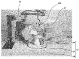
- FIG. 1 attached herewith shows an overall appearance configuration of a single crystal X-ray structure analysis apparatus including a single crystal X-ray diffraction apparatus according to an embodiment of the present invention.
- the single crystal X-ray structure analysis apparatus 1 has a base 4 that stores a cooling device and an X-ray generation power supply unit, and an X-ray protection cover 6 that is placed on the base 4.
- the anti-X-ray cover 6 has a casing 7 surrounding the single crystal X-ray diffraction device 9, a door 8 provided on the front surface of the casing 7, and the like.
- the door 8 provided on the front surface of the casing 7 can be opened, and various operations can be performed on the internal single crystal X-ray diffraction device 9 in this opened state.
- the present embodiment shown in the figure is a single crystal X-ray structure analyzing apparatus 1 including a single crystal X-ray diffracting apparatus 9 for performing structural analysis of a substance by using a crystal sponge which will be described later.
- the single crystal X-ray diffractometer 9 has an X-ray tube 11 and a goniometer 12 as shown in FIG.
- the X-ray tube 11 has a filament, a target (also referred to as “anticathode”) that is arranged to face the filament, and a casing that hermetically stores them, and the filament is It is energized by the X-ray generation power supply unit stored in the base 4 of FIG. 1 to generate heat and emit thermoelectrons. Further, a high voltage is applied between the filament and the target by the X-ray generation power supply unit, and the thermoelectrons emitted from the filament are accelerated by the high voltage and collide with the target.
- the X-ray tube 11 is configured to include an optical element such as a microfocus tube and a multilayer film condensing mirror, and can emit a beam of higher brightness. It is also possible to select from radiation sources such as Cu, Mo and Ag.
- the filament, the target arranged facing the filament, and the casing that hermetically stores them function as an X-ray source, and an optical element such as a microfocus tube and a multilayer film condensing mirror.
- the configuration for X-ray irradiation including the above functions as an X-ray irradiation unit.
- the goniometer 12 supports the sample S to be analyzed and is arranged around the ⁇ rotary table 16 and the ⁇ rotary table 16 which is rotatable around the sample axis ⁇ passing through the X-ray incident point of the sample S. And a 2 ⁇ rotary table 17 rotatable about the sample axis ⁇ .
- the sample S is occluded in the inside of a crystal sponge previously attached to a part of the sample holder 250 which will be described in detail later.
- a drive device (not shown) for driving the ⁇ rotary table 16 and the 2 ⁇ rotary table 17 described above is stored inside the base 18 of the goniometer 12, and is driven by these drive devices to drive ⁇
- the rotary table 16 rotates intermittently or continuously at a predetermined angular velocity, so-called ⁇ rotation.
- the 2 ⁇ rotation base 17 rotates intermittently or continuously, so-called 2 ⁇ rotation.
- the above drive device can be configured by any structure, for example, a power transmission structure including a worm and a worm wheel.
- An X-ray detector 22 is mounted on a part of the outer circumference of the goniometer 12, and the X-ray detector 22 is, for example, a CCD type or CMOS type two-dimensional pixel detector or a hybrid type pixel detector. Composed.
- the X-ray detection and measurement unit refers to a configuration that detects and measures X-rays diffracted or scattered by the sample, and includes the X-ray detector 22 and a control unit that controls the X-ray detector 22.
- the sample S rotates ⁇ around the sample axis ⁇ by the ⁇ rotation of the ⁇ rotary table 16 of the goniometer 12.
- X-rays generated from the X-ray focal point in the X-ray tube 11 and directed toward the sample S are incident on the sample S at a predetermined angle and are diffracted / diverged. That is, the incident angle of the X-ray incident on the sample S changes according to the ⁇ rotation of the sample S.
- the sample S When the Bragg diffraction condition is satisfied between the incident angle of the X-ray incident on the sample S and the crystal lattice plane, the sample S generates diffracted X-rays. This diffracted X-ray is received by the X-ray detector 22 and its X-ray intensity is measured. As described above, the angle of the X-ray detector 22 with respect to the incident X-ray, that is, the intensity of the diffracted X-ray corresponding to the diffraction angle is measured, and the crystal structure or the like of the sample S is analyzed from the measurement result.
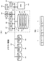
- FIG. 3 (A) shows an example of details of an electrical internal configuration of the control unit 110 in the single crystal X-ray structure analysis apparatus.
- the present invention is not limited to the embodiments described below.
- This single crystal X-ray structure analyzing apparatus 1 includes the above-mentioned internal structure, and further, a measuring apparatus 102 for measuring an appropriate substance as a sample, an input apparatus 103 composed of a keyboard, a mouse, etc., and a display.
- An image display device 104 as a means, a printer 106 as a means for printing and outputting an analysis result, a CPU (Central Processing Unit) 107, a RAM (Random Access Memory) 108, and a ROM (Read Only Memory) 109 and a hard disk 111 as an external storage medium.
- CPU Central Processing Unit
- RAM Random Access Memory
- ROM Read Only Memory
- the image display device 104 is composed of an image display device such as a CRT display or a liquid crystal display, and displays an image on the screen according to an image signal generated by the image control circuit 113.
- the image control circuit 113 generates an image signal based on the image data input thereto.
- the image data input to the image control circuit 113 is formed by the operation of various calculation means implemented by a computer including a CPU 107, a RAM 108, a ROM 109 and a hard disk 111.
- the printer 106 may be an ink plotter, a dot printer, an inkjet printer, an electrostatic transfer printer, or any other type of printing device.
- the hard disk 111 may be composed of a magneto-optical disk, a semiconductor memory, or a storage medium having any structure.
- analysis application software 116 that controls the overall operation of the single crystal X-ray structure analysis apparatus 1
- measurement application software 117 that controls the operation of measurement processing using the measurement apparatus 102
- image display The display application software 118 that controls the operation of the display process using the device 104 is stored.
- These application software realizes a predetermined function after being read from the hard disk 111 and transferred to the RAM 108 as needed.
- the single crystal X-ray structure analyzing apparatus 1 further includes, for example, a database placed in a cloud area for storing various measurement results including the measurement data obtained by the measuring apparatus 102.
- a database placed in a cloud area for storing various measurement results including the measurement data obtained by the measuring apparatus 102.
- an XRDS information database 120 that stores the XRDS image data obtained by the measuring device 102
- a microscope image database 130 that stores an actually measured image obtained by a microscope, and further, for example, , An XRF, a Raman ray, and the like, and a measurement result obtained by analysis other than X-rays
- another analysis database 140 that stores physical property information.
- these databases do not necessarily have to be installed inside the single crystal X-ray structure analysis apparatus 1, and may be provided outside and connected to each other via a network 150 or the like so that they can communicate with each other. ..
- the single crystal X-ray structure analyzing apparatus 1 controls the operation of the measurement process using the measuring apparatus 102 by the X-ray detecting and measuring unit, and detects the X-rays diffracted or scattered by the sample. Receive and manage various measurement results including the measurement data obtained in. Further, the structural analysis unit performs structural analysis of the sample based on various measurement results including measurement data obtained by detecting X-rays diffracted or scattered by the sample.
- a method of storing each measurement data in an individual file can be considered, but in the present embodiment, as shown in FIG.
- a plurality of measurement data are continuously stored in one data file.
- the storage area described as “condition” in FIG. 3B is an area for storing various pieces of information including device information when the measurement data is obtained and measurement conditions.
- Such measurement conditions include (1) measurement target substance name, (2) measurement device type, (3) measurement temperature range, (4) measurement start time, (5) measurement end time, and (6) measurement angle. Range, (7) moving speed of the scanning movement system, (8) scanning conditions, (9) type of X-rays incident on the sample, (10) whether or not an attachment such as a sample high temperature device is used, and various other conditions Can be considered.
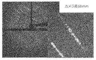
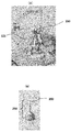
- An XRDS (X-ray Diffraction and Scattering) pattern or image (see FIG. 4) is used to detect an X-ray received on a plane that is a two-dimensional space of the X-ray detector 22 that constitutes the measurement apparatus 102. It is obtained by receiving / accumulating light for each pixel arranged in a plane which constitutes the container and measuring the intensity thereof. For example, by detecting the intensity of the received X-ray by integration for each pixel of the X-ray detector 22, a pattern or image in a two-dimensional space of r and ⁇ can be obtained.
- the XRDS pattern or image in the observation space obtained by diffraction or scattering of X-rays by the target material with respect to the irradiated X-rays reflects the information of the electron density distribution in the real space of the target material.
- the XRDS pattern is a two-dimensional space of r and ⁇ , and does not directly express the symmetry in the real space of the target material, which is a three-dimensional space. Therefore, it is generally difficult to specify the (spatial) arrangement of the atoms and molecules that make up the material using only the existing XRDS image, and requires specialized knowledge of X-ray structural analysis. Therefore, in the present embodiment, the measurement application software described above is adopted for automation.
- X-ray diffraction data measurement / processing software called “CrysAlis Pro ”, which is a platform for single crystal structure analysis, is installed, Performs preliminary measurement, setting of measurement conditions, main measurement, data processing, etc. Further, by mounting an automatic structural analysis plug-in called “AutoChem”, structural analysis and structural refinement are executed in parallel with X-ray diffraction data acquisition. Then, the structure analysis program called “Olex 2 ” also shown in FIG. 6 performs space group determination, phase determination, molecular model construction and modification, structure refinement, final report, and CIF file creation.
- a “crystal sponge” which is an extremely minute and fragile porous complex crystal with a number of pores with a diameter of 0.5 nm to 1 nm opened innumerably and having a size of about several tens ⁇ m to several hundreds ⁇ m, Due to the development of the so-called material, single crystal X-ray structural analysis is widely applied to liquid compounds that do not crystallize, or very small samples such as several ng to several ⁇ g that cannot be secured in sufficient amounts for crystallization. It is possible to do.
- the present invention has been achieved based on the findings of the inventor as described above, and a single crystal X-ray structural analysis using a crystal sponge that is extremely minute and fragile is performed by the following sample holder for crystal sponge ( It is possible to perform quickly, reliably and easily by using the sample holder mounting mechanism described below together with the applicator which is also a sample holder) and its handling (operation) instrument.
- the present invention realizes a single crystal X-ray structure analysis apparatus which has a high yield, is efficient, is excellent in versatility, and is user-friendly.
- next-generation single-crystal X-ray structure analysis apparatus an extremely minute and fragile crystal sponge that occludes an extremely small amount of sample S is prepared, and further, the sample S (crystal sponge ) Has to be taken out from the occlusion container and attached to the predetermined position of the tip of the goniometer 12 accurately and promptly in a short time so that the crystal sponge is not destroyed by drying, but there is a major limitation.
- sample S crystal sponge
- the present invention solves such a problem, that is, while using an extremely minute and fragile (fragile) difficult-to-handle crystal sponge, including mounting work of the sample occluded in the crystal sponge to the device, anyone, Device and method for performing single crystal X-ray structural analysis that is quick, reliable, easy, efficient with high yield, can be performed in a user-friendly manner, and has excellent versatility, and further an instrument therefor Are provided and are described in detail below.
- FIG. 7 (A) shows the tip of the goniometer 12 in an enlarged manner.
- a crystal sponge 200 for occluding the sample to be analyzed proposed by the present invention is attached to the tip in advance.
- FIG. 7B shows an enlarged view of a so-called sample holder 250 mounted (mounted) on the goniometer head 121 at the tip of the goniometer 12.
- the sample holder 250 is attachable / detachable to / from the goniometer head 121 at the tip of the goniometer 12 by, for example, a mounting / positioning mechanism using magnetic force, and anyone can easily and accurately mount the sample holder 250 at an accurate position. It is possible.
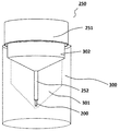
- FIG. 8 shows an overall perspective view of the sample holder 250 described above, and FIG. 9 shows its cross section.
- the sample holder 250 includes a pin (cylindrical) sample on the base portion 251 of a disc-shaped or conical holder made of metal or the like that is attached to the goniometer head 121 (see FIG. 7A) at the tip of the goniometer 12.
- a holding portion (hereinafter, also simply referred to as a holding portion) 252 (corresponding to a so-called gonio head pin) is planted in the center of one surface (lower surface in the figure) of the pin-shaped holding portion.
- the crystal sponge 200 for storing the above-described sample to be analyzed is previously fixed integrally with the sample holder 250. Further, a positioning mechanism such as a magnet (not shown) is provided on the other surface (upper surface in the drawing) of the disk-shaped base portion 251. The sample holder 250 is detachably attached to the tip of the goniometer 12 by this positioning mechanism.
- a so-called applicator 300 which is a handling (manipulation) instrument for being used together with the sample holder 250 to store the sample in the crystal sponge 200 previously attached to the sample holder, is shown. It is shown.
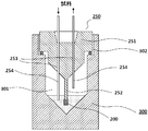
- the applicator 300 is formed of, for example, a transparent or opaque member such as glass, resin, or metal, and a storage space 301 for storing the sample holder 250 is formed therein. Further, an opening portion 302 for inserting and removing the sample holder 250 is formed on the upper portion thereof.
- a seal portion (a hatched portion in FIG. 9) is provided so as to be kept airtight from the outside in a state where the sample holder 250 is stored in the storage space 301 therein. Are shown).
- a pair of penetrating pores 253, 253 for introducing the sample to be analyzed into the crystal sponge 200 located inside the applicator 300 (storage space 301). are formed.
- the pores 253 and 253 are a preferable example of the sample introduction structure, and other structures can be adopted.
- these pores 253, 253 are also provided with a seal portion, which allows a sample introduction tube (hereinafter, simply referred to as a sample introduction tube for introducing the sample into the crystal sponge 200, as shown in the figure.
- a sample introduction tube hereinafter, simply referred to as a sample introduction tube for introducing the sample into the crystal sponge 200, as shown in the figure.
- the storage space 301 inside the applicator 300 is kept airtight even when the introduction pipes 254 and 254 are inserted into the pores 253 and 253.
- a part of the sample holder 250 is configured.
- the crystal sponge 200 attached to the tip of the pin-shaped holding portion 252 (corresponding to a goniometer head pin) can be safely and easily handled without being damaged or departing from the sample holder 250. That is, the crystal sponge 200 that has occluded a very small amount of sample is taken out from the occluding container as a single unit as in the conventional case and is not damaged, and is safe, simple and easy, and in a short time not to be destroyed by drying. , Can be quickly prepared on the gonio head 121.
- the sample holder 250 whose occlusion of the sample has been completed is removed from the applicator 300 and attached to the goniometer head 121 (see FIG. 7A) at the tip of the goniometer 12.
- the sample S occluded in the crystal sponge 200 can be easily, accurately and quickly arranged at a predetermined position in the single crystal X-ray diffractometer 9 without requiring highly specialized knowledge or precise work. Will be done.
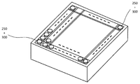
- sample holders 250 are integrated (unitized) with the applicator 300 which is a handling (operating) instrument, and as shown in FIG. It could be housed in a case and provided as a so-called set.
- sample holder 250 and the applicator 300 may be provided as a unit (unit) or as a set, as described above.
- FIG. 11 conceptually shows a single crystal X-ray structure analysis method using a sample holder 250, which is an embodiment of the present invention.
- a very small amount of sample is introduced into the sample holder 250 provided integrally (unit) with the applicator 300, and necessary occlusion is performed.
- a pair of sample introductions are made to the pair of penetrating pores 253 and 253 (see FIG. 9) formed in the sample holder 250.
- the tubes 254 and 254 the sample can be occluded in the crystal sponge 200 attached to the tip of the sample holder 250.
- LC liquid chromatography
- GC gas chromatography
- SCF supercritical fluid chromatography
- the sample is sent from the supply-side pipe to the supply-side sample introduction pipe 254, and is supplied from the tip portion of the supply-side sample introduction pipe 254 to the sample holder 250 inside the applicator 300.
- a sample alone or a solution in which a sample and a storage solvent (carrier) are mixed is supplied through the sample introduction tube 254 on the supply side.
- the introduced minute amount of the sample S comes into contact with the crystal sponge 200 attached to the tip of the pin-shaped holding portion 252 of the sample holder 250 in the storage space 301 of the applicator 300 to occlude the sample. Is done.
- the electrophoresis device here includes various electrophoresis devices such as capillary electrophoresis and isoelectric focusing.
- an excess sample or a solution in which a sample and a storage solvent (carrier) are mixed is discharged from the sample introduction pipe 254 on the discharge side after a predetermined time has elapsed while the sample is injected. To be done.
- unnecessary storage solvent (carrier) or solution flows in the sample introduction pipe 254 on the discharge side and is discharged. Therefore, the sample may not flow into the sample introduction pipe 254 on the discharge side.
- gas or supercritical fluid is used as the carrier, the carrier containing the sample is discharged.
- the sample holder 250 that has completed this occlusion process is removed from the applicator 300, and is placed at a predetermined position in the single crystal X-ray diffraction apparatus 9, that is, at the tip of the goniometer head pin of the goniometer 121 at the tip of the goniometer 12.
- the X-ray beam from the corresponding X-ray tube 11 is accurately attached to a position where the X-ray beam is condensed and irradiated, for example, by using the sample holder attaching mechanism described below and the above-described positioning mechanism such as magnetic force.
- FIG. 13 is a configuration of a sample holder attachment mechanism 600 for removing the sample holder 250 to which the crystal sponge 200 whose occlusion has been completed is attached from the applicator 300 and attaching (mounting) it to the goniometer head 121 at the tip of the goniometer 12. Shows an example. As shown in the figure, the sample holder attachment mechanism 600 is arranged in parallel with each other, and moves close to or away from each other (see the arrow in the figure) while the base portion 251 of the sample holder 250 is moved between them.
- a sample holder grip 610 including a pair of rod-shaped grips 611, 611 for holding / releasing, and also arranged parallel to each other and movable toward and away from each other (see arrow in the figure), in between.
- An applicator grip 620 including a pair of rod-shaped members 621 and 621 that holds / releases the applicator 300.
- the former sample holder gripping portion 610 is configured to further rotate itself and move its position toward the goniometer 121 of the goniometer 12 as shown by an arrow in the figure. From the function of the sample holder mounting mechanism 600, it is preferable that the sample holder mounting mechanism 600 is arranged at a position close to the goniometer 12 in the single crystal X-ray diffraction apparatus 9.
- the sample holder attachment mechanism 600 may be arranged outside the single crystal X-ray diffraction device 9, such as the storage device 500 or between the storage device 500 and the single crystal X-ray diffraction device 9.
- the base holder 251 of the sample holder 250 is grasped by the sample holder grasping portion 610, and at the same time, the applicator 300 is grasped by the applicator grasping portion 620, and then the sample holder grasping portion is indicated by an arrow in FIG. 610 moves in a direction in which the gripped sample holder 250 is detached from the applicator 300, for example, in the vertical direction here, more specifically, in the extension direction of the pin-shaped holding portion 252.
- the sample holder 250 can be safely applied to the sample holder 250 without the crystal sponge 200 attached to the tip of the pin-shaped holding portion 252 coming into contact with a part of the applicator 300 and being damaged or deviated. Can be removed from the computer 300.
- the sample holder gripping part 610 is attached to the tip of the goniometer head 121 of the goniometer 12 in a state in which the sample holder gripping part 610 is rotated up and down (see the arrow in the figure) and turned upside down.
- the sample holder gripping portion 610 moves to the position of the goniometer head 121 while holding the outer periphery of the base 251 (or applicator 300), and rotates. Then, the sample holder 250 integrated with the applicator 300 may be mounted on the gonio head 121. In this case, thereafter, the applicator gripping portion 620 grips the outer periphery of the applicator 300, and at the same time, the sample holder gripping portion 610 grips the base portion 251 and stands still.
- the crystal sponge 200 can be safely removed from the applicator 300 and attached to the tip of the goniometer head 121 without abutting against a part of the applicator 300 and damaging or deviating, similarly to the above. Can be installed.
- the sample holder gripping portion 610 and the applicator gripping portion 620 are each described as being composed of a pair of parallel-movable rod-shaped members. However, these gripping portions are the sample holder or the applicator.
- a grasping means such as a so-called robot arm. That would be obvious.
- the crystal sponge 200 attached to a part (tip) of the pin-shaped holding portion 252 of the sample holder 250 attached to the tip of the goniometer 121 of the goniometer 12 is stored in the sample holder 250 after the occlusion is completed. Even when removing from the applicator 300, the position where the X-ray beam from the X-ray tube 11 is focused and radiated accurately and safely can be contacted with other parts without being damaged or deviated. Will be placed in. In other words, the sample occluded in the crystal sponge 200 is accurately, quickly and safely arranged at a predetermined position in the X-ray diffractometer 9, and then the sample S is sampled by the single crystal X-ray diffractometer. The intensity of the diffracted X-ray from is measured, and its crystal structure and the like are analyzed.
- the sample holder 250, the applicator 300, and the sample holder mounting mechanism 600 of the present invention anyone can easily and safely integrate a very small amount of sample in advance into the sample holder 250.
- the crystal sponge 200 having a very small size attached thereto is occluded, and then the sample S is accurately and accurately placed on the goniometer 12 in a short time, quickly and safely so that the crystal sponge is not destroyed by drying. It becomes possible to mount it.
- a single crystal X-ray structure analysis device that is highly versatile and that can perform a single crystal X-ray structure analysis using a crystal sponge efficiently with good yield, and that also includes automation of mounting a sample holder. Will be provided.
- the present invention is not limited to the above-described embodiments and includes various modifications.
- the above-described embodiment is a detailed description of the entire system in order to explain the present invention in an easy-to-understand manner, and is not necessarily limited to one having all the configurations described.
- part of the configuration of one embodiment can be replaced with the configuration of another embodiment, and the configuration of another embodiment can be added to the configuration of one embodiment. It would be possible to add, delete, or replace some of the example configurations with other configurations.
- the present invention can be widely used in a method for searching a material structure, an X-ray structure analysis apparatus used for the method, and the like.
Landscapes
- Chemical & Material Sciences (AREA)
- Crystallography & Structural Chemistry (AREA)
- Physics & Mathematics (AREA)
- Health & Medical Sciences (AREA)
- Life Sciences & Earth Sciences (AREA)
- Analytical Chemistry (AREA)
- Biochemistry (AREA)
- General Health & Medical Sciences (AREA)
- General Physics & Mathematics (AREA)
- Immunology (AREA)
- Pathology (AREA)
- Analysing Materials By The Use Of Radiation (AREA)
Abstract
結晶スポンジに吸蔵した試料の取り外しや装置への搭載作業を確実かつ容易に行うことが可能な単結晶X線構造解析装置および試料ホルダ取り付け装置を提供する。物質の構造解析を行う単結晶X線構造解析装置に試料を保持する試料ホルダを取り付ける試料ホルダ取り付け装置であって、着脱可能なアプリケータ300に装着されて提供された前記試料ホルダ250を、前記単結晶X線構造解析装置のゴニオメータ12に、前記試料ホルダ250を前記アプリケータ300から取り外した状態で取り付ける試料ホルダ取付け機構600を備え、前記試料ホルダ250は、内部に形成された複数の微細孔に前記試料を吸蔵可能な細孔性錯体結晶を含み、前記細孔性錯体結晶は、前記試料ホルダ250が前記ゴニオメータ12に取り付けられた状態で、前記試料ホルダ250の前記X線照射部からのX線が照射される位置に固定されている。
Description
本発明は、材料の構造をその原子や分子の配列などのミクロな集合構造によって解析することを可能にする次世代の単結晶X線構造解析装置に関し、特に、解析する対象となる単結晶試料の装置への搭載をも含めた単結晶X線構造解析装置および試料ホルダ取り付け装置の構成に関する。
新たなデバイスや材料の研究開発では、日常的に材料の合成、材料の評価、それに基づいた次の研究方針の決定が行なわれている。短期間に材料開発を行うためのX線回折を用いた物質の構造解析では、目的の材料の機能・物性を実現する物質構造を効率良く探索するために、構造解析を効率的に行うことを可能とする物質の構造解析を中心とした物質構造の探索方法とそれに用いるX線構造解析は必要不可欠である。
しかし、当該手法で得られた結果に基づいて構造解析を行うことは、X線の専門家でなければ難しかった。そのため、X線の専門家でなくても構造解析を行うことができるX線構造解析システムが求められていた。その中でも、特に、以下の特許文献1にも知られるように、単結晶X線構造解析は、正確で精度の高い分子の立体構造を得ることができる手法として注目されている。
他方、この単結晶X線構造解析には、試料を結晶化して単結晶を用意しなければならないという大きな制約があった。しかしながら、以下の非特許文献1や2、更には、特許文献2にも知られるように、「結晶スポンジ」と呼ばれる材料(例えば、直径0.5nmから1nmの細孔が無数に開いた細孔性錯体結晶)の開発によって、結晶化しない液体状化合物や結晶化を行うに足る量を確保できない試料なども含め、単結晶X線構造解析を広く適用することが可能となっている。
Makoto Fujita; X-ray analysis on the nanogram to microgram scale using porous complexes; Nature 495, 461-466; 28 March 2013
Hoshino et al. (2016), The updated crystalline sponge method IUCrJ, 3, 139-151
しかしながら、上述した結晶スポンジを利用した従来技術になる単結晶X線構造解析では、各種の装置によって分離された数ng~数μg程度の極微量の試料を寸法100μm程度の極微小で脆弱(fragile)な結晶スポンジの骨格内に吸蔵する工程と共に、更に、この試料を吸蔵した極微小な結晶スポンジを取り出し、器具に取り付け、単結晶X線構造解析装置内のX線照射位置に搭載するという微細で緻密な作業を伴う工程を、迅速かつ正確に行うことを必要とする。なお、これらの短時間で行う微細かつ緻密な作業は、結晶スポンジに吸蔵した後の試料の測定結果に多大な影響を及ぼすこととなり、非常に重要な作業となる。
このことから、本発明は、上述した従来技術における問題点に鑑みて達成されたものであり、その目的は、特に、X線構造解析の専門知識がなくても、本発明により提案される試料ホルダの利用を含めて、結晶スポンジによる単結晶X線構造解析における試料を吸蔵した極微細で脆弱(fragile)な結晶スポンジを取り出して装置内のX線照射位置に搭載する作業を、迅速に、かつ、確実かつ容易に行うことを可能とする、換言すれば、歩留まり良くかつ効率的で、汎用性に優れ、かつ、試料ホルダの搭載の自動化を含むユーザフレンドリな単結晶X線構造解析装置を提供することにある。
(1)物質の構造解析を行う単結晶X線構造解析装置に試料を保持する試料ホルダを取り付ける試料ホルダ取り付け装置であって、着脱可能なアプリケータに装着されて提供された前記試料ホルダを、前記単結晶X線構造解析装置のゴニオメータに、前記試料ホルダを前記アプリケータから取り外した状態で取り付ける試料ホルダ取付け機構を備え、前記試料ホルダは、内部に形成された複数の微細孔に前記試料を吸蔵可能な細孔性錯体結晶を含み、前記細孔性錯体結晶は、前記試料ホルダが前記ゴニオメータに取り付けられた状態で、前記試料ホルダの前記X線照射部からのX線が照射される位置に固定されていることを特徴としている。
(2)また、本発明の試料ホルダ取り付け装置において、前記試料ホルダ取付け機構は、前記試料ホルダを把持する試料ホルダ把持部と、前記アプリケータを把持するアプリケータ把持部と、を備え、前記試料ホルダ把持部または前記アプリケータ把持部の少なくとも一方は、前記試料ホルダ把持部が前記試料ホルダを把持した状態で、前記アプリケータ把持部が把持している前記アプリケータから前記試料ホルダを取り外す方向に移動可能であることを特徴としている。
(3)また、本発明の試料ホルダ取り付け装置において、前記試料ホルダ把持部は、前記試料ホルダの前記細孔性錯体結晶を取り付けたピン状の保持部の延長方向に移動可能であることを特徴としている。
(4)また、本発明の試料ホルダ取り付け装置において、前記試料ホルダ把持部は、前記試料ホルダを把持した状態で、回動可能であることを特徴としている。
(5)また、本発明の試料ホルダ取り付け装置において、前記試料ホルダ把持部は、前記試料ホルダを把持した状態で、前記ゴニオメータの試料ホルダ取付け位置に前記試料ホルダを取り付ける方向に移動可能であることを特徴としている。
(6)また、本発明の単結晶X線構造解析装置は、物質の構造解析を行う単結晶X線構造解析装置であって、X線を発生するX線源と、前記試料ホルダと、前記試料ホルダを取り付けて回動するゴニオメータと、前記ゴニオメータに取り付けられた前記試料ホルダに保持された前記試料に対して前記X線源からのX線を照射するX線照射部と、前記試料により回折又は散乱されたX線を検出して測定するX線検出測定部と、前記X線検出測定部に検出された回折又は散乱X線に基づいて前記試料の構造解析を行なう構造解析部と、(1)から(4)のいずれか一項に記載の試料ホルダ取り付け装置と、を備えることを特徴としている。
上述した本発明によれば、本発明により提案される試料ホルダやアプリケータと共に、その取付け機構を利用することにより、迅速性も必要とされる従来の緻密でかつ微細な作業を伴わず、微量の試料を吸蔵させた後の極微小で脆弱(fragile)な結晶スポンジへ試料の吸蔵とその後の装置への搭載等を含む一連の作業を、迅速に、かつ確実かつ容易に行うことが出来る、換言すれば、歩留まり良くかつ効率的で、汎用性にも優れ、かつ、試料ホルダの搭載の自動化を含むユーザフレンドリな単結晶X線構造解析装置が提供される。このことから、結晶スポンジによる単結晶X線構造解析を容易に利用可能にして、広く普及させることが可能となる。
以下、本発明の一実施の形態になる、結晶スポンジを利用した単結晶X線構造解析装置について、添付の図面を参照しながら、詳細に説明する。なお、本出願において「AまたはB」の表現は、「AおよびBの少なくとも一方」を意味し、AおよびBがありえないという特段の事情がない限り「AおよびB」を含む。
添付の図1には、本発明の一実施の形態になる、単結晶X線回折装置を含む単結晶X線構造解析装置の全体外観構成が示されており、図からも明らかなように、単結晶X線構造解析装置1は、冷却装置やX線発生電源部を格納した基台4と、その基台4の上に載置された防X線カバー6とを有する。
防X線カバー6は、単結晶X線回折装置9を包囲するケーシング7及びそのケーシング7の前面に設けられた扉8等を有する。ケーシング7の前面に設けられた扉8は開くことができ、この開いた状態で内部の単結晶X線回折装置9に対して種々の操作を行うことができる。なお、図に示す本実施形態は、後にも述べる結晶スポンジを利用して物質の構造解析を行う単結晶X線回折装置9を含んだ単結晶X線構造解析装置1である。
単結晶X線回折装置9は、図2にも示すように、X線管11及びゴニオメータ12を有する。X線管11は、ここでは図示しないが、フィラメントと、フィラメントに対向して配置されたターゲット(「対陰極」とも言う)と、それらを気密に格納するケーシングとを有し、このフィラメントは、図1の基台4に格納されたX線発生電源部によって通電されて発熱して熱電子を放出する。また、フィラメントとターゲットとの間にはX線発生電源部によって高電圧が印加され、フィラメントから放出された熱電子が高電圧によって加速されてターゲットに衝突する。この衝突領域がX線焦点を形成し、このX線焦点からX線が発生して発散する。より詳細には、このX線管11は、ここでは図示しないが、マイクロフォーカス管と多層膜集光ミラー等の光学素子を含んで構成されており、より高い輝度のビームを照射することが可能であり、また、Cu、MoやAgなどの線源から選択可能となっている。上記に例示するように、フィラメントと、フィラメントに対向して配置されたターゲットと、それらを気密に格納するケーシングが、X線源として機能し、マイクロフォーカス管と多層膜集光ミラー等の光学素子を含むX線照射のための構成がX線照射部として機能する。
また、ゴニオメータ12は、解析すべき試料Sを支持すると共に、試料SのX線入射点を通る試料軸線ωを中心として回転可能とするθ回転台16と、θ回転台16のまわりに配置されて試料軸線ωを中心として回転可能な2θ回転台17とを有する。なお、試料Sは、本実施形態の場合、後にも詳述する試料ホルダ250の一部に予め取り付けられた結晶スポンジの内部に吸蔵されている。ゴニオメータ12の基台18の内部には、上述したθ回転台16及び2θ回転台17を駆動するための駆動装置(図示せず)が格納されており、これらの駆動装置によって駆動されて、θ回転台16は所定の角速度で間欠的又は連続的に回転し、いわゆるθ回転する。また、これらの駆動装置によって駆動されて2θ回転台17は間欠的又は連続的に回転し、いわゆる2θ回転する。上記の駆動装置は任意の構造によって構成できるが、例えば、ウォームとウォームホイールとを含んで構成される動力伝達構造によって構成できる。
ゴニオメータ12の外周の一部にはX線検出器22が載置されており、このX線検出器22は、例えば、CCD型やCMOS型の2次元ピクセル検出器、ハイブリッド型ピクセル検出器などによって構成される。なお、X線検出測定部は、試料により回折又は散乱されたX線を検出して測定する構成を指し、X線検出器22およびこれを制御する制御部を含む。
単結晶X線回折装置9は、以上のように構成されているので、試料Sは、ゴニオメータ12のθ回転台16のθ回転によって試料軸線ωを中心としてθ回転する。この試料Sがθ回転する間、X線管11内のX線焦点から発生して試料Sへ向けられるX線は所定の角度で試料Sに入射して回折・発散する。即ち、試料Sへ入射するX線の入射角度は試料Sのθ回転に応じて変化する。
試料Sに入射するX線の入射角度と結晶格子面との間でブラッグの回折条件が満足されると、その試料Sから回折X線が発生する。この回折X線はX線検出器22に受光されてそのX線強度が測定される。以上により、入射X線に対するX線検出器22の角度、すなわち回折角度に対応する回折X線の強度が測定され、この測定結果から試料Sに関する結晶構造等が解析される。
続いて、図3(A)は、上記単結晶X線構造解析装置における制御部110を構成する電気的な内部構成の詳細の一例を示す。なお、本発明が以下に述べる実施形態に限定されるものでないことは、もちろんである。
この単結晶X線構造解析装置1は、上述した内部構成を含んでおり、更に、適宜の物質を試料として測定を行う測定装置102と、キーボード、マウス等によって構成される入力装置103と、表示手段としての画像表示装置104と、解析結果を印刷して出力するための手段としてのプリンタ106と、CPU(Central Processing Unit)107と、RAM(Random Access Memory)108と、ROM(Read Only Memory)109と、外部記憶媒体としてのハードディスク111などを有する。これらの要素はバス112によって電気的に相互につながれている。
画像表示装置104は、CRTディスプレイ、液晶ディスプレイ等といった画像表示機器によって構成されており、画像制御回路113によって生成される画像信号に従って画面上に画像を表示する。画像制御回路113はこれに入力される画像データに基づいて画像信号を生成する。画像制御回路113に入力される画像データは、CPU107、RAM108、ROM109及びハードディスク111を含んで構成されるコンピュータによって実現される各種の演算手段の働きによって形成される。プリンタ106は、インクプロッタ、ドットプリンタ、インクジェットプリンタ、静電転写プリンタ、その他任意の構造の印刷用機器を用いることができる。なお、ハードディスク111は、光磁気ディスク、半導体メモリ、その他、任意の構造の記憶媒体によって構成することもできる。
ハードディスク111の内部には、単結晶X線構造解析装置1の全般的な動作を司る分析用アプリケーションソフト116と、測定装置102を用いた測定処理の動作を司る測定用アプリケーションソフト117と、画像表示装置104を用いた表示処理の動作を司る表示用アプリケーションソフト118とが格納されている。これらのアプリケーションソフトは、必要に応じてハードディスク111から読み出されてRAM108へ転送された後に所定の機能を実現する。
この単結晶X線構造解析装置1は、更に、上記測定装置102によって得られた測定データを含めた各種の測定結果を記憶するための、例えば、クラウド領域に置かれたデータベースも含んでいる。図の例では、後にも説明するが、上記の測定装置102によって得られたXRDSイメージデータを格納するXRDS情報データベース120、顕微鏡により得られた実測イメージを格納する顕微鏡イメージデータベース130、更には、例えば、XRFやラマン光線等、X線以外の分析により得られた測定結果や、物性情報を格納するその他分析データベース140が示されている。なお、これらのデータベースは、必ずしも、単結晶X線構造解析装置1の内部に搭載される必要はなく、例えば、外部に設けられてネットワーク150等を介して相互に通信可能に接続されてもよい。このようにして、単結晶X線構造解析装置1は、X線検出測定部により、測定装置102を用いた測定処理の動作を制御するとともに、試料により回折又は散乱されたX線を検出することで得られた測定データを含めた各種の測定結果を受け取り、管理する。また、構造解析部により、試料により回折又は散乱されたX線を検出することで得られた測定データを含めた各種の測定結果に基づいて試料の構造解析を行なう。
データファイル内に複数の測定データを記憶するためのファイル管理方法としては、個々の測定データを個別のファイル内に格納する方法も考えられるが、本実施形態では、図3(B)に示すように、複数の測定データを1つのデータファイル内に連続して格納することとしている。なお、図3(B)において「条件」と記載された記憶領域は、測定データが得られたときの装置情報および測定条件を含む各種の情報を記憶するための領域である。
このような測定条件としては、(1)測定対象物質名、(2)測定装置の種類、(3)測定温度範囲、(4)測定開始時刻、(5)測定終了時刻、(6)測定角度範囲、(7)走査移動系の移動速度、(8)走査条件、(9)試料に入射するX線の種類、(10)試料高温装置等といったアタッチメントを使ったか否か、その他、各種の条件が考えられる。
XRDS(X-ray Diffraction and Scattering)パターン又はイメージ(図4を参照)は、上記測定装置102を構成するX線検出器22の2次元空間である平面上で受け取られたX線を、当該検出器を構成する平面状に配列された画素毎に受光/蓄積して、その強度を測定することにより得られるものである。例えば、X線検出器22の各画素毎に、積分によって受光したX線の強度を検出することによれば、rとθの2次元空間上のパターン又はイメージが得られる。
<測定用アプリケーションソフト>
照射されるX線に対する対象材料によるX線の回折や散乱によって得られる観測空間上のXRDSパターン又はイメージは、対象材料の実空間における電子密度分布の情報を反映している。しかしながら、XRDSパターンは、rとθの2次元空間であり、3次元空間である対象材料の実空間における対称性を直接的に表現するものではない。そのため、一般的に、現存のXRDSイメージだけでは、材料を構成する原子や分子の(空間)配列を特定することは困難であり、X線構造解析の専門知識を必要とする。そのため、本実施例では、上述した測定用アプリケーションソフトを採用して自動化を図っている。
照射されるX線に対する対象材料によるX線の回折や散乱によって得られる観測空間上のXRDSパターン又はイメージは、対象材料の実空間における電子密度分布の情報を反映している。しかしながら、XRDSパターンは、rとθの2次元空間であり、3次元空間である対象材料の実空間における対称性を直接的に表現するものではない。そのため、一般的に、現存のXRDSイメージだけでは、材料を構成する原子や分子の(空間)配列を特定することは困難であり、X線構造解析の専門知識を必要とする。そのため、本実施例では、上述した測定用アプリケーションソフトを採用して自動化を図っている。
その一例として、図5(A)及び(B)にその実行画面を示すように、単結晶構造解析のためのプラットフォームである「CrysAlisPro」と呼ばれるX線回折データ測定・処理ソフトウェアを搭載し、予備測定、測定条件の設定、本測定、データ処理などを実行する。更には、「AutoChem」と呼ばれる自動構造解析プラグインを搭載することにより、X線回折データ収集と並行して、構造解析および構造の精密化を実行する。そして、図6にも示す「Olex2」と呼ばれる構造解析プログラムにより、空間群決定から位相決定、分子モデルの構築と修正、構造の精密化、最終レポート、CIFファイルの作成を行う。
以上、単結晶X線構造解析装置1の全体構造やその機能について述べたが、以下には、特に、本発明に係る結晶スポンジと、それに関連する装置や器具について、添付の図面を参照しながら詳細に述べる。
<結晶スポンジ>
上述したように、内部に直径0.5nmから1nmの細孔が無数に開いた、寸法が数10μm~数100μm程度の極微小で脆弱(fragile)な細孔性錯体結晶である「結晶スポンジ」と呼ばれる材料の開発によって、単結晶X線構造解析は、結晶化しない液体状化合物や、或いは、結晶化を行うに足る量が確保できない数ng~数μgの極微量の試料なども含め、広く適用することが可能となっている。
上述したように、内部に直径0.5nmから1nmの細孔が無数に開いた、寸法が数10μm~数100μm程度の極微小で脆弱(fragile)な細孔性錯体結晶である「結晶スポンジ」と呼ばれる材料の開発によって、単結晶X線構造解析は、結晶化しない液体状化合物や、或いは、結晶化を行うに足る量が確保できない数ng~数μgの極微量の試料なども含め、広く適用することが可能となっている。
しかしながら、現状においては、上述した結晶スポンジの骨格内への試料の結晶化である吸蔵(post-crystallization)を行うためには、各種の前処理(分離)装置によって分離された数ng~数μg程度の極微量の試料を、既に述べたように、容器内において、シクロヘキサン等の保存溶媒(キャリア)に含浸して提供される外径100μm程度の極微小で脆弱(fragile)な結晶スポンジの骨格内に吸蔵させる工程が必要となる。更には、その後、この試料を吸蔵した極微小で脆弱(fragile)な取り扱い難い結晶スポンジを、迅速に(結晶スポンジが乾燥により破壊されない程度の短い時間で)、容器から取り出し、単結晶X線回折装置内のX線照射位置に、より具体的には、ゴニオメータ12の試料軸(所謂、ゴニオヘッドピン)の先端部に、センタリングを行いながら正確に搭載する工程を必要とする。これらの工程は、X線構造解析の専門知識の有無に関わらず、作業者に非常な緻密性を要求する微細で、かつ、迅速性をも要求する作業であり、結晶スポンジに吸蔵した後の試料の測定結果に多大な影響を及ぼすこととなる。即ち、これらの作業が極微小な結晶スポンジを利用した単結晶X線構造解析を歩留まりの悪いものとしており、このことが、結晶スポンジを利用した単結晶X線構造解析が広く利用されることから阻害される一因ともなっている。
本発明は、上述したような発明者の知見に基づいて達成されたものであり、極微小で脆弱(fragile)な結晶スポンジによる単結晶X線構造解析を、以下に述べる結晶スポンジ用試料ホルダ(単に、試料ホルダともいう)やその取扱い(操作)器具であるアプリケータと共に、以下にも述べる試料ホルダ取付け機構を用いることにより、迅速に、確実かつ容易に行うことを可能とするものであり、換言すれば、歩留まり良くかつ効率的で、汎用性に優れ、かつ、ユーザフレンドリな単結晶X線構造解析装置を実現するものである。即ち、本発明に係る次世代の単結晶X線構造解析装置では、極微量な試料Sを吸蔵した極微小で脆弱(fragile)な結晶スポンジを用意すると共に、更には、当該試料S(結晶スポンジ)を吸蔵容器から取り出して、結晶スポンジが乾燥により破壊されない程度の短時間で、迅速に、ゴニオメータ12の先端部の所定位置に、正確かつ迅速に取り付けなければならないという、大きな制約があるが、特に、汎用性にも優れた試料ホルダの搭載の自動化を含むユーザフレンドリな装置を実現するためには、かかる作業を、高度な専門知識や作業の緻密性を要求せずに、迅速かつ容易に実行可能なものとする必要がある。
本発明は、かかる課題を解消し、即ち、極微小で脆弱(fragile)な取り扱い難い結晶スポンジを使用しながらも、当該結晶スポンジに吸蔵した試料の装置への搭載作業をも含め、誰でも、迅速かつ確実かつ容易に、歩留まり良く効率的で、ユーザフレンドリに行うことが可能で、かつ、汎用性にも優れた単結晶X線構造解析を行うための装置や方法、更には、そのための器具を提供するものであり、以下に詳述する。
図7(A)は、ゴニオメータ12の先端部を拡大して示しており、この図では、本発明により提案される解析すべき試料を吸蔵する結晶スポンジ200をその先端部に予め取り付けた器具である、図7(B)に拡大図を示した、所謂、試料ホルダ250が、ゴニオメータ12の先端部のゴニオヘッド121に取り付けられる(マウントされる)様子を示している。なお、この試料ホルダ250は、例えば、磁力などを利用した取付け/位置決め機構によって、ゴニオメータ12の先端部のゴニオヘッド121に対して着脱可能で、かつ、誰でも正確な位置に容易かつ高精度に取り付けることが可能となっている。
<結晶スポンジ用試料ホルダとアプリケータ>
図8は、上述した試料ホルダ250の全体斜視図を、そして、図9はその断面を示している。試料ホルダ250は、ゴニオメータ12の先端部のゴニオヘッド121(図7(A)参照)に取り付けられる金属等からなる円盤状又は円錐状のホルダの基台部251には、ピン(円柱)状の試料保持部(以下、単に保持部ともいう)252(所謂、ゴニオヘッドピンに対応する)が、その一方の面(図では下面)の中央部に植立されており、かつ、このピン状の保持部252の先端の所定の位置には、上述した解析すべき試料を吸蔵するための結晶スポンジ200が、予め試料ホルダ250と一体に取り付けて固定されている。また、円盤状の基台部251の他の面(図では上面)には、図示しないマグネット等の位置決め機構等が設けられている。この位置決め機構により試料ホルダ250は、ゴニオメータ12の先端部に着脱自在に取り付けられる。
図8は、上述した試料ホルダ250の全体斜視図を、そして、図9はその断面を示している。試料ホルダ250は、ゴニオメータ12の先端部のゴニオヘッド121(図7(A)参照)に取り付けられる金属等からなる円盤状又は円錐状のホルダの基台部251には、ピン(円柱)状の試料保持部(以下、単に保持部ともいう)252(所謂、ゴニオヘッドピンに対応する)が、その一方の面(図では下面)の中央部に植立されており、かつ、このピン状の保持部252の先端の所定の位置には、上述した解析すべき試料を吸蔵するための結晶スポンジ200が、予め試料ホルダ250と一体に取り付けて固定されている。また、円盤状の基台部251の他の面(図では上面)には、図示しないマグネット等の位置決め機構等が設けられている。この位置決め機構により試料ホルダ250は、ゴニオメータ12の先端部に着脱自在に取り付けられる。
また、図8および図9には、試料ホルダ250と共に使用されて、当該試料ホルダに予め取り付けられた結晶スポンジ200に試料を吸蔵させるための取扱い(操作)器具である、所謂、アプリケータ300が示されている。このアプリケータ300は、例えば、ガラスや樹脂や金属等の透明又は不透明な部材で形成されており、その内部には、上記の試料ホルダ250を収納するための収納空間301が形成されており、更に、その上部には、試料ホルダ250を嵌入し、かつ、取り出すための開口部302が形成されている。
更に、アプリケータ300の開口部302の一部には、その内部の収納空間301に試料ホルダ250を収納した状態で外部から気密に保たれるよう、例えば、シール部(図9中に斜線部で示す)が設けられている。他方、試料ホルダ250の基台部251には、アプリケータ300の内部(収納空間301)に位置する結晶スポンジ200に対して解析すべき試料を導入するための一対の貫通した細孔253、253が形成されている。細孔253、253は、試料導入構造の好ましい一例であり、その他の構造も採られうる。なお、図示しないが、これらの細孔253、253にもシール部が設けられており、これにより、図にも示すように、試料を結晶スポンジ200に導入するための試料導入管(以下、単に導入管ともいう)254、254が当該細孔253、253に挿入された状態でも、アプリケータ300内部の収納空間301は気密状態に保たれる。
このような構成の試料ホルダ250によれば、又は、更にその取り扱い(操作)器具であるアプリケータ300と一体化(ユニット化)して提供することによって、当該試料ホルダ250の一部を構成するピン状の保持部252(ゴニオヘッドピンに対応)の先端部に取り付けた結晶スポンジ200を、破損し、或いは、試料ホルダ250から逸脱することなく、安全かつ容易に取り扱うことができる。即ち、極微量な試料を吸蔵した当該結晶スポンジ200を、従来のように吸蔵容器から単体で取り出されて損傷することなく、安全で簡単かつ容易に、かつ、乾燥により破壊されない程度の短時間で、迅速に、ゴニオヘッド121上に準備することができる。本実施例では、この試料の吸蔵が完了した試料ホルダ250を、アプリケータ300から取り外し、ゴニオメータ12の先端部のゴニオヘッド121(図7(A)を参照)に取り付ける。これにより、結晶スポンジ200に吸蔵した当該試料Sは、高度な専門知識や緻密な作業を必要とすることなく、単結晶X線回折装置9内の所定の位置に容易に、正確かつ迅速に配置されることとなる。
また、解析すべき試料を結晶スポンジ200に導入する際、以下にも一例を示す吸蔵装置(ソーキングマシン)を利用することにより、より具体的には、当該装置からの一対の試料導入管254、254を貫通した細孔253、253に挿入し、上述した極微小な結晶スポンジ200に対して極微量な試料を導入して、必要な結晶スポンジ200への吸蔵を行うことも可能である。また、試料ホルダ250は、その取扱い(操作)器具であるアプリケータ300と共に一体化(ユニット化)し、更には、図10にも示すように、解析作業に必要な数だけ揃えて箱状のケースに収納し、所謂、セットとして提供することも可能であろう。
<結晶スポンジ用試料ホルダを用いた単結晶X線構造解析方法>
続いて、結晶スポンジ200が予め取り付けられた試料ホルダ250を用いることによって実行される単結晶X線構造解析方法について、以下に説明する。なお、試料ホルダ250とアプリケータ300とは、上述したように、一体(ユニット)として、或いは、セットとして提供されてもよい。
続いて、結晶スポンジ200が予め取り付けられた試料ホルダ250を用いることによって実行される単結晶X線構造解析方法について、以下に説明する。なお、試料ホルダ250とアプリケータ300とは、上述したように、一体(ユニット)として、或いは、セットとして提供されてもよい。
図11は、本発明の一実施例である、試料ホルダ250を用いた単結晶X線構造解析方法を概念化して示している。かかる方法では、上述したように、アプリケータ300と共に一体(ユニット)で提供される試料ホルダ250に対し、極微量な試料を導入して、必要な吸蔵を行う。その際、上記の例では、試料ホルダ250をアプリケータ300内に収納した状態で、試料ホルダ250に形成した一対の貫通した細孔253、253(図9を参照)に対して一対の試料導入管254、254を挿入することによって、試料を試料ホルダ250の先端に取り付けた結晶スポンジ200に吸蔵させることができる。
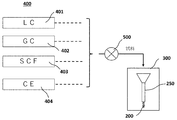
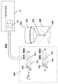
より具体的には、図12にも示すように、例えば、前処理装置400を構成するLC(液体クロマトグラフィ)401、GC(気体クロマトグラフィ)402、更には、SCF(超臨界流体クロマトグラフィ)403やCE(電気泳動)404等によって抽出された極微量な試料Sは、その担体(キャリア)と共に、各種の切替弁や調圧装置を備えて必要な条件(流量や圧力)で流体を供給する吸蔵装置(ソーキングマシン)500を介して、試料ホルダ250の細孔253、253に挿入される一対の試料導入管254、254(図9を参照)に供給され、当該試料はアプリケータ300内部の収納空間301に選択的に導入される。すなわち試料は、供給側配管から供給側の試料導入管254に送られ、供給側の試料導入管254の先端部分からアプリケータ300の内部の試料ホルダ250に供給される。試料のみ、または試料と保存溶媒(キャリア)とが混合された溶液が、供給側の試料導入管254内を流れ供給される。このことにより、導入された当該極微量の試料Sは、アプリケータ300の収納空間301内において、試料ホルダ250のピン状の保持部252の先端に取り付けた結晶スポンジ200に接触して試料の吸蔵が行われる。なお、ここでの電気泳動装置は、キャピラリー電気泳動や等電点電気泳動等、種々の電気泳動装置を含む。吸蔵装置500を用いる場合、試料が注入された状態で所定の時間が経過した後、排出側の試料導入管254から過剰な試料、または試料と保存溶媒(キャリア)とが混合された溶液が排出される。吸蔵装置500を用いない場合、不要な保存溶媒(キャリア)または溶液が排出側の試料導入管254内を流れ排出される。したがって、排出側の試料導入管254には、試料が流れない場合がありうる。なお、気体や超臨界流体をキャリアとした場合には、試料を含んだキャリアが排出される。
そして、この吸蔵工程が完了した試料ホルダ250は、アプリケータ300から取り外されて、単結晶X線回折装置9内の所定の位置、即ち、ゴニオメータ12の先端部のゴニオヘッド121のゴニオヘッドピンの先端に対応するX線管11からのX線ビームが集光されて照射される位置に、例えば、以下にも述べる試料ホルダ取付け機構や上述した磁力等の位置決め機構を利用して、正確に取り付けられる。
<試料ホルダ取付け機構>
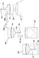
図13は、上述した吸蔵が完了した結晶スポンジ200を取り付けた試料ホルダ250を、アプリケータ300から取り外してゴニオメータ12の先端部のゴニオヘッド121に取り付ける(マウントする)ための試料ホルダ取付け機構600の構成の一例を示している。この試料ホルダ取付け機構600は、図にも示すように、互いに平行に配置され、かつ、互いに接近又は離反して移動して(図の矢印を参照)その間に試料ホルダ250の基台部251を保持/解放する一対の棒状の把持部611、611を含む試料ホルダ把持部610と、やはり、互いに平行に配置され、かつ、接近又は離反して移動可能で(図の矢印を参照)、その間にアプリケータ300を保持/解放する一対の棒状の部材621、621を含んだアプリケータ把持部620とを備えている。特に、前者の試料ホルダ把持部610は、図に矢印で示すように、更にそれ自体が回動すると共に、ゴニオメータ12のゴニオヘッド121に向かってその位置を移動することが可能に構成されている。なお、この試料ホルダ取付け機構600は、その機能から、単結晶X線回折装置9内のゴニオメータ12に近接した位置に配置されることが好ましいであろう。なお、試料ホルダ取付け機構600は、吸蔵装置500や吸蔵装置500と単結晶X線回折装置9との間など、単結晶X線回折装置9外に配置されてもよい。
図13は、上述した吸蔵が完了した結晶スポンジ200を取り付けた試料ホルダ250を、アプリケータ300から取り外してゴニオメータ12の先端部のゴニオヘッド121に取り付ける(マウントする)ための試料ホルダ取付け機構600の構成の一例を示している。この試料ホルダ取付け機構600は、図にも示すように、互いに平行に配置され、かつ、互いに接近又は離反して移動して(図の矢印を参照)その間に試料ホルダ250の基台部251を保持/解放する一対の棒状の把持部611、611を含む試料ホルダ把持部610と、やはり、互いに平行に配置され、かつ、接近又は離反して移動可能で(図の矢印を参照)、その間にアプリケータ300を保持/解放する一対の棒状の部材621、621を含んだアプリケータ把持部620とを備えている。特に、前者の試料ホルダ把持部610は、図に矢印で示すように、更にそれ自体が回動すると共に、ゴニオメータ12のゴニオヘッド121に向かってその位置を移動することが可能に構成されている。なお、この試料ホルダ取付け機構600は、その機能から、単結晶X線回折装置9内のゴニオメータ12に近接した位置に配置されることが好ましいであろう。なお、試料ホルダ取付け機構600は、吸蔵装置500や吸蔵装置500と単結晶X線回折装置9との間など、単結晶X線回折装置9外に配置されてもよい。
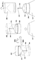
そして、試料ホルダ把持部610により試料ホルダ250の基台部251を把持し、同時に、アプリケータ把持部620によりアプリケータ300を把持した後、図14にも矢印で示すように、試料ホルダ把持部610は、把持した試料ホルダ250をアプリケータ300から取り外す方向へ、例えば、ここでは垂直方向に、より具体的には、ピン状の保持部252の延長方向に沿って移動する。このことによれば、試料ホルダ250は、そのピン状の保持部252の先端に取り付けられた結晶スポンジ200がアプリケータ300の一部に当接して破損・逸脱されることなく、安全に、アプリケータ300から取り外すことができる。その後、試料ホルダ把持部610は、それ自体が回転する(図の矢印を参照)ことにより試料ホルダ250の上下に逆転した状態で、試料ホルダ250をゴニオメータ12のゴニオヘッド121の先端に取り付ける。
あるいは、図15にも示すように、試料ホルダ把持部610(又はアプリケータ把持部620)により基台部251(又はアプリケータ300)の外周を把持した状態でゴニオヘッド121の位置へ移動し、回転して、アプリケータ300と一体となっている試料ホルダ250をゴニオヘッド121上に搭載してもよい。なお、この場合には、その後、アプリケータ把持部620によりアプリケータ300の外周を把持し、同時に、試料ホルダ把持部610によって基台部251を把持して静止した状態で、アプリケータ把持部620が垂直方向に移動することにより、上記と同様に、結晶スポンジ200を、アプリケータ300の一部に当接して破損・逸脱することなく、安全に、アプリケータ300から取り外してゴニオヘッド121の先端に取り付けることができる。なお、上記では試料ホルダ把持部610及びアプリケータ把持部620は、それぞれ、一対の平行移動が可能な棒状の部材から構成されるとして説明したが、これらの把持部は、試料ホルダ又はアプリケータを把持可能であればよく、その他、回転可能な部材によって構成されてもよく、或いは、所謂、ロボットアームのような把持手段(把持部)を採用して構成されてもよいことは、当業者であれば自明であろう。
このことによれば、ゴニオメータ12のゴニオヘッド121の先端に取り付けられる試料ホルダ250のピン状の保持部252の一部(先端)に取り付けられた結晶スポンジ200は、吸蔵が完了した後、試料ホルダ250をアプリケータ300から取り外す際においても、その他の部位に当接して破損・逸脱されることなく、安全かつ迅速に、X線管11からのX線ビームが集光されて照射される位置に正確に配置されることとなる。換言すれば、結晶スポンジ200に吸蔵された試料は、正確に、かつ、迅速かつ安全に、X線回折装置9内の所定の位置に配置され、その後、単結晶X線回折装置によって当該試料Sからの回折X線の強度が測定されて、その結晶構造等が解析されることとなる。
このように、本発明の試料ホルダ250やアプリケータ300、更には、試料ホルダ取付け機構600を利用することによれば、誰でも容易かつ安全に、極微量の試料を、試料ホルダ250に予め一体に取り付けられた極微小な寸法の結晶スポンジ200に吸蔵させると共に、その後、当該試料Sをゴニオメータ12に高精度で正確な位置に結晶スポンジが乾燥により破壊されない短時間で迅速に、かつ、安全に搭載することが可能となる。なお、その後、上述した単結晶X線回折装置9によって試料Sに所要の波長のX線を照射しながら対象材料によるX線の回折や散乱測定し、上述した単結晶X線構造解析装置を構成する測定用アプリケーションソフトにより構造解析を行って分子モデルの構築や最終レポートの作成等を行うことは現状と同様である。即ち、本実施例によれば、創薬や生命科学のみならず各種の材料研究の現場などにおいて、発見又は設計した新たな構造物の分子構造・集合構造(実空間)を、迅速、安全、かつ簡単に確認することが可能となる。
以上に詳述したように、本発明によれば、新たに提案された試料ホルダやアプリケータ、更には、その取付け機構を利用することにより、X線構造解析の専門知識がなくても、極微小で脆弱(fragile)な結晶スポンジを利用した単結晶X線構造解析を、従来必要とされた緻密で微細な作業を伴わずに、迅速、確実かつ容易に行うことが出来る、換言すれば、結晶スポンジを利用した単結晶X線構造解析を、歩留まり良くかつ効率的に行うことが可能な、汎用性に優れ、かつ、試料ホルダの搭載の自動化を含むユーザフレンドリな単結晶X線構造解析装置が提供される。
なお、以上には本発明の種々の実施例を説明したが、本発明は上記した実施例に限定されるものではなく様々な変形例が含まれる。例えば、上記した実施例は本発明を分かりやすく説明するためにシステム全体を詳細に説明したものであり、必ずしも説明した全ての構成を備えるものに限定されるものではない。また、ある実施例の構成の一部を他の実施例の構成に置き換えることが可能であり、またある実施例の構成に他の実施例の構成を加えることも可能であり、また、各実施例の構成の一部について、他の構成の追加・削除・置換をすることが可能であろう。
本発明は、物質構造の探索方法やそれに用いるX線構造解析装置等において広く利用可能である。
なお、本国際出願は、2018年11月22日に出願した日本国特許出願第2018-218756号に基づく優先権を主張するものであり、日本国特許出願第2018-218756号の全内容を本国際出願に援用する。
1…単結晶X線構造解析装置(全体)、9…単結晶X線回折装置、11…X線管、12…ゴニオメータ、22…X線検出器、102…測定装置、103…入力装置、104…画像表示装置、107…CPU、108…RAM、109…ROM、111…ハードディスク、116…分析用アプリケーションソフト、117…測定用アプリケーションソフト、121…ゴニオヘッド、250…試料ホルダ、200…結晶スポンジ、251…基台部、252…ピン状の保持部、253…細孔、254…試料導入管、300…アプリケータ、301…収納空間、302…開口部、600…試料ホルダ取付け機構、610…試料ホルダ把持部、620…アプリケータ把持部、611、621…把持部。
Claims (6)
- 物質の構造解析を行う単結晶X線構造解析装置に試料を保持する試料ホルダを取り付ける試料ホルダ取り付け装置であって、
着脱可能なアプリケータに装着されて提供された前記試料ホルダを、前記単結晶X線構造解析装置のゴニオメータに、前記試料ホルダを前記アプリケータから取り外した状態で取り付ける試料ホルダ取付け機構を備え、
前記試料ホルダは、内部に形成された複数の微細孔に前記試料を吸蔵可能な細孔性錯体結晶を含み、
前記細孔性錯体結晶は、前記試料ホルダが前記ゴニオメータに取り付けられた状態で、前記試料ホルダの前記X線照射部からのX線が照射される位置に固定されていることを特徴とする試料ホルダ取り付け装置。 - 請求項1に記載の試料ホルダ取り付け装置において、
前記試料ホルダ取付け機構は、
前記試料ホルダを把持する試料ホルダ把持部と、
前記アプリケータを把持するアプリケータ把持部と、を備え、
前記試料ホルダ把持部または前記アプリケータ把持部の少なくとも一方は、前記試料ホルダ把持部が前記試料ホルダを把持した状態で、前記アプリケータ把持部が把持している前記アプリケータから前記試料ホルダを取り外す方向に移動可能であることを特徴とする試料ホルダ取り付け装置。 - 請求項2に記載の試料ホルダ取り付け装置において、
前記試料ホルダ把持部は、前記試料ホルダの前記細孔性錯体結晶を取り付けたピン状の保持部の延長方向に移動可能であることを特徴とする試料ホルダ取り付け装置。 - 請求項2又は3に記載の試料ホルダ取り付け装置において、
前記試料ホルダ把持部は、前記試料ホルダを把持した状態で、回動可能であることを特徴とする試料ホルダ取り付け装置。 - 請求項2から4のいずれか一項に記載の試料ホルダ取り付け装置において、
前記試料ホルダ把持部は、前記試料ホルダを把持した状態で、前記ゴニオメータの試料ホルダ取付け位置に前記試料ホルダを取り付ける方向に移動可能であることを特徴とする試料ホルダ取り付け装置。 - 物質の構造解析を行う単結晶X線構造解析装置であって、
X線を発生するX線源と、
前記試料ホルダと、
前記試料ホルダを取り付けて回動するゴニオメータと、
前記ゴニオメータに取り付けられた前記試料ホルダに保持された前記試料に対して前記X線源からのX線を照射するX線照射部と、
前記試料により回折又は散乱されたX線を検出して測定するX線検出測定部と、
前記X線検出測定部に検出された回折又は散乱X線に基づいて前記試料の構造解析を行なう構造解析部と、
請求項1から請求項4のいずれか一項に記載の試料ホルダ取り付け装置と、を備えることを特徴とする単結晶X線構造解析装置。
Priority Applications (4)
| Application Number | Priority Date | Filing Date | Title |
|---|---|---|---|
| US17/295,857 US11835476B2 (en) | 2018-11-22 | 2019-11-21 | Single-crystal X-ray structure analysis apparatus and sample holder attaching device |
| CN201980088771.1A CN113287006A (zh) | 2018-11-22 | 2019-11-21 | 单晶x射线结构解析装置以及试样保持架安装装置 |
| JP2020557644A JP7237373B2 (ja) | 2018-11-22 | 2019-11-21 | 単結晶x線構造解析装置および試料ホルダ取り付け装置 |
| EP19886782.2A EP3885749A4 (en) | 2018-11-22 | 2019-11-21 | DEVICE FOR SINGLE CRYSTAL X-RAY STRUCTURE ANALYSIS AND SAMPLE HOLDER MOUNTING DEVICE |
Applications Claiming Priority (2)
| Application Number | Priority Date | Filing Date | Title |
|---|---|---|---|
| JP2018218756 | 2018-11-22 | ||
| JP2018-218756 | 2018-11-22 |
Publications (1)
| Publication Number | Publication Date |
|---|---|
| WO2020105720A1 true WO2020105720A1 (ja) | 2020-05-28 |
Family
ID=70774426
Family Applications (1)
| Application Number | Title | Priority Date | Filing Date |
|---|---|---|---|
| PCT/JP2019/045689 WO2020105720A1 (ja) | 2018-11-22 | 2019-11-21 | 単結晶x線構造解析装置および試料ホルダ取り付け装置 |
Country Status (5)
| Country | Link |
|---|---|
| US (1) | US11835476B2 (ja) |
| EP (1) | EP3885749A4 (ja) |
| JP (1) | JP7237373B2 (ja) |
| CN (1) | CN113287006A (ja) |
| WO (1) | WO2020105720A1 (ja) |
Cited By (1)
| Publication number | Priority date | Publication date | Assignee | Title |
|---|---|---|---|---|
| WO2022073621A1 (en) * | 2020-10-09 | 2022-04-14 | Merck Patent Gmbh | Flexible sample holder for crystalline sponge |
Citations (11)
| Publication number | Priority date | Publication date | Assignee | Title |
|---|---|---|---|---|
| JPH11304999A (ja) * | 1998-04-22 | 1999-11-05 | Rigaku Denki Kk | X線結晶構造解析装置のための試料保持用ゴニオメータ |
| JP2003139726A (ja) * | 2001-11-02 | 2003-05-14 | Toyota Motor Corp | 水素吸蔵合金の結晶構造解析方法 |
| US20050163280A1 (en) * | 2001-12-12 | 2005-07-28 | The Regents Of The University Of California | Integrated crystal mounting and alignment system for high-throughput biological crystallography |
| JP2007003394A (ja) | 2005-06-24 | 2007-01-11 | Rigaku Corp | 双晶解析装置 |
| US7660389B1 (en) * | 2007-08-17 | 2010-02-09 | Bruker Axs, Inc. | Sample alignment mechanism for X-ray diffraction instrumentation |
| JP2010203843A (ja) * | 2009-03-02 | 2010-09-16 | Rigaku Corp | X線及び熱分析装置 |
| JP2010286431A (ja) * | 2009-06-15 | 2010-12-24 | Rigaku Corp | 凍結結晶の処理装置及び処理方法 |
| US20110211674A1 (en) * | 2010-03-01 | 2011-09-01 | Cornell University | Goniometer base apparatus and method |
| WO2014038220A1 (ja) * | 2012-09-07 | 2014-03-13 | 独立行政法人 科学技術振興機構 | ゲスト化合物内包高分子金属錯体結晶、その製造方法、結晶構造解析用試料の作製方法、及び有機化合物の分子構造決定方法 |
| WO2016017770A1 (ja) | 2014-07-31 | 2016-02-04 | 国立研究開発法人 科学技術振興機構 | 回折データの解析方法、コンピュータプログラム及び記録媒体 |
| JP2018155680A (ja) * | 2017-03-21 | 2018-10-04 | 大学共同利用機関法人 高エネルギー加速器研究機構 | カセット装填装置 |
Family Cites Families (16)
| Publication number | Priority date | Publication date | Assignee | Title |
|---|---|---|---|---|
| JP3053502B2 (ja) | 1992-12-25 | 2000-06-19 | 日機装株式会社 | 粉末品分析用試料の精秤分取装置 |
| US20030068829A1 (en) | 2001-06-25 | 2003-04-10 | Symyx Technologies, Inc. | High throughput crystallographic screening of materials |
| JP3640383B2 (ja) | 2001-09-10 | 2005-04-20 | 独立行政法人理化学研究所 | サンプルの支持機構 |
| JP3697246B2 (ja) * | 2003-03-26 | 2005-09-21 | 株式会社リガク | X線回折装置 |
| JPWO2011115223A1 (ja) | 2010-03-18 | 2013-07-04 | 独立行政法人理化学研究所 | 生体高分子の結晶化条件探査方法及びそれに用いる装置 |
| JP2013156218A (ja) | 2012-01-31 | 2013-08-15 | Japan Synchrotron Radiation Research Institute | 微小試料用キャピラリー |
| JP6131595B2 (ja) | 2012-12-28 | 2017-05-24 | 株式会社ニコン | 測定方法 |
| WO2015132909A1 (ja) | 2014-03-05 | 2015-09-11 | 株式会社島津製作所 | 試料分析システム |
| EP3173774A1 (en) * | 2015-11-24 | 2017-05-31 | Paul Scherrer Institut | A system and a method for resolving a crystal structure of a crystal at atomic resolution by collecting x-ray diffraction images |
| DE102015224143B3 (de) * | 2015-12-03 | 2017-02-23 | Incoatec Gmbh | Verfahren zur Justage der Primärseite eines Röntgendiffraktometers und zugehöriges Röntgendiffraktometer |
| US10794844B2 (en) * | 2016-08-10 | 2020-10-06 | Proto Manufacturing, Ltd. | Mounting system and sample holder for X-ray diffraction apparatus |
| JP6606658B2 (ja) * | 2016-08-18 | 2019-11-20 | 株式会社リガク | X線回折装置 |
| JP6931214B2 (ja) * | 2017-01-19 | 2021-09-01 | 株式会社日立ハイテクサイエンス | 荷電粒子ビーム装置 |
| EP3591387B1 (en) | 2017-03-01 | 2023-09-27 | The University of Tokyo | Method for identifying molecular structure |
| JP2018169276A (ja) * | 2017-03-29 | 2018-11-01 | 株式会社島津製作所 | X線分析装置 |
| CN106932419A (zh) * | 2017-04-19 | 2017-07-07 | 南京大学 | X射线衍射仪毛细样品管支架及其使用方法 |
-
2019
- 2019-11-21 JP JP2020557644A patent/JP7237373B2/ja active Active
- 2019-11-21 EP EP19886782.2A patent/EP3885749A4/en active Pending
- 2019-11-21 US US17/295,857 patent/US11835476B2/en active Active
- 2019-11-21 CN CN201980088771.1A patent/CN113287006A/zh active Pending
- 2019-11-21 WO PCT/JP2019/045689 patent/WO2020105720A1/ja unknown
Patent Citations (11)
| Publication number | Priority date | Publication date | Assignee | Title |
|---|---|---|---|---|
| JPH11304999A (ja) * | 1998-04-22 | 1999-11-05 | Rigaku Denki Kk | X線結晶構造解析装置のための試料保持用ゴニオメータ |
| JP2003139726A (ja) * | 2001-11-02 | 2003-05-14 | Toyota Motor Corp | 水素吸蔵合金の結晶構造解析方法 |
| US20050163280A1 (en) * | 2001-12-12 | 2005-07-28 | The Regents Of The University Of California | Integrated crystal mounting and alignment system for high-throughput biological crystallography |
| JP2007003394A (ja) | 2005-06-24 | 2007-01-11 | Rigaku Corp | 双晶解析装置 |
| US7660389B1 (en) * | 2007-08-17 | 2010-02-09 | Bruker Axs, Inc. | Sample alignment mechanism for X-ray diffraction instrumentation |
| JP2010203843A (ja) * | 2009-03-02 | 2010-09-16 | Rigaku Corp | X線及び熱分析装置 |
| JP2010286431A (ja) * | 2009-06-15 | 2010-12-24 | Rigaku Corp | 凍結結晶の処理装置及び処理方法 |
| US20110211674A1 (en) * | 2010-03-01 | 2011-09-01 | Cornell University | Goniometer base apparatus and method |
| WO2014038220A1 (ja) * | 2012-09-07 | 2014-03-13 | 独立行政法人 科学技術振興機構 | ゲスト化合物内包高分子金属錯体結晶、その製造方法、結晶構造解析用試料の作製方法、及び有機化合物の分子構造決定方法 |
| WO2016017770A1 (ja) | 2014-07-31 | 2016-02-04 | 国立研究開発法人 科学技術振興機構 | 回折データの解析方法、コンピュータプログラム及び記録媒体 |
| JP2018155680A (ja) * | 2017-03-21 | 2018-10-04 | 大学共同利用機関法人 高エネルギー加速器研究機構 | カセット装填装置 |
Non-Patent Citations (9)
| Title |
|---|
| "Direct observation of hydrogen molecules adsorbed in a microporous coordination polymer", SPRING-8 INFORMATION, vol. 10, no. 1, January 2005 (2005-01-01), pages 24 - 29, XP001236796 * |
| "X-ray analysis on the nanogram to microgram scale using porous complexes", NATURE, vol. 495, 28 March 2013 (2013-03-28), pages 461 - 466, XP055400439 * |
| HOSHINO ET AL., THE UPDATED CRYSTALLINE SPONGE METHOD IUCRJ, vol. 3, 2016, pages 139 - 151 |
| KUROIWA, YOSHIHIRO: "Study on precise structural properties by powder crystal", SPRING-8 RIYOSHA JOHO - SPRING-8 INFORMATION, SPRING-8 RIYOSHA JOHO HENSHU IINKAI, KAMIGORI-CHO, JP, vol. 11, no. 4, 30 June 2006 (2006-06-30), JP, pages 202 - 219, XP009528339, ISSN: 1341-9668 * |
| MAKOTO FUJITA: "X-ray analysis on the nanogram to microgram scale using porous complexes", NATURE, vol. 495, 28 March 2013 (2013-03-28), pages 461 - 466, XP055400439, DOI: 10.1038/nature11990 |
| MASAHIKO HIRAKI: "RSJ2014AC1Q3-01: Development of sample exchange system for synchrotron radiation beamline", ANNUAL CONFERENCE OF THE ROBOTICS SOCIETY OF JAPAN , vol. 32, no. 1, 4 September 2014 (2014-09-04), JP, pages 1 - 2, XP009521330 * |
| See also references of EP3885749A4 |
| TAKATA MASAKI: "New Nano Science for one-dimensional arrays of dioxygen", SPRING-8 INFORMATION, vol. 8, no. 6, November 2003 (2003-11-01), pages 406 - 412, XP009521329, ISSN: 2187-4794 * |
| TAKATA, MASAKI; KATO, KEN-ICHI: "Precise structural studies for novel materials science by synchrotron radiation powder diffraction", JSAP INTERNATIONAL, vol. 74, no. 9, 31 August 2005 (2005-08-31), JP, pages 1201 - 1204, XP009528328, ISSN: 0369-8009, DOI: 10.11470/oubutsu.74.9_1201 * |
Cited By (1)
| Publication number | Priority date | Publication date | Assignee | Title |
|---|---|---|---|---|
| WO2022073621A1 (en) * | 2020-10-09 | 2022-04-14 | Merck Patent Gmbh | Flexible sample holder for crystalline sponge |
Also Published As
| Publication number | Publication date |
|---|---|
| EP3885749A4 (en) | 2022-10-12 |
| JPWO2020105720A1 (ja) | 2021-10-07 |
| US11835476B2 (en) | 2023-12-05 |
| US20220128491A1 (en) | 2022-04-28 |
| CN113287006A (zh) | 2021-08-20 |
| JP7237373B2 (ja) | 2023-03-13 |
| EP3885749A1 (en) | 2021-09-29 |
Similar Documents
| Publication | Publication Date | Title |
|---|---|---|
| JP2023164789A (ja) | 試料ホルダユニット | |
| JP7252654B2 (ja) | 単結晶x線構造解析試料の吸蔵装置及び吸蔵方法 | |
| JP7278526B2 (ja) | 単結晶x線構造解析システム | |
| JP7462164B2 (ja) | 単結晶x線構造解析装置用試料ホルダ、試料ホルダユニットおよび吸蔵方法 | |
| JP7278528B2 (ja) | 単結晶x線構造解析装置用試料ホルダユニット | |
| WO2020105720A1 (ja) | 単結晶x線構造解析装置および試料ホルダ取り付け装置 | |
| JP2023085421A (ja) | 単結晶x線構造解析装置とそのための方法 | |
| WO2020105716A1 (ja) | 単結晶x線構造解析装置と方法、及び、そのための試料ホルダ | |
| JP7278527B2 (ja) | 単結晶x線構造解析装置用試料ホルダユニット | |
| JP7237374B2 (ja) | 単結晶x線構造解析装置と方法、そのための試料ホルダ及びアプリケータ | |
| JP7300744B2 (ja) | 単結晶x線構造解析用試料の吸蔵装置と吸蔵方法 |
Legal Events
| Date | Code | Title | Description |
|---|---|---|---|
| 121 | Ep: the epo has been informed by wipo that ep was designated in this application |
Ref document number: 19886782 Country of ref document: EP Kind code of ref document: A1 |
|
| ENP | Entry into the national phase |
Ref document number: 2020557644 Country of ref document: JP Kind code of ref document: A |
|
| NENP | Non-entry into the national phase |
Ref country code: DE |
|
| ENP | Entry into the national phase |
Ref document number: 2019886782 Country of ref document: EP Effective date: 20210622 |