WO2020105691A1 - 光ファイバ用線引炉のシール構造、光ファイバの製造方法 - Google Patents
光ファイバ用線引炉のシール構造、光ファイバの製造方法Info
- Publication number
- WO2020105691A1 WO2020105691A1 PCT/JP2019/045518 JP2019045518W WO2020105691A1 WO 2020105691 A1 WO2020105691 A1 WO 2020105691A1 JP 2019045518 W JP2019045518 W JP 2019045518W WO 2020105691 A1 WO2020105691 A1 WO 2020105691A1
- Authority
- WO
- WIPO (PCT)
- Prior art keywords
- optical fiber
- blade members
- seal structure
- drawing furnace
- blade
- Prior art date
- Legal status (The legal status is an assumption and is not a legal conclusion. Google has not performed a legal analysis and makes no representation as to the accuracy of the status listed.)
- Ceased
Links
Images

Classifications
-
- C—CHEMISTRY; METALLURGY
- C03—GLASS; MINERAL OR SLAG WOOL
- C03B—MANUFACTURE, SHAPING, OR SUPPLEMENTARY PROCESSES
- C03B37/00—Manufacture or treatment of flakes, fibres, or filaments from softened glass, minerals, or slags
- C03B37/01—Manufacture of glass fibres or filaments
- C03B37/02—Manufacture of glass fibres or filaments by drawing or extruding, e.g. direct drawing of molten glass from nozzles; Cooling fins therefor
- C03B37/025—Manufacture of glass fibres or filaments by drawing or extruding, e.g. direct drawing of molten glass from nozzles; Cooling fins therefor from reheated softened tubes, rods, fibres or filaments, e.g. drawing fibres from preforms
- C03B37/029—Furnaces therefor
-
- C—CHEMISTRY; METALLURGY
- C03—GLASS; MINERAL OR SLAG WOOL
- C03B—MANUFACTURE, SHAPING, OR SUPPLEMENTARY PROCESSES
- C03B37/00—Manufacture or treatment of flakes, fibres, or filaments from softened glass, minerals, or slags
- C03B37/01—Manufacture of glass fibres or filaments
- C03B37/02—Manufacture of glass fibres or filaments by drawing or extruding, e.g. direct drawing of molten glass from nozzles; Cooling fins therefor
- C03B37/03—Drawing means, e.g. drawing drums ; Traction or tensioning devices
- C03B37/032—Drawing means, e.g. drawing drums ; Traction or tensioning devices for glass optical fibres
-
- C—CHEMISTRY; METALLURGY
- C03—GLASS; MINERAL OR SLAG WOOL
- C03B—MANUFACTURE, SHAPING, OR SUPPLEMENTARY PROCESSES
- C03B2205/00—Fibre drawing or extruding details
- C03B2205/60—Optical fibre draw furnaces
- C03B2205/70—Draw furnace insulation
-
- C—CHEMISTRY; METALLURGY
- C03—GLASS; MINERAL OR SLAG WOOL
- C03B—MANUFACTURE, SHAPING, OR SUPPLEMENTARY PROCESSES
- C03B2205/00—Fibre drawing or extruding details
- C03B2205/60—Optical fibre draw furnaces
- C03B2205/74—Means for moving at least a part of the draw furnace, e.g. by rotation or vertical or horizontal movement
-
- C—CHEMISTRY; METALLURGY
- C03—GLASS; MINERAL OR SLAG WOOL
- C03B—MANUFACTURE, SHAPING, OR SUPPLEMENTARY PROCESSES
- C03B2205/00—Fibre drawing or extruding details
- C03B2205/60—Optical fibre draw furnaces
- C03B2205/80—Means for sealing the preform entry or upper end of the furnace
Definitions
- the present disclosure relates to a seal structure for an optical fiber drawing furnace and a method for manufacturing an optical fiber.
- This application claims priority based on Japanese application No. 2018-218141 filed on November 21, 2018, and incorporates all the contents described in the Japanese application.
- Patent Document 1 discloses a technique of a sealing structure for closing a gap between an upper end opening of a drawing furnace and a glass base material.
- the seal structure of the drawing furnace for optical fibers of the present disclosure closes the gap between the upper end opening of the drawing furnace for optical fibers and the glass preform for optical fibers inserted into the core tube from the upper end opening.
- a sealing structure for an optical fiber drawing furnace comprising a plurality of blade members provided circumferentially so as to abut on a circumferential side surface of the glass preform for optical fibers, and provided around the plurality of blade members.
- a guide member for linearly sliding the plurality of blade members toward the circumferential side surface of the optical fiber glass preform, and the blade members in the radial direction of the optical fiber glass preform.
- a moving mechanism for moving the push-pull member.
- the center of gravity of the plurality of blade members is provided at a position rearward of the tip end surface of the guide member.
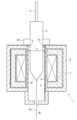
- FIG. 1 is a diagram illustrating an outline of an optical fiber drawing furnace according to an embodiment of the present disclosure.
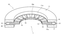
- FIG. 2 is a diagram showing an example of the seal structure.
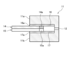
- FIG. 3 is a diagram for explaining the operation of the blade member in the seal structure.
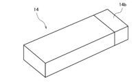
- FIG. 4 is a diagram illustrating a blade member according to the first embodiment.
- FIG. 5 is a diagram illustrating a blade member according to the second embodiment.
- the optical fiber is formed by inserting a glass base material for optical fiber whose main component is quartz (hereinafter referred to as glass base material) into the core tube through an upper end opening of a drawing furnace for optical fiber (hereinafter referred to as drawing furnace).
- glass base material glass base material
- drawing furnace drawing furnace for optical fiber
- the front end of the glass base material is heated and melted to be reduced in diameter, so that the glass base material is drawn from below the drawing furnace and manufactured. Since the temperature in the drawing furnace at this time is as high as about 2000 ° C., carbon parts having excellent heat resistance are often used for the parts in the drawing furnace.
- Patent Document 1 discloses a technique of a seal structure for closing a gap between the upper end opening of the drawing furnace and the glass base material.
- the blade member does not move to the intended position, not only outside air will enter the drawing furnace, but it may also affect the drawing operation.
- the blade member tilts downward due to its own weight at the advanced position, the blade member may not move due to friction with the surroundings, which may cause damage to the glass base material or the seal structure during insertion or removal of the glass base material. There is.
- a seal structure for an optical fiber drawing furnace includes (1) an upper end opening of the optical fiber drawing furnace and an optical fiber glass preform inserted into the core tube through the upper end opening.
- a push-pull action mechanism for moving the glass base material in the radial direction, and the center of gravity of the plurality of blade members is provided at a position rearward of the tip end surface of the guide member. Since the center of gravity of the blade member is provided at a position rearward of the tip end surface of the guide member, even when the blade member is in the advanced position, it is difficult to lean downward due to its own weight. Therefore, the blade member does not become difficult to move, and the closing operation of moving the blade member closer to the glass preform for optical fiber or the opening operation of moving the blade member away from the glass preform for optical fiber. As a result, it is possible not only to prevent outside air from entering the drawing furnace but also to prevent damage to the glass base material and the seal structure during insertion and removal of the glass base material.
- the center of gravity of the plurality of blade members is formed by forming a rear end side of the plurality of blade members with a material having a higher specific gravity than a front end side of the plurality of blade members, and thereby the front end surface of the guide member. It is provided at a position rearward of the above. If the material having a high specific gravity is used, the center of gravity of the blade member can be easily provided rearward.
- the center of gravity of the plurality of blade members is provided at a position rearward of the tip end surface of the guide member by installing a weight behind the center of the plurality of blade members. If the weight is installed, the center of gravity of the blade member can be easily provided rearward.
- the center of gravity of the plurality of blade members is formed so that the width of the rear end side of the plurality of blade members is made wider than that of the front end side of the plurality of blade members, so that Is also provided at the rear position. If the width of the rear end side of the blade member is wide, the center of gravity of the blade member can be easily provided rearward.
- the center of gravity of the plurality of blade members is formed to be thicker than the front end surface of the guide member by forming the thickness of the rear end side of the plurality of blade members to be thicker than the front end side of the blade members. It is provided at the rear position. If the thickness of the rear end side of the blade member is increased, the center of gravity of the blade member can be easily provided rearward.
- An optical fiber manufacturing method draws an optical fiber by using one of the seal structures of the optical fiber drawing furnace described above. Since the above-mentioned seal structure is used, damage to the glass base material and the seal structure during insertion and removal of the glass base material can be prevented.
- FIG. 1 is a diagram illustrating an outline of an optical fiber drawing furnace according to an embodiment of the present disclosure.
- the drawing furnace 1 includes a furnace casing 2, a core tube 3, a heating source (heater) 4, and a seal structure 10.
- the furnace housing 2 has an upper end opening 2a and a lower end opening 2b, and is made of, for example, stainless steel.
- the furnace core tube 3 is formed in a cylindrical shape in the central portion of the furnace casing 2 and communicates with, for example, the upper end opening 2a.
- the furnace core tube 3 is made of carbon, for example, and the glass base material 5 is inserted into the furnace core tube 3 in a state of being sealed by the seal structure 10 from the upper end opening 2a.
- a heater 4 is arranged in the furnace casing 2 so as to surround the core tube 3, and a heat insulating material 7 is housed so as to cover the outside of the heater 4.
- the heater 4 heats and melts the glass base material 5 inserted into the furnace core tube 3, and hangs down the melt-reduced optical fiber 5b from the lower end portion 5a thereof.
- the glass base material 5 can be moved in the drawing direction (downward direction) by a separately provided moving mechanism, and a support rod 6 for suspending and supporting the glass base material 5 is provided above the glass base material 5. Are connected.
- the drawing furnace 1 is provided with a supply mechanism (not shown) for supplying in-reactor gas such as an inert gas, so that an inert gas or the like for preventing oxidation and deterioration is provided in the core tube 3 and around the heater 4. It is possible to supply.
- in-reactor gas such as an inert gas
- FIG. 1 shows an example in which the upper end of the inner wall of the core tube 3 forms the upper end opening 2a as it is, the present invention is not limited to this.
- an upper end opening narrower than the inner diameter d of the core tube 3 may be provided on the upper side of the core tube 3.
- the gap to be sealed is between the narrow top opening and the glass base material 5. It becomes a gap that occurs.
- the cross-sectional shape of the glass base material 5 is basically generated aiming for a perfect circle, but a non-circle may be present in a part regardless of its accuracy, and it may be an elliptical shape or the like. May be.
- the cross section of the upper end opening 2a may be circular, but the accuracy does not matter.
- One embodiment of the present disclosure provides a seal structure 10 for closing a gap S between an upper end opening 2a of a drawing furnace 1 and an outer periphery of a glass base material 5 inserted into a furnace core tube 3 from the upper end opening 2a.
- the heater 4 heats the glass base material 5 in the drawing furnace while preventing the outside air outside the furnace from being trapped by the seal structure 10 provided in the upper end opening 2a.
- FIG. 2 is a diagram showing an example of the seal structure
- FIG. 3 is a diagram explaining the operation of the blade member in the seal structure.
- the seal structure 10 includes a plurality of blade members 14 and 15 having heat resistance, guide members 16 and 17 for accommodating the blade members 14 and 15 and linearly slidingly moving the blade members 14 and 15.
- the housing 11 that houses the blade members 14 and 15 and the guide members 16 and 17 and the blade members 14 and 15 have an action of pressing inward or pulling outward, for example, by utilizing the pressure difference of gas. And a push-pull action mechanism.
- the housing 11 is a disk-shaped member having concentric through holes, and an opening for inserting the blade members 14 and 15 is provided on the inner peripheral surface of the housing 11. ing.
- the inner peripheral surface of the housing 11 is located in the furnace internal space I communicating with the core tube 3 described in FIG. 1.
- the housing 11 is formed of, for example, stainless steel, and the blade members 14 and 15 and the guide members 16 and 17 are, for example, 400 ° C. or lower (300 ° C. or lower when carbon is used as the material of each member). ) May be included (for example, a water cooling system, not shown). If there is a cooling mechanism, it is possible to suppress deterioration of carbon or metal used for the blade members 14 and 15, the guide members 16 and 17, and the housing 11 due to radiant heat of the drawing furnace.
- the blade members 14 and 15 respectively extend radially with respect to the central axis of the housing 11 and are installed in the housing 11 in, for example, two upper and lower stages, and the blade members 14 are arranged substantially along the inner peripheral surface of the housing 11.
- a plurality of blade members 15 are provided at equal intervals, and a plurality of blade members 15 are also provided below the blade member 14 along the inner peripheral surface of the housing 11 at substantially equal intervals.
- the blade members 14 and 15 have, for example, a substantially rectangular parallelepiped shape whose cross-sectional shape in a plane perpendicular to the moving direction is a substantially rectangular shape, and are alternately arranged in two steps, and protrude from the housing 11 to protrude from the side surface of the glass base material. Abut.
- the material of the blade members 14 and 15 is preferably carbon, but other than carbon, for example, quartz glass, SiC-coated carbon, or the like can be adopted.
- the width and the number of blade members 14 and 15 described above may be appropriately selected depending on the outer diameter of the glass base material used, the outer diameter variation amount, the bending amount, and the like.
- the guide members 16 and 17 are formed, for example, so that the blade members 14 and 15 can be inserted therethrough.
- the guide member 16 is installed above the blade member 14, and the guide member 17 is installed below the blade member 15, respectively.
- the guide members 16 and 17 may be integrated with the housing 11.
- the material of the guide members 16 and 17 is also preferably carbon, but a metal such as boron nitride (BN), stainless steel, or molybdenum disulfide (MoS 2 ) can also be used.
- the housing 11 is provided with a supply / exhaust port 12 for supplying and exhausting gas to and from the internal pressure applying space 40, and the gas from the gas supply unit 51 is supplied via the supply / exhaust port 12. It can be stored in the pressure application space 40. Further, the gas accumulated in the pressure applying space 40 can be discharged (sucked out) from the gas discharge portion 52 via the supply / discharge port 12.
- the gas supply unit 51 and the gas discharge unit 52 are electrically connected to the controller 50.
- Front surfaces 11 a and 11 b are formed on the inner peripheral surface of the housing 11.
- the front surface 11a is provided at a position above the blade member 14 so as to be curved so as to surround the in-furnace space I described in FIG.
- the front surface 11b is provided below the blade member 15 and is also curved so as to surround the furnace internal space I.
- tip surfaces 16a and 17a are formed on the inner peripheral surfaces of the guide members 16 and 17, respectively.
- the tip surface 16a is provided so as to be curved so as to surround the furnace space I between the upper side of the blade member 14 and the front wall portion 11a, and the tip surface 17a is provided below the blade member 15 and the front wall portion 11b.
- the curved space is also provided so as to surround the furnace internal space I.
- the center of gravity of the blade members is always located rearward of the tip end surfaces 16a and 17a of the guide members 16 and 17 (positions near the outer peripheral surface of the housing 11) during the drawing operation. ).
- the method of providing the center of gravity of the blade member at a position rearward of the tip end surface of the guide member is not limited, for example, in the example shown in FIG. 4, the weight 14 a is installed behind the center of the blade member 14.
- the center of gravity of the blade member 15 is always the tip end of the guide member 17. It is maintained inside the housing 11 behind the surface 17a.
- the center of gravity of the blade members 14 and 15 is always provided at the position rearward of the tip surfaces 16a and 17a of the guide members 16 and 17, and the blade members 14 and 15 are at the advanced positions. Even if there is, it is difficult to lean downward due to its own weight.
- the blade member 14 does not have large friction with the upper guide member 16 and the lower blade member 15, and the blade member 15 does not have large friction with the upper blade member 14 and the lower guide member 17. Therefore, it is possible to reliably perform the closing operation of moving the blade members 14 and 15 toward the side surface of the glass base material and the opening operation of moving the blade members 14 and 15 away from the side surface of the glass base material.
- the center of gravity of the blade members 14 and 15 can be easily provided rearward. Then, according to the method for manufacturing an optical fiber using the above-mentioned seal structure, while suppressing the outside air from entering the drawing furnace, the glass base material and the seal structure are damaged when the glass base material is inserted or removed. Can be prevented.
- FIG. 5 is a diagram for explaining the blade member according to the second embodiment.
- a high specific gravity portion 14b made of, for example, tungsten having a higher specific gravity than the front end side is provided on the rear end side of the blade member 14, for example. If the blade member 14 is formed so as to increase the mass near the outer peripheral surface of the housing 11, the center of gravity of the blade member 14 can be easily provided rearward.
- the blade member 14 is described as an example in FIG. 5, if the blade member 15 is similarly formed, its center of gravity can be easily provided in the rear.
- the blade members 14 and 15 having a thick portion at the rear end may be used.
- the blade members 14 and 15 having a wide portion at the rear end may be used.
- the blade members 14 and 15 whose front ends are lightweight may be used.
- the blade members 14 and 15 are increased in thickness closer to the outer peripheral surface of the casing 11, or are increased in width closer to the outer peripheral surface of the casing 11, or are lighter toward the outer peripheral surface of the casing 11. With this configuration, the center of gravity of the blade members 14 and 15 can be easily provided rearward.
- SYMBOLS 1 Optical fiber drawing furnace, 2 ... Furnace housing, 2a ... Upper end opening, 2b ... Lower end opening, 3 ... Core tube, 4 ... Heater, 5 ... Optical fiber glass base material, 5a ... Lower end, 5b ... Optical fiber, 6 ... Support rod, 7 ... Heat insulating material, 10 ... Seal structure, 11 ... Housing, 11a, 11b ... Front, 12 ... Feed / eject port, 14, 15 ... Blade member, 14a, 15a ... Weight, 14b ... High specific gravity part, 16, 17 ... Guide member, 16a, 17a ... Tip surface, 40 ... Pressure applying space, 50 ... Controller, 51 ... Gas supply part, 52 ... Gas discharge part, S ... Upper end opening part and glass mother Gap between the outer circumference of the material, d ... Inner diameter of core tube.
Landscapes
- Engineering & Computer Science (AREA)
- Chemical & Material Sciences (AREA)
- Life Sciences & Earth Sciences (AREA)
- General Life Sciences & Earth Sciences (AREA)
- Geochemistry & Mineralogy (AREA)
- Manufacturing & Machinery (AREA)
- Materials Engineering (AREA)
- Organic Chemistry (AREA)
- Manufacture, Treatment Of Glass Fibers (AREA)
Abstract
光ファイバ用線引炉の上端開口部と上端開口部から炉心管に挿入される光ファイバ用ガラス母材との間の隙間を塞ぐための光ファイバ用線引炉のシール構造である。光ファイバ用ガラス母材の周方向側面に当接するように周状に設けた複数のブレード部材と、複数のブレード部材の周囲に設けられ、複数のブレード部材が光ファイバ用ガラス母材の周方向側面に向けて直線的にスライド移動するためのガイド部材と、ブレード部材を光ファイバ用ガラス母材の径方向に移動させる押引作用機構と、を有する。複数のブレード部材の重心は、ガイド部材の先端面よりも後方の位置に設けられる。
Description
本開示は、光ファイバ用線引炉のシール構造、光ファイバの製造方法に関する。
本出願は、2018年11月21日出願の日本出願第2018-218141号に基づく優先権を主張し、前記日本出願に記載された全ての記載内容を援用するものである。
本出願は、2018年11月21日出願の日本出願第2018-218141号に基づく優先権を主張し、前記日本出願に記載された全ての記載内容を援用するものである。
特許文献1には、線引炉の上端開口部とガラス母材との隙間を塞ぐためのシール構造の技術が開示されている。
本開示の光ファイバ用線引炉のシール構造は、光ファイバ用線引炉の上端開口部と該上端開口部から炉心管に挿入される光ファイバ用ガラス母材との間の隙間を塞ぐための光ファイバ用線引炉のシール構造であって、前記光ファイバ用ガラス母材の周方向側面に当接するように周状に設けた複数のブレード部材と、該複数のブレード部材の周囲に設けられ、該複数のブレード部材が前記光ファイバ用ガラス母材の前記周方向側面に向けて直線的にスライド移動するためのガイド部材と、前記ブレード部材を前記光ファイバ用ガラス母材の径方向に移動させる押引作用機構と、を有し、前記複数のブレード部材の重心は、前記ガイド部材の先端面よりも後方の位置に設けられる。
[本開示が解決しようとする課題]
光ファイバは、石英を主成分とする光ファイバ用ガラス母材(以下、ガラス母材という)を光ファイバ用線引炉(以下、線引炉という)の上端開口部から炉心管内に挿入し、ガラス母材の先端が加熱溶融して細径化されることにより、線引炉の下方から線引きされ、製造される。このときの線引炉内の温度は、約2000℃と非常に高温となるので、線引炉内の部品には、耐熱性に優れたカーボン製のものが使われることが多い。
光ファイバは、石英を主成分とする光ファイバ用ガラス母材(以下、ガラス母材という)を光ファイバ用線引炉(以下、線引炉という)の上端開口部から炉心管内に挿入し、ガラス母材の先端が加熱溶融して細径化されることにより、線引炉の下方から線引きされ、製造される。このときの線引炉内の温度は、約2000℃と非常に高温となるので、線引炉内の部品には、耐熱性に優れたカーボン製のものが使われることが多い。
カーボン部品の熱劣化を防ぐため、一般的には、不活性ガスで線引炉内を陽圧にし、外気(酸素)が線引炉内に入り込むことを防いでいるが、線引炉の上端開口部とガラス母材との隙間でうまく気密が取れていないと(シールされていないと)、外気を線引炉内に巻き込んでしまうことがある。これを防ぐため、例えば、特許文献1には、線引炉の上端開口部とガラス母材との隙間を塞ぐためのシール構造の技術が開示されている。
しかしながら、ブレード部材(シール部材)が予定していた位置まで移動しないと、線引炉内に外気が入り込むだけでなく、線引き動作に影響を与えることがある。また、前進した位置で、ブレード部材がその自重によって下方に傾くと、ブレード部材が周囲との摩擦によって動かなくなり、ガラス母材の挿入時や取出し時に、ガラス母材やシール構造の破損を招くおそれがある。
そこで、ブレード部材の閉動作や開動作を確実に行える光ファイバ用線引炉のシール構造、光ファイバの製造方法を提供することを目的とする。
[本開示の効果]
本開示によれば、線引炉内に外気が入り込むのを抑制するとともに、ガラス母材の挿入時や取出し時におけるガラス母材やシール構造の破損を防止することができる。
本開示によれば、線引炉内に外気が入り込むのを抑制するとともに、ガラス母材の挿入時や取出し時におけるガラス母材やシール構造の破損を防止することができる。
[本開示の実施形態の説明]
最初に本開示の実施形態の内容を列記して説明する。
本開示の一態様に係る光ファイバ用線引炉のシール構造は、(1)光ファイバ用線引炉の上端開口部と該上端開口部から炉心管に挿入される光ファイバ用ガラス母材との間の隙間を塞ぐための光ファイバ用線引炉のシール構造であって、前記光ファイバ用ガラス母材の周方向側面に当接するように周状に設けた複数のブレード部材と、該複数のブレード部材の周囲に設けられ、該複数のブレード部材が前記光ファイバ用ガラス母材の前記周方向側面に向けて直線的にスライド移動するためのガイド部材と、前記ブレード部材を前記光ファイバ用ガラス母材の径方向に移動させる押引作用機構と、を有し、前記複数のブレード部材の重心は、前記ガイド部材の先端面よりも後方の位置に設けられる。ブレード部材の重心がガイド部材の先端面よりも後方の位置に設けられているので、ブレード部材が前進した位置にあっても、自重で下方に傾き難くなる。よって、ブレード部材が動きづらくなるようなこともなく、ブレード部材を光ファイバ用ガラス母材に近づくように移動させる閉動作や、ブレード部材を光ファイバ用ガラス母材から離れるように移動させる開動作を確実に行えるので、線引炉内に外気が入り込むのを防ぐだけでなく、ガラス母材の挿入時や取出し時にガラス母材やシール構造が破損するのを防止することができる。
最初に本開示の実施形態の内容を列記して説明する。
本開示の一態様に係る光ファイバ用線引炉のシール構造は、(1)光ファイバ用線引炉の上端開口部と該上端開口部から炉心管に挿入される光ファイバ用ガラス母材との間の隙間を塞ぐための光ファイバ用線引炉のシール構造であって、前記光ファイバ用ガラス母材の周方向側面に当接するように周状に設けた複数のブレード部材と、該複数のブレード部材の周囲に設けられ、該複数のブレード部材が前記光ファイバ用ガラス母材の前記周方向側面に向けて直線的にスライド移動するためのガイド部材と、前記ブレード部材を前記光ファイバ用ガラス母材の径方向に移動させる押引作用機構と、を有し、前記複数のブレード部材の重心は、前記ガイド部材の先端面よりも後方の位置に設けられる。ブレード部材の重心がガイド部材の先端面よりも後方の位置に設けられているので、ブレード部材が前進した位置にあっても、自重で下方に傾き難くなる。よって、ブレード部材が動きづらくなるようなこともなく、ブレード部材を光ファイバ用ガラス母材に近づくように移動させる閉動作や、ブレード部材を光ファイバ用ガラス母材から離れるように移動させる開動作を確実に行えるので、線引炉内に外気が入り込むのを防ぐだけでなく、ガラス母材の挿入時や取出し時にガラス母材やシール構造が破損するのを防止することができる。
(2)前記複数のブレード部材の前記重心は、該複数のブレード部材の後端側を該複数のブレード部材の前端側よりも比重の高い材料で形成することにより、前記ガイド部材の前記先端面よりも前記後方の位置に設けられる。高比重の材料に変更すれば、ブレード部材の重心を後方に容易に設けることができる。
(3)前記複数のブレード部材の前記重心は、該複数のブレード部材の中心よりも後ろに錘を設置することにより、前記ガイド部材の前記先端面よりも前記後方の位置に設けられる。錘を設置すれば、ブレード部材の重心を後方に容易に設けることができる。
(4)前記複数のブレード部材の前記重心は、該複数のブレード部材の前記後端側の幅を該複数のブレード部材の前端側よりも広く形成することにより、前記ガイド部材の前記先端面よりも前記後方の位置に設けられる。ブレード部材の後端側の幅を広く形成すれば、ブレード部材の重心を後方に容易に設けることができる。
(5)前記複数のブレード部材の前記重心は、該複数のブレード部材の前記後端側の厚みを該ブレード部材の前端側よりも厚く形成することにより、前記ガイド部材の前記先端面よりも前記後方の位置に設けられる。ブレード部材の後端側の厚みを厚く形成すれば、ブレード部材の重心を後方に容易に設けることができる。
(6)本開示の一態様に係る光ファイバの製造方法は、上記いずれかの光ファイバ用線引炉のシール構造を用いて光ファイバを線引きする。上述のシール構造を用いているため、ガラス母材の挿入時や取出し時におけるガラス母材やシール構造の破損を防止できる。
(3)前記複数のブレード部材の前記重心は、該複数のブレード部材の中心よりも後ろに錘を設置することにより、前記ガイド部材の前記先端面よりも前記後方の位置に設けられる。錘を設置すれば、ブレード部材の重心を後方に容易に設けることができる。
(4)前記複数のブレード部材の前記重心は、該複数のブレード部材の前記後端側の幅を該複数のブレード部材の前端側よりも広く形成することにより、前記ガイド部材の前記先端面よりも前記後方の位置に設けられる。ブレード部材の後端側の幅を広く形成すれば、ブレード部材の重心を後方に容易に設けることができる。
(5)前記複数のブレード部材の前記重心は、該複数のブレード部材の前記後端側の厚みを該ブレード部材の前端側よりも厚く形成することにより、前記ガイド部材の前記先端面よりも前記後方の位置に設けられる。ブレード部材の後端側の厚みを厚く形成すれば、ブレード部材の重心を後方に容易に設けることができる。
(6)本開示の一態様に係る光ファイバの製造方法は、上記いずれかの光ファイバ用線引炉のシール構造を用いて光ファイバを線引きする。上述のシール構造を用いているため、ガラス母材の挿入時や取出し時におけるガラス母材やシール構造の破損を防止できる。
[本開示の実施形態の詳細]
以下、添付図面を参照しながら、本開示による光ファイバ用線引炉のシール構造、光ファイバの製造方法の好適な実施の形態について説明する。なお、以下ではヒータにより炉心管を加熱する抵抗炉を例に説明するが、コイルに高周波電源を印加し、炉心管を誘導加熱する誘導炉にも、本開示は適用可能である。また、ガラス母材の吊り下げ機構や、断熱材の構成なども、下記で説明するのは一例であり、これに限定されるものではない。
以下、添付図面を参照しながら、本開示による光ファイバ用線引炉のシール構造、光ファイバの製造方法の好適な実施の形態について説明する。なお、以下ではヒータにより炉心管を加熱する抵抗炉を例に説明するが、コイルに高周波電源を印加し、炉心管を誘導加熱する誘導炉にも、本開示は適用可能である。また、ガラス母材の吊り下げ機構や、断熱材の構成なども、下記で説明するのは一例であり、これに限定されるものではない。
図1は、本開示の一実施形態による光ファイバ用線引炉の概略を説明する図である。線引炉1は、炉筐体2と、炉心管3と、加熱源(ヒータ)4と、シール構造10とを備えている。炉筐体2は、上端開口部2aと下端開口部2bを有し、例えばステンレス鋼で形成されている。炉心管3は、炉筐体2の中央部に円筒状で形成され、例えば上端開口部2aと連通している。炉心管3は例えばカーボン製であり、この炉心管3内には、ガラス母材5が上端開口部2aからシール構造10でシールされた状態で挿入される。
炉筐体2内には、ヒータ4が炉心管3を囲むように配置され、断熱材7がヒータ4の外側を覆うように収納されている。ヒータ4は、炉心管3の内部に挿入されたガラス母材5を加熱溶融し、その下端部5aから溶融縮径された光ファイバ5bを垂下させる。ガラス母材5は、別途設けた移動機構により線引方向(下側方向)に移動可能であり、ガラス母材5の上側には、ガラス母材5を吊り下げて支持するための支持棒6が連結されている。また、線引炉1には不活性ガス等による炉内ガスの供給機構(図示省略)が設けられ、炉心管3内やヒータ4の周りに、酸化や劣化防止のための不活性ガス等を供給することが可能である。
なお、図1では、炉心管3の内壁の上端部がそのまま上端開口部2aを形成している例を挙げているが、これに限ったものではない。例えば、炉心管3の内径dよりさらに狭い上端開口部を炉心管3の上側に設けてもよく、この場合にシール対象となる隙間は、この狭い上端開口部とガラス母材5との間に生じる隙間となる。また、ガラス母材5の断面形状は、基本的に真円を目指して生成されたものとするが、その精度を問わず一部で非円が存在してもよく、また楕円形などであってもよい。また、上端開口部2aの断面は円形としておけばよいが、この精度は問わない。
本開示の一実施形態は、線引炉1の上端開口部2aと上端開口部2aから炉心管3に挿入されるガラス母材5の外周との間の隙間Sを塞ぐためのシール構造10を対象とするものであり、特に、上端開口部2aに設けたシール構造10によって炉外の外気を巻き込まないようにしながら、線引炉内のガラス母材5をヒータ4により加熱するものである。
図2はシール構造の一例を示す図であり、図3はシール構造におけるブレード部材の動作を説明する図である。
シール構造10は、耐熱性を持った複数のブレード部材14,15と、これらブレード部材14,15を収容し、ブレード部材14,15を直線的にスライド移動させるためのガイド部材16,17と、ブレード部材14,15やガイド部材16,17を収容する筐体11と、ブレード部材14,15を、例えば気体の圧力差を利用して内方に押し付けたり、外方に引っ張ったりする作用を有した押引作用機構と、を備えている。
シール構造10は、耐熱性を持った複数のブレード部材14,15と、これらブレード部材14,15を収容し、ブレード部材14,15を直線的にスライド移動させるためのガイド部材16,17と、ブレード部材14,15やガイド部材16,17を収容する筐体11と、ブレード部材14,15を、例えば気体の圧力差を利用して内方に押し付けたり、外方に引っ張ったりする作用を有した押引作用機構と、を備えている。
図2に示すように、筐体11は、同心の貫通孔を有した円盤状の部材であり、筐体11の内周面上に、ブレード部材14,15を挿通させるための開口が設けられている。筐体11の内周面は、図1で説明した炉心管3に連通する炉内空間Iに位置している。
筐体11は、例えばステンレス鋼で形成され、ブレード部材14,15やガイド部材16,17を例えば400℃以下(各部材の材質にカーボンを用いている場合には300℃以下にすることが好ましい)となるように冷却する機構(例えば水冷方式、図示省略)を有していてもよい。冷却する機構があれば、ブレード部材14,15やガイド部材16,17、筐体11に使用するカーボンや金属が、線引炉の輻射熱により劣化するのを抑制することができる。
筐体11は、例えばステンレス鋼で形成され、ブレード部材14,15やガイド部材16,17を例えば400℃以下(各部材の材質にカーボンを用いている場合には300℃以下にすることが好ましい)となるように冷却する機構(例えば水冷方式、図示省略)を有していてもよい。冷却する機構があれば、ブレード部材14,15やガイド部材16,17、筐体11に使用するカーボンや金属が、線引炉の輻射熱により劣化するのを抑制することができる。
ブレード部材14,15は、筐体11の中心軸に対してそれぞれ放射状に延びて、筐体11内に例えば上下2段で設置され、ブレード部材14は筐体11の内周面に沿って略等間隔で複数設けられ、ブレード部材15も、ブレード部材14の下側で、筐体11の内周面に沿って略等間隔で複数設けられている。ブレード部材14,15は、例えば、移動方向に垂直な面での断面形状が略長方形となる略直方体形状であり、上下2段で互い違いに配され、筐体11から突出してガラス母材の側面に当接する。
ブレード部材14,15の材料はカーボンであることが好ましいが、カーボンの他に、例えば、石英ガラス、SiCコートカーボンなどを採用することもできる。
なお、上述したブレード部材14,15の幅や枚数は、使用するガラス母材の外径や外径変動量や曲がり量などに応じて、適宜選べばよい。
なお、上述したブレード部材14,15の幅や枚数は、使用するガラス母材の外径や外径変動量や曲がり量などに応じて、適宜選べばよい。
ガイド部材16,17は、例えばブレード部材14,15を挿通可能に形成され、ガイド部材16はブレード部材14の上側に、ガイド部材17はブレード部材15の下側にそれぞれ設置される。なお、ガイド部材16,17は、筐体11と一体であってもよい。
ガイド部材16,17の材料もカーボンであることが好ましいが、窒化ボロン(BN)や、ステンレス、二硫化モリブテン(MoS2)などの金属を採用することもできる。
ガイド部材16,17の材料もカーボンであることが好ましいが、窒化ボロン(BN)や、ステンレス、二硫化モリブテン(MoS2)などの金属を採用することもできる。
図3により、押引作用機構として気体の圧力差を利用する例で、ブレード部材の動作について説明する。
図3に示すように、筐体11には、内部の圧力付与空間40にガスを供給、および排出する給排ポート12が設けられ、給排ポート12を介してガス供給部51からのガスを圧力付与空間40に溜めることができる。また、圧力付与空間40に溜まったガスは、給排ポート12を介してガス排出部52から排出する(吸い出す)ことも可能である。ガス供給部51やガス排出部52はコントローラ50に電気的に接続されている。
図3に示すように、筐体11には、内部の圧力付与空間40にガスを供給、および排出する給排ポート12が設けられ、給排ポート12を介してガス供給部51からのガスを圧力付与空間40に溜めることができる。また、圧力付与空間40に溜まったガスは、給排ポート12を介してガス排出部52から排出する(吸い出す)ことも可能である。ガス供給部51やガス排出部52はコントローラ50に電気的に接続されている。
筐体11の内周面上には、正面11a,11bが形成されている。正面11aは、ブレード部材14の上側の位置で、図2で説明した炉内空間Iを囲むように湾曲して設けられている。正面11bは、ブレード部材15の下側の位置で、同じく炉内空間Iを囲むように湾曲して設けられている。
また、ガイド部材16,17の内周面上には、先端面16a,17aが形成されている。先端面16aは、ブレード部材14の上側と正面壁部11aとの間で炉内空間Iを囲むように湾曲して設けられ、先端面17aは、ブレード部材15の下側と正面壁部11bとの間で、同じく炉内空間Iを囲むように湾曲して設けられている。
また、ガイド部材16,17の内周面上には、先端面16a,17aが形成されている。先端面16aは、ブレード部材14の上側と正面壁部11aとの間で炉内空間Iを囲むように湾曲して設けられ、先端面17aは、ブレード部材15の下側と正面壁部11bとの間で、同じく炉内空間Iを囲むように湾曲して設けられている。
ここで、本実施例のブレード部材14,15は、その重心が、線引き動作中は常に、ガイド部材16,17の先端面16a,17aよりも後方の位置(筐体11の外周面寄りの位置)に設けられるようにしている。
ブレード部材の重心をガイド部材の先端面より後方位置に設ける方法は限定されないが、例えば、図4に示す例では、ブレード部材14の中心よりも後ろに、錘14aが設置されている。これにより、ブレード部材14の先端面がガラス母材の側面から最も離れる場合(ブレード部材14が許容される移動範囲の最後退位置に達する場合)から、ガラス母材の側面に当接する場合(ほぼブレード部材14が許容される移動範囲の最前進位置に達した場合に相当)まで、ブレード部材14の重心は、常にガイド部材16の先端面16aよりも後方の、筐体11内に維持されることになる。
ブレード部材の重心をガイド部材の先端面より後方位置に設ける方法は限定されないが、例えば、図4に示す例では、ブレード部材14の中心よりも後ろに、錘14aが設置されている。これにより、ブレード部材14の先端面がガラス母材の側面から最も離れる場合(ブレード部材14が許容される移動範囲の最後退位置に達する場合)から、ガラス母材の側面に当接する場合(ほぼブレード部材14が許容される移動範囲の最前進位置に達した場合に相当)まで、ブレード部材14の重心は、常にガイド部材16の先端面16aよりも後方の、筐体11内に維持されることになる。
また、ブレード部材15の中心よりも後ろにも錘15aが設置され、ブレード部材15の先端面がガラス母材の側面に当接する場合にも、ブレード部材15の重心は、常にガイド部材17の先端面17aよりも後方の、筐体11内に維持される。
このように、本実施例では、ブレード部材14,15の重心が常にガイド部材16,17の先端面16a,17aよりも後方の位置に設けられており、ブレード部材14,15が前進した位置にあっても、自重で下方に傾き難くなる。
このように、本実施例では、ブレード部材14,15の重心が常にガイド部材16,17の先端面16a,17aよりも後方の位置に設けられており、ブレード部材14,15が前進した位置にあっても、自重で下方に傾き難くなる。
よって、ブレード部材14は、上方のガイド部材16や下方のブレード部材15との摩擦が大きくならず、また、ブレード部材15は、上方のブレード部材14や下方のガイド部材17との摩擦が大きくならないため、ブレード部材14,15をガラス母材の側面に近づくように移動させる閉動作や、ブレード部材14,15をガラス母材の側面から離れるように移動させる開動作を確実に行うことができる。
また、錘14a,15aを設置すれば、ブレード部材14,15の重心を後方に容易に設けることができる。
そして、上述のシール構造を用いた光ファイバの製造方法によれば、線引炉内に外気が入り込むのを抑制するとともに、ガラス母材の挿入時や取出し時におけるガラス母材やシール構造の破損を防止できる。
そして、上述のシール構造を用いた光ファイバの製造方法によれば、線引炉内に外気が入り込むのを抑制するとともに、ガラス母材の挿入時や取出し時におけるガラス母材やシール構造の破損を防止できる。
ところで、上記実施例では、ブレード部材14,15の重心を後方に設けるために、錘を設置する例を挙げて説明した。しかし、本開示はこの例に限定されるものでない。
図5は、実施例2によるブレード部材を説明する図であり、ブレード部材14の例えば後端側に、前端側よりも比重の重い、例えばタングステン製の高比重部14bが設けられている。ブレード部材14を、筐体11の外周面に近い方の質量を増やすように形成すれば、ブレード部材14の重心を後方に容易に設けることができる。
図5は、実施例2によるブレード部材を説明する図であり、ブレード部材14の例えば後端側に、前端側よりも比重の重い、例えばタングステン製の高比重部14bが設けられている。ブレード部材14を、筐体11の外周面に近い方の質量を増やすように形成すれば、ブレード部材14の重心を後方に容易に設けることができる。
なお、この図5ではブレード部材14の例で説明したが、ブレード部材15についても同様に形成すれば、その重心を後方に容易に設けることができる。
あるいは、その図示は省略するが、例えば後端に厚肉部を有したブレード部材14,15であってもよい。もしくは、例えば後端に幅広部を有したブレード部材14,15であってもよい。または、前端を軽量化したブレード部材14,15であってもよい。
ブレード部材14,15を、筐体11の外周面に近い方の厚みを増やす、もしくは、筐体11の外周面に近い方の幅を増やす、または、筐体11の外周面に遠い方を軽くするように形成すれば、ブレード部材14,15の重心を後方に容易に設けることができる。
あるいは、その図示は省略するが、例えば後端に厚肉部を有したブレード部材14,15であってもよい。もしくは、例えば後端に幅広部を有したブレード部材14,15であってもよい。または、前端を軽量化したブレード部材14,15であってもよい。
ブレード部材14,15を、筐体11の外周面に近い方の厚みを増やす、もしくは、筐体11の外周面に近い方の幅を増やす、または、筐体11の外周面に遠い方を軽くするように形成すれば、ブレード部材14,15の重心を後方に容易に設けることができる。
今回開示された実施の形態はすべての点で例示であって制限的なものではないと考えられるべきである。本開示の範囲は、上記した意味ではなく、請求の範囲によって示され、請求の範囲と均等の意味および範囲内でのすべての変更が含まれることが意図される。
1…光ファイバ用線引炉、2…炉筐体、2a…上端開口部、2b…下端開口部、3…炉心管、4…ヒータ、5…光ファイバ用ガラス母材、5a…下端部、5b…光ファイバ、6…支持棒、7…断熱材、10…シール構造、11…筐体、11a,11b…正面、12…給排ポート、14,15…ブレード部材、14a,15a…錘、14b…高比重部、16,17…ガイド部材、16a,17a…先端面、40…圧力付与空間、50…コントローラ、51…ガス供給部、52…ガス排出部、S…上端開口部とガラス母材の外周との間の隙間、d…炉心管の内径。
Claims (6)
- 光ファイバ用線引炉の上端開口部と該上端開口部から炉心管に挿入される光ファイバ用ガラス母材との間の隙間を塞ぐための光ファイバ用線引炉のシール構造であって、
前記光ファイバ用ガラス母材の周方向側面に当接するように周状に設けた複数のブレード部材と、
該複数のブレード部材の周囲に設けられ、該複数のブレード部材が前記光ファイバ用ガラス母材の前記周方向側面に向けて直線的にスライド移動するためのガイド部材と、
前記ブレード部材を前記光ファイバ用ガラス母材の径方向に移動させる押引作用機構と、を有し、
前記複数のブレード部材の重心は、前記ガイド部材の先端面よりも後方の位置に設けられる、光ファイバ用線引炉のシール構造。 - 前記複数のブレード部材の前記重心は、該複数のブレード部材の後端側を該複数のブレード部材の前端側よりも比重の高い材料で形成することにより、前記ガイド部材の前記先端面よりも前記後方の位置に設けられる、請求項1に記載の光ファイバ用線引炉のシール構造。
- 前記複数のブレード部材の前記重心は、該複数のブレード部材の中心よりも後ろに錘を設置することにより、前記ガイド部材の前記先端面よりも前記後方の位置に設けられる、請求項1または請求項2に記載の光ファイバ用線引炉のシール構造。
- 前記複数のブレード部材の前記重心は、該複数のブレード部材の前記後端側の幅を該複数のブレード部材の前端側よりも広く形成することにより、前記ガイド部材の前記先端面よりも前記後方の位置に設けられる、請求項1から請求項3のいずれか一項に記載の光ファイバ用線引炉のシール構造。
- 前記複数のブレード部材の前記重心は、該複数のブレード部材の前記後端側の厚みを該ブレード部材の前端側よりも厚く形成することにより、前記ガイド部材の前記先端面よりも前記後方の位置に設けられる、請求項1から請求項4のいずれか一項に記載の光ファイバ用線引炉のシール構造。
- 請求項1から請求項5のいずれか一項に記載の光ファイバ用線引炉のシール構造を用いて光ファイバを線引きする、光ファイバの製造方法。
Priority Applications (4)
| Application Number | Priority Date | Filing Date | Title |
|---|---|---|---|
| KR1020217015234A KR102730722B1 (ko) | 2018-11-21 | 2019-11-20 | 광 파이버용 신선 노의 시일 구조체 및 광 파이버의 제조 방법 |
| JP2020557605A JP7476799B2 (ja) | 2018-11-21 | 2019-11-20 | 光ファイバ用線引炉のシール構造、光ファイバの製造方法 |
| US17/295,630 US12503387B2 (en) | 2018-11-21 | 2019-11-20 | Seal structure of wire drawing furnace for optical fiber, and production method for optical fiber |
| CN201980076816.3A CN113165942B (zh) | 2018-11-21 | 2019-11-20 | 光纤用拉丝炉的密封构造、光纤的制造方法 |
Applications Claiming Priority (2)
| Application Number | Priority Date | Filing Date | Title |
|---|---|---|---|
| JP2018-218141 | 2018-11-21 | ||
| JP2018218141 | 2018-11-21 |
Publications (1)
| Publication Number | Publication Date |
|---|---|
| WO2020105691A1 true WO2020105691A1 (ja) | 2020-05-28 |
Family
ID=70773808
Family Applications (1)
| Application Number | Title | Priority Date | Filing Date |
|---|---|---|---|
| PCT/JP2019/045518 Ceased WO2020105691A1 (ja) | 2018-11-21 | 2019-11-20 | 光ファイバ用線引炉のシール構造、光ファイバの製造方法 |
Country Status (5)
| Country | Link |
|---|---|
| US (1) | US12503387B2 (ja) |
| JP (1) | JP7476799B2 (ja) |
| KR (1) | KR102730722B1 (ja) |
| CN (1) | CN113165942B (ja) |
| WO (1) | WO2020105691A1 (ja) |
Citations (4)
| Publication number | Priority date | Publication date | Assignee | Title |
|---|---|---|---|---|
| WO2014115849A1 (ja) * | 2013-01-24 | 2014-07-31 | 住友電気工業株式会社 | 光ファイバ用線引炉のシール構造、光ファイバの線引方法 |
| JP2014152083A (ja) * | 2013-02-12 | 2014-08-25 | Sumitomo Electric Ind Ltd | 光ファイバ用線引炉のシール構造、光ファイバの線引方法 |
| WO2018038156A1 (ja) * | 2016-08-23 | 2018-03-01 | 住友電気工業株式会社 | 光ファイバ用線引炉のシール構造、光ファイバの製造方法 |
| WO2018038154A1 (ja) * | 2016-08-23 | 2018-03-01 | 住友電気工業株式会社 | 光ファイバ用線引炉のシール構造、光ファイバの製造方法 |
Family Cites Families (13)
| Publication number | Priority date | Publication date | Assignee | Title |
|---|---|---|---|---|
| JPH0566620A (ja) * | 1991-09-06 | 1993-03-19 | Toshiba Corp | 画像形成装置 |
| JP2004131353A (ja) * | 2002-10-15 | 2004-04-30 | Mitsubishi Cable Ind Ltd | 光ファイバ母材の製造装置及び製造方法 |
| KR100970319B1 (ko) * | 2007-07-24 | 2010-07-15 | 신에쓰 가가꾸 고교 가부시끼가이샤 | 유리 모재 또는 광섬유 제조용 가열로 |
| JP5023016B2 (ja) | 2007-08-10 | 2012-09-12 | 信越化学工業株式会社 | 光ファイバ製造装置および線引き炉のシール方法 |
| JP5346567B2 (ja) | 2008-12-05 | 2013-11-20 | 株式会社フジクラ | 光ファイバ製造装置、光ファイバの製造方法 |
| JP2012001425A (ja) * | 2010-05-17 | 2012-01-05 | Sumitomo Electric Ind Ltd | 光ファイバ製造方法、光ファイバ及び光ファイバ母材 |
| JP5821514B2 (ja) | 2010-10-19 | 2015-11-24 | 住友電気工業株式会社 | 光ファイバ母材のシール構造 |
| JP5834561B2 (ja) * | 2011-07-14 | 2015-12-24 | 住友電気工業株式会社 | 光ファイバ母材用加熱炉のシール構造 |
| WO2012053394A1 (ja) | 2010-10-19 | 2012-04-26 | 住友電気工業株式会社 | 光ファイバ用線引炉のシール構造 |
| CN102838275B (zh) | 2012-08-28 | 2015-02-04 | 长飞光纤光缆股份有限公司 | 外径波动光纤预制棒的拉丝方法及装置 |
| JP5986540B2 (ja) * | 2013-06-24 | 2016-09-06 | 株式会社フジクラ | 光ファイバ素線の製造装置および製造方法 |
| CN203728719U (zh) * | 2014-03-14 | 2014-07-23 | 长飞光纤光缆股份有限公司 | 一种光纤拉丝炉密封装置 |
| JP6665695B2 (ja) * | 2016-06-03 | 2020-03-13 | 住友電気工業株式会社 | 光ファイバ用線引炉のシール構造、光ファイバの製造方法 |
-
2019
- 2019-11-20 WO PCT/JP2019/045518 patent/WO2020105691A1/ja not_active Ceased
- 2019-11-20 KR KR1020217015234A patent/KR102730722B1/ko active Active
- 2019-11-20 CN CN201980076816.3A patent/CN113165942B/zh active Active
- 2019-11-20 JP JP2020557605A patent/JP7476799B2/ja active Active
- 2019-11-20 US US17/295,630 patent/US12503387B2/en active Active
Patent Citations (4)
| Publication number | Priority date | Publication date | Assignee | Title |
|---|---|---|---|---|
| WO2014115849A1 (ja) * | 2013-01-24 | 2014-07-31 | 住友電気工業株式会社 | 光ファイバ用線引炉のシール構造、光ファイバの線引方法 |
| JP2014152083A (ja) * | 2013-02-12 | 2014-08-25 | Sumitomo Electric Ind Ltd | 光ファイバ用線引炉のシール構造、光ファイバの線引方法 |
| WO2018038156A1 (ja) * | 2016-08-23 | 2018-03-01 | 住友電気工業株式会社 | 光ファイバ用線引炉のシール構造、光ファイバの製造方法 |
| WO2018038154A1 (ja) * | 2016-08-23 | 2018-03-01 | 住友電気工業株式会社 | 光ファイバ用線引炉のシール構造、光ファイバの製造方法 |
Also Published As
| Publication number | Publication date |
|---|---|
| KR20210093905A (ko) | 2021-07-28 |
| KR102730722B1 (ko) | 2024-11-14 |
| CN113165942B (zh) | 2023-02-17 |
| US12503387B2 (en) | 2025-12-23 |
| US20220024800A1 (en) | 2022-01-27 |
| JP7476799B2 (ja) | 2024-05-01 |
| JPWO2020105691A1 (ja) | 2021-10-07 |
| CN113165942A (zh) | 2021-07-23 |
Similar Documents
| Publication | Publication Date | Title |
|---|---|---|
| RU2673094C2 (ru) | Способ вытяжки оптического волокна (варианты) | |
| CN106007361B (zh) | 光纤用拉丝炉的密封构造 | |
| US10487001B2 (en) | Seal structure of optical fiber drawing furnace, and method for drawing optical fiber | |
| CN109476522B (zh) | 玻璃管制造设备和方法 | |
| JP2015074600A (ja) | 光ファイバの製造方法 | |
| JP6048190B2 (ja) | 光ファイバ用線引炉のシール構造、光ファイバの線引方法 | |
| JP6024475B2 (ja) | 光ファイバ用線引炉のシール構造、光ファイバの線引方法 | |
| JP6476628B2 (ja) | 光ファイバの製造方法及び製造装置 | |
| WO2020105691A1 (ja) | 光ファイバ用線引炉のシール構造、光ファイバの製造方法 | |
| JP6973408B2 (ja) | 光ファイバ用線引炉のシール構造、光ファイバの製造方法 | |
| JP5821514B2 (ja) | 光ファイバ母材のシール構造 | |
| CN109689583B (zh) | 光纤拉丝方法及拉丝装置 | |
| JP6729171B2 (ja) | 光ファイバ用線引炉のシール構造、光ファイバの製造方法 | |
| JP6816670B2 (ja) | 光ファイバ用線引炉のシール構造、光ファイバの製造方法 | |
| JP6421569B2 (ja) | 光ファイバ製造方法及び光ファイバ製造装置 | |
| JP6665695B2 (ja) | 光ファイバ用線引炉のシール構造、光ファイバの製造方法 | |
| US20120051387A1 (en) | System and Method for Heating Material Samples | |
| JP5768484B2 (ja) | 耐熱ばね及びそれを用いた光ファイバ用線引炉のシール構造 | |
| CN116239295B (zh) | 用于高精度波导玻璃拉制的具有旋转基座的感应炉 | |
| JP2024092844A (ja) | 加熱炉 |
Legal Events
| Date | Code | Title | Description |
|---|---|---|---|
| 121 | Ep: the epo has been informed by wipo that ep was designated in this application |
Ref document number: 19887054 Country of ref document: EP Kind code of ref document: A1 |
|
| ENP | Entry into the national phase |
Ref document number: 2020557605 Country of ref document: JP Kind code of ref document: A |
|
| NENP | Non-entry into the national phase |
Ref country code: DE |
|
| 122 | Ep: pct application non-entry in european phase |
Ref document number: 19887054 Country of ref document: EP Kind code of ref document: A1 |