WO2020105652A1 - 開閉体開閉装置 - Google Patents
開閉体開閉装置Info
- Publication number
- WO2020105652A1 WO2020105652A1 PCT/JP2019/045337 JP2019045337W WO2020105652A1 WO 2020105652 A1 WO2020105652 A1 WO 2020105652A1 JP 2019045337 W JP2019045337 W JP 2019045337W WO 2020105652 A1 WO2020105652 A1 WO 2020105652A1
- Authority
- WO
- WIPO (PCT)
- Prior art keywords
- opening
- closing
- back door
- latch
- closing body
- Prior art date
- Legal status (The legal status is an assumption and is not a legal conclusion. Google has not performed a legal analysis and makes no representation as to the accuracy of the status listed.)
- Ceased
Links
Images


Classifications
-
- B—PERFORMING OPERATIONS; TRANSPORTING
- B60—VEHICLES IN GENERAL
- B60J—WINDOWS, WINDSCREENS, NON-FIXED ROOFS, DOORS, OR SIMILAR DEVICES FOR VEHICLES; REMOVABLE EXTERNAL PROTECTIVE COVERINGS SPECIALLY ADAPTED FOR VEHICLES
- B60J5/00—Doors
- B60J5/10—Doors arranged at the vehicle rear
-
- E—FIXED CONSTRUCTIONS
- E05—LOCKS; KEYS; WINDOW OR DOOR FITTINGS; SAFES
- E05B—LOCKS; ACCESSORIES THEREFOR; HANDCUFFS
- E05B85/00—Details of vehicle locks not provided for in groups E05B77/00 - E05B83/00
- E05B85/20—Bolts or detents
- E05B85/24—Bolts rotating about an axis
- E05B85/26—Cooperation between bolts and detents
-
- E—FIXED CONSTRUCTIONS
- E05—LOCKS; KEYS; WINDOW OR DOOR FITTINGS; SAFES
- E05B—LOCKS; ACCESSORIES THEREFOR; HANDCUFFS
- E05B81/00—Power-actuated vehicle locks
- E05B81/12—Power-actuated vehicle locks characterised by the function or purpose of the powered actuators
- E05B81/20—Power-actuated vehicle locks characterised by the function or purpose of the powered actuators for assisting final closing or for initiating opening
-
- E—FIXED CONSTRUCTIONS
- E05—LOCKS; KEYS; WINDOW OR DOOR FITTINGS; SAFES
- E05B—LOCKS; ACCESSORIES THEREFOR; HANDCUFFS
- E05B81/00—Power-actuated vehicle locks
- E05B81/54—Electrical circuits
- E05B81/64—Monitoring or sensing, e.g. by using switches or sensors
- E05B81/66—Monitoring or sensing, e.g. by using switches or sensors the bolt position, i.e. the latching status
-
- E—FIXED CONSTRUCTIONS
- E05—LOCKS; KEYS; WINDOW OR DOOR FITTINGS; SAFES
- E05B—LOCKS; ACCESSORIES THEREFOR; HANDCUFFS
- E05B81/00—Power-actuated vehicle locks
- E05B81/54—Electrical circuits
- E05B81/64—Monitoring or sensing, e.g. by using switches or sensors
- E05B81/70—Monitoring or sensing, e.g. by using switches or sensors the wing position
-
- E—FIXED CONSTRUCTIONS
- E05—LOCKS; KEYS; WINDOW OR DOOR FITTINGS; SAFES
- E05B—LOCKS; ACCESSORIES THEREFOR; HANDCUFFS
- E05B83/00—Vehicle locks specially adapted for particular types of wing or vehicle
- E05B83/16—Locks for luggage compartments, car boot lids or car bonnets
- E05B83/18—Locks for luggage compartments, car boot lids or car bonnets for car boot lids or rear luggage compartments
-
- E—FIXED CONSTRUCTIONS
- E05—LOCKS; KEYS; WINDOW OR DOOR FITTINGS; SAFES
- E05F—DEVICES FOR MOVING WINGS INTO OPEN OR CLOSED POSITION; CHECKS FOR WINGS; WING FITTINGS NOT OTHERWISE PROVIDED FOR, CONCERNED WITH THE FUNCTIONING OF THE WING
- E05F15/00—Power-operated mechanisms for wings
- E05F15/60—Power-operated mechanisms for wings using electrical actuators
- E05F15/603—Power-operated mechanisms for wings using electrical actuators using rotary electromotors
- E05F15/611—Power-operated mechanisms for wings using electrical actuators using rotary electromotors for swinging wings
-
- E—FIXED CONSTRUCTIONS
- E05—LOCKS; KEYS; WINDOW OR DOOR FITTINGS; SAFES
- E05F—DEVICES FOR MOVING WINGS INTO OPEN OR CLOSED POSITION; CHECKS FOR WINGS; WING FITTINGS NOT OTHERWISE PROVIDED FOR, CONCERNED WITH THE FUNCTIONING OF THE WING
- E05F15/00—Power-operated mechanisms for wings
- E05F15/60—Power-operated mechanisms for wings using electrical actuators
- E05F15/603—Power-operated mechanisms for wings using electrical actuators using rotary electromotors
- E05F15/611—Power-operated mechanisms for wings using electrical actuators using rotary electromotors for swinging wings
- E05F15/616—Power-operated mechanisms for wings using electrical actuators using rotary electromotors for swinging wings operated by push-pull mechanisms
- E05F15/622—Power-operated mechanisms for wings using electrical actuators using rotary electromotors for swinging wings operated by push-pull mechanisms using screw-and-nut mechanisms
-
- E—FIXED CONSTRUCTIONS
- E05—LOCKS; KEYS; WINDOW OR DOOR FITTINGS; SAFES
- E05F—DEVICES FOR MOVING WINGS INTO OPEN OR CLOSED POSITION; CHECKS FOR WINGS; WING FITTINGS NOT OTHERWISE PROVIDED FOR, CONCERNED WITH THE FUNCTIONING OF THE WING
- E05F15/00—Power-operated mechanisms for wings
- E05F15/60—Power-operated mechanisms for wings using electrical actuators
- E05F15/603—Power-operated mechanisms for wings using electrical actuators using rotary electromotors
- E05F15/632—Power-operated mechanisms for wings using electrical actuators using rotary electromotors for horizontally-sliding wings
- E05F15/655—Power-operated mechanisms for wings using electrical actuators using rotary electromotors for horizontally-sliding wings specially adapted for vehicle wings
- E05F15/659—Control circuits therefor
-
- E—FIXED CONSTRUCTIONS
- E05—LOCKS; KEYS; WINDOW OR DOOR FITTINGS; SAFES
- E05Y—INDEXING SCHEME ASSOCIATED WITH SUBCLASSES E05D AND E05F, RELATING TO CONSTRUCTION ELEMENTS, ELECTRIC CONTROL, POWER SUPPLY, POWER SIGNAL OR TRANSMISSION, USER INTERFACES, MOUNTING OR COUPLING, DETAILS, ACCESSORIES, AUXILIARY OPERATIONS NOT OTHERWISE PROVIDED FOR, APPLICATION THEREOF
- E05Y2400/00—Electronic control; Electrical power; Power supply; Power or signal transmission; User interfaces
- E05Y2400/10—Electronic control
- E05Y2400/32—Position control, detection or monitoring
- E05Y2400/334—Position control, detection or monitoring by using pulse generators
-
- E—FIXED CONSTRUCTIONS
- E05—LOCKS; KEYS; WINDOW OR DOOR FITTINGS; SAFES
- E05Y—INDEXING SCHEME ASSOCIATED WITH SUBCLASSES E05D AND E05F, RELATING TO CONSTRUCTION ELEMENTS, ELECTRIC CONTROL, POWER SUPPLY, POWER SIGNAL OR TRANSMISSION, USER INTERFACES, MOUNTING OR COUPLING, DETAILS, ACCESSORIES, AUXILIARY OPERATIONS NOT OTHERWISE PROVIDED FOR, APPLICATION THEREOF
- E05Y2400/00—Electronic control; Electrical power; Power supply; Power or signal transmission; User interfaces
- E05Y2400/10—Electronic control
- E05Y2400/40—Control units therefor
-
- E—FIXED CONSTRUCTIONS
- E05—LOCKS; KEYS; WINDOW OR DOOR FITTINGS; SAFES
- E05Y—INDEXING SCHEME ASSOCIATED WITH SUBCLASSES E05D AND E05F, RELATING TO CONSTRUCTION ELEMENTS, ELECTRIC CONTROL, POWER SUPPLY, POWER SIGNAL OR TRANSMISSION, USER INTERFACES, MOUNTING OR COUPLING, DETAILS, ACCESSORIES, AUXILIARY OPERATIONS NOT OTHERWISE PROVIDED FOR, APPLICATION THEREOF
- E05Y2900/00—Application of doors, windows, wings or fittings thereof
- E05Y2900/50—Application of doors, windows, wings or fittings thereof for vehicles
- E05Y2900/53—Type of wing
- E05Y2900/546—Tailboards, tailgates or sideboards opening upwards
Definitions
- the present invention relates to an opening / closing device opening / closing device.
- the opening / closing body that opens or closes the opening of the base body, when driving by the driving unit, open / close in order to stop driving at an appropriate position or drive at a driving speed according to the position. It is necessary to detect the current position of the body.
- Such an opening / closing body can know the current position by detecting a pulse signal according to the driving of the driving unit, for example, but it is known that such a detection signal causes a transmission error due to aging or the like.
- the integrated value of the pulse signal is reset when the switch member of the closer mechanism is activated, and reset when the opening / closing member is located at the fully closed position.
- a switchgear that does not do so has been proposed (for example, Patent Document 1).
- the opening / closing body is movable such as on a slope, and the integrated pulse signals are reset by the operation of the switch member of the closing mechanism by the opening / closing body, it moves before the opening / closing body is locked and the closing mechanism is closed. Even if the integrated value of the pulse signal is reset at a position different from the lock position of the opening / closing body due to, it is difficult to distinguish from the original reset position. If the integrated value of the pulse signal is reset at a position different from the original reset position and the zero position of the opening / closing body is set, a problem will occur in the operation of the opening / closing body due to the difference from the original zero position. If the movement amount of the opening / closing body is narrowed so that such a problem of the operation of the opening / closing body does not occur, the convenience is reduced.
- An object of the present invention is to provide an opening / closing body opening / closing device capable of setting the zero position by locking the closing mechanism even if the opening / closing body is set to a zero position at an inappropriate position.
- an opening / closing body opening / closing device of the present invention includes an opening / closing body that opens and closes with respect to an opening of a base body, a closing mechanism that locks the opening and closing body in a closed state, a control unit that controls driving of the closing mechanism, and the opening and closing body.
- An opening / closing body opening / closing device including a position detection unit for detecting a body position, wherein the closing mechanism is provided on one of the base body and the opening / closing body, and on the other side.
- the open state of the engaging part is a state in which the engaged part is movable to a position in which the engaged part can engage with the engaging part, and the closed state of the engaging part.
- the control unit when the transition of the engaging portion of the closing mechanism to the closed state or the open state, Zero position setting is performed to set the position information indicating the position of the opening / closing body to the zero position.
- the opening / closing body opening / closing device can be manually operated when the opening / closing body is closed, but the control section causes an interaction between the engaging section and the engaged section.
- the close mechanism side drive unit can be caused to perform the close drive in which the engagement unit transits to the closed state.
- the zero position can be set by locking the closing mechanism.
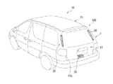
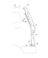
- FIG. 1 It is a perspective view showing a vehicle provided with an opening-and-closing body opening and closing device. It is a side view showing a state where a back door of a vehicle is in a closed posture. It is a side view showing a state where a back door of a vehicle is in an open posture. It is a block diagram showing an opening-and-closing body opening and closing device. (A) is a figure showing a state where a striker and a latch have separated, and (b) is a figure showing a state where a striker is in contact with a cam member of a latch.
- FIG. 1 is a diagram showing a state in which the striker and the cam member of the latch are in a engageable positional relationship, and (b) shows a state in which the latch has transitioned to the closed state and the striker has reached the locked position.
- FIG. It is a figure which shows the contact start position of a back door which is a closed position, an engagement position, and a closed position. It is a figure which shows the flow of the close control by a control part.
- the opening / closing body opening / closing device 1 shown in FIGS. 1 to 4 is an embodiment of the opening / closing body opening / closing device according to the present invention, and is provided in the vehicle 10.
- the opening / closing body opening / closing device 1 is a device that controls an opening / closing operation of a back door (opening / closing body) 12 that opens and closes an opening 11 a of a vehicle body 11 of a vehicle 10.
- the vehicle body 11 is an example of a base body
- the back door 12 is an example of an opening / closing body.
- the opening / closing body opening / closing device 1 includes a back door 12, an opening / closing body driving unit 20, a closing mechanism 30, a position detection unit 40, and a control unit 50.
- the control unit 50 controls driving of the opening / closing body driving unit 20 and the closing mechanism 30.
- the opening 11a is located at the rear of the vehicle body 11.
- the back door 12 is provided at the rear part of the vehicle body 11 and is configured to open and close the opening 11a.
- the back door 12 has an upper end rotatably supported by the vehicle body 11 via a hinge. The back door 12 can move between the closed position (see FIG. 2) and the open position (see FIG. 3) by moving around the upper end portion.
- the opening / closing body drive unit 20 moves the opening / closing body 12 in the opening direction and the closing direction with respect to the opening 11 a of the opening member 100.
- two opening / closing body driving units 20 are provided, one on each of the left and right ends of the opening / closing body 12 and on each of the left and right edges of the opening 11a.
- the opening / closing body 12 is moved by being driven by each of the opening / closing body driving units 20, so that the opening / closing body 12 moves relative to the opening member 100 and transitions to an open state or a closed state.
- the two opening / closing body drive units 20 move the opening / closing body 12 in a direction that opens the opening / closing body 12 (opening direction) and a direction that closes the opening / closing body 12 (closing direction). If it is possible to transition the open / close body 12 between the open state and the closed state, each of the open / close body drive units 20 may drive the open / close body 12 in the same direction and with the same drive amount. Further, as long as each of the two opening / closing body drive units 20 can move the opening / closing body 12 in the opening direction and the closing direction, the opening / closing body 12 can be driven with different driving amounts even when driving in different directions. You can In the present embodiment, each opening / closing body drive unit 20 is provided so as to perform the same drive in synchronization.
- the opening / closing body drive unit 20 has one end connected to the opening member 100 and the other end connected to the opening / closing body 12.
- the opening / closing body 12 is provided so as to be movable relative to the opening member 100, and in the present embodiment, is provided in the opening member 100 so as to be rotatable around a hinge.
- the opening / closing body 12 is attached to the opening / closing body 12 such that the opening / closing body 12 can pivot with respect to the opening member 100.
- the opening / closing body 12 is transited to the open state or the closed state.
- each opening / closing body drive unit 20 has a rod-shaped appearance that expands and contracts, is arranged on one end side of the opening / closing body drive unit 20, and is connected to the opening member 100 side, and a drive main body section, It has an advancing / retreating part which is disposed on the other end side of the opening / closing body drive part 20 and is connected to the opening / closing body 12 side. The advancing / retreating part is attached so as to be retractable from the other end side of the drive body part.
- Each opening / closing body drive unit 20 is connected to the opening member 100 and the opening / closing body 12 via a rotatable joint structure such as a ball joint.
- the opening / closing body drive unit 20 moves the advancing / retreating portion forward / backward with respect to the drive body in the longitudinal direction of the opening / closing body drive unit 20 to completely close the opening / closing body 12, that is, a position at which the opening 11a is completely closed. It can be moved to a fully open position, that is, a position where the opening 11 is opened to the maximum extent.
- Each opening / closing body drive unit 20 moves the opening / closing body 12 in the opening direction or the closing direction by converting the rotational movement of a motor or the like into a linear expansion / contraction movement.
- the opening / closing body drive section 20 was provided in total at two pieces on each of the left and right ends of the rear part of the vehicle. However, as long as the opening / closing body 12 can be opened / closed, its structure, drive system, shape and The arrangement position is not particularly limited.
- the open / close body drive unit 20 can employ a known drive unit that can drive the open / close body 12.
- the opening / closing body drive unit 20 includes a main body cylinder portion 201, a slide cylinder portion 202, an opening / closing motor 203 (not shown), a spindle (not shown), a spindle nut (not shown), and a biasing member (not shown). ) Etc.
- the main body cylinder portion 201, the opening / closing motor 203, the spindle, the urging member and the like correspond to the drive main body portion
- the slide cylinder portion 202 and the spindle nut correspond to the advancing and retracting portion.
- the main body tubular portion 201 has one end side rotatably fixed to the opening member 100 and the other end side open. Inside the main body tubular part 201, a slide tubular part 202 is arranged so as to be slidable in the longitudinal direction so that it slides in and out from the other end side of the main body tubular part 201.
- the opening / closing motor 203 is driven to move the advancing / retreating part in the longitudinal direction with respect to the drive main body, thereby expanding / contracting the opening / closing body drive part 20.
- the opening / closing motor 203 is a DC motor or an AC motor.
- the opening / closing motor 203 is connected to the control unit 50, and the control unit 50 controls both forward rotation and reverse rotation driving.
- the slide cylinder portion 202 is urged by the urging member from one end side of the main body cylinder portion 201 toward the other end side.
- a spindle nut in which a spindle that rotates around an axis by the rotation of the opening / closing motor 203 is screwed is provided.
- the opening / closing body drive unit 20 is configured so that the main body cylinder portion 201 and the slide cylinder portion 202 do not rotate with each other due to the rotation of the spindle.
- the open / close motor 203 rotates in one of the forward and reverse directions
- the spindle rotates in one direction around the forward and reverse axes
- the spindle nut screwed to the spindle moves along the longitudinal direction of the spindle.
- the slide cylinder portion 202 having the spindle nut moves back and forth, that is, slides in the longitudinal direction.
- the opening / closing body drive unit 20 moves so as to expand and contract, and the opening / closing body 12 is opened / closed in accordance with the length of the slide cylinder portion 202 extending from the main body cylinder portion 201.
- the closing mechanism 30 is a mechanism for locking the back door 12 in the closed position on the vehicle body 11.
- the closing mechanism 30 is provided on the vehicle body 11 and the back door 12.
- the closing mechanism 30 has a latch 31, a striker 32, an interaction detecting section 33, and a closing mechanism side driving section 34.
- the latch 31 is an example of an engaging portion
- the striker 32 is an example of an engaged portion.
- the latch 31 is attached to the lower end of the back door 12.
- the striker 32 is attached to the rear portion of the vehicle body 11.
- the striker 32 is arranged so that it can be positioned so as to be engageable with the latch 31 when the back door 12 is in the closed position.
- the latch 31 is configured to be engageable with the striker 32.
- the latch 31 is configured to be able to transition between an open state and a closed state.
- the open state of the latch 31 is a state in which the striker 32 can move from a position where it cannot engage with the latch 31 to a position where it can engage with the latch 31.
- the closed state of the latch 31 is a state in which the striker 32 is closed by the latch 31. In the closed state of the latch 31, the movement of the striker 32 is hindered by the latch 31 like a full latch, for example.
- the open position of the latch 31 is sometimes referred to as a full open position, and can include a neutral position as long as it can move to an engageable position.
- the closed position of the latch 31 is sometimes referred to as the fully closed position and may include the half-latch position if the striker 32 is locked by the latch 31.
- the closed position of the latch 31 is also the locked position of the striker 32.
- the closing mechanism side drive unit 34 is configured by a drive member for driving the latch 31, and the transition between the open state and the closed state of the latch 31 should be performed by the drive of the closing mechanism side drive unit 34. Is possible.
- the closing mechanism side drive unit 34 is composed of, for example, a drive motor.
- the latch 31 reaches the position at which the striker 32 can be engaged.
- the striker 32 is locked by mechanically driving the latch 31 by pushing the back door 12 or driving the closing mechanism side driving unit 34 by the control unit 50.
- the opening at the rear of the vehicle is in a state where the back door 12 is completely closed.
- a groove 317 capable of receiving the striker 32 is provided at the lower end of the back door 12.
- the striker 32 enters the groove 317 when the back door 12 as an opening / closing body moves to the closing side and reaches the closing position.
- the latch 31 is arranged at a position movable in the groove 317 of the back door 12.
- the latch 31 has a cam member 314 that is rotatably supported by the back door 12, and a lock member 315 that holds the cam member 314 at a predetermined rotation position.
- the cam member 314 is formed of a substantially disc-shaped member.
- a recess 316 capable of receiving the striker 32 is formed on a part of the outer peripheral surface of the cam member 314.
- the cam member 314 and the striker 32 are in a positional relationship capable of engaging with each other. That is, in the state shown in FIG. 6A, the rotational position of the cam member 314 is the position at which the striker 32 can be engaged. Further, in the state shown in FIG. 6A, the back door 12 is in a so-called half-door state, not in the locked and closed state.
- the cam member 314 When the cam member 314 is rotated to the engageable position, the cam member 314 is rotationally driven by the closing mechanism side drive unit 34.
- a cam switch that transmits an ON signal when the cam member 314 is rotated to the engageable position is provided in the cam member, and when the ON signal is input from the cam switch, the closing mechanism side drive unit 34 is driven. Can be configured to.
- the striker 32 can be guided to the locked position by rotationally driving the cam member 314 from the engageable position shown in FIG. 6A in the counterclockwise direction in the drawing to shift the latch 31 to the closed state. .. As shown in FIG. 6B, when the transition of the latch 31 to the closed state is completed, the striker 32 reaches the lock position and the back door 12 is completely closed.
- the cam member 314 has a cam surface 318 arranged at a position different from the recess 316 on the outer peripheral surface of the cam member 314.
- the cam surface 318 projects radially outward from other portions of the outer peripheral surface of the cam member 314.
- the cam member 314 has an outer peripheral surface 314a between the cam surface 318 and the recess 316 in the circumferential direction.
- the lock member 315 has a contact portion 319 that contacts the outer peripheral surface of the cam member 314.
- the lock member 315 is biased in a direction in which the contact portion 319 contacts the outer peripheral surface of the cam member 314.
- the contact portion 319 is rotated by the striker 32 from the time when the cam member 314 is in the posture shown in FIG. 5A and the latch 31 is in the open state, so that the contact portion 319 shown in FIG. It contacts the cam surface 318 until it reaches the mating position.
- the contact portion of the contact portion 319 with respect to the cam member 314 transitions from the cam surface 318 to the outer peripheral surface 314a.
- the latch 31 is transited to the closed state. It is possible to guide the striker 32 to the lock position and bring the back door 12 into a completely closed state.
- the back door 12 is provided with the latch 31 and the vehicle body 11 is provided with the striker 32.
- the vehicle body 11 may be provided with the latch 31 and the back door 12 may be provided with the striker 32. it can.
- a known closing mechanism of a latch and a striker may be adopted.
- the interaction detection unit 33 detects that the latch 31 and the striker 32 have interacted with each other.
- the latch 31 and the striker 32 interact with each other means that one side or the other side or both sides work so as to establish the relationship between the latch 31 and the striker 32.
- the interaction between the latch 31 and the striker 32 means, for example, that the striker 32 comes into contact with the latch 31, which occurs when the striker 32 and the latch 31 are brought into the engageable state. Specifically, for example, when the back door 12 is moving in the closing direction, the striker 32 comes into contact with the cam member 314, and the cam member 314 is rotated to a position where it can be engaged with the striker 32 (Fig. 6 (a)).
- the interaction detector 33 may be configured as a limit switch that is turned on when the striker 32 and the cam member 314 are in contact with each other.
- the position detection unit 40 detects the position of the back door 12 that is the opening / closing body.
- the position detector 40 has, for example, an encoder that detects the position of the back door 12, and is configured to detect the position of the back door 12 by counting the output pulses from the encoder.
- the position detection unit can naturally use a known position detection mechanism.
- the control unit 50 is composed of a memory such as a ROM and a RAM, a CPU such as an ECU (Electronic Control Unit), and a microcomputer including various interfaces. By executing a predetermined program, the opening / closing body driving unit is controlled. 20 and the drive of the closing mechanism 30 are controlled. The control unit 50 is connected to the opening / closing body drive unit 20, the interaction detection unit 33 of the close mechanism 30, the close mechanism side drive unit 34, and the position detection unit 40.
- control unit 50 is configured to reset the position information indicating the position of the back door 12 detected by the position detection unit 40 and set to the zero position when the back door 12 is in the closed position. ing.
- the state in which the back door 12 is in the closed position means that the striker 32 starts contacting the recess 316 of the cam member 314 as shown in FIG.
- the striker 32 reaches the lock position and the striker 32 moves. It includes a state in which the back door 12 is locked by the latch 31 (as shown in FIG. 6B, the back door 12 is located at the closed position Pc in which the back door 12 is completely closed).
- the back door 12 may be the same position as the engagement position Pb in which the back door 12 is in the engageable positional relationship and the closing position Pc in which the back door 12 is completely closed.
- the control unit 50 when the back door 12 is moving in the closing direction, the control unit 50 causes the interaction detection unit 33 to cause the interaction detection unit 33 to move to the engagement position Pb while the back door 12 is moving in the closing direction.
- the latch 31 in the open state is transited to the closed state by the closing mechanism side drive unit 34.
- the control unit 50 sets the moving position of the back door 12 detected by the position detection unit 40 to the zero position.
- the control unit 50 sets the moving position of the back door 12 to the zero position when the back door 12 is closed by the latch 31, but sets the moving position to the zero position when the latch 31 starts to transit to the closed state. You can also do it.
- the control unit 50 counts the output pulse from the position detection unit 40 in the negative direction and calculates the moving position of the back door 12.
- the control unit 50 counts the output pulse from the position detection unit 40 in the plus direction to determine the movement position of the back door 12. calculate.
- the opening of the vehicle body 11 is opened. It may be pushed back by the weather strip, which is an elastic member provided on the peripheral edge of the opening of the section, to move in the opening direction. Further, when the vehicle 10 is stopped on an uphill, the back door 12 may move in the opening direction due to gravity after once reaching the engagement position Pb. In this way, when the back door 12 moves to the opening direction after the back door 12 reaches the engagement position Pb and the interaction detection unit 33 detects the interaction between the latch 31 and the striker 32, the latch 31 and the striker 32 are moved. The latch 31 may transit from the open state to the closed state in a state where the engagement state with the is released.
- the movement position of the back door 12 is changed by the transition of the latch 31 to the closed state.
- Set to zero position That is, the moving position of the back door 12 is set to the zero position when the back door 12 is in an inappropriate position.
- the moving position information of the back door 12 is maintained at the zero position not only during the transition to the closed state but also during the closed state, for example, the back door located in the opening direction more than the engagement position Pb.
- the opening / closing body drive unit 20 moves the opening 12 in the opening direction
- the back door 12 may be driven in the opening direction by the opening / closing body drive unit 20 even after being fully opened.
- the latch 31 is in the closed state even though the back door 12 is located in the opening direction from the engagement position Pb, the back door 12 cannot be locked at the closed position. Further, even if the back door 12 is moved in the closing direction again, the latch 31 and the striker 32 cannot be engaged with each other.
- the control unit 50 outputs the position information of the back door 12 when the latch 31 transits to the closed state.
- Zero position can be set.
- control unit 50 sets the zero position when the latch 31 makes a transition to the open state. It can be prevented by setting the zero position.
- FIG. 8 is a control flow showing an example of control of the opening / closing body opening / closing device 1.
- the latch 31 is in the open state ( S01).
- the interaction between the latch 31 and the striker 32 is detected by the interaction detector 33.
- the control unit 50 determines whether the interaction between the latch 31 and the striker 32 is detected by the interaction detection unit 33 after the movement of the back door 12 in the closing direction is started (S02). When the controller 50 determines in step S02 that the interaction between the latch 31 and the striker 32 is not detected by the interaction detector 33, the controller 50 executes step S02 again.
- control unit 50 determines in step S02 that the interaction between the latch 31 and the striker 32 is detected by the interaction detection unit 33, the control unit 50 drives the close mechanism side drive unit 34 to open the latch 31 in the open state.
- the transition to the closed state of is started (S03). That is, the control unit 50 causes the close mechanism side drive unit 34 to perform the close drive in which the latch 31 transits to the closed state when the interaction information indicating the interaction between the latch 31 and the striker 32 is obtained.
- the control unit 50 resets the position information indicating the position of the back door 12 with respect to the opening of the vehicle body 11 detected by the position detection unit 40. , Set to the zero position (S04). That is, the control unit 50 sets the position information indicating the position of the back door 12 to the zero position at the time when the transition of the latch 31 to the closed state is started or after the transition of the latch 31 to the closed state is started. Set the zero position.
- the interaction information indicating the interaction between the latch 31 and the striker 32 is acquired, it can be recognized that the opening / closing body is moving to the closed position where the opening of the vehicle body 11 is closed. ..
- the control unit 50 detects the interaction between the latch 31 and the striker 32 by the interaction detection unit 33, and the second position information other than the first position information detected by the position detection unit 40 by driving the opening / closing body. It is used as the position information, and it is determined that the opening / closing body moves to the position where the opening is closed, and the position information is set to the zero position.
- the control unit 50 acquires the position information of the moving position of the back door 12 detected by the position detection unit 40 (S06).
- the control unit 50 compares the zero position information, which is the position information of the back door 12 set to the zero position in step S04, with the acquired position information, which is the position information of the back door 12 acquired in step S06 ( S07). As a result of comparing the zero position information and the acquired position information in step S07, the control unit 50 determines whether or not there is a difference equal to or more than a predetermined difference between the value of the zero position information and the value of the acquired position information. Is performed (S08).
- the acquired position information is a value obtained by counting the number of pulses of the output pulse from the position detection unit 40, which corresponds to the distance between the engagement position Pb and the closing position Pc in the negative direction from the zero position.
- the acquired position information is a value in which the output pulse from the position detection unit 40 is counted in the plus direction from the zero position. Become.
- the acquired position information has a value counted in the plus direction from the zero position, because the back door 12 moves in the opening direction and the relationship between the latch 31 and the striker 32 is reached, even though the latch 31 has transitioned to the closed state. It occurs when the match state is released.
- the control unit 50 determines the value of the zero position information and the acquisition position. It is configured to determine that there is a difference equal to or larger than a predetermined difference from the value of the information.
- step S08 determines that the difference between the value of the zero position information and the value of the acquired position information does not exceed the predetermined difference.
- the position information of the moving position of the back door 12 detected at is acquired.
- the control unit 50 determines that the value of the acquisition position information is a minus value with respect to the value of the zero position information, or the value of the acquisition position information is a plus side of the value of the zero position information and less than a predetermined value. If the value is 0, it is determined in step S08 that the difference between the value of the zero position information and the value of the acquired position information does not exceed a predetermined difference.
- a value on the negative side of the value of the acquisition position information with respect to the value of the zero position information indicates that the opening / closing body has moved to the side opposite to the opening direction.
- step S08 When the control unit 50 determines in step S08 that the difference between the value of the zero position information and the value of the acquired position information is equal to or more than a predetermined difference, the control unit 50 drives the close mechanism side drive unit 34.
- the latch 31 is transitioned from the closed state to the open state, and the closed state of the latch 31 is released (S09). Further, the release of the closed state is not limited to immediately after the determination. For example, after the occurrence of a difference equal to or larger than a predetermined difference is determined, the operation may be canceled after the next user receives an operation.
- the control unit 50 determines that the difference between the value of the zero position information and the value of the acquisition position information is greater than or equal to a predetermined difference, the latch 31 is transited from the closed state to the open state.
- the latch 31 and the striker 32 are configured to be engageable with each other.
- the predetermined difference between the value of the zero position information and the value of the acquired position information may be a value that exceeds the difference in the range in which the movement of the striker 32 by the latch 31 can be prevented.
- the interaction detector 33 of the closing mechanism 30 causes the interaction between the latch 31 and the striker 32. Is detected, the latch 31 is transited to the closed state to lock the back door 12, and the position information of the back door 12 can be set to the zero position. In other words, even if the back door 12 is once set to the zero position at an inappropriate position, the control unit 50 can reset the zero position when the back door 12 is locked by the closing mechanism 30.
- the control unit 50 determines that the difference between the value of the zero position information and the value of the acquisition position information is equal to or more than a predetermined difference, the locked state of the back door 12 is abnormal. Therefore, even if the opening / closing body driving unit 20 receives a driving instruction, the driving can be controlled so as not to start driving. As a result, when the back door 12 located closer to the contact start position Pa than the engagement position Pb is driven in the opening direction by the opening / closing body driving unit 20, it is further driven in the opening direction after being in the fully opened state. As a result, it is possible to suppress the mechanical load on the back door 12.
- the control unit 50 determines that the difference between the value of the zero position information and the value of the acquired position information is equal to or more than a predetermined difference, the control unit 50 causes an abnormal state by the notification unit included in the vehicle body 11 or the back door 12. Can be notified. In this way, by notifying the occurrence of the abnormal state, the user causes the control unit 50 to open and close the opening / closing body drive unit while the back door 12 is located closer to the contact start position Pa than the engagement position Pb. It is possible to suppress the instruction to drive the back door 12 in the opening direction by 20. As a result, it is possible to prevent the backdoor 12 from being mechanically loaded by being driven in the opening direction by the opening / closing body drive unit 20 after the backdoor 12 is fully opened.
- the latch 31 shifts to the closed state.
- the position information of the back door 12 is set to the zero position at the moving position at that time.
- the position of the back door 12 set at the zero position is located on the open side of the engagement position Pb at which the control unit 50 sets the zero position. Therefore, when the back door 12 is driven in the opening direction by the opening / closing body drive unit 20 from the position where the user has transitioned the latch 31 to the closed state, the back door 12 is driven in the opening direction even after the back door 12 is fully opened.
- the back door 12 may be mechanically loaded.
- the opening / closing body opening / closing device 1 of the present embodiment after the position information of the back door 12 is set to the zero position, the back door 12 has moved in the opening direction by a predetermined value or more, that is, the movement position of the back door 12.
- the control unit 50 can determine that a difference equal to or larger than a predetermined difference has occurred between the value of the zero position information that is the position information and the value of the acquired position information. Therefore, when the control unit 50 determines that the difference between the value of the zero position information and the value of the acquired position information is greater than or equal to a predetermined difference, then the opening / closing body drive unit 20 is instructed to the control unit 50. Even if the drive start instruction is issued, the control unit 50 can be configured not to start the drive of the opening / closing body drive unit 20.
- the opening / closing body opening / closing device 1 has an opening / closing body driving unit 20, and the backdoor 12 can be driven by the opening / closing body driving unit 20 to move in the closing direction.
- the back door 12 can be moved in the closing direction by the opening / closing body drive unit 20 at an appropriate speed, and the latch 31 when the interaction between the latch 31 and the striker 32 is detected by the interaction detection unit 33. It is possible to smoothly perform the operation of transitioning to the closed state.
- step S09 the control unit 50 transitions the latch 31 to the open state, and then determines whether the interaction detection unit 33 detects the interaction between the latch 31 and the striker 32 (S10).
- step S10 the controller 50 determines in step S10 that the interaction between the latch 31 and the striker 32 is not detected by the interaction detector 33, the controller 50 executes step S10 again.
- step S10 When the control unit 50 determines in step S10 that the interaction between the latch 31 and the striker 32 is detected by the interaction detection unit 33, the control unit 50 drives the closing mechanism side drive unit 34 to open the latch 31 in the open state.
- the transition to the closed state is started (S11). That is, when the control unit 50 obtains the interaction information indicating the interaction between the latch 31 and the striker 32 after transitioning the latch 31 to the open state in step S09, the latch 31 transits to the closed state.
- the closing mechanism side drive unit 34 is caused to drive.
- control unit 50 executes Step S04 again when the transition of the latch 31 to the closed state is started in Step S11, and indicates the moving position of the back door 12 detected by the position detection unit 40.
- the information can also be reset and set to the zero position. In this way, by setting the position information of the back door 12 to the zero position again, it is possible to improve the accuracy of the zero position of the back door 12.
- the position information of the back door 12 is set to the zero position when the back door 12 reaches the engagement position Pb and the transition of the latch 31 to the closed state is started. It is also possible to set the latch 31 to the zero position when the back door 12 reaches the closing position Pc from the engaging position Pb after the latch 31 is completely closed. It is also possible to set the position information of the back door 12 to the zero position in the process of the back door 12 from the engagement position Pb to the closing position Pc.
- time includes the time when the transition of the latch 31 to the closed state is started, the time when the transition of the latch 31 to the closed state is completed, and the time when the transition of the latch 31 to the closed state is started to the time of completion. Therefore, the time of setting the zero position does not mean time, but means the transition of the latch 31 to the closed state as one reference.
- the opening / closing body opening / closing device 1 including the opening / closing body driving unit 20 for driving the opening / closing of the back door 12 has been described, but the opening / closing body opening / closing device 1 includes the opening / closing body driving unit 20.
- the close control of the control unit 50 can be applied to the configuration in which the user himself / herself opens and closes the back door 12 of the vehicle 10. That is, when the back mechanism 12 that is moved in the closing direction by the user is locked in the closed state by the closing mechanism 30, it is possible to execute the closing control by the control unit 50.
- the zero position setting is performed to set the position information of the back door 12 to the zero position when the latch 31 makes a transition to the closed state.
- the zero position may be set at the time of transition to the open state.
- the control unit 50 drives the closing mechanism side drive unit 34 in order to release the fact that the latch 31 is closed and the back door 12 cannot be closed.
- the position information of 12 may be set to the zero position. Since the control unit 50 can perform the above-described zero position setting when the latch 31 of the closing mechanism 30 makes a transition to the closed state or the open state, the latch 31 operates like the conventional opening / closing body opening / closing device. Continuous zeroing by zeroing when in the closed position can be avoided.
- the control unit 50 can perform the above-described zero position setting only when the latch 31 is in the closed state or in the open state, or both of them.
- the opening / closing body opening / closing device 1 is configured as a device that controls the opening / closing operation of the back door 12 in the vehicle 10. It can also be configured as a device that controls the opening / closing operation. In this way, by using the opening / closing body whose opening / closing operation is controlled by the opening / closing body opening / closing device 1 as the door of the vehicle 10 such as the back door 12 and the sliding door, the position of the door is not appropriate when the door is closed. Even if the zero position is once set at the position, the zero position can be set again by the control unit 50 using the closing mechanism 30. Further, it is possible to prevent a problem from occurring in the opening operation of the door when moving the once closed door in the opening direction.
- a trunk lid, a hood, a sunroof, or a window glass provided on the door can be applied in addition to the door of the vehicle 10. ..
Landscapes
- Engineering & Computer Science (AREA)
- Mechanical Engineering (AREA)
- Power-Operated Mechanisms For Wings (AREA)
- Lock And Its Accessories (AREA)
Abstract
車体のバックドアと、バックドアのクローズ機構と、クローズ機構を制御する制御部と、バックドアの位置検知部を備えた開閉体開閉装置であって、クローズ機構は、バックドアに設けられたラッチと、車体に設けられたストライカと、ラッチを開状態と閉状態との間で遷移させるクローズ機構側駆動部と、ラッチとストライカとの相互作用を検知する相互作用検知部とを有し、制御部は、クローズ機構のラッチについての閉状態または開状態への遷移のときにバックドアの位置を表す位置情報をゼロ位置に設定するゼロ位置設定を行う開閉体開閉装置を用いることで、開閉体が適切でない位置でゼロ位置設定されてもクローズ機構でのロックによりゼロ位置設定ができる。
Description
本発明は、開閉体開閉装置に関する。
基体の開口部を開状態または閉塞状態とする開閉体については、駆動部により駆動する際に、適切な位置での駆動の停止や、位置に応じた駆動速度での駆動をするために、開閉体の現在位置を検知する必要がある。このような開閉体は、例えば駆動部の駆動に応じたパルス信号の検出により現在位置を知ることができるが、このような検知信号は経年変化等により伝達誤差が生じることが知られている。
このような伝達誤差等の累積による不正確な位置検出を防止する手段として、クローザ機構のスイッチ部材が作動したときにパルス信号の積算値をリセットし、開閉部材が全閉位置に位置するときにはリセットしない、開閉装置が提案されている(例えば、特許文献1)。
しかし、坂道等の開閉体が移動可能な状況で、開閉体によるクローズ機構のスイッチ部材の作動によりパルス信号の積算がリセットされてしまうと、開閉体がロックされる前に移動して、クローズ機構による開閉体のロック位置とは異なる位置でパルス信号の積算値がリセットされてしまっても、本来のリセット位置との判別が困難である。パルス信号の積算値が本来のリセット位置と異なる位置でリセットされて開閉体のゼロ位置設定がされてしまうと、本来のゼロ位置との差異の分だけ開閉体の作動に問題が生じてしまい、このような開閉体の作動の問題が生じないように開閉体の移動量を狭くすると、利便性が低下してしまう。
本発明は、開閉体が適切ではない位置でゼロ位置設定されても、クローズ機構でのロックによってゼロ位置設定が可能な開閉体開閉装置を提供することを目的とする。
上記課題を解決する開閉体開閉装置は、以下の特徴を有する。
即ち、本発明の開閉体開閉装置は、基体の開口に対して開閉する開閉体と、前記開閉体を閉状態でロックするクローズ機構と、前記クローズ機構の駆動を制御する制御部と、前記開閉体の位置を検知する位置検知部を備えた開閉体開閉装置であって、前記クローズ機構は、前記基体と前記開閉体とのいずれか一方に設けられた係合部と、他方に設けられた被係合部と、前記係合部を開状態と閉状態との間で遷移させるクローズ機構側駆動部と、前記係合部と前記被係合部とが相互作用したことを検知する相互作用検知部とを有し、前記係合部の前記開状態は、前記被係合部が前記係合部と係合可能な位置へと移動可能な状態であり、前記係合部の前記閉状態は、前記被係合部が前記係合部によりロックされた状態であり、前記制御部は、前記クローズ機構の前記係合部についての前記閉状態または前記開状態への遷移のときに、前記開閉体の位置を表す位置情報をゼロ位置に設定するゼロ位置設定を行う。また、開閉体開閉装置は、開閉体を閉状態とするときは、手動によって行うこともできるが、前記制御部により、前記係合部と前記被係合部との相互作用が生じた相互作用情報を得たときには、前記係合部が前記閉状態へと遷移するクローズ駆動を前記クローズ機構側駆動部に行わせることもできる。
即ち、本発明の開閉体開閉装置は、基体の開口に対して開閉する開閉体と、前記開閉体を閉状態でロックするクローズ機構と、前記クローズ機構の駆動を制御する制御部と、前記開閉体の位置を検知する位置検知部を備えた開閉体開閉装置であって、前記クローズ機構は、前記基体と前記開閉体とのいずれか一方に設けられた係合部と、他方に設けられた被係合部と、前記係合部を開状態と閉状態との間で遷移させるクローズ機構側駆動部と、前記係合部と前記被係合部とが相互作用したことを検知する相互作用検知部とを有し、前記係合部の前記開状態は、前記被係合部が前記係合部と係合可能な位置へと移動可能な状態であり、前記係合部の前記閉状態は、前記被係合部が前記係合部によりロックされた状態であり、前記制御部は、前記クローズ機構の前記係合部についての前記閉状態または前記開状態への遷移のときに、前記開閉体の位置を表す位置情報をゼロ位置に設定するゼロ位置設定を行う。また、開閉体開閉装置は、開閉体を閉状態とするときは、手動によって行うこともできるが、前記制御部により、前記係合部と前記被係合部との相互作用が生じた相互作用情報を得たときには、前記係合部が前記閉状態へと遷移するクローズ駆動を前記クローズ機構側駆動部に行わせることもできる。
本発明によれば、開閉体が適切ではない位置でゼロ位置設定されても、クローズ機構でのロックによってゼロ位置設定が可能である。
次に、本発明を実施するための形態を、添付の図面を用いて説明する。
[開閉体開閉装置の概略]
図1~図4に示す開閉体開閉装置1は、本発明に係る開閉体開閉装置の一実施形態であり、車両10に備えられている。開閉体開閉装置1は、車両10における車体11の開口11aを開閉するバックドア(開閉体)12の開閉動作を制御する装置である。車体11は基体の一例であり、バックドア12は開閉体の一例である。
開閉体開閉装置1は、バックドア12と、開閉体駆動部20と、クローズ機構30と、位置検知部40と、制御部50とを有している。制御部50は、開閉体駆動部20と、クローズ機構30との駆動を制御する。
図1~図4に示す開閉体開閉装置1は、本発明に係る開閉体開閉装置の一実施形態であり、車両10に備えられている。開閉体開閉装置1は、車両10における車体11の開口11aを開閉するバックドア(開閉体)12の開閉動作を制御する装置である。車体11は基体の一例であり、バックドア12は開閉体の一例である。
開閉体開閉装置1は、バックドア12と、開閉体駆動部20と、クローズ機構30と、位置検知部40と、制御部50とを有している。制御部50は、開閉体駆動部20と、クローズ機構30との駆動を制御する。
開口11aは車体11の後部に位置している。バックドア12は、車体11の後部に設けられており、開口11aを開閉可能に構成されている。バックドア12は、上端部がヒンジを介して車体11に回動可能に支持されている。バックドア12は、上端部を中心として移動することで、閉位置(図2参照)と開位置(図3参照)との間で遷移可能である。
[開閉体駆動部]
開閉体駆動部20は、開口部材100の開口部11aに対して開閉体12を開方向と閉方向とに移動させる。開閉体駆動部20は、複数あっても良い。本実施の形態では、開閉体駆動部20は、開閉体12の左右両端および開口部11aの左右の両縁に1つずつの計2つ設けられている。それぞれの開閉体駆動部20が駆動することにより開閉体12を移動させることで、開閉体12は、開口部材100に対して相対移動して、開状態または閉状態に遷移する。
開閉体駆動部20は、開口部材100の開口部11aに対して開閉体12を開方向と閉方向とに移動させる。開閉体駆動部20は、複数あっても良い。本実施の形態では、開閉体駆動部20は、開閉体12の左右両端および開口部11aの左右の両縁に1つずつの計2つ設けられている。それぞれの開閉体駆動部20が駆動することにより開閉体12を移動させることで、開閉体12は、開口部材100に対して相対移動して、開状態または閉状態に遷移する。
2つの開閉体駆動部20は、開閉体12を開状態とする方向(開方向)と、開閉体12を閉状態とする方向(閉方向)とに開閉体12を移動させる。開閉体12を開状態と閉状態とに遷移させることが可能であれば、開閉体駆動部20のそれぞれが同方向であって同一駆動量で開閉体12を駆動しても良い。また、2つの開閉体駆動部20のそれぞれが、開方向と閉方向とに開閉体12を移動可能であれば、異なる方向の駆動であっても、異なる駆動量で開閉体12を駆動するようにしても良い。本実施の形態においては、各開閉体駆動部20が同一の駆動を同期して行うように設けられている。
開閉体駆動部20は、一端が開口部材100と接続し、他端が開閉体12とに接続されている。開閉体12は、開口部材100に対して相対移動可能に設けられ、本実施形態においてはヒンジを中心として旋回可能に開口部材100に設けられている。開閉体12が開口部材100に対して旋回移動するために、開閉体駆動部20のそれぞれは、開閉体12が開口部材100に対して旋回可能に取り付けられ、開口部材100に対して旋回しながら開閉体12を開状態または閉状態へと遷移させている。
具体的には、各開閉体駆動部20は、伸縮する棒状の外観を有しており、開閉体駆動部20の一端部側に配置され、開口部材100側に接続される駆動本体部と、開閉体駆動部20の他端部側に配置され、開閉体12側に接続される進退部とを有する。進退部は、駆動本体部の他端部側から出没可能に取り付けられている。各開閉体駆動部20は、開口部材100と開閉体12に、それぞれボールジョイントなどの旋回可能な接続構造を介して接続する。
開閉体駆動部20は、駆動本体部に対して進退部を、開閉体駆動部20の長手方向に進退させて開閉体12を全閉位置、つまり、開口部11aを完全に閉塞する位置と、全開位置、つまり、開口部11を最大限に開放する位置とに移動できる。各開閉体駆動部20は、モータ等の回転運動を直線方向の伸縮運動に変換することにより、開閉体12を開方向または閉方向に移動させる。
開閉体駆動部20は、自動車後部の左右の両端にそれぞれ1つずつの計2個設けられていたが、開閉体12の開閉を可能とするものであれば、その構造、駆動方式、形状や配置位置に付いては特に限定されない。開閉体駆動部20は、開閉体12を駆動させることができる公知の駆動部を採用することができる。
本実施の形態では、開閉体駆動部20は、本体筒部201、スライド筒部202、開閉モータ203(図示省略)、スピンドル(図示省略)、スピンドルナット(図示省略)、付勢部材(図示省略)等を有する。開閉体駆動部20では、本体筒部201、開閉モータ203、スピンドル、付勢部材等が駆動本体部に対応し、スライド筒部202、スピンドルナットが進退部に対応する。
本体筒部201は、一端部側が開口部材100に旋回可能に固定され、他端部側が開口している。本体筒部201の内側には、スライド筒部202が、本体筒部201の他端部側から出没するように、長手方向にスライド移動可能に配置される。
開閉モータ203は、駆動して、駆動本体部に対し、進退部を長手方向に移動させて開閉体駆動部20を伸縮させる。開閉モータ203は、直流モータまたは交流モータである。開閉体開閉装置1が自動車に適用される場合には、自動車の直流電源を用いることを考慮して、開閉モータ33として直流モータを適用することが望ましい。なお、開閉モータ203は、制御部50に接続され、制御部50により、正回転、逆回転の双方の回転駆動が制御される。
スライド筒部202は、本体筒部201の一端側から他端側に向けて付勢部材により付勢されている。スライド筒部202の内部には、開閉モータ203の回転により軸回りに回転するスピンドルが螺合されたスピンドルナットが設けられている。
開閉体駆動部20は、本体筒部201とスライド筒部202とが、スピンドルの回転によって互いに供回りしないように構成されている。開閉モータ203が正逆の一方に回転すると、スピンドルが正逆軸回りの一方に回転し、スピンドルに螺合するスピンドルナットがスピンドルの長手方向に沿って移動する。これに伴い、スピンドルナットを有するスライド筒部202が進退移動、つまり、長手方向にスライド移動する。これにより、開閉体駆動部20が、伸縮するように可動し、本体筒部201からスライド筒部202が進出する長さに対応して、開閉体12が開閉作動する。
クローズ機構30は、閉位置にある状態のバックドア12を車体11にロックするための機構である。クローズ機構30は、車体11およびバックドア12に設けられている。クローズ機構30は、ラッチ31、ストライカ32、相互作用検知部33、およびクローズ機構側駆動部34を有している。ラッチ31は係合部の一例であり、ストライカ32は被係合部の一例である。ラッチ31は、バックドア12の下端部に取り付けられている。ストライカ32は車体11の後部に取り付けられている。ストライカ32は、バックドア12が閉位置にあるときに、ラッチ31と係合可能な位置に位置することができるように配置されている。ラッチ31はストライカ32と係合可能に構成されている。
ラッチ31は、開状態と閉状態との間で遷移可能に構成されている。ラッチ31の開状態は、ストライカ32がラッチ31と係合可能でない位置からラッチ31と係合可能な位置へと移動可能な状態である。ラッチ31の閉状態は、ストライカ32が、ラッチ31によって閉ざされた状態である。ラッチ31は、閉状態では、例えばフルラッチのように、ストライカ32がラッチ31により移動が阻害する。ラッチ31の開状態の位置は、フルオープン位置と呼ばれることもあり、係合可能な位置へと移動可能な状態であれば中立位置を含むことができる。ラッチ31の閉状態の位置は、フルクローズ位置と呼ばれる場合もあり、ストライカ32がラッチ31によりロックされるのであればハーフラッチ位置を含むことができる。ラッチ31の閉状態の位置は、ストライカ32のロック位置でもある。
クローズ機構側駆動部34はラッチ31を駆動するための駆動部材にて構成されており、ラッチ31の開状態と閉状態との間での遷移は、クローズ機構側駆動部34の駆動により行うことで可能である。クローズ機構側駆動部34は、例えば駆動モータにより構成される。
クローズ機構側駆動部34はラッチ31を駆動するための駆動部材にて構成されており、ラッチ31の開状態と閉状態との間での遷移は、クローズ機構側駆動部34の駆動により行うことで可能である。クローズ機構側駆動部34は、例えば駆動モータにより構成される。
開閉体開閉装置1においては、例えば、開位置にあるバックドア12が閉側へ移動して閉位置に達すると、ラッチ31がストライカ32と係合可能な位置に到達する。
この状態で、バックドア12を押すことによるラッチ31の機械的な駆動、または制御部50によるクローズ機構側駆動部34の駆動によって、ストライカ32はロックされた状態となる。ストライカ32がロック状態となると、車両後方の開口はバックドア12が完全に閉止した状態となる。
この状態で、バックドア12を押すことによるラッチ31の機械的な駆動、または制御部50によるクローズ機構側駆動部34の駆動によって、ストライカ32はロックされた状態となる。ストライカ32がロック状態となると、車両後方の開口はバックドア12が完全に閉止した状態となる。
図5(a)に示すように、バックドア12の下端部には、ストライカ32を受け入れることが可能な溝部317が設けられている。クローズ機構30においては、開閉体であるバックドア12が閉側に移動して閉位置に達すると、ストライカ32が溝部317に進入するように構成されている。
ラッチ31は、バックドア12の溝部317に移動可能な位置に配置される。ラッチ31は、バックドア12に回動可能に支持されるカム部材314と、カム部材314を所定の回動位置に保持するためのロック部材315とを有している。
ラッチ31は、バックドア12の溝部317に移動可能な位置に配置される。ラッチ31は、バックドア12に回動可能に支持されるカム部材314と、カム部材314を所定の回動位置に保持するためのロック部材315とを有している。
カム部材314は略円盤状部材にて形成されている。カム部材314の外周面の一部には、ストライカ32を受け入れることが可能な凹部316が形成されている。
ラッチ31が開状態にあるときにストライカ32が溝部317に進入すると、図5(b)に示すように、ストライカ32がカム部材314の凹部316に当接する。ストライカ32が凹部316に当接した後にさらに溝部317内に進入すると、図6(a)に示すように、カム部材314を回動させる。
ラッチ31が開状態にあるときにストライカ32が溝部317に進入すると、図5(b)に示すように、ストライカ32がカム部材314の凹部316に当接する。ストライカ32が凹部316に当接した後にさらに溝部317内に進入すると、図6(a)に示すように、カム部材314を回動させる。
図6(a)に示す状態では、カム部材314とストライカ32とは、互いに係合可能な位置関係となっている。つまり、図6(a)に示す状態においては、カム部材314の回動位置は、ストライカ32に対する係合可能位置となっている。また、図6(a)に示す状態では、バックドア12はロックされた閉止状態ではなく、いわゆる半ドアの状態となっている。
カム部材314が係合可能位置まで回動されると、カム部材314はクローズ機構側駆動部34により回転駆動される。この場合、カム部材314が係合可能位置まで回動されるとオン信号が送信されるカムスイッチをカム部材に設け、カムスイッチからオン信号が入力されるとクローズ機構側駆動部34が駆動されるように構成することができる。
カム部材314を、図6(a)に示す係合可能位置から図における反時計回りに回転駆動して、ラッチ31を閉状態に遷移させることにより、ストライカ32をロック位置に誘導することができる。図6(b)に示すように、ラッチ31の閉状態への遷移が完了すると、ストライカ32がロック位置に到達してバックドア12が完全に閉止状態となる。
カム部材314を、図6(a)に示す係合可能位置から図における反時計回りに回転駆動して、ラッチ31を閉状態に遷移させることにより、ストライカ32をロック位置に誘導することができる。図6(b)に示すように、ラッチ31の閉状態への遷移が完了すると、ストライカ32がロック位置に到達してバックドア12が完全に閉止状態となる。
カム部材314は、カム部材314の外周面における凹部316とは異なる箇所に配置されるカム面318を有している。カム面318は、カム部材314の外周面における他の部分よりも径方向外側に突出している。カム部材314は、周方向におけるカム面318と凹部316との間に外周面314aを有している。
ロック部材315は、カム部材314の外周面に当接する当接部319を有している。ロック部材315は、当接部319がカム部材314の外周面に当接する方向に付勢されている。
ロック部材315は、カム部材314の外周面に当接する当接部319を有している。ロック部材315は、当接部319がカム部材314の外周面に当接する方向に付勢されている。
当接部319は、カム部材314が図5(a)に示す姿勢にあってラッチ31が開状態にあるときから、カム部材314がストライカ32により回動されて図6(a)に示す係合可能位置に達するまでの間、カム面318に当接する。
カム部材314が係合可能位置に達した後にさらに反時計回りに回動すると、当接部319のカム部材314に対する当接箇所が、カム面318から外周面314aに遷移する。
カム部材314が係合可能位置に達した後にさらに反時計回りに回動すると、当接部319のカム部材314に対する当接箇所が、カム面318から外周面314aに遷移する。
その後、図6(b)に示すように、ストライカ32がロック位置に到達するまでカム部材314が反時計回りに回動すると、ロック部材315の当接部319は、カム部材314の凹部316に入り込む。当接部319が凹部316に入り込むと、当接部319と凹部316とが係合して、カム部材314が時計回り方向に回動することが規制される。
これにより、カム部材314によりロック位置へ誘導されたストライカ32のロック状態が維持される。
これにより、カム部材314によりロック位置へ誘導されたストライカ32のロック状態が維持される。
このように、ラッチ31が開状態にあるときに、バックドア12が閉位置に移動してラッチ31がストライカ32と係合可能な位置に到達した後に、ラッチ31を閉状態に遷移させることで、ストライカ32をロック位置に誘導してバックドア12を完全な閉止状態とすることが可能となっている。
なお、本実施形態においては、バックドア12にラッチ31が設けられるとともに、車体11にストライカ32が設けられているが、車体11にラッチ31を設けるとともに、バックドア12にストライカ32を設けることもできる。本発明においては、当然、公知のラッチとストライカとのクローズ機構を採用してもよい。
なお、本実施形態においては、バックドア12にラッチ31が設けられるとともに、車体11にストライカ32が設けられているが、車体11にラッチ31を設けるとともに、バックドア12にストライカ32を設けることもできる。本発明においては、当然、公知のラッチとストライカとのクローズ機構を採用してもよい。
相互作用検知部33は、ラッチ31とストライカ32とが相互作用したことを検知するものである。ここで、「ラッチ31とストライカ32とが相互作用する」とは、ラッチ31とストライカ32との関係性が生じるように一方から他方または両方が働きかけることを意味する。ラッチ31とストライカ32との相互作用としては、例えば、ストライカ32とラッチ31とが係合可能な状態となる際に生じるような、ストライカ32がラッチ31に当接することをいう。具体的には、例えばバックドア12が閉方向へ移動しているときにストライカ32がカム部材314に当接して、カム部材314がストライカ32と係合可能な位置まで回動された状態(図6(a)に示す状態)にあることをいう。相互作用検知部33は、ストライカ32とカム部材314とが当接した状態となったときにオンとなるリミットスイッチとして構成することもできる。
位置検知部40は、開閉体であるバックドア12の位置を検知するものである。
位置検知部40は、例えばバックドア12の位置を検出するエンコーダを有しており、エンコーダからの出力パルスをカウントすることで、バックドア12の位置を検知するように構成されている。本発明においては、位置検出部は、当然、公知の位置検出機構を用いることができる。
位置検知部40は、例えばバックドア12の位置を検出するエンコーダを有しており、エンコーダからの出力パルスをカウントすることで、バックドア12の位置を検知するように構成されている。本発明においては、位置検出部は、当然、公知の位置検出機構を用いることができる。
制御部50は、ROMおよびRAMなどのメモリ、ECU(Electronic Control Unit)などのCPU、ならびに各種インターフェイスなどを含むマイクロコンピュータにて構成されており、所定のプログラムを実行することにより、開閉体駆動部20およびクローズ機構30の駆動を制御する。
制御部50には、開閉体駆動部20、クローズ機構30の相互作用検知部33およびクローズ機構側駆動部34、ならびに位置検知部40が接続されている。
制御部50には、開閉体駆動部20、クローズ機構30の相互作用検知部33およびクローズ機構側駆動部34、ならびに位置検知部40が接続されている。
また、制御部50は、バックドア12が閉位置にあるときに、位置検知部40にて検知されたバックドア12の位置を示す位置情報をリセットして、ゼロ位置に設定するように構成されている。
ここで、バックドア12が閉位置にある状態とは、図5(b)に示すようにストライカ32がカム部材314の凹部316に当接を開始した状態から、図6(b)に示すようにストライカ32がロック位置に到達してバックドア12が完全に閉止されるまでの状態を含む。
つまり、ストライカ32とラッチ31との状態は、図7に示すように、バックドア12が閉位置へと移動する位置によって、複数の状態となる。これらの状態は、バックドア12が閉方向へ移動するときにストライカ32とラッチ31とが当接を開始する当接開始位置Paに位置している状態(図5(b)に示す状態)、カム部材314とストライカ32とが係合可能な位置関係となる係合位置Pbに位置している状態(図6(a)に示す状態)、およびストライカ32がロック位置に到達してストライカ32がラッチ31によってロックされた状態(図6(b)に示すように、バックドア12が完全に閉止状態となる閉止位置Pcに位置している状態)を含んでいる。本発明においては、バックドア12の係合可能な位置関係となる係合位置Pbと完全に閉止状態となる閉止位置Pcとは、バックドア12が同じ位置であってもよい。
つまり、ストライカ32とラッチ31との状態は、図7に示すように、バックドア12が閉位置へと移動する位置によって、複数の状態となる。これらの状態は、バックドア12が閉方向へ移動するときにストライカ32とラッチ31とが当接を開始する当接開始位置Paに位置している状態(図5(b)に示す状態)、カム部材314とストライカ32とが係合可能な位置関係となる係合位置Pbに位置している状態(図6(a)に示す状態)、およびストライカ32がロック位置に到達してストライカ32がラッチ31によってロックされた状態(図6(b)に示すように、バックドア12が完全に閉止状態となる閉止位置Pcに位置している状態)を含んでいる。本発明においては、バックドア12の係合可能な位置関係となる係合位置Pbと完全に閉止状態となる閉止位置Pcとは、バックドア12が同じ位置であってもよい。
本実施形態においては、制御部50は、バックドア12が閉方向へ移動しているときに、バックドア12の移動位置が係合位置Pbとなって相互作用検知部33がラッチ31とストライカ32とが相互作用したことを検知すると、開状態にあるラッチ31をクローズ機構側駆動部34により閉状態に遷移させる。また、制御部50は、ラッチ31がクローズ機構側駆動部34により閉状態に遷移されると、位置検知部40が検知するバックドア12の移動位置をゼロ位置に設定する。制御部50は、ラッチ31によりバックドア12が閉止状態となったときにバックドア12の移動位置をゼロ位置とするが、ラッチ31が閉状態に遷移し始めたときに移動位置をゼロ位置とすることもできる。
さらに、制御部50は、バックドア12が係合位置Pbから閉止位置Pc側に移動したときには、位置検知部40からの出力パルスをマイナス方向にカウントしてバックドア12の移動位置を算出する。逆に、バックドア12が係合位置Pbから当接開始位置Pa側に移動したときには、制御部50は、位置検知部40からの出力パルスをプラス方向にカウントしてバックドア12の移動位置を算出する。
車両10においては、バックドア12を閉方向へ移動させて、バックドア12をクローズ機構30により閉状態でロックする際に、バックドア12が一旦係合位置Pbに到達した後に、車体11の開口部の開口周縁に設けられた弾性部材であるウエザーストリップによって押し戻されて開方向へ移動することがある。また、車両10が上り坂に停車している状態では、バックドア12が一旦係合位置Pbに到達した後に、重力により開方向へ移動することがある。
このように、バックドア12が係合位置Pbに到達して相互作用検知部33がラッチ31とストライカ32との相互作用を検知した後にバックドア12が開方向へ移動すると、ラッチ31とストライカ32との係合状態が解除された状態で、ラッチ31が開状態から閉状態へ遷移することがある。
このように、バックドア12が係合位置Pbに到達して相互作用検知部33がラッチ31とストライカ32との相互作用を検知した後にバックドア12が開方向へ移動すると、ラッチ31とストライカ32との係合状態が解除された状態で、ラッチ31が開状態から閉状態へ遷移することがある。
この場合、バックドア12が開方向へ移動してラッチ31とストライカ32との係合状態が解除されているにもかかわらず、ラッチ31が閉状態に遷移することでバックドア12の移動位置はゼロ位置に設定される。即ち、バックドア12が適切でない位置にある状態で、バックドア12の移動位置がゼロ位置に設定されてしまう。
従って、もし閉状態遷移時だけでなく閉状態にある間もバックドア12の移動位置情報がゼロ位置に保持されたままであると、例えば係合位置Pbよりも開方向に位置しているバックドア12を開閉体駆動部20により開方向へ移動させたときに、バックドア12は全開状態となった後も開閉体駆動部20によって開方向へ駆動されるおそれがある。
また、バックドア12が係合位置Pbよりも開方向に位置しているにもかかわらずラッチ31が閉状態へ遷移しているため、バックドア12を閉止位置にてロックすることができない。さらに、バックドア12を再度閉方向に移動させたとしても、ラッチ31とストライカ32とを係合させることができない。
しかし、このような場合に、閉状態遷移後、ロックされているにも関わらず位置に相分の変化が生じたことをもって誤ったゼロ位置設定を行ったことを判断して、ラッチ31をストライカ32と係合可能な開状態とし、再度、バックドアを閉方向に移動させてバックドアをロックさせる際に、ラッチ31が閉状態へ遷移するときに制御部50がバックドア12の位置情報をゼロ位置設定することができる。このゼロ位置設定により、バックドア12の誤った位置でのゼロ位置設定による過剰なバックドアの開動作を抑制することができる。また、バックドア12の長い時間、閉状態中にあり車両振動や積算誤差等で発生する誤った位置でのゼロ位置設定は、制御部50が、ラッチ31が開状態への遷移をしたときにゼロ位置設定をすることで防止することもできる。
また、バックドア12が係合位置Pbよりも開方向に位置しているにもかかわらずラッチ31が閉状態へ遷移しているため、バックドア12を閉止位置にてロックすることができない。さらに、バックドア12を再度閉方向に移動させたとしても、ラッチ31とストライカ32とを係合させることができない。
しかし、このような場合に、閉状態遷移後、ロックされているにも関わらず位置に相分の変化が生じたことをもって誤ったゼロ位置設定を行ったことを判断して、ラッチ31をストライカ32と係合可能な開状態とし、再度、バックドアを閉方向に移動させてバックドアをロックさせる際に、ラッチ31が閉状態へ遷移するときに制御部50がバックドア12の位置情報をゼロ位置設定することができる。このゼロ位置設定により、バックドア12の誤った位置でのゼロ位置設定による過剰なバックドアの開動作を抑制することができる。また、バックドア12の長い時間、閉状態中にあり車両振動や積算誤差等で発生する誤った位置でのゼロ位置設定は、制御部50が、ラッチ31が開状態への遷移をしたときにゼロ位置設定をすることで防止することもできる。
[クローズ制御]
開閉体開閉装置1においては、バックドア12を閉方向へ移動させてクローズ機構30により閉状態でロックする際に、制御部50により次のようなクローズ制御を実行するように構成している。
開閉体開閉装置1においては、バックドア12を閉方向へ移動させてクローズ機構30により閉状態でロックする際に、制御部50により次のようなクローズ制御を実行するように構成している。
図8は、開閉体開閉装置1の制御の一例を示す制御フローである。図8に示すように、例えば、開位置にあるバックドア12を開閉体駆動部20により閉方向へ移動する場合、バックドア12の移動を開始したときには、ラッチ31は開状態となっている(S01)。バックドア12が閉方向へ移動されて閉位置となり係合位置Pbに到達すると、ラッチ31とストライカ32との相互作用が相互作用検知部33により検知される。
制御部50は、バックドア12の閉方向への移動が開始された後、相互作用検知部33によりラッチ31とストライカ32との相互作用が検知されたか否かの判定を行う(S02)。
制御部50は、ステップS02において、相互作用検知部33によりラッチ31とストライカ32との相互作用が検知されていないと判定した場合には、再度ステップS02を実行する。
制御部50は、ステップS02において、相互作用検知部33によりラッチ31とストライカ32との相互作用が検知されていないと判定した場合には、再度ステップS02を実行する。
制御部50は、ステップS02において、相互作用検知部33によりラッチ31とストライカ32との相互作用が検知されたと判定した場合は、クローズ機構側駆動部34を駆動して、開状態にあるラッチ31の閉状態への遷移を開始する(S03)。つまり、制御部50は、ラッチ31とストライカ32との相互作用が生じた相互作用情報を得たときに、ラッチ31が閉状態へと遷移するクローズ駆動をクローズ機構側駆動部34に行わせる。
また、制御部50は、ラッチ31の閉状態への遷移が開始されると、位置検知部40にて検知される、車体11の開口部に対するバックドア12の位置を示す位置情報をリセットして、ゼロ位置に設定する(S04)。つまり、制御部50は、ラッチ31の閉状態への遷移が開始された時点、またはラッチ31の閉状態への遷移が開始された後に、バックドア12の位置を表す位置情報をゼロ位置に設定するゼロ位置設定を行う。ラッチ31とストライカ32との相互作用が生じた相互作用情報が取得された場合は、開閉体が車体11の開口部が閉止される閉位置への移動を行っているものと認識することができる。制御部50は、相互作用検知部33によりラッチ31とストライカ32との相互作用が検知した場合を、開閉体の駆動により位置検出部40が検出する第一の位置情報とは別の第二の位置情報として用い、開閉体が開口部を閉止する位置へ移動するものと判断し、位置情報をゼロ位置に設定する。
制御部50によりバックドア12の位置情報がゼロ位置に設定された後、クローズ機構側駆動部34によるラッチ31の閉状態への遷移が完了する(S05)。
制御部50は、ラッチ31の閉状態への遷移が完了した後、位置検知部40にて検知されたバックドア12の移動位置の位置情報を取得する(S06)。
制御部50は、ラッチ31の閉状態への遷移が完了した後、位置検知部40にて検知されたバックドア12の移動位置の位置情報を取得する(S06)。
制御部50は、ステップS04にてゼロ位置に設定されたバックドア12の位置情報であるゼロ位置情報と、ステップS06にて取得したバックドア12の位置情報である取得位置情報とを比較する(S07)。
制御部50は、ステップS07においてゼロ位置情報と取得位置情報とを比較した結果、ゼロ位置情報の値と取得位置情報の値との間に所定の差以上の差が生じているか否かの判定を行う(S08)。
制御部50は、ステップS07においてゼロ位置情報と取得位置情報とを比較した結果、ゼロ位置情報の値と取得位置情報の値との間に所定の差以上の差が生じているか否かの判定を行う(S08)。
この場合、例えばラッチ31が閉状態へ遷移することによりストライカ32がロック位置に移動して、バックドア12が完全に閉止状態となっている場合には、バックドア12は係合位置Pbよりも閉止位置Pc側へ移動している。従って、取得位置情報は、位置検知部40からの出力パルスが、ゼロ位置からマイナス方向に係合位置Pbと閉止位置Pcとの間の距離に相当するパルス数だけカウントされた値となる。
また、バックドア12が係合位置Pbよりも当接開始位置Pa側へ移動している場合、取得位置情報は、位置検知部40からの出力パルスがゼロ位置からプラス方向にカウントされた値となる。取得位置情報がゼロ位置からプラス方向にカウントされた値となるのは、ラッチ31が閉状態へ遷移したにもかかわらず、バックドア12が開方向へ移動してラッチ31とストライカ32との係合状態が解除された状態となっているときに生じる。
従って、本実施形態においては、制御部50はステップS08の判定において、取得位置情報の値が、ゼロ位置情報の値よりもプラス方向に所定値以上大きい場合に、ゼロ位置情報の値と取得位置情報の値との間に所定の差以上の差が生じていると判定するように構成している。
制御部50は、ステップS08において、ゼロ位置情報の値と取得位置情報の値との間に所定の差以上の差が生じていないと判定した場合は、ステップS06に戻り、再度位置検知部40にて検知されたバックドア12の移動位置の位置情報を取得する。
なお、制御部50は、取得位置情報の値がゼロ位置情報の値に対してマイナス側の値であるとき、または取得位置情報の値がゼロ位置情報の値に対してプラス側かつ所定値未満の値であるときに、ステップS08において、ゼロ位置情報の値と取得位置情報の値との間に所定の差以上の差が生じていないと判定する。取得位置情報の値がゼロ位置情報の値に対してマイナス側の値は、開閉体が開方向とは反対側へ移動したことを表す。
なお、制御部50は、取得位置情報の値がゼロ位置情報の値に対してマイナス側の値であるとき、または取得位置情報の値がゼロ位置情報の値に対してプラス側かつ所定値未満の値であるときに、ステップS08において、ゼロ位置情報の値と取得位置情報の値との間に所定の差以上の差が生じていないと判定する。取得位置情報の値がゼロ位置情報の値に対してマイナス側の値は、開閉体が開方向とは反対側へ移動したことを表す。
制御部50は、ステップS08において、ゼロ位置情報の値と取得位置情報の値との間に所定の差以上の差が生じていると判定した場合は、クローズ機構側駆動部34を駆動してラッチ31を閉状態から開状態へと遷移させて、ラッチ31の閉状態を解除する(S09)。又、閉状態の解除は、判定した直後に限るものではない。例えば所定の差以上の差の発生を判定後、次のユーザーによる操作受付後に解除させてもよい。
ゼロ位置情報の値と取得位置情報の値との間に所定の差以上の差が生じている場合は、ラッチ31が閉状態へ遷移したにもかかわらず、ラッチ31とストライカ32との係合状態が解除されていて、バックドア12が完全に閉止状態となっていない異常状態であると判断できる。従って、制御部50がゼロ位置情報の値と取得位置情報の値との間に所定の差以上の差が生じていると判定した場合は、ラッチ31を閉状態から開状態へと遷移させて、ラッチ31とストライカ32とが係合可能な状態とするように構成している。ゼロ位置情報の値と取得位置情報の値との間に所定の差は、ラッチ31によるストライカ32の移動の阻止ができる範囲の差を越えた値とすることもできる。
これにより、係合位置Pbよりも当接開始位置Pa側に位置しているバックドア12が再度閉側に移動した際に、ラッチ31とストライカ32とが係合することが可能となる。
そして、バックドア12が再度閉側に移動してラッチ31が適正な位置である係合位置Pbへ移動した際に、クローズ機構30の相互作用検知部33によりラッチ31とストライカ32との相互作用を検知し、ラッチ31を閉状態へ遷移させてバックドア12をロックするとともに、バックドア12の位置情報をゼロ位置設定することが可能となる。
つまり、バックドア12が適切ではない位置で一旦ゼロ位置設定されても、クローズ機構30によりバックドア12をロックする際に、制御部50によってゼロ位置設定を再度行うことが可能である。
そして、バックドア12が再度閉側に移動してラッチ31が適正な位置である係合位置Pbへ移動した際に、クローズ機構30の相互作用検知部33によりラッチ31とストライカ32との相互作用を検知し、ラッチ31を閉状態へ遷移させてバックドア12をロックするとともに、バックドア12の位置情報をゼロ位置設定することが可能となる。
つまり、バックドア12が適切ではない位置で一旦ゼロ位置設定されても、クローズ機構30によりバックドア12をロックする際に、制御部50によってゼロ位置設定を再度行うことが可能である。
また、制御部50は、ゼロ位置情報の値と取得位置情報の値との間に所定の差以上の差が生じていると判定した場合、バックドア12のロック状態に異常が発生していると判断して、開閉体駆動部20が駆動の指示を受けたとしても駆動を開始しないように制御することができる。これにより、係合位置Pbよりも当接開始位置Pa側に位置しているバックドア12が開閉体駆動部20により開方向へ駆動された際に、全開状態となった後にさらに開方向へ駆動されて、バックドア12に機械的な負担がかかることを抑制できる。
さらに、制御部50は、ゼロ位置情報の値と取得位置情報の値との間に所定の差以上の差が生じていると判定した場合、車体11またはバックドア12が備える報知手段により異常状態が発生している旨を報知させることができる。
このように、異常状態の発生を報知させることにより、バックドア12が係合位置Pbよりも当接開始位置Pa側に位置している状態で、ユーザーが制御部50に対して開閉体駆動部20によりバックドア12を開方向へ駆動させる指示を行うことを抑制できる。これにより、バックドア12が全開状態となった後に開閉体駆動部20により開方向へ駆動されて、バックドア12に機械的な負担がかかることを抑制することができる。
このように、異常状態の発生を報知させることにより、バックドア12が係合位置Pbよりも当接開始位置Pa側に位置している状態で、ユーザーが制御部50に対して開閉体駆動部20によりバックドア12を開方向へ駆動させる指示を行うことを抑制できる。これにより、バックドア12が全開状態となった後に開閉体駆動部20により開方向へ駆動されて、バックドア12に機械的な負担がかかることを抑制することができる。
また、例えば、バックドア12が当接開始位置Paよりも開側に位置している状態で、ユーザーがラッチ31を手動で開状態から閉状態へと遷移させると、ラッチ31が閉状態に遷移したときの移動位置にてバックドア12の位置情報がゼロ位置に設定される。このゼロ位置に設定されたバックドア12の位置は、制御部50がゼロ位置設定を行う係合位置Pbよりも開側に位置している。従って、バックドア12を、ユーザーがラッチ31を閉状態に遷移させた位置から開閉体駆動部20により開方向へ駆動させると、バックドア12が全開状態となった後も開方向へ駆動されて、バックドア12に機械的な負担がかかるおそれがある。
しかし、本実施形態の開閉体開閉装置1においては、バックドア12の位置情報がゼロ位置に設定された後に、バックドア12が開方向へ所定値以上移動したこと、つまりバックドア12の移動位置の位置情報であるゼロ位置情報の値と取得位置情報の値との間に所定の差以上の差が生じたことを、制御部50が判定可能となっている。
従って、制御部50がゼロ位置情報の値と取得位置情報の値との間に所定の差以上の差が生じたとの判定を行ったときには、その後に制御部50に対して開閉体駆動部20の駆動開始指示がなされたとしても、制御部50が開閉体駆動部20の駆動を開始しないように構成することができる。
従って、制御部50がゼロ位置情報の値と取得位置情報の値との間に所定の差以上の差が生じたとの判定を行ったときには、その後に制御部50に対して開閉体駆動部20の駆動開始指示がなされたとしても、制御部50が開閉体駆動部20の駆動を開始しないように構成することができる。
また、開閉体開閉装置1は開閉体駆動部20を有しており、開閉体駆動部20によりバックドア12を駆動して閉方向へ移動させることが可能である。これにより、バックドア12を開閉体駆動部20により適切な速度で閉方向へ移動させることができ、ラッチ31とストライカ32との相互作用が相互作用検知部33により検知されたときのラッチ31を閉状態へ遷移させる動作をスムーズに行うことが可能となっている。
制御部50は、ステップS09において、ラッチ31を開状態へ遷移させた後、相互作用検知部33によりラッチ31とストライカ32との相互作用が検知されたか否かの判定を行う(S10)。
制御部50は、ステップS10において、相互作用検知部33によりラッチ31とストライカ32との相互作用が検知されていないと判定した場合には、再度ステップS10を実行する。
制御部50は、ステップS10において、相互作用検知部33によりラッチ31とストライカ32との相互作用が検知されていないと判定した場合には、再度ステップS10を実行する。
制御部50は、ステップS10において、相互作用検知部33によりラッチ31とストライカ32との相互作用が検知されたと判定した場合は、クローズ機構側駆動部34を駆動して、開状態にあるラッチ31の閉状態への遷移を開始する(S11)。つまり、制御部50は、ステップS09においてラッチ31を開状態へ遷移させた後に、ラッチ31とストライカ32との相互作用が生じた相互作用情報を得ると、ラッチ31が閉状態へと遷移するクローズ駆動をクローズ機構側駆動部34に行わせる。
このように、ラッチ31を再度閉状態へ遷移させることで、バックドア12が一旦係合位置Pbから開方向へ移動した場合でも、その後にラッチ31とストライカ32との相互作用が検知された際に、バックドア12を完全に閉止状態とさせることが可能となる。
なお、制御部50は、ステップS11においてラッチ31の閉状態への遷移が開始される際に、再度ステップS04を実行し、位置検知部40にて検知されるバックドア12の移動位置を示す位置情報をリセットして、ゼロ位置に設定することもできる。
このように、バックドア12の位置情報を再度ゼロ位置に設定することで、バックドア12のゼロ位置の精度を向上させることが可能となる。
このように、バックドア12の位置情報を再度ゼロ位置に設定することで、バックドア12のゼロ位置の精度を向上させることが可能となる。
本実施形態においては、バックドア12が係合位置Pbに達してラッチ31の閉状態への遷移が開始されたときにバックドア12の位置情報をゼロ位置に設定するように構成しているが、ラッチ31が完全に閉状態に遷移してバックドア12が係合位置Pbから閉止位置Pcに達したときにゼロ位置に設定することも可能である。また、バックドア12が係合位置Pbから閉止位置Pcに至るまでの過程において、バックドア12の位置情報をゼロ位置に設定するように構成することも可能である。
つまり、開閉体開閉装置1においては、ラッチ31が閉状態に遷移したときに、バックドア12の位置情報をゼロ位置に設定するゼロ位置設定を行うが、この「ラッチ31が閉状態に遷移したとき」は、ラッチ31の閉状態への遷移開始時、ラッチ31の閉状態への遷移完了時、およびラッチ31の閉状態への遷移開始時から完了時までの間を含むものである。そのため、ゼロ位置設定のときとは、時間を意味するものではなく、ラッチ31の閉状態への遷移を一つの基準とする意味である。
また、本実施形態においては、バックドア12を開閉駆動するための開閉体駆動部20を備えた開閉体開閉装置1について説明したが、開閉体開閉装置1が開閉体駆動部20を備えておらず、ユーザー自身が車両10のバックドア12の開閉を行う構成においても、制御部50のクローズ制御を適用することができる。
つまり、ユーザーにより閉方向に移動されるバックドア12をクローズ機構30により閉状態でロックする際に、制御部50によるクローズ制御を実行することも可能である。
本実施形態においては、ラッチ31が閉状態に遷移したときに、バックドア12の位置情報をゼロ位置に設定するゼロ位置設定を行っているが、制御部50は、ゼロ位置設定をラッチ31が開状態へ遷移したときにゼロ位置設定を行ってもよい。つまり、制御部50は、ラッチ31が閉状態となってしまってバックドア12を閉じた状態とすることができないことを解除するために、クローズ機構側駆動部34を駆動させるときに、バックドア12の位置情報をゼロ位置に設定するゼロ位置設定とすることができる。
制御部50は、クローズ機構30のラッチ31についての閉状態や開状態への遷移のときに、上述のゼロ位置設定を行うことができるので、従来の開閉体開閉装置のように、ラッチ31が閉状態に位置する時にゼロ位置設定をすることによる継続的ゼロ位置設定を回避することができる。制御部50は、ラッチ31についての閉状態への遷移のときと開状態への遷移のときとのいずれか一方のみ、または両方のみにおいて、上述のゼロ位置設定を行うことができる。
つまり、ユーザーにより閉方向に移動されるバックドア12をクローズ機構30により閉状態でロックする際に、制御部50によるクローズ制御を実行することも可能である。
本実施形態においては、ラッチ31が閉状態に遷移したときに、バックドア12の位置情報をゼロ位置に設定するゼロ位置設定を行っているが、制御部50は、ゼロ位置設定をラッチ31が開状態へ遷移したときにゼロ位置設定を行ってもよい。つまり、制御部50は、ラッチ31が閉状態となってしまってバックドア12を閉じた状態とすることができないことを解除するために、クローズ機構側駆動部34を駆動させるときに、バックドア12の位置情報をゼロ位置に設定するゼロ位置設定とすることができる。
制御部50は、クローズ機構30のラッチ31についての閉状態や開状態への遷移のときに、上述のゼロ位置設定を行うことができるので、従来の開閉体開閉装置のように、ラッチ31が閉状態に位置する時にゼロ位置設定をすることによる継続的ゼロ位置設定を回避することができる。制御部50は、ラッチ31についての閉状態への遷移のときと開状態への遷移のときとのいずれか一方のみ、または両方のみにおいて、上述のゼロ位置設定を行うことができる。
また、本実施形態においては、開閉体開閉装置1は、車両10におけるバックドア12の開閉動作を制御する装置に構成しているが、車両10の側面を開閉するスライドドアなどといった他のドアの開閉動作を制御する装置として構成することもできる。
このように、開閉体開閉装置1により開閉動作が制御される開閉体を、バックドア12およびスライドドアといった車両10のドアとすることで、ドアを閉じた際に、ドアの位置が適切ではない位置で一旦ゼロ位置設定されたとしても、クローズ機構30を用いて制御部50によりゼロ位置設定を再度行うことが可能である。また、一旦閉じたドアを開方向へ移動させる際に、ドアの開動作に問題が生じることを抑制することができる。
このように、開閉体開閉装置1により開閉動作が制御される開閉体を、バックドア12およびスライドドアといった車両10のドアとすることで、ドアを閉じた際に、ドアの位置が適切ではない位置で一旦ゼロ位置設定されたとしても、クローズ機構30を用いて制御部50によりゼロ位置設定を再度行うことが可能である。また、一旦閉じたドアを開方向へ移動させる際に、ドアの開動作に問題が生じることを抑制することができる。
なお、開閉体開閉装置1により開閉動作を制御される開閉体としては、車両10のドア以外にも、トランクリッド、ボンネット、サンルーフ、またはドアに設けられる窓ガラスなどを適用することが可能である。
1 開閉体開閉装置
10 車両
100 開口部材
11 車体
11a 開口
12 バックドア(開閉体)
20 開閉体駆動部
201 本体筒部
202 スライド筒部
203 開閉モータ
21 駆動モータ
22 クラッチ
23 アーム
24 ロッド
30 クローズ機構
31 ラッチ
32 ストライカ
33 相互作用検知部
34 クローズ機構側駆動部
40 位置検知部
50 制御部
60 ガスダンパ
61 チューブ
62 ロッド
314 カム部材
314a 外周面
315 ロック部材
316 凹部
317 溝部
318 カム面
319 当接部
Pa 当接開始位置
Pb 係合位置
Pc 閉止位置
10 車両
100 開口部材
11 車体
11a 開口
12 バックドア(開閉体)
20 開閉体駆動部
201 本体筒部
202 スライド筒部
203 開閉モータ
21 駆動モータ
22 クラッチ
23 アーム
24 ロッド
30 クローズ機構
31 ラッチ
32 ストライカ
33 相互作用検知部
34 クローズ機構側駆動部
40 位置検知部
50 制御部
60 ガスダンパ
61 チューブ
62 ロッド
314 カム部材
314a 外周面
315 ロック部材
316 凹部
317 溝部
318 カム面
319 当接部
Pa 当接開始位置
Pb 係合位置
Pc 閉止位置
Claims (3)
- 基体の開口に対して開閉する開閉体と、前記開閉体を閉状態でロックするクローズ機構と、前記クローズ機構の駆動を制御する制御部と、前記開閉体の位置を検知する位置検知部を備えた開閉体開閉装置であって、
前記クローズ機構は、前記基体と前記開閉体とのいずれか一方に設けられた係合部と、他方に設けられた被係合部と、前記係合部を開状態と閉状態との間で遷移させるクローズ機構側駆動部と、前記係合部と前記被係合部とが相互作用したことを検知する相互作用検知部とを有し、
前記係合部の前記開状態は、前記被係合部が前記係合部と係合可能な位置へと移動可能な状態であり、
前記係合部の前記閉状態は、前記被係合部が前記係合部によりロックされた状態であり、
前記制御部は、
前記クローズ機構の前記係合部についての前記閉状態または前記開状態への遷移のときに、前記開閉体の位置を表す位置情報をゼロ位置に設定するゼロ位置設定を行う、
開閉体開閉装置。 - 前記開閉体を開状態または閉状態へと遷移させる開閉体駆動部を有する
請求項1に記載の開閉体開閉装置。 - 前記開閉体が車両のドアである請求項1または請求項2に記載の開閉体開閉装置。
Priority Applications (2)
| Application Number | Priority Date | Filing Date | Title |
|---|---|---|---|
| CN201980052318.5A CN112543836B (zh) | 2018-11-20 | 2019-11-20 | 开闭体开闭装置 |
| US17/293,263 US12162334B2 (en) | 2018-11-20 | 2019-11-20 | Device for opening and closing opening/closing body |
Applications Claiming Priority (2)
| Application Number | Priority Date | Filing Date | Title |
|---|---|---|---|
| JP2018-217571 | 2018-11-20 | ||
| JP2018217571A JP7008011B2 (ja) | 2018-11-20 | 2018-11-20 | 開閉体開閉装置 |
Publications (1)
| Publication Number | Publication Date |
|---|---|
| WO2020105652A1 true WO2020105652A1 (ja) | 2020-05-28 |
Family
ID=70773126
Family Applications (1)
| Application Number | Title | Priority Date | Filing Date |
|---|---|---|---|
| PCT/JP2019/045337 Ceased WO2020105652A1 (ja) | 2018-11-20 | 2019-11-20 | 開閉体開閉装置 |
Country Status (4)
| Country | Link |
|---|---|
| US (1) | US12162334B2 (ja) |
| JP (1) | JP7008011B2 (ja) |
| CN (1) | CN112543836B (ja) |
| WO (1) | WO2020105652A1 (ja) |
Families Citing this family (1)
| Publication number | Priority date | Publication date | Assignee | Title |
|---|---|---|---|---|
| JP6995035B2 (ja) * | 2018-10-31 | 2022-01-14 | 株式会社ハイレックスコーポレーション | 開閉体開閉装置 |
Citations (4)
| Publication number | Priority date | Publication date | Assignee | Title |
|---|---|---|---|---|
| US20030030299A1 (en) * | 2001-04-26 | 2003-02-13 | Litens Automotive Partnership | Powered opening mechanism and control system |
| JP2004161181A (ja) * | 2002-11-14 | 2004-06-10 | Aisin Seiki Co Ltd | 車載ドアの動作システム |
| JP2004190416A (ja) * | 2002-12-13 | 2004-07-08 | Mitsuba Corp | 車両用自動開閉装置 |
| JP2014145226A (ja) * | 2013-01-30 | 2014-08-14 | Hi-Lex Corporation | 開閉体開閉装置 |
Family Cites Families (5)
| Publication number | Priority date | Publication date | Assignee | Title |
|---|---|---|---|---|
| JP3650375B2 (ja) * | 2002-05-21 | 2005-05-18 | アイシン精機株式会社 | 車体用ドア装置 |
| JP4577552B2 (ja) * | 2004-07-08 | 2010-11-10 | アイシン精機株式会社 | 開閉体駆動装置 |
| DE102010054975B3 (de) * | 2010-12-20 | 2012-02-23 | Brose Fahrzeugteile Gmbh & Co. Kg, Hallstadt | Verfahren für den Betrieb einer Klappenanordnung eines Kraftfahrzeugs |
| US9663981B2 (en) * | 2014-04-02 | 2017-05-30 | Ford Global Technologies, Llc | Vehicle closure member power actuator control |
| JP6409212B2 (ja) * | 2014-06-05 | 2018-10-24 | 三井金属アクト株式会社 | パワードア開閉装置 |
-
2018
- 2018-11-20 JP JP2018217571A patent/JP7008011B2/ja active Active
-
2019
- 2019-11-20 US US17/293,263 patent/US12162334B2/en active Active
- 2019-11-20 WO PCT/JP2019/045337 patent/WO2020105652A1/ja not_active Ceased
- 2019-11-20 CN CN201980052318.5A patent/CN112543836B/zh active Active
Patent Citations (4)
| Publication number | Priority date | Publication date | Assignee | Title |
|---|---|---|---|---|
| US20030030299A1 (en) * | 2001-04-26 | 2003-02-13 | Litens Automotive Partnership | Powered opening mechanism and control system |
| JP2004161181A (ja) * | 2002-11-14 | 2004-06-10 | Aisin Seiki Co Ltd | 車載ドアの動作システム |
| JP2004190416A (ja) * | 2002-12-13 | 2004-07-08 | Mitsuba Corp | 車両用自動開閉装置 |
| JP2014145226A (ja) * | 2013-01-30 | 2014-08-14 | Hi-Lex Corporation | 開閉体開閉装置 |
Also Published As
| Publication number | Publication date |
|---|---|
| US12162334B2 (en) | 2024-12-10 |
| US20220016960A1 (en) | 2022-01-20 |
| CN112543836A (zh) | 2021-03-23 |
| CN112543836B (zh) | 2022-06-24 |
| JP2020084490A (ja) | 2020-06-04 |
| JP7008011B2 (ja) | 2022-02-10 |
Similar Documents
| Publication | Publication Date | Title |
|---|---|---|
| US6659515B2 (en) | Power-closing motor-vehicle door latch | |
| CN105637162B (zh) | 机动车门把手 | |
| JP5110390B2 (ja) | 開閉体制御装置 | |
| EP3628804B1 (en) | Two-pull, automatic reset, latch system | |
| JP6995035B2 (ja) | 開閉体開閉装置 | |
| CN110959061B (zh) | 开闭体驱动装置 | |
| EP1790803A2 (en) | Door closing device | |
| JP4577552B2 (ja) | 開閉体駆動装置 | |
| JP2020084490A (ja) | 開閉体開閉装置 | |
| JP6941125B2 (ja) | 開閉体駆動機構 | |
| CN115175586B (zh) | 包括机动开启面板的行李箱 | |
| JP6895943B2 (ja) | 移動体移動装置 | |
| JP6442773B2 (ja) | ドア開閉制御システム | |
| JP7187796B2 (ja) | ドアクローザ | |
| WO2020218353A1 (ja) | 開閉体駆動機構 | |
| JPH10138U (ja) | 自動車用ドアロックの閉鎖装置 | |
| JP2023066080A (ja) | 開閉体開閉装置 | |
| JP2019163649A (ja) | ドアクローザ | |
| JPH06212843A (ja) | ドアクローザ装置 | |
| JPH0732148U (ja) | 自動車用ドアロックの閉鎖装置 | |
| JPH0721958U (ja) | 車両のイージクローザ装置 |
Legal Events
| Date | Code | Title | Description |
|---|---|---|---|
| 121 | Ep: the epo has been informed by wipo that ep was designated in this application |
Ref document number: 19887432 Country of ref document: EP Kind code of ref document: A1 |
|
| NENP | Non-entry into the national phase |
Ref country code: DE |
|
| 122 | Ep: pct application non-entry in european phase |
Ref document number: 19887432 Country of ref document: EP Kind code of ref document: A1 |