WO2020105636A1 - 車両用駆動装置 - Google Patents
車両用駆動装置Info
- Publication number
- WO2020105636A1 WO2020105636A1 PCT/JP2019/045280 JP2019045280W WO2020105636A1 WO 2020105636 A1 WO2020105636 A1 WO 2020105636A1 JP 2019045280 W JP2019045280 W JP 2019045280W WO 2020105636 A1 WO2020105636 A1 WO 2020105636A1
- Authority
- WO
- WIPO (PCT)
- Prior art keywords
- engagement device
- engagement
- spline teeth
- pair
- friction
- Prior art date
- Legal status (The legal status is an assumption and is not a legal conclusion. Google has not performed a legal analysis and makes no representation as to the accuracy of the status listed.)
- Ceased
Links
Images


Classifications
-
- F—MECHANICAL ENGINEERING; LIGHTING; HEATING; WEAPONS; BLASTING
- F16—ENGINEERING ELEMENTS AND UNITS; GENERAL MEASURES FOR PRODUCING AND MAINTAINING EFFECTIVE FUNCTIONING OF MACHINES OR INSTALLATIONS; THERMAL INSULATION IN GENERAL
- F16D—COUPLINGS FOR TRANSMITTING ROTATION; CLUTCHES; BRAKES
- F16D25/00—Fluid-actuated clutches
- F16D25/06—Fluid-actuated clutches in which the fluid actuates a piston incorporated in, i.e. rotating with the clutch
- F16D25/062—Fluid-actuated clutches in which the fluid actuates a piston incorporated in, i.e. rotating with the clutch the clutch having friction surfaces
- F16D25/063—Fluid-actuated clutches in which the fluid actuates a piston incorporated in, i.e. rotating with the clutch the clutch having friction surfaces with clutch members exclusively moving axially
- F16D25/0635—Fluid-actuated clutches in which the fluid actuates a piston incorporated in, i.e. rotating with the clutch the clutch having friction surfaces with clutch members exclusively moving axially with flat friction surfaces, e.g. discs
- F16D25/0638—Fluid-actuated clutches in which the fluid actuates a piston incorporated in, i.e. rotating with the clutch the clutch having friction surfaces with clutch members exclusively moving axially with flat friction surfaces, e.g. discs with more than two discs, e.g. multiple lamellae
-
- F—MECHANICAL ENGINEERING; LIGHTING; HEATING; WEAPONS; BLASTING
- F16—ENGINEERING ELEMENTS AND UNITS; GENERAL MEASURES FOR PRODUCING AND MAINTAINING EFFECTIVE FUNCTIONING OF MACHINES OR INSTALLATIONS; THERMAL INSULATION IN GENERAL
- F16D—COUPLINGS FOR TRANSMITTING ROTATION; CLUTCHES; BRAKES
- F16D41/00—Freewheels or freewheel clutches
- F16D41/06—Freewheels or freewheel clutches with intermediate wedging coupling members between an inner and an outer surface
- F16D41/08—Freewheels or freewheel clutches with intermediate wedging coupling members between an inner and an outer surface with provision for altering the freewheeling action
-
- F—MECHANICAL ENGINEERING; LIGHTING; HEATING; WEAPONS; BLASTING
- F16—ENGINEERING ELEMENTS AND UNITS; GENERAL MEASURES FOR PRODUCING AND MAINTAINING EFFECTIVE FUNCTIONING OF MACHINES OR INSTALLATIONS; THERMAL INSULATION IN GENERAL
- F16D—COUPLINGS FOR TRANSMITTING ROTATION; CLUTCHES; BRAKES
- F16D41/00—Freewheels or freewheel clutches
- F16D41/12—Freewheels or freewheel clutches with hinged pawl co-operating with teeth, cogs, or the like
-
- F—MECHANICAL ENGINEERING; LIGHTING; HEATING; WEAPONS; BLASTING
- F16—ENGINEERING ELEMENTS AND UNITS; GENERAL MEASURES FOR PRODUCING AND MAINTAINING EFFECTIVE FUNCTIONING OF MACHINES OR INSTALLATIONS; THERMAL INSULATION IN GENERAL
- F16H—GEARING
- F16H3/00—Toothed gearings for conveying rotary motion with variable gear ratio or for reversing rotary motion
- F16H3/02—Toothed gearings for conveying rotary motion with variable gear ratio or for reversing rotary motion without gears having orbital motion
- F16H3/08—Toothed gearings for conveying rotary motion with variable gear ratio or for reversing rotary motion without gears having orbital motion exclusively or essentially with continuously meshing gears, that can be disengaged from their shafts
- F16H3/10—Toothed gearings for conveying rotary motion with variable gear ratio or for reversing rotary motion without gears having orbital motion exclusively or essentially with continuously meshing gears, that can be disengaged from their shafts with one or more one-way clutches as an essential feature
Definitions
- the present invention relates to a vehicle drive device.
- Patent Document 1 discloses an example of a vehicle drive device having such a configuration.
- the friction engagement device [brake] and the meshing engagement device [low one-way clutch 5] are arranged side by side in the axial direction.
- One of the pair of friction plates [second friction plate 12] of the friction engagement device is supported by the tubular member [clutch drum 1], and the engagement portion [sprag or The roller] can be engaged with another member [inner race 7] connected to the tubular member.
- the vehicle drive device An input member drivingly connected to the driving force source, An output member drivingly connected to the wheel, A frictional engagement device and a meshing engagement device provided in a power transmission path connecting the input member and the output member,
- the friction engagement device has a pair of friction plates arranged side by side in the axial direction, and one of the pair of friction plates engages with a first spline tooth provided on the tubular member. Rotation is restricted by
- the meshing type engagement device has an engagement portion, and the engagement portion is configured to engage and disengage with a second spline tooth provided on the tubular member, On the outer peripheral surface of the tubular member, the first spline teeth and the second spline teeth are integrally formed continuously in the axial direction.
- the friction engagement device and the meshing engagement device each have a component that engages with the spline tooth (first spline tooth / second spline tooth), the outer peripheral surface of the tubular member is Only the spline teeth need be formed, there is no need to prepare separate parts. Therefore, the number of parts can be reduced.
- the first spline teeth for the friction engagement device and the second spline teeth for the meshing engagement device are integrally formed continuously in the axial direction and shared, so that they are It can be collectively formed by processing. Therefore, the cost can be reduced.
- rotary electric machine is used as a concept that includes both a motor (electric motor), a generator (generator), and a motor / generator that performs both functions of the motor and the generator as necessary.
- drive connection means a state in which two rotating elements are connected so as to be able to transmit a driving force.
- This concept includes a state in which two rotating elements are connected so as to rotate integrally, and a state in which the two rotating elements are connected so as to be able to transmit a driving force via one or more transmission members.
- Such transmission members include various members (shafts, gear mechanisms, belts, chains, etc.) that transmit rotation at the same speed or by changing speed, and a device that selectively transmits rotation and driving force (friction).
- Engaging devices, intermeshing engaging devices, etc. may be included.
- the vehicle drive device 1 of the present embodiment includes a rotating electric machine MG, and transmits the output torque of the rotating electric machine MG to the wheels W to drive the vehicle.
- the rotary electric machine MG corresponds to the “driving force source”.
- An internal combustion engine gasoline engine, diesel engine, or the like
- the vehicle drive device 1 transmits the output torque of at least one of the internal combustion engine and the rotary electric machine MG to the wheels W to drive the vehicle. It may be.
- both the internal combustion engine and the rotary electric machine MG correspond to the “driving force source”.
- the vehicle drive device 1 includes a rotary electric machine MG, an output member O drivingly connected to the wheels W, a first planetary gear device PG1, and a second planetary gear device PG2.
- the first planetary gear device PG1 and the second planetary gear device PG2 are provided in the order described in the power transmission path connecting the rotary electric machine MG and the output member O.
- the vehicle drive device 1 includes a clutch C, a brake B, a first selectable one-way clutch (hereinafter, abbreviated as “first SOWC”) 60, a second selectable one-way clutch (similarly, “second SOWC”). It is abbreviated as ".”) 65.
- the rotary electric machine MG, the output member O, the first planetary gear device PG1, the second planetary gear device PG2, the clutch C, the brake B, the first SOWC 60, and the second SOWC 65 are housed in the case 2 (see FIG. 5). ing.
- the brake B corresponds to the “friction engagement device” and the clutch C corresponds to the “second friction engagement device”.
- the rotary electric machine MG, the first planetary gear device PG1, the second planetary gear device PG2, and the output member O are arranged coaxially. Further, the rotary electric machine MG, the output member O, the second planetary gear device PG2, and the first planetary gear device PG1 are arranged side by side in the axial direction in the order described. Further, when the axis on which the rotary electric machine MG, the first planetary gear apparatus PG1, the second planetary gear apparatus PG2, and the output member O are arranged is the first axis, the second axis parallel to the first axis has the output differential. A dynamic gear device DF and an axle X are arranged. The output member O is drivably coupled to the pair of left and right wheels W via the output differential gear device DF and the pair of left and right axles X.
- the rotary electric machine MG includes a stator St fixed to the case 2 and a rotor Ro rotatably supported with respect to the stator St.
- the rotating electrical machine MG is electrically connected to a power storage device (not shown) such as a battery or a capacitor, and receives power from the power storage device to perform powering, or generate electric power generated by inertial force of a vehicle or the like.
- the power is supplied to the power storage device and stored.
- the rotor Ro is connected so as to rotate integrally with the rotor shaft 10.
- the rotor shaft 10 corresponds to the “input member”.
- the rotor shaft 10 is arranged so as to penetrate the output member O, the second planetary gear device PG2, and the first planetary gear device PG1 in the radial direction.
- the first planetary gear device PG1 is composed of a single pinion type planetary gear mechanism.
- the first planetary gear device PG1 includes a first sun gear S1, a first pinion gear P1, a first carrier CA1, and a first ring gear R1.
- the order of the rotational speeds of the first sun gear S1, the first carrier CA1, and the first ring gear R1 is the order described.
- the first sun gear S1 is selectively fixed to the case 2 by the brake B and the first SOWC 60.
- the first ring gear R1 is drivingly connected to the rotary electric machine MG via the rotor shaft 10.
- the first pinion gear P1 that meshes with both the first sun gear S1 and the first ring gear R1 is supported by the first carrier CA1.
- the first carrier CA1 is drivingly connected to the output member O via the second planetary gear device PG2.
- the first planetary gear device PG1 corresponds to the “planetary gear device”.
- the first ring gear R1 corresponds to the "first rotating element”
- the first carrier CA1 corresponds to the "second rotating element”
- the first sun gear S1 corresponds to the "third rotating element”.
- the second planetary gear device PG2 is composed of a single pinion type planetary gear mechanism.
- the second planetary gear device PG2 includes a second sun gear S2, a second pinion gear P2, a second carrier CA2, and a second ring gear R2.
- the order of rotation speeds of the second sun gear S2, the second carrier CA2, and the second ring gear R2 is the order described.
- the second sun gear S2 is drivingly connected to the rotary electric machine MG via the first planetary gear device PG1.
- the second ring gear R2 is selectively fixed to the case 2 by the second SOWC 65.
- the second pinion gear P2 that meshes with both the second sun gear S2 and the second ring gear R2 is supported by the second carrier CA2.
- the second carrier CA2 is drivingly connected to the output member O.
- the sun gear forming member 31 on which the first sun gear S1 is formed is connected to the brake hub 56 via the sun gear connecting member 32.
- the sun gear connecting member 32 is formed thicker than the brake hub 56.
- the sun gear connecting member 32 corresponds to the “third rotating element connecting member”.
- the sun gear forming member 31 is selectively fixed to the case 2 by the brake B supported by the brake hub 56 and the first SOWC 60.
- the first carrier CA1 is coupled to the second sun gear S2 via the intermediate coupling member 33, and is drivingly coupled to the output member O via the second carrier CA2 and the carrier coupling member 34.
- the ring gear forming member 35 on which the second ring gear R2 is formed is connected to the ring gear connecting member 40, and is selectively fixed to the case 2 by the second SOWC 65 supported by the ring gear connecting member 40.
- the clutch C has a cylindrical clutch hub 51, a friction plate 52, and a piston 53.
- the brake hub 56 of the brake B is also used as the clutch drum of the clutch C.
- the clutch hub 51 is connected to the first carrier CA1.
- the friction plates 52 include inner friction plates 52A and outer friction plates 52B that are paired and are alternately arranged in the axial direction.
- the inner friction plate 52A is supported by the clutch hub 51.
- the inner friction plate 52A has its inner peripheral portion engaged with the spline teeth 91 formed on the outer peripheral surface of the clutch hub 51, whereby rotation is restricted and the inner friction plate 52A is supported in a slidable manner in the axial direction.
- the outer friction plate 52B is supported by a brake hub 56 that also serves as a clutch drum.
- the outer friction plate 52B is supported in a state in which its rotation is regulated and axially slidable by engaging the outer peripheral portion thereof with the spline teeth 92 formed on the inner peripheral surface of the brake hub 56.
- the piston 53 is driven by hydraulic pressure, presses the pair of friction plates 52 (the inner friction plate 52A and the outer friction plate 52B) into pressure contact, and integrally rotates the first sun gear S1 and the first carrier CA1.
- the friction plate 52 corresponds to the “second friction plate”.
- the spline teeth 92 correspond to "third spline teeth”.
- the brake B has a cylindrical brake hub 56, a friction plate 57, and a piston 58.
- the cylindrical surface portion 22 formed on the peripheral wall 21 of the case 2 functions as the brake drum of the brake B.
- the brake hub 56 that also serves as a clutch drum is connected to the sun gear forming member 31.
- the friction plates 57 include inner friction plates 57A and outer friction plates 57B that are paired and are alternately arranged in the axial direction.
- the brake hub 56 corresponds to the “cylindrical member”.
- the inner friction plate 57A is supported by the brake hub 56.
- the inner friction plate 57A is supported in a state in which its rotation is restricted and axially slidable by engaging the inner peripheral portion thereof with the spline teeth 93 formed on the outer peripheral surface of the brake hub 56.
- the outer friction plate 57B is supported by the cylindrical surface portion 22 that functions as a brake drum.
- the outer friction plate 57B is supported in a state in which rotation is restricted and axially slidable by engaging the outer peripheral portion with the spline teeth 94 formed on the cylindrical surface portion 22.
- the piston 58 is driven by hydraulic pressure, presses a pair of friction plates 57 (the inner friction plate 57A and the outer friction plate 57B) into pressure contact, and fixes the first sun gear S1 to the case 2.
- the spline teeth 93 correspond to “first spline teeth”
- the spline teeth 94 correspond to “fifth spline teeth”.
- the first SOWC 60 has an outer race 61 and an engagement piece 62.
- the engagement piece 62 corresponds to the “engagement portion”.
- the outer race 61 includes a cylindrical main body 61A and an outer engagement portion 61B that projects radially outward from the main body 61A.
- the outer race 61 also includes a holding portion 61C that holds the engagement piece 62 swingably.
- the engagement piece 62 has a first engagement piece 62A and a second engagement piece 62B.
- the first engaging piece 62A and the second engaging piece 62B forming a pair are provided so as to be inclined in opposite directions.
- the first engagement piece 62A and the second engagement piece 62B are configured to be swingable in the radial direction around the base end portion held by the holding portion 61C by operating the switching lever 63 by the actuator. ing.
- the outer race 61 of the first SOWC 60 is supported by the cylindrical surface portion 22 of the peripheral wall 21 of the case 2.
- the outer race 61 is supported in a state in which its rotation is restricted by the outer engagement portion 61B on the outer peripheral portion thereof engaging with the spline teeth 95 formed on the cylindrical surface portion 22.
- the spline tooth 95 corresponds to the “fourth spline tooth”.
- the outer race 61 (holding portion 61C) is supported by the brake hub 56 from the inside in the radial direction.
- Each of the pair of engagement pieces 62 (first engagement piece 62A and second engagement piece 62B) is in a state in which the whole is accommodated radially outside the innermost peripheral surface of the holding portion 61C (storage state; in FIG. 2).
- the state of the second engaging piece 62B) and the state in which the tip portion projects radially inward from the innermost peripheral surface of the holding portion 61C (projected state; state of the first engaging piece 62A in FIG. 2) It is possible.
- the pair of engagement pieces 62 (first engagement piece 62A and second engagement piece 62B) are in a protruding state with respect to each other in the circumferential direction with respect to the spline teeth 96 formed on the outer peripheral surface of the brake hub 56. It can be engaged from the opposite side.
- the spline tooth 96 corresponds to the “second spline tooth”. Since the pair of engagement pieces 62 can directly engage with the spline teeth 96 formed on the brake hub 56 as described above, the first SOWC 60 is not provided with an inner race.
- the first SOWC 60 has a lock state that prevents rotation of the first sun gear S1 and a free state that allows the first sun gear S1 to rotate bidirectionally depending on the presence or absence of mechanical engagement between the engagement piece 62 and the spline tooth 96. It is a kind of "interlocking type engagement device" capable of at least switching to the state.
- the first SOWC 60 of the present embodiment can be further switched to a one-way state, and can be switched to a free state (upper stage in FIG. 4), a one-way state (middle stage in FIG. 4) and a locked state (lower stage in FIG. 4). ..
- the free state is realized by disengaging both the pair of engaging pieces 62A and 62B from the spline teeth 96.
- one of the pair of engagement pieces 62A and 62B (the engagement piece 62A in the illustrated example, but the engagement piece 62B may be used depending on the rotation direction to be regulated) is attached to the spline teeth 96. It is realized by engaging from one side in the circumferential direction.
- the locked state is realized by the pair of engagement pieces 62A and 62B engaging with the spline teeth 96 from both sides in the circumferential direction.
- the first SOWC 60 corresponds to the “mesh engagement device”.
- the second SOWC 65 has an outer race 66 and an engagement piece 67.
- the engagement piece 67 corresponds to the “engagement portion”.
- the outer race 66 includes a cylindrical main body portion 66A and an outer engagement portion 66B protruding radially outward from the main body portion 66A.
- the outer race 66 also includes a holding portion 66C that holds the engagement piece 67 in a swingable manner.
- the engagement piece 67 has a first engagement piece 67A and a second engagement piece 67B.
- the first engagement piece 67A and the second engagement piece 67B forming a pair are provided so as to be inclined in opposite directions.
- the first engagement piece 67A and the second engagement piece 67B are configured to be swingable in the radial direction around the base end portion held by the holding portion 66C by operating the switching lever 68 by the actuator. ing.
- the outer race 66 of the second SOWC 65 is supported by the cylindrical portion 27 of the intermediate support wall 26 of the case 2.
- the outer race 66 is supported in a state where its rotation is restricted by the outer engagement portion 66B on the outer periphery thereof engaging the spline teeth 97 formed on the cylindrical portion 27.
- the outer race 66 (holding portion 66C) is supported from the inside in the radial direction by the support portion 42 of the ring gear connecting member 40 described later.
- the pair of engaging pieces 67 (the first engaging piece 67A and the second engaging piece 67B) are respectively in a state of being entirely housed outside in the radial direction with respect to the innermost peripheral surface of the holding portion 66C (stored state; in FIG. 3).
- the state of the second engaging piece 67B) and the state in which the tip portion projects radially inward from the innermost peripheral surface of the holding portion 66C (projected state; state of the first engaging piece 67A in FIG. 3) It is possible.
- the pair of engaging pieces 67 (the first engaging piece 67A and the second engaging piece 67B) are in a protruding state with respect to the spline teeth 98 formed on the intermediate cylindrical portion 45 of the ring gear connecting member 40. Engagement is possible from opposite sides in the circumferential direction. Since the pair of engaging pieces 67 can directly engage the spline teeth 98 formed on the intermediate cylindrical portion 45 in the protruding state as described above, the second SOWC 65 is not provided with the inner race.
- the second SOWC 65 is a free state that allows the second ring gear R2 to rotate in both directions and a lock that blocks the rotation of the second ring gear R2 depending on the presence or absence of mechanical engagement between the engagement piece 67 and the spline teeth 98. It is a kind of "interlocking type engagement device" capable of at least switching to the state. Like the first SOWC 60, the second SOWC 65 of the present embodiment can be switched to the one-way state, and can be switched to the free state, the one-way state, and the locked state. The free state is realized by disengaging both the pair of engaging pieces 67 from the spline teeth 98.
- the one-way state is realized by engaging one of the pair of engaging pieces 67 with the spline tooth 98 from one side in the circumferential direction.
- the locked state is realized by the pair of engagement pieces 67 engaging the spline teeth 98 from both sides in the circumferential direction.
- the first planetary gear device PG1 decelerates the rotation of the rotary electric machine MG that is input to the first ring gear R1 and outputs the rotation from the first carrier CA1 when the brake B is in the engaged state or the first SOWC 60 is in the one-way state or the locked state. (Deceleration stage). Further, the first planetary gear device PG1 outputs the rotation of the rotary electric machine MG input to the first ring gear R1 at the rotation speed as it is from the first carrier CA1 when the clutch C is engaged (direct connection stage). In this way, the first planetary gear device PG1 of the present embodiment is configured to be able to switch between a plurality of shift speeds (direct connection speed / reduction speed).
- the second planetary gear device PG2 decelerates the rotation input from the first carrier CA1 to the second sun gear S2 via the intermediate coupling member 33 in the one-way state or the locked state of the second SOWC 65, and outputs it from the output member O. To do. Further, the second planetary gear device PG2 disconnects the wheel W from each component on the upstream side (rotary electric machine MG side) of the second planetary gear device PG2 in the power transmission path in the free state of the second SOWC 65.
- the rotary electric machine MG, the output member O, the first planetary gear device PG1, the second planetary gear device PG2, the clutch C, the brake B, the first SOWC 60, and the second SOWC 65 are housed in the case 2.
- the case 2 has a peripheral wall 21, an end support wall 24, and an intermediate support wall 26.
- the peripheral wall 21 is formed in a tubular shape that covers the outer periphery of the rotary electric machine MG, the output member O, the first planetary gear device PG1, the second planetary gear device PG2, the brake B, and the first SOWC 60.
- a cylindrical surface portion 22 having a cylindrical inner peripheral surface is formed in an end region on one side of the peripheral wall 21 in the axial direction.
- the spline teeth 94 and the spline teeth 95 are formed on the cylindrical surface portion 22.
- the spline teeth 94 and the spline teeth 95 are continuously and integrally formed in the axial direction.
- the cylindrical surface portion 22 of the peripheral wall 21 is formed with “second shared spline teeth” that function as both the spline teeth 94 and the spline teeth 95.
- the outer race 61 of the first SOWC 60 and the outer friction plate 57B of the brake B are commonly supported by the second shared spline teeth in a state of being aligned in the axial direction.
- the end support wall 24 is formed in a plate shape that covers one end of the peripheral wall 21 in the axial direction (the side opposite to the rotary electric machine MG).
- the case 2 also includes a second end support wall (not shown) that covers the other end (rotary electric machine MG side) of the peripheral wall 21 in the axial direction.
- the intermediate support wall 26 is formed so as to extend radially between the output member O and the second planetary gear device PG2 in the axial direction as a whole.
- the intermediate support wall 26 has a cylindrical cylindrical portion 27 protruding in the axial direction.
- the cylindrical portion 27 is formed so as to project from the intermediate support wall 26 toward the second planetary gear device PG2 side.
- the output member O, the second SOWC 65, the second planetary gear device PG2, the first planetary gear device PG1, the first SOWC 60, the clutch C, and the brake B are coaxially arranged. These are arranged side by side in the axial direction in the order described. As shown in FIGS. 5 and 6, on the end support wall 24 side of the first planetary gear device PG1 and the second planetary gear device PG2, the first SOWC 60 and the brake B are arranged side by side in the axial direction, and the clutch It is arranged radially outside of C.
- the clutch C is arranged on the radially inner side of the brake hub 56 also serving as the clutch drum, and the first SOWC 60 and the brake B are arranged on the radially outer side of the brake hub 56.
- the spline teeth 93 and the spline teeth 96 are integrally formed continuously on the outer peripheral surface of the brake hub 56 in the axial direction.
- first shared spline teeth that function as both the spline teeth 93 and the spline teeth 96 are formed.
- the outer race 61 of the first SOWC 60 and the outer friction plate 57B of the brake B are commonly supported by the first shared spline teeth in a state of being aligned in the axial direction, and the engagement piece 62 of the first SOWC 60 swings. Then, when they are in a protruding state, they can be engaged.
- the second carrier CA is connected to the output member O via the carrier connecting member 34 on the intermediate support wall 26 side of the first planetary gear device PG1 and the second planetary gear device PG2. ing.
- the carrier connecting member 34 is formed as a hollow shaft having a larger diameter than the rotor shaft 10, and the rotor shaft 10 penetrates the inside thereof.
- the output member O is formed as a hollow shaft having a diameter larger than that of the carrier connecting member 34, the rotor shaft 10 passes through the inside thereof, and one end of the carrier connecting member 34 is inserted therein.
- the output member O has a cylindrical main body portion 71 on which an output gear 72 is formed, and a cylindrical cylindrical portion 73 projecting in the axial direction from the main body portion 71.
- the output gear 72 is formed in the central region of the outer peripheral surface of the main body 71.
- the cylindrical portion 73 is formed so as to project from the main body portion 71 toward the second planetary gear device PG2 side in the axial direction.
- the cylindrical portion 73 is formed to have a smaller diameter than the main body portion 71.
- the output member O is formed in a stepped cylindrical shape in which the diameter gradually decreases from the central region where the output gear 72 is formed toward the distal end side of the cylindrical portion 73.
- the output member O is supported in the radial direction in a rotatable state with respect to the case 2 (intermediate support wall 26) by bearings 81 fitted to the outer peripheral surface of the main body 71 on both sides of the output gear 72.
- the ring gear forming member 35 on which the second ring gear R2 is formed is connected to the ring gear connecting member 40.
- the ring gear forming member 35 is supported by the intermediate support wall 26 via at least the ring gear connecting member 40.
- the ring gear connecting member 40 is connected to the ring gear forming member 35 and rotates integrally with the ring gear forming member 35 (and the second ring gear R2).
- the ring gear connecting member 40 has a radially extending portion 41 and a supporting portion 42.
- the radially extending portion 41 is formed so as to extend in the radial direction from the ring gear forming member 35.
- the radial extending portion 41 is generally formed in a stepped disc shape in which the diameter gradually decreases from the second planetary gear device PG2 side toward the output member O side.
- the radially extending portion 41 includes an outer cylindrical portion 43, an outer annular plate portion 44, an intermediate cylindrical portion 45, an intermediate annular plate portion 46, an inner cylindrical portion 47, and an inner annular portion. And a plate-shaped portion 48. These are integrally formed.
- the outer cylindrical portion 43 is formed in a cylindrical shape, and is connected to the ring gear forming member 35 so as to rotate integrally with the ring gear forming member 35 at the end portion on the second planetary gear device PG2 side.
- the outer annular plate-shaped portion 44 is formed in an annular plate shape, and extends downward from the end of the outer cylindrical portion 43 on the side of the intermediate support wall 26.
- the intermediate cylindrical portion 45 is formed in a cylindrical shape, and extends from the lower end portion of the outer annular plate portion 44 toward the intermediate support wall 26 side in the axial direction.
- the intermediate annular plate-shaped portion 46 is formed in an annular plate shape, and extends downward from the end of the intermediate cylindrical portion 45 on the intermediate support wall 26 side.
- the inner cylindrical portion 47 is formed in a cylindrical shape, and extends from the lower end of the intermediate annular plate portion 46 to both sides in the axial direction.
- the inner cylindrical portion 47 projects to both the output member O side and the second planetary gear device PG2 side in the axial direction.
- the inner annular plate-shaped portion 48 is formed in an annular plate shape and extends downward from the vicinity of the end portion of the inner cylindrical portion 47 on the second planetary gear device PG2 side.
- the ring gear connecting member 40 (and the ring gear forming member 35 and the second ring gear R2) is supported by the bearing 82 in the radial direction in a rotatable state with respect to the output member O.
- the ring gear coupling member 40 and the output member O have a portion that overlaps when viewed in the radial direction, and the bearing 82 is arranged between the overlapping portions in the radial direction.
- the inner cylindrical portion 47 of the ring gear coupling member 40 and the cylindrical portion 73 of the output member O are arranged so as to overlap with each other when viewed in the radial direction, and the inner peripheral surface of the inner cylindrical portion 47 and the cylinder.
- the bearing 82 is arranged between the outer peripheral surface of the shaped portion 73 and the outer peripheral surface.
- the ring gear coupling member 40 is radially supported by the bearing 82 in a rotatable state with respect to the output member O.
- the bearing 82 is arranged on the second planetary gear device PG2 side in the axial direction with respect to the main body 71 of the output member O. Further, the bearing 82 is arranged on the side of the second planetary gear device PG2 in the axial direction with respect to the bearing 81 that rotatably supports the output member O with respect to the case 2 (the intermediate support wall 26). Further, the bearing 82 is arranged radially inward of the bearing 81.
- the ring gear coupling member 40 is axially supported by the bearing 83 in a rotatable state with respect to the case 2 (intermediate support wall 26).
- the bearing 83 is arranged between the radially inner end of the intermediate support wall 26 and the intermediate annular plate-shaped portion 46 of the ring gear coupling member 40 in the axial direction.
- the bearing 83 is arranged at a position overlapping the output gear 72 and the bearing 81 when viewed in the axial direction.
- the bearing 83 is arranged at a position overlapping the inner cylindrical portion 47, the bearing 82, and the cylindrical portion 73 when viewed in the radial direction.
- a bearing 84 is arranged axially between the inner ring-shaped plate portion 48 of the ring gear connecting member 40 and the flange portion of the carrier connecting member 34.
- the support portion 42 provided on the ring gear coupling member 40 is a portion that supports the second SOWC 65.
- the support portion 42 is provided on the outer surface of the intermediate cylindrical portion 45 of the radial extension portion 41 that constitutes the ring gear coupling member 40.
- the support portion 42 is arranged radially inward of the inner peripheral surface of the second ring gear R2.
- the support surface of the second SOWC 65 in the support portion 42 is arranged radially inward of the outer peripheral surface of the second carrier CA2.
- the cylindrical portion 27 is arranged outside the intermediate cylindrical portion 45 in the radial direction and at a position overlapping the intermediate cylindrical portion 45 in the radial direction.
- the cylindrical portion 27 has a diameter slightly larger than that of the ring gear forming member 35, and the spline teeth 97 formed on the inner peripheral surface thereof overlap the ring gear forming member 35 in the axial direction.
- the second SOWC 65 is supported on the inner surface of the cylindrical portion 27.
- the outer engagement portion 66B of the outer race 66 engages with the spline teeth 97 formed on the inner peripheral surface of the cylindrical portion 27, and the holding portion 66C of the outer race 66 is formed on the intermediate cylindrical portion 45.
- the spline teeth 98 are arranged so as to be supported by the spline teeth 98.
- first SOWC 60 and the second SOWC 65 are switchable between the free state, the one-way state, and the locked state.
- at least one of the first SOWC 60 and the second SOWC 65 may be configured to be able to switch only two states of the free state, the one-way state, and the locked state. ..
- the first SOWC 60 and the second SOWC 65 are described as an example in which the outer races 61 and 66 and the pair of swingable engagement pieces 62 and 67 are provided.
- the invention is not limited to such a configuration, and instead of at least one of the first SOWC 60 and the second SOWC 65, another type of meshing engagement device such as a dog clutch may be used.
- the brake hub 56 of the brake B is also used as the clutch drum of the clutch C as an example.
- the configuration is not limited to such a configuration, and the clutch drum and the brake hub 56 may be provided separately.
- the configuration in which the first planetary gear device PG1 that can switch between the direct coupling stage and the reduction stage as the plurality of shift stages is provided as an example.
- the first planetary gear device PG1 may be capable of switching between the direct coupling stage and the speed increasing stage as a plurality of shift stages.
- the first planetary gear device PG1 may be capable of switching the shift speed to three or more.
- the first planetary gear device PG1 may be a transmission device with a fixed transmission ratio.
- the first planetary gear device PG1 may not be provided.
- the spline teeth 94 and the spline teeth 95 are integrally formed on the cylindrical surface portion 22 of the peripheral wall 21 of the case 2 continuously in the axial direction as an example.
- the spline teeth 94 and the spline teeth 95 may be formed separately.
- the ring gear coupling member 40 is described as an example in which the bearing 82 supports the ring gear coupling member 40 in the radial direction with respect to the output member O.
- the ring gear coupling member 40 may be supported in the radial direction with respect to the case 2 (the intermediate support wall 26) without being limited to such a configuration.
- the configuration in which the support portion 42 provided on the ring gear coupling member 40 is arranged radially inward of the inner peripheral surface of the second ring gear R2 has been described as an example.
- the support portion 42 may be arranged at the same radial position as the inner peripheral surface of the second ring gear R2, or may have a diameter larger than that of the inner peripheral surface of the second ring gear R2. It may be arranged outside in the direction.
- the pair of engagement pieces 62 for switching the state of the first SOWC 60 (free state / one-way state / locked state) is swingable in the radial direction as an example.
- the first SOWC 60 having a configuration in which the pair of engaging pieces 62 can swing in the axial direction may be used.
- the sun gear connecting member 32 is formed thicker than the brake hub 56, and the brake hub 56 is supported by the case 2 via the thick sun gear connecting member 32 as an example. explained. However, without being limited to such a configuration, the sun gear connecting member 32 may be formed to have the same thickness as the brake hub 56, or the sun gear connecting member 32 may be formed to be thinner than the brake hub 56. Is also good.
- the vehicle drive device preferably includes the following components.
- a vehicle drive device (1) comprising: An input member (10) drivingly connected to a driving force source (MG); An output member (O) drivingly connected to the wheel (W), A friction engagement device (B) and a meshing engagement device (60) provided in a power transmission path connecting the input member (10) and the output member (O),
- the friction engagement device (B) has a pair of friction plates (57) arranged side by side in the axial direction, and one of the pair of friction plates (57) is a tubular member (56). Rotation is restricted by engaging the provided first spline teeth (93),
- the meshing type engagement device (60) has an engagement portion (62), and the engagement portion (62) with respect to the second spline tooth (96) provided on the tubular member (56). Configured to engage and disengage,
- the first spline tooth (93) and the second spline tooth (96) are integrally formed on the outer peripheral surface of the tubular member (56) continuously in the axial direction.
- both the friction engagement device (B) and the meshing engagement device (60) engage the spline teeth (first spline teeth (93) / second spline teeth (96)). Since it has parts, it is only necessary to form spline teeth on the outer peripheral surface of the tubular member (56), and it is not necessary to prepare separate parts. Therefore, the number of parts can be reduced. Moreover, the first spline teeth (93) for the friction engagement device (B) and the second spline teeth (96) for the meshing engagement device (60) are integrally formed continuously in the axial direction. Since they are shared and shared, they can be collectively formed by a single processing. Therefore, the processing cost can be kept low and the cost can be reduced.
- the engagement portion (62) has a pair of engagement pieces (62) engageable with the second spline tooth (96) from opposite sides in the circumferential direction
- the meshing type engagement device (60) has a locked state realized by a pair of the engagement pieces (62) engaged with the second spline tooth (96) from both sides in the circumferential direction, and a pair of engagement states.
- a one-way state in which one of the engagement pieces (62) is engaged with the second spline tooth (96) from one side in the circumferential direction, and a pair of the engagement pieces (62). It is preferable that at least two states of a free state, which is realized by disengaging both of them from the second spline teeth (96), can be switched.
- the locked state at least two of the locked state, the one-way state, and the free state can be easily achieved by simply controlling the postures of the pair of engagement pieces (62) of the meshing engagement device (60).
- the rotating members on both sides of the meshing engagement device (60) rotate at the same speed
- the rotating members on both sides of the meshing engagement device (60) rotate at their relative rotational speeds.
- the rotary members rotate at the same speed or rotate relative to each other
- the free state the rotary members on both sides of the meshing type engagement device (60) rotate relative to each other.
- the engagement type engagement device (60) is preferably a selectable one-way clutch.
- a pair of the engagement pieces (62) swing in the radial direction to switch between engagement and non-engagement with the second spline teeth (96).
- a second friction engagement device (C) different from the friction engagement device (B) provided in the power transmission path has a pair of second friction plates (52) arranged side by side in the axial direction, and one of the pair of second friction plates (52) is the third. Rotation is restricted by engaging the spline teeth (92), The third spline teeth (92) are preferably formed on the inner peripheral surface of the tubular member (56).
- the third spline tooth (92) for the second friction engagement device (C) is the same as the shared first spline tooth (93) and second spline tooth (96), and is a cylinder. Formed into a strip-shaped member (56). Although it is divided into an outer peripheral surface and an inner peripheral surface, it can be formed by continuous processing of a single cylindrical member (56). For example, compared to a configuration in which the third spline tooth (92) is formed as a member different from the tubular member (56), the structure can be simplified and the processing cost can be kept low.
- the meshing engagement device (60) has an outer race (61), and an outer peripheral portion of the outer race (61) is configured to engage with the fourth spline tooth (95).
- Rotation is restricted by engaging the other of the pair of friction plates (57) of the friction engagement device (B) with the fifth spline tooth (94),
- the fourth spline tooth (95) and the fifth spline tooth (94) are integrally formed on the cylindrical surface portion (22) formed on the inner surface of the case (2) continuously in the axial direction.
- the friction engagement device (B) and the meshing engagement device (60) both engage the spline teeth (the fourth spline teeth (95) / the fifth spline teeth (94)). Since it has components, it is only necessary to form spline teeth on the cylindrical surface portion (22) formed on the inner surface of the case (2), and it is not necessary to separately prepare a separate component for either one. Therefore, the number of parts can be reduced. Moreover, the fourth spline tooth (95) for the friction engagement device (B) and the fifth spline tooth (94) for the meshing type engagement device (60) are integrally formed continuously in the axial direction. Since they are shared and shared, they can be collectively formed by a single processing. Therefore, the processing cost can be kept low and the cost can be reduced.
- a case (2) accommodating the friction engagement device (B) and the meshing engagement device (60); A first rotating element (R1) drivingly connected to the input member (10), a second rotating element (CA1) drivingly connected to the output member (0), the friction engagement device (B) and the A planetary gear device (PG1) having a third rotating element (S1) selectively fixed to the case (2) by at least one of the meshing engagement devices (60); A third rotating element connecting member (32) which is connected to the third rotating element (S1) and integrally rotates with the third rotating element (S1), It is preferable that the tubular member (56) is supported by the case (2) via the third rotary element connecting member (32) that is thicker than the tubular member (56). ..
- the tubular member (56) can be stably supported via the thick third rotating element connecting member (32).
- the friction engagement device (B) and the meshing engagement device (60) can be properly supported.
- the vehicle drive device according to the present disclosure may have at least one of the effects described above.
Landscapes
- Engineering & Computer Science (AREA)
- General Engineering & Computer Science (AREA)
- Mechanical Engineering (AREA)
- Structure Of Transmissions (AREA)
- Hybrid Electric Vehicles (AREA)
Abstract
車両用駆動装置(1)は、駆動力源と車輪とを結ぶ動力伝達経路に摩擦係合装置(B)と噛み合い式係合装置(60)とを備える。摩擦係合装置(B)が有する一対の摩擦板(57)のうちの一方(57A)が、筒状部材(56)の第一スプライン歯(93)に係合し、噛み合い式係合装置(60)が有する係合部が、筒状部材(56)の第二スプライン歯(96)に対して係合及び係合解除する。筒状部材(56)の外周面に、第一スプライン歯(93)と第二スプライン歯(96)とが軸方向に連続して一体的に形成されている。
Description
本発明は、車両用駆動装置に関する。
駆動力源に駆動連結される入力部材と車輪に駆動連結される出力部材とを結ぶ動力伝達経路に、摩擦係合装置と、機械的な噛み合いの有無によりロック状態とフリー状態とに切替可能な噛み合い式係合装置とが設けられた車両用駆動装置が知られている。例えば特開平11-325118号公報(特許文献1)に、そのような構成の車両用駆動装置の一例が開示されている。
特許文献1の装置では、摩擦係合装置〔ブレーキ〕と噛み合い式係合装置〔ローワンウェイクラッチ5〕とが、軸方向に並んで配置されている。そして、摩擦係合装置の一対の摩擦板〔第2の摩擦板12〕のうちの一方が筒状部材〔クラッチドラム1〕に支持されるとともに、噛み合い式係合装置の係合部〔スプラグあるいはローラー〕が筒状部材に連結された別部材〔インナーレース7〕に係合可能となっている。
しかし、特許文献1のように摩擦係合装置と噛み合い式係合装置とで基本構造が全く異なると、各部品を別々に準備しなければならないため、部品点数が増加し、コストも高くなる。
摩擦係合装置と噛み合い式係合装置とを備える車両用駆動装置において、部品点数の低減及びコスト低減を図ることが望まれる。
本開示に係る車両用駆動装置は、
駆動力源に駆動連結される入力部材と、
車輪に駆動連結される出力部材と、
前記入力部材と前記出力部材とを結ぶ動力伝達経路に設けられた、摩擦係合装置及び噛み合い式係合装置と、を備え、
前記摩擦係合装置は、軸方向に並んで配置される一対の摩擦板を有し、一対の前記摩擦板のうちの一方が、筒状部材に設けられた第一スプライン歯に係合することで回転が規制され、
前記噛み合い式係合装置は、係合部を有し、前記係合部が前記筒状部材に設けられた第二スプライン歯に対して係合及び係合解除するように構成され、
前記筒状部材の外周面に、前記第一スプライン歯と前記第二スプライン歯とが、軸方向に連続して一体的に形成されている。
駆動力源に駆動連結される入力部材と、
車輪に駆動連結される出力部材と、
前記入力部材と前記出力部材とを結ぶ動力伝達経路に設けられた、摩擦係合装置及び噛み合い式係合装置と、を備え、
前記摩擦係合装置は、軸方向に並んで配置される一対の摩擦板を有し、一対の前記摩擦板のうちの一方が、筒状部材に設けられた第一スプライン歯に係合することで回転が規制され、
前記噛み合い式係合装置は、係合部を有し、前記係合部が前記筒状部材に設けられた第二スプライン歯に対して係合及び係合解除するように構成され、
前記筒状部材の外周面に、前記第一スプライン歯と前記第二スプライン歯とが、軸方向に連続して一体的に形成されている。
この構成によれば、摩擦係合装置と噛み合い式係合装置とが、いずれもスプライン歯(第一スプライン歯/第二スプライン歯)に係合する部品を有するため、筒状部材の外周面にスプライン歯を形成するだけで良く、別々の部品を準備する必要がない。よって、部品点数の低減を図ることができる。しかも、摩擦係合装置のための第一スプライン歯と噛み合い式係合装置のための第二スプライン歯とが軸方向に連続して一体的に形成され、共用化されるので、それらを一度の加工でまとめて形成することができる。よって、コスト低減を図ることができる。
本開示に係る技術のさらなる特徴と利点は、図面を参照して記述する以下の例示的かつ非限定的な実施形態の説明によってより明確になるであろう。
車両用駆動装置の実施形態について、図面を参照して説明する。
以下の説明において、「回転電機」は、モータ(電動機)、ジェネレータ(発電機)、及び必要に応じてモータ及びジェネレータの双方の機能を果たすモータジェネレータのいずれをも含む概念として用いる。
また、「駆動連結」とは、2つの回転要素が駆動力を伝達可能に連結された状態を意味する。この概念には、2つの回転要素が一体回転するように連結された状態や、2つの回転要素が1つ以上の伝動部材を介して駆動力を伝達可能に連結された状態が含まれる。このような伝動部材には、回転を同速で又は変速して伝達する各種の部材(軸、歯車機構、ベルト、チェーン等)が含まれ、回転及び駆動力を選択的に伝達する装置(摩擦係合装置や噛み合い式係合装置等)が含まれても良い。
図1に示すように、本実施形態の車両用駆動装置1は、回転電機MGを備えており、回転電機MGの出力トルクを車輪Wに伝達させて車両を走行させる。本実施形態では、回転電機MGが「駆動力源」に相当する。なお、内燃機関(ガソリンエンジンやディーゼルエンジン等)が車両に設けられ、車両用駆動装置1が、内燃機関及び回転電機MGの少なくとも一方の出力トルクを車輪Wに伝達させて車両を走行させる構成であっても良い。この場合、内燃機関及び回転電機MGの両方が「駆動力源」に相当する。
車両用駆動装置1は、回転電機MGと、車輪Wに駆動連結される出力部材Oと、第一遊星歯車装置PG1と、第二遊星歯車装置PG2とを備えている。第一遊星歯車装置PG1及び第二遊星歯車装置PG2は、回転電機MGと出力部材Oとを結ぶ動力伝達経路に記載の順に設けられている。また、車両用駆動装置1は、クラッチCと、ブレーキBと、第一セレクタブルワンウェイクラッチ(以下、「第一SOWC」と略す。)60と、第二セレクタブルワンウェイクラッチ(同様に、「第二SOWC」と略す。)65とを備えている。回転電機MG、出力部材O、第一遊星歯車装置PG1、第二遊星歯車装置PG2、クラッチC、ブレーキB、第一SOWC60、及び第二SOWC65は、ケース2(図5を参照)内に収容されている。本実施形態では、ブレーキBが「摩擦係合装置」に相当し、クラッチCが「第二摩擦係合装置」に相当する。
回転電機MG、第一遊星歯車装置PG1、第二遊星歯車装置PG2、及び出力部材Oは、同軸に配置されている。また、回転電機MG、出力部材O、第二遊星歯車装置PG2、及び第一遊星歯車装置PG1は、記載の順に、軸方向に並んで配置されている。また、回転電機MG、第一遊星歯車装置PG1、第二遊星歯車装置PG2、及び出力部材Oが配置される軸を第一軸とすると、第一軸に平行な第二軸に、出力用差動歯車装置DF及び車軸Xが配置されている。出力部材Oは、出力用差動歯車装置DFと左右一対の車軸Xとを介して、左右一対の車輪Wに駆動連結されている。
回転電機MGは、ケース2に固定されるステータStと、ステータStに対して回転自在に支持されるロータRoとを備えている。回転電機MGは、バッテリやキャパシタ等の蓄電装置(図示せず)と電気的に接続されており、蓄電装置から電力の供給を受けて力行し、或いは、車両の慣性力等により発電した電力を蓄電装置に供給して蓄電させる。ロータRoは、ロータ軸10と一体回転するように連結されている。本実施形態では、ロータ軸10が「入力部材」に相当する。ロータ軸10は、出力部材O、第二遊星歯車装置PG2、及び第一遊星歯車装置PG1の径方向内側を貫通する状態で配置されている。
第一遊星歯車装置PG1は、シングルピニオン型の遊星歯車機構で構成されている。第一遊星歯車装置PG1は、第一サンギヤS1と、第一ピニオンギヤP1と、第一キャリヤCA1と、第一リングギヤR1とを有する。第一サンギヤS1、第一キャリヤCA1、及び第一リングギヤR1の回転速度の順は、記載の順である。第一サンギヤS1は、ブレーキB及び第一SOWC60によってケース2に選択的に固定される。第一リングギヤR1は、ロータ軸10を介して、回転電機MGに駆動連結されている。第一サンギヤS1及び第一リングギヤR1の両方に噛み合う第一ピニオンギヤP1は、第一キャリヤCA1によって支持されている。第一キャリヤCA1は、第二遊星歯車装置PG2を介して、出力部材Oに駆動連結されている。本実施形態では、第一遊星歯車装置PG1が「遊星歯車装置」に相当する。また、第一リングギヤR1が「第一回転要素」に相当し、第一キャリヤCA1が「第二回転要素」に相当し、第一サンギヤS1が「第三回転要素」に相当する。
第二遊星歯車装置PG2は、シングルピニオン型の遊星歯車機構で構成されている。第二遊星歯車装置PG2は、第二サンギヤS2と、第二ピニオンギヤP2と、第二キャリヤCA2と、第二リングギヤR2とを有する。第二サンギヤS2、第二キャリヤCA2、及び第二リングギヤR2の回転速度の順は、記載の順である。第二サンギヤS2は、第一遊星歯車装置PG1を介して、回転電機MGに駆動連結されている。第二リングギヤR2は、第二SOWC65によってケース2に選択的に固定される。第二サンギヤS2及び第二リングギヤR2の両方に噛み合う第二ピニオンギヤP2は、第二キャリヤCA2によって支持されている。第二キャリヤCA2は、出力部材Oに駆動連結されている。
より具体的には、図5に示すように、第一サンギヤS1が形成されたサンギヤ形成部材31は、サンギヤ連結部材32を介してブレーキハブ56に連結されている。サンギヤ連結部材32は、ブレーキハブ56よりも肉厚に形成されている。本実施形態では、サンギヤ連結部材32が「第三回転要素連結部材」に相当する。サンギヤ形成部材31は、ブレーキハブ56によって支持されたブレーキB及び第一SOWC60によって、ケース2に選択的に固定される。第一キャリヤCA1は、中間連結部材33を介して第二サンギヤS2に連結されており、さらに第二キャリヤCA2及びキャリヤ連結部材34を介して出力部材Oに駆動連結されている。また、第二リングギヤR2が形成されたリングギヤ形成部材35は、リングギヤ連結部材40に連結されており、当該リングギヤ連結部材40によって支持された第二SOWC65によってケース2に選択的に固定される。
図5及び図6に示すように、クラッチCは、円筒状のクラッチハブ51と、摩擦板52と、ピストン53とを有する。本実施形態では、ブレーキBのブレーキハブ56が、クラッチCのクラッチドラムに兼用されている。クラッチハブ51は、第一キャリヤCA1に連結されている。摩擦板52は、対をなし軸方向に交互に配置される内側摩擦板52Aと外側摩擦板52Bとを含む。
内側摩擦板52Aは、クラッチハブ51によって支持されている。内側摩擦板52Aは、その内周部がクラッチハブ51の外周面に形成されたスプライン歯91に係合することで、回転が規制されかつ軸方向に摺動可能な状態で支持されている。外側摩擦板52Bは、クラッチドラム兼用のブレーキハブ56によって支持されている。外側摩擦板52Bは、その外周部がブレーキハブ56の内周面に形成されたスプライン歯92に係合することで、回転が規制されかつ軸方向に摺動可能な状態で支持されている。ピストン53は、油圧によって駆動され、一対の摩擦板52(内側摩擦板52Aと外側摩擦板52B)を圧接して、第一サンギヤS1と第一キャリヤCA1とを一体回転させる。本実施形態では、摩擦板52が「第二摩擦板」に相当する。また、スプライン歯92が「第三スプライン歯」に相当する。
ブレーキBは、円筒状のブレーキハブ56と、摩擦板57と、ピストン58とを有する。本実施形態では、ケース2の周壁21に形成された円筒状面部22が、ブレーキBのブレーキドラムとして機能している。クラッチドラム兼用のブレーキハブ56は、サンギヤ形成部材31に連結されている。摩擦板57は、対をなし軸方向に交互に配置される内側摩擦板57Aと外側摩擦板57Bとを含む。本実施形態では、ブレーキハブ56が「筒状部材」に相当する。
内側摩擦板57Aは、ブレーキハブ56によって支持されている。内側摩擦板57Aは、その内周部がブレーキハブ56の外周面に形成されたスプライン歯93に係合することで、回転が規制されかつ軸方向に摺動可能な状態で支持されている。外側摩擦板57Bは、ブレーキドラムとして機能する円筒状面部22によって支持されている。外側摩擦板57Bは、その外周部が円筒状面部22に形成されたスプライン歯94に係合することで、回転が規制されかつ軸方向に摺動可能な状態で支持されている。ピストン58は、油圧によって駆動され、一対の摩擦板57(内側摩擦板57Aと外側摩擦板57B)を圧接して、第一サンギヤS1をケース2に固定する。本実施形態では、スプライン歯93が「第一スプライン歯」に相当し、スプライン歯94が「第五スプライン歯」に相当する。
図2及び図5に示すように、第一SOWC60は、アウターレース61と、係合片62とを有する。本実施形態では、係合片62が「係合部」に相当する。アウターレース61は、円筒状の本体部61Aと、本体部61Aから径方向外側に突出する外側係合部61Bとを含む。また、アウターレース61は、係合片62を揺動自在に保持する保持部61Cを含む。係合片62は、第一係合片62Aと第二係合片62Bとを有する。対をなす第一係合片62Aと第二係合片62Bとは、互いに反対向きに傾斜するように設けられている。第一係合片62A及び第二係合片62Bは、アクチュエータにより切替レバー63を操作することで、それぞれ、保持部61Cによって保持された基端部を中心として径方向に揺動可能に構成されている。
第一SOWC60のアウターレース61は、ケース2の周壁21の円筒状面部22によって支持されている。アウターレース61は、その外周部にある外側係合部61Bが円筒状面部22に形成されたスプライン歯95に係合することで、回転が規制された状態で支持されている。本実施形態では、スプライン歯95が「第四スプライン歯」に相当する。また、アウターレース61(保持部61C)は、ブレーキハブ56によって径方向内側から支持されている。一対の係合片62(第一係合片62A及び第二係合片62B)は、それぞれ、全体が保持部61Cの最内周面よりも径方向外側に収まる状態(収納状態;図2における第二係合片62Bの状態)と、先端部が保持部61Cの最内周面よりも径方向内側に突出する状態(突出状態;図2における第一係合片62Aの状態)とに切替可能である。そして、一対の係合片62(第一係合片62A及び第二係合片62B)は、突出状態で、ブレーキハブ56の外周面に形成されたスプライン歯96に対して、周方向における互いに反対側から係合可能となっている。本実施形態では、スプライン歯96が「第二スプライン歯」に相当する。なお、上述したように一対の係合片62は突出状態でブレーキハブ56に形成されたスプライン歯96に対して直接係合可能なので、第一SOWC60にはインナーレースは設けられていない。
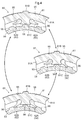
第一SOWC60は、係合片62とスプライン歯96との機械的な噛み合いの有無により、第一サンギヤS1が双方向に回転するのを許容するフリー状態と第一サンギヤS1の回転を阻止するロック状態とに少なくとも切替可能な、“噛み合い式係合装置”の一種である。本実施形態の第一SOWC60は、さらにワンウェイ状態にも切替可能であり、フリー状態(図4上段)とワンウェイ状態(図4中段)とロック状態(図4下段)とに切替可能となっている。フリー状態は、一対の係合片62A,62Bの両方がスプライン歯96に非係合となって実現される。ワンウェイ状態は、一対の係合片62A,62Bのうちの一方(図示の例では係合片62Aであるが、規制する回転方向に応じて係合片62Bとしても良い)がスプライン歯96に対して周方向の一方側から係合して実現される。ロック状態は、一対の係合片62A,62Bがスプライン歯96に対して周方向の両側から係合して実現される。本実施形態では、第一SOWC60が「噛み合い式係合装置」に相当する。
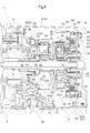
図3及び図5に示すように、第二SOWC65は、アウターレース66と、係合片67とを有する。本実施形態では、係合片67が「係合部」に相当する。アウターレース66は、円筒状の本体部66Aと、本体部66Aから径方向外側に突出する外側係合部66Bとを含む。また、アウターレース66は、係合片67を揺動自在に保持する保持部66Cを含む。係合片67は、第一係合片67Aと第二係合片67Bとを有する。対をなす第一係合片67Aと第二係合片67Bとは、互いに反対向きに傾斜するように設けられている。第一係合片67A及び第二係合片67Bは、アクチュエータにより切替レバー68を操作することで、それぞれ、保持部66Cによって保持された基端部を中心として径方向に揺動可能に構成されている。
第二SOWC65のアウターレース66は、ケース2の中間支持壁26の円筒状部27によって支持されている。アウターレース66は、その外周部にある外側係合部66Bが円筒状部27に形成されたスプライン歯97に係合することで、回転が規制された状態で支持されている。また、アウターレース66(保持部66C)は、後述するリングギヤ連結部材40の支持部42によって径方向内側から支持されている。一対の係合片67(第一係合片67A及び第二係合片67B)は、それぞれ、全体が保持部66Cの最内周面よりも径方向外側に収まる状態(収納状態;図3における第二係合片67Bの状態)と、先端部が保持部66Cの最内周面よりも径方向内側に突出する状態(突出状態;図3における第一係合片67Aの状態)とに切替可能である。そして、一対の係合片67(第一係合片67A及び第二係合片67B)は、突出状態で、リングギヤ連結部材40の中間円筒状部45に形成されたスプライン歯98に対して、周方向における互いに反対側から係合可能となっている。なお、上述したように一対の係合片67は突出状態で中間円筒状部45に形成されたスプライン歯98に対して直接係合可能なので、第二SOWC65にはインナーレースは設けられていない。
第二SOWC65は、係合片67とスプライン歯98との機械的な噛み合いの有無により、第二リングギヤR2が双方向に回転するのを許容するフリー状態と第二リングギヤR2の回転を阻止するロック状態とに少なくとも切替可能な、“噛み合い式係合装置”の一種である。本実施形態の第二SOWC65は、第一SOWC60と同様、さらにワンウェイ状態にも切替可能であり、フリー状態とワンウェイ状態とロック状態とに切替可能となっている。フリー状態は、一対の係合片67の両方がスプライン歯98に非係合となって実現される。ワンウェイ状態は、一対の係合片67のうちの一方がスプライン歯98に対して周方向の一方側から係合して実現される。ロック状態は、一対の係合片67がスプライン歯98に対して周方向の両側から係合して実現される。
第一遊星歯車装置PG1は、ブレーキBの係合状態又は第一SOWC60のワンウェイ状態若しくはロック状態で、第一リングギヤR1に入力される回転電機MGの回転を減速して第一キャリヤCA1から出力する(減速段)。また、第一遊星歯車装置PG1は、クラッチCの係合状態で、第一リングギヤR1に入力される回転電機MGの回転をそのままの回転速度で第一キャリヤCA1から出力する(直結段)。このように、本実施形態の第一遊星歯車装置PG1は、複数の変速段(直結段/減速段)を切替可能に構成されている。
第二遊星歯車装置PG2は、第二SOWC65のワンウェイ状態又はロック状態で、第一キャリヤCA1から中間連結部材33を介して第二サンギヤS2に入力される回転を、減速して出力部材Oから出力する。また、第二遊星歯車装置PG2は、第二SOWC65のフリー状態で、動力伝達経路における第二遊星歯車装置PG2よりも上流側(回転電機MG側)の各構成と、車輪Wとを切り離す。
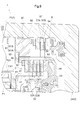
回転電機MG、出力部材O、第一遊星歯車装置PG1、第二遊星歯車装置PG2、クラッチC、ブレーキB、第一SOWC60、及び第二SOWC65は、ケース2内に収容されている。図5~図7に示すように、ケース2は、周壁21と、端部支持壁24と、中間支持壁26とを有する。周壁21は、回転電機MG、出力部材O、第一遊星歯車装置PG1、第二遊星歯車装置PG2、ブレーキB、及び第一SOWC60の外周を覆う筒状に形成されている。軸方向における周壁21の一方側の端部領域には、円筒状の内周面を有する円筒状面部22が形成されている。
この円筒状面部22には、スプライン歯94及びスプライン歯95が形成されている。これらのスプライン歯94とスプライン歯95とは、軸方向に連続して一体的に形成されている。別の言い方をすれば、周壁21の円筒状面部22には、スプライン歯94及びスプライン歯95の両方として機能する“第二共用スプライン歯”が形成されている。この第二共用スプライン歯に、第一SOWC60のアウターレース61とブレーキBの外側摩擦板57Bとが、軸方向に並ぶ状態で共通に支持されている。
端部支持壁24は、軸方向における周壁21の一方側(回転電機MGとは反対側)の端部を覆う板状に形成されている。なお、ケース2は、軸方向における周壁21の他方側(回転電機MG側)の端部を覆う第2の端部支持壁(図示せず)も備えている。中間支持壁26は、軸方向における出力部材Oと第二遊星歯車装置PG2との間を、全体として径方向に延びるように形成されている。中間支持壁26は、軸方向に突出する円筒状の円筒状部27を有する。円筒状部27は、中間支持壁26から第二遊星歯車装置PG2側に向かって突出するように形成されている。
図5に示すように、出力部材O、第二SOWC65、第二遊星歯車装置PG2、第一遊星歯車装置PG1、第一SOWC60、クラッチC、及びブレーキBは、同軸に配置されている。これらは、概ね記載の順に軸方向に並んで配置されている。図5及び図6に示すように、第一遊星歯車装置PG1及び第二遊星歯車装置PG2よりも端部支持壁24側では、第一SOWC60及びブレーキBが、軸方向に並んだ状態で、クラッチCに対して径方向外側に配置されている。本実施形態では、クラッチドラム兼用のブレーキハブ56の径方向内側にクラッチCが配置され、ブレーキハブ56の径方向外側に第一SOWC60及びブレーキBが配置されている。
そして、ブレーキハブ56の外周面に、スプライン歯93とスプライン歯96とが、軸方向に連続して一体的に形成されている。別の言い方をすれば、ブレーキハブ56の外周面には、スプライン歯93及びスプライン歯96の両方として機能する“第一共用スプライン歯”が形成されている。この第一共用スプライン歯に、第一SOWC60のアウターレース61とブレーキBの外側摩擦板57Bとが軸方向に並ぶ状態で共通に支持されているとともに、第一SOWC60の係合片62が揺動して突出状態となったときに係合可能となっている。
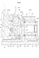
図5及び図7に示すように、第一遊星歯車装置PG1及び第二遊星歯車装置PG2よりも中間支持壁26側では、第二キャリヤCAがキャリヤ連結部材34を介して出力部材Oに連結されている。キャリヤ連結部材34は、ロータ軸10よりも大径の中空軸として形成されており、その内部をロータ軸10が貫通している。出力部材Oは、キャリヤ連結部材34よりも大径の中空軸として形成されており、その内部をロータ軸10が貫通しているとともに、キャリヤ連結部材34の一方の端部が挿入されている。
出力部材Oは、出力ギヤ72が形成された円筒状の本体部71と、本体部71から軸方向に突出する円筒状の円筒状部73とを有する。出力ギヤ72は、本体部71の外周面における中央領域に形成されている。円筒状部73は、本体部71から軸方向において第二遊星歯車装置PG2側に突出するように形成されている。また、円筒状部73は、本体部71よりも小径に形成されている。出力部材Oは、出力ギヤ72が形成された中央領域から、円筒状部73の先端側に向けて、段階的に小径となる段付き円筒状に形成されている。出力部材Oは、出力ギヤ72の両側で本体部71の外周面に嵌合された軸受81により、ケース2(中間支持壁26)に対して回転可能な状態で径方向に支持されている。
第二リングギヤR2が形成されたリングギヤ形成部材35は、リングギヤ連結部材40に連結されている。リングギヤ形成部材35は、少なくともリングギヤ連結部材40を介して、中間支持壁26に支持されている。リングギヤ連結部材40は、リングギヤ形成部材35に連結されて当該リングギヤ形成部材35(及び第二リングギヤR2)と一体回転する。リングギヤ連結部材40は、径方向延在部41と支持部42とを有している。
径方向延在部41は、リングギヤ形成部材35から径方向に延びるように形成されている。径方向延在部41は、概ね、第二遊星歯車装置PG2側から出力部材O側に向かって段階的に小径となる段付き円板状に形成されている。径方向延在部41は、外側円筒状部43と、外側円環板状部44と、中間円筒状部45と、中間円環板状部46と、内側円筒状部47と、内側円環板状部48とを有する。これらは一体的に形成されている。外側円筒状部43は、円筒状に形成されており、第二遊星歯車装置PG2側の端部でリングギヤ形成部材35と一体回転するように当該リングギヤ形成部材35に連結されている。外側円環板状部44は、円環板状に形成されており、外側円筒状部43の中間支持壁26側の端部から下方に延びている。
中間円筒状部45は、円筒状に形成されており、外側円環板状部44の下端部から、軸方向において中間支持壁26側に延びている。中間円環板状部46は、円環板状に形成されており、中間円筒状部45の中間支持壁26側の端部から下方に延びている。内側円筒状部47は、円筒状に形成されており、中間円環板状部46の下端部から、軸方向の両側に延びている。内側円筒状部47は、軸方向において出力部材O側及び第二遊星歯車装置PG2側の両方に突出している。内側円環板状部48は、円環板状に形成されており、内側円筒状部47の第二遊星歯車装置PG2側の端部付近から下方に延びている。
本実施形態では、リングギヤ連結部材40(並びにリングギヤ形成部材35及び第二リングギヤR2)は、軸受82により、出力部材Oに対して回転可能な状態で径方向に支持されている。本実施形態では、リングギヤ連結部材40と出力部材Oとが径方向に見て重複する部分を有しており、それらの重複部どうしの径方向の間に軸受82が配置されている。具体的には、リングギヤ連結部材40の内側円筒状部47と出力部材Oの円筒状部73とが径方向に見て重複して配置されており、内側円筒状部47の内周面と円筒状部73の外周面との間に軸受82が配置されている。そして、リングギヤ連結部材40が、軸受82により、出力部材Oに対して回転可能な状態で径方向に支持されている。
本実施形態では、軸受82は、出力部材Oの本体部71に対して、軸方向における第二遊星歯車装置PG2側に配置されている。また、軸受82は、ケース2(中間支持壁26)に対して出力部材Oを回転可能に支持する軸受81に対して、軸方向における第二遊星歯車装置PG2側に配置されている。さらに、軸受82は、軸受81に対して、径方向内側に配置されている。
また、リングギヤ連結部材40は、軸受83により、ケース2(中間支持壁26)に対して回転可能な状態で軸方向に支持されている。軸受83は、中間支持壁26の径方向内側の端部とリングギヤ連結部材40の中間円環板状部46との軸方向の間に配置されている。軸受83は、出力ギヤ72及び軸受81と軸方向に見て重複する位置に配置されている。また、軸受83は、内側円筒状部47、軸受82、及び円筒状部73と径方向に見て重複する位置に配置されている。さらに、リングギヤ連結部材40の内側円環板状部48とキャリヤ連結部材34のフランジ部との軸方向の間に、軸受84が配置されている。
リングギヤ連結部材40に設けられた支持部42は、第二SOWC65を支持する部位である。本実施形態では、リングギヤ連結部材40を構成する径方向延在部41の中間円筒状部45の外面に、支持部42が設けられている。この支持部42は、第二リングギヤR2の内周面よりも径方向内側に配置されている。また、支持部42における第二SOWC65の支持面は、第二キャリヤCA2の外周面よりも径方向内側に配置されている。
中間円筒状部45の径方向外側であって当該中間円筒状部45と径方向に見て重複する位置に、円筒状部27が配置されている。円筒状部27は、リングギヤ形成部材35よりも僅かに大径に形成されており、その内周面に形成されたスプライン歯97がリングギヤ形成部材35と軸方向に見て重複している。そして、その円筒状部27の内面に、第二SOWC65が支持されている。第二SOWC65は、アウターレース66の外側係合部66Bが円筒状部27の内周面に形成されたスプライン歯97に係合し、アウターレース66の保持部66Cが中間円筒状部45に形成されたスプライン歯98に支持される状態で配置されている。
〔その他の実施形態〕
(1)上記の実施形態では、第一SOWC60及び第二SOWC65が、それぞれフリー状態とワンウェイ状態とロック状態とに切替可能な構成を例として説明した。しかし、そのような構成に限定されることなく、第一SOWC60及び第二SOWC65の少なくとも一方が、フリー状態、ワンウェイ状態、及びロック状態のうちの2つの状態だけを切替可能に構成されても良い。
(1)上記の実施形態では、第一SOWC60及び第二SOWC65が、それぞれフリー状態とワンウェイ状態とロック状態とに切替可能な構成を例として説明した。しかし、そのような構成に限定されることなく、第一SOWC60及び第二SOWC65の少なくとも一方が、フリー状態、ワンウェイ状態、及びロック状態のうちの2つの状態だけを切替可能に構成されても良い。
(2)上記の実施形態では、第一SOWC60及び第二SOWC65が、それぞれアウターレース61,66と揺動自在な一対の係合片62,67とを有する構成を例として説明した。しかし、そのような構成に限定されることなく、第一SOWC60及び第二SOWC65の少なくとも一方に代えて、例えばドグクラッチ等の他の形式の噛み合い式係合装置が用いられても良い。
(3)上記の実施形態では、ブレーキBのブレーキハブ56がクラッチCのクラッチドラムに兼用されている構成を例として説明した。しかし、そのような構成に限定されることなく、クラッチドラムとブレーキハブ56とが別々に設けられても良い。
(4)上記の実施形態では、複数の変速段として直結段と減速段とを切替可能な第一遊星歯車装置PG1を備えている構成を例として説明した。しかし、そのような構成に限定されることなく、第一遊星歯車装置PG1が、複数の変速段として直結段と増速段とを切替可能であっても良い。また、第一遊星歯車装置PG1が、変速段を3段以上に切替可能であっても良い。また、第一遊星歯車装置PG1が、変速比固定の変速装置であっても良い。さらに、第一遊星歯車装置PG1が設けられなくても良い。
(5)上記の実施形態では、ケース2の周壁21の円筒状面部22に、スプライン歯94とスプライン歯95とが軸方向に連続して一体的に形成されている構成を例として説明した。しかし、そのような構成に限定されることなく、スプライン歯94とスプライン歯95とが別々に形成されても良い。
(6)上記の実施形態では、リングギヤ連結部材40が、軸受82により、出力部材Oに対して径方向に支持されている構成を例として説明した。しかし、そのような構成に限定されることなく、リングギヤ連結部材40が、ケース2(中間支持壁26)に対して径方向に支持されても良い。
(7)上記の実施形態では、リングギヤ連結部材40に設けられた支持部42が第二リングギヤR2の内周面よりも径方向内側に配置されている構成を例として説明した。しかし、そのような構成に限定されることなく、支持部42は、第二リングギヤR2の内周面と同じ径方向位置に配置されても良いし、第二リングギヤR2の内周面よりも径方向外側に配置されても良い。
(8)上記の実施形態では、第一SOWC60の状態(フリー状態/ワンウェイ状態/ロック状態)を切り替えるための一対の係合片62が径方向に揺動可能な構成を例として説明した。しかし、そのような構成に限定されることなく、一対の係合片62が軸方向に揺動可能な構成の第一SOWC60を用いても良い。第二SOWC65の具体的構成に関しても同様である。
(9)上記の実施形態では、サンギヤ連結部材32がブレーキハブ56よりも肉厚に形成され、ブレーキハブ56が肉厚のサンギヤ連結部材32を介してケース2に支持されている構成を例として説明した。しかし、そのような構成に限定されることなく、サンギヤ連結部材32はブレーキハブ56と同程度の厚さに形成されても良いし、サンギヤ連結部材32がブレーキハブ56よりも肉薄に形成されても良い。
(10)上述した各実施形態(上記の実施形態及びその他の実施形態を含む;以下同様)で開示される構成は、矛盾が生じない限り、他の実施形態で開示される構成と組み合わせて適用することも可能である。その他の構成に関しても、本明細書において開示された実施形態は全ての点で例示であって、本開示の趣旨を逸脱しない範囲内で適宜改変することが可能である。
〔実施形態の概要〕
以上をまとめると、本開示に係る車両用駆動装置は、好適には、以下の各構成を備える。
以上をまとめると、本開示に係る車両用駆動装置は、好適には、以下の各構成を備える。
車両用駆動装置(1)であって、
駆動力源(MG)に駆動連結される入力部材(10)と、
車輪(W)に駆動連結される出力部材(O)と、
前記入力部材(10)と前記出力部材(O)とを結ぶ動力伝達経路に設けられた、摩擦係合装置(B)及び噛み合い式係合装置(60)と、を備え、
前記摩擦係合装置(B)は、軸方向に並んで配置される一対の摩擦板(57)を有し、一対の前記摩擦板(57)のうちの一方が、筒状部材(56)に設けられた第一スプライン歯(93)に係合することで回転が規制され、
前記噛み合い式係合装置(60)は、係合部(62)を有し、前記係合部(62)が前記筒状部材(56)に設けられた第二スプライン歯(96)に対して係合及び係合解除するように構成され、
前記筒状部材(56)の外周面に、前記第一スプライン歯(93)と前記第二スプライン歯(96)とが、軸方向に連続して一体的に形成されている。
駆動力源(MG)に駆動連結される入力部材(10)と、
車輪(W)に駆動連結される出力部材(O)と、
前記入力部材(10)と前記出力部材(O)とを結ぶ動力伝達経路に設けられた、摩擦係合装置(B)及び噛み合い式係合装置(60)と、を備え、
前記摩擦係合装置(B)は、軸方向に並んで配置される一対の摩擦板(57)を有し、一対の前記摩擦板(57)のうちの一方が、筒状部材(56)に設けられた第一スプライン歯(93)に係合することで回転が規制され、
前記噛み合い式係合装置(60)は、係合部(62)を有し、前記係合部(62)が前記筒状部材(56)に設けられた第二スプライン歯(96)に対して係合及び係合解除するように構成され、
前記筒状部材(56)の外周面に、前記第一スプライン歯(93)と前記第二スプライン歯(96)とが、軸方向に連続して一体的に形成されている。
この構成によれば、摩擦係合装置(B)と噛み合い式係合装置(60)とが、いずれもスプライン歯(第一スプライン歯(93)/第二スプライン歯(96))に係合する部品を有するため、筒状部材(56)の外周面にスプライン歯を形成するだけで良く、別々の部品を準備する必要がない。よって、部品点数の低減を図ることができる。しかも、摩擦係合装置(B)のための第一スプライン歯(93)と噛み合い式係合装置(60)のための第二スプライン歯(96)とが軸方向に連続して一体的に形成され、共用化されるので、それらを一度の加工でまとめて形成することができる。よって、加工費を低く抑えてコスト低減を図ることができる。
一態様として、
前記係合部(62)は、前記第二スプライン歯(96)に対して周方向における互いに反対側から係合可能な一対の係合片(62)を有し、
前記噛み合い式係合装置(60)は、一対の前記係合片(62)が前記第二スプライン歯(96)に対して周方向の両側から係合して実現されるロック状態と、一対の前記係合片(62)のうちの一方が前記第二スプライン歯(96)に対して周方向の一方側から係合して実現されるワンウェイ状態と、一対の前記係合片(62)の両方が前記第二スプライン歯(96)に非係合となって実現されるフリー状態と、のうちの少なくとも2つの状態を切替可能に構成されていることが好ましい。
前記係合部(62)は、前記第二スプライン歯(96)に対して周方向における互いに反対側から係合可能な一対の係合片(62)を有し、
前記噛み合い式係合装置(60)は、一対の前記係合片(62)が前記第二スプライン歯(96)に対して周方向の両側から係合して実現されるロック状態と、一対の前記係合片(62)のうちの一方が前記第二スプライン歯(96)に対して周方向の一方側から係合して実現されるワンウェイ状態と、一対の前記係合片(62)の両方が前記第二スプライン歯(96)に非係合となって実現されるフリー状態と、のうちの少なくとも2つの状態を切替可能に構成されていることが好ましい。
この構成によれば、噛み合い式係合装置(60)が有する一対の係合片(62)の姿勢をそれぞれ制御するだけで簡単に、ロック状態、ワンウェイ状態、及びフリー状態のうちの少なくとも2つの状態を切り替えることができる。ロック状態で、噛み合い式係合装置(60)の両側の回転部材が同速で回転するようになり、ワンウェイ状態で、噛み合い式係合装置(60)の両側の回転部材がそれらの相対回転速度に応じて同速で回転又は相対回転するようになり、フリー状態で、噛み合い式係合装置(60)の両側の回転部材が相対回転するようになる。これらを切り替えることで、例えば複数の異なる変速比を実現することができる。
一態様として、
前記噛み合い式係合装置(60)は、セレクタブルワンウェイクラッチであることが好ましい。
前記噛み合い式係合装置(60)は、セレクタブルワンウェイクラッチであることが好ましい。
この構成によれば、コンパクトな機構により、ロック状態、ワンウェイ状態、及びフリー状態のうちの少なくとも2つの状態の切り替えを適切に行うことができる。
一態様として、
一対の前記係合片(62)が、径方向に揺動することにより、前記第二スプライン歯(96)に対する係合と非係合とを切り替えることが好ましい。
一対の前記係合片(62)が、径方向に揺動することにより、前記第二スプライン歯(96)に対する係合と非係合とを切り替えることが好ましい。
この構成によれば、径方向に揺動する一対の係合片(62)が第二スプライン歯(96)に直接係合可能なので、インナーレースを不要とすることができる。よって、噛み合い式係合装置(60)の構成の簡素化を図ることができる。
一態様として、
前記動力伝達経路に設けられた、前記摩擦係合装置(B)とは別の第二摩擦係合装置(C)をさらに備え、
前記第二摩擦係合装置(C)は、軸方向に並んで配置される一対の第二摩擦板(52)を有し、一対の前記第二摩擦板(52)のうちの一方が第三スプライン歯(92)に係合することで回転が規制され、
前記第三スプライン歯(92)が、前記筒状部材(56)の内周面に形成されていることが好ましい。
前記動力伝達経路に設けられた、前記摩擦係合装置(B)とは別の第二摩擦係合装置(C)をさらに備え、
前記第二摩擦係合装置(C)は、軸方向に並んで配置される一対の第二摩擦板(52)を有し、一対の前記第二摩擦板(52)のうちの一方が第三スプライン歯(92)に係合することで回転が規制され、
前記第三スプライン歯(92)が、前記筒状部材(56)の内周面に形成されていることが好ましい。
この構成によれば、第二摩擦係合装置(C)のための第三スプライン歯(92)が、共用化される第一スプライン歯(93)及び第二スプライン歯(96)と同じ、筒状部材(56)に形成される。外周面と内周面とに分かれるものの、単一の筒状部材(56)に対する連続的な加工で形成することができる。例えば第三スプライン歯(92)を筒状部材(56)とは別の部材に形成するような構成に比べて、構造の簡素化を図ることができるとともに、加工費を低く抑えることができる。
一態様として、
前記摩擦係合装置(B)及び前記噛み合い式係合装置(60)を収容するケース(2)を備え、
前記噛み合い式係合装置(60)は、アウターレース(61)を有し、当該アウターレース(61)の外周部が第四スプライン歯(95)に対して係合するように構成され、
前記摩擦係合装置(B)の一対の前記摩擦板(57)のうちの他方が第五スプライン歯(94)に係合することで回転が規制され、
前記ケース(2)の内面に形成された円筒状面部(22)に、前記第四スプライン歯(95)と前記第五スプライン歯(94)とが、軸方向に連続して一体的に形成されていることが好ましい。
前記摩擦係合装置(B)及び前記噛み合い式係合装置(60)を収容するケース(2)を備え、
前記噛み合い式係合装置(60)は、アウターレース(61)を有し、当該アウターレース(61)の外周部が第四スプライン歯(95)に対して係合するように構成され、
前記摩擦係合装置(B)の一対の前記摩擦板(57)のうちの他方が第五スプライン歯(94)に係合することで回転が規制され、
前記ケース(2)の内面に形成された円筒状面部(22)に、前記第四スプライン歯(95)と前記第五スプライン歯(94)とが、軸方向に連続して一体的に形成されていることが好ましい。
この構成によれば、摩擦係合装置(B)と噛み合い式係合装置(60)とが、いずれもスプライン歯(第四スプライン歯(95)/第五スプライン歯(94))に係合する部品を有するため、ケース(2)の内面に形成された円筒状面部(22)にスプライン歯を形成するだけで良く、いずれかのために別部品を別途準備する必要がない。よって、部品点数の低減を図ることができる。しかも、摩擦係合装置(B)のための第四スプライン歯(95)と噛み合い式係合装置(60)のための第五スプライン歯(94)とが軸方向に連続して一体的に形成され、共用化されるので、それらを一度の加工でまとめて形成することができる。よって、加工費を低く抑えてコスト低減を図ることができる。
一態様として、
前記摩擦係合装置(B)及び前記噛み合い式係合装置(60)を収容するケース(2)と、
前記入力部材(10)に駆動連結される第一回転要素(R1)と、前記出力部材(0)に駆動連結される第二回転要素(CA1)と、前記摩擦係合装置(B)及び前記噛み合い式係合装置(60)の少なくとも一方によって前記ケース(2)に選択的に固定される第三回転要素(S1)と、を有する遊星歯車装置(PG1)と、
前記第三回転要素(S1)に連結されて当該第三回転要素(S1)と一体回転する第三回転要素連結部材(32)と、を備え、
前記筒状部材(56)が、当該筒状部材(56)よりも肉厚に形成された前記第三回転要素連結部材(32)を介して前記ケース(2)に支持されていることが好ましい。
前記摩擦係合装置(B)及び前記噛み合い式係合装置(60)を収容するケース(2)と、
前記入力部材(10)に駆動連結される第一回転要素(R1)と、前記出力部材(0)に駆動連結される第二回転要素(CA1)と、前記摩擦係合装置(B)及び前記噛み合い式係合装置(60)の少なくとも一方によって前記ケース(2)に選択的に固定される第三回転要素(S1)と、を有する遊星歯車装置(PG1)と、
前記第三回転要素(S1)に連結されて当該第三回転要素(S1)と一体回転する第三回転要素連結部材(32)と、を備え、
前記筒状部材(56)が、当該筒状部材(56)よりも肉厚に形成された前記第三回転要素連結部材(32)を介して前記ケース(2)に支持されていることが好ましい。
この構成によれば、肉厚の第三回転要素連結部材(32)を介して、筒状部材(56)を安定良く支持することができる。その結果、摩擦係合装置(B)及び噛み合い式係合装置(60)を適切に支持することができる。
本開示に係る車両用駆動装置は、上述した各効果のうち、少なくとも1つを奏することができれば良い。
1 車両用駆動装置
2 ケース
10 ロータ軸(入力部材)
22 円筒状面部
26 中間支持壁(支持壁)
27 円筒状部(第二円筒状部)
32 サンギヤ連結部材(第三回転要素連結部材)
35 リングギヤ形成部材
40 リングギヤ連結部材
41 径方向延在部
42 支持部
45 中間円筒状部(第一円筒状部)
47 内側円筒状部
52 摩擦板(第二摩擦板)
52A 内側摩擦板
52B 外側摩擦板
56 ブレーキハブ(筒状部材)
57 摩擦板
57A 内側摩擦板
57B 外側摩擦板
60 第一SOWC(噛み合い式係合装置)
61 アウターレース
62 係合片(係合部)
62A 第一係合片
62B 第二係合片
65 第二SOWC(係合装置)
66 アウターレース
67 係合片(係合部)
71 本体部
72 出力ギヤ
73 円筒状部
81 軸受
82 軸受
92 スプライン歯(第三スプライン歯)
93 スプライン歯(第一スプライン歯)
94 スプライン歯(第五スプライン歯)
95 スプライン歯(第四スプライン歯)
96 スプライン歯(第二スプライン歯)
MG 回転電機(駆動力源)
PG1 第一遊星歯車装置(遊星歯車装置)
S1 第一サンギヤ(第三回転要素)
P1 第一ピニオンギヤ
CA1 第一キャリヤ(第二回転要素)
R1 第一リングギヤ(第一回転要素)
PG2 第二遊星歯車装置
S2 第二サンギヤ
P2 第二ピニオンギヤ
CA2 第二キャリヤ
R2 第二リングギヤ
C クラッチ(第二摩擦係合装置)
B ブレーキ(摩擦係合装置)
O 出力部材
W 車輪
2 ケース
10 ロータ軸(入力部材)
22 円筒状面部
26 中間支持壁(支持壁)
27 円筒状部(第二円筒状部)
32 サンギヤ連結部材(第三回転要素連結部材)
35 リングギヤ形成部材
40 リングギヤ連結部材
41 径方向延在部
42 支持部
45 中間円筒状部(第一円筒状部)
47 内側円筒状部
52 摩擦板(第二摩擦板)
52A 内側摩擦板
52B 外側摩擦板
56 ブレーキハブ(筒状部材)
57 摩擦板
57A 内側摩擦板
57B 外側摩擦板
60 第一SOWC(噛み合い式係合装置)
61 アウターレース
62 係合片(係合部)
62A 第一係合片
62B 第二係合片
65 第二SOWC(係合装置)
66 アウターレース
67 係合片(係合部)
71 本体部
72 出力ギヤ
73 円筒状部
81 軸受
82 軸受
92 スプライン歯(第三スプライン歯)
93 スプライン歯(第一スプライン歯)
94 スプライン歯(第五スプライン歯)
95 スプライン歯(第四スプライン歯)
96 スプライン歯(第二スプライン歯)
MG 回転電機(駆動力源)
PG1 第一遊星歯車装置(遊星歯車装置)
S1 第一サンギヤ(第三回転要素)
P1 第一ピニオンギヤ
CA1 第一キャリヤ(第二回転要素)
R1 第一リングギヤ(第一回転要素)
PG2 第二遊星歯車装置
S2 第二サンギヤ
P2 第二ピニオンギヤ
CA2 第二キャリヤ
R2 第二リングギヤ
C クラッチ(第二摩擦係合装置)
B ブレーキ(摩擦係合装置)
O 出力部材
W 車輪
Claims (7)
- 駆動力源に駆動連結される入力部材と、
車輪に駆動連結される出力部材と、
前記入力部材と前記出力部材とを結ぶ動力伝達経路に設けられた、摩擦係合装置及び噛み合い式係合装置と、を備え、
前記摩擦係合装置は、軸方向に並んで配置される一対の摩擦板を有し、一対の前記摩擦板のうちの一方が、筒状部材に設けられた第一スプライン歯に係合することで回転が規制され、
前記噛み合い式係合装置は、係合部を有し、前記係合部が前記筒状部材に設けられた第二スプライン歯に対して係合及び係合解除するように構成され、
前記筒状部材の外周面に、前記第一スプライン歯と前記第二スプライン歯とが、軸方向に連続して一体的に形成されている、車両用駆動装置。 - 前記係合部は、前記第二スプライン歯に対して周方向における互いに反対側から係合可能な一対の係合片を有し、
前記噛み合い式係合装置は、一対の前記係合片が前記第二スプライン歯に対して周方向の両側から係合して実現されるロック状態と、一対の前記係合片のうちの一方が前記第二スプライン歯に対して周方向の一方側から係合して実現されるワンウェイ状態と、一対の前記係合片の両方が前記第二スプライン歯に非係合となって実現されるフリー状態と、のうちの少なくとも2つの状態を切替可能に構成されている、請求項1に記載の車両用駆動装置。 - 前記噛み合い式係合装置は、セレクタブルワンウェイクラッチである、請求項2に記載の車両用駆動装置。
- 一対の前記係合片が、径方向に揺動することにより、前記第二スプライン歯に対する係合と非係合とを切り替える、請求項2又は3に記載の車両用駆動装置。
- 前記動力伝達経路に設けられた、前記摩擦係合装置とは別の第二摩擦係合装置をさらに備え、
前記第二摩擦係合装置は、軸方向に並んで配置される一対の第二摩擦板を有し、一対の前記第二摩擦板のうちの一方が第三スプライン歯に係合することで回転が規制され、
前記第三スプライン歯が、前記筒状部材の内周面に形成されている、請求項1から4のいずれか一項に記載の車両用駆動装置。 - 前記摩擦係合装置及び前記噛み合い式係合装置を収容するケースを備え、
前記噛み合い式係合装置は、アウターレースを有し、当該アウターレースの外周部が第四スプライン歯に対して係合するように構成され、
前記摩擦係合装置の一対の前記摩擦板のうちの他方が第五スプライン歯に係合することで回転が規制され、
前記ケースの内面に形成された円筒状面部に、前記第四スプライン歯と前記第五スプライン歯とが、軸方向に連続して一体的に形成されている、請求項1から5のいずれか一項に記載の車両用駆動装置。 - 前記摩擦係合装置及び前記噛み合い式係合装置を収容するケースと、
前記入力部材に駆動連結される第一回転要素と、前記出力部材に駆動連結される第二回転要素と、前記摩擦係合装置及び前記噛み合い式係合装置の少なくとも一方によって前記ケースに選択的に固定される第三回転要素と、を有する遊星歯車装置と、
前記第三回転要素に連結されて当該第三回転要素と一体回転する第三回転要素連結部材と、を備え、
前記筒状部材が、当該筒状部材よりも肉厚に形成された前記第三回転要素連結部材を介して前記ケースに支持されている、請求項1から6のいずれか一項に記載の車両用駆動装置。
Applications Claiming Priority (2)
| Application Number | Priority Date | Filing Date | Title |
|---|---|---|---|
| JP2018-216718 | 2018-11-19 | ||
| JP2018216718 | 2018-11-19 |
Publications (1)
| Publication Number | Publication Date |
|---|---|
| WO2020105636A1 true WO2020105636A1 (ja) | 2020-05-28 |
Family
ID=70774522
Family Applications (1)
| Application Number | Title | Priority Date | Filing Date |
|---|---|---|---|
| PCT/JP2019/045280 Ceased WO2020105636A1 (ja) | 2018-11-19 | 2019-11-19 | 車両用駆動装置 |
Country Status (1)
| Country | Link |
|---|---|
| WO (1) | WO2020105636A1 (ja) |
Cited By (2)
| Publication number | Priority date | Publication date | Assignee | Title |
|---|---|---|---|---|
| WO2023135870A1 (ja) * | 2022-01-13 | 2023-07-20 | 日本精工株式会社 | 動力伝達経路切換装置および2段変速機 |
| JPWO2023166802A1 (ja) * | 2022-03-01 | 2023-09-07 |
Citations (6)
| Publication number | Priority date | Publication date | Assignee | Title |
|---|---|---|---|---|
| JPH02138255U (ja) * | 1989-04-24 | 1990-11-19 | ||
| JPH07197949A (ja) * | 1993-12-28 | 1995-08-01 | Dainatsukusu:Kk | 一方向クラッチ機能を具えた摩擦係合装置 |
| JP2002039224A (ja) * | 2000-07-31 | 2002-02-06 | Honda Motor Co Ltd | ワンウェイクラッチ |
| JP2006250351A (ja) * | 2005-03-10 | 2006-09-21 | Ford Global Technologies Llc | 変速機の遊星歯車装置用キャリア組立体 |
| JP2009542990A (ja) * | 2006-07-07 | 2009-12-03 | ボーグワーナー・インコーポレーテッド | 2つのバッキングプレートを備える、ローラ、スプラグまたはラチェット型一方向クラッチ |
| JP2012219950A (ja) * | 2011-04-12 | 2012-11-12 | Nsk Ltd | 無段変速装置 |
-
2019
- 2019-11-19 WO PCT/JP2019/045280 patent/WO2020105636A1/ja not_active Ceased
Patent Citations (6)
| Publication number | Priority date | Publication date | Assignee | Title |
|---|---|---|---|---|
| JPH02138255U (ja) * | 1989-04-24 | 1990-11-19 | ||
| JPH07197949A (ja) * | 1993-12-28 | 1995-08-01 | Dainatsukusu:Kk | 一方向クラッチ機能を具えた摩擦係合装置 |
| JP2002039224A (ja) * | 2000-07-31 | 2002-02-06 | Honda Motor Co Ltd | ワンウェイクラッチ |
| JP2006250351A (ja) * | 2005-03-10 | 2006-09-21 | Ford Global Technologies Llc | 変速機の遊星歯車装置用キャリア組立体 |
| JP2009542990A (ja) * | 2006-07-07 | 2009-12-03 | ボーグワーナー・インコーポレーテッド | 2つのバッキングプレートを備える、ローラ、スプラグまたはラチェット型一方向クラッチ |
| JP2012219950A (ja) * | 2011-04-12 | 2012-11-12 | Nsk Ltd | 無段変速装置 |
Cited By (6)
| Publication number | Priority date | Publication date | Assignee | Title |
|---|---|---|---|---|
| WO2023135870A1 (ja) * | 2022-01-13 | 2023-07-20 | 日本精工株式会社 | 動力伝達経路切換装置および2段変速機 |
| JP7384319B1 (ja) * | 2022-01-13 | 2023-11-21 | 日本精工株式会社 | 動力伝達経路切換装置および2段変速機 |
| US12540647B2 (en) | 2022-01-13 | 2026-02-03 | Nsk Ltd. | Power transmission path switching device and two-speed transmission |
| JPWO2023166802A1 (ja) * | 2022-03-01 | 2023-09-07 | ||
| WO2023166802A1 (ja) * | 2022-03-01 | 2023-09-07 | ジヤトコ株式会社 | 装置 |
| JP7551272B2 (ja) | 2022-03-01 | 2024-09-17 | ジヤトコ株式会社 | 装置 |
Similar Documents
| Publication | Publication Date | Title |
|---|---|---|
| WO2020105635A1 (ja) | 車両用駆動装置 | |
| JP5842998B2 (ja) | 車両用変速機 | |
| JP7019280B2 (ja) | 動力伝達装置 | |
| US7998011B2 (en) | Speed change apparatus | |
| JP2015066993A (ja) | ハイブリッド駆動装置 | |
| JP6112231B2 (ja) | 自動変速機 | |
| JP2016175632A (ja) | 車両用駆動装置 | |
| JP2021162052A (ja) | 車両用駆動伝達装置 | |
| JP7218732B2 (ja) | 動力伝達装置 | |
| WO2018181557A1 (ja) | 車両用駆動装置 | |
| CN116194688A (zh) | 车用驱动装置 | |
| JP2020085052A (ja) | 車両用駆動装置 | |
| JP7619480B2 (ja) | 係合装置 | |
| JP2022169076A (ja) | 車両用動力伝達装置 | |
| JP7708326B2 (ja) | 変速機、及びそれを備えた車両用駆動伝達装置 | |
| JP7835312B2 (ja) | 車両用変速機 | |
| JP2019049320A (ja) | 車両用駆動装置 | |
| WO2024157852A1 (ja) | 係合装置、及びそれを備えた車両用駆動装置 | |
| JP2024043033A (ja) | 車両用駆動伝達装置 | |
| WO2025220730A1 (ja) | 2段変速機および電気自動車駆動装置 | |
| JP2024010429A (ja) | 車両用駆動伝達装置 | |
| JP2025153080A (ja) | 車両用駆動装置 | |
| JP2016179726A (ja) | 車両用駆動装置 | |
| CN118265855A (zh) | 接合装置 | |
| JP2022152833A (ja) | 車両用駆動装置 |
Legal Events
| Date | Code | Title | Description |
|---|---|---|---|
| 121 | Ep: the epo has been informed by wipo that ep was designated in this application |
Ref document number: 19887702 Country of ref document: EP Kind code of ref document: A1 |
|
| NENP | Non-entry into the national phase |
Ref country code: DE |
|
| 122 | Ep: pct application non-entry in european phase |
Ref document number: 19887702 Country of ref document: EP Kind code of ref document: A1 |
|
| NENP | Non-entry into the national phase |
Ref country code: JP |