WO2020105582A1 - トルク伝達軸 - Google Patents
トルク伝達軸Info
- Publication number
- WO2020105582A1 WO2020105582A1 PCT/JP2019/045052 JP2019045052W WO2020105582A1 WO 2020105582 A1 WO2020105582 A1 WO 2020105582A1 JP 2019045052 W JP2019045052 W JP 2019045052W WO 2020105582 A1 WO2020105582 A1 WO 2020105582A1
- Authority
- WO
- WIPO (PCT)
- Prior art keywords
- shaft
- axial
- axial direction
- torque transmission
- transmission shaft
- Prior art date
- Legal status (The legal status is an assumption and is not a legal conclusion. Google has not performed a legal analysis and makes no representation as to the accuracy of the status listed.)
- Ceased
Links
Images


Classifications
-
- B—PERFORMING OPERATIONS; TRANSPORTING
- B62—LAND VEHICLES FOR TRAVELLING OTHERWISE THAN ON RAILS
- B62D—MOTOR VEHICLES; TRAILERS
- B62D1/00—Steering controls, i.e. means for initiating a change of direction of the vehicle
- B62D1/02—Steering controls, i.e. means for initiating a change of direction of the vehicle vehicle-mounted
- B62D1/16—Steering columns
- B62D1/20—Connecting steering column to steering gear
-
- F—MECHANICAL ENGINEERING; LIGHTING; HEATING; WEAPONS; BLASTING
- F16—ENGINEERING ELEMENTS AND UNITS; GENERAL MEASURES FOR PRODUCING AND MAINTAINING EFFECTIVE FUNCTIONING OF MACHINES OR INSTALLATIONS; THERMAL INSULATION IN GENERAL
- F16C—SHAFTS; FLEXIBLE SHAFTS; ELEMENTS OR CRANKSHAFT MECHANISMS; ROTARY BODIES OTHER THAN GEARING ELEMENTS; BEARINGS
- F16C3/00—Shafts; Axles; Cranks; Eccentrics
- F16C3/02—Shafts; Axles
-
- F—MECHANICAL ENGINEERING; LIGHTING; HEATING; WEAPONS; BLASTING
- F16—ENGINEERING ELEMENTS AND UNITS; GENERAL MEASURES FOR PRODUCING AND MAINTAINING EFFECTIVE FUNCTIONING OF MACHINES OR INSTALLATIONS; THERMAL INSULATION IN GENERAL
- F16D—COUPLINGS FOR TRANSMITTING ROTATION; CLUTCHES; BRAKES
- F16D1/00—Couplings for rigidly connecting two coaxial shafts or other movable machine elements
- F16D1/02—Couplings for rigidly connecting two coaxial shafts or other movable machine elements for connecting two abutting shafts or the like
- F16D1/04—Couplings for rigidly connecting two coaxial shafts or other movable machine elements for connecting two abutting shafts or the like with clamping hub; with hub and longitudinal key
-
- F—MECHANICAL ENGINEERING; LIGHTING; HEATING; WEAPONS; BLASTING
- F16—ENGINEERING ELEMENTS AND UNITS; GENERAL MEASURES FOR PRODUCING AND MAINTAINING EFFECTIVE FUNCTIONING OF MACHINES OR INSTALLATIONS; THERMAL INSULATION IN GENERAL
- F16D—COUPLINGS FOR TRANSMITTING ROTATION; CLUTCHES; BRAKES
- F16D3/00—Yielding couplings, i.e. with means permitting movement between the connected parts during the drive
- F16D3/16—Universal joints in which flexibility is produced by means of pivots or sliding or rolling connecting parts
- F16D3/26—Hooke's joints or other joints with an equivalent intermediate member to which each coupling part is pivotally or slidably connected
- F16D3/38—Hooke's joints or other joints with an equivalent intermediate member to which each coupling part is pivotally or slidably connected with a single intermediate member with trunnions or bearings arranged on two axes perpendicular to one another
- F16D3/382—Hooke's joints or other joints with an equivalent intermediate member to which each coupling part is pivotally or slidably connected with a single intermediate member with trunnions or bearings arranged on two axes perpendicular to one another constructional details of other than the intermediate member
- F16D3/387—Fork construction; Mounting of fork on shaft; Adapting shaft for mounting of fork
-
- F—MECHANICAL ENGINEERING; LIGHTING; HEATING; WEAPONS; BLASTING
- F16—ENGINEERING ELEMENTS AND UNITS; GENERAL MEASURES FOR PRODUCING AND MAINTAINING EFFECTIVE FUNCTIONING OF MACHINES OR INSTALLATIONS; THERMAL INSULATION IN GENERAL
- F16D—COUPLINGS FOR TRANSMITTING ROTATION; CLUTCHES; BRAKES
- F16D3/00—Yielding couplings, i.e. with means permitting movement between the connected parts during the drive
- F16D3/16—Universal joints in which flexibility is produced by means of pivots or sliding or rolling connecting parts
- F16D3/26—Hooke's joints or other joints with an equivalent intermediate member to which each coupling part is pivotally or slidably connected
- F16D3/44—Hooke's joints or other joints with an equivalent intermediate member to which each coupling part is pivotally or slidably connected the intermediate member being connected to the coupling parts by ridges, pins, balls, or the like guided in grooves or between cogs
-
- F—MECHANICAL ENGINEERING; LIGHTING; HEATING; WEAPONS; BLASTING
- F16—ENGINEERING ELEMENTS AND UNITS; GENERAL MEASURES FOR PRODUCING AND MAINTAINING EFFECTIVE FUNCTIONING OF MACHINES OR INSTALLATIONS; THERMAL INSULATION IN GENERAL
- F16C—SHAFTS; FLEXIBLE SHAFTS; ELEMENTS OR CRANKSHAFT MECHANISMS; ROTARY BODIES OTHER THAN GEARING ELEMENTS; BEARINGS
- F16C2226/00—Joining parts; Fastening; Assembling or mounting parts
- F16C2226/50—Positive connections
- F16C2226/80—Positive connections with splines, serrations or similar profiles to prevent movement between joined parts
-
- F—MECHANICAL ENGINEERING; LIGHTING; HEATING; WEAPONS; BLASTING
- F16—ENGINEERING ELEMENTS AND UNITS; GENERAL MEASURES FOR PRODUCING AND MAINTAINING EFFECTIVE FUNCTIONING OF MACHINES OR INSTALLATIONS; THERMAL INSULATION IN GENERAL
- F16C—SHAFTS; FLEXIBLE SHAFTS; ELEMENTS OR CRANKSHAFT MECHANISMS; ROTARY BODIES OTHER THAN GEARING ELEMENTS; BEARINGS
- F16C2326/00—Articles relating to transporting
- F16C2326/20—Land vehicles
- F16C2326/24—Steering systems, e.g. steering rods or columns
-
- Y—GENERAL TAGGING OF NEW TECHNOLOGICAL DEVELOPMENTS; GENERAL TAGGING OF CROSS-SECTIONAL TECHNOLOGIES SPANNING OVER SEVERAL SECTIONS OF THE IPC; TECHNICAL SUBJECTS COVERED BY FORMER USPC CROSS-REFERENCE ART COLLECTIONS [XRACs] AND DIGESTS
- Y10—TECHNICAL SUBJECTS COVERED BY FORMER USPC
- Y10T—TECHNICAL SUBJECTS COVERED BY FORMER US CLASSIFICATION
- Y10T403/00—Joints and connections
- Y10T403/53—Split end with laterally movable opposed portions
- Y10T403/535—Split end with laterally movable opposed portions with separate force-applying means
-
- Y—GENERAL TAGGING OF NEW TECHNOLOGICAL DEVELOPMENTS; GENERAL TAGGING OF CROSS-SECTIONAL TECHNOLOGIES SPANNING OVER SEVERAL SECTIONS OF THE IPC; TECHNICAL SUBJECTS COVERED BY FORMER USPC CROSS-REFERENCE ART COLLECTIONS [XRACs] AND DIGESTS
- Y10—TECHNICAL SUBJECTS COVERED BY FORMER USPC
- Y10T—TECHNICAL SUBJECTS COVERED BY FORMER US CLASSIFICATION
- Y10T403/00—Joints and connections
- Y10T403/57—Distinct end coupler
- Y10T403/5761—Interrupted periphery, e.g., split or segmental, etc.
- Y10T403/5786—Split
-
- Y—GENERAL TAGGING OF NEW TECHNOLOGICAL DEVELOPMENTS; GENERAL TAGGING OF CROSS-SECTIONAL TECHNOLOGIES SPANNING OVER SEVERAL SECTIONS OF THE IPC; TECHNICAL SUBJECTS COVERED BY FORMER USPC CROSS-REFERENCE ART COLLECTIONS [XRACs] AND DIGESTS
- Y10—TECHNICAL SUBJECTS COVERED BY FORMER USPC
- Y10T—TECHNICAL SUBJECTS COVERED BY FORMER US CLASSIFICATION
- Y10T403/00—Joints and connections
- Y10T403/71—Rod side to plate or side
- Y10T403/7182—Yoke or ring-type connector
- Y10T403/7188—Rod received in open channel
Definitions
- the notch can be arranged on the other side in the axial direction with respect to the central axis of the mounting hole.
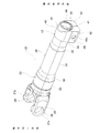
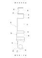
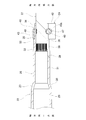
- a slit 39 extending in the axial direction is provided in a range corresponding to the axially other end side portion (the axially intermediate portion to the axially other end portion), which extends from the medium diameter tubular portion 31 to the small diameter tubular portion 33.
- the slit 39 communicates the inner peripheral surface and the outer peripheral surface of the shaft 23, and the phase (circumferential position) with respect to the pair of arm portions 27a and 27b forming the yoke portion 25 in the circumferential direction is deviated by 90 degrees. Placed in position.
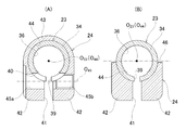
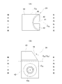
- the connecting portion 43 has a semi-cylindrical shape, and is provided with a notch 46 that is recessed from the other end surface in the axial direction of the flange portion 42 to the one side in the axial direction, in the portion on the other side in the axial direction.
- Notch 46 extending in the circumferential direction of the connecting portion 43 includes a central axis O 44 of the center axis O 23 and the insertion hole 44 of the shaft 23 and perpendicular to the mounting holes 45a, 45b center axis O 45 of It has a symmetrical shape with respect to the virtual plane.
- the notch 46 has a substantially triangular shape when viewed in the axial direction of the mounting holes 45a and 45b.
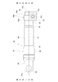
- the shaft 23 and the clamp 24 are fixed together.
- the structure for connecting and fixing the shaft 23 and the clamp 24 is not particularly limited, but, for example, a structure in which the shaft 23 and the clamp 24 are fixed by welding can be adopted.
- the convex (or concave) shaft-side engaging portion formed on the outer peripheral surface of the shaft 23 and the concave (or convex) clamp-side engaging portion formed on the inner peripheral surface of the clamp 24 are engaged and recessed.
- a structure in which the shaft side engaging portion or the clamp side engaging portion is plastically deformed (caulked) or the like can also be adopted. In any case, when the shaft 23 and the clamp 24 are fixed, relative rotation between the shaft 23 and the clamp 24 and relative displacement in the axial direction are prevented.
- the yoke portion 25 arranged at one axial end portion of the torque transmission shaft 22 is combined with another yoke and a cross shaft, not shown.
- the torque transmission shaft 22 is connected to the shaft such as the intermediate shaft having the other yoke so as to be able to transmit the torque.
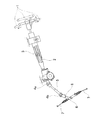
- the connecting portion arranged at one axial end of the torque transmission shaft is replaced with a yoke portion forming a universal joint, and other members such as a shaft are connected to the connecting portion. It is also possible to use a serration part, a spline part, or a key engaging part.
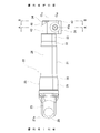
- the wall thickness of the portion of the small-diameter tubular portion 33 that is located on the one axial side of the fitting tubular portion 34 is larger than the wall thickness of the fitting tubular portion 34.
- the rigidity of one axial side portion is higher than the rigidity of the other axial side portion. Therefore, unlike the present example, when the diameter of the fitting tubular portion 34 is reduced by using a clamp having no notch in the connecting portion, the fitting tubular portion 34 is more axial than the axial one side portion. The part on the other side in the direction tends to be deformed more.
- the surface pressure between the inner peripheral surface of the fitting tubular portion 34 and the outer peripheral surface of the shaft 37 is greater than the axially one side portion (the tip side portion of the shaft 37) of the other axial side portion (the base of the shaft 37).
- the edge part) is higher. That is, the shaft 37 is strongly tightened at the other axial side portion of the fitting tubular portion 34, and is relatively loosely tightened at the axially one side portion thereof. Therefore, the shaft 37 easily precesses around the portion that is strongly tightened by the axially other side portion of the fitting tubular portion 34. When the precession movement of the shaft 37 occurs, fretting wear occurs at the serration engagement portion between the female serration 36 and the male serration 38, and the amount of wear tends to become excessive.
- the notch 46 is arranged on the other side in the axial direction with respect to the central axes of the mounting holes 45a and 45b, when the fitting tubular portion 34 is reduced in diameter by the clamp 24, the fitting portion with high rigidity is provided by the connecting portion 43.
- a large tightening force can be applied to the axially one side portion of the tubular portion 34. Therefore, it is possible to effectively increase the surface pressure between the inner peripheral surface of the one axial side portion of the fitting tubular portion 34 and the outer peripheral surface of the shaft 37.
Landscapes
- Engineering & Computer Science (AREA)
- General Engineering & Computer Science (AREA)
- Mechanical Engineering (AREA)
- Ocean & Marine Engineering (AREA)
- Chemical & Material Sciences (AREA)
- Combustion & Propulsion (AREA)
- Transportation (AREA)
- Steering Controls (AREA)
- Shafts, Cranks, Connecting Bars, And Related Bearings (AREA)
Priority Applications (3)
| Application Number | Priority Date | Filing Date | Title |
|---|---|---|---|
| CN201980077081.6A CN113167330B (zh) | 2018-11-22 | 2019-11-18 | 转矩传递轴 |
| JP2020558372A JP7400731B2 (ja) | 2018-11-22 | 2019-11-18 | トルク伝達軸 |
| US17/296,017 US11982319B2 (en) | 2018-11-22 | 2019-11-18 | Torque transmission shaft |
Applications Claiming Priority (2)
| Application Number | Priority Date | Filing Date | Title |
|---|---|---|---|
| JP2018219568 | 2018-11-22 | ||
| JP2018-219568 | 2018-11-22 |
Publications (1)
| Publication Number | Publication Date |
|---|---|
| WO2020105582A1 true WO2020105582A1 (ja) | 2020-05-28 |
Family
ID=70773686
Family Applications (1)
| Application Number | Title | Priority Date | Filing Date |
|---|---|---|---|
| PCT/JP2019/045052 Ceased WO2020105582A1 (ja) | 2018-11-22 | 2019-11-18 | トルク伝達軸 |
Country Status (4)
| Country | Link |
|---|---|
| US (1) | US11982319B2 (enExample) |
| JP (1) | JP7400731B2 (enExample) |
| CN (1) | CN113167330B (enExample) |
| WO (1) | WO2020105582A1 (enExample) |
Cited By (1)
| Publication number | Priority date | Publication date | Assignee | Title |
|---|---|---|---|---|
| JP7671053B2 (ja) | 2020-11-27 | 2025-05-01 | Nskステアリング&コントロール株式会社 | 中間シャフト |
Families Citing this family (2)
| Publication number | Priority date | Publication date | Assignee | Title |
|---|---|---|---|---|
| WO2020153408A1 (ja) * | 2019-01-23 | 2020-07-30 | 日本精工株式会社 | トルク伝達軸 |
| JP2022143667A (ja) * | 2021-03-18 | 2022-10-03 | 本田技研工業株式会社 | 車両用ステアリング装置及びその組立方法 |
Citations (4)
| Publication number | Priority date | Publication date | Assignee | Title |
|---|---|---|---|---|
| JPH01158826U (enExample) * | 1988-04-22 | 1989-11-02 | ||
| JPH09310724A (ja) * | 1996-05-22 | 1997-12-02 | Koyo Seiko Co Ltd | ユニバーサルジョイント用ボルトヨークアッセンブリ |
| JP2008155778A (ja) * | 2006-12-23 | 2008-07-10 | Koyo Mach Ind Co Ltd | ステアリング装置の動力伝達軸およびその組立方法 |
| JP2017172613A (ja) * | 2016-03-22 | 2017-09-28 | 日本精工株式会社 | 伸縮自在シャフト |
Family Cites Families (11)
| Publication number | Priority date | Publication date | Assignee | Title |
|---|---|---|---|---|
| GB191516053A (en) * | 1915-11-13 | 1916-11-09 | Moses Rosenbaum Comm Rosenbaum | Automatic Protective Gear for Electrical Systems. |
| US3923409A (en) * | 1975-01-22 | 1975-12-02 | Gen Motors Corp | Adjustable coupling clamp assembly |
| JP4070567B2 (ja) * | 2002-10-03 | 2008-04-02 | 日本精工株式会社 | 弾性自在継手 |
| JP4968114B2 (ja) * | 2008-03-04 | 2012-07-04 | 日本精工株式会社 | 自在継手 |
| JP5029723B2 (ja) | 2010-04-07 | 2012-09-19 | 日本精工株式会社 | 十字軸式自在継手用ヨーク及びその製造方法 |
| CN105473882B (zh) * | 2013-07-30 | 2018-10-12 | 日本精工株式会社 | 带有万向接头用叉轭的力矩传递轴及其制造方法和伸缩轴 |
| US10288125B2 (en) * | 2014-03-14 | 2019-05-14 | Nsk Ltd. | Torque transmission unit |
| JP6597010B2 (ja) | 2015-07-17 | 2019-10-30 | 日本精工株式会社 | 伸縮自在シャフトの製造方法 |
| US10738833B2 (en) * | 2017-06-29 | 2020-08-11 | Steering Solutions Ip Holding Corporation | Yoke to shaft attachment assembly |
| JP6690659B2 (ja) * | 2017-09-07 | 2020-04-28 | 日本精工株式会社 | トルク伝達軸 |
| WO2020153408A1 (ja) * | 2019-01-23 | 2020-07-30 | 日本精工株式会社 | トルク伝達軸 |
-
2019
- 2019-11-18 WO PCT/JP2019/045052 patent/WO2020105582A1/ja not_active Ceased
- 2019-11-18 CN CN201980077081.6A patent/CN113167330B/zh active Active
- 2019-11-18 US US17/296,017 patent/US11982319B2/en active Active
- 2019-11-18 JP JP2020558372A patent/JP7400731B2/ja active Active
Patent Citations (4)
| Publication number | Priority date | Publication date | Assignee | Title |
|---|---|---|---|---|
| JPH01158826U (enExample) * | 1988-04-22 | 1989-11-02 | ||
| JPH09310724A (ja) * | 1996-05-22 | 1997-12-02 | Koyo Seiko Co Ltd | ユニバーサルジョイント用ボルトヨークアッセンブリ |
| JP2008155778A (ja) * | 2006-12-23 | 2008-07-10 | Koyo Mach Ind Co Ltd | ステアリング装置の動力伝達軸およびその組立方法 |
| JP2017172613A (ja) * | 2016-03-22 | 2017-09-28 | 日本精工株式会社 | 伸縮自在シャフト |
Cited By (1)
| Publication number | Priority date | Publication date | Assignee | Title |
|---|---|---|---|---|
| JP7671053B2 (ja) | 2020-11-27 | 2025-05-01 | Nskステアリング&コントロール株式会社 | 中間シャフト |
Also Published As
| Publication number | Publication date |
|---|---|
| CN113167330B (zh) | 2023-12-22 |
| JPWO2020105582A1 (ja) | 2021-10-07 |
| CN113167330A (zh) | 2021-07-23 |
| US20220010841A1 (en) | 2022-01-13 |
| US11982319B2 (en) | 2024-05-14 |
| JP7400731B2 (ja) | 2023-12-19 |
Similar Documents
| Publication | Publication Date | Title |
|---|---|---|
| JP7400731B2 (ja) | トルク伝達軸 | |
| US11035414B2 (en) | Torque transmission shaft | |
| JP5088387B2 (ja) | 十字軸式自在継手 | |
| JP6673308B2 (ja) | ステアリング用トルク伝達軸 | |
| US12110927B2 (en) | Torque transmission shaft | |
| US20160108968A1 (en) | Stopper piece and bearing apparatus | |
| JP6642551B2 (ja) | トルク伝達軸 | |
| JP2017136889A (ja) | ステアリング装置 | |
| JP6673309B2 (ja) | トルク伝達軸 | |
| JP7099157B2 (ja) | シャフトとのクランプ部材との結合部、および、シャフトとクランプ部材との結合部の製造方法 | |
| JP7147509B2 (ja) | トルク伝達軸 | |
| JP5093284B2 (ja) | 十字軸式自在継手 | |
| CN111065835B (zh) | 扭矩传递轴 | |
| JP2020085111A (ja) | トルク伝達軸及びその製造方法 | |
| JP2022085813A (ja) | 中間シャフト | |
| JP2014238132A (ja) | 結合装置および結合装置を適用した車両用操舵装置 | |
| JP7067430B2 (ja) | 自在継手用ヨーク及び自在継手用ヨークと回転軸との結合構造 | |
| JP2025068994A (ja) | クランプ装置、該クランプ装置と回転軸との結合構造、及びステアリング装置 | |
| JP2025064736A (ja) | クランプ装置、該クランプ装置の製造方法、及びステアリング装置 | |
| JP4735444B2 (ja) | シャフトと自在継手のヨークとの結合部及びその製造方法 | |
| JP2025063510A (ja) | クランプ装置、該クランプ装置の製造方法、及びステアリング装置 | |
| US20210387664A1 (en) | Steering Column and Steering Device | |
| JP2022085543A (ja) | 中間シャフト | |
| JP2018128077A (ja) | ヨークとシャフトの結合構造 |
Legal Events
| Date | Code | Title | Description |
|---|---|---|---|
| 121 | Ep: the epo has been informed by wipo that ep was designated in this application |
Ref document number: 19886507 Country of ref document: EP Kind code of ref document: A1 |
|
| ENP | Entry into the national phase |
Ref document number: 2020558372 Country of ref document: JP Kind code of ref document: A |
|
| NENP | Non-entry into the national phase |
Ref country code: DE |
|
| 122 | Ep: pct application non-entry in european phase |
Ref document number: 19886507 Country of ref document: EP Kind code of ref document: A1 |