WO2020105582A1 - Torque transmission shaft - Google Patents
Torque transmission shaftInfo
- Publication number
- WO2020105582A1 WO2020105582A1 PCT/JP2019/045052 JP2019045052W WO2020105582A1 WO 2020105582 A1 WO2020105582 A1 WO 2020105582A1 JP 2019045052 W JP2019045052 W JP 2019045052W WO 2020105582 A1 WO2020105582 A1 WO 2020105582A1
- Authority
- WO
- WIPO (PCT)
- Prior art keywords
- shaft
- axial
- axial direction
- torque transmission
- transmission shaft
- Prior art date
Links
Images


Classifications
-
- B—PERFORMING OPERATIONS; TRANSPORTING
- B62—LAND VEHICLES FOR TRAVELLING OTHERWISE THAN ON RAILS
- B62D—MOTOR VEHICLES; TRAILERS
- B62D1/00—Steering controls, i.e. means for initiating a change of direction of the vehicle
- B62D1/02—Steering controls, i.e. means for initiating a change of direction of the vehicle vehicle-mounted
- B62D1/16—Steering columns
- B62D1/20—Connecting steering column to steering gear
-
- F—MECHANICAL ENGINEERING; LIGHTING; HEATING; WEAPONS; BLASTING
- F16—ENGINEERING ELEMENTS AND UNITS; GENERAL MEASURES FOR PRODUCING AND MAINTAINING EFFECTIVE FUNCTIONING OF MACHINES OR INSTALLATIONS; THERMAL INSULATION IN GENERAL
- F16C—SHAFTS; FLEXIBLE SHAFTS; ELEMENTS OR CRANKSHAFT MECHANISMS; ROTARY BODIES OTHER THAN GEARING ELEMENTS; BEARINGS
- F16C3/00—Shafts; Axles; Cranks; Eccentrics
- F16C3/02—Shafts; Axles
-
- F—MECHANICAL ENGINEERING; LIGHTING; HEATING; WEAPONS; BLASTING
- F16—ENGINEERING ELEMENTS AND UNITS; GENERAL MEASURES FOR PRODUCING AND MAINTAINING EFFECTIVE FUNCTIONING OF MACHINES OR INSTALLATIONS; THERMAL INSULATION IN GENERAL
- F16D—COUPLINGS FOR TRANSMITTING ROTATION; CLUTCHES; BRAKES
- F16D1/00—Couplings for rigidly connecting two coaxial shafts or other movable machine elements
- F16D1/02—Couplings for rigidly connecting two coaxial shafts or other movable machine elements for connecting two abutting shafts or the like
- F16D1/04—Couplings for rigidly connecting two coaxial shafts or other movable machine elements for connecting two abutting shafts or the like with clamping hub; with hub and longitudinal key
-
- F—MECHANICAL ENGINEERING; LIGHTING; HEATING; WEAPONS; BLASTING
- F16—ENGINEERING ELEMENTS AND UNITS; GENERAL MEASURES FOR PRODUCING AND MAINTAINING EFFECTIVE FUNCTIONING OF MACHINES OR INSTALLATIONS; THERMAL INSULATION IN GENERAL
- F16D—COUPLINGS FOR TRANSMITTING ROTATION; CLUTCHES; BRAKES
- F16D3/00—Yielding couplings, i.e. with means permitting movement between the connected parts during the drive
- F16D3/16—Universal joints in which flexibility is produced by means of pivots or sliding or rolling connecting parts
- F16D3/26—Hooke's joints or other joints with an equivalent intermediate member to which each coupling part is pivotally or slidably connected
- F16D3/38—Hooke's joints or other joints with an equivalent intermediate member to which each coupling part is pivotally or slidably connected with a single intermediate member with trunnions or bearings arranged on two axes perpendicular to one another
- F16D3/382—Hooke's joints or other joints with an equivalent intermediate member to which each coupling part is pivotally or slidably connected with a single intermediate member with trunnions or bearings arranged on two axes perpendicular to one another constructional details of other than the intermediate member
- F16D3/387—Fork construction; Mounting of fork on shaft; Adapting shaft for mounting of fork
-
- F—MECHANICAL ENGINEERING; LIGHTING; HEATING; WEAPONS; BLASTING
- F16—ENGINEERING ELEMENTS AND UNITS; GENERAL MEASURES FOR PRODUCING AND MAINTAINING EFFECTIVE FUNCTIONING OF MACHINES OR INSTALLATIONS; THERMAL INSULATION IN GENERAL
- F16D—COUPLINGS FOR TRANSMITTING ROTATION; CLUTCHES; BRAKES
- F16D3/00—Yielding couplings, i.e. with means permitting movement between the connected parts during the drive
- F16D3/16—Universal joints in which flexibility is produced by means of pivots or sliding or rolling connecting parts
- F16D3/26—Hooke's joints or other joints with an equivalent intermediate member to which each coupling part is pivotally or slidably connected
- F16D3/44—Hooke's joints or other joints with an equivalent intermediate member to which each coupling part is pivotally or slidably connected the intermediate member being connected to the coupling parts by ridges, pins, balls, or the like guided in grooves or between cogs
-
- F—MECHANICAL ENGINEERING; LIGHTING; HEATING; WEAPONS; BLASTING
- F16—ENGINEERING ELEMENTS AND UNITS; GENERAL MEASURES FOR PRODUCING AND MAINTAINING EFFECTIVE FUNCTIONING OF MACHINES OR INSTALLATIONS; THERMAL INSULATION IN GENERAL
- F16C—SHAFTS; FLEXIBLE SHAFTS; ELEMENTS OR CRANKSHAFT MECHANISMS; ROTARY BODIES OTHER THAN GEARING ELEMENTS; BEARINGS
- F16C2226/00—Joining parts; Fastening; Assembling or mounting parts
- F16C2226/50—Positive connections
- F16C2226/80—Positive connections with splines, serrations or similar profiles to prevent movement between joined parts
-
- F—MECHANICAL ENGINEERING; LIGHTING; HEATING; WEAPONS; BLASTING
- F16—ENGINEERING ELEMENTS AND UNITS; GENERAL MEASURES FOR PRODUCING AND MAINTAINING EFFECTIVE FUNCTIONING OF MACHINES OR INSTALLATIONS; THERMAL INSULATION IN GENERAL
- F16C—SHAFTS; FLEXIBLE SHAFTS; ELEMENTS OR CRANKSHAFT MECHANISMS; ROTARY BODIES OTHER THAN GEARING ELEMENTS; BEARINGS
- F16C2326/00—Articles relating to transporting
- F16C2326/20—Land vehicles
- F16C2326/24—Steering systems, e.g. steering rods or columns
-
- Y—GENERAL TAGGING OF NEW TECHNOLOGICAL DEVELOPMENTS; GENERAL TAGGING OF CROSS-SECTIONAL TECHNOLOGIES SPANNING OVER SEVERAL SECTIONS OF THE IPC; TECHNICAL SUBJECTS COVERED BY FORMER USPC CROSS-REFERENCE ART COLLECTIONS [XRACs] AND DIGESTS
- Y10—TECHNICAL SUBJECTS COVERED BY FORMER USPC
- Y10T—TECHNICAL SUBJECTS COVERED BY FORMER US CLASSIFICATION
- Y10T403/00—Joints and connections
- Y10T403/53—Split end with laterally movable opposed portions
- Y10T403/535—Split end with laterally movable opposed portions with separate force-applying means
-
- Y—GENERAL TAGGING OF NEW TECHNOLOGICAL DEVELOPMENTS; GENERAL TAGGING OF CROSS-SECTIONAL TECHNOLOGIES SPANNING OVER SEVERAL SECTIONS OF THE IPC; TECHNICAL SUBJECTS COVERED BY FORMER USPC CROSS-REFERENCE ART COLLECTIONS [XRACs] AND DIGESTS
- Y10—TECHNICAL SUBJECTS COVERED BY FORMER USPC
- Y10T—TECHNICAL SUBJECTS COVERED BY FORMER US CLASSIFICATION
- Y10T403/00—Joints and connections
- Y10T403/57—Distinct end coupler
- Y10T403/5761—Interrupted periphery, e.g., split or segmental, etc.
- Y10T403/5786—Split
-
- Y—GENERAL TAGGING OF NEW TECHNOLOGICAL DEVELOPMENTS; GENERAL TAGGING OF CROSS-SECTIONAL TECHNOLOGIES SPANNING OVER SEVERAL SECTIONS OF THE IPC; TECHNICAL SUBJECTS COVERED BY FORMER USPC CROSS-REFERENCE ART COLLECTIONS [XRACs] AND DIGESTS
- Y10—TECHNICAL SUBJECTS COVERED BY FORMER USPC
- Y10T—TECHNICAL SUBJECTS COVERED BY FORMER US CLASSIFICATION
- Y10T403/00—Joints and connections
- Y10T403/71—Rod side to plate or side
- Y10T403/7182—Yoke or ring-type connector
- Y10T403/7188—Rod received in open channel
Definitions
- the notch can be arranged on the other side in the axial direction with respect to the central axis of the mounting hole.
- a slit 39 extending in the axial direction is provided in a range corresponding to the axially other end side portion (the axially intermediate portion to the axially other end portion), which extends from the medium diameter tubular portion 31 to the small diameter tubular portion 33.
- the slit 39 communicates the inner peripheral surface and the outer peripheral surface of the shaft 23, and the phase (circumferential position) with respect to the pair of arm portions 27a and 27b forming the yoke portion 25 in the circumferential direction is deviated by 90 degrees. Placed in position.
- the connecting portion 43 has a semi-cylindrical shape, and is provided with a notch 46 that is recessed from the other end surface in the axial direction of the flange portion 42 to the one side in the axial direction, in the portion on the other side in the axial direction.
- Notch 46 extending in the circumferential direction of the connecting portion 43 includes a central axis O 44 of the center axis O 23 and the insertion hole 44 of the shaft 23 and perpendicular to the mounting holes 45a, 45b center axis O 45 of It has a symmetrical shape with respect to the virtual plane.
- the notch 46 has a substantially triangular shape when viewed in the axial direction of the mounting holes 45a and 45b.
- the shaft 23 and the clamp 24 are fixed together.
- the structure for connecting and fixing the shaft 23 and the clamp 24 is not particularly limited, but, for example, a structure in which the shaft 23 and the clamp 24 are fixed by welding can be adopted.
- the convex (or concave) shaft-side engaging portion formed on the outer peripheral surface of the shaft 23 and the concave (or convex) clamp-side engaging portion formed on the inner peripheral surface of the clamp 24 are engaged and recessed.
- a structure in which the shaft side engaging portion or the clamp side engaging portion is plastically deformed (caulked) or the like can also be adopted. In any case, when the shaft 23 and the clamp 24 are fixed, relative rotation between the shaft 23 and the clamp 24 and relative displacement in the axial direction are prevented.
- the yoke portion 25 arranged at one axial end portion of the torque transmission shaft 22 is combined with another yoke and a cross shaft, not shown.
- the torque transmission shaft 22 is connected to the shaft such as the intermediate shaft having the other yoke so as to be able to transmit the torque.
- the connecting portion arranged at one axial end of the torque transmission shaft is replaced with a yoke portion forming a universal joint, and other members such as a shaft are connected to the connecting portion. It is also possible to use a serration part, a spline part, or a key engaging part.
- the wall thickness of the portion of the small-diameter tubular portion 33 that is located on the one axial side of the fitting tubular portion 34 is larger than the wall thickness of the fitting tubular portion 34.
- the rigidity of one axial side portion is higher than the rigidity of the other axial side portion. Therefore, unlike the present example, when the diameter of the fitting tubular portion 34 is reduced by using a clamp having no notch in the connecting portion, the fitting tubular portion 34 is more axial than the axial one side portion. The part on the other side in the direction tends to be deformed more.
- the surface pressure between the inner peripheral surface of the fitting tubular portion 34 and the outer peripheral surface of the shaft 37 is greater than the axially one side portion (the tip side portion of the shaft 37) of the other axial side portion (the base of the shaft 37).
- the edge part) is higher. That is, the shaft 37 is strongly tightened at the other axial side portion of the fitting tubular portion 34, and is relatively loosely tightened at the axially one side portion thereof. Therefore, the shaft 37 easily precesses around the portion that is strongly tightened by the axially other side portion of the fitting tubular portion 34. When the precession movement of the shaft 37 occurs, fretting wear occurs at the serration engagement portion between the female serration 36 and the male serration 38, and the amount of wear tends to become excessive.
- the notch 46 is arranged on the other side in the axial direction with respect to the central axes of the mounting holes 45a and 45b, when the fitting tubular portion 34 is reduced in diameter by the clamp 24, the fitting portion with high rigidity is provided by the connecting portion 43.
- a large tightening force can be applied to the axially one side portion of the tubular portion 34. Therefore, it is possible to effectively increase the surface pressure between the inner peripheral surface of the one axial side portion of the fitting tubular portion 34 and the outer peripheral surface of the shaft 37.
Abstract
This torque transmission shaft has a hollow tubular shaft and a clamp. The shaft is provided with: a connection section integrated with the shaft on one axial end portion thereof; a slit, on the other axial side portion, extending in the axial direction thereof and open in the other axial side thereof; and female serration on the inner peripheral surface of the other axial end thereof. The clamp is provided with: a discontinuous section that is a separate body from the shaft and is provided at one position in the circumferential direction; a pair of flange sections on both sides of the discontinuous section; and a connection section that connects the pair of flange sections in the circumferential direction. The clamp is externally fitted and fixed to the other axial end portion of the shaft and reduces the diameter of the other axial end side portion of the shaft.
Description
本発明は、自動車用のステアリング装置などに組み込まれるトルク伝達軸に関する。
The present invention relates to a torque transmission shaft incorporated in a steering device for an automobile.
図11は、特開2017-25964号公報に記載された、自動車用のステアリング装置の従来例を示す。ステアリング装置は、ステアリングホイール1と、ステアリングシャフト2と、ステアリングコラム3と、1対の自在継手4a、4bと、中間シャフト5と、ステアリングギヤユニット6と、1対のタイロッド7とを備える。
FIG. 11 shows a conventional example of a steering device for an automobile, which is described in Japanese Patent Laid-Open No. 2017-25964. The steering device includes a steering wheel 1, a steering shaft 2, a steering column 3, a pair of universal joints 4 a and 4 b, an intermediate shaft 5, a steering gear unit 6, and a pair of tie rods 7.
ステアリングホイール1は、ステアリングコラム3の内側に回転自在に支持されたステアリングシャフト2の後端部に取り付けられる。ステアリングシャフト2の前端部は、1対の自在継手4a、4bおよび中間シャフト5を介して、ステアリングギヤユニット6のピニオン軸8に接続される。ピニオン軸8の回転が図示しないラックの直線運動に変換されて、1対のタイロッド7が押し引きされることにより、操舵輪にステアリングホイール1の操作量に応じた舵角が付与される。
The steering wheel 1 is attached to the rear end of the steering shaft 2 which is rotatably supported inside the steering column 3. The front end of the steering shaft 2 is connected to the pinion shaft 8 of the steering gear unit 6 via a pair of universal joints 4 a and 4 b and an intermediate shaft 5. The rotation of the pinion shaft 8 is converted into a linear motion of a rack (not shown), and the pair of tie rods 7 are pushed and pulled, so that the steered wheels are given a steering angle according to the operation amount of the steering wheel 1.
自在継手4a、4bは、互いに同一直線上に存在しない回転軸である、ステアリングシャフト2と中間シャフト5、並びに、中間シャフト5とピニオン軸8を、トルク伝達可能に接続する。自在継手4a、4bとしては、特開2011-220398号公報などに記載されている、1対のヨークと十字軸とを備えた自在継手が使用されている。
The universal joints 4a and 4b connect the steering shaft 2 and the intermediate shaft 5, and the intermediate shaft 5 and the pinion shaft 8, which are rotating shafts that do not exist on the same straight line, so that torque can be transmitted. As the universal joints 4a and 4b, the universal joints including a pair of yokes and a cross shaft described in JP 2011-220398 A are used.
大型の自動車に搭載されるステアリング装置にあっては、ステアリングシャフトからステアリングギヤユニットまでの距離が長い。このため、自在継手を構成するヨークに対して、ステアリングシャフトやピニオン軸などの軸を直接固定する代わりに、延長軸と呼ばれるトルク伝達軸を介して、前記軸を固定することが考えられる。
In the case of steering devices installed in large vehicles, the distance from the steering shaft to the steering gear unit is long. Therefore, instead of directly fixing a shaft such as a steering shaft or a pinion shaft to a yoke forming a universal joint, it is possible to fix the shaft via a torque transmission shaft called an extension shaft.
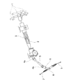
図12(A)~図12(C)は、本発明者らが先に考えたトルク伝達軸9を示す。トルク伝達軸9は、ヨーク10と、ステアリングシャフトやピニオン軸などの軸11との間に配置され、ヨーク10と軸11とをトルク伝達可能に接続する。トルク伝達軸9は、軸方向一端部の外周面に設けられた雄セレーション12と、軸方向他端部の内周面に設けられた雌セレーション13と、軸方向他端部に一体に設けられ、トルク伝達軸9の軸方向他端部を縮径するためのクランプ部14とを備える。クランプ部14は、トルク伝達軸9の軸方向他端部の円周方向1箇所に設けられた不連続部15と、不連続部15の両側に配置された1対のフランジ部16と、1対のフランジ部16に設けられ、図示しない締付部材を挿入可能な取付孔17とを備える。
12 (A) to 12 (C) show the torque transmission shaft 9 previously considered by the present inventors. The torque transmission shaft 9 is arranged between the yoke 10 and a shaft 11 such as a steering shaft or a pinion shaft, and connects the yoke 10 and the shaft 11 so that torque can be transmitted. The torque transmission shaft 9 is provided integrally with the male serration 12 provided on the outer peripheral surface at one end in the axial direction, the female serration 13 provided on the inner peripheral surface at the other end in the axial direction, and the other end at the other end in the axial direction. , And a clamp portion 14 for reducing the diameter of the other end portion of the torque transmission shaft 9 in the axial direction. The clamp portion 14 includes a discontinuous portion 15 provided at one position in the circumferential direction at the other axial end portion of the torque transmission shaft 9, a pair of flange portions 16 arranged on both sides of the discontinuous portion 15, and 1 The pair of flange portions 16 are provided with a mounting hole 17 into which a tightening member (not shown) can be inserted.
トルク伝達軸9の軸方向一端部は、ヨーク10を構成する基部18の内側に挿入される。雄セレーション12は、基部18の内周面に設けられた雌セレーション19とセレーション係合する。トルク伝達軸9と基部18は、溶接ビード部20により全周にわたり溶接固定される。
The one axial end portion of the torque transmission shaft 9 is inserted inside the base portion 18 forming the yoke 10. The male serration 12 is in serration engagement with a female serration 19 provided on the inner peripheral surface of the base portion 18. The torque transmission shaft 9 and the base portion 18 are welded and fixed to each other by the weld bead portion 20 over the entire circumference.
トルク伝達軸9の軸方向他端部の内側には、軸11の軸方向一端部が挿入される。雌セレーション13は、軸11の外周面に設けられた雄セレーション21とセレーション係合する。前記締付部材の先端部を取付孔17あるいは図示しないナットに螺合することにより、トルク伝達軸9の内周面により軸11の外周面は強く締め付けられる。
The one axial end of the shaft 11 is inserted inside the other axial end of the torque transmission shaft 9. The female serration 13 is in serration engagement with the male serration 21 provided on the outer peripheral surface of the shaft 11. The outer peripheral surface of the shaft 11 is strongly tightened by the inner peripheral surface of the torque transmission shaft 9 by screwing the tip portion of the tightening member into the mounting hole 17 or a nut (not shown).
トルク伝達軸9は、通常、冷間鍛造加工により造られる。熱間鍛造加工による場合に比べて、冷間鍛造加工により造られたトルク伝達軸9の形状精度および寸法精度は高い。しかしながら、トルク伝達軸9では、金属材料の流動が複雑になるクランプ部14が一体に設けられていることなどに起因して、トルク伝達軸9の軸方向両端部に設けられた雄セレーション12と雌セレーション13との同軸度を高度に確保することが難しい。また、トルク伝達軸9とヨーク10とが溶接固定されているため、熱変形などに起因して、トルク伝達軸9とヨーク10との同軸度が低くなりやすい。このため、図12(C)に示すように、トルク伝達軸9に接続される軸、すなわち、ヨーク10を介して接続される軸11a、あるいは、雌セレーション13に接続される軸11の振れ回りが大きくなる可能性がある。この結果、トルク伝達軸9が適用されたステアリング装置の一部で、トルク伝達軸9に接続された軸の振れ回りに起因して、回転方向の摺動異音、スティックスリップ振動異音などの異音が発生する可能性がある。
The torque transmission shaft 9 is usually made by cold forging. Compared to the case of hot forging, the torque transmission shaft 9 made by cold forging has high shape accuracy and dimensional accuracy. However, because the torque transmission shaft 9 is integrally provided with the clamp portion 14 that complicates the flow of the metal material, the male serrations 12 provided at both axial end portions of the torque transmission shaft 9 are combined with each other. It is difficult to secure a high degree of coaxiality with the female serration 13. Further, since the torque transmission shaft 9 and the yoke 10 are fixed by welding, the degree of coaxiality between the torque transmission shaft 9 and the yoke 10 tends to decrease due to thermal deformation or the like. Therefore, as shown in FIG. 12C, the whirling of the shaft connected to the torque transmission shaft 9, that is, the shaft 11a connected via the yoke 10 or the shaft 11 connected to the female serration 13 Can be large. As a result, in a part of the steering device to which the torque transmission shaft 9 is applied, due to whirling of the shaft connected to the torque transmission shaft 9, sliding noise, stick-slip vibration noise, etc. in the rotation direction may occur. Abnormal noise may occur.
本発明は、上述のような事情に鑑み、トルク伝達軸に接続される軸の振れ回りを抑えることができる、トルク伝達軸の構造を実現することを目的としている。
In view of the above-mentioned circumstances, the present invention has an object to realize a structure of a torque transmission shaft that can suppress whirling of a shaft connected to the torque transmission shaft.
本発明のトルク伝達軸は、シャフトと、該シャフトとは別体のクランプとを備える。
The torque transmission shaft of the present invention includes a shaft and a clamp separate from the shaft.
前記シャフトは、中空筒形状であり、軸方向一端部と、該軸方向一端部に備えられ、他の部材に対してトルク伝達可能に接続可能である接続部と、軸方向他端部と、軸方向他端側部分に備えられ、軸方向に伸長し、軸方向一方側の閉鎖端と軸方向他方側の開口端を有するスリットと、前記軸方向他端部の内周面に備えられた雌セレーションとを有する。前記接続部は、前記シャフトと一体に設けられる。
The shaft has a hollow cylindrical shape, one end in the axial direction, a connecting portion provided at the one end in the axial direction and connectable to another member so that torque can be transmitted, and the other end in the axial direction, A slit provided on the other end in the axial direction, extending in the axial direction, having a closed end on one side in the axial direction and an open end on the other side in the axial direction, and an inner peripheral surface of the other end in the axial direction. With female serrations. The connecting portion is provided integrally with the shaft.
前記クランプは、欠円筒形状であり、円周方向1箇所に配置された不連続部と、該不連続部を挟んで両側に配置され、締付部材が挿入可能な取付孔を有する1対のフランジ部と、および、部分円筒形状であり、前記1対のフランジ部を円周方向に連結する連結部とを有する。該クランプは、前記シャフトとは別体で、前記シャフトの前記軸方向他端部に外嵌固定されており、前記スリットの幅寸法を狭めることにより、前記シャフトの前記軸方向他端側部分を縮径させることが可能である。
The clamp has a shape of a hollow cylinder, and has a pair of discontinuous portions arranged at one location in the circumferential direction, and a pair of mounting holes arranged on both sides with the discontinuous portion sandwiched therebetween, into which a tightening member can be inserted. It has a flange portion and a connecting portion that is of a partially cylindrical shape and that connects the pair of flange portions in the circumferential direction. The clamp is a member separate from the shaft and is externally fitted and fixed to the other axial end portion of the shaft. By narrowing the width dimension of the slit, the other axial end portion of the shaft is fixed. It is possible to reduce the diameter.
前記クランプは、前記スリットの幅寸法を狭めた際に、前記シャフトの前記軸方向他端部のうちの軸方向一方側部分に対して、該軸方向他端部のうちの軸方向他方側部分よりも大きな締付力を付与するように構成されることができる。
When the width dimension of the slit is narrowed, the clamp has a portion on the other side in the axial direction of the other end portion in the axial direction with respect to a portion on the one side in the axial direction of the other end portion in the axial direction of the shaft. It can be configured to apply a greater tightening force.
具体的には、前記連結部は、該連結部の軸方向他方側部分に、前記フランジ部の軸方向他端面から軸方向一方側に凹んだ切り欠きを備える。
Specifically, the connecting portion is provided with a notch that is recessed from the other end surface in the axial direction of the flange portion to one side in the axial direction, in the axially other side portion of the connecting portion.
前記切り欠きは、前記取付孔の中心軸よりも軸方向他方側に配置されることができる。
The notch can be arranged on the other side in the axial direction with respect to the central axis of the mounting hole.
前記切り欠きは、前記連結部の円周方向に関して前記フランジ部から離れるほど、軸方向幅が大きくなる形状を有することができる。
The notch may have a shape in which the axial width increases with increasing distance from the flange portion in the circumferential direction of the connecting portion.
あるいは、前記切り欠きは、前記連結部の円周方向に関して軸方向幅が一定である形状を有することもできる。
Alternatively, the notch may have a shape with a constant axial width in the circumferential direction of the connecting portion.
前記連結部の円周方向に関する前記切り欠きの端部は、前記取付孔の中心軸および前記シャフトの中心軸にそれぞれ直交する方向に関して、前記シャフトの中心軸よりも前記取付孔に近い側に配置されることができる。
The end portion of the cutout in the circumferential direction of the connecting portion is arranged on a side closer to the mounting hole than the central axis of the shaft in directions orthogonal to the central axis of the mounting hole and the central axis of the shaft. Can be done.
前記切り欠きは、前記シャフトの中心軸を含み、かつ、前記取付孔の中心軸に直交する仮想平面に関して対称形状を有することができる。
The notch may have a symmetrical shape with respect to an imaginary plane that includes the central axis of the shaft and is orthogonal to the central axis of the mounting hole.
前記接続部は、自在継手を構成するヨーク部により構成されることができる。あるいは、前記接続部は、セレーション部、スプライン部、あるいは、キー係合部により構成されることができる。
The connection part can be configured by a yoke part that constitutes a universal joint. Alternatively, the connecting portion may be composed of a serration portion, a spline portion, or a key engaging portion.
本発明のトルク伝達軸では、トルク伝達軸の軸方向両端部に設けられた接続部と雌セレーションとの同軸度、並びに、トルク伝達軸と接続部との同軸度をいずれも高度に確保することができる。また、本発明のトルク伝達軸では、クランプにより、雌セレーション側に接続される軸を、該軸に歳差運動が生じないように締め付けることができる。このため、本発明のトルク伝達軸では、該トルク伝達軸に接続される軸の振れ回りを抑えることが可能となる。
In the torque transmission shaft of the present invention, both the coaxiality between the female serration and the connection portion provided at both axial ends of the torque transmission shaft, and the coaxiality between the torque transmission shaft and the connection portion are ensured to a high degree. You can Further, in the torque transmission shaft of the present invention, the shaft connected to the female serration side can be clamped by the clamp so as not to cause precession of the shaft. Therefore, in the torque transmission shaft of the present invention, whirling of the shaft connected to the torque transmission shaft can be suppressed.
[第1例]
本発明の実施の形態の第1例について、図1~図8を用いて説明する。本例のトルク伝達軸22は、例えば、大型の自動車のステアリング装置に組み込まれて、互いに同一直線上に存在しない回転軸である、ステアリングシャフトと中間シャフト、あるいは、中間シャフトとピニオン軸を、トルク伝達可能に接続するために使用される。 [First example]
A first example of the embodiment of the present invention will be described with reference to FIGS. 1 to 8. Thetorque transmission shaft 22 of the present example is incorporated in, for example, a steering device of a large automobile, and a steering shaft and an intermediate shaft, or an intermediate shaft and a pinion shaft, which are rotating shafts that do not exist on the same straight line, are connected to each other by a torque Used to connect communicatively.
本発明の実施の形態の第1例について、図1~図8を用いて説明する。本例のトルク伝達軸22は、例えば、大型の自動車のステアリング装置に組み込まれて、互いに同一直線上に存在しない回転軸である、ステアリングシャフトと中間シャフト、あるいは、中間シャフトとピニオン軸を、トルク伝達可能に接続するために使用される。 [First example]
A first example of the embodiment of the present invention will be described with reference to FIGS. 1 to 8. The
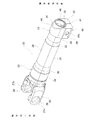
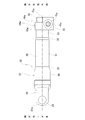
トルク伝達軸22は、中空筒形状のシャフト23と、シャフト23とは別体で、欠円筒形状(略U字状)のクランプ24とを備える。以下の説明において、軸方向とは、特に断らない限り、トルク伝達軸22の軸方向をいう。また、軸方向に関して一方(一端)側とは、図1、図2、図4、図5、図6、図7および図8では、左側である。軸方向に関して他方(他端)側とは、クランプ24が配置される側をいい、図1、図2、図4、図5、図6、図7および図8では、右側である。
The torque transmission shaft 22 includes a hollow cylindrical shaft 23 and a clamp 24 that is a separate body from the shaft 23 and has a hollow cylindrical shape (substantially U-shaped). In the following description, the axial direction means the axial direction of the torque transmission shaft 22 unless otherwise specified. Further, the one side (one end) side in the axial direction is the left side in FIGS. 1, 2, 4, 5, 6, 7, and 8. The other (the other end) side in the axial direction is the side where the clamp 24 is arranged, and is the right side in FIGS. 1, 2, 4, 5, 6, 7, and 8.
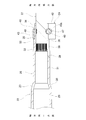
シャフト23は、炭素鋼鋳鋼材(SC材)などの素材に、鍛造加工(冷間鍛造加工または熱間鍛造加工)および切削加工などを施すことにより、全体を一体に造られている。シャフト23は、軸方向一端部と、該軸方向一端部に備えられ、他の部材に対してトルク伝達可能に接続可能である接続部とを備える。本例では、シャフト23の接続部は、二股状のヨーク部25により構成される。シャフト23の軸方向中間部から軸方向他端部までは、筒部26により構成される。
The shaft 23 is integrally manufactured by subjecting a material such as cast carbon steel (SC material) to forging (cold forging or hot forging) and cutting. The shaft 23 includes one end in the axial direction and a connecting portion that is provided at the one end in the axial direction and is connectable to another member so that torque can be transmitted. In this example, the connecting portion of the shaft 23 is formed of a bifurcated yoke portion 25. A tubular portion 26 is formed from the axially intermediate portion of the shaft 23 to the other axial end portion.
ヨーク部25は、十字軸式の自在継手を構成する。ヨーク部25は、腕部27a、27bを備える。腕部27a、27bは、筒部26の軸方向一端縁の直径方向反対側となる2箇所位置から軸方向一方側に伸長している。腕部27a、27bのそれぞれは、互いに同軸の円孔28を有する。円孔28の内側には、図示しない軸受カップおよびニードルが配置され、十字軸を構成する軸部が回転自在に支持される。
The yoke portion 25 constitutes a cross shaft type universal joint. The yoke portion 25 includes arm portions 27a and 27b. The arms 27a and 27b extend from one axial end to one axial end from two positions on the diametrically opposite sides of the axial end of the tubular portion 26. Each of the arms 27a and 27b has a circular hole 28 that is coaxial with each other. A bearing cup and a needle (not shown) are arranged inside the circular hole 28, and a shaft portion forming a cross shaft is rotatably supported.
筒部26は、中空筒形状を有し、軸方向一方側から順に、大径筒部29と、大径側円すい筒部30と、中径筒部31と、小径側円すい筒部32と、小径筒部33とを備える。
The tubular portion 26 has a hollow tubular shape, and has a large diameter tubular portion 29, a large diameter side conical tubular portion 30, a medium diameter tubular portion 31, and a small diameter side conical tubular portion 32 in order from one axial side. And a small-diameter cylindrical portion 33.
大径筒部29は、段付円筒形状を有し、筒部26の軸方向一端部に配置される。大径筒部29の軸方向他端縁は、大径側円すい筒部30の軸方向一端縁に接続する。大径筒部29の外径寸法および内径寸法は、大径筒部29の軸方向他方側に存在する、筒部26を構成するその他の部分の外径寸法および内径寸法よりも大きい。すなわち、大径筒部29は、筒部26の中では最も大径である。
The large-diameter tubular portion 29 has a stepped cylindrical shape and is arranged at one axial end of the tubular portion 26. The other axial end of the large-diameter cylindrical portion 29 is connected to one axial end of the large-diameter side conical cylindrical portion 30. The outer diameter dimension and the inner diameter dimension of the large-diameter tubular portion 29 are larger than the outer diameter dimension and the inner-diameter dimension of the other portions of the tubular portion 26 that are present on the other axial side of the large-diameter tubular portion 29. That is, the large-diameter tubular portion 29 has the largest diameter in the tubular portion 26.
大径側円すい筒部30は、部分円すい筒形状を有し、外径寸法および内径寸法が、軸方向他方側に向かうほど小さくなる。大径側円すい筒部30の軸方向他端縁は、中径筒部31の軸方向一方側端縁に接続する。
The large-diameter side conical cylinder portion 30 has a partially conical cylindrical shape, and the outer diameter dimension and the inner diameter dimension become smaller toward the other side in the axial direction. The other end in the axial direction of the large-diameter side conical cylinder portion 30 is connected to the one end in the axial direction of the middle-diameter cylindrical portion 31.
中径筒部31は、円筒形状を有し、筒部26の軸方向中間部に配置される。中径筒部31の外径寸法および内径寸法は、軸方向にわたり一定である。中径筒部31の軸方向他端縁は、小径側円すい筒部32の軸方向一端縁に接続する。
The medium-diameter tubular portion 31 has a cylindrical shape and is arranged at an axially intermediate portion of the tubular portion 26. The outer diameter dimension and the inner diameter dimension of the middle-diameter tubular portion 31 are constant in the axial direction. The other axial end of the middle-diameter cylindrical portion 31 is connected to one axial end of the small-diameter side conical cylindrical portion 32.
小径側円すい筒部32は、部分円すい筒形状を有し、外径寸法および内径寸法が、軸方向他方側に向かうほど小さくなる。小径側円すい筒部32の軸方向他端縁は、小径筒部33の軸方向一端縁に接続する。
The small-diameter side conical cylinder portion 32 has a partially conical cylindrical shape, and the outer diameter dimension and the inner diameter dimension become smaller toward the other side in the axial direction. The other axial end of the small-diameter conical cylindrical portion 32 is connected to one axial end of the small-diameter cylindrical portion 33.
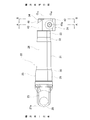
小径筒部33は、段付円筒形状を有し、筒部26の軸方向他端部に配置される。小径筒部33は、その軸方向他方側半部に、軸方向一方側に隣接する小径筒部33の軸方向一方側半部よりも小さい外径寸法を有する嵌合筒部34を備える。小径筒部33は、その外周面の軸方向中間部に、軸方向他方側を向いた略円輪状(C字状)の段差面35を有する。本例では、小径筒部33の軸方向他方側半部の外周面に、切削加工を施すことにより、嵌合筒部34および段差面35を形成している。嵌合筒部34は、円筒面状の外周面を有しており、小径筒部33の軸方向一方側半部に比べて、肉厚が小さい。嵌合筒部34の軸方向寸法は、クランプ24の軸方向寸法とほぼ同じである。段差面35は、クランプ24を嵌合筒部34に外嵌する際に、クランプ24の軸方向一端面を突き当てることで、シャフト23に対するクランプ24の軸方向に関する位置決めを図るために利用される。
The small-diameter cylindrical portion 33 has a stepped cylindrical shape and is arranged at the other axial end of the cylindrical portion 26. The small-diameter tubular portion 33 is provided with a fitting tubular portion 34 in the other half in the axial direction, the fitting tubular portion 34 having a smaller outer diameter dimension than the one half in the axial direction of the small-diameter tubular portion 33 adjacent to the one axial side. The small-diameter cylindrical portion 33 has a substantially circular ring-shaped (C-shaped) step surface 35 facing the other side in the axial direction at an axially intermediate portion of the outer peripheral surface thereof. In this example, the fitting cylindrical portion 34 and the step surface 35 are formed by cutting the outer peripheral surface of the other half of the small diameter cylindrical portion 33 in the axial direction. The fitting tubular portion 34 has a cylindrical outer peripheral surface, and has a smaller wall thickness than the half portion on one axial side of the small diameter tubular portion 33. The axial dimension of the fitting tubular portion 34 is substantially the same as the axial dimension of the clamp 24. The step surface 35 is used for positioning the clamp 24 in the axial direction with respect to the shaft 23 by abutting one axial end surface of the clamp 24 when the clamp 24 is fitted onto the fitting tubular portion 34. ..
本例では、筒部26の内周面のうち、軸方向他端部に相当する、小径筒部33および小径側円すい筒部32の内周面にのみ、雌セレーション36が全長にわたり設けられている。図1では、雌セレーションの図示を省略している。小径筒部33の内側には、図8に示すように、ステアリングシャフトやピニオン軸などの軸37の端部が挿入される。雌セレーション36は、軸37の外周面に形成された雄セレーション38とセレーション係合する。
In this example, the female serrations 36 are provided over the entire length only on the inner peripheral surfaces of the small diameter cylindrical portion 33 and the small diameter side conical cylindrical portion 32, which correspond to the other axial end of the inner peripheral surface of the cylindrical portion 26. There is. In FIG. 1, illustration of female serrations is omitted. As shown in FIG. 8, an end portion of a shaft 37 such as a steering shaft or a pinion shaft is inserted inside the small-diameter cylindrical portion 33. The female serration 36 is in serration engagement with a male serration 38 formed on the outer peripheral surface of the shaft 37.
シャフト23のうち、軸方向他端側部分(軸方向中間部から軸方向他端部)に相当する、中径筒部31から小径筒部33にわたる範囲に、軸方向に伸長するスリット39が設けられている。スリット39は、シャフト23の内周面と外周面とを連通しており、ヨーク部25を構成する1対の腕部27a、27bと円周方向に関する位相(周方向位置)が90度ずれた位置に配置される。スリット39の軸方向一方側は閉鎖端であり、小径筒部33よりも軸方向一方側に存在する中径筒部31の軸方向他端部に位置する。スリット39の軸方向他方側は開口端であり、シャフト23の嵌合筒部34の軸方向他端縁に開口する。本例では、スリット39の幅寸法は、全長にわたり一定である。スリット39は、カッターなどの回転切削工具を用いた切削加工により形成される。スリット39の軸方向一端部(奥端部)は、部分円弧状の断面形状を有する。スリット39は、軸方向一端部が閉鎖端であり、軸方向他端部が開口端であるため、クランプ24が外嵌される嵌合筒部34の剛性は、スリット39の開口端に近い軸方向他方側部分よりも、スリット39の閉鎖端に近い軸方向一方側部分の方が高い。
In the shaft 23, a slit 39 extending in the axial direction is provided in a range corresponding to the axially other end side portion (the axially intermediate portion to the axially other end portion), which extends from the medium diameter tubular portion 31 to the small diameter tubular portion 33. Has been. The slit 39 communicates the inner peripheral surface and the outer peripheral surface of the shaft 23, and the phase (circumferential position) with respect to the pair of arm portions 27a and 27b forming the yoke portion 25 in the circumferential direction is deviated by 90 degrees. Placed in position. One side in the axial direction of the slit 39 is a closed end, and is located at the other end portion in the axial direction of the medium-diameter tubular portion 31 that is located on one axial side of the small-diameter tubular portion 33. The other side in the axial direction of the slit 39 is an opening end, and opens at the other axial end of the fitting tubular portion 34 of the shaft 23. In this example, the width dimension of the slit 39 is constant over the entire length. The slits 39 are formed by cutting using a rotary cutting tool such as a cutter. One end (back end) in the axial direction of the slit 39 has a partial arc-shaped cross-sectional shape. Since one end of the slit 39 in the axial direction is a closed end and the other end of the axial direction is an open end, the rigidity of the fitting tubular portion 34 to which the clamp 24 is fitted is close to the axial end of the slit 39. The axial one side portion closer to the closed end of the slit 39 is higher than the axial other side portion.
シャフト23は、嵌合筒部34の軸方向中間部の外周面のうちで、スリット39と周方向の位相が一致する部分に、シャフト23の中心軸O23に対し直交する方向に伸長する係合凹溝40を備える。係合凹溝40は、スリット39と交差するように形成されている。係合凹溝40とスリット39との交差部は、スリット39のうちで交差部の軸方向両側に隣接する部分に比べて幅寸法が大きい幅広部からなる。係合凹溝40は、部分円筒面形状を有し、係合凹溝40の曲率半径はクランプ24の取付孔45a、45bの曲率半径とほぼ同じである。
The shaft 23 extends in a direction orthogonal to the central axis O 23 of the shaft 23 at a portion of the outer peripheral surface of the axially intermediate portion of the fitting tubular portion 34 where the phase in the circumferential direction matches the slit 39. The groove 40 is provided. The engagement groove 40 is formed so as to intersect with the slit 39. The intersection of the engaging groove 40 and the slit 39 is a wide portion having a width dimension larger than that of a portion of the slit 39 adjacent to both sides of the intersection in the axial direction. The engaging groove 40 has a partially cylindrical surface shape, and the radius of curvature of the engaging groove 40 is substantially the same as the radius of curvature of the mounting holes 45 a and 45 b of the clamp 24.
クランプ24は、シャフト23の軸方向他端部のうちの嵌合筒部34に外嵌固定されており、シャフト23の軸方向他端側部分、具体的には、スリット39が備えられた中径筒部31の軸方向他端部から嵌合筒部34にわたる範囲を縮径させるために用いられる。クランプ24は、シャフト23を構成する材料よりも硬度の高い、機械構造用炭素鋼であるS35Cなどの素材に熱間鍛造加工もしくは切削加工などを施すことにより、あるいは、機械構造用炭素鋼であるS10CやS15Cなどの素材に加工硬化を生じる冷間鍛造加工を施すことにより造られる。
The clamp 24 is externally fitted and fixed to the fitting cylinder portion 34 of the other axial end portion of the shaft 23, and is provided with a slit 39 on the other axial end portion of the shaft 23. It is used to reduce the diameter of the range from the other axial end of the diameter tubular portion 31 to the fitting tubular portion 34. The clamp 24 is a carbon steel for machine structure, which is obtained by subjecting a material such as S35C, which is carbon steel for machine structure, which is harder than the material forming the shaft 23, to hot forging or cutting. It is made by subjecting materials such as S10C and S15C to cold forging that causes work hardening.
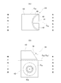
クランプ24は、全体として欠円筒形状(略U字状)を有し、不連続部41と、1対のフランジ部42と、連結部43と、挿入孔44とを備える。
The clamp 24 has an overall cylindrical shape (substantially U-shaped) as a whole, and includes a discontinuous portion 41, a pair of flange portions 42, a connecting portion 43, and an insertion hole 44.
不連続部41は、1対のフランジ部42の間に位置する、クランプ24の円周方向1箇所に配置される。1対のフランジ部42は、不連続部41を挟んで両側に配置される。1対のフランジ部42を構成するそれぞれのフランジ部は、略矩形板形状を有する。連結部43は、クランプ24の直径方向に関して不連続部41の反対側に配置され、1対のフランジ部42を構成するフランジ部を円周方向に連結する。挿入孔44は、連結部43の内周面と1対のフランジ部42の径方向内側面とにより構成される。挿入孔44には、シャフト23の嵌合筒部34が挿入される。挿入孔44は、部分円筒面状で、その内径寸法は、クランプ24の自由状態で、嵌合筒部34の自由状態での外径寸法と同じかこれよりも僅かに大きい。
The discontinuous portion 41 is located at one position in the circumferential direction of the clamp 24, which is located between the pair of flange portions 42. The pair of flange portions 42 are arranged on both sides of the discontinuous portion 41. Each of the flange portions forming the pair of flange portions 42 has a substantially rectangular plate shape. The connecting portion 43 is arranged on the opposite side of the discontinuous portion 41 in the diametrical direction of the clamp 24, and connects the flange portions forming the pair of flange portions 42 in the circumferential direction. The insertion hole 44 is composed of the inner peripheral surface of the connecting portion 43 and the radially inner surface of the pair of flange portions 42. The fitting cylinder portion 34 of the shaft 23 is inserted into the insertion hole 44. The insertion hole 44 has a partially cylindrical surface shape, and the inner diameter dimension thereof is equal to or slightly larger than the outer diameter dimension of the fitting tubular portion 34 in the free state of the clamp 24.
クランプ24をシャフト23の嵌合筒部34に固定した状態で、不連続部41とスリット39の周方向位置は、互いに一致する。本例では、クランプ24の自由状態での不連続部41の幅寸法と、シャフト23(嵌合筒部34)の自由状態でのスリット39の幅寸法は、互いにほぼ同じである。
With the clamp 24 fixed to the fitting cylinder portion 34 of the shaft 23, the positions of the discontinuous portion 41 and the slit 39 in the circumferential direction coincide with each other. In this example, the width dimension of the discontinuous portion 41 in the free state of the clamp 24 and the width dimension of the slit 39 in the free state of the shaft 23 (fitting cylinder portion 34) are substantially the same.
1対のフランジ部42を構成するフランジ部の互いに整合する部分に、板厚方向に貫通し、互いに同軸である取付孔45a、45bが備えられる。取付孔45a、45bは、挿入孔44の中心軸O44に対し捩れの位置に形成されており、挿入孔44に開口する。取付孔45a、45bのうちの一方の取付孔45aは通孔により構成され、他方の取付孔45bはねじ孔により構成される。クランプ24をシャフト23の嵌合筒部34に固定した状態で、取付孔45a、45bの開口部に対向する位置に、係合凹溝40が位置する。すなわち、取付孔45a、45bと係合凹溝40との軸方向位置は一致する。また、1対のフランジ部42を構成するフランジ部の板厚(厚さ寸法)は、互いにほぼ同じである。
Mounting holes 45a and 45b that are coaxial with each other are provided in portions of the flange portions that configure the pair of flange portions 42 that are aligned with each other, and that penetrate in the plate thickness direction. The mounting holes 45 a and 45 b are formed at positions twisted with respect to the central axis O 44 of the insertion hole 44 and open in the insertion hole 44. One of the mounting holes 45a and 45b is a through hole, and the other mounting hole 45b is a screw hole. With the clamp 24 fixed to the fitting cylinder portion 34 of the shaft 23, the engagement groove 40 is located at a position facing the openings of the mounting holes 45a and 45b. That is, the axial positions of the mounting holes 45a and 45b and the engaging groove 40 are aligned. The plate thicknesses (thicknesses) of the flange portions forming the pair of flange portions 42 are substantially the same.
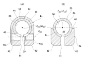
連結部43は、半円筒形状を有し、その軸方向他方側部分に、フランジ部42の軸方向他端面から軸方向一方側に凹んだ切り欠き46を備える。切り欠き46は、連結部43の円周方向に伸長し、シャフト23の中心軸O23および挿入孔44の中心軸O44を含み、かつ、取付孔45a、45bの中心軸O45に直交する仮想平面に関して対称形状を有する。切り欠き46の形状は、図7(B)に示すように、取付孔45a、45bの軸方向から見た場合に、略三角形状である。このため、切り欠き46の切り欠き深さに相当する軸方向幅Lは、連結部43の円周方向に関してフランジ部42から離れるほど(図7(B)の上側に向かうほど)大きくなり、直径方向に関して不連続部41の反対側に位置する部分(図7(B)の上端部)で最も大きくなる。すなわち、切り欠き46の軸方向幅Lは、連結部43の円周方向両端部で最も小さくなり、連結部43の円周方向中央部で最も大きくなる。
The connecting portion 43 has a semi-cylindrical shape, and is provided with a notch 46 that is recessed from the other end surface in the axial direction of the flange portion 42 to the one side in the axial direction, in the portion on the other side in the axial direction. Notch 46 extending in the circumferential direction of the connecting portion 43 includes a central axis O 44 of the center axis O 23 and the insertion hole 44 of the shaft 23 and perpendicular to the mounting holes 45a, 45b center axis O 45 of It has a symmetrical shape with respect to the virtual plane. As shown in FIG. 7B, the notch 46 has a substantially triangular shape when viewed in the axial direction of the mounting holes 45a and 45b. For this reason, the axial width L corresponding to the notch depth of the notch 46 becomes larger as it goes away from the flange portion 42 in the circumferential direction of the connecting portion 43 (as it goes to the upper side in FIG. 7B), and the diameter becomes larger. It becomes the largest in the portion (upper end portion in FIG. 7B) located on the opposite side of the discontinuous portion 41 in the direction. That is, the axial width L of the notch 46 is smallest at both circumferential ends of the connecting portion 43, and is largest at the circumferential central portion of the connecting portion 43.
切り欠き46は、取付孔45a、45bの中心軸O45よりも軸方向他方側に配置される。具体的には、切り欠き46の軸方向一端縁は、取付孔45a、45bの中心軸O45よりも軸方向他方側で、かつ、取付孔45a、45bの軸方向他端縁よりも軸方向一方側に位置する。連結部43の円周方向に関する切り欠き46の端部(連結部43と切り欠き46との円周方向に関する境界位置)は、連結部43の軸方向他端縁において、取付孔45a、45bの中心軸O45およびシャフト23の中心軸O23にそれぞれ直交する方向(図2および図7(B)の上下方向)に関して、シャフト23の中心軸O23よりも取付孔45a、45bに近い側(図2および図7(B)の下側)に位置する。
The notch 46 is arranged on the other side in the axial direction with respect to the central axis O 45 of the mounting holes 45a and 45b. Specifically, one end of the notch 46 in the axial direction is on the other side in the axial direction than the central axis O 45 of the mounting holes 45a and 45b, and is more axial than the other end of the mounting holes 45a and 45b in the axial direction. Located on one side. The end of the notch 46 in the circumferential direction of the connecting portion 43 (the boundary position in the circumferential direction between the connecting portion 43 and the notch 46) is provided at the other end of the connecting portion 43 in the axial direction with respect to the mounting holes 45a, 45b. Regarding the directions orthogonal to the central axis O 45 and the central axis O 23 of the shaft 23 (vertical direction in FIGS. 2 and 7B), the sides closer to the mounting holes 45a and 45b than the central axis O 23 of the shaft 23 ( 2 and FIG. 7 (B) (lower side).
連結部43は、切り欠き46を形成する以前の状態では、1対のフランジ部42と同じ軸方向幅を全周にわたり有していたが、切り欠き46を形成することで、1対のフランジ部42に接続する円周方向両端部では、1対のフランジ部42と同じ軸方向幅を有しているが、円周方向に関して1対のフランジ部42から離れるほど軸方向幅が小さくなり、直径方向に関して不連続部41の反対側に位置する円周方向中央部では、その軸方向幅は1対のフランジ部42の軸方向幅のおよそ3/5程度である。このため、連結部43の形状は、取付孔45a、45bの軸方向から見た場合に、軸方向他方側の肩部(角部)が斜めに切り落とされたような台形状である。連結部43の軸方向他端面(連結部43と切り欠き46との軸方向に関する境界位置)は、連結部43の円周方向に関して1対のフランジ部42から離れるほど軸方向一方側に向かう方向に直線的に傾斜する。すなわち、連結部43の軸方向他端面は、連結部43の軸方向一端面のように、挿入孔44の中心軸O44に直交する仮想平面上には存在せず、挿入孔44の中心軸O44に対して傾斜する。図示の例では、挿入孔44の中心軸O44に対する連結部43の軸方向他端面の傾斜角度は60度である。本例では、嵌合筒部34の軸方向他方側部分のうち、直径方向に関してスリット39の反対側に位置する部分が、クランプ24の連結部43によって覆われずに、切り欠き46から外部に露出する。
In the state before forming the notch 46, the connecting portion 43 had the same axial width as the pair of flange portions 42 over the entire circumference, but by forming the notch 46, the pair of flanges 42 is formed. Both ends in the circumferential direction connected to the portions 42 have the same axial width as the pair of flange portions 42, but the axial width becomes smaller as the distance from the pair of flange portions 42 in the circumferential direction increases, At the central portion in the circumferential direction located on the opposite side of the discontinuous portion 41 in the diametrical direction, the axial width thereof is approximately 3/5 of the axial width of the pair of flange portions 42. Therefore, the shape of the connecting portion 43 is a trapezoidal shape in which the shoulder portion (corner portion) on the other axial side is cut off obliquely when viewed in the axial direction of the mounting holes 45a and 45b. The other axial end surface of the connecting portion 43 (the boundary position in the axial direction between the connecting portion 43 and the notch 46) is directed toward the one axial side as the distance from the pair of flange portions 42 in the circumferential direction of the connecting portion 43 increases. Slopes linearly to. That is, the other axial end surface of the connecting portion 43 does not exist on an imaginary plane orthogonal to the central axis O 44 of the insertion hole 44 like the axial one end surface of the connecting portion 43, and the central axis of the inserting hole 44 does not exist. Inclined with respect to O 44 . In the illustrated example, the inclination angle of the other axial end surface of the connecting portion 43 with respect to the central axis O 44 of the insertion hole 44 is 60 degrees. In the present example, of the other axial side portion of the fitting tubular portion 34, the portion located on the opposite side of the slit 39 in the diametrical direction is not covered by the connecting portion 43 of the clamp 24, and is exposed to the outside from the notch 46. Exposed.
本例では、シャフト23とクランプ24とは結合固定されている。シャフト23とクランプ24との結合固定の構造は特に限定されないが、例えば、シャフト23とクランプ24とを溶接固定した構造を採用することができる。あるいは、シャフト23の外周面に形成した凸状(または凹状)のシャフト側係合部と、クランプ24の内周面に形成した凹状(または凸状)のクランプ側係合部とを凹凸係合させるとともに、シャフト側係合部またはクランプ側係合部を塑性変形させた(かしめた)構造なども採用することができる。いずれの場合でも、シャフト23とクランプ24とを固定した状態では、シャフト23とクランプ24との相対回転および軸方向に関する相対変位が防止される。
In this example, the shaft 23 and the clamp 24 are fixed together. The structure for connecting and fixing the shaft 23 and the clamp 24 is not particularly limited, but, for example, a structure in which the shaft 23 and the clamp 24 are fixed by welding can be adopted. Alternatively, the convex (or concave) shaft-side engaging portion formed on the outer peripheral surface of the shaft 23 and the concave (or convex) clamp-side engaging portion formed on the inner peripheral surface of the clamp 24 are engaged and recessed. In addition to this, a structure in which the shaft side engaging portion or the clamp side engaging portion is plastically deformed (caulked) or the like can also be adopted. In any case, when the shaft 23 and the clamp 24 are fixed, relative rotation between the shaft 23 and the clamp 24 and relative displacement in the axial direction are prevented.
シャフト23とクランプ24とを結合固定する際には、まず、クランプ24の挿入孔44の内側に、シャフト23の軸方向他端部を、クランプ24の軸方向一方側から挿入する。クランプ24の不連続部41とシャフト23のスリット39との周方向位置を一致させるとともに、取付孔45a、45bと係合凹溝40との軸方向位置を一致させる。本例では、クランプ24の軸方向一端面を段差面35に突き当てることで、取付孔45a、45bと係合凹溝40との軸方向位置が一致するように、各部の寸法が規制されている。
When connecting and fixing the shaft 23 and the clamp 24, first, the other axial end of the shaft 23 is inserted into the insertion hole 44 of the clamp 24 from one axial side of the clamp 24. The circumferential position of the discontinuous portion 41 of the clamp 24 and the slit 39 of the shaft 23 are matched, and the axial positions of the mounting holes 45a and 45b and the engaging groove 40 are matched. In the present example, the dimension of each portion is regulated by abutting the one axial end surface of the clamp 24 against the step surface 35 so that the axial positions of the mounting holes 45a and 45b and the engaging groove 40 coincide with each other. There is.
次に、取付孔45a、45bと係合凹溝40の内側に、締付部材に相当する締付ボルト47を配置する。具体的には、締付ボルト47の基端寄り部分を通孔である一方の取付孔45aの内側に挿入するとともに、締付ボルト47の中間部を係合凹溝40の内側に配置する。この状態で、締付ボルト47の先端部を、ねじ孔である他方の取付孔45bに少しだけ、すなわち、嵌合筒部34を縮径させない程度に螺合する。そして、係合凹溝40と、クランプ24に対して両端部が支持された締付ボルト47とを、キー係合させる。これにより、クランプ24がシャフト23から軸方向他方側に抜け出ないようにするとともに、シャフト23とクランプ24とが相対回転しないようにする。そして最後に、溶接などの固定手段により、シャフト23とクランプ24とを結合固定する。
Next, a tightening bolt 47 corresponding to a tightening member is arranged inside the mounting holes 45a and 45b and the engaging groove 40. Specifically, the portion of the tightening bolt 47 near the base end is inserted into one of the mounting holes 45a, which is a through hole, and the intermediate portion of the tightening bolt 47 is arranged inside the engaging groove 40. In this state, the tip end of the tightening bolt 47 is screwed into the other mounting hole 45b, which is a screw hole, only slightly, that is, to the extent that the fitting tubular portion 34 is not reduced in diameter. Then, the engagement groove 40 and the tightening bolt 47 whose both ends are supported by the clamp 24 are key-engaged. This prevents the clamp 24 from coming out of the shaft 23 to the other side in the axial direction, and prevents the shaft 23 and the clamp 24 from rotating relative to each other. And finally, the shaft 23 and the clamp 24 are coupled and fixed by a fixing means such as welding.
本例では、トルク伝達軸22の使用状態では、トルク伝達軸22の軸方向一端部に配置されたヨーク部25は、図示しない別のヨークおよび十字軸と組み合わされる。これにより、トルク伝達軸22は、前記別のヨークを備えた中間シャフトなどの軸にトルク伝達可能に接続される。ただし、本発明を実施する場合に、トルク伝達軸の軸方向一端部に配置される接続部は、自在継手を構成するヨーク部に代替して、該接続部に軸などの他の部材を接続可能な、セレーション部、スプライン部、あるいは、キー係合部により構成されることも可能である。
In this example, when the torque transmission shaft 22 is in use, the yoke portion 25 arranged at one axial end portion of the torque transmission shaft 22 is combined with another yoke and a cross shaft, not shown. As a result, the torque transmission shaft 22 is connected to the shaft such as the intermediate shaft having the other yoke so as to be able to transmit the torque. However, when carrying out the present invention, the connecting portion arranged at one axial end of the torque transmission shaft is replaced with a yoke portion forming a universal joint, and other members such as a shaft are connected to the connecting portion. It is also possible to use a serration part, a spline part, or a key engaging part.
小径筒部33の内側に、ステアリングシャフトやピニオン軸などの軸37が挿入され、軸37の外周面の雄セレーション38に、小径筒部33の内周面の雌セレーション36がセレーション係合する。これにより、トルク伝達軸22と軸37との相対回転が防止される。軸37の先端部外周面に雄セレーション38を周方向に横切るように形成された周方向凹溝48の内側に、係合凹溝40とスリット39との交差部である幅広部を通じて締付ボルト47の中間部が進入し、周方向凹溝48と締付ボルト47とがキー係合する。これにより、軸37とトルク伝達軸22との軸方向の相対移動が防止される。締付ボルト47の他方の取付孔45bに対する螺合量の増加に伴って、不連続部41の幅寸法が小さくなり、小径筒部33が縮径して、小径筒部33の内周面により軸37の外周面が強く締め付けられる。これにより、トルク伝達軸22と軸37とがトルク伝達可能に結合する。
A shaft 37 such as a steering shaft or a pinion shaft is inserted inside the small-diameter cylindrical portion 33, and a male serration 38 on the outer peripheral surface of the shaft 37 is serrated with a female serration 36 on the inner peripheral surface of the small-diameter cylindrical portion 33. As a result, relative rotation between the torque transmission shaft 22 and the shaft 37 is prevented. Inside the circumferential groove 48 formed on the outer peripheral surface of the tip portion of the shaft 37 so as to traverse the male serration 38 in the circumferential direction, a tightening bolt is passed through a wide portion which is an intersection of the engaging groove 40 and the slit 39. The intermediate portion of 47 enters, and the circumferential groove 48 and the tightening bolt 47 are key-engaged. As a result, relative movement of the shaft 37 and the torque transmission shaft 22 in the axial direction is prevented. As the amount of screwing of the tightening bolt 47 into the other mounting hole 45b increases, the width dimension of the discontinuous portion 41 decreases, the small-diameter cylindrical portion 33 contracts, and the inner peripheral surface of the small-diameter cylindrical portion 33 reduces the diameter. The outer peripheral surface of the shaft 37 is strongly tightened. As a result, the torque transmission shaft 22 and the shaft 37 are coupled so that torque can be transmitted.
本例のトルク伝達軸22では、トルク伝達軸22に接続される軸の振れ回り抑止される。すなわち、本例のトルク伝達軸22では、クランプはシャフトに対して一体に設けられておらず、別体のクランプ24がシャフト23に対して固定されている。このため、シャフト23の軸方向両端部に配置されるヨーク部25と雌セレーション36との同軸度が、高く確保される。また、本例のトルク伝達軸22では、別体のヨーク部をシャフトに固定するのではなく、シャフト23とヨーク部25は一体に設けられている。このため、溶接時の熱変形の影響を受けずに済み、シャフト23(筒部26)に対するヨーク部25の同軸度が、高く確保される。したがって、ヨーク部25に接続される軸および雌セレーション36に接続される軸37の振れ回りが効果的に抑止される。この結果、ステアリング装置の一部で、軸の振れ回りに起因した、回転方向の摺動異音、スティックスリップ振動異音などの異音の発生が防止される。また、本例のシャフト23は、中空状であるため、トルク伝達軸22全体としての軽量化が図られる。
In the torque transmission shaft 22 of this example, whirling of the shaft connected to the torque transmission shaft 22 is suppressed. That is, in the torque transmission shaft 22 of this example, the clamp is not provided integrally with the shaft, but the separate clamp 24 is fixed to the shaft 23. For this reason, a high degree of coaxiality between the yoke portion 25 and the female serrations 36 arranged at both axial ends of the shaft 23 is ensured. Further, in the torque transmission shaft 22 of the present example, the separate yoke portion is not fixed to the shaft, but the shaft 23 and the yoke portion 25 are integrally provided. Therefore, it is not affected by thermal deformation during welding, and the coaxiality of the yoke portion 25 with respect to the shaft 23 (cylindrical portion 26) is ensured to be high. Therefore, whirling of the shaft connected to the yoke portion 25 and the shaft 37 connected to the female serration 36 is effectively suppressed. As a result, in a part of the steering device, it is possible to prevent abnormal noise such as sliding abnormal noise in the rotation direction and stick-slip vibration abnormal noise due to whirling of the shaft. Further, since the shaft 23 of this example is hollow, the weight of the torque transmission shaft 22 as a whole can be reduced.
本例のトルク伝達軸22では、シャフト23の軸方向他端部に接続された軸37の歳差運動が抑止され、この軸37の歳差運動に起因する、シャフト23の雌セレーション36と軸37の雄セレーション38とのセレーション係合部におけるフレッチング摩耗の発生が抑制される。すなわち、シャフト23に備えられたスリット39のうち、軸方向一方側が閉鎖端であり、軸方向他方側が開口端であるため、クランプ24が外嵌される嵌合筒部34の剛性は、スリット39の開口端に近い軸方向他方側部分よりも、スリット39の閉鎖端に近い軸方向一方側部分の方が高い。さらに、小径筒部33のうちで、嵌合筒部34よりも軸方向一方側に存在する部分の肉厚は、嵌合筒部34の肉厚よりも大きいため、この面からも、嵌合筒部34は、軸方向他方側部分の剛性よりも軸方向一方側部分の剛性の方が高くなる。このため、本例とは異なって、連結部に切り欠きが備えられていないクランプを用いて嵌合筒部34を縮径した場合、嵌合筒部34は、軸方向一方側部分よりも軸方向他方側部分の方が大きく変形する傾向になる。したがって、嵌合筒部34の内周面と軸37の外周面との間の面圧は、軸方向一方側部分(軸37の先端側部分)よりも軸方向他方側部分(軸37の基端側部分)の方が高くなる。すなわち、軸37は、嵌合筒部34の軸方向他方側部分で強く締め付けられ、それよりも軸方向一方側に位置する部分では比較的緩く締め付けられた状態になる。このため、軸37は、嵌合筒部34の軸方向他方側部分によって強く締め付けられた部分を中心に歳差運動しやすくなる。軸37の歳差運動が生じると、雌セレーション36と雄セレーション38とのセレーション係合部にフレッチング摩耗が発生し、摩耗量が過大になりやすくなる。
In the torque transmission shaft 22 of this example, the precession movement of the shaft 37 connected to the other axial end of the shaft 23 is suppressed, and the precession movement of the shaft 37 causes the female serration 36 of the shaft 23 and the shaft. The occurrence of fretting wear at the serration engaging portion of the male serration 38 of 37 is suppressed. That is, of the slits 39 provided in the shaft 23, one side in the axial direction is the closed end and the other side in the axial direction is the open end, so the rigidity of the fitting tubular portion 34 to which the clamp 24 is fitted is determined by the slit 39. The axial one side portion near the closed end of the slit 39 is higher than the axial other side portion near the open end. Further, the wall thickness of the portion of the small-diameter tubular portion 33 that is located on the one axial side of the fitting tubular portion 34 is larger than the wall thickness of the fitting tubular portion 34. In the tubular portion 34, the rigidity of one axial side portion is higher than the rigidity of the other axial side portion. Therefore, unlike the present example, when the diameter of the fitting tubular portion 34 is reduced by using a clamp having no notch in the connecting portion, the fitting tubular portion 34 is more axial than the axial one side portion. The part on the other side in the direction tends to be deformed more. Therefore, the surface pressure between the inner peripheral surface of the fitting tubular portion 34 and the outer peripheral surface of the shaft 37 is greater than the axially one side portion (the tip side portion of the shaft 37) of the other axial side portion (the base of the shaft 37). The edge part) is higher. That is, the shaft 37 is strongly tightened at the other axial side portion of the fitting tubular portion 34, and is relatively loosely tightened at the axially one side portion thereof. Therefore, the shaft 37 easily precesses around the portion that is strongly tightened by the axially other side portion of the fitting tubular portion 34. When the precession movement of the shaft 37 occurs, fretting wear occurs at the serration engagement portion between the female serration 36 and the male serration 38, and the amount of wear tends to become excessive.
本例では、連結部43の軸方向他側部分に切り欠き46が設けられており、剛性の低い嵌合筒部34の軸方向他方側部分は、連結部43により覆われない。このため、クランプ24により嵌合筒部34を縮径した際に、嵌合筒部34のうちで、剛性の高い軸方向一方側部分に、剛性の低い軸方向他方側部分に比べて大きな締付け力が付与される。嵌合筒部34に生じる変形量を、軸方向一方側部分と軸方向他方側部分とで互いに近づけることができる。嵌合筒部34の内周面と軸37の外周面との間の面圧も、軸方向一方側部分と軸方向他方側部分とで互いに近づけることができる。この結果、シャフト23の軸方向他端部に接続された軸37に歳差運動が生じることが抑制され、雌セレーション36と雄セレーション38とのセレーション係合部に、フレッチング摩耗が生じることが抑制される。これにより、シャフト23と軸37との間にがたつきが生じることが防止され、がたつきに起因した異音の発生が防止される。
In this example, the notch 46 is provided in the axially other side portion of the coupling portion 43, and the axially other side portion of the fitting cylinder portion 34 having low rigidity is not covered by the coupling portion 43. For this reason, when the diameter of the fitting tubular portion 34 is reduced by the clamp 24, the fitting tubular portion 34 is tightened to one portion in the axial direction having high rigidity, which is larger than that in the other axial portion having low rigidity. Power is given. The amount of deformation generated in the fitting tubular portion 34 can be made closer to each other in the axially one side portion and the axially other side portion. The surface pressure between the inner peripheral surface of the fitting tubular portion 34 and the outer peripheral surface of the shaft 37 can also be close to each other in the axially one side portion and the axially other side portion. As a result, precession of the shaft 37 connected to the other axial end of the shaft 23 is suppressed, and fretting wear is suppressed at the serration engaging portions of the female serration 36 and the male serration 38. To be done. This prevents rattling between the shaft 23 and the shaft 37, and prevents generation of abnormal noise due to rattling.
切り欠き46は、取付孔45a、45bの中心軸よりも軸方向他方側に配置されるため、クランプ24により嵌合筒部34を縮径した際に、連結部43によって、剛性の高い嵌合筒部34の軸方向一方側部分に大きな締付け力を付与することができる。このため、嵌合筒部34の軸方向一方側部分の内周面と軸37の外周面との間の面圧を効果的に高めることができる。さらに、連結部43の円周方向に関する切り欠き46の端部は、連結部43の軸方向他端縁において、取付孔45a、45bの中心軸O45およびシャフト23の中心軸O23にそれぞれ直交する方向に関して、シャフト23の中心軸O23よりも取付孔45a、45bに近い側に位置する。このため、図3(B)に示すように、シャフト23の軸方向他端縁は、直径方向に関してスリット39の反対側に位置する半円弧状部分が、外部に露出した状態になり、連結部43によって覆われない。したがって、クランプ24により嵌合筒部34を縮径した際に、シャフト23の軸方向他端縁に加わる締付け力を十分に小さくできる。したがって、シャフト23の軸方向他端部に連結される軸37に歳差運動が生じることがより有効に防止される。また、切り欠き46は、連結部43にのみ配置され、フランジ部42には配置されていないため、シャフト23に対するクランプ24の軸方向に関する嵌合長が十分に確保される。このため、シャフト23に対するクランプ24の姿勢を安定させることができる。
Since the notch 46 is arranged on the other side in the axial direction with respect to the central axes of the mounting holes 45a and 45b, when the fitting tubular portion 34 is reduced in diameter by the clamp 24, the fitting portion with high rigidity is provided by the connecting portion 43. A large tightening force can be applied to the axially one side portion of the tubular portion 34. Therefore, it is possible to effectively increase the surface pressure between the inner peripheral surface of the one axial side portion of the fitting tubular portion 34 and the outer peripheral surface of the shaft 37. Further, the end portion of the notch 46 in the circumferential direction of the connecting portion 43, in the other axial end edge of the connecting portion 43, respectively to the central axis O 23 of the mounting hole 45a, 45b of the central axis O 45 and the shaft 23 perpendicular with respect to the direction of mounting holes 45a of the center axis O 23 of the shaft 23, located closer to 45b. Therefore, as shown in FIG. 3B, at the other end of the shaft 23 in the axial direction, the semi-arcuate portion located on the opposite side of the slit 39 in the diametrical direction is exposed to the outside, and the connecting portion is formed. Not covered by 43. Therefore, when the diameter of the fitting cylinder portion 34 is reduced by the clamp 24, the tightening force applied to the other axial end of the shaft 23 can be sufficiently reduced. Therefore, precession of the shaft 37 connected to the other end of the shaft 23 in the axial direction is more effectively prevented. Further, since the notch 46 is arranged only in the connecting portion 43 and not in the flange portion 42, a sufficient fitting length in the axial direction of the clamp 24 with respect to the shaft 23 is secured. Therefore, the posture of the clamp 24 with respect to the shaft 23 can be stabilized.
[第2例]
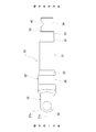
本発明の実施の形態の第2例について、図9~図10を用いて説明する。本例では、シャフト23の嵌合筒部34に外嵌されるクランプ24aの形状が、第1例の構造と異なっている。具体的には、本例では、クランプ24aを構成する連結部43aの軸方向他方側部分(半部)に設けられた切り欠き46aの形状が、第1例の切り欠き46の形状と異なっている。切り欠き46aの形状は、取付孔45a、45bの軸方向から見た場合に、略矩形状である。切り欠き46aの軸方向幅Lは、連結部43aの円周方向に関して一定である。このため、連結部43aの形状は、取付孔45a、45bの軸方向から見た場合に、軸方向他方側半部が切り落とされたような略矩形状である。連結部43aの軸方向他端面(連結部43aと切り欠き46aとの軸方向に関する境界位置)は、連結部43aの軸方向一端面と平行で、挿入孔44の中心軸O44に直交する仮想平面上に存在する。 [Second example]
A second example of the embodiment of the present invention will be described with reference to FIGS. 9 to 10. In this example, the shape of theclamp 24a that is fitted onto the fitting cylinder portion 34 of the shaft 23 is different from that of the structure of the first example. Specifically, in this example, the shape of the notch 46a provided in the axially other side portion (half portion) of the connecting portion 43a that constitutes the clamp 24a is different from the shape of the notch 46 of the first example. There is. The notch 46a has a substantially rectangular shape when viewed in the axial direction of the mounting holes 45a and 45b. The axial width L of the notch 46a is constant in the circumferential direction of the connecting portion 43a. Therefore, the connecting portion 43a has a substantially rectangular shape in which the other half in the axial direction is cut off when viewed from the axial direction of the mounting holes 45a and 45b. The other end surface in the axial direction of the connecting portion 43a (the boundary position in the axial direction between the connecting portion 43a and the notch 46a) is parallel to the one end surface in the axial direction of the connecting portion 43a and is orthogonal to the central axis O 44 of the insertion hole 44. Exists on a plane.
本発明の実施の形態の第2例について、図9~図10を用いて説明する。本例では、シャフト23の嵌合筒部34に外嵌されるクランプ24aの形状が、第1例の構造と異なっている。具体的には、本例では、クランプ24aを構成する連結部43aの軸方向他方側部分(半部)に設けられた切り欠き46aの形状が、第1例の切り欠き46の形状と異なっている。切り欠き46aの形状は、取付孔45a、45bの軸方向から見た場合に、略矩形状である。切り欠き46aの軸方向幅Lは、連結部43aの円周方向に関して一定である。このため、連結部43aの形状は、取付孔45a、45bの軸方向から見た場合に、軸方向他方側半部が切り落とされたような略矩形状である。連結部43aの軸方向他端面(連結部43aと切り欠き46aとの軸方向に関する境界位置)は、連結部43aの軸方向一端面と平行で、挿入孔44の中心軸O44に直交する仮想平面上に存在する。 [Second example]
A second example of the embodiment of the present invention will be described with reference to FIGS. 9 to 10. In this example, the shape of the
切り欠き46aは、取付孔45a、45bの中心軸45よりも軸方向他方側(図9および図10の右側)に位置する。具体的には、切り欠き46aの軸方向一端縁は、取付孔45a、45bの軸方向他端縁とほぼ同じ軸方向位置に存在する。また、連結部43aの円周方向に関する切り欠き46aの端部(連結部43aと切り欠き46aとの円周方向に関する境界位置)は、シャフト23の中心軸O23と平行に配置されており、取付孔45a、45bの中心軸O45およびシャフト23の中心軸O23にそれぞれ直交する方向(図9および図10の上下方向)に関して、シャフト23の中心軸O23よりも取付孔45a、45bに近い側(図9および図10の下側)に位置する。本例では、嵌合筒部34の軸方向他方側部分のうちで、直径方向に関してスリット39の反対側に位置する部分が、第1例の場合よりも広い範囲にわたって、切り欠き46aから外部に露出する。
The notch 46a is located on the other axial side (the right side in FIGS. 9 and 10) with respect to the central axis 45 of the mounting holes 45a and 45b. Specifically, one end of the notch 46a in the axial direction is located at substantially the same axial position as the other end of the mounting holes 45a and 45b in the axial direction. The end portion of the cutout 46a in the circumferential direction of the connecting portion 43a (circumferential about the boundary position between the connecting portion 43a and the notch 46a) is arranged parallel to the central axis O 23 of the shaft 23, Regarding the directions (vertical direction in FIGS. 9 and 10) orthogonal to the central axis O 45 of the mounting holes 45 a and 45 b and the central axis O 23 of the shaft 23 , respectively, the mounting holes 45 a and 45 b are located farther than the central axis O 23 of the shaft 23. Located on the near side (lower side of FIGS. 9 and 10). In this example, in the axially other side portion of the fitting tubular portion 34, the portion located on the opposite side of the slit 39 in the diametrical direction extends outward from the notch 46a over a wider range than in the first example. Exposed.
本例では、切り欠き46aの形成範囲が、第1例に比べて大きいため、クランプ24aから、嵌合筒部34のうちで剛性の低い軸方向他方側部分に作用する締付け力をより小さくすることができる。その他の構成および作用効果については、第1例と同じである。
In this example, since the range in which the notch 46a is formed is larger than that in the first example, the tightening force that acts from the clamp 24a to the other axially low-side portion of the fitting tubular portion 34 that is less rigid is further reduced. be able to. Other configurations and operational effects are the same as in the first example.
本発明を実施する場合に、クランプの連結部に形成する切り欠きの形状およびその形成範囲は、本発明の実施の形態の各例で示した構造に限定されることはない。連結部の円周方向に関する切り欠きの端部を、取付孔の中心軸およびシャフトの中心軸にそれぞれ直交する方向に関して、シャフトの中心軸を挟んで取付孔と反対側に配置させることもできるし、シャフトの中心軸上に配置させることもできる。また、クランプの取付孔をすべて通孔により構成し、締付ボルトとナットを組み合わせて使用することもできる。さらに、本発明の実施の形態の各例の構造は、矛盾が生じない限りにおいて、適宜組み合わせて実施することができる。
When the present invention is carried out, the shape and the range of the notch formed in the connecting portion of the clamp are not limited to the structure shown in each example of the embodiment of the present invention. The end portion of the notch in the circumferential direction of the connecting portion may be arranged on the opposite side of the mounting hole with the central axis of the shaft interposed therebetween in the directions orthogonal to the central axis of the mounting hole and the central axis of the shaft. , Can also be arranged on the central axis of the shaft. Alternatively, the clamp mounting holes may be all through holes, and the tightening bolts and nuts may be used in combination. Furthermore, the structures of the respective examples of the embodiments of the present invention can be appropriately combined and implemented as long as no contradiction occurs.
1 ステアリングホイール
2 ステアリングシャフト
3 ステアリングコラム
4a、4b 自在継手
5 中間シャフト
6 ステアリングギヤユニット
7 タイロッド
8 ピニオン軸
9 トルク伝達軸
10 ヨーク
11、11a 軸
12 雄セレーション
13 雌セレーション
14 クランプ部
15 不連続部
16 フランジ部
17 取付孔
18 基部
19 雌セレーション
20 溶接ビード部
21 雄セレーション
22 トルク伝達軸
23 シャフト
24、24a クランプ
25 ヨーク部
26 筒部
27a、27b 腕部
28 円孔
29 大径筒部
30 大径側円すい筒部
31 中径筒部
32 小径側円すい筒部
33 小径筒部
34 嵌合筒部
35 段差面
36 雌セレーション
37 軸
38 雄セレーション
39 スリット
40 係合凹溝
41 不連続部
42 フランジ部
43、43a 連結部
44 挿入孔
45a、45b 取付孔
46、46a 切り欠き
47 締付ボルト
48 周方向凹溝 1Steering Wheel 2 Steering Shaft 3 Steering Column 4a, 4b Universal Joint 5 Intermediate Shaft 6 Steering Gear Unit 7 Tie Rod 8 Pinion Shaft 9 Torque Transmission Shaft 10 Yoke 11, 11a Shaft 12 Male Serration 13 Female Serration 14 Clamp 15 Discontinuity 16 Flange 17 Mounting hole 18 Base 19 Female serration 20 Weld bead 21 Male serration 22 Torque transmission shaft 23 Shaft 24, 24a Clamp 25 Yoke 26 Cylinder 27a, 27b Arm 28 Circular hole 29 Large diameter cylinder 30 Large diameter side Conical cylindrical portion 31 Medium diameter cylindrical portion 32 Small diameter side conical cylindrical portion 33 Small diameter cylindrical portion 34 Fitting cylindrical portion 35 Step surface 36 Female serration 37 Shaft 38 Male serration 39 Slit 40 Engagement groove 41 Discontinuous portion 42 Flange portion 43, 43a Connection part 44 Insertion hole 45a, 45b Mounting hole 46, 46a Notch 47 Tightening bolt 48 Circumferential groove
2 ステアリングシャフト
3 ステアリングコラム
4a、4b 自在継手
5 中間シャフト
6 ステアリングギヤユニット
7 タイロッド
8 ピニオン軸
9 トルク伝達軸
10 ヨーク
11、11a 軸
12 雄セレーション
13 雌セレーション
14 クランプ部
15 不連続部
16 フランジ部
17 取付孔
18 基部
19 雌セレーション
20 溶接ビード部
21 雄セレーション
22 トルク伝達軸
23 シャフト
24、24a クランプ
25 ヨーク部
26 筒部
27a、27b 腕部
28 円孔
29 大径筒部
30 大径側円すい筒部
31 中径筒部
32 小径側円すい筒部
33 小径筒部
34 嵌合筒部
35 段差面
36 雌セレーション
37 軸
38 雄セレーション
39 スリット
40 係合凹溝
41 不連続部
42 フランジ部
43、43a 連結部
44 挿入孔
45a、45b 取付孔
46、46a 切り欠き
47 締付ボルト
48 周方向凹溝 1
Claims (9)
- 軸方向一端部と、該軸方向一端部に備えられ、他の部材に対してトルク伝達可能に接続可能である接続部と、軸方向他端部と、軸方向他端側部分に備えられ、軸方向に伸長し、軸方向一方側の閉鎖端と軸方向他方側の開口端を有するスリットと、および、前記軸方向他端部の内周面に備えられた雌セレーションとを有し、中空筒形状である、シャフトと、
円周方向1箇所に配置された不連続部と、該不連続部を挟んで両側に配置され、締付部材が挿入可能な取付孔を有する1対のフランジ部と、および、部分円筒形状であり、前記1対のフランジ部を円周方向に連結する連結部とを有し、欠円筒形状を有する、クランプと、
を備え、
前記接続部は、前記シャフトと一体に設けられており、および、前記クランプは、前記シャフトとは別体で、前記シャフトの前記軸方向他端部に外嵌固定されており、前記スリットの幅寸法を狭めることにより、前記シャフトの前記軸方向他端側部分を縮径させることが可能である、
トルク伝達軸。 One end in the axial direction, a connection part provided in the one end in the axial direction and connectable to another member in a torque-transmittable manner, the other end in the axial direction, and the other end portion in the axial direction, A slit that extends in the axial direction and has a closed end on one side in the axial direction and an open end on the other side in the axial direction, and a female serration provided on the inner peripheral surface of the other end in the axial direction, and is hollow. A shaft with a tubular shape,
A discontinuous portion arranged at one position in the circumferential direction, a pair of flange portions arranged on both sides of the discontinuous portion and having a mounting hole into which a tightening member can be inserted, and a partial cylindrical shape A clamp having a connecting portion that connects the pair of flange portions in the circumferential direction, and has a truncated cylindrical shape;
Equipped with
The connecting portion is provided integrally with the shaft, and the clamp is a separate body from the shaft, and is externally fitted and fixed to the other axial end of the shaft, and the width of the slit. By narrowing the dimension, it is possible to reduce the diameter of the axial other end side portion of the shaft,
Torque transmission shaft. - 前記クランプは、前記スリットの幅寸法を狭めた際に、前記シャフトの前記軸方向他端部のうちの軸方向一方側部分に対して、該軸方向他端部のうちの軸方向他方側部分よりも大きな締付力を付与するように構成されている、請求項1に記載したトルク伝達軸。 When the width dimension of the slit is narrowed, the clamp has a portion on the other side in the axial direction of the other end portion in the axial direction with respect to a portion on the one side in the axial direction of the other end portion in the axial direction of the shaft. The torque transmission shaft according to claim 1, wherein the torque transmission shaft is configured to apply a larger tightening force.
- 前記連結部は、軸方向他方側部分に、前記フランジ部の軸方向他端面から軸方向一方側に凹んだ切り欠きを備える、請求項1または2に記載したトルク伝達軸。 The torque transmission shaft according to claim 1 or 2, wherein the connecting portion is provided with a notch on the other axial side portion which is recessed from the other axial end surface of the flange portion to one axial side.
- 前記切り欠きは、前記取付孔の中心軸よりも軸方向他方側に配置される、請求項3に記載したトルク伝達軸。 The torque transmission shaft according to claim 3, wherein the notch is arranged on the other side in the axial direction with respect to the central axis of the mounting hole.
- 前記切り欠きは、前記連結部の円周方向に関して前記フランジ部から離れるほど軸方向幅が大きくなる形状を有する、請求項3または4に記載したトルク伝達軸。 The torque transmission shaft according to claim 3 or 4, wherein the notch has a shape in which the width in the axial direction increases with distance from the flange portion in the circumferential direction of the coupling portion.
- 前記切り欠きは、前記連結部の円周方向に関して軸方向幅が一定である形状を有する、請求項3または4に記載したトルク伝達軸。 The torque transmission shaft according to claim 3 or 4, wherein the notch has a shape with a constant axial width in the circumferential direction of the connecting portion.
- 前記連結部の円周方向に関する前記切り欠きの端部は、前記取付孔の中心軸および前記シャフトの中心軸にそれぞれ直交する方向に関して、前記シャフトの中心軸よりも前記取付孔に近い側に配置される、請求項3~6のうちのいずれか1項に記載したトルク伝達軸。 The end portion of the cutout in the circumferential direction of the connecting portion is arranged on a side closer to the mounting hole than the central axis of the shaft in directions orthogonal to the central axis of the mounting hole and the central axis of the shaft. The torque transmission shaft according to any one of claims 3 to 6, which is:
- 前記切り欠きは、前記シャフトの中心軸を含み、かつ、前記取付孔の中心軸に直交する仮想平面に関して対称形状を有する、請求項3~7のうちのいずれか1項に記載したトルク伝達軸。 The torque transmission shaft according to any one of claims 3 to 7, wherein the notch includes a central axis of the shaft and has a symmetrical shape with respect to an imaginary plane orthogonal to the central axis of the mounting hole. ..
- 前記接続部は、ヨーク部により構成される、請求項1~8のうちのいずれか1項に記載したトルク伝達軸。 The torque transmission shaft according to any one of claims 1 to 8, wherein the connecting portion is composed of a yoke portion.
Priority Applications (3)
| Application Number | Priority Date | Filing Date | Title |
|---|---|---|---|
| CN201980077081.6A CN113167330B (en) | 2018-11-22 | 2019-11-18 | Torque transmission shaft |
| JP2020558372A JP7400731B2 (en) | 2018-11-22 | 2019-11-18 | Torque transmission shaft |
| US17/296,017 US20220010841A1 (en) | 2018-11-22 | 2019-11-18 | Torque Transmission Shaft |
Applications Claiming Priority (2)
| Application Number | Priority Date | Filing Date | Title |
|---|---|---|---|
| JP2018219568 | 2018-11-22 | ||
| JP2018-219568 | 2018-11-22 |
Publications (1)
| Publication Number | Publication Date |
|---|---|
| WO2020105582A1 true WO2020105582A1 (en) | 2020-05-28 |
Family
ID=70773686
Family Applications (1)
| Application Number | Title | Priority Date | Filing Date |
|---|---|---|---|
| PCT/JP2019/045052 WO2020105582A1 (en) | 2018-11-22 | 2019-11-18 | Torque transmission shaft |
Country Status (4)
| Country | Link |
|---|---|
| US (1) | US20220010841A1 (en) |
| JP (1) | JP7400731B2 (en) |
| CN (1) | CN113167330B (en) |
| WO (1) | WO2020105582A1 (en) |
Families Citing this family (2)
| Publication number | Priority date | Publication date | Assignee | Title |
|---|---|---|---|---|
| JP7452441B2 (en) * | 2019-01-23 | 2024-03-19 | 日本精工株式会社 | Torque transmission shaft |
| JP2022143667A (en) * | 2021-03-18 | 2022-10-03 | 本田技研工業株式会社 | Steering device for vehicles and assembling method of the same |
Citations (4)
| Publication number | Priority date | Publication date | Assignee | Title |
|---|---|---|---|---|
| JPH01158826U (en) * | 1988-04-22 | 1989-11-02 | ||
| JPH09310724A (en) * | 1996-05-22 | 1997-12-02 | Koyo Seiko Co Ltd | Bolt yoke assembly for universal joint |
| JP2008155778A (en) * | 2006-12-23 | 2008-07-10 | Koyo Mach Ind Co Ltd | Transmission shaft for steering device and its assembling method |
| JP2017172613A (en) * | 2016-03-22 | 2017-09-28 | 日本精工株式会社 | Telescopic shaft |
Family Cites Families (9)
| Publication number | Priority date | Publication date | Assignee | Title |
|---|---|---|---|---|
| GB191516053A (en) * | 1915-11-13 | 1916-11-09 | Moses Rosenbaum Comm Rosenbaum | Automatic Protective Gear for Electrical Systems. |
| US3923409A (en) * | 1975-01-22 | 1975-12-02 | Gen Motors Corp | Adjustable coupling clamp assembly |
| JP4070567B2 (en) * | 2002-10-03 | 2008-04-02 | 日本精工株式会社 | Elastic universal joint |
| JP4968114B2 (en) * | 2008-03-04 | 2012-07-04 | 日本精工株式会社 | Universal joint |
| CN105473882B (en) * | 2013-07-30 | 2018-10-12 | 日本精工株式会社 | Torque transmission axle and its manufacturing method and telescopic shaft with universal joint fork yoke |
| WO2015136951A1 (en) * | 2014-03-14 | 2015-09-17 | 日本精工株式会社 | Torque transmission unit |
| US10738833B2 (en) * | 2017-06-29 | 2020-08-11 | Steering Solutions Ip Holding Corporation | Yoke to shaft attachment assembly |
| JP6690659B2 (en) * | 2017-09-07 | 2020-04-28 | 日本精工株式会社 | Torque transmission shaft |
| JP7452441B2 (en) * | 2019-01-23 | 2024-03-19 | 日本精工株式会社 | Torque transmission shaft |
-
2019
- 2019-11-18 JP JP2020558372A patent/JP7400731B2/en active Active
- 2019-11-18 CN CN201980077081.6A patent/CN113167330B/en active Active
- 2019-11-18 US US17/296,017 patent/US20220010841A1/en active Pending
- 2019-11-18 WO PCT/JP2019/045052 patent/WO2020105582A1/en active Application Filing
Patent Citations (4)
| Publication number | Priority date | Publication date | Assignee | Title |
|---|---|---|---|---|
| JPH01158826U (en) * | 1988-04-22 | 1989-11-02 | ||
| JPH09310724A (en) * | 1996-05-22 | 1997-12-02 | Koyo Seiko Co Ltd | Bolt yoke assembly for universal joint |
| JP2008155778A (en) * | 2006-12-23 | 2008-07-10 | Koyo Mach Ind Co Ltd | Transmission shaft for steering device and its assembling method |
| JP2017172613A (en) * | 2016-03-22 | 2017-09-28 | 日本精工株式会社 | Telescopic shaft |
Also Published As
| Publication number | Publication date |
|---|---|
| JP7400731B2 (en) | 2023-12-19 |
| JPWO2020105582A1 (en) | 2021-10-07 |
| CN113167330A (en) | 2021-07-23 |
| US20220010841A1 (en) | 2022-01-13 |
| CN113167330B (en) | 2023-12-22 |
Similar Documents
| Publication | Publication Date | Title |
|---|---|---|
| US11035414B2 (en) | Torque transmission shaft | |
| WO2020105582A1 (en) | Torque transmission shaft | |
| JP5088387B2 (en) | Cross shaft type universal joint | |
| US20160108968A1 (en) | Stopper piece and bearing apparatus | |
| JP6673308B2 (en) | Torque transmission shaft for steering | |
| WO2020153408A1 (en) | Torque transmission shaft | |
| US20170219016A1 (en) | Steering System | |
| JP7099157B2 (en) | A method for manufacturing a joint portion between a shaft and a clamp member and a joint portion between a shaft and a clamp member. | |
| JP6673309B2 (en) | Torque transmission shaft | |
| JP7147509B2 (en) | torque transmission shaft | |
| CN111065835B (en) | Torque transmission shaft | |
| JP5093284B2 (en) | Cross shaft type universal joint | |
| CN113330227B (en) | Torque transmission shaft | |
| JP6642551B2 (en) | Torque transmission shaft | |
| JP2020085111A (en) | Torque transmission shaft and method for manufacturing the same | |
| JP7067430B2 (en) | Universal joint yoke and joint structure between universal joint yoke and rotating shaft | |
| US11447170B2 (en) | Steering column and steering device | |
| US11511788B2 (en) | Steering column and steering device | |
| JP4735444B2 (en) | Joint part between shaft and universal joint yoke and method for manufacturing the same | |
| JP2011220417A (en) | Joint cross type universal joint yoke | |
| JP2022085813A (en) | Intermediate shaft | |
| JP2006070981A (en) | Connection part of shaft and yoke of universal joint | |
| JP2011169440A (en) | Universal joint |
Legal Events
| Date | Code | Title | Description |
|---|---|---|---|
| 121 | Ep: the epo has been informed by wipo that ep was designated in this application |
Ref document number: 19886507 Country of ref document: EP Kind code of ref document: A1 |
|
| ENP | Entry into the national phase |
Ref document number: 2020558372 Country of ref document: JP Kind code of ref document: A |
|
| NENP | Non-entry into the national phase |
Ref country code: DE |
|
| 122 | Ep: pct application non-entry in european phase |
Ref document number: 19886507 Country of ref document: EP Kind code of ref document: A1 |