JP4070567B2 - Elastic universal joint - Google Patents
Elastic universal joint Download PDFInfo
- Publication number
- JP4070567B2 JP4070567B2 JP2002290727A JP2002290727A JP4070567B2 JP 4070567 B2 JP4070567 B2 JP 4070567B2 JP 2002290727 A JP2002290727 A JP 2002290727A JP 2002290727 A JP2002290727 A JP 2002290727A JP 4070567 B2 JP4070567 B2 JP 4070567B2
- Authority
- JP
- Japan
- Prior art keywords
- shaft
- yoke
- buffer cylinder
- tip
- cylindrical portion
- Prior art date
- Legal status (The legal status is an assumption and is not a legal conclusion. Google has not performed a legal analysis and makes no representation as to the accuracy of the status listed.)
- Expired - Lifetime
Links
Images


Classifications
-
- F—MECHANICAL ENGINEERING; LIGHTING; HEATING; WEAPONS; BLASTING
- F16—ENGINEERING ELEMENTS AND UNITS; GENERAL MEASURES FOR PRODUCING AND MAINTAINING EFFECTIVE FUNCTIONING OF MACHINES OR INSTALLATIONS; THERMAL INSULATION IN GENERAL
- F16D—COUPLINGS FOR TRANSMITTING ROTATION; CLUTCHES; BRAKES
- F16D3/00—Yielding couplings, i.e. with means permitting movement between the connected parts during the drive
- F16D3/16—Universal joints in which flexibility is produced by means of pivots or sliding or rolling connecting parts
- F16D3/26—Hooke's joints or other joints with an equivalent intermediate member to which each coupling part is pivotally or slidably connected
- F16D3/38—Hooke's joints or other joints with an equivalent intermediate member to which each coupling part is pivotally or slidably connected with a single intermediate member with trunnions or bearings arranged on two axes perpendicular to one another
- F16D3/382—Hooke's joints or other joints with an equivalent intermediate member to which each coupling part is pivotally or slidably connected with a single intermediate member with trunnions or bearings arranged on two axes perpendicular to one another constructional details of other than the intermediate member
- F16D3/387—Fork construction; Mounting of fork on shaft; Adapting shaft for mounting of fork
Description
【0001】
【産業上の利用分野】
この発明に係る弾性自在継手は、自動車用操舵装置内に組み込み、ステアリングホイールの動きをステアリングギヤに伝達自在にすると共に、ステアリングギヤ側の振動がステアリングホイールに伝わるのを防止する。
【0002】
【従来の技術】
自動車用操舵装置は、ステアリングホイールにより回転駆動されるステアリングシャフトの動きをステアリングギヤに伝達し、前輪に舵角を付与する様に構成している。上記ステアリングシャフトとステアリングギヤの入力軸とは同一直線上に配置できないのが普通である。この為、これらステアリングシャフトと入力軸との間に自在継手を設けて、上記ステアリングホイールの動きを上記ステアリングギヤに伝達自在としている。又、自動車の走行時に車輪からステアリングギヤに伝わった振動がステアリングホイールに伝達される事で、運転者に不快感を与える事を防止する為、上記自在継手に振動吸収能力を持たせる事も、従来から行なわれている。自在継手に振動吸収能力を持たせるには、この自在継手にゴム等の弾性材を組み込み、この弾性材により振動の伝達を防止する、所謂弾性自在継手が、一般的に使用されている。
【0003】
この様な弾性自在継手として従来から、特開昭56−39325号公報(=フランス特許公開2464404)、実開昭54−82257号公報、実開平5−83462号公報、同5−89964号公報、フランス特許公開2614985等に記載されたものが知られている。これら従来から知られた弾性自在継手は、基本構造はほぼ同じであるから、このうちの実開平5−89964号公報に記載された構造に就いて、図8〜10により説明する。
【0004】
この弾性自在継手1は、図8に示す様に、シャフト2と、このシャフト2の先端部(図8〜10の左端部)に緩衝筒3を介して外嵌固定された第一ヨーク4と、第二ヨーク5と、この第二ヨーク5と上記第一ヨーク4とを連結する十字軸6とを備える。上記シャフト2の先端で上記緩衝筒3の一端縁(図9の左端縁)から突出した部分には、図9〜10に示す様に、セレーション軸部7を形成している。そして、このセレーション軸部7に伝達駒8の中心孔9を、セレーション係合させている。従ってこの伝達駒8は、上記シャフト2の先端部に固設されて、このシャフト2と共に回転する。又、この伝達駒8の外周縁で直径方向反対側の2個所位置には、上記緩衝筒3の外周面よりも直径方向外方に突出する突片10、10を一体形成している。
【0005】
上記弾性自在継手1の構成各部材のうち、上記緩衝筒3は、ゴム、エラストマー等の弾性材11を含んで円筒状に形成されている。即ち、この緩衝筒3は、それぞれが金属製で円筒状に造られた内側スリーブ12と外側スリーブ13とを、互いに同心に配置している。そして、上記内側スリーブ12の外周面と上記弾性材11の内周面とを焼き付け若しくは接着により結合し、上記外側スリーブ13の内周面と上記弾性材11の外周面とを同様に結合している。そして、上記内側スリーブ12を上記シャフト2の先端部に外嵌固定し、上記外側スリーブ13を上記第一ヨーク4に設けた、次述する円筒部14に内嵌固定している。
【0006】
上記第一ヨーク4は、円筒部14と、この円筒部14の軸方向(図8〜10の左右方向)一端縁(同図の左端縁)の直径方向反対位置から軸方向に延びる1対の第一アーム15、15とを有する。そして、これら各第一アーム15、15の先端部(図8〜10の左端部)に、それぞれ第一円孔16、16を、互いに同心に形成している。又、上記円筒部14の軸方向一端縁の直径方向反対位置で、上記1対の第一アーム15、15から外れた部分には、それぞれ切り欠き17、17を形成している。これら各切り欠き17、17の幅寸法Wは、前記伝達駒8の突片10、10の幅寸法wよりも大きい(W>w)。そして、上記第一ヨーク4の内側にシャフト2を組み付けた状態で、上記各突片10、10は、上記各切り欠き17、17の内側に、隙間をあけて緩く係合している。
【0007】
又、前記第二ヨーク5は、互いに離隔して設けられた1対の第二アーム18を有し、別のシャフト19の端部に結合固定される。上記各第二アーム18の先端部にはそれぞれ第二円孔20を、互いに同心に形成している。そして、前記十字軸6の4個所の先端部は、それぞれ1対ずつ設けられた第一、第二両円孔16、20の内側に、ラジアルニードル軸受等の軸受を介して、回転自在に支持されている。
【0008】
上述の様に構成される弾性自在継手1の作用は、次の通りである。自動車が直進状態にある場合、或は、ステアリングホイールからシャフト2に加えられる回転トルクが小さい場合には、シャフト2の先端部に固定された伝達駒8の突片10、10が、第一ヨーク4の円筒部14に形成した切り欠き17、17の内側中立位置若しくは中立位置から少しだけ偏った位置に存在する。これら各状態では、上記円筒部14と伝達駒8とが直接接触する事はない。又、上記小さな回転トルクは、前記緩衝筒3を介して、上記シャフト2から第一ヨーク4に伝達される。この場合には、車輪からステアリングギヤ、前記別のシャフト19、第二ヨーク5、十字軸6等を介して第一ヨーク4に伝達された振動が、上記緩衝筒3を構成する弾性材11により吸収され、上記シャフト2までは伝わらない。
【0009】
これに対して、前輪に大きな舵角を付与する場合等の様に、ステアリングホイールからシャフト2に加えられる回転トルクが大きい場合には、上記各突片10、10が上記各切り欠き17、17の内側面と衝合する。この結果、ステアリングホイールから上記シャフト2に加えられた回転トルクのうちの多くの部分が、上記伝達駒8を介して上記第一ヨーク4に伝達される。この状態では、上記緩衝筒3を介して伝達される回転トルクは限られたものとなる。従って、弾性自在継手1を介して伝達する回転トルクが大きくなった場合でも、上記緩衝筒3を構成する弾性材11に無理な力が作用して、この弾性材11が破損する事はない。
【0010】
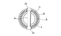
又、実開平4−42924号公報には、図11〜12に示す様な弾性自在継手が記載されている。この公報に記載された弾性自在継手は、操縦安定性の確保と振動減衰性能の確保とを両立させる事を目的としたものである。この弾性自在継手では、シャフト21の端部に溶接固定したハウジング部材22の先端部で直径方向反対位置に、それぞれ円孔23、23を形成している。そして、上記ハウジング部材22の先端部に内嵌固定した緩衝筒3の内側に、第一ヨーク4の基端部を内嵌固定している。更に、この第一ヨーク4の基端部を直径方向に亙って貫通したピン24の両端部を、上記各円孔23、23に遊嵌させている。
【0011】
この様に構成される図11〜12に示した弾性自在継手の場合、シャフト21と第一ヨーク4との間で小さな回転トルクは、上記緩衝筒3を構成する弾性材11を介して伝達する。又、大きな回転トルクを伝達する際には、上記ピン24の両端部外周面が上記円孔23、23の内周縁に衝合する事で、このピン24を介してトルク伝達を行なう。
【0012】
更に、特開平6−329033号公報には、図13に示す様な構造の弾性自在継手が記載されている。この公報に記載された弾性自在継手では、シャフト21の端部に固定したピン24の両端部を、第一ヨーク4の後端縁に形成した切り欠き17に緩く係合させている。又、上記シャフト21にその基端部を固定したハウジング部材22の内周面と上記第一ヨーク4の中間部外周面との間に緩衝筒3を挟持している。
【0013】
この様に構成される図13に示した弾性自在継手の場合、シャフト21と第一ヨーク4との間で小さな回転トルクは、上記緩衝筒3を構成する弾性材11を介して伝達する。又、大きな回転トルクを伝達する際には、上記ピン24の両端部外周面が上記切り欠き17の内縁に衝合する事で、このピン24を介してトルク伝達を行なう。
【0014】
【発明が解決しようとする課題】
上述の様に構成される従来の弾性自在継手の場合、操縦安定性並びに振動減衰性能の確保と小型軽量化とを両立させる事が難しかった。先ず、図8〜10に示した構造の場合には、軽量化を図る事はできるが、操縦安定性の確保と振動減衰性能の確保とを両立させる事が難しい。即ち、操縦安定性を確保すべく、弾性材11の捩り剛性を向上させる為には、この弾性材11の直径を大きくするか、或はこの弾性材11の硬度を高くする必要がある。ところが、この図8〜10に示した構造の場合には、弾性材11を含む緩衝筒3を、第一ヨーク4の内側に嵌合固定している為、弾性材11の直径を大きくする事による捩り剛性の向上は難しい。又、弾性材11の硬度を高くすると、振動減衰性能が劣化してしまう。
【0015】
又、図11〜12に示した構造の場合には、操縦安定性並びに振動減衰性能を確保する事はできても、軽量化を図る事が難しかった。即ち、図11〜12に示した構造の場合には、小さなトルクも大きなトルクもハウジング部材22を介して伝達する為、このハウジング部材22の剛性を十分に大きくする必要がある。従って、このハウジング部材22の板厚を十分に大きくしなければならず、このハウジング部材22の重量が嵩む事が避けられない。更に、ハウジング部材22と緩衝筒3と第一ヨーク4とに互いに整合する円孔を形成する作業(或は各部材22、3、4に予め形成した円孔を整合させる作業)が面倒で、弾性自在継手の生産性を低下させてしまう。
【0016】
更に、図13に示した構造の場合も、操縦安定性並びに振動減衰性能の確保と軽量化とを両立させる事が難しい。即ち、この図13に示した構造の場合には、ピン24の両端部と切り欠き17との係合部と緩衝筒3とが、軸方向にずれた状態で設けられている。従って、緩衝筒3を構成する弾性材11の体積を大きくして操縦安定性並びに振動減衰性能を確保すべく、上記緩衝筒3の軸方向寸法を長くすると、弾性自在継手が大型化し、重量が嵩む。反対に、弾性自在継手の小型軽量化を図るべく、上記緩衝筒3の軸方向寸法を短くすると、弾性材11の体積が不足して操縦安定性の確保と振動減衰性能の確保とを両立させる事ができない。
【0017】
本発明の弾性自在継手は、この様な事情に鑑みて発明したもので、操縦安定性並びに振動減衰性能の確保と軽量化とを両立できる実用的な構造を提供するものである。
【0018】
【課題を解決するための手段】
本発明の弾性自在継手は、次の(1) 〜(9) の要件を総て満たす。
(1) シャフトと、このシャフトの中間部先端寄り部分にその基端部を結合固定した結合ブラケットと、この結合ブラケットの先端部に設けられた外側筒部の内側に緩衝筒を介して内嵌支持された第一ヨークと、第二ヨークと、これら第一、第二両ヨーク同士を連結する十字軸とを備える。
(2) 上記シャフトの先端で、上記緩衝筒の軸方向両端面のうちの上記十字軸側の端面よりもこの十字軸側に突出した部分には、このシャフトの外周面よりも直径方向外方に突出した突片が、このシャフトと一体に固設されている。
(3) 上記緩衝筒は、弾性材を含んで筒状に形成されている。
(4) 上記第一ヨークは、内側筒部と、この内側筒部の軸方向一端縁の直径方向反対位置から軸方向に延びる1対の第一アームと、これら各第一アームの先端部に互いに同心に形成された1対の第一円孔と、上記内側筒部の軸方向両端縁のうちの上記第一アーム側の端縁の一部で上記1対の第一アームから外れた部分に形成された切り欠きとを備え、上記内側筒部は上記緩衝筒に内嵌固定されている。
(5) 上記第二ヨークは、互いに離隔して設けられた1対の第二アームと、これら各第二アームの先端部に互いに同心に形成された1対の第二円孔とを備える。
(6) 上記十字軸の4個所の先端部は、それぞれ1対ずつ設けられた上記第一、第二両円孔の内側に回転自在に支持されている。
(7) 上記シャフトの先端に固設された突片は上記第一ヨークの内側筒部に形成した切り欠きに、隙間をあけて緩く係合している。
(8) 上記シャフトは、円管状のアウターシャフトと円杆状のインナーシャフトとを、回転力の伝達及び摺動自在に組み合わせる事で構成されており、上記突片は、上記アウターシャフトの端部外周面から径方向外方にのみ突出し、このアウターシャフトの端部を上記インナーシャフトが軸方向に通過可能な状態で形成されている。
(9) 上記第一ヨークを構成する上記内側筒部のうちの一部で上記緩衝筒に内嵌固定される部分は、上記切り欠きが形成された部分よりも薄肉である。
【0019】
尚、本発明の弾性自在継手は、シャフトの失端面中央部に孔が形成されている。
【0020】
【作用】
上述の様に構成される弾性自在継手が、非直線上に配置された1対の軸同士の間で回転トルクの伝達を行なう際の作用、及び振動の伝達を防止する際の作用自体は、前述した従来の弾性自在継手と同様である。特に、本発明の弾性自在継手の場合には、緩衝筒を第一ヨークの内側筒部に外嵌固定している為、この緩衝筒の直径を十分に大きくできる。この結果、特に弾性材の硬度を高くしなくても、緩衝筒の捩り剛性を向上させて、操縦安定性を向上させる事ができる。
【0021】
又、緩衝筒を内嵌固定した外側筒部を含む結合ブラケットは、小さな回転トルクのみを伝達し、大きな回転トルクは伝達しない。大きな回転トルクはシャフトの先端に固設した突片が、第一ヨークを構成する内側筒部の切り欠きに衝合する事で、上記結合ブラケットを介する事なく伝達する。従って、上記結合ブラケットには特に大きな剛性を要求されない。この為、結合ブラケットを薄肉化して弾性自在継手の軽量化を図る事が可能になる。
【0022】
又、上記第一ヨークをその先端部に結合固定するシャフトが、衝突事故に伴う大きな衝撃が加わった場合に全長を縮める。
更に、シャフトの先端面中央部に孔を形成している為、シャフトの先端面中央部に孔を形成した分、この先端面と第二ヨークとの距離を短くしても、第二アームの先端縁とシャフトの先端面とが干渉しなくなる。従って、干渉防止の為に第一ヨークを大型化する必要がなくなって、弾性自在継手の小型軽量化を図れる。
【0023】
【実施例】
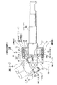
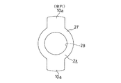
図1〜2は、本発明に関する参考例の第1例を示している。本参考例の弾性自在継手1aは図1に示す様に、シャフト2aと、このシャフト2aの中間部先端寄り部分(図1の左寄り部分)にその基端部を結合固定した結合ブラケット25と、この結合ブラケット25の先端部に設けられた外側筒部26の内側に緩衝筒3を介して内嵌固定された第一ヨーク4と、第二ヨーク5と、この第二ヨーク5と上記第一ヨーク4とを連結する十字軸6とを備える。又、上記シャフト2aの先端部で上記緩衝筒3の直径方向内側に位置する部分には、図2に示す様な形状を有する鍔状の伝達駒部27を、冷間鍛造加工等、適宜の加工方法により、上記シャフト2aと一体に形成している。又、この伝達駒部27の外周縁で直径方向反対側の2個所位置には突片10a、10aを一体形成し、これら各突片10a、10aの先端を上記緩衝筒3の内周面に対向させている。
【0024】
上記シャフト2aの先端面中央部でもある、上記伝達駒部27の中央部には、図1〜2に示す様に、凹部28を形成している。図示の例の場合にこの凹部28は、開口部の形状が円形となる、球状凹面としている。従ってこの凹部28は、中央部が最も深く、周縁部に向かう程次第に浅くなる。
【0025】
又、上記緩衝筒3は、前述した従来構造の場合と同様に、内側スリーブ12の外周面と弾性材11の内周面とを焼き付け若しくは接着により結合し、外側スリーブ13の内周面と上記弾性材11の外周面とを同様に結合して、全体を円筒状に形成している。そして、上記内側スリーブ12を上記第一ヨーク4に設けた、次述する円筒部14に外嵌固定し、外側スリーブ13の片半部(図1の右半部)を上記結合ブラケット25の外側筒部26に内嵌固定している。この状態で上記緩衝筒3を構成する内側スリーブ12の他半部(図1の左半部)は、上記円筒部14の先端縁(図1の左端縁)よりも(後述する第二アーム18、18と干渉しない範囲で)少し突出している。本参考例の場合に上記結合ブラケット25は、鋼板、ステンレス鋼板等の金属板にプレス加工若しくは絞り加工を施す事により、断面クランク形で全体を円環状に形成している。そして、この結合ブラケット25の中心部に形成した結合筒部32を上記シャフト2aに外嵌固定している。尚、上記結合筒部32を外嵌後、シャフト2aの一部を直径方向にかしめ広げて、上記結合ブラケット25の抜け止めを図っている。
【0026】
一方、前記第一ヨーク4は、内側筒部である円筒部14と、この円筒部14の軸方向(図1の左右方向)一端縁(同図の左端縁)の直径方向反対位置から軸方向に延びる1対の第一アーム15とを有する。そして、これら各第一アーム15の先端部(図1の左端部)に、それぞれ第一円孔16(後述の参考例の第2例を示す図3〜4参照)を、互いに同心に形成している。又、上記円筒部14の軸方向一端縁の直径方向反対位置で、上記1対の第一アーム15から外れた部分には、それぞれ切り欠き17、17を形成している。これら各切り欠き17、17の幅寸法は、前記伝達駒部27の突片10a、10aの幅寸法よりも大きい。そして、上記第一ヨーク4の内側にシャフト2aを組み付けた状態で、上記各突片10a、10aは、上記各切り欠き17、17の内側に、隙間をあけて緩く係合している。図1及び前述の説明から明らかな通り、この係合部は、前記緩衝筒3の直径方向内側に存在する。
【0027】
又、前記第二ヨーク5は、例えば厚肉金属板にプレス加工を施す事により造られて、互いに離隔して設けられた1対の第二アーム18、18を有する。この様な第二ヨーク5は、別のシャフト19(図8参照)の端部に、図示しないボルトの緊締に基づいて結合固定される。上記各第二アーム18、18の先端部(図1の右下部)にはそれぞれ第二円孔20、20を、互いに同心に形成している。そして、前記十字軸6の4個所の先端部は、それぞれ1対ずつ設けられた上記第一、第二両円孔16、20の内側に、軸受カップ29、29を含んで構成されるラジアルニードル軸受30、30を介して、回転自在に支持されている。
【0028】
上述の様に構成される弾性自在継手1aの作用は、次の通りである。自動車が直進状態にある場合、或は、ステアリングホイールからシャフト2aに加えられる回転トルクが小さい場合には、シャフト2aの先端部に固定された伝達駒部27の突片10a、10aが、第一ヨーク4の円筒部14に形成した切り欠き17、17の内側中立位置若しくは中立位置から少しだけ偏った位置に存在する。そして、これら各状態では、上記円筒部14と伝達駒部27とが直接接触する事はない。又、上記小さな回転トルクは、前記結合ブラケット25と緩衝筒3とを介して、上記シャフト2aから第一ヨーク4に伝達される。この場合には、車輪からステアリングギヤ、上記別のシャフト19、第二ヨーク5、十字軸6等を介して第一ヨーク4に伝達された振動が、上記緩衝筒3を構成する弾性材11により吸収され、上記シャフト2aまでは伝わらない。この際、上記結合ブラケット25を介して伝達される回転トルクの大きさは限られたものである。
【0029】
これに対して、前輪に大きな舵角を付与する場合等の様に、ステアリングホイールからシャフト2aに加えられる回転トルクが大きい場合には、上記各突片10a、10aが上記各切り欠き17、17の内側面と衝合する。この結果、ステアリングホイールから上記シャフト2aに加えられた回転トルクのうちの多くの部分が、上記伝達駒部27を介して上記第一ヨーク4に伝達される。この状態では、上記緩衝筒3を介して伝達される回転トルクは限られたものとなる。従って、弾性自在継手1aを介して伝達する回転トルクが大きくなった場合でも、上記緩衝筒3を構成する弾性材11に無理な力が作用する事がなくなって、この弾性材11が破損する事が防止される。
【0030】
上述の様に本参考例の弾性自在継手の場合には、緩衝筒3を、内側筒部である第一ヨーク4の円筒部14に(内嵌ではなく)外嵌固定している為、この緩衝筒3の直径を十分に大きくできる。この結果、この緩衝筒3を構成する弾性材11の硬度を特に高くしなくても、この緩衝筒3の捩り剛性を向上させて、操縦安定性を向上させる事ができる。又、弾性材11の硬度を高くする必要がない為、緩衝筒3による振動減衰効果を十分に保持できる。
【0031】
又、上記緩衝筒3を内嵌固定した外側筒部26を含む結合ブラケット25は、弾性自在継手1aを介して伝達される回転トルクの大きさに関係なく、小さな回転トルクのみを伝達し、大きな回転トルクは伝達しない。大きな回転トルクはシャフト2aの先端に固設した突片10a、10aが、第一ヨーク4を構成する円筒部14の切り欠き17、17の内側面に衝合する事で、上記結合ブラケット25を介する事なく伝達する。従って、上記結合ブラケット25には特に大きな剛性を要求されない。この為、結合ブラケット25を薄肉化して弾性自在継手1aの軽量化を図る事が可能になる。
【0032】
又、上記突片10a、10aと切り欠き17、17との係合部が、緩衝筒3の直径方向内側に存在する為、この緩衝筒3を構成する弾性材11の質量を確保すべく、この緩衝筒3の軸方向長さを確保しても、弾性自在継手の軸方向長さが大きくならず、この弾性自在継手の軽量化を図れる。
【0033】
更に、図示の参考例の場合には、前記シャフト2aの先端面に形成した凹部28の存在に基づき、この先端面と前記第二ヨーク5との距離を短くしても、この第二ヨーク5を構成する前記第二アーム18の先端縁とシャフト2aの先端面とが干渉しなくなる。即ち、上記第二ヨーク5が前記十字軸6を中心に揺動すると、上記第二アーム18の先端縁が、上記十字軸6を中心とする円弧状の軌跡を描きつつ上記先端面に近づく。上記先端縁と先端面とが最も近づいた状態では、この先端面の中央部と上記先端縁とが対向する。本参考例の弾性自在継手の場合には、先端面の中央部に上記凹部28が存在する為、これら先端面と先端縁とが干渉しにくくなる。従って、干渉防止の為に第一ヨーク4を大型化する必要がなくなって、弾性自在継手1aの小型軽量化を図れる。言い換えれば、上記凹部28の深さ分だけ、上記第二ヨーク5とシャフト2aとを近づける事が可能になって、上記第一ヨーク4の小型化が可能になる。そして、この小型化により、上記第一ヨーク4の全長が短くなり、絞り加工によりこの第一ヨーク4を成形する際の成形性が向上し、加工コストを低減できる。
【0034】
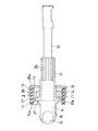
次に、図3〜4は、本発明に関する参考例の第2例を示している。本参考例の場合には、第一ヨーク4をその先端部(図3の左端部)に結合固定するシャフト2bを、衝撃が加わった場合に全長を縮める、所謂コラプシブルシャフトとしている。この為に本参考例では、上記シャフト2bを、円管状のアウターシャフト31と円杆状のインナーシャフト33とを摺動自在に組み合わせる事で構成している。この為に上記アウターシャフト31の基半部(図3の右半部)は先半部(同左半部)に比べて小径とし、この基半部の内周面に雌セレーション溝を形成している。又、上記インナーシャフト31の先端部(図3の左端部)は他の部分に比べて大径とし、この先端部外周面に雄セレーション溝を形成して、この雄セレーション溝と上記雌セレーション溝とを係合させている。又、これら各セレーション溝同士の係合部の一部には、合成樹脂等の摩擦調整部材を設け、これら両セレーション溝同士の係合部が、衝突事故に伴う大きな衝撃を受けた場合にのみ、軸方向(図3の左右方向)に摺動する様にしている。
【0035】
本参考例の場合には、シャフト2bの先半部を構成するアウターシャフト31が円管状であり、このアウターシャフト31の先端部が上記シャフト2bの先端面に開口している。従って、上記アウターシャフト31の、凹部若しくは孔である内側空間の存在により、第二ヨーク5を構成する第二アーム18(図1)の先端縁と上記アウターシャフト31の先端面との干渉を防止できて、その分だけ第一ヨーク4の小型軽量化を図れる。又、上記アウターシャフト31の先端部外周面に形成した1対の突片10a、10aは、このアウターシャフト31の外周面から径方向外方にのみ突出しており、このアウターシャフト31の内周面よりも径方向内方に突出してはいない。その他の構成及び作用は、前述した参考例の第1例と同様である。
【0036】
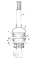
次に、図5〜6は、本発明に関する参考例の第3例(図5)、並びに本発明の実施例(図6)を示している。これら参考例及び実施例の場合には、第一ヨーク4の円筒部14の外周面と結合ブラケット25の外側筒部26の内周面との間に外側緩衝筒36を、上記円筒部14の内周面とシャフト21の外周面との間に内側緩衝筒37を、互いに同心に設けている。この様に、上記円筒部14の外周側と内周側とに外側緩衝筒36と内側緩衝筒37とを二重に設ける事により、シャフト21と第一ヨーク4との間に存在する単位長さあたりの弾性材11、11の体積を増やせる。この為、外側、内側、各緩衝筒36、37を構成する弾性材11、11の硬度を同じとした場合に、捩り剛性をより向上させる事ができる。この為、操縦安定性の確保と振動減衰性能の確保とを、より高いレベルで両立させる事ができる。又、操縦安定性並びに振動減衰性能の確保のレベルを同じとした場合には、単一の緩衝筒を設ける場合に比べて、各緩衝筒36、37の軸方向長さを短くできる。そして、短くした分だけ、弾性自在継手の小型軽量化を図れる。
【0037】
又、上記参考例の第3例及び実施例の場合には、上記シャフト21の先端で、上記外側、内側両緩衝筒36、37の軸方向両端面のうちの十字軸6(図5参照、図6には省略)側の端面よりもこの十字軸6側に突出した部分に、上記シャフト21の外周面よりも直径方向外方に突出した突片10a、10aを、このシャフト21と一体に固設している。
【0038】
尚、上記参考例の第3例及び実施例の場合には、上記内側緩衝筒37の端縁と突片10a、10aとが当接し、当接部を通じて振動が伝達されるのを防止する為、シャフト21の先端部に段部34を形成し、上記内側緩衝筒37を構成する内側スリーブ12の一端縁をこの段部34に突き当てている。又、上記シャフト21の中間部先端寄り部分に形成した別の段部35を直径方向外方にかしめ広げる事で、上記内側スリーブ12の他端縁を抑えている。従ってこの内側スリーブ12は、上記シャフト21の先端部の所定位置に固定される。又、第一ヨーク4の一部で外側スリーブ13を内嵌固定する部分は他の部分よりも薄肉にして、この外側スリーブ13を固定した部分の外径寸法が大きくなるのを防止している。更に、上記シャフト21の先端部外周面にはローレット加工等により細かい凹凸を形成して、このシャフト21に対する内側スリーブ12の回転防止を図っている。その他の構成及び作用は、前述した参考例の第1〜2例と同様である為、重複する説明を省略する。
【0039】
次に、図7は、本発明に関する参考例の第4例を示している。本参考例の場合には、結合ブラケット25aを断面コ字形に形成し、その中央部に設けた結合筒部32を第一ヨーク4の円筒部14の内側に位置させている。本参考例の場合には、上記結合筒部32を外側筒部26の内側に設ける事で、軸方向寸法の短縮が可能になるだけでなく、緩衝筒3から結合ブラケット25aに曲げ応力が加わった場合にも、この結合ブラケット25aがシャフト2bに対して曲げ変形しにくくなる。即ち、上述の参考例の第1〜3例及び実施例の場合には、曲げ中心が上記外側筒部26の軸方向外側に存在する為、この外側筒部26に直径方向に亙る応力が加わった場合に、梃子の原理により、この外側筒部26がシャフト2bに対して傾斜方向に変形し易い。これに対して本参考例の場合には、曲げ中心が上記外側筒部26の内側に存在する為、この外側筒部26がシャフト2bに対して傾斜方向に変形しにくい。
【0040】
【発明の効果】
本発明の弾性自在継手は、以上に述べた通り構成され作用するので、操縦安定性並びに振動減衰性能の確保と軽量化とを両立させる事ができ、又、衝突事故に伴う大きな衝撃が加わった場合にシャフトの全長を縮める事ができ、更に必要に応じて弾性自在継手の小型軽量化を図れる。
【図面の簡単な説明】
【図1】 本発明に関する参考例の第1例を示す部分切断側面図。
【図2】 図1からシャフトの先端部のみを取り出して図1の左方から見た図。
【図3】 本発明に関する参考例の第2例を、十字軸と第二ヨークとを省略して示す、部分切断側面図。
【図4】 図3の左方から見た図。
【図5】 本発明に関する参考例の第3例を示す部分切断側面図。
【図6】 本発明の実施例を、十字軸と第二ヨークとを省略して示す部分切断側面図。
【図7】 本発明に関する参考例の第4例を、十字軸と第二ヨークとを省略して示す部分切断側面図。
【図8】 従来構造の第1例を示す斜視図。
【図9】 十字軸と第二ヨークとを省略して示す、図8のA−A断面図。
【図10】 図9の左方から見た図。
【図11】 従来構造の第2例を示す部分切断側面図。
【図12】 図11のB−B断面図。
【図13】 従来構造の第3例を示す部分切断側面図。
【符号の説明】
1、1a 弾性自在継手
2、2a、2b シャフト
3 緩衝筒
4 第一ヨーク
5 第二ヨーク
6 十字軸
7 セレーション軸部
8、8a 伝達駒
9 中心孔
10、10a 突片
11 弾性材
12 内側スリーブ
13 外側スリーブ
14 円筒部
15 第一アーム
16 第一円孔
17 切り欠き
18 第二アーム
19 別のシャフト
20 第二円孔
21 シャフト
22 ハウジング部材
23 円孔
24 ピン
25、25a 結合ブラケット
26 外側筒部
27 伝達駒部
28 凹部
29 軸受カップ
30 ラジアルニードル軸受
31 アウターシャフト
32 結合筒部
33 インナーシャフト
34、35 段部
36 外側緩衝筒
37 内側緩衝筒[0001]
[Industrial application fields]
The elastic universal joint according to the present invention is incorporated in a steering apparatus for an automobile so that the movement of the steering wheel can be transmitted to the steering gear, and vibration on the steering gear side is prevented from being transmitted to the steering wheel.
[0002]
[Prior art]
The steering apparatus for automobiles is configured to transmit a movement of a steering shaft that is rotationally driven by a steering wheel to a steering gear and to give a steering angle to a front wheel. In general, the steering shaft and the input shaft of the steering gear cannot be arranged on the same straight line. For this reason, a universal joint is provided between the steering shaft and the input shaft so that the movement of the steering wheel can be transmitted to the steering gear. Moreover, in order to prevent the driver from feeling uncomfortable by transmitting the vibration transmitted from the wheel to the steering gear when the automobile is running, it is possible to give the universal joint a vibration absorption capability. It has been performed conventionally. In order to give the universal joint the ability to absorb vibration, a so-called elastic universal joint is generally used in which an elastic material such as rubber is incorporated in the universal joint and vibration transmission is prevented by the elastic material.
[0003]
Conventionally, as such an elastic universal joint, Japanese Patent Laid-Open No. 56-39325 (= French Patent Publication 24644404), Japanese Utility Model Laid-Open No. 54-82257, Japanese Utility Model Laid-Open No. 5-83462, and Japanese Patent Application Laid-Open No. 5-89964, Those described in French Patent Publication 2614985 and the like are known. Since these conventional elastic universal joints have substantially the same basic structure, the structure described in Japanese Utility Model Laid-Open No. 5-89964 will be described with reference to FIGS.
[0004]
As shown in FIG. 8, the elastic
[0005]
Among the constituent members of the elastic
[0006]
The
[0007]
The
[0008]
The operation of the elastic
[0009]
On the other hand, when the rotational torque applied to the
[0010]
Japanese Utility Model Laid-Open No. 4-42924 discloses an elastic universal joint as shown in FIGS. The elastic universal joint described in this publication is intended to achieve both ensuring steering stability and ensuring vibration damping performance. In this elastic universal joint,
[0011]
In the case of the elastic universal joint shown in FIGS. 11 to 12 configured as described above, a small rotational torque is transmitted between the
[0012]
Further, JP-A-6-329033 describes an elastic universal joint having a structure as shown in FIG. In the elastic universal joint described in this publication, both end portions of the
[0013]
In the case of the elastic universal joint shown in FIG. 13 configured as described above, a small rotational torque is transmitted between the
[0014]
[Problems to be solved by the invention]
In the case of the conventional elastic joint configured as described above, it has been difficult to achieve both steering stability and vibration damping performance while reducing the size and weight. First, in the case of the structure shown in FIGS. 8 to 10, it is possible to reduce the weight, but it is difficult to achieve both ensuring steering stability and ensuring vibration damping performance. That is, in order to improve the torsional rigidity of the
[0015]
In addition, in the case of the structure shown in FIGS. 11 to 12, it is difficult to reduce the weight even though the steering stability and the vibration damping performance can be ensured. That is, in the case of the structure shown in FIGS. 11 to 12, since both small torque and large torque are transmitted through the
[0016]
Furthermore, in the case of the structure shown in FIG. 13, it is difficult to achieve both steering stability and vibration damping performance and weight reduction. That is, in the case of the structure shown in FIG. 13, the engaging portion between the both ends of the
[0017]
The elastic universal joint of the present invention was invented in view of such circumstances, and provides a practical structure capable of ensuring both steering stability and vibration damping performance and weight reduction.
[0018]
[Means for Solving the Problems]
The elastic universal joint of the present invention includes the following (1) to(9) Meet all the requirements.
(1) A shaft, a coupling bracket whose base end portion is coupled and fixed to a portion near the distal end of the intermediate portion of the shaft, and an inner fitting through a buffer cylinder inside the outer cylindrical portion provided at the distal end portion of the coupling bracket A supported first yoke, a second yoke, and a cross shaft for connecting the first and second yokes to each other are provided.
(2) At the tip of the shaft, a portion of the both ends in the axial direction of the buffer cylinder that protrudes toward the cross shaft side from the end surface on the cross shaft side is diametrically outward from the outer peripheral surface of the shaft. A projecting piece projecting to the shaft is fixed integrally with the shaft.
(3) The buffer cylinder is formed in a cylindrical shape including an elastic material.
(4) The first yoke includes an inner cylindrical portion, a pair of first arms extending in the axial direction from a position opposite to the diameter direction of one axial end edge of the inner cylindrical portion, and a tip portion of each of the first arms. A portion of the pair of first circular holes formed concentrically with each other and a part of the edge on the first arm side out of both axial end edges of the inner cylindrical portion that is separated from the pair of first arms. And the inner cylinder part is fitted and fixed to the buffer cylinder.
(5) The second yoke includes a pair of second arms provided apart from each other, and a pair of second circular holes formed concentrically at the distal ends of the second arms.
(6) The four tip portions of the cross shaft are rotatably supported inside the first and second circular holes provided in pairs.
(7) The projecting piece fixed to the tip of the shaft is loosely engaged with a notch formed in the inner cylindrical portion of the first yoke with a gap.
(8) The shaft is configured by combining a circular outer shaft and a circular rod-shaped inner shaft so that rotational force can be transmitted and slidable, and the projecting piece is an end portion of the outer shaft. It protrudes only outward in the radial direction from the outer peripheral surface, and is formed in a state in which the inner shaft can pass through the end of the outer shaft in the axial direction.
(9) A part of the inner cylinder part constituting the first yoke that is fitted and fixed to the buffer cylinder is thinner than a part in which the notch is formed.
[0019]
In the present invention,Elastic universal jointThe shaftIn the center of the lost surfaceHoleIs formed.
[0020]
[Action]
The elastic universal joint configured as described above has an action when transmitting rotational torque between a pair of non-linearly arranged shafts and an action itself when preventing transmission of vibration. This is the same as the conventional elastic universal joint described above. In particular,In the case of the elastic universal joint of the present inventionSince the shock-absorbing cylinder is fitted and fixed to the inner cylinder portion of the first yoke, the diameter of the shock-absorbing cylinder is sufficientlyCan be bigger. As a resultEven if the hardness of the elastic material is not particularly increased, the torsional rigidity of the buffer cylinder can be improved and the steering stability can be improved.
[0021]
Further, the coupling bracket including the outer cylinder portion in which the buffer cylinder is fitted and fixed transmits only a small rotational torque and does not transmit a large rotational torque. A large rotational torque is transmitted without going through the coupling bracket by the projecting piece fixed to the tip of the shaft colliding with the notch of the inner cylindrical portion constituting the first yoke. Therefore, the coupling bracket is not required to have particularly great rigidity. For this reason, it is possible to reduce the weight of the elastic universal joint by thinning the coupling bracket.
[0022]
Further, the shaft for coupling and fixing the first yoke to the tip thereof shortens the overall length when a large impact is applied due to a collision accident.
Furthermore, at the center of the tip end surface of the shaftBecause it forms a holeIn the center of the shaft tipHoleTherefore, even if the distance between the tip surface and the second yoke is shortened, the tip edge of the second arm and the tip surface of the shaft do not interfere with each other. Therefore, it is not necessary to increase the size of the first yoke to prevent interference, and the elastic universal joint can be reduced in size and weight.
[0023]
【Example】
1 and 2 show a first example of a reference example related to the present invention.Reference exampleAs shown in FIG. 1, the elastic universal joint 1a includes a
[0024]
As shown in FIGS. 1 and 2, a
[0025]
Further, the
[0026]
On the other hand, the
[0027]
The
[0028]
The operation of the elastic universal joint 1a configured as described above is as follows. When the automobile is in a straight traveling state or when the rotational torque applied to the
[0029]
On the other hand, when the rotational torque applied to the
[0030]
As aboveReference exampleIn the case of the elastic universal joint, since the
[0031]
Further, the
[0032]
In addition, since the engaging portions of the projecting
[0033]
In addition, as shownReference exampleIn this case, the
[0034]
Next, FIGS.Second example of a reference example related to the present inventionIs shown.Reference exampleIn this case, the
[0035]
Reference exampleIn this case, the
[0036]
Next, FIGS.A third example (FIG. 5) of a reference example related to the present invention and an example (FIG. 6) of the present invention are shown. In the case of these reference examples and examples,An outer buffer cylinder 36 is provided between the outer peripheral surface of the
[0037]
Further, in the case of the third example and the example of the reference example, the cross shaft 6 (see FIG. 5) of the axial end ends of the outer and inner buffer cylinders 36 and 37 at the tip of the
[0038]
still,Third example and example of the above reference exampleIn this case, the edge of the inner buffer cylinder 37 and the projecting
[0039]
Next, FIG.Fourth example of reference example related to the present inventionIs shown.Reference exampleIn this case, the
[0040]
【The invention's effect】
Since the elastic universal joint of the present invention is configured and operates as described above, it is possible to achieve both steering stability and vibration damping performance and light weight, and a large impact is applied due to a collision accident. In this case, the overall length of the shaft can be reduced, and the elastic universal joint can be reduced in size and weight as required.
[Brief description of the drawings]
FIG. 1 is a partially cut side view showing a first example of a reference example related to the present invention.
FIG. 2 is a view taken from the left side of FIG. 1 with only the tip portion of the shaft taken out from FIG.
FIG. 3Second example of reference exampleFIG. 5 is a partially cut side view showing the cross shaft and the second yoke.
4 is a diagram viewed from the left side of FIG. 3;
FIG. 5 shows a reference example related to the present invention.Third exampleFIG.
FIG. 6 of the present inventionExampleFIG. 4 is a partially cut side view showing the cross shaft and the second yoke.
[Fig. 7]Fourth example of reference example related to the present inventionFIG. 4 is a partially cut side view showing the cross shaft and the second yoke.
FIG. 8 is a perspective view showing a first example of a conventional structure.
9 is a cross-sectional view taken along the line AA in FIG. 8, omitting the cross shaft and the second yoke.
10 is a view from the left side of FIG. 9;
FIG. 11 is a partially cut side view showing a second example of a conventional structure.
12 is a sectional view taken along line BB in FIG.
FIG. 13 is a partially cutaway side view showing a third example of the conventional structure.
[Explanation of symbols]
1, 1a Elastic universal joint
2, 2a, 2b shaft
3 Buffer cylinder
4 First yoke
5 Second York
6 Cross axis
7 Serration shaft
8, 8a Transmission piece
9 Center hole
10, 10a
11 Elastic material
12 Inner sleeve
13 Outer sleeve
14 Cylindrical part
15 First arm
16 1st hole
17 Notch
18 Second arm
19 Another shaft
20 Second circular hole
21 Shaft
22 Housing member
23 hole
24 pin
25, 25a Connecting bracket
26 Outer cylinder
27 Transmission piece
28 recess
29 Bearing cup
30 radial needle bearings
31 Outer shaft
32 coupling cylinder
33 Inner shaft
34, 35 steps
36 Outer buffer cylinder
37 Inside buffer cylinder
Claims (1)
(1) シャフトと、このシャフトの中間部先端寄り部分にその基端部を結合固定した結合ブラケットと、この結合ブラケットの先端部に設けられた外側筒部の内側に緩衝筒を介して内嵌支持された第一ヨークと、第二ヨークと、これら第一、第二両ヨーク同士を連結する十字軸とを備える。
(2) 上記シャフトの先端で、上記緩衝筒の軸方向両端面のうちの上記十字軸側の端面よりもこの十字軸側に突出した部分には、このシャフトの外周面よりも直径方向外方に突出した突片が、このシャフトと一体に固設されている。
(3) 上記緩衝筒は、弾性材を含んで筒状に形成されている。
(4) 上記第一ヨークは、内側筒部と、この内側筒部の軸方向一端縁の直径方向反対位置から軸方向に延びる1対の第一アームと、これら各第一アームの先端部に互いに同心に形成された1対の第一円孔と、上記内側筒部の軸方向両端縁のうちの上記第一アーム側の端縁の一部で上記1対の第一アームから外れた部分に形成された切り欠きとを備え、上記内側筒部は上記緩衝筒に内嵌固定されている。
(5) 上記第二ヨークは、互いに離隔して設けられた1対の第二アームと、これら各第二アームの先端部に互いに同心に形成された1対の第二円孔とを備える。
(6) 上記十字軸の4個所の先端部は、それぞれ1対ずつ設けられた上記第一、第二両円孔の内側に回転自在に支持されている。
(7) 上記シャフトの先端に固設された突片は上記第一ヨークの内側筒部に形成した切り欠きに、隙間をあけて緩く係合している。
(8) 上記シャフトは、円管状のアウターシャフトと円杆状のインナーシャフトとを、回転力の伝達及び摺動自在に組み合わせる事で構成されており、上記突片は、上記アウターシャフトの端部外周面から径方向外方にのみ突出し、このアウターシャフトの端部を上記インナーシャフトが軸方向に通過可能な状態で形成されている。
(9) 上記第一ヨークを構成する上記内側筒部のうちの一部で上記緩衝筒に内嵌固定される部分は、上記切り欠きが形成された部分よりも薄肉である。 An elastic universal joint that satisfies all the following requirements (1) to (9) .
(1) A shaft, a coupling bracket whose base end portion is coupled and fixed to a portion near the distal end of the intermediate portion of the shaft, and an inner fitting through a buffer cylinder inside the outer cylindrical portion provided at the distal end portion of the coupling bracket A supported first yoke, a second yoke, and a cross shaft for connecting the first and second yokes to each other are provided.
(2) At the tip of the shaft, a portion of the both ends in the axial direction of the buffer cylinder that protrudes toward the cross shaft side from the end surface on the cross shaft side is diametrically outward from the outer peripheral surface of the shaft. A projecting piece projecting to the shaft is fixed integrally with the shaft.
(3) The buffer cylinder is formed in a cylindrical shape including an elastic material.
(4) The first yoke includes an inner cylindrical portion, a pair of first arms extending in the axial direction from a position opposite to the diameter direction of one axial end edge of the inner cylindrical portion, and a tip portion of each of the first arms. A portion of the pair of first circular holes formed concentrically with each other and a part of the edge on the first arm side out of both axial end edges of the inner cylindrical portion that is separated from the pair of first arms. And the inner cylinder part is fitted and fixed to the buffer cylinder.
(5) The second yoke includes a pair of second arms provided apart from each other, and a pair of second circular holes formed concentrically at the distal ends of the second arms.
(6) The four tip portions of the cross shaft are rotatably supported inside the first and second circular holes provided in pairs.
(7) The projecting piece fixed to the tip of the shaft is loosely engaged with a notch formed in the inner cylindrical portion of the first yoke with a gap.
(8) The shaft is configured by combining a circular outer shaft and a circular rod-shaped inner shaft so that rotational force can be transmitted and slidable, and the projecting piece is an end portion of the outer shaft. It protrudes only outward in the radial direction from the outer peripheral surface, and is formed in a state in which the inner shaft can pass through the end of the outer shaft in the axial direction.
(9) A part of the inner cylinder part constituting the first yoke that is fitted and fixed to the buffer cylinder is thinner than a part in which the notch is formed.
Priority Applications (1)
| Application Number | Priority Date | Filing Date | Title |
|---|---|---|---|
| JP2002290727A JP4070567B2 (en) | 2002-10-03 | 2002-10-03 | Elastic universal joint |
Applications Claiming Priority (1)
| Application Number | Priority Date | Filing Date | Title |
|---|---|---|---|
| JP2002290727A JP4070567B2 (en) | 2002-10-03 | 2002-10-03 | Elastic universal joint |
Related Parent Applications (1)
| Application Number | Title | Priority Date | Filing Date |
|---|---|---|---|
| JP01005095A Division JP3389721B2 (en) | 1994-12-16 | 1995-01-25 | Elastic universal joint |
Publications (2)
| Publication Number | Publication Date |
|---|---|
| JP2003113853A JP2003113853A (en) | 2003-04-18 |
| JP4070567B2 true JP4070567B2 (en) | 2008-04-02 |
Family
ID=19197164
Family Applications (1)
| Application Number | Title | Priority Date | Filing Date |
|---|---|---|---|
| JP2002290727A Expired - Lifetime JP4070567B2 (en) | 2002-10-03 | 2002-10-03 | Elastic universal joint |
Country Status (1)
| Country | Link |
|---|---|
| JP (1) | JP4070567B2 (en) |
Families Citing this family (1)
| Publication number | Priority date | Publication date | Assignee | Title |
|---|---|---|---|---|
| WO2020105582A1 (en) * | 2018-11-22 | 2020-05-28 | 日本精工株式会社 | Torque transmission shaft |
-
2002
- 2002-10-03 JP JP2002290727A patent/JP4070567B2/en not_active Expired - Lifetime
Also Published As
| Publication number | Publication date |
|---|---|
| JP2003113853A (en) | 2003-04-18 |
Similar Documents
| Publication | Publication Date | Title |
|---|---|---|
| US5916026A (en) | Elastic universal joint | |
| JP3646556B2 (en) | Elastic shaft coupling | |
| US20060116209A1 (en) | Elastic shaft joint and elastic bush forming method | |
| JP3627441B2 (en) | Elastic shaft coupling | |
| US6022047A (en) | Universal joint and a yoke therefor for a steering apparatus | |
| JP2000035049A (en) | Universal joint | |
| JPH1089373A (en) | Elastic shaft joint | |
| JP2532378Y2 (en) | Elastic universal joint | |
| JP4070567B2 (en) | Elastic universal joint | |
| JP2001323920A (en) | Structure for fitting spline shaft for constant velocity joint | |
| JPH08200382A (en) | Elastic universal joint | |
| JP2586569Y2 (en) | Energy absorbing intermediate shaft | |
| JPH10250390A (en) | Shock absorption structure of propeller shaft | |
| JPH08170647A (en) | Elastic universal joint | |
| JPH1019054A (en) | Elastic coupling | |
| JP3661327B2 (en) | Universal joint yoke | |
| JPH0422111Y2 (en) | ||
| GB2322687A (en) | Elastic universal joint assembly | |
| JP2001140918A (en) | Elastic shaft coupling | |
| JP3769846B2 (en) | Elastic universal joint | |
| JP2001027256A (en) | Elastic coupling | |
| WO2005075845A1 (en) | Fixed constant velocity universal joint | |
| JPH09229086A (en) | Elastic shaft joint | |
| WO2005078300A1 (en) | Constant velocity universal joint | |
| JPH09229085A (en) | Elastic shaft coupling |
Legal Events
| Date | Code | Title | Description |
|---|---|---|---|
| A977 | Report on retrieval |
Free format text: JAPANESE INTERMEDIATE CODE: A971007 Effective date: 20060123 |
|
| A131 | Notification of reasons for refusal |
Free format text: JAPANESE INTERMEDIATE CODE: A131 Effective date: 20060214 |
|
| A521 | Written amendment |
Free format text: JAPANESE INTERMEDIATE CODE: A523 Effective date: 20060412 |
|
| A02 | Decision of refusal |
Free format text: JAPANESE INTERMEDIATE CODE: A02 Effective date: 20060523 |
|
| A521 | Written amendment |
Free format text: JAPANESE INTERMEDIATE CODE: A523 Effective date: 20060629 |
|
| A911 | Transfer to examiner for re-examination before appeal (zenchi) |
Free format text: JAPANESE INTERMEDIATE CODE: A911 Effective date: 20060725 |
|
| A912 | Re-examination (zenchi) completed and case transferred to appeal board |
Free format text: JAPANESE INTERMEDIATE CODE: A912 Effective date: 20060908 |
|
| A61 | First payment of annual fees (during grant procedure) |
Free format text: JAPANESE INTERMEDIATE CODE: A61 Effective date: 20080115 |
|
| R150 | Certificate of patent or registration of utility model |
Free format text: JAPANESE INTERMEDIATE CODE: R150 |
|
| FPAY | Renewal fee payment (event date is renewal date of database) |
Free format text: PAYMENT UNTIL: 20110125 Year of fee payment: 3 |
|
| FPAY | Renewal fee payment (event date is renewal date of database) |
Free format text: PAYMENT UNTIL: 20120125 Year of fee payment: 4 |
|
| FPAY | Renewal fee payment (event date is renewal date of database) |
Free format text: PAYMENT UNTIL: 20130125 Year of fee payment: 5 |
|
| FPAY | Renewal fee payment (event date is renewal date of database) |
Free format text: PAYMENT UNTIL: 20130125 Year of fee payment: 5 |
|
| FPAY | Renewal fee payment (event date is renewal date of database) |
Free format text: PAYMENT UNTIL: 20140125 Year of fee payment: 6 |
|
| EXPY | Cancellation because of completion of term |