WO2020105192A1 - 走行装置 - Google Patents
走行装置Info
- Publication number
- WO2020105192A1 WO2020105192A1 PCT/JP2018/043283 JP2018043283W WO2020105192A1 WO 2020105192 A1 WO2020105192 A1 WO 2020105192A1 JP 2018043283 W JP2018043283 W JP 2018043283W WO 2020105192 A1 WO2020105192 A1 WO 2020105192A1
- Authority
- WO
- WIPO (PCT)
- Prior art keywords
- unit
- traveling
- power transmission
- movable
- power
- Prior art date
- Legal status (The legal status is an assumption and is not a legal conclusion. Google has not performed a legal analysis and makes no representation as to the accuracy of the status listed.)
- Ceased
Links
Images



Classifications
-
- B—PERFORMING OPERATIONS; TRANSPORTING
- B60—VEHICLES IN GENERAL
- B60L—PROPULSION OF ELECTRICALLY-PROPELLED VEHICLES; SUPPLYING ELECTRIC POWER FOR AUXILIARY EQUIPMENT OF ELECTRICALLY-PROPELLED VEHICLES; ELECTRODYNAMIC BRAKE SYSTEMS FOR VEHICLES IN GENERAL; MAGNETIC SUSPENSION OR LEVITATION FOR VEHICLES; MONITORING OPERATING VARIABLES OF ELECTRICALLY-PROPELLED VEHICLES; ELECTRIC SAFETY DEVICES FOR ELECTRICALLY-PROPELLED VEHICLES
- B60L13/00—Electric propulsion for monorail vehicles, suspension vehicles or rack railways; Magnetic suspension or levitation for vehicles
- B60L13/03—Electric propulsion by linear motors
-
- B—PERFORMING OPERATIONS; TRANSPORTING
- B60—VEHICLES IN GENERAL
- B60L—PROPULSION OF ELECTRICALLY-PROPELLED VEHICLES; SUPPLYING ELECTRIC POWER FOR AUXILIARY EQUIPMENT OF ELECTRICALLY-PROPELLED VEHICLES; ELECTRODYNAMIC BRAKE SYSTEMS FOR VEHICLES IN GENERAL; MAGNETIC SUSPENSION OR LEVITATION FOR VEHICLES; MONITORING OPERATING VARIABLES OF ELECTRICALLY-PROPELLED VEHICLES; ELECTRIC SAFETY DEVICES FOR ELECTRICALLY-PROPELLED VEHICLES
- B60L5/00—Current collectors for power supply lines of electrically-propelled vehicles
-
- B—PERFORMING OPERATIONS; TRANSPORTING
- B60—VEHICLES IN GENERAL
- B60L—PROPULSION OF ELECTRICALLY-PROPELLED VEHICLES; SUPPLYING ELECTRIC POWER FOR AUXILIARY EQUIPMENT OF ELECTRICALLY-PROPELLED VEHICLES; ELECTRODYNAMIC BRAKE SYSTEMS FOR VEHICLES IN GENERAL; MAGNETIC SUSPENSION OR LEVITATION FOR VEHICLES; MONITORING OPERATING VARIABLES OF ELECTRICALLY-PROPELLED VEHICLES; ELECTRIC SAFETY DEVICES FOR ELECTRICALLY-PROPELLED VEHICLES
- B60L50/00—Electric propulsion with power supplied within the vehicle
- B60L50/40—Electric propulsion with power supplied within the vehicle using propulsion power supplied by capacitors
-
- B—PERFORMING OPERATIONS; TRANSPORTING
- B60—VEHICLES IN GENERAL
- B60L—PROPULSION OF ELECTRICALLY-PROPELLED VEHICLES; SUPPLYING ELECTRIC POWER FOR AUXILIARY EQUIPMENT OF ELECTRICALLY-PROPELLED VEHICLES; ELECTRODYNAMIC BRAKE SYSTEMS FOR VEHICLES IN GENERAL; MAGNETIC SUSPENSION OR LEVITATION FOR VEHICLES; MONITORING OPERATING VARIABLES OF ELECTRICALLY-PROPELLED VEHICLES; ELECTRIC SAFETY DEVICES FOR ELECTRICALLY-PROPELLED VEHICLES
- B60L50/00—Electric propulsion with power supplied within the vehicle
- B60L50/50—Electric propulsion with power supplied within the vehicle using propulsion power supplied by batteries or fuel cells
-
- B—PERFORMING OPERATIONS; TRANSPORTING
- B60—VEHICLES IN GENERAL
- B60L—PROPULSION OF ELECTRICALLY-PROPELLED VEHICLES; SUPPLYING ELECTRIC POWER FOR AUXILIARY EQUIPMENT OF ELECTRICALLY-PROPELLED VEHICLES; ELECTRODYNAMIC BRAKE SYSTEMS FOR VEHICLES IN GENERAL; MAGNETIC SUSPENSION OR LEVITATION FOR VEHICLES; MONITORING OPERATING VARIABLES OF ELECTRICALLY-PROPELLED VEHICLES; ELECTRIC SAFETY DEVICES FOR ELECTRICALLY-PROPELLED VEHICLES
- B60L53/00—Methods of charging batteries, specially adapted for electric vehicles; Charging stations or on-board charging equipment therefor; Exchange of energy storage elements in electric vehicles
-
- B—PERFORMING OPERATIONS; TRANSPORTING
- B60—VEHICLES IN GENERAL
- B60L—PROPULSION OF ELECTRICALLY-PROPELLED VEHICLES; SUPPLYING ELECTRIC POWER FOR AUXILIARY EQUIPMENT OF ELECTRICALLY-PROPELLED VEHICLES; ELECTRODYNAMIC BRAKE SYSTEMS FOR VEHICLES IN GENERAL; MAGNETIC SUSPENSION OR LEVITATION FOR VEHICLES; MONITORING OPERATING VARIABLES OF ELECTRICALLY-PROPELLED VEHICLES; ELECTRIC SAFETY DEVICES FOR ELECTRICALLY-PROPELLED VEHICLES
- B60L55/00—Arrangements for supplying energy stored within a vehicle to a power network, i.e. vehicle-to-grid [V2G] arrangements
-
- B—PERFORMING OPERATIONS; TRANSPORTING
- B60—VEHICLES IN GENERAL
- B60L—PROPULSION OF ELECTRICALLY-PROPELLED VEHICLES; SUPPLYING ELECTRIC POWER FOR AUXILIARY EQUIPMENT OF ELECTRICALLY-PROPELLED VEHICLES; ELECTRODYNAMIC BRAKE SYSTEMS FOR VEHICLES IN GENERAL; MAGNETIC SUSPENSION OR LEVITATION FOR VEHICLES; MONITORING OPERATING VARIABLES OF ELECTRICALLY-PROPELLED VEHICLES; ELECTRIC SAFETY DEVICES FOR ELECTRICALLY-PROPELLED VEHICLES
- B60L58/00—Methods or circuit arrangements for monitoring or controlling batteries or fuel cells, specially adapted for electric vehicles
-
- B—PERFORMING OPERATIONS; TRANSPORTING
- B60—VEHICLES IN GENERAL
- B60M—POWER SUPPLY LINES, AND DEVICES ALONG RAILS, FOR ELECTRICALLY- PROPELLED VEHICLES
- B60M7/00—Power lines or rails specially adapted for electrically-propelled vehicles of special types, e.g. suspension tramway, ropeway, underground railway
-
- B—PERFORMING OPERATIONS; TRANSPORTING
- B65—CONVEYING; PACKING; STORING; HANDLING THIN OR FILAMENTARY MATERIAL
- B65G—TRANSPORT OR STORAGE DEVICES, e.g. CONVEYORS FOR LOADING OR TIPPING, SHOP CONVEYOR SYSTEMS OR PNEUMATIC TUBE CONVEYORS
- B65G54/00—Non-mechanical conveyors not otherwise provided for
- B65G54/02—Non-mechanical conveyors not otherwise provided for electrostatic, electric, or magnetic
-
- Y—GENERAL TAGGING OF NEW TECHNOLOGICAL DEVELOPMENTS; GENERAL TAGGING OF CROSS-SECTIONAL TECHNOLOGIES SPANNING OVER SEVERAL SECTIONS OF THE IPC; TECHNICAL SUBJECTS COVERED BY FORMER USPC CROSS-REFERENCE ART COLLECTIONS [XRACs] AND DIGESTS
- Y02—TECHNOLOGIES OR APPLICATIONS FOR MITIGATION OR ADAPTATION AGAINST CLIMATE CHANGE
- Y02T—CLIMATE CHANGE MITIGATION TECHNOLOGIES RELATED TO TRANSPORTATION
- Y02T10/00—Road transport of goods or passengers
- Y02T10/60—Other road transportation technologies with climate change mitigation effect
- Y02T10/70—Energy storage systems for electromobility, e.g. batteries
-
- Y—GENERAL TAGGING OF NEW TECHNOLOGICAL DEVELOPMENTS; GENERAL TAGGING OF CROSS-SECTIONAL TECHNOLOGIES SPANNING OVER SEVERAL SECTIONS OF THE IPC; TECHNICAL SUBJECTS COVERED BY FORMER USPC CROSS-REFERENCE ART COLLECTIONS [XRACs] AND DIGESTS
- Y02—TECHNOLOGIES OR APPLICATIONS FOR MITIGATION OR ADAPTATION AGAINST CLIMATE CHANGE
- Y02T—CLIMATE CHANGE MITIGATION TECHNOLOGIES RELATED TO TRANSPORTATION
- Y02T10/00—Road transport of goods or passengers
- Y02T10/60—Other road transportation technologies with climate change mitigation effect
- Y02T10/7072—Electromobility specific charging systems or methods for batteries, ultracapacitors, supercapacitors or double-layer capacitors
-
- Y—GENERAL TAGGING OF NEW TECHNOLOGICAL DEVELOPMENTS; GENERAL TAGGING OF CROSS-SECTIONAL TECHNOLOGIES SPANNING OVER SEVERAL SECTIONS OF THE IPC; TECHNICAL SUBJECTS COVERED BY FORMER USPC CROSS-REFERENCE ART COLLECTIONS [XRACs] AND DIGESTS
- Y02—TECHNOLOGIES OR APPLICATIONS FOR MITIGATION OR ADAPTATION AGAINST CLIMATE CHANGE
- Y02T—CLIMATE CHANGE MITIGATION TECHNOLOGIES RELATED TO TRANSPORTATION
- Y02T90/00—Enabling technologies or technologies with a potential or indirect contribution to GHG emissions mitigation
- Y02T90/10—Technologies relating to charging of electric vehicles
- Y02T90/14—Plug-in electric vehicles
Definitions
- the present specification relates to a traveling device including a movable portion that can travel along a traveling path formed in a fixed portion, and more specifically, relates to a traveling device that performs non-contact power supply from the fixed portion to the movable portion.
- the traveling device includes a fixed portion on which a traveling path is formed and a movable portion that can travel along the traveling path.
- Many traveling devices are applied to the use of a transport device that loads and transports products and equipment.
- As driving modes of the traveling device rotational driving of wheels by a motor, generation of propulsive force by a linear motor, and the like are used. Further, a configuration in which a contactless power feeding technique is combined to feed power to a moving movable portion is also used.
- Patent Document 1 discloses a technical example of a traveling device that is contactlessly powered.
- the sorting facility disclosed in Patent Document 1 includes a traveling route, a traveling vehicle, a guide line along the traveling route, and a coil provided on the traveling vehicle and supplied with power from the guide line in a non-contact manner.
- the traveling path is formed of a conductive member, and the wheels of the traveling carriage are conductive wheels. According to this, it is said that the electric charge generated in the wheel is escaped from the conductive wheel to the traveling route, and the generation of static electricity can be prevented.
- a fixed portion in which a traveling path is formed a power transmission portion provided in the fixed portion, which supplies electric power, a movable portion capable of traveling along the traveling path, and provided in the movable portion,
- a power receiving unit that receives the electric power from the power transmitting unit in a non-contact manner, a traveling drive unit that is provided in the movable unit, operates by the electric power received by the power receiving unit, and drives the movable unit, and the fixed unit.
- An approach sensing unit that senses that an operator approaches, and a power transmission that regulates the power supplied by the power transmitting unit to a specified level or less when the approach sensing unit senses the approach of the operator to the fixed unit.
- a traveling device including a restriction unit.
- the power transmission regulation part regulates the electric power supplied by the power transmission part to be equal to or lower than a prescribed level.
- the voltage generated in the power transmission section of the fixed section and the voltage generated in the power reception section of the movable section are suppressed to be lower than in the normal state, so that the operator can be reliably protected.
- it is not necessary to secure a large space distance or a creepage distance in order to surely protect the operator it is possible to downsize the movable portion.
- FIG. 6 is a cross-sectional view of the fixed part taken along the YZ plane. It is a side view of the movable part seen from the X direction. It is a block diagram explaining a control configuration and a power supply path of the traveling apparatus of the embodiment. It is a figure which shows the first half of the control flow in which a high-order control part controls traveling of a some movable part. It is a figure which shows the latter half of the control flow in which a higher-order control part controls traveling of a some movable part.
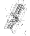
- FIG. 1 is a plan view schematically showing a device configuration of a traveling device 1 of the embodiment.
- the traveling device 1 includes a fixed unit 2, a power transmission unit 29, a movable unit 3, a power receiving unit 36, a traveling drive unit 3C, a protective cover 5, an approach sensing unit 6, a power transmission regulation unit 24, and a traveling control unit 82 (see FIG. 5).
- FIG. 2 is a perspective view showing a configuration of a part of the fixed part 2 and the movable part 3, and a part of the members is omitted.
- FIG. 3 is a cross-sectional view of the fixing portion 2 taken along the YZ plane.
- FIG. 4 is a side view of the movable portion 4 viewed from the X direction, and some members are omitted.
- the fixed part 2 is configured by connecting a plurality of section units 21.
- the section unit 21 includes a curved line unit and a Y-shaped branch unit in addition to the linear unit illustrated.
- a travel path is formed in each section unit 21 of the fixed portion 2.
- the traveling roads are continuous for a long time to form a straight road, a curved road, a branch road, a peripheral circuit, or the like.
- the shape of the traveling path is changed by changing the connection order.
- the fixed portion 2 can be extended by adding the section unit 21.
- the movable part 3 is mounted on the fixed part 2 and travels along the traveling path.
- the length of the movable portion 3 in the X direction is smaller than the length of the section unit 21.
- the movable part 3 is formed so that a work can be placed on the work table 32 on the upper surface thereof.
- the traveling device 1 can be configured to include a plurality of movable parts 3. The plurality of movable parts 3 travel under the control of the travel control part 82 to avoid a collision.
- the protective cover 5 is shown by a broken line for convenience in FIG. 1, and is provided in each of the section units 21.
- One side 51 of the protective cover 5 that is long in the X direction is attached to one side edge of the section unit 21 so as to be openable and closable by using a pair of hinges 52.
- the protective cover 5 is made of transparent resin and is formed in a shape that bulges upward.
- the protective cover 5 is normally closed and covers the fixed part 2 and the moving movable part 3 to protect the operator.
- a rectangular cutout window 54 is formed near the other side 53 of the protective cover 5. Through the cutout window 54, the work of loading and unloading the work on the work table 32 of the movable part 3 is performed. Further, the work on the workbench 32 is processed or assembled through the cutout window 54. These operations are performed by an unillustrated work robot.
- the approach sensing unit 6 is provided in each of the section units 21.
- the proximity sensor 6 is arranged near the other side 53 of the protective cover 5.
- An open / close sensor that detects an opening operation of the protective cover 5 that is normally closed is used as the approach sensing unit 6. That is, the approach sensing unit 6 senses the approach of the operator to the fixed unit 2 by detecting the operation of the operator opening the protective cover 5.
- each of the section units 21 forming the fixed part 2 has a device configuration similar to each other. Therefore, in the following description, the configuration of one section unit 21 will be described as the configuration of the fixed portion 2.
- the fixing portion 2 is configured with the bottom plate 22 and the pair of side plates 23 as main structural members, and opens upward.
- the fixed portion 2 has a bilaterally symmetrical structure in the Y direction.
- the bottom plate 22 has a thin box shape that opens downward.
- the power transmission restriction unit 24 is attached to the lower side of the bottom plate 22.
- the power transmission regulation unit 24 functions as a power supply unit that normally performs non-contact power supply.
- the pair of side plates 23 are erected on the upper surface of the bottom plate 22 in parallel with each other.
- a plurality of magnets 25 are provided on the inner surfaces of the pair of side plates 23.
- Each of the magnets 25 is formed in a plate shape that is long in the Z direction.
- the plurality of magnets 25 are arranged such that the N poles and the S poles alternately appear in the X direction on the inner sides facing each other.
- a rail portion 26 extending in the X direction is provided on the upper surface of the side plate 23.
- the inner side surface of the rail portion 26 is formed in a V shape.
- a linear scale 27 extending in the X direction is attached to the upper surface of one rail portion 26 (left side in FIG. 3).
- a traveling rail 28 is provided in the center of the upper side of the bottom plate 22 in the Y direction.
- the traveling rail 28 extends in the X direction and is formed in a groove shape that opens upward.
- the traveling rail 28 and the pair of rail portions 26 form a traveling path along which the movable portion 3 travels.
- the lower parts of the pair of side plates 23 are bent inward to approach the traveling rail 28.
- the power transmission unit 29 is disposed on the upper surface of the lower portion of each of the pair of side plates 23.
- Each of the pair of power transmission units 29 is a power transmission coil extending in the X direction.
- the power transmission coil includes a winding 2A and a core 2B.
- the core 2B is formed using a magnetic material such as ferrite or electromagnetic steel plate.
- the cross section of the core 2B taken along the YZ plane has an E shape that opens upward.
- the power transmission unit 29 is supplied with power from the power transmission regulation unit 24 and supplies power to the power reception unit 36 described below in a contactless manner.
- the movable part 3 includes a main body 31 and a workbench 32.
- the main body 31 is formed in a box shape that is long in the X direction, and various members to be described later are arranged inside.
- the workbench 32 is formed in a rectangular thin plate shape and is fixed to the upper side of the main body 31.
- the workbench 32 is engraved with a round hole into which a projection on the bottom surface of the work is inserted. As a result, the work is stably placed and does not shake or shift even while the movable portion 3 is running.
- a groove roller 33 is provided near the top of the main body 31. Three groove rollers 33 are arranged in the X direction and two sets are provided in the Y direction for a total of six groove rollers 33. The groove roller 33 slides from the inside onto the V-shaped portion of the rail portion 26 of the fixed portion 2.
- a traveling roller 34 is provided on the lower surface of the main body 31. Two traveling rollers 34 are arranged in the Y direction as one set, and a plurality of traveling rollers 34 are provided separately in the X direction. The traveling roller 34 slides on the inner side surface of the traveling rail 28 of the fixed portion 2. The groove roller 33 and the traveling roller 34 allow the movable portion 3 to travel.
- a position detector 35 is provided at one end in the Y direction on the top of the main body 31.
- the position detection unit 35 is arranged to face the linear scale 27 of the fixed unit 2.
- the position detection unit 35 detects the scale of the linear scale 27 to detect the current position of the movable unit 3 on the traveling path.
- Examples of the detection method of the position detection unit 35 and the linear scale 27 include an optical detection method and a detection method using electromagnetic induction, but the detection method is not limited to these.
- a pair of power receiving units 36 are provided on the lower surface of the main body 31 outside the traveling rollers 34 in the Y direction.
- Each of the pair of power receiving units 36 is a power receiving coil extending in the X direction.
- the power receiving coil includes a winding 37 and a core 38.
- the core 38 is formed using the same material as the core 2B of the power transmission unit 29.
- a cross section of the core 38 taken along the YZ plane has an E shape that opens downward.
- the power receiving unit 36 is arranged to face the power transmitting unit 29 of any of the fixed units 2 regardless of the current position of the movable unit 3. As a result, the core 2B of the power transmission unit and the core 38 of the power reception unit 36 approach each other and are magnetically coupled, and jointly form a circulating magnetic path. Therefore, the power receiving unit 36 can receive the power from the power transmission unit 29 by the non-contact power feeding of the electromagnetic coupling method.
- a power receiving circuit 39, a wireless communication unit 3A, and a linear control unit 3B are provided near the center of the main body unit 31. Further, a pair of traveling drive units 3C is provided on both side surfaces in the Y direction of the intermediate height of the main body unit 31.
- the power receiving circuit 39 transforms the power received by the power receiving unit 36 and supplies power to the wireless communication unit 3A and the linear control unit 3B.
- the linear control unit 3B controls the electric power supplied to the traveling drive unit 3C.
- a moving coil is used for the traveling drive unit 3C.
- the moving coil is composed of winding 3D and core 3E.
- the moving coil is arranged to face the magnet 25 of the fixed portion 2.
- the linear motor is configured by the combination of the traveling drive unit 3C and the magnet 25, and the propulsive force of the movable unit 3 in the X-axis direction is generated.
- the linear motor of the embodiment has advantages such as low cost and easy travel control, as compared with the linear motor in which the movable portion 3 is provided with a magnet and the fixed portion 2 is provided with a coil.
- FIG. 5 is a block diagram illustrating a control configuration and a power supply path of the traveling device 1 according to the embodiment.
- the traveling device 1 is configured to include a host controller 8.
- the host controller 8 controls the above-mentioned various operations performed on the work, controls the traveling of the plurality of movable parts 3 in accordance with this, and further controls the non-contact power supply to the movable parts 3.
- the upper control unit 8 includes a power transmission control unit 81, a travel control unit 82, and a wireless communication unit 83.
- each of the section units 21 of the fixed unit 2 includes the power transmission regulation unit 24, the power transmission unit 29, and the approach detection unit 6.
- Each of the power transmission control units 24 is communicatively connected to the power transmission control unit 81 of the upper control unit 8.
- the power transmission regulation unit 24 operates according to a power transmission command from the power transmission control unit 81 and supplies power to the power transmission unit 29.
- an AC power supply suitable for the frequency characteristic of the power transmission unit 29 can be used.
- the power transmission regulation unit 24 automatically stops the power supply to the power transmission unit 29 when the approach sensing unit 6 senses the approach of the operator to the fixed unit 2. As a result, non-contact power supply (arrow P in the figure) from the power transmission unit 29 to the power reception unit 36 is stopped.
- the power transmission regulation unit 24 may regulate the power supply to the prescribed level or lower without stopping the power supply to the power transmission unit 29. In this case, the power supply from the power transmitting unit 29 to the power receiving unit 36 also drops below the specified level.
- the software processing does not intervene after the detection by the approach detection unit 6, and the regulation can be promptly realized by hardware.
- the electromagnetic relay device cuts off the electric path in the power transmission regulation unit 24. Therefore, the voltage generated in the relevant section unit 21 in which the protective cover 5 is opened quickly disappears or is significantly reduced. Further, when the movable portion 3 is located in the section unit 21 in question, non-contact power feeding is not performed, or the power received by the power receiving portion 36 is significantly reduced. Therefore, the movable part 3 is stopped, and the voltage generated in the movable part 3 is rapidly and significantly reduced. Therefore, even if the protective cover 5 is opened, the operator is surely protected.
- the power transmission regulation unit 24 automatically restarts power supply to the power transmission unit 29. As a result, contactless power supply is automatically restarted.
- the power transmission regulation unit 24 notifies the power transmission control unit 81 of the start and end of the power transmission regulation.
- the traveling control unit 82 shares information on the start and end of power transmission regulation in each of the section units 21.
- the movable unit 3 includes the position detection unit 35, the power receiving unit 36, the power receiving circuit 39, the wireless communication unit 3A, the linear control unit 3B, and the traveling drive unit 3C.
- the wireless communication unit 3A performs wireless communication with the wireless communication unit 83 of the upper control unit 8 so that bidirectional signal exchange is possible.
- the upper wireless communication unit 83 is configured to perform 1: N wireless communication with the wireless communication units 3A of the plurality of movable units 3 (see WL in FIG. 5).
- the travel control unit 82 issues a travel command for controlling the position of each movable unit 3 in order to smoothly perform the work applied to the work.
- the travel command is represented by, for example, a target position, a travel route, and an arrival time.
- the traveling command is transmitted from the wireless communication unit 83 to the wireless communication unit 3A of each movable unit 3.
- the wireless communication unit 3A transmits the received travel command to the linear control unit 3B.
- the linear control unit 3B controls the electric power supplied to the traveling drive unit 3C based on the traveling command.
- the linear control unit 3B refers to the current position detected by the position detection unit 35 and performs PID control or the like.
- the linear control unit 3B causes the wireless communication unit 3A to reply to the wireless communication unit 83 with a target arrival signal indicating that the target position has been reached.
- the traveling power supply cannot be secured when the contactless power supply is regulated.
- the power receiving unit 36 acts as an electromagnetic brake that prevents traveling.
- the movable portion 3 stops at a short coasting distance.
- the wireless communication unit 3A and the linear control unit 3B are also stopped. Therefore, the current position of the movable portion 3 is unknown.
- the traveling command that has already been received is meaningless.
- the traveling control unit 82 when the traveling control unit 82 receives the information of the section unit 21 for which the power supply is stopped from the power transmission control unit 81, the traveling control unit 82 causes the wireless communication unit 83 to transmit the state confirmation command to all the movable units 3. Upon receiving the state confirmation command, the movable section 3 in operation responds with an in-operation signal. On the other hand, the movable part 3 which is stopped cannot respond to the in-operation signal. Therefore, the traveling control unit 82 can determine which movable unit 3 is stopped. Then, the traveling control unit 82 controls so that the moving (not stopped) moving part 3 does not enter the section unit 21 in which power supply is stopped.
- the movable part 3 responds to the wireless communication part 83 with an in-operation signal immediately after the recovery.
- the traveling control unit 82 recognizes the return of the movable unit 3 which has stopped.
- the traveling control unit 82 causes the wireless communication unit 83 to transmit the position request signal to the movable unit 3 concerned.
- the movable part 3 returns a current position signal.
- the traveling control unit 82 recognizes the current position of the movable unit 3 which has become unknown. After that, the traveling control unit 82 sets a new traveling command and restarts traveling of the movable unit 3.
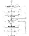
- FIG. 6 is a diagram showing the first half of a control flow in which the upper control unit 8 controls traveling of the plurality of movable units 3.
- FIG. 7 is a diagram showing the second half of the control flow in which the upper control unit 8 controls the traveling of the plurality of movable units 3.
- the traveling path includes a branch road, a circuit, and the like, and the traveling of the plurality of movable portions 3 is controlled in parallel.
- step S1 of FIG. 6 the upper control unit 8 executes initial processing. Specifically, the upper control unit 8 first acquires information regarding the type of work and the content of the work to be performed. Next, the power transmission control unit 81 activates the function of the power transmission regulation unit 24 as a power supply unit and activates each movable unit 3. Next, the traveling control unit 82 transmits a position request signal to each movable unit 3, receives a current position signal from each movable unit 3, and recognizes the current position of each movable unit 3.
- the traveling control unit 82 sets and transmits a traveling command for each movable unit 3 based on the content of the work performed on the work.
- the movable portion 3 travels toward the target position according to the travel command.
- the movable unit 3 that has reached the target position returns a target arrival signal.
- the traveling control unit 82 investigates whether or not the target arrival signal has been received. When the target reaching signal of any of the movable parts 3 is received, execution of the control flow is branched to step S4.
- step S4 after the work of the work robot at the target position is completed, the traveling control unit 82 sets a new traveling command for the movable unit 3 concerned. After that, the execution of the control flow is returned to step S2. In step S2 again, the traveling control unit 82 transmits a new traveling command to the movable unit 3 concerned. If the target reaching signal is not received in step S3, execution of the control flow proceeds to step S11.
- step S11 the power transmission control unit 81 investigates whether or not there is a start of power transmission restriction by the power transmission restriction unit 24 in any of the section units 21. If there is, the traveling control unit 82 prohibits the entry into the relevant section unit 21 in step S12. In the next step S13, the traveling control unit 82 corrects the traveling command so that the movable unit 3 does not enter the section unit 21 that cannot enter. For example, the traveling control unit 82 delays the arrival time by setting a detour, or resets the target position before the inaccessible section unit 21. The correction of the travel command is often executed by some of the movable parts 3, and may not be corrected in some cases.
- the traveling control unit 82 confirms the state of each movable unit 3. That is, the traveling control unit 82 transmits a state confirmation signal to each movable unit 3 and waits for the reception of the operating signal. In the next step S15, the traveling control unit 82 can recognize the movable unit 3 that has not responded to the operation signal as the stopped movable unit 3.
- the traveling control unit 82 executes the control flow in either step S16 or step S21 (see FIG. 7) depending on whether or not the movable part 3 is stopped.
- step S16 when there is the movable portion 3 that is stopped, the traveling control unit 82 stores the movable portion 3 that is stopped and temporarily excludes it from the traveling control targets.
- the movable part 3 which is stopped is located in the section unit 21 where the power transmission regulation is started or is in the middle of approach.
- step S16 After execution of step S16, if there is no movable part 3 stopped in step S15, and if there is no start of power transmission regulation in step S11, execution of the control flow proceeds to step S21 of FIG. 7.
- step S21 the power transmission control unit 81 investigates whether or not the power transmission regulation unit 24 has finished the power transmission regulation in any of the section units 21.
- step S22 the traveling control unit 82 changes the section unit 21, which has been prohibited from entering due to power transmission restriction, to enter (cancellation of entering).
- step S23 the traveling control unit 82 corrects the traveling command of the movable unit 3 in consideration of the section unit 21 that has been changed to be enterable. For example, the traveling control unit 82 corrects the traveling command of the movable unit 3 which arrives earlier by traveling in the section unit 21. Further, for example, the traveling control unit 82 restarts traveling of the movable unit 3 that has stopped before the section unit 21 in question.
- the correction of the travel command is often executed by some of the movable parts 3, and may not be corrected in some cases.
- the traveling control unit 82 can appropriately correct the traveling commands of the plurality of movable units 3 in response to changes in the situation of power transmission regulation.
- step S31 the traveling control unit 82 investigates whether or not there is a response of the in-operation signal from the movable unit 3 which is stopped. If there is, the traveling control unit 82 transmits a position request signal to the movable unit 3 in step S32. In response to this, the movable part 3 returns a current position signal.
- step S33 the traveling control unit 82 returns the movable unit 3 concerned to the subject of traveling control and sets a new traveling command based on the current position.
- step S33 execution of the control flow is returned to step S2.
- step S2 the traveling control unit 82 transmits the corrected traveling command (see steps S13 and S23) and the new traveling command (step S33) to the movable unit 3 concerned. Thereafter, the control flow is repeatedly executed, and the work to be applied to the work is advanced.
- the power transmission regulation unit 24 regulates the power supplied by the power transmission unit 29 to be equal to or lower than a specified level.
- the voltage generated in the power transmission unit 29 of the fixed unit 2 and the voltage generated in the power reception unit 36 of the movable unit 3 are suppressed to be lower than in the normal time, so that the operator can be reliably protected.
- the movable portion 3 can be downsized.
- the protective cover 5, the proximity sensor 6, and the power transmission restrictor 24 are provided as a set in each of all the section units 21, but the present invention is not limited to this. That is, the protection cover 5, the approach sensing unit 6, and the power transmission regulation unit 24 are provided only in a part of the plurality of section units 21, and the protection cover 5 and the approach sensing unit 6 are not attached in the remaining section units 21, A power supply unit that replaces the power transmission regulation unit 24 may be provided. This reduces the cost of the section unit 21 that does not require operator protection.
- the protective cover 5, the proximity sensing unit 6, and the power transmission regulation unit 24 may be provided for two or more adjacent section units 21. According to this, the required number of the protective cover 5, the approach sensing unit 6, and the power transmission regulation unit 24 is reduced, so that the cost is reduced.
- the proximity sensor 6 may be other than the open / close sensor described in the embodiment.
- a human sensor that detects an operator using infrared rays or the like can be used.
- the protection cover 5 can be omitted.
- the traveling drive unit 3C is not limited to the moving coil of the linear motor, and may be, for example, a general motor that rotationally drives traveling wheels.
- the contactless power supply method can be selected separately from the drive method of the traveling drive unit 3C. Therefore, the power transmission unit 29 and the power reception unit 36 are not limited to the coils, and may be, for example, an electrostatic coupling method using an electrode plate. Furthermore, instead of wireless communication between the upper control unit 8 and the movable unit 3, wired communication using a flexible cable may be used. The embodiment can be variously modified and applied in addition to the above.
- traveling device 1 of the embodiment can also be used as a conveying device that conveys only products and equipment, the traveling device 1 is not limited to the manufacturing industry and can be used in various industrial fields such as logistics.
- Traveling device 2 Fixed part 21: Section unit 24: Power transmission regulation part 25: Magnet 26: Rail part 27: Linear scale 28: Running rail 29: Power transmission part 3: Moving part 35: Position detection part 36: Power reception part 3A : Wireless communication unit 3B: Linear control unit 3C: Travel drive unit 5: Protective cover 6: Approach detection unit 8: Upper control unit 81: Power transmission control unit 82: Travel control unit 83: Wireless communication unit
Landscapes
- Engineering & Computer Science (AREA)
- Power Engineering (AREA)
- Mechanical Engineering (AREA)
- Transportation (AREA)
- Sustainable Energy (AREA)
- Life Sciences & Earth Sciences (AREA)
- Sustainable Development (AREA)
- Physics & Mathematics (AREA)
- Electromagnetism (AREA)
- Current-Collector Devices For Electrically Propelled Vehicles (AREA)
- Non-Mechanical Conveyors (AREA)
- Control Of Vehicles With Linear Motors And Vehicles That Are Magnetically Levitated (AREA)
- Control Of Linear Motors (AREA)
Abstract
走行装置は、走行路が形成された固定部と、前記固定部に設けられ、電力を供給する送電部と、前記走行路に沿って走行可能な可動部と、前記可動部に設けられ、前記送電部から非接触で前記電力を受け取る受電部と、前記可動部に設けられ、前記受電部が受け取った前記電力で動作して、前記可動部を駆動する走行駆動部と、前記固定部にオペレータが接近したことを感知する接近感知部と、前記接近感知部が前記固定部への前記オペレータの接近を感知した場合に、前記送電部が供給する前記電力を規定のレベル以下に規制する送電規制部と、を備える。
Description
本明細書は、固定部に形成された走行路に沿って走行可能な可動部を備える走行装置に関し、より詳細には、固定部から可動部に非接触給電を行う走行装置に関する。
近年、生産や物流の自動化および省力化の要請を受けて、無人走行が可能な走行装置の普及が進んでいる。走行装置は、走行路が形成された固定部、および走行路に沿って走行可能な可動部を備える。多くの走行装置は、製品や器材を積載して搬送する搬送装置の用途に適用される。走行装置の駆動形態として、モータによる車輪の回転駆動や、リニアモータによる推進力の発生などが用いられる。また、走行する可動部に給電するために非接触給電の技術を組み合わせた構成も用いられる。非接触給電される走行装置の一技術例が特許文献1に開示されている。
特許文献1に開示された仕分け設備は、走行経路と、走行台車と、走行経路に沿う誘導線路と、走行台車に設けられて誘導線路から非接触給電されるコイルと、を備える。そして、走行経路を導電部材で形成するとともに、走行台車の車輪を導電性車輪としている。これによれば、車輪に発生する電荷は、導電性車輪から走行経路に逃され、静電気の発生を防止できる、とされている。
ところで、特許文献1の技術では、導電性車輪が回転するため、十分な接地が確保されているとは言い難い。このため、確実な接地を目的として、可動部にメカ的な接地構造、例えば摺動ブラシを設ける対策が考えられる。しかしながら、この対策では、接地構造の摩耗に対するメンテナンスが必要となる。また、可動部のケースが確実に接地されていても、非接触で受電するコイルやその後段の電気回路には高い電圧が発生する。したがって、オペレータを保護するために、空間距離や沿面距離を確保することが必要となり、可動部が大型化する。
本明細書では、オペレータを確実に保護しつつ可動部を小型化することができる走行装置を提供することを解決すべき課題とする。
本明細書は、走行路が形成された固定部と、前記固定部に設けられ、電力を供給する送電部と、前記走行路に沿って走行可能な可動部と、前記可動部に設けられ、前記送電部から非接触で前記電力を受け取る受電部と、前記可動部に設けられ、前記受電部が受け取った前記電力で動作して、前記可動部を駆動する走行駆動部と、前記固定部にオペレータが接近したことを感知する接近感知部と、前記接近感知部が前記固定部への前記オペレータの接近を感知した場合に、前記送電部が供給する前記電力を規定のレベル以下に規制する送電規制部と、を備える走行装置を開示する。
本明細書で開示する走行装置によれば、固定部にオペレータが接近したことが感知されると、送電規制部は、送電部が供給する電力を規定のレベル以下に規制する。これにより、固定部の送電部で発生する電圧、および可動部の受電部で発生する電圧が通常時よりも低く抑制されるので、オペレータを確実に保護することができる。また、オペレータを確実に保護するために大きな空間距離や沿面距離を確保する必要が無くなるので、可動部を小型化することができる。
1.実施形態の走行装置1の装置構成
実施形態の走行装置1の装置構成について、図1~図4を参考にして説明する。図1は、実施形態の走行装置1の装置構成を模式的に示す平面図である。走行装置1は、固定部2、送電部29、可動部3、受電部36、走行駆動部3C、保護カバー5、接近感知部6、送電規制部24、および走行制御部82(図5参照)などで構成される。図2は、固定部2の一部および可動部3の構成を示す斜視図であり、一部の部材が省略されている。ここで、可動部3の水平走行方向をX方向、X方向に直角な水平方向をY方向、鉛直方向をZ方向とする。図3は、固定部2をY-Z平面で切った断面図である。図4は、X方向から見た可動部4の側面図であり、一部の部材が省略されている。
実施形態の走行装置1の装置構成について、図1~図4を参考にして説明する。図1は、実施形態の走行装置1の装置構成を模式的に示す平面図である。走行装置1は、固定部2、送電部29、可動部3、受電部36、走行駆動部3C、保護カバー5、接近感知部6、送電規制部24、および走行制御部82(図5参照)などで構成される。図2は、固定部2の一部および可動部3の構成を示す斜視図であり、一部の部材が省略されている。ここで、可動部3の水平走行方向をX方向、X方向に直角な水平方向をY方向、鉛直方向をZ方向とする。図3は、固定部2をY-Z平面で切った断面図である。図4は、X方向から見た可動部4の側面図であり、一部の部材が省略されている。
図1に示されるように、固定部2は、複数の区間ユニット21が連結されて構成される。図には4つの区間ユニット21が示されており、4番目の区間ユニット21の途中以降(図1の下側)は省略されている。区間ユニット21は、図示される直線ユニット以外に、曲線ユニットや、Y字形状の分岐ユニットを含む。固定部2の各区間ユニット21には、走行路が形成される。複数の区間ユニット21が組み合わせられることで、走行路は長く連なって、直線路や曲線路、分岐路や周回路などが形成される。また、連結順序が変更されることで、走行路の形状も変更される。さらに、固定部2は、区間ユニット21の増設により延長可能となっている。
可動部3は、固定部2に装架され、走行路に沿って走行する。可動部3のX方向の長さは、区間ユニット21の長さよりも小さめとされている。可動部3は、その上面の作業台32にワークを載置できるように形成されている。走行装置1は、複数の可動部3を備える構成とすることができる。複数の可動部3は、走行制御部82からの制御にしたがって走行し、衝突が回避される。
保護カバー5は、図1では便宜的に破線で示されており、区間ユニット21の各々に設けられる。保護カバー5のX方向に長い一辺51は、一対の蝶番52を用いて区間ユニット21の一方の側縁に開閉可能に取り付けられる。保護カバー5のX方向に長い他辺53は、区間ユニット21の他方の側縁に上から接する。保護カバー5は、透明な樹脂を用いて、上方に膨らむ形状に形成されている。保護カバー5は、通常時に閉じており、固定部2および走行してくる可動部3を覆うことで、オペレータを保護する。
保護カバー5の他辺53寄りに、矩形の切り欠き窓54が形成されている。切り欠き窓54を通して、可動部3の作業台32にワークを載せたり降ろしたりする積み下ろし作業が行われる。さらに、切り欠き窓54を通して、作業台32上のワークに加工作業や組立作業が施される。これらの作業は、図略の作業ロボットによって実施される。
接近感知部6は、区間ユニット21の各々に設けられる。接近感知部6は、保護カバー5の他辺53に近接して配置される。接近感知部6として、通常時に閉じている保護カバー5の開操作を検出する開閉センサが用いられる。つまり、接近感知部6は、オペレータが保護カバー5を開ける操作を検出することによって、固定部2へのオペレータの接近を感知する。
固定部2を構成する区間ユニット21の各々は、相互に類似した装置構成を有する。したがって、以降の説明では、1つの区間ユニット21の構成を固定部2の構成として説明する。図2および図3に示されるように、固定部2は、底板22および一対の側板23を主要な構造材として構成され、上方に開口している。固定部2は、図3に示されるように、Y方向に左右対称の構造を有する。底板22は、下方に開口する薄い箱型形状をなしている。底板22の下側に、送電規制部24が取り付けられる。送電規制部24は、通常時には非接触給電を行う電源部として機能する。
一対の側板23は、底板22の上面に、離隔平行して立設される。一対の側板23の内面に、複数の磁石25が設けられる。磁石25の各々は、Z方向に長い板状に形成されている。複数の磁石25は、向かい合う内側でX方向にN極およびS極が交互に現れるように配置される。側板23の上面に、X方向に延びるレール部26が設けられる。レール部26の内側の側面は、V字形状に形成されている。一方のレール部26(図3の左側)の上面には、X方向に延びるリニアスケール27が取り付けられる。
また、底板22の上側のY方向の中央に、走行レール28が設けられる。走行レール28は、X方向に延びるとともに、上方に開口する溝形状に形成される。走行レール28および一対のレール部26は、可動部3が走行する走行路を構成する。
一対の側板23の下部は、内側に屈折して走行レール28に接近している。一対の側板23の各々の下部の上面に、送電部29が配設される。一対の送電部29の各々は、X方向に延びる送電コイルとされている。送電コイルは、巻線2Aおよびコア2Bで構成される。コア2Bは、フェライトや電磁鋼板などの磁性材料を用いて形成される。コア2BをY―Z平面で切った断面は、上方に開口するE字形状になっている。送電部29は、送電規制部24から電源供給され、後述する受電部36に非接触で電力を供給する。
図2および図4に示されるように、可動部3は、本体部31および作業台32で構成される。本体部31は、X方向に長い箱型形状に形成され、内部には後述する様々な部材が配設される。作業台32は、矩形の薄板状に形成され、本体部31の上側に固定される。作業台32には、ワークの底面の突起が係入するための丸穴が刻設されている。これにより、ワークは、安定して載置され、可動部3の走行中でも揺れたりずれたりしない。
本体部31の上部寄りに、溝ローラ33が設けられる。溝ローラ33は、X方向に3個並ぶとともにY方向に2組で合計6個設けられる。溝ローラ33は、固定部2のレール部26のV字形状の部位に内側から摺動する。本体部31の下面に、走行ローラ34が設けられる。走行ローラ34は、Y方向に並んだ2個を1組とし、X方向に離隔して複数組設けられる。走行ローラ34は、固定部2の走行レール28の内側の側面に摺動する。溝ローラ33および走行ローラ34により、可動部3の走行が可能となっている。
本体部31の上部のY方向の一端に位置検出部35が設けられる。位置検出部35は、固定部2のリニアスケール27に対向配置される。位置検出部35は、リニアスケール27の目盛りを検出して、可動部3の走行路上の現在位置を検出する。位置検出部35およびリニアスケール27の検出方式として、光学的な検出方式や、電磁誘導を用いた検出方式を例示でき、これらに限定されない。
本体部31の下面の走行ローラ34のY方向の外側に、一対の受電部36が設けられている。一対の受電部36の各々は、X方向に延びる受電コイルとされている。受電コイルは、巻線37およびコア38で構成される。コア38は、送電部29のコア2Bと同じ材料を用いて形成される。コア38をY―Z平面で切った断面は、下方に開口するE字形状になっている。
受電部36は、可動部3の現在位置に依存せずに、いずれかの固定部2の送電部29と対向配置される。これにより、送電部のコア2Bおよび受電部36のコア38は、接近して磁気結合し、共同して周回磁路を形成する。したがって、電磁結合方式の非接触給電により、受電部36は、送電部29から電力を受け取ることができる。
本体部31の中央寄りに、受電回路39、無線通信部3A、およびリニア制御部3Bが設けられる。さらに、本体部31の中間高さのY方向の両側の側面に、一対の走行駆動部3Cが設けられる。受電回路39は、受電部36が受け取った電力を変成して、無線通信部3Aおよびリニア制御部3Bに電源供給する。
リニア制御部3Bは、走行駆動部3Cに供給する電力を制御する。走行駆動部3Cには、ムービングコイルが用いられる。ムービングコイルは、巻線3Dおよびコア3Eで構成される。ムービングコイルは、固定部2の磁石25に対向配置される。巻線3Dに電流が流れると、コア3Eに磁極が誘起されて、磁石25との間に磁力が発生する。したがって、走行駆動部3Cと磁石25の組み合わせによりリニアモータが構成され、可動部3のX軸方向の推進力が生成される。なお、可動部3に磁石を設け、固定部2にコイルを設けるリニアモータと比較して、実施形態のリニアモータは、低コスト、走行制御が容易などのメリットがある。
2.実施形態の走行装置1の制御の構成
次に、実施形態の走行装置1の制御の構成について説明する。図5は、実施形態の走行装置1の制御の構成および電源供給経路を説明するブロック図である。図示されるように、走行装置1は、上位制御部8を含んで構成される。上位制御部8は、ワークに実施する前述の各種作業を制御するとともに、これに合わせて複数の可動部3の走行を制御し、さらには可動部3への非接触給電を制御する。上位制御部8は、送電制御部81、走行制御部82、および無線通信部83を含む。
次に、実施形態の走行装置1の制御の構成について説明する。図5は、実施形態の走行装置1の制御の構成および電源供給経路を説明するブロック図である。図示されるように、走行装置1は、上位制御部8を含んで構成される。上位制御部8は、ワークに実施する前述の各種作業を制御するとともに、これに合わせて複数の可動部3の走行を制御し、さらには可動部3への非接触給電を制御する。上位制御部8は、送電制御部81、走行制御部82、および無線通信部83を含む。
また、前述したように、固定部2の区間ユニット21の各々は、送電規制部24、送電部29、および接近感知部6を備える。送電規制部24の各々は、上位制御部8の送電制御部81と通信接続される。送電規制部24は、送電制御部81からの送電指令にしたがって動作し、送電部29に電源供給する。この電源として、送電部29の周波数特性に見合う交流電源を用いることができる。
送電規制部24は、接近感知部6が固定部2へのオペレータの接近を感知した場合に、送電部29への電源供給を自動的に停止する。これにより、送電部29から受電部36への非接触の電力供給(図中の矢印P)が停止される。なお、送電規制部24は、送電部29への電源供給を停止せず、電源供給を規定のレベル以下に規制してもよい。この場合、送電部29から受電部36への電力供給も、規定のレベル以下に低下する。
上述した送電規制において、接近感知部6による感知以降にソフトウェア処理は介在せず、ハード的に速やかに規制が実現される。例えば、電磁リレー装置によって送電規制部24内の電路が遮断される。このため、保護カバー5が開いた当該の区間ユニット21で発生していた電圧は、速やかに消失し、または顕著に減少する。また、当該の区間ユニット21内に可動部3が位置していた場合、非接触給電が行われなくなり、または受電部36の受電電力が顕著に減少する。このため、可動部3は停止し、かつ可動部3で発生する電圧は、速やかに顕著に減少する。したがって、保護カバー5が開いていても、確実にオペレータが保護される。
また、保護カバー5が閉じられて、接近感知部6の感知状態が解消されたとき、送電規制部24は、送電部29への電源供給を自動的に再開する。これにより、非接触給電が自動的に再開される。送電規制部24は、送電規制の開始および終了を送電制御部81に通知する。走行制御部82は、区間ユニット21の各々における送電規制の開始および終了の情報を共有する。
また、前述したように、可動部3は、位置検出部35、受電部36、受電回路39、無線通信部3A、リニア制御部3B、および走行駆動部3Cを含む。無線通信部3Aは、上位制御部8の無線通信部83と、双方向の信号授受が可能な無線通信を行う。上位側の無線通信部83は、複数の可動部3の無線通信部3Aに対して、1:N方式の無線通信を行うように構成されている(図5のWL参照)。
走行制御部82は、ワークに施す作業を円滑に進めるために、各可動部3の位置を制御する走行指令を発する。走行指令は、例えば目標位置、走行経路、および到達時刻で表される。走行指令は、無線通信部83から各可動部3の無線通信部3Aに送信される。無線通信部3Aは、受信した走行指令をリニア制御部3Bに伝える。リニア制御部3Bは、走行指令に基づいて、走行駆動部3Cに供給する電力を制御する。このとき、リニア制御部3Bは、位置検出部35が検出した現在位置を参照して、PID制御等を行う。さらに、リニア制御部3Bは、目標位置に到達したことを表す目標到達信号を無線通信部3Aから無線通信部83に返信させる。
ここで、可動部3は、バッテリを備えていないので、非接触給電が規制されると走行用電源が確保されなくなる。このとき、受電部36(受電コイル)は、走行を妨げる電磁ブレーキとして作用する。これにより、可動部3は、短い惰性走行距離で停止する。また、無線通信部3Aおよびリニア制御部3Bも停止する。したがって、可動部3の現在位置は不明となる。また、既に受信済みの走行指令は意味のないものとなる。
また、走行制御部82は、送電制御部81から給電停止した区間ユニット21の情報を受け取ったとき、無線通信部83から全部の可動部3に状態確認指令を送信させる。動作中の可動部3は、状態確認指令を受け取ると、動作中信号を応答する。一方、停止している可動部3は、動作中信号を応答することができない。したがって、走行制御部82は、停止している可動部3を判定できる。そして、走行制御部82は、動作中の(停止していない)可動部3が給電停止した区間ユニット21に進入しないように制御する。
この後、停止している可動部3に対する非接触給電が再開されると、当該の可動部3は、復帰直後に動作中信号を無線通信部83に応答する。これにより、走行制御部82は、停止していた可動部3の復帰を認識する。次に、走行制御部82は、無線通信部83から当該の可動部3へと、位置要求信号を送信させる。これに応じて、当該の可動部3は、現在位置信号を返信する。走行制御部82は、現在位置信号を受信することにより、不明になっていた当該の可動部3の現在位置を認識する。この後、走行制御部82は、新しい走行指令を設定して、当該の可動部3の走行を再開させる。
3.実施形態の走行装置1の動作
次に、実施形態の走行装置1の動作について説明する。図6は、上位制御部8が複数の可動部3の走行を制御する制御フローの前半を示す図である。また、図7は、上位制御部8が複数の可動部3の走行を制御する制御フローの後半を示す図である。以降では、走行路が分岐路や周回路等を含み、複数の可動部3の走行を並行して制御する場合について説明する。
次に、実施形態の走行装置1の動作について説明する。図6は、上位制御部8が複数の可動部3の走行を制御する制御フローの前半を示す図である。また、図7は、上位制御部8が複数の可動部3の走行を制御する制御フローの後半を示す図である。以降では、走行路が分岐路や周回路等を含み、複数の可動部3の走行を並行して制御する場合について説明する。
図6のステップS1で、上位制御部8はイニシャル処理を実行する。具体的に、上位制御部8は、まず、ワークの種類および施す作業の内容に関する情報を取得する。次に、送電制御部81は、送電規制部24の電源部としての機能を立ち上げ、各可動部3を起動する。次に、走行制御部82は、各可動部3に位置要求信号を送信して、各可動部3から現在位置信号を受信し、各可動部3の現在位置を認識する。
次のステップS2で、走行制御部82は、ワークに施す作業の内容に基づいて各可動部3の走行指令を設定し、送信する。可動部3は、走行指令にしたがい目標位置をめざして走行する。目標位置に到達した可動部3は、目標到達信号を返信する。次のステップS3で、走行制御部82は、目標到達信号を受信したか否か調査する。いずれかの可動部3の目標到達信号を受信している場合に、制御フローの実行は、ステップS4に分岐される。
ステップS4で、目標位置における作業ロボットの作業が終了した後、走行制御部82は、当該の可動部3について新しい走行指令を設定する。この後、制御フローの実行は、ステップS2に戻される。再度のステップS2で、走行制御部82は、新しい走行指令を当該の可動部3に送信する。ステップS3で、目標到達信号が受信されていない場合、制御フローの実行は、ステップS11に進められる。
ステップS11で、送電制御部81は、いずれかの区間ユニット21において、送電規制部24による送電規制の開始が有ったか否かを調査する。有った場合のステップS12で、走行制御部82は、当該の区間ユニット21への進入を不可とする。次のステップS13で、走行制御部82は、可動部3が進入不可の区間ユニット21に進入しないよう走行指令を修正する。例えば、走行制御部82は、迂回路を設定して到達時刻を遅らせたり、進入不可の区間ユニット21の手前に目標位置を再設定したりする。走行指令の修正は、一部の可動部3で実行される場合が多く、修正が行われない場合もある。
また、送電規制が開始されたことで、可動部3が停止する可能性が生じている。このため、次のステップS14で、走行制御部82は、各可動部3の状態を確認する。すなわち、走行制御部82は、各可動部3に状態確認信号を送信して、動作中信号の受信を待つ。次のステップS15で、走行制御部82は、動作中信号を応答しなかった可動部3を、停止している可動部3と認識できる。
走行制御部82は、停止している可動部3の有無に応じて、制御フローの実行をステップS16またはステップS21(図7参照)のいずれかとする。停止している可動部3が有る場合のステップS16で、走行制御部82は、停止している可動部3を記憶し、一時的に走行制御の対象外とする。なお、停止している可動部3は、送電規制が開始された区間ユニット21内に位置し、または進入途中であった、と想定される。
ステップS16の実行後、ステップS15で停止している可動部3が無い場合、および、ステップS11で送電規制の開始が無かった場合、制御フローの実行は、図7のステップS21に進められる。ステップS21で、送電制御部81は、いずれかの区間ユニット21において、送電規制部24による送電規制の終了が有ったか否かを調査する。
有った場合のステップS22で、走行制御部82は、送電規制されて進入不可とされていた区間ユニット21を進入可に変更する(進入不可の解消)。次のステップS23で、走行制御部82は、進入可に変更された当該の区間ユニット21を考慮して、可動部3の走行指令を修正する。例えば、走行制御部82は、当該の区間ユニット21を走行することによって到達時刻が早くなる可動部3の走行指令を修正する。また例えば、走行制御部82は、当該の区間ユニット21の手前で停止していた可動部3の走行を再開させる。走行指令の修正は、一部の可動部3で実行される場合が多く、修正が行われない場合もある。
なお、複数の区間ユニット21で送電規制が行われる可能性が有る。また、或る区間ユニット21における送電規制の開始と、別の区間ユニット21における送電規制の終了が、同時に発生することもある。走行制御部82は、送電規制の状況変化に対応して、複数の可動部3の走行指令を的確に修正することが可能である。
ステップS23の実行後、および、ステップS21で送電規制の終了が無かった場合、制御フローの実行は、ステップS31に進められる。ステップS31で、走行制御部82は、停止している可動部3からの動作中信号の応答の有無を調査する。有った場合のステップS32で、走行制御部82は、当該の可動部3に位置要求信号を送信する。これに応じて、当該の可動部3は、現在位置信号を返信する。
次のステップS33で、走行制御部82は、当該の可動部3を走行制御の対象に戻し、現在位置に基づいて新しい走行指令を設定する。ステップS33の実行後、および、ステップS31で動作中信号が無かった場合、制御フローの実行は、ステップS2に戻される。ステップS2で、走行制御部82は、修正した走行指令(ステップS13、ステップS23参照)および新しい走行指令(ステップS33)を当該の可動部3に送信する。以下、制御フローが繰り返して実行され、ワークに施す作業が進められてゆく。
実施形態の走行装置1によれば、固定部2にオペレータが接近したことが感知されると、送電規制部24は、送電部29が供給する電力を規定のレベル以下に規制する。これにより、固定部2の送電部29で発生する電圧、および可動部3の受電部36で発生する電圧が通常時よりも低く抑制されるので、オペレータを確実に保護することができる。また、オペレータを確実に保護するために大きな空間距離や沿面距離を確保する必要が無くなるので、可動部3を小型化することができる。
4.実施形態の変形および応用
なお、実施形態において、全部の区間ユニット21の各々に保護カバー5、接近感知部6、および送電規制部24がセットで設けられるが、これに限定されない。つまり、複数の区間ユニット21の一部にだけ保護カバー5、接近感知部6、および送電規制部24が設けられ、残りの区間ユニット21で保護カバー5および接近感知部6は不付きとされ、送電規制部24に代わる電源部が設けられてもよい。これによれば、オペレータの保護を必要としない区間ユニット21のコストが軽減される。
なお、実施形態において、全部の区間ユニット21の各々に保護カバー5、接近感知部6、および送電規制部24がセットで設けられるが、これに限定されない。つまり、複数の区間ユニット21の一部にだけ保護カバー5、接近感知部6、および送電規制部24が設けられ、残りの区間ユニット21で保護カバー5および接近感知部6は不付きとされ、送電規制部24に代わる電源部が設けられてもよい。これによれば、オペレータの保護を必要としない区間ユニット21のコストが軽減される。
また、隣接する二つ以上の区間ユニット21を対象として、保護カバー5、接近感知部6、および送電規制部24が設けられてもよい。これによれば、保護カバー5、接近感知部6、および送電規制部24の必要数が減少するので、コストが軽減される。
さらに、接近感知部6は、実施形態で説明した開閉センサ以外でもよい。例えば、赤外線等を用いてオペレータを検出する人感知センサを用いることができる。これによれば、保護カバー5を省略することも可能となる。また、走行駆動部3Cは、リニアモータのムービンングコイルに限定されず、例えば、走行車輪を回転駆動する一般的なモータであってもよい。
また、非接触給電の方式は、走行駆動部3Cの駆動方式と切り離して選定することができる。したがって、送電部29および受電部36は、コイルに限定されず、例えば、電極板を用いる静電結合方式とすることも可能である。さらに、上位制御部8と可動部3との間の無線通信に代え、可撓性ケーブルによる有線通信を用いてもよい。実施形態は、その他にも様々な変形や応用が可能である。
実施形態の走行装置1は、製品や器材の搬送のみを行う搬送装置として利用することもできるので、製造業に限定されず、物流を始めとするさまざまな産業分野での利用が可能である。
1:走行装置 2:固定部 21:区間ユニット 24:送電規制部 25:磁石 26:レール部 27:リニアスケール 28:走行レール 29:送電部 3:可動部 35:位置検出部 36:受電部 3A:無線通信部 3B:リニア制御部 3C:走行駆動部 5:保護カバー 6:接近感知部 8:上位制御部 81:送電制御部 82:走行制御部 83:無線通信部
Claims (12)
- 走行路が形成された固定部と、
前記固定部に設けられ、電力を供給する送電部と、
前記走行路に沿って走行可能な可動部と、
前記可動部に設けられ、前記送電部から非接触で前記電力を受け取る受電部と、
前記可動部に設けられ、前記受電部が受け取った前記電力で動作して、前記可動部を駆動する走行駆動部と、
前記固定部にオペレータが接近したことを感知する接近感知部と、
前記接近感知部が前記固定部への前記オペレータの接近を感知した場合に、前記送電部が供給する前記電力を規定のレベル以下に規制する送電規制部と、
を備える走行装置。 - 前記送電規制部は、前記送電部からの電力供給を停止する、請求項1に記載の走行装置。
- 前記固定部は、複数の区間ユニットが連結されて構成され、
複数の前記区間ユニットの少なくとも一部に、それぞれ前記接近感知部および前記送電規制部が設けられ、あるいは、隣接する二つ以上の前記区間ユニットを対象として、前記接近感知部および前記送電規制部が設けられる、請求項1または2に記載の走行装置。 - 前記固定部は、前記区間ユニットの増設により延長可能である、請求項3に記載の走行装置。
- 前記走行駆動部は、ムービングコイルであって、前記固定部に並んで設けられた磁石と組み合わせられてリニアモータが構成される、請求項1~4のいずれか一項に記載の走行装置。
- 前記走行装置は、前記固定部および前記可動部の少なくとも一部を覆うことができ、かつ開閉可能な保護カバーをさらに備え、
前記接近感知部は、通常時に閉じている前記保護カバーの開操作の検出により、前記固定部への前記オペレータの接近を感知する、請求項1~5のいずれか一項に記載の走行装置。 - 前記可動部の走行を制御する走行制御部をさらに備える、請求項1~6のいずれか一項に記載の走行装置。
- 前記走行制御部は、前記接近感知部および前記送電規制部の少なくとも一方の動作状態を取得して、前記可動部の走行を制御する、請求項7に記載の走行装置。
- 前記固定部は、複数の区間ユニットが連結されて構成され、
複数の前記区間ユニットの少なくとも一部に、それぞれ前記接近感知部および前記送電規制部が設けられ、あるいは、隣接する二つ以上の前記区間ユニットを対象として、前記接近感知部および前記送電規制部が設けられており、
前記可動部は、前記送電規制部の動作している前記区間ユニットでは停止し、
前記走行制御部は、停止していない前記可動部が前記送電規制の行われている前記区間ユニットに進入しないように制御する、請求項7または8に記載の走行装置。 - 前記可動部および前記走行制御部は、双方向の信号授受が可能な通信部を有し、
前記可動部は、前記送電規制部の動作していない前記区間ユニットでは前記走行制御部からの通信に応答し、前記送電規制部の動作している前記区間ユニットでは前記走行制御部からの通信に応答せず、
前記走行制御部は、通信に対する前記可動部からの応答の有無に基づいて停止している前記可動部を判定する、請求項7~9のいずれか一項に記載の走行装置。 - 前記可動部は、前記走行路における現在位置を検出する位置検出部を有し、
前記走行制御部は、停止していた前記可動部からの応答を受信したときに、前記可動部の前記現在位置を取得してから走行の再開を制御する、請求項10に記載の走行装置。 - 前記送電部は送電コイルであり、前記受電部は受電コイルである、請求項1~11のいずれか一項に記載の走行装置。
Priority Applications (2)
| Application Number | Priority Date | Filing Date | Title |
|---|---|---|---|
| JP2020557401A JP7047127B2 (ja) | 2018-11-22 | 2018-11-22 | 走行装置 |
| PCT/JP2018/043283 WO2020105192A1 (ja) | 2018-11-22 | 2018-11-22 | 走行装置 |
Applications Claiming Priority (1)
| Application Number | Priority Date | Filing Date | Title |
|---|---|---|---|
| PCT/JP2018/043283 WO2020105192A1 (ja) | 2018-11-22 | 2018-11-22 | 走行装置 |
Publications (1)
| Publication Number | Publication Date |
|---|---|
| WO2020105192A1 true WO2020105192A1 (ja) | 2020-05-28 |
Family
ID=70774101
Family Applications (1)
| Application Number | Title | Priority Date | Filing Date |
|---|---|---|---|
| PCT/JP2018/043283 Ceased WO2020105192A1 (ja) | 2018-11-22 | 2018-11-22 | 走行装置 |
Country Status (2)
| Country | Link |
|---|---|
| JP (1) | JP7047127B2 (ja) |
| WO (1) | WO2020105192A1 (ja) |
Cited By (2)
| Publication number | Priority date | Publication date | Assignee | Title |
|---|---|---|---|---|
| EP4071970A1 (en) * | 2021-03-31 | 2022-10-12 | ATS Automation Tooling Systems Inc. | Method and system for wireless communication in a conveyor system |
| WO2024257432A1 (ja) * | 2023-06-14 | 2024-12-19 | 株式会社日立ハイテク | 試料搬送システム、試料搬送キャリア、および試料容器の搬送方法 |
Citations (4)
| Publication number | Priority date | Publication date | Assignee | Title |
|---|---|---|---|---|
| JPH08324790A (ja) * | 1995-06-02 | 1996-12-10 | Daifuku Co Ltd | 仕分け設備 |
| JPH101046A (ja) * | 1996-06-18 | 1998-01-06 | Daifuku Co Ltd | 搬送設備 |
| JP2001122108A (ja) * | 1999-10-28 | 2001-05-08 | Murata Mach Ltd | 有軌道台車システム |
| JP2017070146A (ja) * | 2015-10-01 | 2017-04-06 | ニチユ三菱フォークリフト株式会社 | 無線給電システム |
-
2018
- 2018-11-22 JP JP2020557401A patent/JP7047127B2/ja active Active
- 2018-11-22 WO PCT/JP2018/043283 patent/WO2020105192A1/ja not_active Ceased
Patent Citations (4)
| Publication number | Priority date | Publication date | Assignee | Title |
|---|---|---|---|---|
| JPH08324790A (ja) * | 1995-06-02 | 1996-12-10 | Daifuku Co Ltd | 仕分け設備 |
| JPH101046A (ja) * | 1996-06-18 | 1998-01-06 | Daifuku Co Ltd | 搬送設備 |
| JP2001122108A (ja) * | 1999-10-28 | 2001-05-08 | Murata Mach Ltd | 有軌道台車システム |
| JP2017070146A (ja) * | 2015-10-01 | 2017-04-06 | ニチユ三菱フォークリフト株式会社 | 無線給電システム |
Cited By (3)
| Publication number | Priority date | Publication date | Assignee | Title |
|---|---|---|---|---|
| EP4071970A1 (en) * | 2021-03-31 | 2022-10-12 | ATS Automation Tooling Systems Inc. | Method and system for wireless communication in a conveyor system |
| US12397999B2 (en) | 2021-03-31 | 2025-08-26 | Ats Corporation | Method and system for wireless communication in a conveyor system |
| WO2024257432A1 (ja) * | 2023-06-14 | 2024-12-19 | 株式会社日立ハイテク | 試料搬送システム、試料搬送キャリア、および試料容器の搬送方法 |
Also Published As
| Publication number | Publication date |
|---|---|
| JPWO2020105192A1 (ja) | 2021-10-07 |
| JP7047127B2 (ja) | 2022-04-04 |
Similar Documents
| Publication | Publication Date | Title |
|---|---|---|
| US8319474B2 (en) | Non-contact type power feeder system for mobile object | |
| JP5895631B2 (ja) | 車両給電装置 | |
| CN105468001B (zh) | 一种潜入式agv导航小车及其控制方法 | |
| CN105467998A (zh) | 一种重载举升式agv小车 | |
| JP2014236539A (ja) | 非接触充電用送電装置及び電動車両の走行制御システム | |
| CN108860174A (zh) | 物品输送车 | |
| WO2012153807A1 (ja) | 車両及び非接触給電システム | |
| CN103135548A (zh) | 一种无人搬运小车及其驱动控制系统 | |
| KR20190065645A (ko) | 자율주행 자동차의 드론 도킹 구조 및 이를 이용한 배송 방법 | |
| CN103053092A (zh) | 用于向移动元件提供动力的系统和方法 | |
| JP5040271B2 (ja) | 有軌道搬送装置 | |
| JP5287810B2 (ja) | 走行車システム | |
| JP6619597B2 (ja) | 搬送車システム | |
| JP2016187243A (ja) | 充電システム、充電装置 | |
| US20240217749A1 (en) | Energy transmission in a linear transport system | |
| TW201841815A (zh) | 高架搬運車系統及教學單元 | |
| JP2008197705A (ja) | 搬送台車、停止位置判定方法およびプログラム | |
| JP7047127B2 (ja) | 走行装置 | |
| JP5655700B2 (ja) | 搬送システム | |
| JP6803476B2 (ja) | ワーク搬送システム | |
| JP7083886B2 (ja) | 搬送装置、及び搬送路 | |
| JP7016327B2 (ja) | 搬送システム、及びキャリアの位置を特定する方法 | |
| US20050061195A1 (en) | Conveying device | |
| WO2020241677A1 (ja) | 送電装置および無線電力伝送システム | |
| US11804736B2 (en) | Power transmission device, power reception device, wireless power transmission system, and method for driving power transmission device |
Legal Events
| Date | Code | Title | Description |
|---|---|---|---|
| 121 | Ep: the epo has been informed by wipo that ep was designated in this application |
Ref document number: 18940612 Country of ref document: EP Kind code of ref document: A1 |
|
| ENP | Entry into the national phase |
Ref document number: 2020557401 Country of ref document: JP Kind code of ref document: A |
|
| NENP | Non-entry into the national phase |
Ref country code: DE |
|
| 122 | Ep: pct application non-entry in european phase |
Ref document number: 18940612 Country of ref document: EP Kind code of ref document: A1 |