WO2020105134A1 - 部品実装装置 - Google Patents
部品実装装置Info
- Publication number
- WO2020105134A1 WO2020105134A1 PCT/JP2018/042962 JP2018042962W WO2020105134A1 WO 2020105134 A1 WO2020105134 A1 WO 2020105134A1 JP 2018042962 W JP2018042962 W JP 2018042962W WO 2020105134 A1 WO2020105134 A1 WO 2020105134A1
- Authority
- WO
- WIPO (PCT)
- Prior art keywords
- component
- suction
- target
- correction amount
- limit
- Prior art date
- Legal status (The legal status is an assumption and is not a legal conclusion. Google has not performed a legal analysis and makes no representation as to the accuracy of the status listed.)
- Ceased
Links
Images





Classifications
-
- H—ELECTRICITY
- H05—ELECTRIC TECHNIQUES NOT OTHERWISE PROVIDED FOR
- H05K—PRINTED CIRCUITS; CASINGS OR CONSTRUCTIONAL DETAILS OF ELECTRIC APPARATUS; MANUFACTURE OF ASSEMBLAGES OF ELECTRICAL COMPONENTS
- H05K13/00—Apparatus or processes specially adapted for manufacturing or adjusting assemblages of electric components
- H05K13/04—Mounting of components, e.g. of leadless components
-
- H—ELECTRICITY
- H05—ELECTRIC TECHNIQUES NOT OTHERWISE PROVIDED FOR
- H05K—PRINTED CIRCUITS; CASINGS OR CONSTRUCTIONAL DETAILS OF ELECTRIC APPARATUS; MANUFACTURE OF ASSEMBLAGES OF ELECTRICAL COMPONENTS
- H05K13/00—Apparatus or processes specially adapted for manufacturing or adjusting assemblages of electric components
- H05K13/08—Monitoring manufacture of assemblages
Definitions
- This specification discloses a component mounting apparatus.
- a mounting head suction nozzle
- a mounting head is moved to a pick-up position of an electronic component (component) of a component supply device to suck and pick up a component on the mounting head, and then a printed circuit board (board) is placed.
- a method of mounting a component on a board by moving a mounting head to the mounting position see, for example, Patent Document 1.
- the component mounting apparatus sucks the component on the mounting head
- the component mounting camera moves the mounting head to the imaging position, images the component adsorbed on the mounting head with the component recognition camera, and shifts the position of the component based on the captured image. Recognize.
- the component mounting apparatus corrects the mounting position based on the recognized positional deviation to mount the component, and calculates the take-out position used for the next component taking-out operation based on the recognized positional deviation. Further, the component mounting apparatus determines whether or not the calculated take-out position exceeds the limit position (moving allowable range), and when it determines that the calculated take-out position exceeds the limit position, the subsequent component take-out operation is performed. Try to do it at the limit position.
- the limit position moving allowable range
- the displacement of the component is recognized based on the captured image by moving the suction nozzle to the image capturing position and capturing the image of the component suctioned by the suction nozzle by the image capturing device.
- the position of the component may be displaced due to acceleration or vibration acting on the component when moving the component suctioned by the suction nozzle to the imaging position.
- the positional deviation of the component different from that at the time of suction is recognized based on the captured image, and the pick-up position of the next component is calculated based on the positional deviation, resulting in deterioration of the suction accuracy of the component.
- the main purpose of the present disclosure is to suppress deterioration of suction accuracy of parts.
- the present disclosure has adopted the following means in order to achieve the main purpose described above.
- the component mounting apparatus of the present disclosure is A component mounting device for adsorbing a component supplied by a component supply device and mounting the component on an object, A suction nozzle for sucking the component, A moving device that moves the suction nozzle relative to the component supply device, An image pickup device for picking up an image of a component sucked by the suction nozzle, The suction control that controls the moving device so that the component supplied by the component supply device is sucked by the suction nozzle at the target suction position, and the component sucked by the suction nozzle is imaged at a predetermined imaging position.
- the target suction position is adjusted by the correction amount. And a target suction position updating process for updating the target suction position with a correction amount smaller than the limit when the correction amount corresponding to the position shift amount reaches the limit.
- the control device of the component mounting apparatus includes suction control that controls the component supplied by the component supply device to be sucked by the suction nozzle at the target suction position, and target suction position update processing that updates the target suction position. And execute.
- the target suction position update processing the component sucked by the suction nozzle is imaged at a predetermined image pickup position, and the correction amount according to the amount of displacement of the component recognized based on the imaged image of the component does not reach the limit. In this case, the target suction position is updated with the correction amount.
- the correction amount according to the positional deviation amount reaches the limit
- the target suction position is updated with the correction amount smaller than the limit.
- the component mounting apparatus of the present disclosure when the position of the component that is sucked by the suction nozzle is shifted due to some reason when the component is moved to the image capturing position, a position different from that at the time of suction is determined based on the captured image captured in that state.
- the shift amount may be recognized. Therefore, the component mounting apparatus of the present disclosure updates the target pick-up position with a correction amount smaller than the limit when the correction amount of the target pick-up position derived according to the amount of displacement of the part reaches the limit.
- FIG. 7 is a flowchart illustrating an example of component mounting processing.
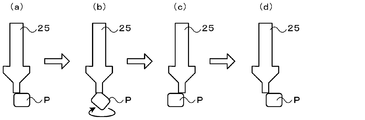
- 6 is an explanatory diagram showing a state in which a component P is sucked and then conveyed onto a substrate S.
- FIG. It is a flow chart which shows an example of target adsorption position renewal processing.
- target adsorption position renewal processing It is explanatory drawing which shows a mode that the adsorption
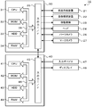
- FIG. 1 is a block diagram showing an outline of the configuration of the component mounting apparatus 10 of this embodiment.
- FIG. 2 is an explanatory diagram showing an electrical connection relationship of the control device 30.
- the left-right direction in FIG. 1 is the X-axis direction
- the front (front side) rear (back) direction is the Y-axis direction
- the up-down direction is the Z-axis direction.
- the component mounting apparatus 10 includes a component supply device 21, a board transfer device 22, a moving mechanism 23, a head 24, a suction nozzle 25, a parts camera 26, a mark camera 27, and a nozzle.
- the stocker 28 and the control device 30 are provided.
- the component supply device 21 supplies the component P to the component supply position.
- the component supply device 21 is configured as a tape feeder that supplies the component P to the component supply position by pulling out the tape in which the component P is accommodated in the accommodating portions formed at predetermined intervals from the reel and feeding the tape by the pitch.
- the tape feeder is detachably attached to a plurality of feeder stands arranged in the left-right direction (X-axis direction) provided in the front part of the base 11 that supports the housing 12.
- the substrate transfer device 22 is provided from the central part to the rear part of the base 11, and carries in, fixes, and carries out the substrate S along the left-right direction (X-axis direction) in the drawing.
- the substrate transfer device 22 has a pair of conveyor belts that are provided at a front and a back with a space therebetween and are bridged in the left and right direction.
- the substrate S is conveyed by a conveyor belt.
- the head 24 sucks the component P supplied to the component supply position and mounts it on the substrate S.
- the head 24 includes a nozzle holder to which the suction nozzle 25 is attachable and detachable, and an elevating device that moves the nozzle holder up and down (moves in the Z-axis direction) together with the suction nozzle 25.
- the suction nozzle 25 sucks the component P by the negative pressure supplied to and discharged from the suction port.
- the moving mechanism 23 moves the head 24 in the XY directions.
- the moving mechanism 23 can be configured by, for example, a ball screw mechanism.
- the parts camera 26 is provided between the component supply device 21 of the base 11 and the board transfer device 22, and images the component P sucked by the suction nozzle 25 from below.
- the mark camera 27 is provided on the head 24 and images the positioning reference mark attached to the substrate S from above.
- the nozzle stocker 28 is provided adjacent to the parts camera 26 and stocks a plurality of replacement suction nozzles 25.
- the control device 30 includes a CPU 31, a ROM 32, a HDD 33, a RAM 34, and an input / output interface 35. These are electrically connected via the bus 36.
- An image signal from the parts camera 26 and the mark camera 27, a detection signal from a position sensor that detects each position of the suction nozzle 25 in the X direction, the Y direction, and the Z direction is sent to the control device 30 via the input / output interface 35.
- the control device 30 outputs control signals to the component supply device 21, the board transfer device 22, the moving mechanism 23, the head 24, etc. via the input / output interface 35.
- the control device 30 is connected to the management device 40 so as to be capable of bidirectional communication, and exchanges data and control signals with each other.
- the management device 40 is, for example, a general-purpose computer, and includes a CPU 41, a ROM 42, a HDD 43, a RAM 44, an input / output interface 45, etc., as shown in FIG. These are electrically connected via a bus 46. Input signals are input to the management apparatus 40 from an input device 47 such as a mouse or a keyboard via the input / output interface 45. Further, an image signal to the display 48 is output from the management device 40 via the input / output interface 45.
- the HDD 43 stores a board S production program.
- the board S production program refers to which parts P are mounted on the board S in each part mounting apparatus 10 in what order, and how many boards S on which the parts P are mounted are produced. The processing that defines is described.
- FIG. 3 is a flowchart showing an example of component mounting processing executed by the control device 30. This process is executed for each feeder. That is, the same component mounting process is performed on the components supplied from the same feeder, and another component mounting process is performed on the components supplied from another feeder.
- the CPU 31 of the control device 30 first moves the suction nozzle 25 to above the target suction position (Xp, Yp) and lowers the suction nozzle 25 to suck the component P onto the suction nozzle 25.
- the target suction position (Xp, Yp) is set for each feeder.
- the CPU 31 controls the moving mechanism 23 so that the component P sucked by the suction nozzle 25 moves above the parts camera 26, and also controls the parts camera 26 so that the component P is imaged (step S110). ..
- ⁇ Xc (i) is acquired (step S120). It should be noted that i indicates the number of suction times of the component P sucked from the same feeder. Therefore, ⁇ Xc (i) and ⁇ Yc (i) mean the amount of positional deviation of the component P sucked from the same feeder for the i-th time.
- the CPU 31 offsets the target mounting position (X *, Y *) of the component P sucked by the suction nozzle 25 in the same direction by the amount of positional deviation ⁇ Xc (i), ⁇ Yc (i).
- the mounting position (X *, Y *) is corrected (step S130).
- the CPU 31 moves the component P sucked by the suction nozzle 25 to above the corrected target mounting position (X *, Y *) and lowers it so that the component P is mounted on the board S. 23 and the head 24 are controlled (step S140).
- the component P supplied by the component supply device 21 is sucked at the component supply position (Xp, Yp), imaged above the parts camera 26, and then the target mounting position on the substrate S. It is transported to (X *, Y *) and mounted.
- FIG. 5 is a flowchart showing an example of the target suction position update processing.
- the CPU 31 first multiplies the position deviation amount ⁇ Xc (i) in the X-axis direction acquired in step S120 by a coefficient k and gives a negative sign to the target suction position in the X-axis direction. It is set as a correction amount ⁇ Xp (i) of Xp (step S200).
- the coefficient k may be set to a value of 1, or may be set to a value larger than the value 0 and smaller than the value 1.
- the CPU 31 determines whether or not the correction amount Xp in the X-axis direction is equal to or greater than a predetermined limit (- ⁇ Xlim) (step S210), and the correction amount ⁇ Xp (i) in the X-axis direction is equal to or less than the limit ⁇ Xlim. It is determined whether or not (step S220).
- the limits ⁇ Xlim and ⁇ Xlim are allowable limit values of the correction amount in the X-axis direction (right direction and left direction).
- the target suction position Xp of the component P to be sucked next from the same feeder in the X-axis direction is set to The value is updated to a value offset by the correction amount ⁇ Xp corresponding to the positional deviation amount ⁇ Xc (i) of the component P that has been sucked this time (step S230).
- the component mounting apparatus 10 can bring the pick-up position of the next picked-up component P in the X-axis direction close to the ideal position.
- the CPU 31 increments the limit arrival number Nx by the value 1 (step S240), and picks up the component P from the same feeder. It is determined whether i is more than m times (step S250).
- m times is the number of times required for the suction of the component P by the suction nozzle 25 to be stable, and is set to a number greater than n times (for example, 3 times) described later.
- the CPU 31 determines that the number of suctions i is more than m, the CPU 31 selects the target suction position Xp in the X-axis direction of the next component P to be sucked from the same feeder n ( ⁇ m) times before the component P that has been sucked. The value is updated to a value offset by the correction amount ⁇ Xp (in) corresponding to the positional deviation amount ⁇ Xc (in) (step S260).
- the CPU 31 determines that the suction number i is not more than m times, that is, is less than or equal to m times, the CPU 31 updates the target suction position Xp to a value offset by the correction amount corresponding to the limit ⁇ Xlim (step S270). ).
- step S210 When the CPU 31 determines in step S210 that the correction amount ⁇ Xp (i) in the X-axis direction is smaller than the limit ( ⁇ Xlim), the CPU 31 increments the limit reaching number Nx by 1 (step S280), and the suction number i is m times. It is determined whether or not the number is larger than that (step S290). When the CPU 31 determines that the number of times of suction i is more than m, the CPU 31 determines the target suction position Xp in the X-axis direction of the next component P to be sucked from the same feeder by the amount of positional deviation ⁇ Xc of the component P sucked n times before.
- Step S300 It is updated to a value offset by the correction amount ⁇ Xp (in) corresponding to (in) (step S300).
- the CPU 31 determines that the suction number i is not more than m times, that is, is less than or equal to m times, the CPU 31 updates the target suction position Xp to a value offset by the correction amount corresponding to the limit ( ⁇ Xlim). (Step S310).
- the CPU 31 multiplies the position deviation amount ⁇ Yc (i) in the Y-axis direction acquired in step S120 by a coefficient k and gives a negative sign, and corrects the correction amount ⁇ Yp (i in the target suction position Yp in the Y-axis direction. ) (Step S320). Subsequently, the CPU 31 determines whether or not the correction amount ⁇ Yp in the Y-axis direction is equal to or larger than a predetermined limit ( ⁇ Ylim) (step S330), and the correction amount ⁇ Yp (i) in the Y-axis direction is equal to or smaller than the limit ⁇ Ylim. It is determined whether or not (step S340).
- the limits ⁇ Ylim and ⁇ Ylim are allowable limit values of the correction amount in the Y-axis direction (forward direction and backward direction).
- the CPU 31 determines that the correction amount ⁇ Yp (i) is greater than or equal to the limit ( ⁇ Ylim) and less than or equal to the limit ⁇ Ylim
- the target suction position Yp in the Y-axis direction of the next component P to be sucked from the same feeder is set to this time.
- the value is updated to a value offset by the correction amount ⁇ Yp (i) corresponding to the position deviation amount ⁇ Yc (i) of the sucked component P (step S350), and the target suction position updating process is ended.
- the component mounting apparatus 10 can bring the suction position of the component P to be sucked next in the Y-axis direction closer to the ideal position.
- the CPU 31 increments the limit arrival number Ny by a value 1 (step S360), and picks up the component P from the same feeder. It is determined whether i is more than m times (step S370). When the CPU 31 determines that the number of suctions i is more than m, the CPU 31 determines the target displacement position Yp in the Y-axis direction of the component P to be suctioned next from the same feeder, the amount of positional deviation ⁇ Yc of the component P suctioned n times before.
- the value is updated to a value offset by the correction amount ⁇ Yp (in) according to (in) (step S380), and the target suction position updating process is ended.
- the CPU 31 determines that the suction number i is not more than m times, that is, is less than or equal to m times, the CPU 31 updates the target suction position Yp to a value offset by the correction amount corresponding to the limit ⁇ Ylim (step (S390), and the target suction position update processing ends.
- step S330 When the CPU 31 determines in step S330 that the correction amount ⁇ Yp (i) in the Y-axis direction is smaller than the limit ( ⁇ Ylim), the CPU 31 increments the limit arrival number Ny by 1 (step S400), and the adsorption number i is m times. It is determined whether or not the number is larger than that (step S410). When the CPU 31 determines that the number of suctions i is more than m, the CPU 31 determines the target displacement position Yp in the Y-axis direction of the component P to be suctioned next from the same feeder, the amount of positional deviation ⁇ Yc of the component P suctioned n times before.
- the correction value ⁇ Yp (in) corresponding to (in) is updated to a value offset (step S420), and the target suction position updating process is terminated.
- the CPU 31 determines that the suction number i is not more than m times, that is, is less than or equal to m times, the CPU 31 updates the target suction position Yp to a value offset by the correction amount corresponding to the limit ( ⁇ Ylim). (Step S430), the target suction position update process is terminated.
- step S150 When the CPU 31 returns to the component mounting process and thus executes the target suction position updating process of step S150, whether any of the limit arrival times Nx and the limit arrival times Ny reaches the threshold value Nref (for example, 3 times or 4 times). It is determined whether or not (step S160). When the CPU 31 determines that neither the limit arrival number Nx nor the limit arrival number Ny has reached the threshold value Nref, i is incremented by 1 (step S170), and the process returns to step S100 to repeat the adsorption process. On the other hand, when the CPU 31 determines that either the limit reaching number Nx or the limit reaching number Ny has reached the threshold value Nref, the CPU 31 stops the suction process of the component from the target feeder (step S180) and ends the component mounting process. To do.
- the threshold value Nref for example, 3 times or 4 times.
- the positional deviation of the component P is recognized based on the captured image by moving the component P sucked by the suction nozzle 25 to above the parts camera 26 and capturing the image of the component P as described above.
- the component P sucked by the suction nozzle 25 may be displaced due to acceleration or vibration when being moved from the component supply position of the feeder to the image pickup position above the parts camera 26.
- the position shift of the component P different from that at the time of suction is recognized based on the captured image, and the target suction position (Xp, Yp) of the component P to be sucked next is calculated based on the position shift.
- the accuracy of P adsorption deteriorates. For example, as shown in FIG.
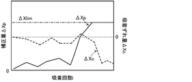
- the component mounting apparatus of the comparative example sets an upper limit (limit) on the correction amount, and when the correction amount corresponding to the positional deviation amount of the component P attracted this time reaches the limit, The target suction position of the part P is fixed at the position corrected by the correction amount corresponding to the limit.
- limit limit
- the correction amounts ⁇ Xp (i) and ⁇ Yp (i) corresponding to the positional deviations ⁇ Xc (i) and ⁇ Yc (i) of the component P attracted this time reach the limits. Then, the component to be sucked next by the correction amounts ⁇ Xp (in) and ⁇ Yp (in) corresponding to the positional deviations ⁇ Xc (in) and ⁇ Yc (in) of the component P sucked n times before.
- the target suction position (Xp, Yp) of P is updated.
- the component mounting apparatus 10 can suppress deterioration of the suction accuracy due to the amount of positional deviation recognized in the posture of the component different from that at the time of suction. Further, when the number of times the correction amounts ⁇ Xp and ⁇ Yp reach the limit (the number of times Nx and Ny reach the limit) reaches the threshold value Nref, the component mounting apparatus 10 of the present embodiment stops the subsequent suction processing. As a result, it is possible to prevent the suction process from being repeated and the frequent suction defects and mounting defects to occur in a state where the suction accuracy is unlikely to improve.
- the component supply device 21 of the present embodiment corresponds to the component supply device of the present disclosure
- the suction nozzle 25 corresponds to the suction nozzle
- the moving mechanism 23 and the elevating device correspond to the moving device
- the part camera 26 is the imaging device.
- the control device 30 corresponds to the control device.
- the control device 30 of the component mounting apparatus 10 determines that the correction amounts ⁇ Xp (i) and ⁇ Yp (i) corresponding to the positional deviations ⁇ Xc (i) and ⁇ Yc (i) of the component P attracted this time.
- the limit is reached, based on the correction amounts ⁇ Xp (in) and ⁇ Yp (in) according to the positional deviations ⁇ Xc (in) and ⁇ Yc (in) of the component P sucked n times before.
- the target suction position (Xp, Yp) of the next component P to be sucked is updated.
- the control device 30 may update the target suction position (Xp, Yp) by the following processing.
- FIG. 10 is a flowchart showing a target suction position updating process of the modified example.
- the same processes as the target suction position updating process of the embodiment shown in FIG. 5 are designated by the same reference numerals, and detailed description thereof will be omitted.
- the CPU 31 determines in step S220 that the amount of positional deviation ⁇ Xc (i) of the component P that has been suctioned this time is larger than the limit ⁇ Xlim, and increments the number of times Nx of reaching the limit in step S240. From the correction amount ⁇ Xp (i) corresponding to the positional deviation amount ⁇ Xc (i) of the component P picked up this time to the correction amount ⁇ Xp (i-1) corresponding to the positional deviation amount ⁇ Xc (i-1) of the component P previously picked up. It is determined whether the subtracted change amount is larger than the threshold value A (step S250B).
- step S250B is a process of determining whether or not the correction amount ⁇ Xp suddenly increases and reaches the limit ⁇ Xlim.
- the CPU 31 determines the correction amount ⁇ Xp (i-1) corresponding to the positional deviation amount ⁇ Xc (i-1) of the component P that has previously sucked the target suction position Xp.
- the value is updated to the offset value (step S260B).
- the CPU 31 determines that the amount of change is less than or equal to the threshold value A, the CPU 31 updates the target suction position Xp to a value offset by the correction amount corresponding to the limit ⁇ Xlim (step S270).
- step S210 the CPU 31 determines that the correction amount ⁇ Xp (i) corresponding to the position deviation amount ⁇ Xc (i) of the component P that has been picked up this time is smaller than the limit ( ⁇ Xlim), and increments the limit number of times Nx in step S280. Then, from the correction amount ⁇ Xp (i-1) corresponding to the positional deviation amount ⁇ Xc (i-1) of the previously picked-up component P to the correction amount ⁇ Xp (i) corresponding to the positional deviation amount ⁇ Xc (i) of the presently picked-up component P. It is determined whether or not the change amount obtained by subtracting) is larger than the threshold value A (step S290B).
- step S290B is a process of determining whether the correction amount ⁇ Xp suddenly decreases and reaches the limit ( ⁇ Xlim).
- the CPU 31 determines the correction amount ⁇ Xp (i-1) corresponding to the positional deviation amount ⁇ Xc (i-1) of the component P that has previously sucked the target suction position Xp.
- the value is updated to the offset value (step S300B).
- the CPU 31 determines that the amount of change is less than or equal to the threshold value A
- the CPU 31 updates the target suction position Xp to a value offset by the correction amount corresponding to the limit ( ⁇ Xlim) (step S310).
- step S340 When the CPU 31 determines in step S340 that the amount of positional deviation ⁇ Yc (i) of the component P that has been sucked this time is greater than the limit ⁇ Ylim, and increments the number of times Ny of reaching the limit in step S360, the amount of positional deviation ⁇ Yc of the component P that has been sucked this time is increased.
- the amount of change obtained by subtracting the correction amount ⁇ Yp (i-1) corresponding to the positional deviation amount ⁇ Yc (i-1) of the previously picked-up component P from the correction amount ⁇ Yp (i) corresponding to (i) is larger than the threshold value B. It is determined whether or not (step S370B).
- step S370B is a process of determining whether or not the correction amount ⁇ Yp suddenly increases and reaches the limit ⁇ Ylim.
- the CPU 31 determines the amount of correction ⁇ Yp (i-1) corresponding to the amount of positional deviation ⁇ Yp (i-1) of the component P that has previously sucked the target suction position Yp.
- the value is updated to the offset value (step S380B).
- the CPU 31 determines that the amount of change is less than or equal to the threshold value B, the CPU 31 updates the target suction position Yp to a value offset by the correction amount corresponding to the limit ⁇ Ylim (step S390).
- step S330 the CPU 31 determines that the correction amount ⁇ Yp (i) corresponding to the position deviation amount ⁇ Yc (i) of the component P that has been picked up this time is smaller than the limit ( ⁇ Ylim), and increments the limit number of times Ny in step S400. Then, from the correction amount ⁇ Yp (i-1) corresponding to the positional deviation amount ⁇ Yc (i-1) of the previously picked up component P to the correction amount ⁇ Xp (i) corresponding to the positional deviation amount ⁇ Yc (i) of the presently picked up component P. It is determined whether or not the change amount obtained by subtracting) is larger than the threshold value B (step S410B).
- step S410B is a process of determining whether the correction amount ⁇ Yp suddenly decreases and reaches the limit ( ⁇ Ylim).
- the CPU 31 determines the target suction position Yp by the correction amount ⁇ Yp (i-1) corresponding to the position shift amount ⁇ Yc (i-1) of the component P previously sucked.
- the value is updated to the offset value (step S420B).
- the CPU 31 determines that the change amount is equal to or less than the threshold value B
- the CPU 31 updates the target suction position Yp to a value offset by the correction amount corresponding to the limit ( ⁇ Ylim) (step S430).
- the CPU 31 offsets the target suction position by the correction amount corresponding to the displacement amount of the previously sucked component P. Update to value.
- the component mounting apparatus of the modified example as shown in FIG. 6, even if the position shift amount largely changes due to the difference in the posture of the component P between the pickup state and the image pickup state, The influence on the target suction position can be eliminated, and the deterioration of suction accuracy can be suppressed.
- the CPU 31 when the correction amount according to the positional deviation amount of the component P sucked this time reaches the limit, the CPU 31 corrects the target suction position according to the positional deviation amount of the component P suctioned a predetermined number of times before. Updated to a value offset by the amount. However, when the correction amount reaches the limit, the CPU 31 may update the target suction position with the correction amount smaller than the limit.
- the moving mechanism 23 moves the head 24 in the XY directions.
- the moving mechanism only needs to be movable relative to the component supply device 21, and may move the component supply device 21 in the XY directions.
- the component mounting apparatus of the present disclosure is the component mounting apparatus (10) that sucks the component (P) supplied by the component supply apparatus (12) and mounts it on the target object (S).
- a suction nozzle (25) for sucking the component (P)
- An image pickup device (26) for picking up the imaged component (P) and the moving device so that the component (P) supplied by the component supply device (12) is sucked by the suction nozzle (25) at a target suction position.
- the suction control that controls the suction nozzle (25), and the moving device (23) and the image pickup device (26) are controlled so that the component sucked by the suction nozzle (25) is imaged at a predetermined image pickup position.
- the target suction position is updated by the correction amount and the position shift is performed.
- the control device of the component mounting apparatus includes suction control that controls the component supplied by the component supply device to be sucked by the suction nozzle at the target suction position, and target suction position update processing that updates the target suction position. And execute.
- the target suction position update processing the component sucked by the suction nozzle is imaged at a predetermined image pickup position, and the correction amount according to the amount of displacement of the component recognized based on the imaged image of the component does not reach the limit. In this case, the target suction position is updated with the correction amount.
- the correction amount according to the positional deviation amount reaches the limit
- the target suction position is updated with the correction amount smaller than the limit.
- the component mounting apparatus of the present disclosure when the position of the component that is sucked by the suction nozzle is shifted due to some reason when the component is moved to the image capturing position, a position different from that at the time of suction is determined based on the captured image captured in that state.
- the shift amount may be recognized. Therefore, the component mounting apparatus of the present disclosure updates the target pick-up position with a correction amount smaller than the limit when the correction amount of the target pick-up position derived according to the amount of displacement of the part reaches the limit.
- the control device (30) executes the target suction position updating process a second predetermined number of times or more, which is larger than the first predetermined number, and is recognized in the target suction position updating process this time.
- the target is determined by the correction amount corresponding to the positional deviation amount recognized in the target suction position update process executed before the first predetermined number of times.
- the suction position may be updated. This makes it possible to reduce the influence on the target suction position even if the posture of the component differs between when picking up the image and when picking up the image, and even when a positional shift different from that at the time of picking up is recognized, suppressing deterioration of the suction accuracy. be able to.
- the “second predetermined number of times” may be the number of times required for the suction of the component by the suction nozzle to be stable.
- the control device (30) controls the correction amount according to the positional deviation amount recognized in the target suction position update processing of this time to reach the limit and the target suction position of this time. If the correction amount according to the position shift amount recognized in the update process has changed by a predetermined amount or more from the correction amount according to the position shift amount recognized in the previous target suction position update process, The target suction position may be updated by a correction amount according to the amount of positional deviation recognized in the target suction position updating process. By doing so, even if the amount of positional deviation greatly changes due to the difference in the posture of the component between when the component is picked up and when the image is picked up, it is possible to reduce the influence on the target pickup position. Can be suppressed.
- the control device (30) determines that the correction amount according to the position displacement amount has reached the limit, and the target suction position updating process has been performed a predetermined number of times. Then, the subsequent execution of the adsorption control may be stopped. By doing so, it is possible to prevent the suction process from being repeated and the frequent suction defects and mounting defects to occur in a state in which the suction accuracy is unlikely to improve.
- the present disclosure can be used in the manufacturing industry of component mounting devices and the like.
Landscapes
- Engineering & Computer Science (AREA)
- Manufacturing & Machinery (AREA)
- Microelectronics & Electronic Packaging (AREA)
- Operations Research (AREA)
- Supply And Installment Of Electrical Components (AREA)
Abstract
部品実装装置は、吸着ノズルと、吸着ノズルを部品供給装置に対して相対移動させる移動装置と、吸着ノズルに吸着された部品を撮像する撮像装置と、部品供給装置により供給された部品が目標吸着位置で前記吸着ノズルに吸着されるよう移動装置を制御する吸着制御と、吸着ノズルに吸着された部品が所定の撮像位置で撮像されるよう移動装置と撮像装置とを制御し部品の撮像画像に基づいて認識される部品の位置ずれ量に応じた補正量がリミットに達していない場合にはその補正量により目標吸着位置を更新し、位置ずれ量に応じた補正量がリミットに達している場合にはリミットよりも少ない補正量により目標吸着位置を更新する目標吸着位置更新処理と、を実行する制御装置と、を備える。
Description
本明細書は、部品実装装置について開示する。
従来、この種の部品実装装置としては、部品供給装置の電子部品(部品)の取出し位置に装着ヘッド(吸着ノズル)を移動させて装着ヘッドに部品を吸着させて取り出し、プリント基板(基板)上の装着位置に装着ヘッドを移動させて部品を基板に装着するものが提案されている(例えば、特許文献1参照)。部品実装装置は、装着ヘッドに部品を吸着させると、装着ヘッドを撮像位置へ移動させて装着ヘッドに吸着された部品を部品認識カメラで撮像し、得られた撮像画像に基づいて部品の位置ずれを認識する。そして、部品実装装置は、認識した位置ずれに基づいて装着位置を補正して部品を装着すると共に、認識した位置ずれに基づいて次の部品取出し動作に用いる取出し位置を算出する。また、部品実装装置は、算出した取出し位置がリミットの位置(移動許容範囲)をオーバーしているか否かを判定し、リミットの位置をオーバーしていると判定すると、以降の部品取出し動作を当該リミットの位置で行なうようにする。
部品の位置ずれは、上述したように、吸着ノズルを撮像位置へ移動させて撮像装置により吸着ノズルに吸着された部品を撮像することにより撮像画像に基づいて認識される。このとき、吸着ノズルに対する部品の吸着位置によっては、吸着ノズルに吸着された部品を撮像位置へ移動させる際に部品に作用する加速度や振動により当該部品の位置がずれてしまう場合があった。この場合、撮像画像に基づいて吸着時とは異なる部品の位置ずれが認識され、当該位置ずれに基づいて次の部品の取出し位置が算出される結果、部品の吸着精度が悪化してしまう。このため、特許文献1記載の部品実装装置のように、位置ずれに基づいて算出される取出し位置がリミットの位置をオーバーした場合に、以降の部品取出し動作の取出し位置を当該リミットの位置に固定すると、吸着精度が悪化した状態で部品を吸着し続けるおそれがある。
本開示は、部品の吸着精度の悪化を抑制することを主目的とする。
本開示は、上述の主目的を達成するために以下の手段を採った。
本開示の部品実装装置は、
部品供給装置により供給された部品を吸着して対象物に実装する部品実装装置であって、
前記部品を吸着する吸着ノズルと、
前記吸着ノズルを前記部品供給装置に対して相対移動させる移動装置と、
前記吸着ノズルに吸着された部品を撮像する撮像装置と、
前記部品供給装置により供給された部品が目標吸着位置で前記吸着ノズルに吸着されるよう前記移動装置を制御する吸着制御と、前記吸着ノズルに吸着された部品が所定の撮像位置で撮像されるよう前記移動装置と前記撮像装置とを制御し該部品の撮像画像に基づいて認識される該部品の位置ずれ量に応じた補正量がリミットに達していない場合には該補正量により前記目標吸着位置を更新し、前記位置ずれ量に応じた補正量が前記リミットに達している場合には該リミットよりも少ない補正量により前記目標吸着位置を更新する目標吸着位置更新処理と、を実行する制御装置と、
を備えることを要旨とする。
部品供給装置により供給された部品を吸着して対象物に実装する部品実装装置であって、
前記部品を吸着する吸着ノズルと、
前記吸着ノズルを前記部品供給装置に対して相対移動させる移動装置と、
前記吸着ノズルに吸着された部品を撮像する撮像装置と、
前記部品供給装置により供給された部品が目標吸着位置で前記吸着ノズルに吸着されるよう前記移動装置を制御する吸着制御と、前記吸着ノズルに吸着された部品が所定の撮像位置で撮像されるよう前記移動装置と前記撮像装置とを制御し該部品の撮像画像に基づいて認識される該部品の位置ずれ量に応じた補正量がリミットに達していない場合には該補正量により前記目標吸着位置を更新し、前記位置ずれ量に応じた補正量が前記リミットに達している場合には該リミットよりも少ない補正量により前記目標吸着位置を更新する目標吸着位置更新処理と、を実行する制御装置と、
を備えることを要旨とする。
この本開示の部品実装装置の制御装置は、部品供給装置により供給された部品が目標吸着位置で吸着ノズルに吸着されるよう制御する吸着制御と、その目標吸着位置を更新する目標吸着位置更新処理とを実行する。目標吸着位置更新処理は、吸着ノズルに吸着された部品を所定の撮像位置で撮像し、その部品の撮像画像に基づいて認識される部品の位置ずれ量に応じた補正量がリミットに達していない場合には、その補正量により目標吸着位置を更新する。一方、位置ずれ量に応じた補正量がリミットに達した場合には、リミットよりも少ない補正量により目標吸着位置を更新する。本開示の部品実装装置は、吸着ノズルに吸着された部品を撮像位置へ移動させる際に何らかの原因により部品の位置がずれると、その状態で撮像された撮像画像に基づいて吸着時とは異なる位置ずれ量が認識される場合がある。そこで、本開示の部品実装装置は、部品の位置ずれ量に応じて導出される目標吸着位置の補正量がリミットに達した場合に、リミットよりも少ない補正量により目標吸着位置を更新して次の吸着制御を実行することで、吸着時とは異なる姿勢で認識された部品の位置ずれ量による目標吸着位置への影響を小さくすることができる。この結果、吸着時とは異なる部品の姿勢で部品の位置ずれ量が認識された場合でも、それによる吸着精度の悪化を抑制することが可能となる。
次に、本開示を実施するための形態について図面を参照しながら説明する。
図1は、本実施形態の部品実装装置10の構成の概略を示す構成図である。図2は、制御装置30の電気的な接続関係を示す説明図である。なお、図1の左右方向がX軸方向であり、前(手前)後(奥)方向がY軸方向であり、上下方向がZ軸方向である。
部品実装装置10は、図1に示すように、部品供給装置21と、基板搬送装置22と、移動機構23と、ヘッド24と、吸着ノズル25と、パーツカメラ26と、マークカメラ27と、ノズルストッカ28と、制御装置30(図2参照)と、を備える。
部品供給装置21は、部品Pを部品供給位置まで供給するものである。部品供給装置21は、所定間隔毎に形成された収容部に部品Pが収容されたテープをリールから引き出してピッチ送りすることで、部品Pを部品供給位置に供給するテープフィーダとして構成される。テープフィーダは、筐体12を支持する基台11の前部に設けられた左右方向(X軸方向)に並ぶ複数のフィーダ台に対してそれぞれ着脱可能に取り付けられる。
基板搬送装置22は、基台11の中央部から後部にかけて設けられ、図中、左右方向(X軸方向)に沿って基板Sの搬入,固定,搬出を行なうものである。基板搬送装置22は、前後に間隔を空けて設けられ左右方向に架け渡された一対のコンベアベルトを有する。基板Sは、コンベアベルトによって搬送される。
ヘッド24は、部品供給位置に供給された部品Pを吸着して基板S上に実装するものである。ヘッド24は、吸着ノズル25が着脱可能なノズルホルダと、ノズルホルダを吸着ノズル25と共に昇降(Z軸方向に移動)させる昇降装置と、備える。吸着ノズル25は、吸着口に給排される負圧によって部品Pを吸着する。
移動機構23は、ヘッド24をXY方向に移動させるものである。移動機構23は、例えば、ボールねじ機構により構成することができる。
パーツカメラ26は、基台11の部品供給装置21と基板搬送装置22との間に設けられ、吸着ノズル25に吸着された部品Pを下方から撮像するものである。マークカメラ27は、ヘッド24に設けられ、基板Sに付された位置決め基準マークを上方から撮像するものである。ノズルストッカ28は、パーツカメラ26に隣接して設けられ、交換用の吸着ノズル25を複数ストックするものである。
制御装置30は、図2に示すように、CPU31とROM32とHDD33とRAM34と入出力インタフェース35とを備える。これらはバス36を介して電気的に接続されている。制御装置30には、パーツカメラ26やマークカメラ27からの画像信号、吸着ノズル25のX方向,Y方向およびZ方向における各位置を検出する位置センサからの検知信号などが入出力インタフェース35を介して入力されている。一方、制御装置30からは、部品供給装置21や基板搬送装置22、移動機構23、ヘッド24などへの制御信号が入出力インタフェース35を介して出力されている。また、制御装置30は、管理装置40と双方向通信可能に接続されており、互いにデータや制御信号のやり取りを行っている。
管理装置40は、例えば、汎用のコンピュータであり、図2に示すように、CPU41とROM42とHDD43とRAM44と入出力インタフェース45などを備える。これらは、バス46を介して電気的に接続されている。この管理装置40には、マウスやキーボード等の入力デバイス47から入力信号が入出力インタフェース45を介して入力されている。また、管理装置40からは、ディスプレイ48への画像信号が入出力インタフェース45を介して出力されている。HDD43は、基板Sの生産プログラムを記憶している。ここで、基板Sの生産プログラムとは、各部品実装装置10においてどの部品Pをどの順番で基板Sへ実装するか、また、そのように部品Pを実装した基板Sを何枚作製するかなどを定めた処理が記述されたものである。
次に、こうして構成された本実施形態の部品実装装置10の動作について説明する。図3は、制御装置30により実行される部品実装処理の一例を示すフローチャートである。この処理は、フィーダごとに実行される。すなわち、同一のフィーダから供給された部品に対しては、同一の部品実装処理が実行され、別のフィーダから供給される部品に対しては、別の部品実装処理が実行される。
部品実装処理が実行されると、制御装置30のCPU31は、まず、吸着ノズル25を目標吸着位置(Xp,Yp)の上方に移動させると共に下降させて当該吸着ノズル25に部品Pが吸着されるよう移動機構23とヘッド24とを制御する(ステップS100)。ここで、目標吸着位置(Xp,Yp)は、フィーダごとに定められている。次に、CPU31は、吸着ノズル25に吸着させた部品Pがパーツカメラ26の上方へ移動するよう移動機構23を制御すると共に当該部品Pが撮像されるようパーツカメラ26を制御する(ステップS110)。続いて、CPU31は、得られた撮像画像を処理して実際の吸着位置を認識し、認識した実際の吸着位置と理想位置との間のX軸方向およびY軸方向における位置ずれ量ΔXc(i),ΔYc(i)を取得する(ステップS120)。なお、iは、同一のフィーダから吸着した部品Pの吸着回数を示す。したがって、ΔXc(i),ΔYc(i)は、同一フィーダからi回目に吸着した部品Pの位置ずれ量を意味する。次に、CPU31は、吸着ノズル25に吸着させた部品Pの目標実装位置(X*,Y*)を位置ずれ量ΔXc(i),ΔYc(i)の分だけ同方向にオフセットすることにより目標実装位置(X*,Y*)を補正する(ステップS130)。そして、CPU31は、吸着ノズル25に吸着させた部品Pを補正後の目標実装位置(X*,Y*)の上方に移動させると共に下降させて当該部品Pが基板Sに実装されるよう移動機構23とヘッド24とを制御する(ステップS140)。図4に示すように、部品供給装置21により供給された部品Pは、部品供給位置(Xp,Yp)にて吸着され、パーツカメラ26の上方で撮像された後、基板S上の目標実装位置(X*,Y*)まで搬送させられて実装させられる。
次に、CPU31は、ステップS100で用いる目標吸着位置(Xp,Yp)を更新する目標吸着位置更新処理を実行する(ステップS150)。以下、目標吸着位置更新処理の詳細について説明する。図5は、目標吸着位置更新処理の一例を示すフローチャートである。この目標吸着位置更新処理では、CPU31は、まず、ステップS120で取得したX軸方向の位置ずれ量ΔXc(i)に係数kを乗じてマイナスの符号を付したものをX軸方向の目標吸着位置Xpの補正量ΔXp(i)として設定する(ステップS200)。ここで、係数kは、値1に定められてもよいし、値0よりも大きく且つ値1よりも小さい値に定められてもよい。続いて、CPU31は、X軸方向の補正量Xpが予め定められたリミット(-ΔXlim)以上であるか否か(ステップS210)、X軸方向の補正量ΔXp(i)がリミットΔXlim以下であるか否かを判定する(ステップS220)。ここで、リミットΔXlim,-ΔXlimは、X軸方向(右方向と左方向)の補正量の許容限界値である。CPU31は、補正量ΔXp(i)がリミットΔ(-Xlim)以上であり且つリミットΔXlim以下であると判定すると、同一のフィーダから次に吸着する部品PのX軸方向の目標吸着位置Xpを、今回吸着した部品Pの位置ずれ量ΔXc(i)に応じた補正量ΔXpの分だけオフセットした値に更新する(ステップS230)。これにより、部品実装装置10は、次に吸着する部品PのX軸方向の吸着位置を理想位置に近づけることができる。
CPU31は、ステップS220においてX軸方向の補正量ΔXp(i)がリミットΔXlimよりも大きいと判定すると、リミット到達回数Nxを値1だけインクリメントし(ステップS240)、同一フィーダからの部品Pの吸着回数iがm回よりも多いか否かを判定する(ステップS250)。ここで、m回は、吸着ノズル25による部品Pの吸着が安定するのに要する回数であり、後述するn回(例えば3回)よりも多い回数に定められている。CPU31は、吸着回数iがm回よりも多いと判定すると、同一のフィーダから次に吸着する部品PのX軸方向の目標吸着位置Xpを、n(<m)回前に吸着した部品Pの位置ずれ量ΔXc(i-n)に応じた補正量ΔXp(i-n)の分だけオフセットした値に更新する(ステップS260)。一方、CPU31は、吸着回数iがm回よりも多くない、即ちm回以下であると判定すると、目標吸着位置XpをリミットΔXlimに相当する補正量の分だけオフセットした値に更新する(ステップS270)。
CPU31は、ステップS210においてX軸方向の補正量ΔXp(i)がリミット(-ΔXlim)よりも小さいと判定すると、リミット到達回数Nxを値1だけインクリメントし(ステップS280)、吸着回数iがm回よりも多いか否かを判定する(ステップS290)。CPU31は、吸着回数iがm回よりも多いと判定すると、同一のフィーダから次に吸着する部品PのX軸方向の目標吸着位置Xpを、n回前に吸着した部品Pの位置ずれ量ΔXc(i-n)に応じた補正量ΔXp(i-n)の分だけオフセットした値に更新する(ステップS300)。一方、CPU31は、吸着回数iがm回よりも多くない、即ちm回以下であると判定すると、目標吸着位置Xpをリミット(-ΔXlim)に相当する補正量の分だけオフセットした値に更新する(ステップS310)。
次に、CPU31は、ステップS120で取得したY軸方向の位置ずれ量ΔYc(i)に係数kを乗じてマイナスの符号を付したものをY軸方向の目標吸着位置Ypの補正量ΔYp(i)として設定する(ステップS320)。続いて、CPU31は、Y軸方向の補正量ΔYpが予め定められたリミット(-ΔYlim)以上であるか否か(ステップS330)、Y軸方向の補正量ΔYp(i)がリミットΔYlim以下であるか否かを判定する(ステップS340)。ここで、リミットΔYlim,-ΔYlimは、Y軸方向(前方向と後方向)の補正量の許容限界値である。CPU31は、補正量ΔYp(i)がリミット(-ΔYlim)以上であり且つリミットΔYlim以下であると判定すると、同一のフィーダから次に吸着する部品PのY軸方向の目標吸着位置Ypを、今回吸着した部品Pの位置ずれ量ΔYc(i)に応じた補正量ΔYp(i)の分だけオフセットした値に更新して(ステップS350)、目標吸着位置更新処理を終了する。これにより、部品実装装置10は、次に吸着する部品PのY軸方向の吸着位置を理想位置に近づけることができる。
CPU31は、ステップS340においてY軸方向の補正量ΔYp(i)がリミットΔYlimよりも大きいと判定すると、リミット到達回数Nyを値1だけインクリメントし(ステップS360)、同一フィーダからの部品Pの吸着回数iがm回よりも多いか否かを判定する(ステップS370)。CPU31は、吸着回数iがm回よりも多いと判定すると、同一のフィーダから次に吸着する部品PのY軸方向の目標吸着位置Ypを、n回前に吸着した部品Pの位置ずれ量ΔYc(i-n)に応じた補正量ΔYp(i-n)の分だけオフセットした値に更新して(ステップS380)、目標吸着位置更新処理を終了する。一方、CPU31は、吸着回数iがm回よりも多くない、即ちm回以下であると判定すると、目標吸着位置YpをリミットΔYlimに相当する補正量の分だけオフセットした値に更新して(ステップS390)、目標吸着位置更新処理を終了する。
CPU31は、ステップS330においてY軸方向の補正量ΔYp(i)がリミット(-ΔYlim)よりも小さいと判定すると、リミット到達回数Nyを値1だけインクリメントし(ステップS400)、吸着回数iがm回よりも多いか否かを判定する(ステップS410)。CPU31は、吸着回数iがm回よりも多いと判定すると、同一のフィーダから次に吸着する部品PのY軸方向の目標吸着位置Ypを、n回前に吸着した部品Pの位置ずれ量ΔYc(i-n)に応じた補正量ΔYp(i-n)の分だけオフセットした値に更新して(ステップS420)、目標吸着位置更新処理を終了する。一方、CPU31は、吸着回数iがm回よりも多くない、即ちm回以下であると判定すると、目標吸着位置Ypをリミット(-ΔYlim)に相当する補正量の分だけオフセットした値に更新して(ステップS430)、目標吸着位置更新処理を終了する。
部品実装処理に戻って、CPU31は、こうしてステップS150の目標吸着位置更新処理を実行すると、リミット到達回数Nxおよびリミット到達回数Nyのいずれかが閾値Nref(例えば3回や4回)に達したか否かを判定する(ステップS160)。CPU31は、リミット到達回数Nxおよびリミット到達回数Nyのいずれもが閾値Nrefに達していないと判定すると、iを値1だけインクリメントし(ステップS170)、ステップS100に戻って吸着処理を繰り返す。一方、CPU31は、リミット到達回数Nxおよびリミット到達回数Nyのいずれかが閾値Nrefに達したと判定すると、対象のフィーダからの部品の吸着処理を中止して(ステップS180)、部品実装処理を終了する。
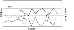
部品Pの位置ずれは、上述したように、吸着ノズル25に吸着された部品Pをパーツカメラ26の上方へ移動させて当該部品Pを撮像することにより撮像画像に基づいて認識される。このとき、吸着ノズル25に吸着された部品Pは、フィーダの部品供給位置からパーツカメラ26上方の撮像位置へ移動させられる際の加速度や振動によりその吸着位置がずれてしまう場合があった。この場合、撮像画像に基づいて吸着時とは異なる部品Pの位置ずれが認識され、当該位置ずれに基づいて次に吸着する部品Pの目標吸着位置(Xp,Yp)が算出される結果、部品Pの吸着精度が悪化してしまう。例えば、図6に示すように、部品Pは、何らかの原因により吸着ノズル25が上面右端で吸着されると、搬送時の加速度や振動によって吸着ノズル25の先端を中心として吸着ノズル25の軸回りに回転し、上面左端で吸着された姿勢となる場合がある(図6(a)~(c)参照)。この場合、吸着時の姿勢とは異なる部品Pの姿勢により位置ずれが認識される。そして、認識された位置ずれに基づいて次に吸着する部品Pの目標吸着位置(Xp,Yp)が更新される結果、次の部品Pは、今回の部品Pよりも大きく左方向にずれた位置で吸着されてしまう(図6(d)参照)。この結果、吸着不良や実装不良を招く。ここで、比較例の部品実装装置は、図7に示すように、補正量に上限(リミット)を設け、今回吸着した部品Pの位置ずれ量に応じた補正量がリミットに到達すると、以降の部品Pの目標吸着位置をリミットに相当する補正量で補正した位置に固定する。しかし、比較例の部品実装機では、図7に示すように、吸着精度(位置ずれ量ΔXc)が不安定な状態がキープされるだけで、吸着精度が良好な状態に戻るチャンスがない。これに対して、本実施形態の部品実装装置10は、今回吸着した部品Pの位置ずれΔXc(i),ΔYc(i)に応じた補正量ΔXp(i),ΔYp(i)がリミットに到達すると、n回前に吸着した部品Pの位置ずれΔXc(i-n),ΔYc(i-n)に応じた補正量ΔXp(i-n),ΔYp(i-n)により次に吸着する部品Pの目標吸着位置(Xp,Yp)を更新する。これにより、本実施形態の部品実装装置10では、図8に示すように、位置ずれ量が大きく変動し、補正量が繰り返しリミットに到達する場合も考えられるが、図9に示すように、吸着精度が良好な状態に戻ることもある。この結果、本実施形態の部品実装装置10は、吸着時とは異なる部品の姿勢で認識された位置ずれ量による吸着精度の悪化を抑制することが可能となる。また、本実施形態の部品実装装置10は、補正量ΔXp,ΔYpがリミットに到達した回数(リミット到達回数Nx,Ny)が閾値Nrefに達すると、以降の吸着処理を中止する。これにより、吸着精度が改善する見込みがない状態で、吸着処理が繰り返され、吸着不良や実装不良が頻発するのを抑制することができる。
ここで、実施形態の主要な要素と請求の範囲に記載した本開示の主要な要素との対応関係について説明する。即ち、本実施形態の部品供給装置21が本開示の部品供給装置に相当し、吸着ノズル25が吸着ノズルに相当し、移動機構23や昇降装置が移動装置に相当し、パーツカメラ26が撮像装置に相当し、制御装置30が制御装置に相当する。
なお、本開示は上述した実施形態に何ら限定されることはなく、本開示の技術的範囲に属する限り種々の態様で実施し得ることはいうまでもない。
例えば、上述した実施形態では、部品実装装置10の制御装置30は、今回吸着した部品Pの位置ずれΔXc(i),ΔYc(i)に応じた補正量ΔXp(i),ΔYp(i)がリミットに到達すると、n回前に吸着した部品Pの位置ずれΔXc(i-n),ΔYc(i-n)に応じた補正量ΔXp(i-n),ΔYp(i-n)に基づいて次に吸着する部品Pの目標吸着位置(Xp,Yp)を更新した。しかし、制御装置30は、以下の処理により目標吸着位置(Xp,Yp)を更新してもよい。図10は、変形例の目標吸着位置更新処理を示すフローチャートである。変形例の目標吸着位置更新処理の各処理のうち、図5に示す実施形態の目標吸着位置更新処理と同一の処理については、同一の符号を付し、その詳細な説明を省略する。
変形例の目標吸着位置更新処理では、CPU31は、ステップS220で今回吸着した部品Pの位置ずれ量ΔXc(i)がリミットΔXlimよりも大きいと判定し、ステップS240でリミット到達回数Nxをインクリメントすると、今回吸着した部品Pの位置ずれ量ΔXc(i)に応じた補正量ΔXp(i)から前回吸着した部品Pの位置ずれ量ΔXc(i-1)に応じた補正量ΔXp(i-1)を減じた変化量が閾値Aよりも大きいか否かを判定する(ステップS250B)。ステップS250Bの処理は、補正量ΔXpが急増してリミットΔXlimに到達したかを判定する処理である。CPU31は、上記変化量が閾値Aよりも大きいと判定すると、目標吸着位置Xpを前回吸着した部品Pの位置ずれ量ΔXc(i-1)に応じた補正量ΔXp(i-1)の分だけオフセットした値に更新する(ステップS260B)。一方、CPU31は、上記変化量が閾値A以下であると判定すると、目標吸着位置XpをリミットΔXlimに相当する補正量の分だけオフセットした値に更新する(ステップS270)。
CPU31は、ステップS210で今回吸着した部品Pの位置ずれ量ΔXc(i)に応じた補正量ΔXp(i)がリミット(-ΔXlim)よりも小さいと判定し、ステップS280でリミット到達回数Nxをインクリメントすると、前回吸着した部品Pの位置ずれ量ΔXc(i-1)に応じた補正量ΔXp(i-1)から今回吸着した部品Pの位置ずれ量ΔXc(i)に応じた補正量ΔXp(i)を減じた変化量が閾値Aよりも大きいか否かを判定する(ステップS290B)。ステップS290Bの処理は、補正量ΔXpが急減してリミット(-ΔXlim)に到達したかを判定する処理である。CPU31は、上記変化量が閾値Aよりも大きいと判定すると、目標吸着位置Xpを前回吸着した部品Pの位置ずれ量ΔXc(i-1)に応じた補正量ΔXp(i-1)の分だけオフセットした値に更新する(ステップS300B)。一方、CPU31は、上記変化量が閾値A以下であると判定すると、目標吸着位置Xpをリミット(-ΔXlim)に相当する補正量の分だけオフセットした値に更新する(ステップS310)。
CPU31は、ステップS340で今回吸着した部品Pの位置ずれ量ΔYc(i)がリミットΔYlimよりも大きいと判定し、ステップS360でリミット到達回数Nyをインクリメントすると、今回吸着した部品Pの位置ずれ量ΔYc(i)に応じた補正量ΔYp(i)から前回吸着した部品Pの位置ずれ量ΔYc(i-1)に応じた補正量ΔYp(i-1)を減じた変化量が閾値Bよりも大きいか否かを判定する(ステップS370B)。ステップS370Bの処理は、補正量ΔYpが急増してリミットΔYlimに到達したかを判定する処理である。CPU31は、上記変化量が閾値Bよりも大きいと判定すると、目標吸着位置Ypを前回吸着した部品Pの位置ずれ量ΔYp(i-1)に応じた補正量ΔYp(i-1)の分だけオフセットした値に更新する(ステップS380B)。一方、CPU31は、上記変化量が閾値B以下であると判定すると、目標吸着位置YpをリミットΔYlimに相当する補正量の分だけオフセットした値に更新する(ステップS390)。
CPU31は、ステップS330で今回吸着した部品Pの位置ずれ量ΔYc(i)に応じた補正量ΔYp(i)がリミット(-ΔYlim)よりも小さいと判定し、ステップS400でリミット到達回数Nyをインクリメントすると、前回吸着した部品Pの位置ずれ量ΔYc(i-1)に応じた補正量ΔYp(i-1)から今回吸着した部品Pの位置ずれ量ΔYc(i)に応じた補正量ΔXp(i)を減じた変化量が閾値Bよりも大きいか否かを判定する(ステップS410B)。ステップS410Bの処理は、補正量ΔYpが急減してリミット(-ΔYlim)に到達したかを判定する処理である。CPU31は、上記変化量が閾値Bよりも大きいと判定すると、目標吸着位置Ypを前回吸着した部品Pの位置ずれ量ΔYc(i-1)に応じた補正量ΔYp(i-1)の分だけオフセットした値に更新する(ステップS420B)。一方、CPU31は、上記変化量が閾値B以下であると判定すると、目標吸着位置Ypをリミット(-ΔYlim)に相当する補正量の分だけオフセットした値に更新する(ステップS430)。
こうした変形例の目標吸着位置更新処理では、CPU31は、補正量が急変してリミットに到達した場合は、目標吸着位置を前回吸着した部品Pの位置ずれ量に応じた補正量の分だけオフセットした値に更新する。これにより、変形例の部品実装装置は、図6に示すように、部品Pの姿勢が吸着時と撮像時とで異なることに起因して、位置ずれ量が大きく変化した状態が生じても、目標吸着位置に与える影響をなくすことができ、吸着精度の悪化を抑制することができる。
上述した実施形態では、CPU31は、今回吸着した部品Pの位置ずれ量に応じた補正量がリミットに到達した場合、目標吸着位置を所定回前に吸着した部品Pの位置ずれ量に応じた補正量の分だけオフセットした値に更新した。しかし、CPU31は、補正量がリミットに到達した場合、目標吸着位置をリミットよりも少ない補正量により更新するものであればよい。
上述した実施形態では、移動機構23は、ヘッド24をXY方向に移動させるものとした。しかし、移動機構は、部品供給装置21に対して相対移動可能なものであればよく、部品供給装置21をXY方向に移動させるものとしてもよい。
以上説明したように、本開示の部品実装装置は、部品供給装置(12)により供給された部品(P)を吸着して対象物(S)に実装する部品実装装置(10)であって、前記部品(P)を吸着する吸着ノズル(25)と、前記吸着ノズル(25)を前記部品供給装置(12)に対して相対移動させる移動装置(23)と、前記吸着ノズル(25)に吸着された部品(P)を撮像する撮像装置(26)と、前記部品供給装置(12)により供給された部品(P)が目標吸着位置で前記吸着ノズル(25)に吸着されるよう前記移動装置(23)を制御する吸着制御と、前記吸着ノズル(25)に吸着された部品が所定の撮像位置で撮像されるよう前記移動装置(23)と前記撮像装置(26)とを制御し該部品(P)の撮像画像に基づいて認識される該部品(P)の位置ずれ量に応じた補正量がリミットに達していない場合には該補正量により前記目標吸着位置を更新し、前記位置ずれ量に応じた補正量が前記リミットに達している場合には該リミットよりも少ない補正量により前記目標吸着位置を更新する目標吸着位置更新処理と、を実行する制御装置(30)と、を備えることを要旨とする。
この本開示の部品実装装置の制御装置は、部品供給装置により供給された部品が目標吸着位置で吸着ノズルに吸着されるよう制御する吸着制御と、その目標吸着位置を更新する目標吸着位置更新処理とを実行する。目標吸着位置更新処理は、吸着ノズルに吸着された部品を所定の撮像位置で撮像し、その部品の撮像画像に基づいて認識される部品の位置ずれ量に応じた補正量がリミットに達していない場合には、その補正量により目標吸着位置を更新する。一方、位置ずれ量に応じた補正量がリミットに達した場合には、リミットよりも少ない補正量により目標吸着位置を更新する。本開示の部品実装装置は、吸着ノズルに吸着された部品を撮像位置へ移動させる際に何らかの原因により部品の位置がずれると、その状態で撮像された撮像画像に基づいて吸着時とは異なる位置ずれ量が認識される場合がある。そこで、本開示の部品実装装置は、部品の位置ずれ量に応じて導出される目標吸着位置の補正量がリミットに達した場合に、リミットよりも少ない補正量により目標吸着位置を更新して次の吸着制御を実行することで、吸着時とは異なる姿勢で認識された部品の位置ずれ量による目標吸着位置への影響を小さくすることができる。この結果、吸着時とは異なる部品の姿勢で部品の位置ずれ量が認識された場合でも、それによる吸着精度の悪化を抑制することが可能となる。
こうした本開示の部品実装装置において、前記制御装置(30)は、前記目標吸着位置更新処理を第1所定回数よりも多い第2所定回数以上実行すると共に今回の前記目標吸着位置更新処理において認識される位置ずれ量に応じた補正量が前記リミットに達している場合には、前記第1所定回数前に実行した前記目標吸着位置更新処理において認識された位置ずれ量に応じた補正量により前記目標吸着位置を更新するものとしてもよい。こうすれば、部品の姿勢が吸着時と撮像時とで異なり、吸着時とは異なる位置ずれが認識されても、目標吸着位置に与える影響を小さくすることができ、吸着精度の悪化を抑制することができる。ここで、「第2所定回数」は、吸着ノズルによる部品の吸着が安定するのに要する回数であるものとすることができる。
また、本開示の部品実装装置において、前記制御装置(30)は、今回の前記目標吸着位置更新処理において認識される位置ずれ量に応じた補正量が前記リミットに達し且つ今回の前記目標吸着位置更新処理において認識される位置ずれ量に応じた補正量が前回の前記目標吸着位置更新処理において認識された位置ずれ量に応じた補正量に対して所定量以上変化している場合には、前回の前記目標吸着位置更新処理において認識された位置ずれ量に応じた補正量により前記目標吸着位置を更新するものとしてもよい。こうすれば、部品の姿勢が吸着時と撮像時とで異なることに起因して、位置ずれ量が大きく変化した状態が生じても、目標吸着位置に与える影響を小さくすることができ、吸着精度の悪化を抑制することができる。
さらに、本開示の部品実装装置において、前記制御装置(30)は、前記位置ずれ量に応じた補正量が前記リミットに達したと判定した前記目標吸着位置更新処理の実行回数が所定回数に達すると、以降の前記吸着制御の実行を中止するものとしてもよい。こうすれば、吸着精度が改善する見込みがない状態で、吸着処理が繰り返され、吸着不良や実装不良が頻発するのを抑制することができる。
本開示は、部品実装装置の製造産業などに利用可能である。
10 部品実装装置、11 基台、12 筐体、21 部品供給装置、22 基板搬送装置、23 移動機構、24 ヘッド、25 吸着ノズル、26 パーツカメラ、27 マークカメラ、28 ノズルストッカ、30 制御装置、31 CPU、32 ROM、33 HDD、34 RAM、35 入出力インタフェース、36 バス、40 管理装置、41 CPU、42 ROM、43 HDD、44 RAM、45 入出力インタフェース、46 バス、47 入力デバイス、48 ディスプレイ、P 部品、S 基板。
Claims (5)
- 部品供給装置により供給された部品を吸着して対象物に実装する部品実装装置であって、
前記部品を吸着する吸着ノズルと、
前記吸着ノズルを前記部品供給装置に対して相対移動させる移動装置と、
前記吸着ノズルに吸着された部品を撮像する撮像装置と、
前記部品供給装置により供給された部品が目標吸着位置で前記吸着ノズルに吸着されるよう前記移動装置を制御する吸着制御と、前記吸着ノズルに吸着された部品が所定の撮像位置で撮像されるよう前記移動装置と前記撮像装置とを制御し該部品の撮像画像に基づいて認識される該部品の位置ずれ量に応じた補正量がリミットに達していない場合には該補正量により前記目標吸着位置を更新し、前記位置ずれ量に応じた補正量が前記リミットに達している場合には該リミットよりも少ない補正量により前記目標吸着位置を更新する目標吸着位置更新処理と、を実行する制御装置と、
を備える部品実装装置。 - 請求項1に記載の部品実装装置であって、
前記制御装置は、前記目標吸着位置更新処理を第1所定回数よりも多い第2所定回数以上実行すると共に今回の前記目標吸着位置更新処理において認識される位置ずれ量に応じた補正量が前記リミットに達している場合には、前記第1所定回数前に実行した前記目標吸着位置更新処理において認識された位置ずれ量に応じた補正量により前記目標吸着位置を更新する、
部品実装装置。 - 請求項1または2に記載の部品実装装置であって、
前記制御装置は、今回の前記目標吸着位置更新処理において認識される位置ずれ量に応じた補正量が前記リミットに達し且つ今回の前記目標吸着位置更新処理において認識される位置ずれ量に応じた補正量が前回の前記目標吸着位置更新処理において認識された位置ずれ量に応じた補正量に対して所定量以上変化している場合には、前回の前記目標吸着位置更新処理において認識された位置ずれ量に応じた補正量により前記目標吸着位置を更新する、
部品実装装置。 - 請求項1ないし3いずれか1項に記載の部品実装装置であって、
前記制御装置は、前記位置ずれ量に応じた補正量が前記リミットに達したと判定した前記目標吸着位置更新処理の実行回数が所定回数に達すると、以降の前記吸着制御の実行を中止する、
部品実装装置。 - 請求項1ないし4いずれか1項に記載の部品実装装置であって、
前記制御装置は、前記吸着制御と前記目標吸着位置更新処理とを繰り返し実行する、
部品実装装置。
Priority Applications (2)
| Application Number | Priority Date | Filing Date | Title |
|---|---|---|---|
| PCT/JP2018/042962 WO2020105134A1 (ja) | 2018-11-21 | 2018-11-21 | 部品実装装置 |
| JP2020557077A JP7169366B2 (ja) | 2018-11-21 | 2018-11-21 | 部品実装装置 |
Applications Claiming Priority (1)
| Application Number | Priority Date | Filing Date | Title |
|---|---|---|---|
| PCT/JP2018/042962 WO2020105134A1 (ja) | 2018-11-21 | 2018-11-21 | 部品実装装置 |
Publications (1)
| Publication Number | Publication Date |
|---|---|
| WO2020105134A1 true WO2020105134A1 (ja) | 2020-05-28 |
Family
ID=70773362
Family Applications (1)
| Application Number | Title | Priority Date | Filing Date |
|---|---|---|---|
| PCT/JP2018/042962 Ceased WO2020105134A1 (ja) | 2018-11-21 | 2018-11-21 | 部品実装装置 |
Country Status (2)
| Country | Link |
|---|---|
| JP (1) | JP7169366B2 (ja) |
| WO (1) | WO2020105134A1 (ja) |
Families Citing this family (1)
| Publication number | Priority date | Publication date | Assignee | Title |
|---|---|---|---|---|
| CN118145124B (zh) * | 2023-12-21 | 2026-04-28 | 精恒新(厦门)科技股份有限公司 | 视觉盖帽机 |
Citations (4)
| Publication number | Priority date | Publication date | Assignee | Title |
|---|---|---|---|---|
| JP2012502321A (ja) * | 2008-09-08 | 2012-01-26 | クゥアルコム・インコーポレイテッド | 構成可能なインターフェースをもつマルチパネルデバイス |
| JP2012190297A (ja) * | 2011-03-11 | 2012-10-04 | Kyocera Corp | 電子機器 |
| WO2013046987A1 (ja) * | 2011-09-26 | 2013-04-04 | 日本電気株式会社 | 情報処理端末および情報処理方法 |
| JP2014107714A (ja) * | 2012-11-28 | 2014-06-09 | Nec Casio Mobile Communications Ltd | 携帯端末装置 |
Family Cites Families (6)
| Publication number | Priority date | Publication date | Assignee | Title |
|---|---|---|---|---|
| JPH05145289A (ja) * | 1991-11-20 | 1993-06-11 | Tokico Ltd | 部品取付装置 |
| JPH06244598A (ja) * | 1993-02-22 | 1994-09-02 | Matsushita Electric Ind Co Ltd | 電子部品実装装置及び部品実装方法 |
| JP3545108B2 (ja) * | 1995-09-13 | 2004-07-21 | 株式会社日立ハイテクインスツルメンツ | 電子部品自動装着装置及び装着方法 |
| JP2002118396A (ja) | 2000-10-06 | 2002-04-19 | Matsushita Electric Ind Co Ltd | 電子部品実装装置および電子部品実装方法 |
| JP4176439B2 (ja) | 2002-10-03 | 2008-11-05 | Juki株式会社 | 部品実装装置 |
| JP4622912B2 (ja) | 2006-03-30 | 2011-02-02 | パナソニック株式会社 | 認識対象の中心位置を認識する方法および装置 |
-
2018
- 2018-11-21 JP JP2020557077A patent/JP7169366B2/ja active Active
- 2018-11-21 WO PCT/JP2018/042962 patent/WO2020105134A1/ja not_active Ceased
Patent Citations (4)
| Publication number | Priority date | Publication date | Assignee | Title |
|---|---|---|---|---|
| JP2012502321A (ja) * | 2008-09-08 | 2012-01-26 | クゥアルコム・インコーポレイテッド | 構成可能なインターフェースをもつマルチパネルデバイス |
| JP2012190297A (ja) * | 2011-03-11 | 2012-10-04 | Kyocera Corp | 電子機器 |
| WO2013046987A1 (ja) * | 2011-09-26 | 2013-04-04 | 日本電気株式会社 | 情報処理端末および情報処理方法 |
| JP2014107714A (ja) * | 2012-11-28 | 2014-06-09 | Nec Casio Mobile Communications Ltd | 携帯端末装置 |
Also Published As
| Publication number | Publication date |
|---|---|
| JPWO2020105134A1 (ja) | 2021-09-27 |
| JP7169366B2 (ja) | 2022-11-10 |
Similar Documents
| Publication | Publication Date | Title |
|---|---|---|
| CN111869342B (zh) | 元件安装装置 | |
| CN109076727B (zh) | 安装装置及安装方法 | |
| JP2016031959A (ja) | 部品実装装置および部品実装方法 | |
| US20120240388A1 (en) | Component mounting method and component mounting device | |
| CN116491236B (zh) | 元件安装系统 | |
| WO2016194136A1 (ja) | 部品実装装置及び吸着位置設定方法 | |
| US11229150B2 (en) | Component mounting system | |
| JP6663430B2 (ja) | 部品実装機 | |
| JP7169366B2 (ja) | 部品実装装置 | |
| JP6660524B2 (ja) | 部品実装装置および部品実装方法 | |
| JP5078812B2 (ja) | 対基板作業システム | |
| JP6673902B2 (ja) | 部品実装機 | |
| JP7572837B2 (ja) | 部品実装システム | |
| CN110476496B (zh) | 安装装置及安装方法 | |
| JP7426555B2 (ja) | 部品実装装置および実装基板の製造方法 | |
| JP6985901B2 (ja) | 部品実装機および実装ライン | |
| JPWO2019030875A1 (ja) | 画像処理システムおよび部品実装機 | |
| JP7124126B2 (ja) | 部品実装装置 | |
| JP7253905B2 (ja) | 実装装置及び実装方法 | |
| CN110301172A (zh) | 元件安装系统及元件安装方法 | |
| CN116438932B (zh) | 元件安装机和元件安装方法 | |
| CN113950874B (zh) | 元件安装机 | |
| WO2026094104A1 (ja) | 部品移載装置、及び、部品移載方法 | |
| EP3522693B1 (en) | Component mounting apparatus | |
| JP7446499B2 (ja) | 部品実装機 |
Legal Events
| Date | Code | Title | Description |
|---|---|---|---|
| 121 | Ep: the epo has been informed by wipo that ep was designated in this application |
Ref document number: 18941094 Country of ref document: EP Kind code of ref document: A1 |
|
| ENP | Entry into the national phase |
Ref document number: 2020557077 Country of ref document: JP Kind code of ref document: A |
|
| NENP | Non-entry into the national phase |
Ref country code: DE |
|
| 122 | Ep: pct application non-entry in european phase |
Ref document number: 18941094 Country of ref document: EP Kind code of ref document: A1 |