WO2020105104A1 - 変倍光学系、光学機器および変倍光学系の製造方法 - Google Patents
変倍光学系、光学機器および変倍光学系の製造方法Info
- Publication number
- WO2020105104A1 WO2020105104A1 PCT/JP2018/042763 JP2018042763W WO2020105104A1 WO 2020105104 A1 WO2020105104 A1 WO 2020105104A1 JP 2018042763 W JP2018042763 W JP 2018042763W WO 2020105104 A1 WO2020105104 A1 WO 2020105104A1
- Authority
- WO
- WIPO (PCT)
- Prior art keywords
- lens group
- lens
- focusing
- optical system
- conditional expression
- Prior art date
- Legal status (The legal status is an assumption and is not a legal conclusion. Google has not performed a legal analysis and makes no representation as to the accuracy of the status listed.)
- Ceased
Links
Images
Classifications
-
- G—PHYSICS
- G02—OPTICS
- G02B—OPTICAL ELEMENTS, SYSTEMS OR APPARATUS
- G02B15/00—Optical objectives with means for varying the magnification
- G02B15/14—Optical objectives with means for varying the magnification by axial movement of one or more lenses or groups of lenses relative to the image plane for continuously varying the equivalent focal length of the objective
- G02B15/145—Optical objectives with means for varying the magnification by axial movement of one or more lenses or groups of lenses relative to the image plane for continuously varying the equivalent focal length of the objective having five groups only
- G02B15/1451—Optical objectives with means for varying the magnification by axial movement of one or more lenses or groups of lenses relative to the image plane for continuously varying the equivalent focal length of the objective having five groups only the first group being positive
- G02B15/145121—Optical objectives with means for varying the magnification by axial movement of one or more lenses or groups of lenses relative to the image plane for continuously varying the equivalent focal length of the objective having five groups only the first group being positive arranged +-+-+
-
- G—PHYSICS
- G02—OPTICS
- G02B—OPTICAL ELEMENTS, SYSTEMS OR APPARATUS
- G02B15/00—Optical objectives with means for varying the magnification
- G02B15/14—Optical objectives with means for varying the magnification by axial movement of one or more lenses or groups of lenses relative to the image plane for continuously varying the equivalent focal length of the objective
- G02B15/144—Optical objectives with means for varying the magnification by axial movement of one or more lenses or groups of lenses relative to the image plane for continuously varying the equivalent focal length of the objective having four groups only
- G02B15/1441—Optical objectives with means for varying the magnification by axial movement of one or more lenses or groups of lenses relative to the image plane for continuously varying the equivalent focal length of the objective having four groups only the first group being positive
-
- G—PHYSICS
- G02—OPTICS
- G02B—OPTICAL ELEMENTS, SYSTEMS OR APPARATUS
- G02B13/00—Optical objectives specially designed for the purposes specified below
- G02B13/18—Optical objectives specially designed for the purposes specified below with lenses having one or more non-spherical faces, e.g. for reducing geometrical aberration
-
- G—PHYSICS
- G02—OPTICS
- G02B—OPTICAL ELEMENTS, SYSTEMS OR APPARATUS
- G02B15/00—Optical objectives with means for varying the magnification
- G02B15/14—Optical objectives with means for varying the magnification by axial movement of one or more lenses or groups of lenses relative to the image plane for continuously varying the equivalent focal length of the objective
- G02B15/144—Optical objectives with means for varying the magnification by axial movement of one or more lenses or groups of lenses relative to the image plane for continuously varying the equivalent focal length of the objective having four groups only
- G02B15/1441—Optical objectives with means for varying the magnification by axial movement of one or more lenses or groups of lenses relative to the image plane for continuously varying the equivalent focal length of the objective having four groups only the first group being positive
- G02B15/144113—Optical objectives with means for varying the magnification by axial movement of one or more lenses or groups of lenses relative to the image plane for continuously varying the equivalent focal length of the objective having four groups only the first group being positive arranged +-++
-
- G—PHYSICS
- G02—OPTICS
- G02B—OPTICAL ELEMENTS, SYSTEMS OR APPARATUS
- G02B15/00—Optical objectives with means for varying the magnification
- G02B15/14—Optical objectives with means for varying the magnification by axial movement of one or more lenses or groups of lenses relative to the image plane for continuously varying the equivalent focal length of the objective
- G02B15/146—Optical objectives with means for varying the magnification by axial movement of one or more lenses or groups of lenses relative to the image plane for continuously varying the equivalent focal length of the objective having more than five groups
- G02B15/1461—Optical objectives with means for varying the magnification by axial movement of one or more lenses or groups of lenses relative to the image plane for continuously varying the equivalent focal length of the objective having more than five groups the first group being positive
-
- G—PHYSICS
- G02—OPTICS
- G02B—OPTICAL ELEMENTS, SYSTEMS OR APPARATUS
- G02B15/00—Optical objectives with means for varying the magnification
- G02B15/14—Optical objectives with means for varying the magnification by axial movement of one or more lenses or groups of lenses relative to the image plane for continuously varying the equivalent focal length of the objective
- G02B15/16—Optical objectives with means for varying the magnification by axial movement of one or more lenses or groups of lenses relative to the image plane for continuously varying the equivalent focal length of the objective with interdependent non-linearly related movements between one lens or lens group, and another lens or lens group
- G02B15/20—Optical objectives with means for varying the magnification by axial movement of one or more lenses or groups of lenses relative to the image plane for continuously varying the equivalent focal length of the objective with interdependent non-linearly related movements between one lens or lens group, and another lens or lens group having an additional movable lens or lens group for varying the objective focal length
-
- G—PHYSICS
- G02—OPTICS
- G02B—OPTICAL ELEMENTS, SYSTEMS OR APPARATUS
- G02B15/00—Optical objectives with means for varying the magnification
- G02B15/14—Optical objectives with means for varying the magnification by axial movement of one or more lenses or groups of lenses relative to the image plane for continuously varying the equivalent focal length of the objective
- G02B15/22—Optical objectives with means for varying the magnification by axial movement of one or more lenses or groups of lenses relative to the image plane for continuously varying the equivalent focal length of the objective with movable lens means specially adapted for focusing at close distances
Definitions
- the present invention relates to a variable power optical system, an optical device using the same, and a method for manufacturing the variable power optical system.
- variable power optical system suitable for a photographic camera, an electronic still camera, a video camera, etc.
- Patent Document 1 a variable power optical system suitable for a photographic camera, an electronic still camera, a video camera, etc.
- the variable power optical system includes a first lens group having a positive refractive power, a second lens group having a negative refractive power, and a second lens group having a positive refractive power, which are arranged in order from the object side.
- the zoom lens includes three lens groups and a subsequent lens group, the distance between adjacent lens groups changes during zooming, and the subsequent lens groups are arranged in order from the object side and move during focusing. It has a first focusing lens group having a negative refracting power and a second focusing lens group having a positive refracting power that moves during focusing, and satisfies the following conditional expression. 0.80 ⁇ (-fF1) / fF2 ⁇ 5.00
- fF1 focal length of the first focusing lens unit
- fF2 focal length of the second focusing lens unit
- the optical device according to the second aspect is configured by mounting the above variable power optical system.
- a method of manufacturing a variable power optical system is directed to a first lens group having a positive refractive power, a second lens group having a negative refractive power, and a positive refractive power, which are arranged in order from the object side.
- Each lens is arranged in the lens barrel so as to satisfy the following conditional expression. 0.80 ⁇ (-fF1) / fF2 ⁇ 5.00
- fF1 focal length of the first focusing lens unit
- fF2 focal length of the second focusing lens unit
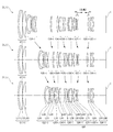
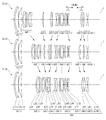
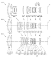
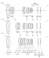
- FIG. 6 is a diagram showing a movement of a lens when the variable power optical system according to Example 1 changes from a wide-angle end state to a telephoto end state.
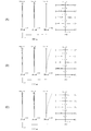
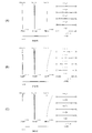
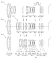
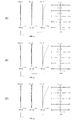
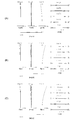
- 2A, 2B, and 2C are aberration diagrams of the variable power optical system according to Example 1 in the wide-angle end state, intermediate focal length state, and telephoto end state, respectively. .. It is a figure which shows the movement of the lens when the variable power optical system which concerns on 2nd Example changes from a wide-angle end state to a telephoto end state.
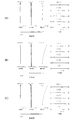
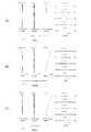
- FIG. 4A, FIG. 4B, and FIG. 4C are aberration diagrams of the variable power optical system according to the second example in the wide-angle end state, intermediate focal length state, and telephoto end state, respectively. ..
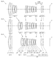
- FIG. 6A, FIG. 6B, and FIG. 6C are aberration diagrams in the wide-angle end state, the intermediate focal length state, and the telephoto end state of the variable power optical system according to the third example, respectively. .. It is a figure which shows the movement of the lens when the variable power optical system which concerns on 4th Example changes from a wide-angle end state to a telephoto end state.
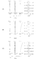
- 8A, 8B, and 8C are graphs showing various aberrations of the variable power optical system according to Example 4 in the wide-angle end state, intermediate focal length state, and telephoto end state, respectively.
- FIG. 10A, 10B, and 10C are graphs showing various aberrations of the variable power optical system according to Example 5 in the wide-angle end state, the intermediate focal length state, and the telephoto end state, respectively. .. It is a figure which shows the movement of the lens at the time of the variable power optical system which concerns on 6th Example changes from a wide-angle end state to a telephoto end state.
- 12A, 12B, and 12C are aberration diagrams of the variable power optical system according to Example 6 in the wide-angle end state, intermediate focal length state, and telephoto end state, respectively. .. It is a figure which shows the movement of a lens when the variable power optical system which concerns on 7th Example changes from a wide-angle end state to a telephoto end state.
- 14A, 14B, and 14C are aberration diagrams of the variable power optical system according to the seventh example in the wide-angle end state, intermediate focal length state, and telephoto end state, respectively. .. It is a figure which shows the structure of the camera provided with the variable power optical system which concerns on this embodiment. 6 is a flowchart showing a method for manufacturing a variable power optical system according to the present embodiment.
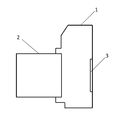
- the camera 1 is a digital camera having a variable power optical system according to this embodiment as a taking lens 2.
- the taking lens 2 In the camera 1, light from an object (subject) (not shown) is condensed by the taking lens 2 and reaches the image sensor 3. Accordingly, the light from the subject is captured by the image sensor 3 and recorded as a subject image in a memory (not shown). In this way, the photographer can photograph the subject with the camera 1.
- the camera may be a mirrorless camera or a single-lens reflex type camera having a quick return mirror.
- variable power optical system ZL (1) as an example of the variable power optical system (zoom lens) ZL according to the present embodiment has a positive refractive power arranged in order from the object side. It has a lens group G1, a second lens group G2 having a negative refractive power, a third lens group G3 having a positive refractive power, and a subsequent lens group GR. At the time of zooming, the distance between adjacent lens groups changes.
- the first lens group G1 is fixed with respect to the image plane during zooming.
- the subsequent lens group GR includes a first focusing lens group having a negative refracting power that moves when focusing and a second focusing lens group that has a positive refracting power that moves when focusing, which are arranged in order from the object side. And a focusing lens group.
- variable power optical system ZL satisfies the following conditional expression (1).
- fF1 focal length of the first focusing lens group
- fF2 focal length of the second focusing lens group
- variable power optical system ZL may be the variable power optical system ZL (2) shown in FIG. 3, the variable power optical system ZL (3) shown in FIG. 5, or the variable power optical system shown in FIG. It may be ZL (4).
- the variable power optical system ZL according to the present embodiment may be the variable power optical system ZL (5) shown in FIG. 9, the variable power optical system ZL (6) shown in FIG. 11, or the variable power shown in FIG.
- the optical system ZL (7) may be used.
- Conditional expression (1) defines the ratio between the focal length of the first focusing lens unit and the focal length of the second focusing lens unit.
- the refracting power of the second focusing lens unit becomes strong, so that it becomes difficult to suppress fluctuations of various aberrations such as spherical aberration during focusing. Become.
- the upper limit of conditional expression (1) is set to 4.50, 4.25, 4.00, 3.75, 3.50, 3.25, 3. It may be set to 0.00, 2.75, 2.50, 2.25, or even 2.00.
- the lower limit of conditional expression (1) is set to 0.85, the effect of this embodiment can be made more reliable.
- the lower limit of conditional expression (1) is set to 0.90, 1.00, 1.10, 1.20, 1.25, 1.28, and It may be set to 1.30.
- variable power optical system ZL satisfies the following conditional expression (2).
- mTF1 the amount of movement of the first focusing lens unit when focusing from an object at infinity to a near object in the telephoto end state (the sign of the amount of movement to the object side is +, and the amount of movement to the image side is The sign is-)
- mTF2 The amount of movement of the second focusing lens group when focusing from an infinitely distant object to a short-distance object in the telephoto end state (the sign of the amount of movement to the object side is +, and the sign of the amount of movement to the image side is -And)
- Conditional expression (2) is the amount of movement of the first focusing lens unit when focusing from an infinity object to a short-distance object (object at the shortest distance) in the telephoto end state, and from the infinity object in the telephoto end state. It defines the ratio to the amount of movement of the second focusing lens unit when focusing on a short-distance object (the closest object).
- conditional expression (2) When the corresponding value of the conditional expression (2) exceeds the upper limit value, the movement amount of the second focusing lens unit becomes large, so that it becomes difficult to suppress variations in various aberrations such as spherical aberration during focusing. Become.
- the upper limit of conditional expression (2) By setting the upper limit of conditional expression (2) to -0.15, the effect of the present embodiment can be made more reliable.
- the upper limits of conditional expression (2) are set to ⁇ 0.18, ⁇ 0.20, ⁇ 0.23, ⁇ 0.25, ⁇ 0.28, It may be set to -0.30, -0.33, -0.35, -0.38, -0.40, or -0.43.
- the corresponding value of the conditional expression (2) When the corresponding value of the conditional expression (2) is less than the lower limit value, the movement amount of the first focusing lens unit becomes large, so that it becomes difficult to suppress variation of various aberrations such as spherical aberration during focusing. Become.
- the lower limit of conditional expression (2) By setting the lower limit of conditional expression (2) to -1.90, the effect of the present embodiment can be made more reliable. In order to further secure the effect of this embodiment, even if the lower limit value of the conditional expression (2) is set to -1.80, -1.70, -1.60, and further -1.50. Good.
- variable power optical system ZL satisfies the following conditional expression (3).
- ⁇ TF1 Lateral magnification of the first focusing lens group when focusing on an object at infinity in the telephoto end state
- ⁇ TF2 Lateral magnification of the second focusing lens group when focusing on an object at infinity at the telephoto end state
- Conditional expression (3) is the lateral magnification of the first focusing lens group when focusing on an object at infinity in the telephoto end state, and the second focusing lens group when focusing on an object at infinity at the telephoto end state. It defines the ratio to the lateral magnification of.
- the lateral magnification of the first focusing lens unit becomes large, so that it becomes difficult to suppress variations in various aberrations such as spherical aberration during focusing. Become.
- the upper limit of conditional expression (3) is set to 0.90, 0.85, 0.80, 0.75, 0.70, 0.65, and It may be set to 0.64.
- the lateral magnification of the second focusing lens unit becomes large, so that it becomes difficult to suppress variations in various aberrations such as spherical aberration during focusing. Become.
- the lower limit of conditional expression (3) is set to 0.15, 0.18, 0.20, 0.22, 0.24, and 0.25. You may set it.
- variable power optical system ZL it is desirable that the first focusing lens unit moves to the image side when focusing from an object at infinity to a near object. This is preferable because fluctuations in spherical aberration and field curvature can be reduced when focusing from an infinitely distant object to a near object.
- variable power optical system ZL it is desirable that the second focusing lens group moves to the object side when focusing from an object at infinity to a near object. This is preferable because fluctuations in spherical aberration and field curvature can be reduced when focusing from an infinitely distant object to a near object.
- variable power optical system ZL According to the present embodiment satisfy the following conditional expression (4). -10.00 ⁇ ( ⁇ TF1 / ⁇ WF1) ⁇ ( ⁇ TF2 / ⁇ WF2) ⁇ 10.00 (4)
- ⁇ TF1 Lateral magnification of the first focusing lens group when focusing on an object at infinity in the telephoto end state
- ⁇ WF1 Lateral magnification of the first focusing lens group when focusing on an object at infinity at the wide-angle end state
- ⁇ TF2 Lateral magnification of the second focusing lens group when focusing on an infinite object in the telephoto end state
- ⁇ WF2 Lateral magnification of the second focusing lens group when focusing on an infinite object in the wide-angle end state
- Conditional expression (4) defines the contribution of the first focusing lens unit and the second focusing lens to the zooming. By satisfying conditional expression (4), it is possible to downsize the lens barrel and satisfactorily correct various aberrations such as field curvature and spherical aberration.
- the corresponding value of the conditional expression (4) is within the above range because fluctuations of spherical aberration and curvature of field at the time of zooming can be suppressed small.
- the upper limit of conditional expression (4) is set to 6.00, 5.00, 4.00, 3.50, 3.00, 2.50, 2. It may be set to 0.00, 1.80, 1.50, or 1.30. Further, by setting the lower limit of conditional expression (4) to ⁇ 8.00, the effect of the present embodiment can be made more reliable.
- the lower limit of conditional expression (4) is set to ⁇ 6.00, ⁇ 5.00, ⁇ 4.00, ⁇ 2.50, ⁇ 1.00, It may be set to -0.50, 0.50, 0.75, or 0.90.
- variable power optical system ZL satisfies the following conditional expression (5).
- Conditional expression (5) defines the ratio between the focal length of the first lens group G1 and the focal length of the second lens group G2.
- conditional expression (5) If the corresponding value of conditional expression (5) exceeds the upper limit value, the refracting power of the second lens group G2 becomes strong, and it becomes difficult to correct coma aberration and spherical aberration.
- the upper limit of conditional expression (5) is set to 4.50, 4.30, 4.00, 3.90, 3.80, and 3.75. You may set it.
- conditional expression (5) When the corresponding value of the conditional expression (5) is below the lower limit value, the refracting power of the first lens group G1 becomes strong, and it becomes difficult to correct coma aberration and spherical aberration.
- the lower limit values of conditional expression (5) are set to 1.90, 2.00, 2.25, 2.40, 2.50, 2.70, and 2. It may be set to 0.80, 2.90, or 3.00.
- variable power optical system ZL satisfies the following conditional expression (6).
- Conditional expression (6) defines the ratio between the focal length of the first lens group G1 and the focal length of the third lens group G3.
- the upper limit values of the conditional expression (6) are set to 2.40, 2.20, 2.00, 1.90, 1.80, 1.70, 1. .60, and may be set to 1.50.
- conditional expression (6) If the corresponding value of the conditional expression (6) is less than the lower limit value, the refractive power of the first lens group G1 becomes strong, and it becomes difficult to correct spherical aberration and coma.
- the lower limit values of conditional expression (6) are set to 0.85, 0.87, 0.90, 0.92, 0.95, 0.98, and It may be set to 1.00.
- variable power optical system ZL it is desirable that the subsequent lens group GR has a fourth lens group G4 and that the following conditional expression (7) is satisfied.
- f1 focal length of the first lens group G1
- f4 focal length of the fourth lens group G4
- Conditional expression (7) defines the ratio between the focal length of the first lens group G1 and the focal length of the fourth lens group G4.
- the refracting power of the fourth lens group G4 becomes strong, and it becomes difficult to correct spherical aberration and coma.
- the upper limit values of the conditional expression (7) are set to 3.60, 3.50, 3.20, 3.00, 2.80, 2.60, 2 It may be set to 0.50, 2.40, or 2.30.
- the lower limit of conditional expression (7) is set to 0.50, 0.80, 1.00, 1.20, 1.40, 1.50, and It may be set to 1.55.
- variable power optical system ZL it is desirable that the third lens group G3 moves to the image side during zooming from the wide-angle end state to the telephoto end state. This makes it possible to satisfactorily correct various aberrations such as spherical aberration, and secure a zoom ratio that satisfies the present embodiment.
- the second lens group G2 has a positive lens that satisfies the following conditional expressions (8) to (10).
- ⁇ dP Abbe number based on the d line of the positive lens
- ndP Refractive index of the positive lens with respect to the d line
- ⁇ gFP Partial dispersion ratio of the positive lens
- the refractive index with respect to the g line of the positive lens is ngP
- nFP is the refractive index for the F line
- nCP is the refractive index for the C line of the positive lens
- ⁇ gFP (ngP-nFP) / (nFP-nCP)
- conditional expression (8) defines an appropriate range of the Abbe's number based on the d-line of the positive lens in the second lens group G2.
- conditional expression (8) If the corresponding value of conditional expression (8) exceeds the upper limit value, it becomes difficult to correct the axial chromatic aberration, which is not preferable.
- the upper limit of conditional expression (8) By setting the upper limit of conditional expression (8) to 32.5, the effect of this embodiment can be made more reliable. In order to further secure the effect of this embodiment, it is preferable to set the upper limit of conditional expression (8) to 31.5.
- conditional expression (8) If the corresponding value of conditional expression (8) is below the lower limit value, it becomes difficult to correct the axial chromatic aberration, which is not preferable.
- the lower limit of conditional expression (8) is set to 22.00, 23.00, 23.50, 24.00, 25.00, and further 26.00. Preferably.
- conditional expression (9) defines an appropriate relationship between the refractive index of the positive lens in the second lens group G2 with respect to the d-line and the Abbe number based on the d-line.
- conditional expression (9) If the corresponding value of the conditional expression (9) deviates from the above range, it becomes difficult to correct the curvature of field, for example, the Petzval sum becomes small, which is not preferable.
- the upper limit of conditional expression (9) By setting the upper limit of conditional expression (9) to 2.10, the effect of this embodiment can be made more reliable. In order to further secure the effect of this embodiment, it is preferable to set the upper limit value of the conditional expression (9) to 2.08, further 2.06.
- the lower limit of conditional expression (9) to 1.84 the effect of the present embodiment can be made more reliable. In order to further secure the effect of this embodiment, it is preferable to set the lower limit of conditional expression (9) to 1.85.
- conditional expression (10) appropriately defines the anomalous dispersion of the positive lens in the second lens group G2.
- conditional expression (10) it is possible to satisfactorily correct the secondary spectrum in addition to the primary achromatization in the correction of chromatic aberration.
- conditional expression (10) If the corresponding value of conditional expression (10) is less than the lower limit value, the anomalous dispersion of the positive lens becomes small, and it becomes difficult to correct chromatic aberration.
- the lower limit of conditional expression (10) By setting the lower limit of conditional expression (10) to 0.704, the effect of this embodiment can be made more reliable. In order to further secure the effect of this embodiment, it is preferable to set the lower limit values of conditional expression (10) to 0.708, 0.710, and 0.715.
- variable power optical system ZL preferably satisfies the following conditional expression (11).
- Conditional expression (11) defines the total angle of view of the variable power optical system ZL in the wide-angle end state. By satisfying the conditional expression (11), it is possible to satisfactorily correct various aberrations such as coma, distortion, and field curvature while having a wide angle of view that satisfies the present embodiment.
- the lower limit of conditional expression (11) By setting the lower limit of conditional expression (11) to 27.00 °, the effect of the present embodiment can be made more reliable. In order to further secure the effect of this embodiment, even if the lower limit value of the conditional expression (11) is set to 29.00 °, 30.00 °, 32.00 °, and 33.00 °. Good.
- the upper limit of conditional expression (11) is set to 45.00 °, 42.00 °, 40.00 °, 38.00 °, 36.00 °, Further, it may be set to 35.00 °.
- variable power optical system ZL satisfies the following conditional expression (12).
- Conditional expression (12) defines the total angle of view of the variable magnification optical system ZL in the telephoto end state.
- it is possible to excellently correct various aberrations such as coma, distortion, and field curvature.
- the upper limit of conditional expression (12) By setting the upper limit of conditional expression (12) to 18.00 °, the effect of the present embodiment can be made more reliable.
- the lower limit of conditional expression (12) is set to 8.00 °, 10.00 °, 11.00 °, and further 12.00 °. Good.
- variable power optical system ZL satisfies the following conditional expression (13).
- BFw Back focus of the variable power optical system ZL in the wide-angle end state
- fw Focal length of the variable power optical system ZL in the wide-angle end state
- Conditional expression (13) defines the ratio of the back focus of the variable power optical system ZL in the wide-angle end state to the focal length of the variable power optical system ZL in the wide-angle end state.
- conditional expression (13) When the corresponding value of the conditional expression (13) exceeds the upper limit value, the back focus becomes too large with respect to the focal length of the variable power optical system ZL in the wide-angle end state, so that various aberrations including coma aberration in the wide-angle end state. Is difficult to correct.
- the upper limit of conditional expression (13) By setting the upper limit of conditional expression (13) to 0.80, the effect of the present embodiment can be made more reliable. In order to further secure the effect of the present embodiment, even if the upper limit of conditional expression (13) is set to 0.75, 0.70, 0.65, 0.60, and even 0.55. Good.
- the corresponding value of the conditional expression (13) is less than the lower limit value, the back focus becomes too small with respect to the focal length of the variable power optical system ZL in the wide-angle end state, so that various aberrations including coma aberration in the wide-angle end state. Is difficult to correct. Further, it becomes difficult to arrange the mechanical member of the lens barrel.
- the lower limit value of the conditional expression (13) may be set to 0.30, 0.35, 0.40, and 0.42.
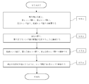
- the manufacturing method of the variable power optical system ZL according to the present embodiment will be outlined with reference to FIG.
- the configuration is such that the distance between adjacent lens groups changes during zooming (step ST2).
- the first lens group G1 is fixed with respect to the image plane.
- the third lens group G3 moves toward the image side along the optical axis.
- the subsequent lens group GR has, in order from the object side, a first focusing lens group having a negative refractive power that moves during focusing, and a second focusing lens group that has a positive refractive power that moves during focusing.
- the focusing lens group is arranged (step ST3).
- each lens is arranged in the lens barrel so as to satisfy at least the conditional expression (1) (step ST4). According to such a manufacturing method, it becomes possible to manufacture a variable power optical system in which various aberrations such as spherical aberration are properly corrected.
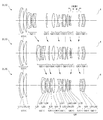
- variable-magnification optical systems ZL ⁇ ZL (1) to ZL (7) ⁇ are at the wide-angle end. It is a figure which shows the movement of the lens at the time of changing from a state to a telephoto end state.
- the moving direction along the optical axis of the lens group that moves during zooming from the wide-angle end state to the telephoto end state is indicated by an arrow.
- the moving direction when the focusing lens group focuses on an object at a short distance from infinity is indicated by an arrow together with the character "focus".
- each lens group is represented by a combination of reference numeral G and a numeral
- each lens is represented by a combination of reference numeral L and a numeral.
- the lens groups and the like are represented independently by using combinations of symbols and numbers for each embodiment. Therefore, even if the same combination of reference numerals and numbers is used between the embodiments, it does not mean that they have the same configuration.
- Tables 1 to 7 are shown below. Of these, Table 1 is the first example, Table 2 is the second example, Table 3 is the third example, Table 4 is the fourth example, and Table 5 is the fifth example. 5th Example, Table 6 is a table showing respective specification data in the 6th Example, and Table 7 is in the 7th Example.
- FNO is the F number
- 2 ⁇ is the angle of view (unit is ° (degrees)
- ⁇ is the half angle of view
- Y is the image height
- TL is the distance from the lens front surface to the final lens surface on the optical axis when focused on infinity
- BF is the image from the final lens surface on the optical axis when focused on infinity.
- the air equivalent distance (back focus) to the surface I is shown. Note that these values are shown for each of the wide-angle end (W), the intermediate focal length (M), and the telephoto end (T) in each variable power state.
- ⁇ gFP represents the partial dispersion ratio of the positive lens in the second lens group.
- mTF1 indicates the amount of movement of the first focusing lens unit when focusing from an infinitely distant object to a short-distance object (object at the closest distance) in the telephoto end state (the sign of the amount of movement to the object side is + , And the sign of the amount of movement to the image side is-).
- mTF2 indicates the amount of movement of the second focusing lens unit when focusing from an infinitely distant object to a short-distance object (shortest-distance object) in the telephoto end state.
- ⁇ TF1 represents the lateral magnification of the first focusing lens unit when focusing on an object at infinity in the telephoto end state.
- ⁇ TF2 represents the lateral magnification of the second focusing lens unit when focusing on an object at infinity in the telephoto end state.
- ⁇ WF1 represents the lateral magnification of the first focusing lens unit when focusing on an object at infinity in the wide-angle end state.
- ⁇ WF2 represents the lateral magnification of the second focusing lens unit when focusing on an object at infinity in the wide-angle end state.
- the surface number indicates the order of the optical surface from the object side along the traveling direction of the light ray, and R represents the radius of curvature of each optical surface (the surface whose center of curvature is located on the image side).
- D is a surface distance that is a distance on the optical axis from each optical surface to the next optical surface (or image surface)
- nd is a refractive index of the material of the optical member with respect to d-line
- ⁇ d is an optical value.
- the Abbe number of the material of the member based on the d-line and ⁇ gF indicate the partial dispersion ratio of the material of the optical member.
- the radius of curvature " ⁇ " indicates a plane or an aperture, and (stop S) indicates an aperture stop.
- the description of the refractive index of air nd 1.0000 is omitted.
- the surface number is marked with * and the radius of curvature R column indicates the paraxial radius of curvature.
- the C of the material of the optical member is C
- the partial dispersion ratio ⁇ gF of the material of the optical member is defined by the following expression (A).
- the [Lens group data] table shows the starting surface (the surface closest to the object) and the focal length of each lens group.
- the table of [Variable spacing data] shows the surface spacing at the surface numbers for which the surface spacing is "variable” in the table showing [Lens specifications].
- W wide-angle end
- M intermediate focal length
- T telephoto end
- f focal length of the entire lens system
- ⁇ indicates the photographing magnification.
- the table of [Values corresponding to conditional expressions] shows the values corresponding to each conditional expression.
- the focal length f, radius of curvature R, surface distance D, and other lengths listed are generally “mm” unless otherwise specified, but the optical system is proportionally enlarged. Alternatively, since the same optical performance can be obtained even if the proportion is reduced, the invention is not limited to this.
- FIG. 1 is a diagram showing the movement of the lens when the variable power optical system according to Example 1 changes from the wide-angle end state to the telephoto end state.
- the variable power optical system ZL (1) according to the first example includes a first lens group G1 having a positive refractive power, a second lens group G2 having a negative refractive power, arranged in order from the object side, and a positive lens group G2.
- the second lens group G2, the third lens group G3, the fifth lens group G5, the seventh lens group G7, and the eighth lens group G8 are separately provided in FIG. Moves in the direction indicated by the arrow, and the distance between adjacent lens groups changes.
- the first lens group G1, the fourth lens group G4, the sixth lens group G6, and the ninth lens group G9 are fixed with respect to the image plane I.
- the fourth lens group G4, the fifth lens group G5, the sixth lens group G6, the seventh lens group G7, the eighth lens group G8, and the ninth lens group G9 are subsequent lens groups. It corresponds to GR.
- the symbol (+) or ( ⁇ ) attached to each lens group symbol indicates the refractive power of each lens group, and this is the same in all the examples below.
- the first lens group G1 includes, in order from the object side, a cemented lens of a negative meniscus lens L11 having a convex surface facing the object side and a plano-convex positive lens L12 having a convex surface facing the object side, and a convex surface facing the object side. And a positive meniscus lens L13 facing the lens.
- the second lens group G2 includes, in order from the object side, a negative meniscus lens L21 having a convex surface facing the object side, a biconcave negative lens L22, a positive meniscus lens L23 having a convex surface facing the object side, and It is composed of a concave negative lens L24.
- the third lens group G3 is composed of a positive meniscus lens L31 having a convex surface directed toward the object side.
- the fourth lens group G4 is composed of a biconvex positive lens L41 and a negative meniscus lens L42 having a convex surface directed toward the object side, which are arranged in order from the object side.
- the fifth lens group G5 is composed of a cemented lens made up of a biconcave negative lens L51 and a biconvex positive lens L52.
- An aperture stop S is disposed on the most object side of the fifth lens group G5, and moves with the fifth lens group G5 during zooming.
- the sixth lens group G6 is a cemented lens of a negative meniscus lens L61 having a convex surface directed toward the object side, a biconvex positive lens L62, and a negative meniscus lens L63 having a concave surface directed toward the object side, which are arranged in order from the object side. And a positive meniscus lens L64 having a convex surface facing the object side.
- the positive lens L62 has an aspherical lens surface on the object side.
- the seventh lens group G7 is composed of, in order from the object side, a positive meniscus lens L71 having a concave surface facing the object side and a negative meniscus lens L72 having a convex surface facing the object side.
- the eighth lens group G8 is composed of a biconvex positive lens L81.
- the ninth lens group G9 is composed of, in order from the object side, a negative meniscus lens L91 having a concave surface facing the object side and a negative meniscus lens L92 having a concave surface facing the object side.
- the negative meniscus lens L91 has an aspherical lens surface on the object side.
- the image plane I is disposed on the image side of the ninth lens group G9. That is, the ninth lens group G9 corresponds to the final lens group.
- the seventh lens group G7 is moved to the image plane I side and the eighth lens group G8 is moved to the object side, thereby changing from a long-distance object to a short-distance object (from an infinite object to a finite object). Is focused. That is, the seventh lens group G7 corresponds to the first focusing lens group, and the eighth lens group G8 corresponds to the second focusing lens group.
- Table 1 below lists values of specifications of the variable power optical system according to the first example.
- 2A, 2B, and 2C are aberration diagrams of the variable power optical system according to Example 1 in the wide-angle end state, intermediate focal length state, and telephoto end state, respectively. ..
- FNO indicates the F number
- Y indicates the image height.
- the spherical aberration diagram shows the F number value corresponding to the maximum aperture
- the astigmatism diagram and the distortion diagram show the maximum image height
- the lateral aberration diagram shows the image height value.
- the solid line shows the sagittal image plane
- the broken line shows the meridional image plane.
- variable magnification optical system according to Example 1 has excellent aberration performance and excellent imaging performance.
- FIG. 3 is a diagram showing the movement of the lens when the variable power optical system according to the second example changes from the wide-angle end state to the telephoto end state.
- the variable power optical system ZL (2) according to the second example includes a first lens group G1 having a positive refractive power, a second lens group G2 having a negative refractive power, arranged in order from the object side, and a positive lens group G2.
- a seventh lens group G7 having negative refractive power At the time of zooming from the wide-angle end state to the telephoto end state, the second lens group G2, the third lens group G3, the fifth lens group G5, and the sixth lens group G6 are individually moved in the directions shown by arrows in FIG. By moving, the distance between the adjacent lens groups changes.
- the first lens group G1, the fourth lens group G4, and the seventh lens group G7 are fixed with respect to the image plane I.
- the lens group including the fourth lens group G4, the fifth lens group G5, the sixth lens group G6, and the seventh lens group G7 corresponds to the subsequent lens group GR.
- the first lens group G1 includes, in order from the object side, a cemented lens of a negative meniscus lens L11 having a convex surface facing the object side and a biconvex positive lens L12, and a positive meniscus lens L13 having a convex surface facing the object side. Composed of and.
- the second lens group G2 includes, in order from the object side, a negative meniscus lens L21 having a convex surface directed toward the object side, a biconcave negative lens L22, a positive meniscus lens L23 having a convex surface directed toward the object side, and an object. And a negative meniscus lens L24 having a concave surface directed to the side.
- the third lens group G3 is composed of a positive meniscus lens L31 having a convex surface directed toward the object side.
- the fourth lens group G4 includes, in order from the object side, a positive meniscus lens L41 having a convex surface directed toward the object side, a positive meniscus lens L42 having a convex surface directed toward the object side, a biconcave negative lens L43, and a biconvex lens.
- An aperture stop S is arranged between the positive meniscus lens L42 and the negative lens L43 in the fourth lens group G4, and moves with the fourth lens group G4 during zooming.
- the lens surface of the positive lens L46 on the object side is an aspherical surface.
- the fifth lens group G5 is composed of a positive meniscus lens L51 having a concave surface facing the object side and a biconcave negative lens L52 arranged in order from the object side.
- the sixth lens group G6 is composed of a biconvex positive lens L61.
- the seventh lens group G7 is composed of a biconcave negative lens L71.
- the negative lens L71 has an aspherical lens surface on the object side.
- the image plane I is disposed on the image side of the seventh lens group G7. That is, the seventh lens group G7 corresponds to the final lens group.
- the fifth lens group G5 is moved to the image plane I side, and the sixth lens group G6 is moved to the object side, thereby changing from a long-distance object to a short-distance object (from an infinite object to a finite object). Is focused. That is, the fifth lens group G5 corresponds to the first focusing lens group, and the sixth lens group G6 corresponds to the second focusing lens group.
- Table 2 below lists values of specifications of the variable power optical system according to the second example.
- FIG. 4A, FIG. 4B, and FIG. 4C are aberration diagrams of the variable power optical system according to the second example in the wide-angle end state, intermediate focal length state, and telephoto end state, respectively. .. It is understood from the various aberration diagrams that the variable power optical system according to Example 2 has the various aberrations well corrected and has excellent imaging performance.
- FIG. 5 is a diagram showing the movement of the lens when the variable power optical system according to the third example changes from the wide-angle end state to the telephoto end state.
- the variable power optical system ZL (3) according to the third example includes a first lens group G1 having a positive refractive power, a second lens group G2 having a negative refractive power, arranged in order from the object side, and a positive lens group G2.
- the first lens group G1, the sixth lens group G6, and the tenth lens group G10 are fixed with respect to the image plane I.
- the lens group corresponds to the subsequent lens group GR.
- the first lens group G1 includes, in order from the object side, a cemented lens of a negative meniscus lens L11 having a convex surface facing the object side and a biconvex positive lens L12, and a positive meniscus lens L13 having a convex surface facing the object side. Composed of and.
- the second lens group G2 includes, in order from the object side, a negative meniscus lens L21 having a convex surface facing the object side, a biconcave negative lens L22, a positive meniscus lens L23 having a convex surface facing the object side, and It is composed of a concave negative lens L24.
- the third lens group G3 is composed of a positive meniscus lens L31 having a convex surface directed toward the object side.
- the fourth lens group G4 includes a biconvex positive lens L41 and a positive meniscus lens L42 having a convex surface facing the object side, which are arranged in order from the object side.
- the fifth lens group G5 is composed of a cemented lens made up of a biconcave negative lens L51 and a biconvex positive lens L52.
- An aperture stop S is disposed on the most object side of the fifth lens group G5, and moves with the fifth lens group G5 during zooming.
- the sixth lens group G6 is a cemented lens of a negative meniscus lens L61 having a convex surface directed toward the object side, a biconvex positive lens L62, and a negative meniscus lens L63 having a concave surface directed toward the object side, which are arranged in order from the object side. And a positive meniscus lens L64 having a convex surface facing the object side.
- the positive lens L62 has an aspherical lens surface on the object side.
- the seventh lens group G7 is composed of, in order from the object side, a biconvex positive lens L71 and a negative meniscus lens L72 having a convex surface directed toward the object side.
- the eighth lens group G8 is composed of a positive meniscus lens L81 having a convex surface directed toward the object side.
- the ninth lens group G9 is composed of a positive meniscus lens L91 having a concave surface facing the object side.
- the positive meniscus lens L91 has an aspherical lens surface on the object side.
- the tenth lens group G10 is composed of a biconcave negative lens L101.
- the image plane I is disposed on the image side of the tenth lens group G10. That is, the tenth lens group G10 corresponds to the final lens group.
- the seventh lens group G7 is moved to the image plane I side and the eighth lens group G8 is moved to the object side, thereby changing from a long-distance object to a short-distance object (from an infinite object to a finite object). Is focused. That is, the seventh lens group G7 corresponds to the first focusing lens group, and the eighth lens group G8 corresponds to the second focusing lens group.
- Table 3 below shows the values of specifications of the variable power optical system according to the third example.
- FIG. 6A, FIG. 6A, and FIG. 6C are aberration diagrams in the wide-angle end state, the intermediate focal length state, and the telephoto end state of the variable power optical system according to the third example, respectively. .. It is understood from the various aberration diagrams that the variable power optical system according to Example 3 has the various aberrations well corrected and has excellent imaging performance.
- FIG. 7 is a diagram showing the movement of the lens when the variable power optical system according to the fourth example changes from the wide-angle end state to the telephoto end state.
- the variable power optical system ZL (4) according to the fourth example includes a first lens group G1 having a positive refractive power, a second lens group G2 having a negative refractive power, arranged in order from the object side, and a positive lens group G2.
- a seventh lens group G7 having a positive refractive power and an eighth lens group G8 having a negative refractive power are separately provided in FIG. Moves in the direction indicated by the arrow, and the distance between adjacent lens groups changes. It should be noted that during zooming, the first lens group G1, the fifth lens group G5, and the eighth lens group G8 are fixed with respect to the image plane I.
- the lens group including the fourth lens group G4, the fifth lens group G5, the sixth lens group G6, the seventh lens group G7, and the eighth lens group G8 corresponds to the subsequent lens group GR.
- the first lens group G1 includes, in order from the object side, a cemented lens of a negative meniscus lens L11 having a convex surface facing the object side and a biconvex positive lens L12, and a positive meniscus lens L13 having a convex surface facing the object side. Composed of and.
- the second lens group G2 includes, in order from the object side, a negative meniscus lens L21 having a convex surface facing the object side, a biconcave negative lens L22, a positive meniscus lens L23 having a convex surface facing the object side, and It is composed of a concave negative lens L24.
- the third lens group G3 is composed of a positive meniscus lens L31 having a convex surface directed toward the object side.
- the fourth lens group G4 includes a biconvex positive lens L41 and a positive meniscus lens L42 having a convex surface facing the object side, which are arranged in order from the object side.
- the fifth lens group G5 includes, in order from the object side, a cemented lens of a biconcave negative lens L51 and a biconvex positive lens L52, a negative meniscus lens L53 having a convex surface directed toward the object side, and a biconvex lens. It is composed of a cemented lens of a positive lens L54 having a shape and a negative meniscus lens L55 having a concave surface facing the object side, and a positive meniscus lens L56 having a convex surface facing the object side.
- An aperture stop S is disposed on the most object side of the fifth lens group G5, and is fixed to the image plane I together with the fifth lens group G5 during zooming.
- the positive lens L54 has an aspherical lens surface on the object side.
- the sixth lens group G6 is composed of, in order from the object side, a positive meniscus lens L61 having a concave surface facing the object side and a negative meniscus lens L62 having a convex surface facing the object side.
- the seventh lens group G7 is composed of a biconvex positive lens L71.
- the eighth lens group G8 is composed of, in order from the object side, a negative meniscus lens L81 having a convex surface facing the object side and a negative meniscus lens L82 having a concave surface facing the object side.
- the negative meniscus lens L81 has an aspherical lens surface on the object side.
- the image plane I is disposed on the image side of the eighth lens group G8. That is, the eighth lens group G8 corresponds to the final lens group.
- the sixth lens group G6 is moved to the image plane I side and the seventh lens group G7 is moved to the object side, thereby changing from a long-distance object to a short-distance object (from an infinite object to a finite object). Is focused. That is, the sixth lens group G6 corresponds to the first focusing lens group, and the seventh lens group G7 corresponds to the second focusing lens group.
- Table 4 below shows values of specifications of the variable power optical system according to the fourth example.
- FIG. 8A, 8B, and 8C are graphs showing various aberrations of the variable power optical system according to Example 4 in the wide-angle end state, intermediate focal length state, and telephoto end state, respectively. .. It is understood from the various aberration diagrams that the variable power optical system according to Example 4 has the various aberrations well corrected and has excellent imaging performance.
- FIG. 9 is a diagram showing the movement of the lens when the variable power optical system according to the fifth example changes from the wide-angle end state to the telephoto end state.
- the variable power optical system ZL (5) according to the fifth example includes a first lens group G1 having a positive refractive power, a second lens group G2 having a negative refractive power, and a positive lens group arranged in order from the object side.
- the second lens group G2, the third lens group G3, the fifth lens group G5, the seventh lens group G7, and the eighth lens group G8 are separately provided in FIG. Moves in the direction indicated by the arrow, and the distance between adjacent lens groups changes.
- the first lens group G1, the fourth lens group G4, the sixth lens group G6, and the ninth lens group G9 are fixed with respect to the image plane I.
- the fourth lens group G4, the fifth lens group G5, the sixth lens group G6, the seventh lens group G7, the eighth lens group G8, and the ninth lens group G9 are subsequent lens groups. It corresponds to GR.
- the first lens group G1 includes, in order from the object side, a cemented lens of a negative meniscus lens L11 having a convex surface facing the object side and a biconvex positive lens L12, and a positive meniscus lens L13 having a convex surface facing the object side. Composed of and.
- the second lens group G2 includes, in order from the object side, a negative meniscus lens L21 having a convex surface directed toward the object side, a biconvex positive lens L22, a biconcave negative lens L23, and a concave surface directed toward the object side. And a negative meniscus lens L24 facing the lens.
- the third lens group G3 is composed of a positive meniscus lens L31 having a convex surface directed toward the object side.
- the fourth lens group G4 is composed of a positive meniscus lens L41 having a convex surface directed toward the object side and a biconvex positive lens L42 arranged in order from the object side.
- the fifth lens group G5 is composed of a cemented lens of a biconcave negative lens L51 and a positive meniscus lens L52 having a convex surface facing the object side.
- An aperture stop S is disposed on the most object side of the fifth lens group G5, and moves with the fifth lens group G5 during zooming.
- the sixth lens group G6 includes, in order from the object side, a negative meniscus lens L61 having a convex surface directed toward the object side, a biconvex positive lens L62, and a positive meniscus lens L63 having a convex surface directed toward the object side. To be done.
- the image-side lens surface of the positive lens L62 is an aspherical surface.
- the seventh lens group G7 is composed of a positive meniscus lens L71 with a concave surface facing the object side and a biconcave negative lens L72, which are arranged in order from the object side.
- the eighth lens group G8 is composed of a biconvex positive lens L81.
- the ninth lens group G9 is composed of a biconcave negative lens L91.
- the image plane I is disposed on the image side of the ninth lens group G9. That is, the ninth lens group G9 corresponds to the final lens group.
- the seventh lens group G7 is moved to the image plane I side and the eighth lens group G8 is moved to the object side, thereby changing from a long-distance object to a short-distance object (from an infinite object to a finite object). Is focused. That is, the seventh lens group G7 corresponds to the first focusing lens group, and the eighth lens group G8 corresponds to the second focusing lens group.
- Table 5 lists values of specifications of the variable power optical system according to the fifth example.
- 10A, 10B, and 10C are graphs showing various aberrations of the variable power optical system according to Example 5 in the wide-angle end state, the intermediate focal length state, and the telephoto end state, respectively. .. It is understood from the various aberration diagrams that the variable power optical system according to the fifth example has various aberrations favorably corrected and has excellent imaging performance.
- FIG. 11 is a diagram showing the movement of the lens when the zoom optical system according to Example 6 changes from the wide-angle end state to the telephoto end state.
- the variable power optical system ZL (6) according to Example 6 has a first lens group G1 having a positive refractive power, a second lens group G2 having a negative refractive power, and a positive lens group arranged in order from the object side.
- the second lens group G2, the third lens group G3, the fifth lens group G5, the seventh lens group G7, and the eighth lens group G8 are separately provided in FIG. Moves in the direction indicated by the arrow, and the distance between adjacent lens groups changes.
- the first lens group G1, the fourth lens group G4, the sixth lens group G6, and the ninth lens group G9 are fixed with respect to the image plane I.
- the fourth lens group G4, the fifth lens group G5, the sixth lens group G6, the seventh lens group G7, the eighth lens group G8, and the ninth lens group G9 are subsequent lens groups. It corresponds to GR.
- the first lens group G1 includes, in order from the object side, a cemented lens of a negative meniscus lens L11 having a convex surface facing the object side and a biconvex positive lens L12, and a positive meniscus lens L13 having a convex surface facing the object side. Composed of and.
- the second lens group G2 includes, in order from the object side, a negative meniscus lens L21 having a convex surface facing the object side, a biconcave negative lens L22, a positive meniscus lens L23 having a convex surface facing the object side, and It is composed of a concave negative lens L24.
- the third lens group G3 is composed of a positive meniscus lens L31 having a convex surface directed toward the object side.
- the fourth lens group G4 is composed of a biconvex positive lens L41.
- the positive lens L41 has an aspherical lens surface on the object side.
- the fifth lens group G5 is composed of a cemented lens made up of a biconcave negative lens L51 and a biconvex positive lens L52.
- An aperture stop S is disposed on the most object side of the fifth lens group G5, and moves with the fifth lens group G5 during zooming.
- the sixth lens group G6 is a cemented lens of a negative meniscus lens L61 having a convex surface directed toward the object side, a biconvex positive lens L62, and a negative meniscus lens L63 having a concave surface directed toward the object side, which are arranged in order from the object side. And a positive meniscus lens L64 having a convex surface facing the object side.
- the positive lens L62 has an aspherical lens surface on the object side.
- the seventh lens group G7 is composed of a biconvex positive lens L71 and a biconcave negative lens L72, which are arranged in order from the object side.
- the eighth lens group G8 is composed of a biconvex positive lens L81.
- the ninth lens group G9 is composed of, in order from the object side, a biconcave negative lens L91 and a negative meniscus lens L92 having a concave surface facing the object side.
- the negative lens L91 has an aspherical lens surface on the object side.
- the image plane I is disposed on the image side of the ninth lens group G9. That is, the ninth lens group G9 corresponds to the final lens group.
- the seventh lens group G7 is moved to the image plane I side and the eighth lens group G8 is moved to the object side, thereby changing from a long-distance object to a short-distance object (from an infinite object to a finite object). Is focused. That is, the seventh lens group G7 corresponds to the first focusing lens group, and the eighth lens group G8 corresponds to the second focusing lens group.
- Table 6 below lists values of specifications of the variable power optical system according to the sixth example.
- 12A, 12B, and 12C are aberration diagrams of the variable power optical system according to Example 6 in the wide-angle end state, intermediate focal length state, and telephoto end state, respectively. .. It is understood from the various aberration diagrams that the variable power optical system of the sixth example has the various aberrations corrected well and has excellent imaging performance.
- FIG. 13 is a diagram showing the movement of the lens when the zoom optical system according to Example 7 changes from the wide-angle end state to the telephoto end state.
- the variable power optical system ZL (7) according to Example 7 has a first lens group G1 having a positive refractive power, a second lens group G2 having a negative refractive power, and a positive lens group arranged in order from the object side.
- the second lens group G2, the third lens group G3, the fourth lens group G4, and the fifth lens group G5 are separately moved in the directions shown by the arrows in FIG. By moving, the distance between the adjacent lens groups changes.
- the first lens group G1 and the sixth lens group G6 are fixed with respect to the image plane I during zooming.
- the lens group including the fourth lens group G4, the fifth lens group G5, and the sixth lens group G6 corresponds to the subsequent lens group GR.
- the first lens group G1 includes, in order from the object side, a cemented lens of a negative meniscus lens L11 having a convex surface facing the object side and a biconvex positive lens L12, and a positive meniscus lens L13 having a convex surface facing the object side. Composed of and.
- the second lens group G2 includes, in order from the object side, a negative meniscus lens L21 having a convex surface directed toward the object side, a biconcave negative lens L22, a positive meniscus lens L23 having a convex surface directed toward the object side, and an object. And a negative meniscus lens L24 having a concave surface directed to the side.
- the third lens group G3 includes, in order from the object side, a positive meniscus lens L31 having a convex surface directed toward the object side, a positive meniscus lens L32 having a convex surface directed toward the object side, and a biconvex positive lens L33.
- An aperture stop S is provided between the positive lens L33 and the negative lens L34 in the third lens group G3, and moves with the third lens group G3 during zooming.
- the object-side lens surface of the positive lens L37 is an aspherical surface.
- the fourth lens group G4 is composed of a positive meniscus lens L41 having a concave surface facing the object side and a biconcave negative lens L42, which are arranged in order from the object side.
- the fifth lens group G5 is composed of a biconvex positive lens L51.
- the sixth lens group G6 is composed of a negative meniscus lens L61 having a concave surface facing the object side.
- the negative meniscus lens L61 has an aspherical lens surface on the object side.
- the image plane I is disposed on the image side of the sixth lens group G6. That is, the sixth lens group G6 corresponds to the final lens group.
- the fourth lens group G4 is moved to the image plane I side and the fifth lens group G5 is moved to the object side, thereby changing from a long-distance object to a short-distance object (from an infinite object to a finite object). Is focused. That is, the fourth lens group G4 corresponds to the first focusing lens group, and the fifth lens group G5 corresponds to the second focusing lens group.
- Table 7 below lists values of specifications of the variable power optical system according to the seventh example.
- variable power optical system 14A, 14B, and 14C are aberration diagrams of the variable power optical system according to the seventh example in the wide-angle end state, intermediate focal length state, and telephoto end state, respectively. .. It is understood from the various aberration diagrams that the variable power optical system of the seventh example has various aberrations corrected well and has excellent imaging performance.
- each embodiment it is possible to realize a variable power optical system in which various aberrations such as spherical aberration are favorably corrected.
- each of the above-mentioned embodiments shows a specific example of the present invention, and the present invention is not limited thereto.
- variable power optical system As the numerical examples of the variable power optical system, the configurations of the 6-group, 7-group, 8-group, 9-group, and 10-group configuration are shown, but the present application is not limited to this, and other group configurations (for example, 5 group and It is also possible to construct a variable power optical system of 11 groups or the like. Specifically, a configuration may be adopted in which a lens or a lens group is added to the most object side or most image plane side of the variable power optical system.
- the lens group refers to a portion having at least one lens, which is separated by an air gap that changes during zooming.
- the lens surface may be a spherical surface, a flat surface, or an aspherical surface.
- lens processing and assembly adjustment are facilitated, and deterioration of optical performance due to an error in processing and assembly adjustment can be prevented, which is preferable. Further, even if the image plane is deviated, the drawing performance is less deteriorated, which is preferable.
- the aspherical surface is an aspherical surface formed by grinding, a glass mold aspherical surface formed by molding glass into an aspherical shape, or a composite type aspherical surface formed by resin forming an aspherical surface on the glass surface. Either is fine.
- the lens surface may be a diffractive surface, and the lens may be a gradient index lens (GRIN lens) or a plastic lens.
- each lens surface may be coated with an antireflection film having a high transmittance in a wide wavelength range in order to reduce flare and ghost and achieve high contrast optical performance.
- flare and ghost can be reduced and high optical performance with high contrast can be achieved.
Landscapes
- Physics & Mathematics (AREA)
- General Physics & Mathematics (AREA)
- Optics & Photonics (AREA)
- Nonlinear Science (AREA)
- Lenses (AREA)
Abstract
Description
0.80<(-fF1)/fF2<5.00
但し、fF1:前記第1合焦レンズ群の焦点距離
fF2:前記第2合焦レンズ群の焦点距離
0.80<(-fF1)/fF2<5.00
但し、fF1:前記第1合焦レンズ群の焦点距離
fF2:前記第2合焦レンズ群の焦点距離
但し、fF1:第1合焦レンズ群の焦点距離
fF2:第2合焦レンズ群の焦点距離
但し、mTF1:望遠端状態において無限遠物体から近距離物体へ合焦する際の第1合焦レンズ群の移動量(物体側への移動量の符号を+とし、像側への移動量の符号を-とする)
mTF2:望遠端状態において無限遠物体から近距離物体へ合焦する際の第2合焦レンズ群の移動量(物体側への移動量の符号を+とし、像側への移動量の符号を-とする)
但し、βTF1:望遠端状態において無限遠物体に合焦する場合の第1合焦レンズ群の横倍率
βTF2:望遠端状態において無限遠物体に合焦する場合の第2合焦レンズ群の横倍率
-10.00<(βTF1/βWF1)×(βTF2/βWF2)<10.00 ・・・(4)
但し、βTF1:望遠端状態において無限遠物体に合焦する場合の第1合焦レンズ群の横倍率
βWF1:広角端状態において無限遠物体に合焦する場合の第1合焦レンズ群の横倍率
βTF2:望遠端状態において無限遠物体に合焦する場合の第2合焦レンズ群の横倍率
βWF2:広角端状態において無限遠物体に合焦する場合の第2合焦レンズ群の横倍率
但し、f1:第1レンズ群G1の焦点距離
f2:第2レンズ群G2の焦点距離
但し、f1:第1レンズ群G1の焦点距離
但し、f1:第1レンズ群G1の焦点距離
f4:第4レンズ群G4の焦点距離
1.83<ndP+(0.01425×νdP)<2.12・・・(9)
0.702<θgFP+(0.00316×νdP) ・・・(10)
但し、νdP:正レンズのd線を基準とするアッベ数
ndP:正レンズのd線に対する屈折率
θgFP:正レンズの部分分散比であり、正レンズのg線に対する屈折率をngPとし、正レンズのF線に対する屈折率をnFPとし、正レンズのC線に対する屈折率をnCPとしたとき、次式で定義される
θgFP=(ngP-nFP)/(nFP-nCP)
なお、正レンズのd線を基準とするアッベ数νdPは、次式で定義される
νdP=(ndP-1)/(nFP-nCP)
但し、2ωw:広角端状態における変倍光学系ZLの全画角
但し、2ωt:望遠端状態における変倍光学系ZLの全画角
但し、BFw:広角端状態における変倍光学系ZLのバックフォーカス
fw:広角端状態における変倍光学系ZLの焦点距離
第1実施例について、図1~図2および表1を用いて説明する。図1は、第1実施例に係る変倍光学系が広角端状態から望遠端状態に変化する際のレンズの動きを示す図である。第1実施例に係る変倍光学系ZL(1)は、物体側から順に並んだ、正の屈折力を有する第1レンズ群G1と、負の屈折力を有する第2レンズ群G2と、正の屈折力を有する第3レンズ群G3と、正の屈折力を有する第4レンズ群G4と、負の屈折力を有する第5レンズ群G5と、正の屈折力を有する第6レンズ群G6と、負の屈折力を有する第7レンズ群G7と、正の屈折力を有する第8レンズ群G8と、負の屈折力を有する第9レンズ群G9とから構成される。広角端状態から望遠端状態への変倍の際、第2レンズ群G2、第3レンズ群G3、第5レンズ群G5、第7レンズ群G7、および第8レンズ群G8は、別個に図1の矢印で示す方向に移動し、隣り合う各レンズ群の間隔が変化する。なお、変倍の際、第1レンズ群G1、第4レンズ群G4、第6レンズ群G6、および第9レンズ群G9は、像面Iに対して固定される。第4レンズ群G4と、第5レンズ群G5と、第6レンズ群G6と、第7レンズ群G7と、第8レンズ群G8と、第9レンズ群G9とからなるレンズ群は、後続レンズ群GRに該当する。各レンズ群記号に付けている符号(+)もしくは(-)は各レンズ群の屈折力を示し、このことは以下の全ての実施例でも同様である。
[全体諸元]
変倍比 2.74
θgFP=0.6319
mTF1=-11.525
mTF2=11.525
βTF1=0.514
βTF2=1.472
βWF1=0.515
βWF2=1.472
W M T
FNO 2.88277 2.8637 2.87906
2ω 33.79332 17.81742 12.27158
Y 21.70 21.70 21.70
TL 199.88619 199.88619 199.88619
BF 32.5469 32.5469 32.5469
[レンズ諸元]
面番号 R D nd νd θgF
1 116.34563 2.80 2.00100 29.12
2 85.133 9.70 1.49782 82.57
3 ∞ 0.10
4 92.01324 7.70 1.43385 95.25
5 696.98757 D5(可変)
6 58.77 1.90 1.60300 65.44
7 31.87745 10.30
8 -186.53352 1.60 1.49782 82.57
9 105.34866 0.80
10 41.08366 3.70 1.66382 27.35 0.6319
11 64.00891 5.50
12 -71.62319 1.90 1.49782 82.57
13 88.67881 D13(可変)
14 69.46271 3.20 1.94595 17.98
15 201.8299 D15(可変)
16 126.26563 4.70 1.49782 82.57
17 -126.26563 0.10
18 47.66354 3.85 1.49782 82.57
19 122.86616 D19(可変)
20 ∞ 3.50 (絞りS)
21 -84.82141 1.80 1.92286 20.88
22 52.171 5.00 1.49782 82.57
23 -170.93248 D23(可変)
24 111.64091 1.70 1.85026 32.35
25 60.55636 2.00
26* 58.68256 7.70 1.59306 66.97
27 -55.839 1.70 1.62004 36.4
28 -95.85894 1.30
29 58.0393 2.70 1.80100 34.92
30 135.30037 D30(可変)
31 -369.28597 2.00 1.94595 17.98
32 -98.65201 0.80
33 1344.92022 1.25 1.71300 53.96
34 37.13115 D34(可変)
35 119.39985 3.85 1.90265 35.77
36 -119.39985 D36(可変)
37* -83.23047 1.90 1.51696 64.14
38 -335.27926 4.10
39 -54.71091 1.90 1.56384 60.71
40 -276.64763 BF
[非球面データ]
第26面
κ=0.00,A4=-2.00E-06,A6=8.31E-10
A8=-6.83E-12,A10=2.63E-14,A12=-3.55E-17
第37面
κ=0.00,A4=1.18E-06,A6=1.63E-09
A8=-7.32E-12,A10=2.41E-14,A12=-2.65E-17
[レンズ群データ]
群 始面 焦点距離
G1 1 147.97696
G2 6 -40.5909
G3 14 110.66613
G4 16 69.76371
G5 20 -62.56946
G6 24 56.88582
G7 31 -87.28124
G8 35 66.64828
G9 37 -76.28082
[可変間隔データ]
W M T W M T
無限遠 無限遠 無限遠 近距離 近距離 近距離
f 71.50119 135 196 ― ― ―
β ― ― ― -0.08318 -0.14416 -0.19832
D5 1.59716 33.49859 49.53103 1.59716 33.49859 49.53103
D13 37.80333 11.65214 1.60516 37.80333 11.65214 1.60516
D15 14.09965 8.34942 2.36395 14.09965 8.34942 2.36395
D19 4.24982 7.0795 8.12305 4.24982 7.0795 8.12305
D23 5.35666 2.52698 1.48342 5.35666 2.52698 1.48342
D30 3.81632 6.22894 4.10722 5.10137 11.89468 15.63265
D34 28.12371 22.59291 27.70989 24.58984 10.97816 4.65903
D36 3.7896 6.90778 3.91252 6.03843 12.8568 15.43795
[条件式対応値]
条件式(1) (-fF1)/fF2=1.31
条件式(2) mTF1/mTF2=-1.000
条件式(3) βTF1/βTF2=0.349
条件式(4) (βTF1/βWF1)×(βTF2/βWF2)=0.996
条件式(5) f1/(-f2)=3.65
条件式(6) f1/f3=1.34
条件式(7) f1/f4=2.12
条件式(8) νdP=27.35
条件式(9) ndP+(0.01425×νdP)=2.0536
条件式(10) θgFP+(0.00316×νdP)=0.7183
条件式(11) 2ωw=33.79°
条件式(12) 2ωt=12.27°
条件式(13) BFw/fw=0.46
第2実施例について、図3~図4および表2を用いて説明する。図3は、第2実施例に係る変倍光学系が広角端状態から望遠端状態に変化する際のレンズの動きを示す図である。第2実施例に係る変倍光学系ZL(2)は、物体側から順に並んだ、正の屈折力を有する第1レンズ群G1と、負の屈折力を有する第2レンズ群G2と、正の屈折力を有する第3レンズ群G3と、正の屈折力を有する第4レンズ群G4と、負の屈折力を有する第5レンズ群G5と、正の屈折力を有する第6レンズ群G6と、負の屈折力を有する第7レンズ群G7とから構成される。広角端状態から望遠端状態への変倍の際、第2レンズ群G2、第3レンズ群G3、第5レンズ群G5、および第6レンズ群G6は、別個に図3の矢印で示す方向に移動し、隣り合う各レンズ群の間隔が変化する。なお、変倍の際、第1レンズ群G1、第4レンズ群G4、および第7レンズ群G7は、像面Iに対して固定される。第4レンズ群G4と、第5レンズ群G5と、第6レンズ群G6と、第7レンズ群G7とからなるレンズ群は、後続レンズ群GRに該当する。
[全体諸元]
変倍比 2.74
θgFP=0.6319
mTF1=-11.541
mTF2=11.541
βTF1=0.413
βTF2=1.463
βWF1=0.444
βWF2=1.463
W M T
FNO 2.87938 2.83556 2.81768
2ω 33.81302 17.80714 12.26884
Y 21.70 21.70 21.70
TL 196.12284 196.12284 196.12284
BF 36.61267 36.61267 36.61267
[レンズ諸元]
面番号 R D nd νd θgF
1 108.74314 2.8 1.95000 31.13
2 80.29769 9.7 1.49782 82.57
3 -691.77549 0.1
4 93.78423 7.7 1.43385 95.23
5 338.64045 D5(可変)
6 71.48912 1.9 1.59349 67.89
7 30.17301 9.4
8 -137.03151 1.6 1.49782 82.57
9 93.66474 0.8
10 44.41047 3.94815 1.66382 27.35 0.6319
11 87.61105 5.59008
12 -54.89519 1.9 1.49782 82.57
13 -689.02421 D13(可変)
14 75.42635 4.5 1.94595 30.42
15 490.04562 D15(可変)
16 94.04866 4 1.49782 59.34
17 1181.8169 0.1
18 56.70631 4 1.49782 69.79
19 243.15543 4.5
20 ∞ 3.5 (絞りS)
21 -180.79776 1.8 1.92286 29.82
22 38.61345 4.2 1.49782 67.44
23 -792.77195 4.35979
24 479.73489 1.7 1.80518 22.51
25 75.80342 2
26* 58.49695 7.7 1.59306 67
27 -63.34766 1.7 1.60342 46.96
28 -90.09789 1.3
29 66.31481 2.5 1.80400 44.63
30 153.3585 D30(可変)
31 -130.80634 2.2 1.94594 17.98
32 -67.89935 0.8
33 -163.52036 1.25 1.56883 31.71
34 37.07534 D34(可変)
35 66.52215 4.75 1.80100 48.75
36 -175.782 D36(可変)
37* -73.66538 1.9 1.71999 82.57
38 282.5465 BF
[非球面データ]
第26面
κ=0.00,A4=-2.17E-06,A6=1.23E-09
A8=-8.20E-12,A10=2.53E-14,A12=-2.96E-17
第37面
κ=0.00,A4=9.91E-08,A6=2.50E-09
A8=-1.38E-11,A10=4.59E-14,A12=-5.72E-17
[レンズ群データ]
群 始面 焦点距離
G1 1 139.63445
G2 6 -43.68068
G3 14 93.7469
G4 16 86.63044
G5 31 -83.20858
G6 35 60.77856
G7 37 -80.9748
[可変間隔データ]
W M T W M T
無限遠 無限遠 無限遠 近距離 近距離 近距離
f 71.49616 135 196.00002 ― ― ―
β ― ― ― -0.08386 -0.14611 -0.20261
D5 1.98083 33.88478 49.73838 1.98083 33.88478 49.73838
D13 47.67943 16.00066 1.60866 47.67943 16.00066 1.60866
D15 2.53884 2.31366 0.85206 2.53884 2.31366 0.85206
D30 6.84927 7.75031 3.99572 8.37353 13.43196 15.53626
D34 26.8749 21.64199 27.84545 23.36912 9.9946 4.76438
D36 6.00155 10.33343 7.88455 7.98308 16.29916 19.42509
[条件式対応値]
条件式(1) (-fF1)/fF2=1.37
条件式(2) mTF1/mTF2=-1.000
条件式(3) βTF1/βTF2=0.282
条件式(4) (βTF1/βWF1)×(βTF2/βWF2)=0.930
条件式(5) f1/(-f2)=3.20
条件式(6) f1/f3=1.49
条件式(7) f1/f4=1.61
条件式(8) νdP=27.35
条件式(9) ndP+(0.01425×νdP)=2.0536
条件式(10) θgFP+(0.00316×νdP)=0.7183
条件式(11) 2ωw=33.81°
条件式(12) 2ωt=12.27°
条件式(13) BFw/fw=0.51
第3実施例について、図5~図6および表3を用いて説明する。図5は、第3実施例に係る変倍光学系が広角端状態から望遠端状態に変化する際のレンズの動きを示す図である。第3実施例に係る変倍光学系ZL(3)は、物体側から順に並んだ、正の屈折力を有する第1レンズ群G1と、負の屈折力を有する第2レンズ群G2と、正の屈折力を有する第3レンズ群G3と、正の屈折力を有する第4レンズ群G4と、負の屈折力を有する第5レンズ群G5と、正の屈折力を有する第6レンズ群G6と、負の屈折力を有する第7レンズ群G7と、正の屈折力を有する第8レンズ群G8と、正の屈折力を有する第9レンズ群G9と、負の屈折力を有する第10レンズ群G10とから構成される。広角端状態から望遠端状態への変倍の際、第2レンズ群G2、第3レンズ群G3、第4レンズ群G4、第5レンズ群G5、第7レンズ群G7、第8レンズ群G8、および第9レンズ群G9は、別個に図5の矢印で示す方向に移動し、隣り合う各レンズ群の間隔が変化する。なお、変倍の際、第1レンズ群G1、第6レンズ群G6、および第10レンズ群G10は、像面Iに対して固定される。第4レンズ群G4と、第5レンズ群G5と、第6レンズ群G6と、第7レンズ群G7と、第8レンズ群G8と、第9レンズ群G9と、第10レンズ群G10とからなるレンズ群は、後続レンズ群GRに該当する。
[全体諸元]
変倍比 2.74
θgFP=0.6319
mTF1=-14.058
mTF2=19.682
βTF1=0.520
βTF2=0.829
βWF1=0.473
βWF2=0.810
W M T
FNO 2.8471 2.86934 2.91965
2ω 33.70556 17.86124 12.26972
Y 21.70 21.70 21.70
TL 207.00792 207.00792 207.00792
Bf 32.57205 32.57205 32.57205
[レンズ諸元]
面番号 R D nd νd θgF
1 101.99194 2.80 2.00100 29.12
2 78.37407 9.70 1.49782 82.57
3 -1022.4124 0.10
4 75.80458 7.70 1.43385 95.23
5 278.09823 D5(可変)
6 67.03073 1.90 1.60300 65.44
7 29.65154 7.20
8 -4189.1769 1.60 1.49782 82.57
9 72.21235 2.92
10 41.05723 3.70 1.66382 27.35 0.6319
11 51.79281 6.99
12 -47.57525 1.90 1.49782 82.57
13 876.17776 D13(可変)
14 75.45331 3.20 1.94594 17.98
15 263.87074 D15(可変)
16 99.38463 4.70 1.49782 82.57
17 -385.66566 0.10
18 69.30883 3.85 1.49782 82.57
19 1544.1877 D19(可変)
20 ∞ 3.50 (絞りS)
21 -84.39308 1.80 1.92286 20.88
22 76.70869 5.00 1.49782 82.57
23 -157.06149 D23(可変)
24 168.47838 1.70 1.85026 32.35
25 77.42169 2.00
26* 59.12213 7.70 1.59349 67
27 -51.6115 1.70 1.62004 36.4
28 -89.79626 1.30
29 87.29534 2.70 1.80100 34.92
30 136.2385 D30(可変)
31 627.77024 2.00 1.94594 17.98
32 -206.69697 0.80
33 386.92798 1.25 1.71300 53.96
34 42.23229 D34(可変)
35 66.92449 4.00 1.90265 35.77
36 418.69787 D36(可変)
37* -553.02647 3.00 1.55518 71.49
38 -77.65664 D38(可変)
39 -70.45081 1.90 1.56384 60.71
40 88.47517 BF
[非球面データ]
第26面
κ=0.00,A4=-2.06E-06,A6=3.72E-10
A8=-2.74E-12,A10=1.30E-14,A12=-1.97E-17
第37面
κ=0.00,A4=-5.43E-07,A6=5.65E-10
A8=-1.54E-12,A10=4.63E-15,A12=-5.42E-18
[レンズ群データ]
群 始面 焦点距離
G1 1 124.35572
G2 6 -34.94136
G3 14 110.79292
G4 16 76.69466
G5 20 -76.01113
G6 24 72.09875
G7 31 -114.02434
G8 35 87.7742
G9 37 162.36222
G10 39 -69.26098
[可変間隔データ]
W M T W M T
無限遠 無限遠 無限遠 近距離 近距離 近距離
f 71.48828 135 196 ― ― ―
β ― ― ― -0.08481 -0.15088 -0.20696
D5 3.14675 27.96403 40.90704 3.14675 27.96403 40.90704
D13 29.53764 8.15958 1.60832 29.53764 8.15958 1.60832
D15 19.15996 9.78302 1.19195 19.15996 9.78302 1.19195
D19 4.5 8.45422 8.9974 4.5 8.45422 8.9974
D23 1.47462 3.45814 5.11428 1.47462 3.45814 5.11428
D30 3.7091 6.11122 3.97416 5.8438 13.08039 18.03258
D34 35.19368 27.95231 37.56575 29.85694 10.52937 3.82554
D36 3.33819 8.98173 3.81873 6.54023 19.4355 23.50052
D38 8.23679 7.4325 5.11912 8.23679 7.4325 5.11912
[条件式対応値]
条件式(1) (-fF1)/fF2=1.30
条件式(2) mTF1/mTF2=-0.714
条件式(3) βTF1/βTF2=0.628
条件式(4) (βTF1/βWF1)×(βTF2/βWF2)=1.126
条件式(5) f1/(-f2)=3.56
条件式(6) f1/f3=1.12
条件式(7) f1/f4=1.62
条件式(8) νdP=27.35
条件式(9) ndP+(0.01425×νdP)=2.0536
条件式(10) θgFP+(0.00316×νdP)=0.7183
条件式(11) 2ωw=33.71°
条件式(12) 2ωt=12.27°
条件式(13) BFw/fw=0.46
第4実施例について、図7~図8および表4を用いて説明する。図7は、第4実施例に係る変倍光学系が広角端状態から望遠端状態に変化する際のレンズの動きを示す図である。第4実施例に係る変倍光学系ZL(4)は、物体側から順に並んだ、正の屈折力を有する第1レンズ群G1と、負の屈折力を有する第2レンズ群G2と、正の屈折力を有する第3レンズ群G3と、正の屈折力を有する第4レンズ群G4と、正の屈折力を有する第5レンズ群G5と、負の屈折力を有する第6レンズ群G6と、正の屈折力を有する第7レンズ群G7と、負の屈折力を有する第8レンズ群G8とから構成される。広角端状態から望遠端状態への変倍の際、第2レンズ群G2、第3レンズ群G3、第4レンズ群G4、第6レンズ群G6、および第7レンズ群G7は、別個に図7の矢印で示す方向に移動し、隣り合う各レンズ群の間隔が変化する。なお、変倍の際、第1レンズ群G1、第5レンズ群G5、および第8レンズ群G8は、像面Iに対して固定される。第4レンズ群G4と、第5レンズ群G5と、第6レンズ群G6と、第7レンズ群G7と、第8レンズ群G8とからなるレンズ群は、後続レンズ群GRに該当する。
[全体諸元]
変倍比 2.74
θgFP=0.6319
mTF1=-10.175
mTF2=12.210
βTF1=0.437
βTF2=1.476
βWF1=0.462
βWF2=1.476
W M T
FNO 2.88923 2.87811 2.87676
2ω 33.62692 17.8017 12.26826
Y 21.70 21.70 21.70
TL 207.00795 207.00795 207.00795
BF 32.57205 32.57205 32.57205
[レンズ諸元]
面番号 R D nd νd θgF
1 104.96946 2.80 2.00100 29.12
2 81.23029 9.70 1.49782 82.57
3 -5013.309 0.10
4 98.76892 7.70 1.43385 95.23
5 349.12389 D5(可変)
6 62.87568 1.90 1.60300 65.44
7 32.61551 8.00
8 -1223.4377 1.60 1.49782 82.57
9 88.74378 2.77
10 43.50207 3.70 1.66382 27.35 0.6319
11 56.12991 7.85
12 -59.98159 1.90 1.49782 82.57
13 180.55889 D13(可変)
14 72.53962 3.20 1.94594 17.98
15 224.56923 D15(可変)
16 107.03817 4.70 1.49782 82.57
17 -183.81713 0.10
18 54.21049 3.85 1.49782 82.57
19 173.7794 D19(可変)
20 ∞ 3.50 (絞りS)
21 -89.65067 1.80 1.92286 20.88
22 53.92556 5.00 1.49782 82.57
23 -180.67725 1.50
24 151.38095 1.70 1.85026 32.35
25 72.515 2.00
26* 60.75581 7.70 1.59349 67
27 -54.39087 1.70 1.62004 36.4
28 -94.7071 1.30
29 58.34653 2.70 1.80100 34.92
30 116.10532 D30(可変)
31 -642.22297 2.00 1.94594 17.98
32 -108.81859 0.80
33 1100.6245 1.25 1.71300 53.96
34 36.03135 D34(可変)
35 70.63159 3.85 1.90265 35.77
36 -359.66973 D36(可変)
37* 1093.756 1.90 1.53793 55.01
38 73.85081 8.76
39 -68.15582 1.90 1.56384 60.71
40 -183.66574 BF
[非球面データ]
第26面
κ=0.00,A4=-1.87E-06,A6=-4.52E-10
A8=3.30E-12,A10=-9.39E-15,A12=1.05E-17
第37面
κ=0.00,A4=-5.10E-07,A6=2.18E-09
A8=-1.11E-11,A10=3.84E-14,A12=-5.02E-17
[レンズ群データ]
群 始面 焦点距離
G1 1 151.31596
G2 6 -40.77182
G3 14 112.1271
G4 16 73.19762
G5 20 204.39955
G6 31 -85.38342
G7 35 65.68378
G8 37 -81.7079
[可変間隔データ]
W M T W M T
無限遠 無限遠 無限遠 近距離 近距離 近距離
f 71.48789 135 196.00001 ― ― ―
β ― ― ― -0.08409 -0.14666 -0.20387
D5 1.85197 33.16708 49.31235 1.85197 33.16708 49.31235
D13 39.7348 11.81928 1.60349 39.7348 11.81928 1.60349
D15 16.28719 9.45385 1.9819 16.28719 9.45385 1.9819
D19 4.5 7.93374 9.47621 4.5 7.93374 9.47621
D30 3.7 5.7618 4.22253 4.95966 10.39125 14.39741
D34 29.10973 22.62707 26.97381 25.70866 11.51639 4.5890
D36 2.5956 7.01646 4.209 4.73702 13.49769 16.41886
[条件式対応値]
条件式(1) (-fF1)/fF2=1.30
条件式(2) mTF1/mTF2=-0.833
条件式(3) βTF1/βTF2=0.296
条件式(4) (βTF1/βWF1)×(βTF2/βWF2)=0.947
条件式(5) f1/(-f2)=3.71
条件式(6) f1/f3=1.35
条件式(7) f1/f4=2.07
条件式(8) νdP=27.35
条件式(9) ndP+(0.01425×νdP)=2.0536
条件式(10) θgFP+(0.00316×νdP)=0.7183
条件式(11) 2ωw=33.63°
条件式(12) 2ωt=12.27°
条件式(13) BFw/fw=0.456
第5実施例について、図9~図10および表5を用いて説明する。図9は、第5実施例に係る変倍光学系が広角端状態から望遠端状態に変化する際のレンズの動きを示す図である。第5実施例に係る変倍光学系ZL(5)は、物体側から順に並んだ、正の屈折力を有する第1レンズ群G1と、負の屈折力を有する第2レンズ群G2と、正の屈折力を有する第3レンズ群G3と、正の屈折力を有する第4レンズ群G4と、負の屈折力を有する第5レンズ群G5と、正の屈折力を有する第6レンズ群G6と、負の屈折力を有する第7レンズ群G7と、正の屈折力を有する第8レンズ群G8と、負の屈折力を有する第9レンズ群G9とから構成される。広角端状態から望遠端状態への変倍の際、第2レンズ群G2、第3レンズ群G3、第5レンズ群G5、第7レンズ群G7、および第8レンズ群G8は、別個に図9の矢印で示す方向に移動し、隣り合う各レンズ群の間隔が変化する。なお、変倍の際、第1レンズ群G1、第4レンズ群G4、第6レンズ群G6、および第9レンズ群G9は、像面Iに対して固定される。第4レンズ群G4と、第5レンズ群G5と、第6レンズ群G6と、第7レンズ群G7と、第8レンズ群G8と、第9レンズ群G9とからなるレンズ群は、後続レンズ群GRに該当する。
[全体諸元]
変倍比 2.74
θgFP=0.625146
mTF1=-11.629
mTF2=7.977
βTF1=0.444
βTF2=1.684
βWF1=0.386
βWF2=1.680
W M T
FNO 2.79867 2.84973 2.88046
2ω 33.269 17.64798 12.20244
Y 21.70 21.70 21.70
TL 194.00000 194.00000 194.00000
BF 32.56419 32.56419 32.56419
[レンズ諸元]
面番号 R D nd νd θgF
1 142.398 2.80 1.85000 27.03
2 89.22539 11.50 1.49782 82.57
3 -475.12414 0.20
4 78.29293 7.00 1.43385 95.23
5 169.60505 D5(可変)
6 2649.01093 2.00 1.55705 45.85
7 40.96873 5.00
8 91.52844 7.00 1.80809 22.74
9 -108.37528 0.10
10 -300.55351 1.60 1.49782 82.57
11 49.61316 9.00
12 -50.05975 2.00 1.66046 27.57 0.625146
13 -282.49474 D13(可変)
14 62.00807 3.50 1.92286 20.88
15 104.61485 D15(可変)
16 71.46374 5.00 1.49782 82.57
17 705.70649 0.10
18 54.57663 6.50 1.60300 65.44
19 -278.60199 D19(可変)
20 ∞ 3.00 (絞りS)
21 -104.70389 1.80 1.90499 26.68
22 30.2441 5.00 1.51188 68.34
23 130.63306 D23(可変)
24 39.55621 1.80 1.79124 28.25
25 31.45913 1.00
26 35.35387 7.00 1.55332 71.68
27* -111.74355 1.00
28 58.49751 2.50 1.81057 40.15
29 105.99178 D29(可変)
30 -286.5457 2.00 1.94594 17.98
31 -84.48026 0.80
32 -270.24499 1.25 1.59349 67
33 32.39702 D33(可変)
34 77.85755 4.80 1.80100 34.92
35 -88.13641 D35(可変)
36 -75.46523 2.00 1.72200 34.56
37 104.96677 BF
[非球面データ]
第27面
κ=0.00,A4=2.11E-06,A6=-1.20E-09
A8=-2.82E-13,A10=-3.58E-15,A12=0.00E+00
[レンズ群データ]
群 始面 焦点距離
G1 1 164.12723
G2 6 -47.62588
G3 14 158.7209
G4 16 52.56296
G5 20 -38.49179
G6 24 46.69749
G7 30 -80.39666
G8 34 52.28209
G9 36 -60.52463
[可変間隔データ]
W M T W M T
無限遠 無限遠 無限遠 近距離 近距離 近距離
f 71.5 135 196 ― ― ―
β ― ― ― -0.0839 -0.14665 -0.20273
D5 3.50002 37.12414 54.5663 3.50002 37.12414 54.5663
D13 37.00636 10.01061 2 37.00636 10.01061 2
D15 18.05993 11.43157 2 18.05993 11.43157 2
D19 3.82591 6.93485 8.82776 3.82591 6.93485 8.82776
D23 7.16459 4.05564 2.16276 7.16459 4.05564 2.16276
D29 4.89453 5.25712 2.03164 6.68467 11.36918 13.66092
D33 16.59265 15.71825 22.606 13.60117 5.68565 3
D35 5.706 6.21782 2.55555 6.90733 10.13836 10.53228
[条件式対応値]
条件式(1) (-fF1)/fF2=1.54
条件式(2) mTF1/mTF2=-1.458
条件式(3) βTF1/βTF2=0.264
条件式(4) (βTF1/βWF1)×(βTF2/βWF2)=1.155
条件式(5) f1/(-f2)=3.45
条件式(6) f1/f3=1.03
条件式(7) f1/f4=3.12
条件式(8) νdP=27.57
条件式(9) ndP+(0.01425×νdP)=2.0533
条件式(10) θgFP+(0.00316×νdP)=0.7123
条件式(11) 2ωw=33.27°
条件式(12) 2ωt=12.20°
条件式(13) BFw/fw=0.46
第6実施例について、図11~図12および表6を用いて説明する。図11は、第6実施例に係る変倍光学系が広角端状態から望遠端状態に変化する際のレンズの動きを示す図である。第6実施例に係る変倍光学系ZL(6)は、物体側から順に並んだ、正の屈折力を有する第1レンズ群G1と、負の屈折力を有する第2レンズ群G2と、正の屈折力を有する第3レンズ群G3と、正の屈折力を有する第4レンズ群G4と、負の屈折力を有する第5レンズ群G5と、正の屈折力を有する第6レンズ群G6と、負の屈折力を有する第7レンズ群G7と、正の屈折力を有する第8レンズ群G8と、負の屈折力を有する第9レンズ群G9とから構成される。広角端状態から望遠端状態への変倍の際、第2レンズ群G2、第3レンズ群G3、第5レンズ群G5、第7レンズ群G7、および第8レンズ群G8は、別個に図11の矢印で示す方向に移動し、隣り合う各レンズ群の間隔が変化する。なお、変倍の際、第1レンズ群G1、第4レンズ群G4、第6レンズ群G6、および第9レンズ群G9は、像面Iに対して固定される。第4レンズ群G4と、第5レンズ群G5と、第6レンズ群G6と、第7レンズ群G7と、第8レンズ群G8と、第9レンズ群G9とからなるレンズ群は、後続レンズ群GRに該当する。
[全体諸元]
変倍比 2.74
θgFP=0.6319
mTF1=-10.496
mTF2=11.546
βTF1=0.495
βTF2=1.497
βWF1=0.435
βWF2=1.497
W M T
FNO 2.83129 2.85335 2.87996
2ω 33.76242 17.81528 12.26938
Y 21.70 21.70 21.70
TL 191.79997 191.79997 191.79997
BF 32.65404 32.65404 32.65404
[レンズ諸元]
面番号 R D nd νd θgF
1 113.29192 2.8 2.001 29.12
2 81.40925 10.5 1.49782 82.57
3 -795.64249 0.1
4 74.88525 8.2 1.433848 95.23
5 376.798 D5(可変)
6 82.73428 1.9 1.59349 67
7 31.04017 9.35
8 -168.77759 1.6 1.49782 82.57
9 115.02437 0.8
10 41.14809 3.8 1.663819 27.35 0.6319
11 73.00001 5.6
12 -61.06953 1.9 1.49782 82.57
13 98.51376 D13(可変)
14 86.14679 3.4 1.94595 17.98
15 694.90071 D15(可変)
16* 52.81421 8 1.553319 71.68
17 -117.98245 D17(可変)
18 ∞ 3.7 (絞りS)
19 -65.12937 1.8 1.92286 20.88
20 57.80344 5.30 1.49782 82.57
21 -111.65652 D21(可変)
22 92.32113 1.7 1.935421 18.16
23 60.00966 2
24* 58.92406 7.60 1.59201 66.89
25 -55 1.7 1.62004 36.4
26 -91.54022 1.3
27 59.23711 2.8 1.746869 23.4
28 126.70086 D28(可変)
29 448.34721 2.4 1.94595 17.98
30 -94.32707 0.8
31 -205.67313 1.25 1.794772 36.19
32 38.13601 D32(可変)
33 112.2489 3.85 1.90265 35.72
34 -112.24891 D34(可変)
35* -72.74439 1.9 1.49782 82.57
36 498.35011 4.9
37 -37.82283 1.90 1.716676 52.08
38 -51.98812 BF
[非球面データ]
第16面
κ=0.00,A4=2.07E-07,A6=1.58E-10
A8=-2.50E-13,A10=2.86E-16,A12=0.00E+00
第24面
κ=0.00,A4=-1.36E-06,A6=6.98E-10
A8=-4.57E-12,A10=1.66E-14,A12=-2.22E-17
第35面
κ=0.00,A4=1.84E-07,A6=3.48E-09
A8=-1.61E-11,A10=6.41E-14,A12=-9.19E-17
[レンズ群データ]
群 始面 焦点距離
G1 1 126.73821
G2 6 -35.76434
G3 14 103.67509
G4 16 67.05334
G5 18 -59.65998
G6 22 57.09316
G7 29 -82.17953
G8 33 62.68745
G9 35 -77.91319
[可変間隔データ]
W M T W M T
無限遠 無限遠 無限遠 近距離 近距離 近距離
f 71.49323 135 196 ― ― ―
β ― ― ― -0.08339 -0.14602 -0.1994
D5 1.6 28.92133 42.60181 1.6 28.92133 42.60181
D13 30.28784 9.66169 1.59632 30.28784 9.66169 1.59632
D15 13.82513 7.12995 1.51484 13.82513 7.12995 1.51484
D17 4.5 6.8522 7.51331 4.50 6.85 7.51
D21 4.51511 2.16291 1.5018 4.51511 2.16291 1.5018
D28 4.04215 6.41537 4.00083 5.37286 11.89757 14.49678
D32 22.88318 19.60826 26.72334 19.55641 8.36976 4.68183
D34 7.29656 8.19826 3.49773 9.29262 13.95456 15.04328
[条件式対応値]
条件式(1) (-fF1)/fF2=1.31
条件式(2) mTF1/mTF2=-0.909
条件式(3) βTF1/βTF2=0.331
条件式(4) (βTF1/βWF1)×(βTF2/βWF2)=1.139
条件式(5) f1/(-f2)=3.54
条件式(6) f1/f3=1.22
条件式(7) f1/f4=1.89
条件式(8) νdP=27.35
条件式(9) ndP+(0.01425×νdP)=2.0536
条件式(10) θgFP+(0.00316×νdP)=0.7183
条件式(11) 2ωw=33.76°
条件式(12) 2ωt=12.27°
条件式(13) BFw/fw=0.46
第7実施例について、図13~図14および表7を用いて説明する。図13は、第7実施例に係る変倍光学系が広角端状態から望遠端状態に変化する際のレンズの動きを示す図である。第7実施例に係る変倍光学系ZL(7)は、物体側から順に並んだ、正の屈折力を有する第1レンズ群G1と、負の屈折力を有する第2レンズ群G2と、正の屈折力を有する第3レンズ群G3と、負の屈折力を有する第4レンズ群G4と、正の屈折力を有する第5レンズ群G5と、負の屈折力を有する第6レンズ群G6とから構成される。広角端状態から望遠端状態への変倍の際、第2レンズ群G2、第3レンズ群G3、第4レンズ群G4、および第5レンズ群G5は、別個に図13の矢印で示す方向に移動し、隣り合う各レンズ群の間隔が変化する。なお、変倍の際、第1レンズ群G1および第6レンズ群G6は、像面Iに対して固定される。第4レンズ群G4と、第5レンズ群G5と、第6レンズ群G6とからなるレンズ群は、後続レンズ群GRに該当する。
[全体諸元]
変倍比 2.74
θgFP=0.6319
mTF1=-8.644
mTF2=19.018
βTF1=0.467
βTF2=1.259
βWF1=0.443
βWF2=1.259
W M T
FNO 2.91966 2.90716 2.86166
2ω 34.08866 17.93464 12.307
Y 21.70 21.70 21.70
TL 208.41341 208.41341 208.41341
BF 31.14475 31.14475 31.14475
[レンズ諸元]
面番号 R D nd νd θgF
1 135.3501 2.8 1.911144 31.13
2 88.2984 9.7 1.49782 82.57
3 -2014.0365 0.1
4 87.0008 7.7 1.433848 95.23
5 1270.4367 D5(可変)
6 96.7322 1.9 1.580538 67.89
7 32.0715 9.4
8 -149.5985 1.6 1.49782 82.57
9 84.947 0.8
10 47.7033 4.1051 1.663819 27.35 0.6319
11 132.9068 4.917
12 -59.1191 1.9 1.49782 82.57
13 -410.9838 D13(可変)
14 75.2493 4.0117 1.919756 30.42
15 406.1688 3
16 110.8456 3 1.643929 59.34
17 221.1361 0.1
18 55.6433 5 1.510139 69.79
19 -452.609 4.5
20 ∞ 3.5 (絞りS)
21 -128.1374 1.8 1.924139 29.82
22 38.7647 4.2 1.513006 67.44
23 324.5195 4.1
24 111.4412 1.7 1.77151 22.51
25 58.0313 1.7
26* 61.5731 8.5 1.593493 67
27 -26.7185 1.7 1.627041 46.96
28 -76.4024 1.3
29 47.8194 2.5 1.772125 44.63
30 60.849 D30(可変)
31 -289.2655 2.2 1.945944 17.98
32 -56.7163 0.8
33 -62.5979 1.25 1.631431 31.71
34 46.593 D34(可変)
35 84.1615 4.75 1.764819 48.75
36 -185.6155 D36(可変)
37* -52.3045 1.9 1.49782 82.57
38 -319.0332 BF
[非球面データ]
第26面
κ=0.00,A4=-1.61284E-06,A6=4.35900E-10
A8=-1.44229E-12,A10=4.99341E-15,A12=-5.72670E-18
第37面
κ=0.00,A4=7.70231E-07,A6=2.20982E-09
A8=-9.92801E-12,A10=2.79429E-14,A12=-2.96640E-17
[レンズ群データ]
群 始面 焦点距離
G1 1 145.20607
G2 6 -47.94048
G3 14 59.76284
G4 31 -100.34191
G5 35 76.29409
G6 37 -125.96848
[可変間隔データ]
W M T W M T
無限遠 無限遠 無限遠 近距離 近距離 近距離
f 71.47903 135 196.00001 ― ― ―
β ― ― ― -0.07596 -0.13523 -0.18897
D5 1.6 36.65047 53.37203 1.6 36.65047 53.37203
D13 50.34136 17.30611 1.5894 50.34136 17.30611 1.5894
D30 4.89104 5.69832 3.75297 5.82603 9.72514 12.39738
D34 30.18447 22.82939 30.17853 25.97701 9.1382 2.51645
D36 14.96274 19.49533 13.08668 18.23522 29.1597 32.10436
[条件式対応値]
条件式(1) (-fF1)/fF2=1.32
条件式(2) mTF1/mTF2=-0.455
条件式(3) βTF1/βTF2=0.371
条件式(4) (βTF1/βWF1)×(βTF2/βWF2)=1.056
条件式(5) f1/(-f2)=3.03
条件式(6) f1/f3=2.43
条件式(7) f1/f4=-1.45
条件式(8) νdP=27.35
条件式(9) ndP+(0.01425×νdP)=2.0536
条件式(10) θgFP+(0.00316×νdP)=0.7183
条件式(11) 2ωw=34.09°
条件式(12) 2ωt=12.31°
条件式(13) BFw/fw=0.44
G3 第3レンズ群 GR 後続レンズ群
I 像面 S 開口絞り
Claims (16)
- 物体側から順に並んだ、正の屈折力を有する第1レンズ群と、負の屈折力を有する第2レンズ群と、正の屈折力を有する第3レンズ群と、後続レンズ群とを有し、
変倍の際に、隣り合う各レンズ群の間隔が変化し、
前記後続レンズ群は、物体側から順に並んだ、合焦の際に移動する負の屈折力を有する第1合焦レンズ群と、合焦の際に移動する正の屈折力を有する第2合焦レンズ群とを有し、
以下の条件式を満足する変倍光学系。
0.80<(-fF1)/fF2<5.00
但し、fF1:前記第1合焦レンズ群の焦点距離
fF2:前記第2合焦レンズ群の焦点距離 - 以下の条件式を満足する請求項1に記載の変倍光学系。
-2.00<mTF1/mTF2<-0.10
但し、mTF1:望遠端状態において無限遠物体から近距離物体へ合焦する際の前記第1合焦レンズ群の移動量(物体側への移動量の符号を+とし、像側への移動量の符号を-とする)
mTF2:望遠端状態において無限遠物体から近距離物体へ合焦する際の前記第2合焦レンズ群の移動量(物体側への移動量の符号を+とし、像側への移動量の符号を-とする) - 以下の条件式を満足する請求項1または2に記載の変倍光学系。
0.10<βTF1/βTF2<1.00
但し、βTF1:望遠端状態において無限遠物体に合焦する場合の前記第1合焦レンズ群の横倍率
βTF2:望遠端状態において無限遠物体に合焦する場合の前記第2合焦レンズ群の横倍率 - 前記第1合焦レンズ群は、無限遠物体から近距離物体へ合焦する際に像側へ移動する請求項1~3のいずれか一項に記載の変倍光学系。
- 前記第2合焦レンズ群は、無限遠物体から近距離物体へ合焦する際に物体側へ移動する請求項1~4のいずれか一項に記載の変倍光学系。
- 以下の条件式を満足する請求項1~5のいずれか一項に記載の変倍光学系。
-10.00<(βTF1/βWF1)×(βTF2/βWF2)<10.00
但し、βTF1:望遠端状態において無限遠物体に合焦する場合の前記第1合焦レンズ群の横倍率
βWF1:広角端状態において無限遠物体に合焦する場合の前記第1合焦レンズ群の横倍率
βTF2:望遠端状態において無限遠物体に合焦する場合の前記第2合焦レンズ群の横倍率
βWF2:広角端状態において無限遠物体に合焦する場合の前記第2合焦レンズ群の横倍率 - 以下の条件式を満足する請求項1~6のいずれか一項に記載の変倍光学系。
1.50<f1/(-f2)<5.00
但し、f1:前記第1レンズ群の焦点距離
f2:前記第2レンズ群の焦点距離 - 以下の条件式を満足する請求項1~7のいずれか一項に記載の変倍光学系。
0.80<f1/f3<2.50
但し、f1:前記第1レンズ群の焦点距離
f3:前記第3レンズ群の焦点距離 - 前記後続レンズ群は、第4レンズ群を有し、
以下の条件式を満足する請求項1~8のいずれか一項に記載の変倍光学系。
-2.00<f1/f4<4.00
但し、f1:前記第1レンズ群の焦点距離
f4:前記第4レンズ群の焦点距離 - 広角端状態から望遠端状態への変倍の際に、前記第3レンズ群が像側へ移動する請求項1~9のいずれか一項に記載の変倍光学系。
- 前記第2レンズ群は、以下の条件式を満足する正レンズを有する請求項1~10のいずれか一項に記載の変倍光学系。
18.0<νdP<35.0
1.83<ndP+(0.01425×νdP)<2.12
0.702<θgFP+(0.00316×νdP)
但し、νdP:前記正レンズのd線を基準とするアッベ数
ndP:前記正レンズのd線に対する屈折率
θgFP:前記正レンズの部分分散比であり、前記正レンズのg線に対する屈折率をngPとし、前記正レンズのF線に対する屈折率をnFPとし、前記正レンズのC線に対する屈折率をnCPとしたとき、次式で定義される
θgFP=(ngP-nFP)/(nFP-nCP) - 以下の条件式を満足する請求項1~11のいずれか一項に記載の変倍光学系。
25.00°<2ωw<50.00°
但し、2ωw:広角端状態における前記変倍光学系の全画角 - 以下の条件式を満足する請求項1~12のいずれか一項に記載の変倍光学系。
5.00°<2ωt<20.00°
但し、2ωt:望遠端状態における前記変倍光学系の全画角 - 以下の条件式を満足する請求項1~13のいずれか一項に記載の変倍光学系。
0.20<BFw/fw<0.85
但し、BFw:広角端状態における前記変倍光学系のバックフォーカス
fw:広角端状態における前記変倍光学系の焦点距離 - 請求項1~14のいずれかに記載の変倍光学系を搭載して構成される光学機器。
- 物体側から順に並んだ、正の屈折力を有する第1レンズ群と、負の屈折力を有する第2レンズ群と、正の屈折力を有する第3レンズ群と、後続レンズ群とを有した変倍光学系の製造方法であって、
変倍の際に、隣り合う各レンズ群の間隔が変化し、
前記後続レンズ群は、物体側から順に並んだ、合焦の際に移動する負の屈折力を有する第1合焦レンズ群と、合焦の際に移動する正の屈折力を有する第2合焦レンズ群とを有し、
以下の条件式を満足するように、
レンズ鏡筒内に各レンズを配置する変倍光学系の製造方法。
0.80<(-fF1)/fF2<5.00
但し、fF1:前記第1合焦レンズ群の焦点距離
fF2:前記第2合焦レンズ群の焦点距離
Priority Applications (8)
| Application Number | Priority Date | Filing Date | Title |
|---|---|---|---|
| CN201880098751.8A CN112867953B (zh) | 2018-11-20 | 2018-11-20 | 变倍光学系统以及光学设备 |
| JP2020557053A JP7160109B2 (ja) | 2018-11-20 | 2018-11-20 | 変倍光学系および光学機器 |
| PCT/JP2018/042763 WO2020105104A1 (ja) | 2018-11-20 | 2018-11-20 | 変倍光学系、光学機器および変倍光学系の製造方法 |
| CN202310259645.6A CN116338916A (zh) | 2018-11-20 | 2018-11-20 | 变倍光学系统、光学设备以及变倍光学系统的制造方法 |
| US17/283,717 US12529873B2 (en) | 2018-11-20 | 2018-11-20 | Zoom optical system, optical device, and method for manufacturing zoom optical system |
| JP2022155730A JP7371742B2 (ja) | 2018-11-20 | 2022-09-29 | 変倍光学系および光学機器 |
| JP2023177956A JP2023171671A (ja) | 2018-11-20 | 2023-10-16 | 変倍光学系、光学機器および変倍光学系の製造方法 |
| US19/425,195 US20260110887A1 (en) | 2018-11-20 | 2025-12-18 | Zoom optical system, optical device, and method for manufacturing zoom optical system |
Applications Claiming Priority (1)
| Application Number | Priority Date | Filing Date | Title |
|---|---|---|---|
| PCT/JP2018/042763 WO2020105104A1 (ja) | 2018-11-20 | 2018-11-20 | 変倍光学系、光学機器および変倍光学系の製造方法 |
Related Child Applications (2)
| Application Number | Title | Priority Date | Filing Date |
|---|---|---|---|
| US17/283,717 A-371-Of-International US12529873B2 (en) | 2018-11-20 | 2018-11-20 | Zoom optical system, optical device, and method for manufacturing zoom optical system |
| US19/425,195 Division US20260110887A1 (en) | 2018-11-20 | 2025-12-18 | Zoom optical system, optical device, and method for manufacturing zoom optical system |
Publications (1)
| Publication Number | Publication Date |
|---|---|
| WO2020105104A1 true WO2020105104A1 (ja) | 2020-05-28 |
Family
ID=70774668
Family Applications (1)
| Application Number | Title | Priority Date | Filing Date |
|---|---|---|---|
| PCT/JP2018/042763 Ceased WO2020105104A1 (ja) | 2018-11-20 | 2018-11-20 | 変倍光学系、光学機器および変倍光学系の製造方法 |
Country Status (4)
| Country | Link |
|---|---|
| US (2) | US12529873B2 (ja) |
| JP (3) | JP7160109B2 (ja) |
| CN (2) | CN116338916A (ja) |
| WO (1) | WO2020105104A1 (ja) |
Cited By (11)
| Publication number | Priority date | Publication date | Assignee | Title |
|---|---|---|---|---|
| JP2021076830A (ja) * | 2019-11-01 | 2021-05-20 | パナソニックIpマネジメント株式会社 | ズームレンズ系とそれを備えるレンズ鏡筒、撮像装置およびカメラシステム |
| JP2021113905A (ja) * | 2020-01-20 | 2021-08-05 | キヤノン株式会社 | 光学系およびそれを有する撮像装置、撮像システム |
| US20210333524A1 (en) * | 2020-04-27 | 2021-10-28 | Canon Kabushiki Kaisha | Zoom lens and image pickup apparatus |
| JPWO2022024623A1 (ja) * | 2020-07-28 | 2022-02-03 | ||
| JP2022033487A (ja) * | 2020-08-17 | 2022-03-02 | 株式会社シグマ | 光学系 |
| JP2022092339A (ja) * | 2020-12-10 | 2022-06-22 | 株式会社タムロン | 光学系及び撮像装置 |
| JP2022162600A (ja) * | 2021-04-13 | 2022-10-25 | 株式会社タムロン | 光学系及び撮像装置 |
| US20230273415A1 (en) * | 2020-07-28 | 2023-08-31 | Nikon Corporation | Zoom optical system, optical apparatus and method for manufacturing the zoom optical system |
| JP2023176289A (ja) * | 2022-05-31 | 2023-12-13 | キヤノン株式会社 | ズームレンズおよびそれを有する撮像装置、撮像システム |
| WO2024122598A1 (ja) * | 2022-12-09 | 2024-06-13 | 株式会社ニコン | 変倍光学系、光学機器、および変倍光学系の製造方法 |
| WO2024171616A1 (ja) * | 2023-02-14 | 2024-08-22 | ソニーグループ株式会社 | ズームレンズ、および撮像装置 |
Families Citing this family (6)
| Publication number | Priority date | Publication date | Assignee | Title |
|---|---|---|---|---|
| CN118483813A (zh) * | 2019-08-26 | 2024-08-13 | 株式会社尼康 | 变倍光学系统以及光学设备 |
| US11668914B2 (en) * | 2019-11-01 | 2023-06-06 | Panasonic Intellectual Property Management Co., Ltd. | Zoom lens system, and lens barrel, image capture device, and camera system including the zoom lens system |
| JP7666992B2 (ja) * | 2021-05-28 | 2025-04-22 | 富士フイルム株式会社 | ズームレンズおよび撮像装置 |
| CN114002834B (zh) * | 2021-10-29 | 2024-10-08 | 中山联合光电研究院有限公司 | 一种变焦镜头及成像装置 |
| US20250298226A1 (en) * | 2024-03-25 | 2025-09-25 | Sun Yang Optics Development Co., Ltd. | Zoom projection lens |
| CN119846823B (zh) * | 2025-03-19 | 2025-05-27 | 成都优视光电技术有限公司 | 一种大像面大变倍比变焦光学镜头 |
Citations (4)
| Publication number | Priority date | Publication date | Assignee | Title |
|---|---|---|---|---|
| JP2016139125A (ja) * | 2015-01-21 | 2016-08-04 | パナソニックIpマネジメント株式会社 | ズームレンズ系、交換レンズ装置及びカメラシステム |
| JP2016173438A (ja) * | 2015-03-17 | 2016-09-29 | キヤノン株式会社 | ズームレンズ |
| JP2018054989A (ja) * | 2016-09-30 | 2018-04-05 | キヤノン株式会社 | 光学系およびそれを有する光学機器 |
| JP2018092185A (ja) * | 2013-02-22 | 2018-06-14 | パナソニックIpマネジメント株式会社 | ズームレンズ系、交換レンズ装置及びカメラシステム |
Family Cites Families (14)
| Publication number | Priority date | Publication date | Assignee | Title |
|---|---|---|---|---|
| JPH10133107A (ja) | 1996-10-29 | 1998-05-22 | Canon Inc | ズームレンズ |
| JP3932062B2 (ja) | 1997-03-26 | 2007-06-20 | 株式会社栃木ニコン | ズームレンズ |
| JP4380158B2 (ja) | 2002-12-27 | 2009-12-09 | 株式会社ニコン | ズームレンズ |
| JP2007233163A (ja) | 2006-03-02 | 2007-09-13 | Konica Minolta Opto Inc | ズームレンズ及び撮像装置 |
| JP5115848B2 (ja) * | 2008-01-30 | 2013-01-09 | 株式会社ニコン | 変倍光学系及びこの変倍光学系を備えた光学機器 |
| JP5907600B2 (ja) | 2011-11-17 | 2016-04-26 | キヤノン株式会社 | ズームレンズ及びそれを有する撮像装置 |
| US8867143B2 (en) | 2011-11-16 | 2014-10-21 | Canon Kabushiki Kaisha | Zoom lens and image pickup apparatus including the same |
| JP6071465B2 (ja) * | 2012-11-22 | 2017-02-01 | キヤノン株式会社 | ズームレンズ及びそれを有する撮像装置 |
| JP6300070B2 (ja) * | 2013-02-22 | 2018-03-28 | パナソニックIpマネジメント株式会社 | ズームレンズ系、交換レンズ装置及びカメラシステム |
| JP6204852B2 (ja) * | 2014-02-26 | 2017-09-27 | 富士フイルム株式会社 | ズームレンズおよび撮像装置 |
| EP3176624A4 (en) * | 2014-07-30 | 2018-03-28 | Nikon Corporation | Variable-power optical system, optical device, and method for manufacturing variable-power optical system |
| JP6525009B2 (ja) * | 2014-07-30 | 2019-06-05 | 株式会社ニコン | 変倍光学系、及び、光学装置 |
| US9835932B2 (en) * | 2015-01-21 | 2017-12-05 | Panasonic Intellectual Property Management Co., Ltd. | Zoom lens system, interchangeable lens device, and camera system |
| CN116338917A (zh) * | 2018-11-20 | 2023-06-27 | 株式会社尼康 | 变倍光学系统、光学设备以及变倍光学系统的制造方法 |
-
2018
- 2018-11-20 CN CN202310259645.6A patent/CN116338916A/zh active Pending
- 2018-11-20 JP JP2020557053A patent/JP7160109B2/ja active Active
- 2018-11-20 US US17/283,717 patent/US12529873B2/en active Active
- 2018-11-20 WO PCT/JP2018/042763 patent/WO2020105104A1/ja not_active Ceased
- 2018-11-20 CN CN201880098751.8A patent/CN112867953B/zh active Active
-
2022
- 2022-09-29 JP JP2022155730A patent/JP7371742B2/ja active Active
-
2023
- 2023-10-16 JP JP2023177956A patent/JP2023171671A/ja active Pending
-
2025
- 2025-12-18 US US19/425,195 patent/US20260110887A1/en active Pending
Patent Citations (4)
| Publication number | Priority date | Publication date | Assignee | Title |
|---|---|---|---|---|
| JP2018092185A (ja) * | 2013-02-22 | 2018-06-14 | パナソニックIpマネジメント株式会社 | ズームレンズ系、交換レンズ装置及びカメラシステム |
| JP2016139125A (ja) * | 2015-01-21 | 2016-08-04 | パナソニックIpマネジメント株式会社 | ズームレンズ系、交換レンズ装置及びカメラシステム |
| JP2016173438A (ja) * | 2015-03-17 | 2016-09-29 | キヤノン株式会社 | ズームレンズ |
| JP2018054989A (ja) * | 2016-09-30 | 2018-04-05 | キヤノン株式会社 | 光学系およびそれを有する光学機器 |
Cited By (20)
| Publication number | Priority date | Publication date | Assignee | Title |
|---|---|---|---|---|
| JP7535751B2 (ja) | 2019-11-01 | 2024-08-19 | パナソニックIpマネジメント株式会社 | ズームレンズ系とそれを備えるレンズ鏡筒、撮像装置およびカメラシステム |
| JP2021076830A (ja) * | 2019-11-01 | 2021-05-20 | パナソニックIpマネジメント株式会社 | ズームレンズ系とそれを備えるレンズ鏡筒、撮像装置およびカメラシステム |
| JP2021113905A (ja) * | 2020-01-20 | 2021-08-05 | キヤノン株式会社 | 光学系およびそれを有する撮像装置、撮像システム |
| JP7401316B2 (ja) | 2020-01-20 | 2023-12-19 | キヤノン株式会社 | 光学系およびそれを有する撮像装置、撮像システム |
| US11940606B2 (en) | 2020-01-20 | 2024-03-26 | Canon Kabushiki Kaisha | Optical system and imaging apparatus having the same |
| US20210333524A1 (en) * | 2020-04-27 | 2021-10-28 | Canon Kabushiki Kaisha | Zoom lens and image pickup apparatus |
| US11822064B2 (en) * | 2020-04-27 | 2023-11-21 | Canon Kabushiki Kaisha | Zoom lens and image pickup apparatus |
| JPWO2022024623A1 (ja) * | 2020-07-28 | 2022-02-03 | ||
| JP7616224B2 (ja) | 2020-07-28 | 2025-01-17 | 株式会社ニコン | 変倍光学系および光学装置 |
| US20230273415A1 (en) * | 2020-07-28 | 2023-08-31 | Nikon Corporation | Zoom optical system, optical apparatus and method for manufacturing the zoom optical system |
| JP2022033487A (ja) * | 2020-08-17 | 2022-03-02 | 株式会社シグマ | 光学系 |
| JP7580740B2 (ja) | 2020-08-17 | 2024-11-12 | 株式会社シグマ | 光学系 |
| JP2022092339A (ja) * | 2020-12-10 | 2022-06-22 | 株式会社タムロン | 光学系及び撮像装置 |
| JP2022162600A (ja) * | 2021-04-13 | 2022-10-25 | 株式会社タムロン | 光学系及び撮像装置 |
| JP7691842B2 (ja) | 2021-04-13 | 2025-06-12 | 株式会社タムロン | 光学系及び撮像装置 |
| JP2025116159A (ja) * | 2021-04-13 | 2025-08-07 | 株式会社タムロン | 光学系及び撮像装置 |
| JP2023176289A (ja) * | 2022-05-31 | 2023-12-13 | キヤノン株式会社 | ズームレンズおよびそれを有する撮像装置、撮像システム |
| JPWO2024122598A1 (ja) * | 2022-12-09 | 2024-06-13 | ||
| WO2024122598A1 (ja) * | 2022-12-09 | 2024-06-13 | 株式会社ニコン | 変倍光学系、光学機器、および変倍光学系の製造方法 |
| WO2024171616A1 (ja) * | 2023-02-14 | 2024-08-22 | ソニーグループ株式会社 | ズームレンズ、および撮像装置 |
Also Published As
| Publication number | Publication date |
|---|---|
| CN112867953A (zh) | 2021-05-28 |
| JP7371742B2 (ja) | 2023-10-31 |
| CN116338916A (zh) | 2023-06-27 |
| US12529873B2 (en) | 2026-01-20 |
| US20260110887A1 (en) | 2026-04-23 |
| CN112867953B (zh) | 2023-03-21 |
| US20210349293A1 (en) | 2021-11-11 |
| JP2022173444A (ja) | 2022-11-18 |
| JP2023171671A (ja) | 2023-12-01 |
| JP7160109B2 (ja) | 2022-10-25 |
| JPWO2020105104A1 (ja) | 2021-09-02 |
Similar Documents
| Publication | Publication Date | Title |
|---|---|---|
| JP7371742B2 (ja) | 変倍光学系および光学機器 | |
| JP6583420B2 (ja) | ズームレンズおよび光学機器 | |
| JP7218814B2 (ja) | 変倍光学系および光学機器 | |
| JP2023091028A (ja) | 光学系、光学機器、および光学系の製造方法 | |
| JP5344291B2 (ja) | ズームレンズ、光学機器及びズームレンズの製造方法 | |
| JP2023065618A (ja) | 光学系、光学機器、および光学系の製造方法 | |
| WO2018074413A1 (ja) | 変倍光学系、光学装置、変倍光学系の製造方法 | |
| JP2021105747A (ja) | 光学系および光学機器 | |
| JP2017156428A (ja) | 変倍光学系、光学機器及び変倍光学系の製造方法 | |
| JP2024029243A (ja) | 光学系および光学機器 | |
| JP7260036B2 (ja) | 変倍光学系および光学機器 | |
| CN115004074A (zh) | 变倍光学系统、光学设备以及变倍光学系统的制造方法 | |
| JP2023083601A (ja) | 変倍光学系、光学機器および変倍光学系の製造方法 | |
| JP2023073418A (ja) | 変倍光学系、光学機器および変倍光学系の製造方法 | |
| JP7078135B2 (ja) | 変倍光学系および光学機器 | |
| JP7819803B2 (ja) | 変倍光学系および光学機器 | |
| WO2020136744A1 (ja) | 変倍光学系、光学機器および変倍光学系の製造方法 | |
| WO2020136745A1 (ja) | 変倍光学系、光学機器および変倍光学系の製造方法 | |
| WO2020136743A1 (ja) | 変倍光学系、光学機器および変倍光学系の製造方法 | |
| JP2017102201A (ja) | ズームレンズ、光学機器、およびズームレンズの製造方法 | |
| JP6256732B2 (ja) | 変倍光学系、及び、この変倍光学系を有する光学装置 | |
| JP6260074B2 (ja) | 変倍光学系、及び、この変倍光学系を有する光学装置 | |
| WO2020136747A1 (ja) | 変倍光学系、光学機器および変倍光学系の製造方法 | |
| WO2020136746A1 (ja) | 変倍光学系、光学機器および変倍光学系の製造方法 | |
| WO2020136748A1 (ja) | 変倍光学系、光学機器および変倍光学系の製造方法 |
Legal Events
| Date | Code | Title | Description |
|---|---|---|---|
| 121 | Ep: the epo has been informed by wipo that ep was designated in this application |
Ref document number: 18941036 Country of ref document: EP Kind code of ref document: A1 |
|
| ENP | Entry into the national phase |
Ref document number: 2020557053 Country of ref document: JP Kind code of ref document: A |
|
| NENP | Non-entry into the national phase |
Ref country code: DE |
|
| 122 | Ep: pct application non-entry in european phase |
Ref document number: 18941036 Country of ref document: EP Kind code of ref document: A1 |
|
| WWG | Wipo information: grant in national office |
Ref document number: 17283717 Country of ref document: US |