WO2020105104A1 - Système optique à grossissement variable, dispositif optique, et procédé de production d'un système optique à grossissement variable - Google Patents
Système optique à grossissement variable, dispositif optique, et procédé de production d'un système optique à grossissement variableInfo
- Publication number
- WO2020105104A1 WO2020105104A1 PCT/JP2018/042763 JP2018042763W WO2020105104A1 WO 2020105104 A1 WO2020105104 A1 WO 2020105104A1 JP 2018042763 W JP2018042763 W JP 2018042763W WO 2020105104 A1 WO2020105104 A1 WO 2020105104A1
- Authority
- WO
- WIPO (PCT)
- Prior art keywords
- lens group
- lens
- focusing
- optical system
- conditional expression
- Prior art date
Links
- 230000003287 optical effect Effects 0.000 title claims abstract description 164
- 238000004519 manufacturing process Methods 0.000 title claims description 10
- 230000014509 gene expression Effects 0.000 claims abstract description 224
- 101100258233 Caenorhabditis elegans sun-1 gene Proteins 0.000 claims description 19
- 101100024583 Mus musculus Mtf1 gene Proteins 0.000 claims description 19
- 239000006185 dispersion Substances 0.000 claims description 7
- 238000000034 method Methods 0.000 claims description 3
- 230000004075 alteration Effects 0.000 description 94
- 230000005499 meniscus Effects 0.000 description 87
- 230000000694 effects Effects 0.000 description 50
- 238000010586 diagram Methods 0.000 description 32
- 206010010071 Coma Diseases 0.000 description 16
- 238000003384 imaging method Methods 0.000 description 7
- 239000000463 material Substances 0.000 description 7
- 239000011521 glass Substances 0.000 description 3
- 230000002547 anomalous effect Effects 0.000 description 2
- 201000009310 astigmatism Diseases 0.000 description 2
- 239000002131 composite material Substances 0.000 description 1
- 230000006866 deterioration Effects 0.000 description 1
- 238000000465 moulding Methods 0.000 description 1
- 230000011514 reflex Effects 0.000 description 1
- 239000011347 resin Substances 0.000 description 1
- 229920005989 resin Polymers 0.000 description 1
- 238000001228 spectrum Methods 0.000 description 1
- 238000002834 transmittance Methods 0.000 description 1
Images
Classifications
-
- G—PHYSICS
- G02—OPTICS
- G02B—OPTICAL ELEMENTS, SYSTEMS OR APPARATUS
- G02B15/00—Optical objectives with means for varying the magnification
- G02B15/14—Optical objectives with means for varying the magnification by axial movement of one or more lenses or groups of lenses relative to the image plane for continuously varying the equivalent focal length of the objective
- G02B15/145—Optical objectives with means for varying the magnification by axial movement of one or more lenses or groups of lenses relative to the image plane for continuously varying the equivalent focal length of the objective having five groups only
- G02B15/1451—Optical objectives with means for varying the magnification by axial movement of one or more lenses or groups of lenses relative to the image plane for continuously varying the equivalent focal length of the objective having five groups only the first group being positive
- G02B15/145121—Optical objectives with means for varying the magnification by axial movement of one or more lenses or groups of lenses relative to the image plane for continuously varying the equivalent focal length of the objective having five groups only the first group being positive arranged +-+-+
-
- G—PHYSICS
- G02—OPTICS
- G02B—OPTICAL ELEMENTS, SYSTEMS OR APPARATUS
- G02B15/00—Optical objectives with means for varying the magnification
- G02B15/14—Optical objectives with means for varying the magnification by axial movement of one or more lenses or groups of lenses relative to the image plane for continuously varying the equivalent focal length of the objective
- G02B15/144—Optical objectives with means for varying the magnification by axial movement of one or more lenses or groups of lenses relative to the image plane for continuously varying the equivalent focal length of the objective having four groups only
- G02B15/1441—Optical objectives with means for varying the magnification by axial movement of one or more lenses or groups of lenses relative to the image plane for continuously varying the equivalent focal length of the objective having four groups only the first group being positive
-
- G—PHYSICS
- G02—OPTICS
- G02B—OPTICAL ELEMENTS, SYSTEMS OR APPARATUS
- G02B13/00—Optical objectives specially designed for the purposes specified below
- G02B13/18—Optical objectives specially designed for the purposes specified below with lenses having one or more non-spherical faces, e.g. for reducing geometrical aberration
-
- G—PHYSICS
- G02—OPTICS
- G02B—OPTICAL ELEMENTS, SYSTEMS OR APPARATUS
- G02B15/00—Optical objectives with means for varying the magnification
- G02B15/14—Optical objectives with means for varying the magnification by axial movement of one or more lenses or groups of lenses relative to the image plane for continuously varying the equivalent focal length of the objective
- G02B15/144—Optical objectives with means for varying the magnification by axial movement of one or more lenses or groups of lenses relative to the image plane for continuously varying the equivalent focal length of the objective having four groups only
- G02B15/1441—Optical objectives with means for varying the magnification by axial movement of one or more lenses or groups of lenses relative to the image plane for continuously varying the equivalent focal length of the objective having four groups only the first group being positive
- G02B15/144113—Optical objectives with means for varying the magnification by axial movement of one or more lenses or groups of lenses relative to the image plane for continuously varying the equivalent focal length of the objective having four groups only the first group being positive arranged +-++
-
- G—PHYSICS
- G02—OPTICS
- G02B—OPTICAL ELEMENTS, SYSTEMS OR APPARATUS
- G02B15/00—Optical objectives with means for varying the magnification
- G02B15/14—Optical objectives with means for varying the magnification by axial movement of one or more lenses or groups of lenses relative to the image plane for continuously varying the equivalent focal length of the objective
- G02B15/146—Optical objectives with means for varying the magnification by axial movement of one or more lenses or groups of lenses relative to the image plane for continuously varying the equivalent focal length of the objective having more than five groups
- G02B15/1461—Optical objectives with means for varying the magnification by axial movement of one or more lenses or groups of lenses relative to the image plane for continuously varying the equivalent focal length of the objective having more than five groups the first group being positive
-
- G—PHYSICS
- G02—OPTICS
- G02B—OPTICAL ELEMENTS, SYSTEMS OR APPARATUS
- G02B15/00—Optical objectives with means for varying the magnification
- G02B15/14—Optical objectives with means for varying the magnification by axial movement of one or more lenses or groups of lenses relative to the image plane for continuously varying the equivalent focal length of the objective
- G02B15/16—Optical objectives with means for varying the magnification by axial movement of one or more lenses or groups of lenses relative to the image plane for continuously varying the equivalent focal length of the objective with interdependent non-linearly related movements between one lens or lens group, and another lens or lens group
- G02B15/20—Optical objectives with means for varying the magnification by axial movement of one or more lenses or groups of lenses relative to the image plane for continuously varying the equivalent focal length of the objective with interdependent non-linearly related movements between one lens or lens group, and another lens or lens group having an additional movable lens or lens group for varying the objective focal length
Definitions
- the present invention relates to a variable power optical system, an optical device using the same, and a method for manufacturing the variable power optical system.
- variable power optical system suitable for a photographic camera, an electronic still camera, a video camera, etc.
- Patent Document 1 a variable power optical system suitable for a photographic camera, an electronic still camera, a video camera, etc.
- the variable power optical system includes a first lens group having a positive refractive power, a second lens group having a negative refractive power, and a second lens group having a positive refractive power, which are arranged in order from the object side.
- the zoom lens includes three lens groups and a subsequent lens group, the distance between adjacent lens groups changes during zooming, and the subsequent lens groups are arranged in order from the object side and move during focusing. It has a first focusing lens group having a negative refracting power and a second focusing lens group having a positive refracting power that moves during focusing, and satisfies the following conditional expression. 0.80 ⁇ (-fF1) / fF2 ⁇ 5.00
- fF1 focal length of the first focusing lens unit
- fF2 focal length of the second focusing lens unit
- the optical device according to the second aspect is configured by mounting the above variable power optical system.
- a method of manufacturing a variable power optical system is directed to a first lens group having a positive refractive power, a second lens group having a negative refractive power, and a positive refractive power, which are arranged in order from the object side.
- Each lens is arranged in the lens barrel so as to satisfy the following conditional expression. 0.80 ⁇ (-fF1) / fF2 ⁇ 5.00
- fF1 focal length of the first focusing lens unit
- fF2 focal length of the second focusing lens unit
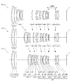
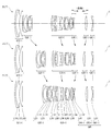
- FIG. 6 is a diagram showing a movement of a lens when the variable power optical system according to Example 1 changes from a wide-angle end state to a telephoto end state.
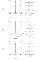
- 2A, 2B, and 2C are aberration diagrams of the variable power optical system according to Example 1 in the wide-angle end state, intermediate focal length state, and telephoto end state, respectively. .. It is a figure which shows the movement of the lens when the variable power optical system which concerns on 2nd Example changes from a wide-angle end state to a telephoto end state.
- FIG. 4A, FIG. 4B, and FIG. 4C are aberration diagrams of the variable power optical system according to the second example in the wide-angle end state, intermediate focal length state, and telephoto end state, respectively. ..
- FIG. 6A, FIG. 6B, and FIG. 6C are aberration diagrams in the wide-angle end state, the intermediate focal length state, and the telephoto end state of the variable power optical system according to the third example, respectively. .. It is a figure which shows the movement of the lens when the variable power optical system which concerns on 4th Example changes from a wide-angle end state to a telephoto end state.
- 8A, 8B, and 8C are graphs showing various aberrations of the variable power optical system according to Example 4 in the wide-angle end state, intermediate focal length state, and telephoto end state, respectively.
- FIG. 10A, 10B, and 10C are graphs showing various aberrations of the variable power optical system according to Example 5 in the wide-angle end state, the intermediate focal length state, and the telephoto end state, respectively. .. It is a figure which shows the movement of the lens at the time of the variable power optical system which concerns on 6th Example changes from a wide-angle end state to a telephoto end state.
- 12A, 12B, and 12C are aberration diagrams of the variable power optical system according to Example 6 in the wide-angle end state, intermediate focal length state, and telephoto end state, respectively. .. It is a figure which shows the movement of a lens when the variable power optical system which concerns on 7th Example changes from a wide-angle end state to a telephoto end state.
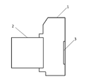
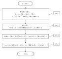
- 14A, 14B, and 14C are aberration diagrams of the variable power optical system according to the seventh example in the wide-angle end state, intermediate focal length state, and telephoto end state, respectively. .. It is a figure which shows the structure of the camera provided with the variable power optical system which concerns on this embodiment. 6 is a flowchart showing a method for manufacturing a variable power optical system according to the present embodiment.
- the camera 1 is a digital camera having a variable power optical system according to this embodiment as a taking lens 2.
- the taking lens 2 In the camera 1, light from an object (subject) (not shown) is condensed by the taking lens 2 and reaches the image sensor 3. Accordingly, the light from the subject is captured by the image sensor 3 and recorded as a subject image in a memory (not shown). In this way, the photographer can photograph the subject with the camera 1.
- the camera may be a mirrorless camera or a single-lens reflex type camera having a quick return mirror.
- variable power optical system ZL (1) as an example of the variable power optical system (zoom lens) ZL according to the present embodiment has a positive refractive power arranged in order from the object side. It has a lens group G1, a second lens group G2 having a negative refractive power, a third lens group G3 having a positive refractive power, and a subsequent lens group GR. At the time of zooming, the distance between adjacent lens groups changes.
- the first lens group G1 is fixed with respect to the image plane during zooming.
- the subsequent lens group GR includes a first focusing lens group having a negative refracting power that moves when focusing and a second focusing lens group that has a positive refracting power that moves when focusing, which are arranged in order from the object side. And a focusing lens group.
- variable power optical system ZL satisfies the following conditional expression (1).
- fF1 focal length of the first focusing lens group
- fF2 focal length of the second focusing lens group
- variable power optical system ZL may be the variable power optical system ZL (2) shown in FIG. 3, the variable power optical system ZL (3) shown in FIG. 5, or the variable power optical system shown in FIG. It may be ZL (4).
- the variable power optical system ZL according to the present embodiment may be the variable power optical system ZL (5) shown in FIG. 9, the variable power optical system ZL (6) shown in FIG. 11, or the variable power shown in FIG.
- the optical system ZL (7) may be used.
- Conditional expression (1) defines the ratio between the focal length of the first focusing lens unit and the focal length of the second focusing lens unit.
- the refracting power of the second focusing lens unit becomes strong, so that it becomes difficult to suppress fluctuations of various aberrations such as spherical aberration during focusing. Become.
- the upper limit of conditional expression (1) is set to 4.50, 4.25, 4.00, 3.75, 3.50, 3.25, 3. It may be set to 0.00, 2.75, 2.50, 2.25, or even 2.00.
- the lower limit of conditional expression (1) is set to 0.85, the effect of this embodiment can be made more reliable.
- the lower limit of conditional expression (1) is set to 0.90, 1.00, 1.10, 1.20, 1.25, 1.28, and It may be set to 1.30.
- variable power optical system ZL satisfies the following conditional expression (2).
- mTF1 the amount of movement of the first focusing lens unit when focusing from an object at infinity to a near object in the telephoto end state (the sign of the amount of movement to the object side is +, and the amount of movement to the image side is The sign is-)
- mTF2 The amount of movement of the second focusing lens group when focusing from an infinitely distant object to a short-distance object in the telephoto end state (the sign of the amount of movement to the object side is +, and the sign of the amount of movement to the image side is -And)
- Conditional expression (2) is the amount of movement of the first focusing lens unit when focusing from an infinity object to a short-distance object (object at the shortest distance) in the telephoto end state, and from the infinity object in the telephoto end state. It defines the ratio to the amount of movement of the second focusing lens unit when focusing on a short-distance object (the closest object).
- conditional expression (2) When the corresponding value of the conditional expression (2) exceeds the upper limit value, the movement amount of the second focusing lens unit becomes large, so that it becomes difficult to suppress variations in various aberrations such as spherical aberration during focusing. Become.
- the upper limit of conditional expression (2) By setting the upper limit of conditional expression (2) to -0.15, the effect of the present embodiment can be made more reliable.
- the upper limits of conditional expression (2) are set to ⁇ 0.18, ⁇ 0.20, ⁇ 0.23, ⁇ 0.25, ⁇ 0.28, It may be set to -0.30, -0.33, -0.35, -0.38, -0.40, or -0.43.
- the corresponding value of the conditional expression (2) When the corresponding value of the conditional expression (2) is less than the lower limit value, the movement amount of the first focusing lens unit becomes large, so that it becomes difficult to suppress variation of various aberrations such as spherical aberration during focusing. Become.
- the lower limit of conditional expression (2) By setting the lower limit of conditional expression (2) to -1.90, the effect of the present embodiment can be made more reliable. In order to further secure the effect of this embodiment, even if the lower limit value of the conditional expression (2) is set to -1.80, -1.70, -1.60, and further -1.50. Good.
- variable power optical system ZL satisfies the following conditional expression (3).
- ⁇ TF1 Lateral magnification of the first focusing lens group when focusing on an object at infinity in the telephoto end state
- ⁇ TF2 Lateral magnification of the second focusing lens group when focusing on an object at infinity at the telephoto end state
- Conditional expression (3) is the lateral magnification of the first focusing lens group when focusing on an object at infinity in the telephoto end state, and the second focusing lens group when focusing on an object at infinity at the telephoto end state. It defines the ratio to the lateral magnification of.
- the lateral magnification of the first focusing lens unit becomes large, so that it becomes difficult to suppress variations in various aberrations such as spherical aberration during focusing. Become.
- the upper limit of conditional expression (3) is set to 0.90, 0.85, 0.80, 0.75, 0.70, 0.65, and It may be set to 0.64.
- the lateral magnification of the second focusing lens unit becomes large, so that it becomes difficult to suppress variations in various aberrations such as spherical aberration during focusing. Become.
- the lower limit of conditional expression (3) is set to 0.15, 0.18, 0.20, 0.22, 0.24, and 0.25. You may set it.
- variable power optical system ZL it is desirable that the first focusing lens unit moves to the image side when focusing from an object at infinity to a near object. This is preferable because fluctuations in spherical aberration and field curvature can be reduced when focusing from an infinitely distant object to a near object.
- variable power optical system ZL it is desirable that the second focusing lens group moves to the object side when focusing from an object at infinity to a near object. This is preferable because fluctuations in spherical aberration and field curvature can be reduced when focusing from an infinitely distant object to a near object.
- variable power optical system ZL According to the present embodiment satisfy the following conditional expression (4). -10.00 ⁇ ( ⁇ TF1 / ⁇ WF1) ⁇ ( ⁇ TF2 / ⁇ WF2) ⁇ 10.00 (4)
- ⁇ TF1 Lateral magnification of the first focusing lens group when focusing on an object at infinity in the telephoto end state
- ⁇ WF1 Lateral magnification of the first focusing lens group when focusing on an object at infinity at the wide-angle end state
- ⁇ TF2 Lateral magnification of the second focusing lens group when focusing on an infinite object in the telephoto end state
- ⁇ WF2 Lateral magnification of the second focusing lens group when focusing on an infinite object in the wide-angle end state
- Conditional expression (4) defines the contribution of the first focusing lens unit and the second focusing lens to the zooming. By satisfying conditional expression (4), it is possible to downsize the lens barrel and satisfactorily correct various aberrations such as field curvature and spherical aberration.
- the corresponding value of the conditional expression (4) is within the above range because fluctuations of spherical aberration and curvature of field at the time of zooming can be suppressed small.
- the upper limit of conditional expression (4) is set to 6.00, 5.00, 4.00, 3.50, 3.00, 2.50, 2. It may be set to 0.00, 1.80, 1.50, or 1.30. Further, by setting the lower limit of conditional expression (4) to ⁇ 8.00, the effect of the present embodiment can be made more reliable.
- the lower limit of conditional expression (4) is set to ⁇ 6.00, ⁇ 5.00, ⁇ 4.00, ⁇ 2.50, ⁇ 1.00, It may be set to -0.50, 0.50, 0.75, or 0.90.
- variable power optical system ZL satisfies the following conditional expression (5).
- Conditional expression (5) defines the ratio between the focal length of the first lens group G1 and the focal length of the second lens group G2.
- conditional expression (5) If the corresponding value of conditional expression (5) exceeds the upper limit value, the refracting power of the second lens group G2 becomes strong, and it becomes difficult to correct coma aberration and spherical aberration.
- the upper limit of conditional expression (5) is set to 4.50, 4.30, 4.00, 3.90, 3.80, and 3.75. You may set it.
- conditional expression (5) When the corresponding value of the conditional expression (5) is below the lower limit value, the refracting power of the first lens group G1 becomes strong, and it becomes difficult to correct coma aberration and spherical aberration.
- the lower limit values of conditional expression (5) are set to 1.90, 2.00, 2.25, 2.40, 2.50, 2.70, and 2. It may be set to 0.80, 2.90, or 3.00.
- variable power optical system ZL satisfies the following conditional expression (6).
- Conditional expression (6) defines the ratio between the focal length of the first lens group G1 and the focal length of the third lens group G3.
- the upper limit values of the conditional expression (6) are set to 2.40, 2.20, 2.00, 1.90, 1.80, 1.70, 1. .60, and may be set to 1.50.
- conditional expression (6) If the corresponding value of the conditional expression (6) is less than the lower limit value, the refractive power of the first lens group G1 becomes strong, and it becomes difficult to correct spherical aberration and coma.
- the lower limit values of conditional expression (6) are set to 0.85, 0.87, 0.90, 0.92, 0.95, 0.98, and It may be set to 1.00.
- variable power optical system ZL it is desirable that the subsequent lens group GR has a fourth lens group G4 and that the following conditional expression (7) is satisfied.
- f1 focal length of the first lens group G1
- f4 focal length of the fourth lens group G4
- Conditional expression (7) defines the ratio between the focal length of the first lens group G1 and the focal length of the fourth lens group G4.
- the refracting power of the fourth lens group G4 becomes strong, and it becomes difficult to correct spherical aberration and coma.
- the upper limit values of the conditional expression (7) are set to 3.60, 3.50, 3.20, 3.00, 2.80, 2.60, 2 It may be set to 0.50, 2.40, or 2.30.
- the lower limit of conditional expression (7) is set to 0.50, 0.80, 1.00, 1.20, 1.40, 1.50, and It may be set to 1.55.
- variable power optical system ZL it is desirable that the third lens group G3 moves to the image side during zooming from the wide-angle end state to the telephoto end state. This makes it possible to satisfactorily correct various aberrations such as spherical aberration, and secure a zoom ratio that satisfies the present embodiment.
- the second lens group G2 has a positive lens that satisfies the following conditional expressions (8) to (10).
- ⁇ dP Abbe number based on the d line of the positive lens
- ndP Refractive index of the positive lens with respect to the d line
- ⁇ gFP Partial dispersion ratio of the positive lens
- the refractive index with respect to the g line of the positive lens is ngP
- nFP is the refractive index for the F line
- nCP is the refractive index for the C line of the positive lens
- ⁇ gFP (ngP-nFP) / (nFP-nCP)
- conditional expression (8) defines an appropriate range of the Abbe's number based on the d-line of the positive lens in the second lens group G2.
- conditional expression (8) If the corresponding value of conditional expression (8) exceeds the upper limit value, it becomes difficult to correct the axial chromatic aberration, which is not preferable.
- the upper limit of conditional expression (8) By setting the upper limit of conditional expression (8) to 32.5, the effect of this embodiment can be made more reliable. In order to further secure the effect of this embodiment, it is preferable to set the upper limit of conditional expression (8) to 31.5.
- conditional expression (8) If the corresponding value of conditional expression (8) is below the lower limit value, it becomes difficult to correct the axial chromatic aberration, which is not preferable.
- the lower limit of conditional expression (8) is set to 22.00, 23.00, 23.50, 24.00, 25.00, and further 26.00. Preferably.
- conditional expression (9) defines an appropriate relationship between the refractive index of the positive lens in the second lens group G2 with respect to the d-line and the Abbe number based on the d-line.
- conditional expression (9) If the corresponding value of the conditional expression (9) deviates from the above range, it becomes difficult to correct the curvature of field, for example, the Petzval sum becomes small, which is not preferable.
- the upper limit of conditional expression (9) By setting the upper limit of conditional expression (9) to 2.10, the effect of this embodiment can be made more reliable. In order to further secure the effect of this embodiment, it is preferable to set the upper limit value of the conditional expression (9) to 2.08, further 2.06.
- the lower limit of conditional expression (9) to 1.84 the effect of the present embodiment can be made more reliable. In order to further secure the effect of this embodiment, it is preferable to set the lower limit of conditional expression (9) to 1.85.
- conditional expression (10) appropriately defines the anomalous dispersion of the positive lens in the second lens group G2.
- conditional expression (10) it is possible to satisfactorily correct the secondary spectrum in addition to the primary achromatization in the correction of chromatic aberration.
- conditional expression (10) If the corresponding value of conditional expression (10) is less than the lower limit value, the anomalous dispersion of the positive lens becomes small, and it becomes difficult to correct chromatic aberration.
- the lower limit of conditional expression (10) By setting the lower limit of conditional expression (10) to 0.704, the effect of this embodiment can be made more reliable. In order to further secure the effect of this embodiment, it is preferable to set the lower limit values of conditional expression (10) to 0.708, 0.710, and 0.715.
- variable power optical system ZL preferably satisfies the following conditional expression (11).
- Conditional expression (11) defines the total angle of view of the variable power optical system ZL in the wide-angle end state. By satisfying the conditional expression (11), it is possible to satisfactorily correct various aberrations such as coma, distortion, and field curvature while having a wide angle of view that satisfies the present embodiment.
- the lower limit of conditional expression (11) By setting the lower limit of conditional expression (11) to 27.00 °, the effect of the present embodiment can be made more reliable. In order to further secure the effect of this embodiment, even if the lower limit value of the conditional expression (11) is set to 29.00 °, 30.00 °, 32.00 °, and 33.00 °. Good.
- the upper limit of conditional expression (11) is set to 45.00 °, 42.00 °, 40.00 °, 38.00 °, 36.00 °, Further, it may be set to 35.00 °.
- variable power optical system ZL satisfies the following conditional expression (12).
- Conditional expression (12) defines the total angle of view of the variable magnification optical system ZL in the telephoto end state.
- it is possible to excellently correct various aberrations such as coma, distortion, and field curvature.
- the upper limit of conditional expression (12) By setting the upper limit of conditional expression (12) to 18.00 °, the effect of the present embodiment can be made more reliable.
- the lower limit of conditional expression (12) is set to 8.00 °, 10.00 °, 11.00 °, and further 12.00 °. Good.
- variable power optical system ZL satisfies the following conditional expression (13).
- BFw Back focus of the variable power optical system ZL in the wide-angle end state
- fw Focal length of the variable power optical system ZL in the wide-angle end state
- Conditional expression (13) defines the ratio of the back focus of the variable power optical system ZL in the wide-angle end state to the focal length of the variable power optical system ZL in the wide-angle end state.
- conditional expression (13) When the corresponding value of the conditional expression (13) exceeds the upper limit value, the back focus becomes too large with respect to the focal length of the variable power optical system ZL in the wide-angle end state, so that various aberrations including coma aberration in the wide-angle end state. Is difficult to correct.
- the upper limit of conditional expression (13) By setting the upper limit of conditional expression (13) to 0.80, the effect of the present embodiment can be made more reliable. In order to further secure the effect of the present embodiment, even if the upper limit of conditional expression (13) is set to 0.75, 0.70, 0.65, 0.60, and even 0.55. Good.
- the corresponding value of the conditional expression (13) is less than the lower limit value, the back focus becomes too small with respect to the focal length of the variable power optical system ZL in the wide-angle end state, so that various aberrations including coma aberration in the wide-angle end state. Is difficult to correct. Further, it becomes difficult to arrange the mechanical member of the lens barrel.
- the lower limit value of the conditional expression (13) may be set to 0.30, 0.35, 0.40, and 0.42.
- the manufacturing method of the variable power optical system ZL according to the present embodiment will be outlined with reference to FIG.
- the configuration is such that the distance between adjacent lens groups changes during zooming (step ST2).
- the first lens group G1 is fixed with respect to the image plane.
- the third lens group G3 moves toward the image side along the optical axis.
- the subsequent lens group GR has, in order from the object side, a first focusing lens group having a negative refractive power that moves during focusing, and a second focusing lens group that has a positive refractive power that moves during focusing.
- the focusing lens group is arranged (step ST3).
- each lens is arranged in the lens barrel so as to satisfy at least the conditional expression (1) (step ST4). According to such a manufacturing method, it becomes possible to manufacture a variable power optical system in which various aberrations such as spherical aberration are properly corrected.
- variable-magnification optical systems ZL ⁇ ZL (1) to ZL (7) ⁇ are at the wide-angle end. It is a figure which shows the movement of the lens at the time of changing from a state to a telephoto end state.
- the moving direction along the optical axis of the lens group that moves during zooming from the wide-angle end state to the telephoto end state is indicated by an arrow.
- the moving direction when the focusing lens group focuses on an object at a short distance from infinity is indicated by an arrow together with the character "focus".
- each lens group is represented by a combination of reference numeral G and a numeral
- each lens is represented by a combination of reference numeral L and a numeral.
- the lens groups and the like are represented independently by using combinations of symbols and numbers for each embodiment. Therefore, even if the same combination of reference numerals and numbers is used between the embodiments, it does not mean that they have the same configuration.
- Tables 1 to 7 are shown below. Of these, Table 1 is the first example, Table 2 is the second example, Table 3 is the third example, Table 4 is the fourth example, and Table 5 is the fifth example. 5th Example, Table 6 is a table showing respective specification data in the 6th Example, and Table 7 is in the 7th Example.
- FNO is the F number
- 2 ⁇ is the angle of view (unit is ° (degrees)
- ⁇ is the half angle of view
- Y is the image height
- TL is the distance from the lens front surface to the final lens surface on the optical axis when focused on infinity
- BF is the image from the final lens surface on the optical axis when focused on infinity.
- the air equivalent distance (back focus) to the surface I is shown. Note that these values are shown for each of the wide-angle end (W), the intermediate focal length (M), and the telephoto end (T) in each variable power state.
- ⁇ gFP represents the partial dispersion ratio of the positive lens in the second lens group.
- mTF1 indicates the amount of movement of the first focusing lens unit when focusing from an infinitely distant object to a short-distance object (object at the closest distance) in the telephoto end state (the sign of the amount of movement to the object side is + , And the sign of the amount of movement to the image side is-).
- mTF2 indicates the amount of movement of the second focusing lens unit when focusing from an infinitely distant object to a short-distance object (shortest-distance object) in the telephoto end state.
- ⁇ TF1 represents the lateral magnification of the first focusing lens unit when focusing on an object at infinity in the telephoto end state.
- ⁇ TF2 represents the lateral magnification of the second focusing lens unit when focusing on an object at infinity in the telephoto end state.
- ⁇ WF1 represents the lateral magnification of the first focusing lens unit when focusing on an object at infinity in the wide-angle end state.
- ⁇ WF2 represents the lateral magnification of the second focusing lens unit when focusing on an object at infinity in the wide-angle end state.
- the surface number indicates the order of the optical surface from the object side along the traveling direction of the light ray, and R represents the radius of curvature of each optical surface (the surface whose center of curvature is located on the image side).
- D is a surface distance that is a distance on the optical axis from each optical surface to the next optical surface (or image surface)
- nd is a refractive index of the material of the optical member with respect to d-line
- ⁇ d is an optical value.
- the Abbe number of the material of the member based on the d-line and ⁇ gF indicate the partial dispersion ratio of the material of the optical member.
- the radius of curvature " ⁇ " indicates a plane or an aperture, and (stop S) indicates an aperture stop.
- the description of the refractive index of air nd 1.0000 is omitted.
- the surface number is marked with * and the radius of curvature R column indicates the paraxial radius of curvature.
- the C of the material of the optical member is C
- the partial dispersion ratio ⁇ gF of the material of the optical member is defined by the following expression (A).
- the [Lens group data] table shows the starting surface (the surface closest to the object) and the focal length of each lens group.
- the table of [Variable spacing data] shows the surface spacing at the surface numbers for which the surface spacing is "variable” in the table showing [Lens specifications].
- W wide-angle end
- M intermediate focal length
- T telephoto end
- f focal length of the entire lens system
- ⁇ indicates the photographing magnification.
- the table of [Values corresponding to conditional expressions] shows the values corresponding to each conditional expression.
- the focal length f, radius of curvature R, surface distance D, and other lengths listed are generally “mm” unless otherwise specified, but the optical system is proportionally enlarged. Alternatively, since the same optical performance can be obtained even if the proportion is reduced, the invention is not limited to this.
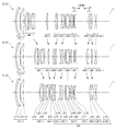
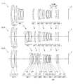
- FIG. 1 is a diagram showing the movement of the lens when the variable power optical system according to Example 1 changes from the wide-angle end state to the telephoto end state.
- the variable power optical system ZL (1) according to the first example includes a first lens group G1 having a positive refractive power, a second lens group G2 having a negative refractive power, arranged in order from the object side, and a positive lens group G2.
- the second lens group G2, the third lens group G3, the fifth lens group G5, the seventh lens group G7, and the eighth lens group G8 are separately provided in FIG. Moves in the direction indicated by the arrow, and the distance between adjacent lens groups changes.
- the first lens group G1, the fourth lens group G4, the sixth lens group G6, and the ninth lens group G9 are fixed with respect to the image plane I.
- the fourth lens group G4, the fifth lens group G5, the sixth lens group G6, the seventh lens group G7, the eighth lens group G8, and the ninth lens group G9 are subsequent lens groups. It corresponds to GR.
- the symbol (+) or ( ⁇ ) attached to each lens group symbol indicates the refractive power of each lens group, and this is the same in all the examples below.
- the first lens group G1 includes, in order from the object side, a cemented lens of a negative meniscus lens L11 having a convex surface facing the object side and a plano-convex positive lens L12 having a convex surface facing the object side, and a convex surface facing the object side. And a positive meniscus lens L13 facing the lens.
- the second lens group G2 includes, in order from the object side, a negative meniscus lens L21 having a convex surface facing the object side, a biconcave negative lens L22, a positive meniscus lens L23 having a convex surface facing the object side, and It is composed of a concave negative lens L24.
- the third lens group G3 is composed of a positive meniscus lens L31 having a convex surface directed toward the object side.
- the fourth lens group G4 is composed of a biconvex positive lens L41 and a negative meniscus lens L42 having a convex surface directed toward the object side, which are arranged in order from the object side.
- the fifth lens group G5 is composed of a cemented lens made up of a biconcave negative lens L51 and a biconvex positive lens L52.
- An aperture stop S is disposed on the most object side of the fifth lens group G5, and moves with the fifth lens group G5 during zooming.
- the sixth lens group G6 is a cemented lens of a negative meniscus lens L61 having a convex surface directed toward the object side, a biconvex positive lens L62, and a negative meniscus lens L63 having a concave surface directed toward the object side, which are arranged in order from the object side. And a positive meniscus lens L64 having a convex surface facing the object side.
- the positive lens L62 has an aspherical lens surface on the object side.
- the seventh lens group G7 is composed of, in order from the object side, a positive meniscus lens L71 having a concave surface facing the object side and a negative meniscus lens L72 having a convex surface facing the object side.
- the eighth lens group G8 is composed of a biconvex positive lens L81.
- the ninth lens group G9 is composed of, in order from the object side, a negative meniscus lens L91 having a concave surface facing the object side and a negative meniscus lens L92 having a concave surface facing the object side.
- the negative meniscus lens L91 has an aspherical lens surface on the object side.
- the image plane I is disposed on the image side of the ninth lens group G9. That is, the ninth lens group G9 corresponds to the final lens group.
- the seventh lens group G7 is moved to the image plane I side and the eighth lens group G8 is moved to the object side, thereby changing from a long-distance object to a short-distance object (from an infinite object to a finite object). Is focused. That is, the seventh lens group G7 corresponds to the first focusing lens group, and the eighth lens group G8 corresponds to the second focusing lens group.
- Table 1 below lists values of specifications of the variable power optical system according to the first example.
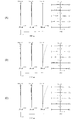
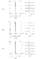
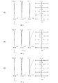
- 2A, 2B, and 2C are aberration diagrams of the variable power optical system according to Example 1 in the wide-angle end state, intermediate focal length state, and telephoto end state, respectively. ..
- FNO indicates the F number
- Y indicates the image height.
- the spherical aberration diagram shows the F number value corresponding to the maximum aperture
- the astigmatism diagram and the distortion diagram show the maximum image height
- the lateral aberration diagram shows the image height value.
- the solid line shows the sagittal image plane
- the broken line shows the meridional image plane.
- variable magnification optical system according to Example 1 has excellent aberration performance and excellent imaging performance.
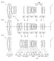
- FIG. 3 is a diagram showing the movement of the lens when the variable power optical system according to the second example changes from the wide-angle end state to the telephoto end state.
- the variable power optical system ZL (2) according to the second example includes a first lens group G1 having a positive refractive power, a second lens group G2 having a negative refractive power, arranged in order from the object side, and a positive lens group G2.
- a seventh lens group G7 having negative refractive power At the time of zooming from the wide-angle end state to the telephoto end state, the second lens group G2, the third lens group G3, the fifth lens group G5, and the sixth lens group G6 are individually moved in the directions shown by arrows in FIG. By moving, the distance between the adjacent lens groups changes.
- the first lens group G1, the fourth lens group G4, and the seventh lens group G7 are fixed with respect to the image plane I.
- the lens group including the fourth lens group G4, the fifth lens group G5, the sixth lens group G6, and the seventh lens group G7 corresponds to the subsequent lens group GR.
- the first lens group G1 includes, in order from the object side, a cemented lens of a negative meniscus lens L11 having a convex surface facing the object side and a biconvex positive lens L12, and a positive meniscus lens L13 having a convex surface facing the object side. Composed of and.
- the second lens group G2 includes, in order from the object side, a negative meniscus lens L21 having a convex surface directed toward the object side, a biconcave negative lens L22, a positive meniscus lens L23 having a convex surface directed toward the object side, and an object. And a negative meniscus lens L24 having a concave surface directed to the side.
- the third lens group G3 is composed of a positive meniscus lens L31 having a convex surface directed toward the object side.
- the fourth lens group G4 includes, in order from the object side, a positive meniscus lens L41 having a convex surface directed toward the object side, a positive meniscus lens L42 having a convex surface directed toward the object side, a biconcave negative lens L43, and a biconvex lens.
- An aperture stop S is arranged between the positive meniscus lens L42 and the negative lens L43 in the fourth lens group G4, and moves with the fourth lens group G4 during zooming.
- the lens surface of the positive lens L46 on the object side is an aspherical surface.
- the fifth lens group G5 is composed of a positive meniscus lens L51 having a concave surface facing the object side and a biconcave negative lens L52 arranged in order from the object side.
- the sixth lens group G6 is composed of a biconvex positive lens L61.
- the seventh lens group G7 is composed of a biconcave negative lens L71.
- the negative lens L71 has an aspherical lens surface on the object side.
- the image plane I is disposed on the image side of the seventh lens group G7. That is, the seventh lens group G7 corresponds to the final lens group.
- the fifth lens group G5 is moved to the image plane I side, and the sixth lens group G6 is moved to the object side, thereby changing from a long-distance object to a short-distance object (from an infinite object to a finite object). Is focused. That is, the fifth lens group G5 corresponds to the first focusing lens group, and the sixth lens group G6 corresponds to the second focusing lens group.
- Table 2 below lists values of specifications of the variable power optical system according to the second example.
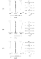
- FIG. 4A, FIG. 4B, and FIG. 4C are aberration diagrams of the variable power optical system according to the second example in the wide-angle end state, intermediate focal length state, and telephoto end state, respectively. .. It is understood from the various aberration diagrams that the variable power optical system according to Example 2 has the various aberrations well corrected and has excellent imaging performance.
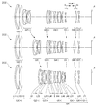
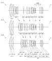
- FIG. 5 is a diagram showing the movement of the lens when the variable power optical system according to the third example changes from the wide-angle end state to the telephoto end state.
- the variable power optical system ZL (3) according to the third example includes a first lens group G1 having a positive refractive power, a second lens group G2 having a negative refractive power, arranged in order from the object side, and a positive lens group G2.
- the first lens group G1, the sixth lens group G6, and the tenth lens group G10 are fixed with respect to the image plane I.
- the lens group corresponds to the subsequent lens group GR.
- the first lens group G1 includes, in order from the object side, a cemented lens of a negative meniscus lens L11 having a convex surface facing the object side and a biconvex positive lens L12, and a positive meniscus lens L13 having a convex surface facing the object side. Composed of and.
- the second lens group G2 includes, in order from the object side, a negative meniscus lens L21 having a convex surface facing the object side, a biconcave negative lens L22, a positive meniscus lens L23 having a convex surface facing the object side, and It is composed of a concave negative lens L24.
- the third lens group G3 is composed of a positive meniscus lens L31 having a convex surface directed toward the object side.
- the fourth lens group G4 includes a biconvex positive lens L41 and a positive meniscus lens L42 having a convex surface facing the object side, which are arranged in order from the object side.
- the fifth lens group G5 is composed of a cemented lens made up of a biconcave negative lens L51 and a biconvex positive lens L52.
- An aperture stop S is disposed on the most object side of the fifth lens group G5, and moves with the fifth lens group G5 during zooming.
- the sixth lens group G6 is a cemented lens of a negative meniscus lens L61 having a convex surface directed toward the object side, a biconvex positive lens L62, and a negative meniscus lens L63 having a concave surface directed toward the object side, which are arranged in order from the object side. And a positive meniscus lens L64 having a convex surface facing the object side.
- the positive lens L62 has an aspherical lens surface on the object side.
- the seventh lens group G7 is composed of, in order from the object side, a biconvex positive lens L71 and a negative meniscus lens L72 having a convex surface directed toward the object side.
- the eighth lens group G8 is composed of a positive meniscus lens L81 having a convex surface directed toward the object side.
- the ninth lens group G9 is composed of a positive meniscus lens L91 having a concave surface facing the object side.
- the positive meniscus lens L91 has an aspherical lens surface on the object side.
- the tenth lens group G10 is composed of a biconcave negative lens L101.
- the image plane I is disposed on the image side of the tenth lens group G10. That is, the tenth lens group G10 corresponds to the final lens group.
- the seventh lens group G7 is moved to the image plane I side and the eighth lens group G8 is moved to the object side, thereby changing from a long-distance object to a short-distance object (from an infinite object to a finite object). Is focused. That is, the seventh lens group G7 corresponds to the first focusing lens group, and the eighth lens group G8 corresponds to the second focusing lens group.
- Table 3 below shows the values of specifications of the variable power optical system according to the third example.
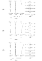
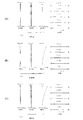
- FIG. 6A, FIG. 6A, and FIG. 6C are aberration diagrams in the wide-angle end state, the intermediate focal length state, and the telephoto end state of the variable power optical system according to the third example, respectively. .. It is understood from the various aberration diagrams that the variable power optical system according to Example 3 has the various aberrations well corrected and has excellent imaging performance.
- FIG. 7 is a diagram showing the movement of the lens when the variable power optical system according to the fourth example changes from the wide-angle end state to the telephoto end state.
- the variable power optical system ZL (4) according to the fourth example includes a first lens group G1 having a positive refractive power, a second lens group G2 having a negative refractive power, arranged in order from the object side, and a positive lens group G2.
- a seventh lens group G7 having a positive refractive power and an eighth lens group G8 having a negative refractive power are separately provided in FIG. Moves in the direction indicated by the arrow, and the distance between adjacent lens groups changes. It should be noted that during zooming, the first lens group G1, the fifth lens group G5, and the eighth lens group G8 are fixed with respect to the image plane I.
- the lens group including the fourth lens group G4, the fifth lens group G5, the sixth lens group G6, the seventh lens group G7, and the eighth lens group G8 corresponds to the subsequent lens group GR.
- the first lens group G1 includes, in order from the object side, a cemented lens of a negative meniscus lens L11 having a convex surface facing the object side and a biconvex positive lens L12, and a positive meniscus lens L13 having a convex surface facing the object side. Composed of and.
- the second lens group G2 includes, in order from the object side, a negative meniscus lens L21 having a convex surface facing the object side, a biconcave negative lens L22, a positive meniscus lens L23 having a convex surface facing the object side, and It is composed of a concave negative lens L24.
- the third lens group G3 is composed of a positive meniscus lens L31 having a convex surface directed toward the object side.
- the fourth lens group G4 includes a biconvex positive lens L41 and a positive meniscus lens L42 having a convex surface facing the object side, which are arranged in order from the object side.
- the fifth lens group G5 includes, in order from the object side, a cemented lens of a biconcave negative lens L51 and a biconvex positive lens L52, a negative meniscus lens L53 having a convex surface directed toward the object side, and a biconvex lens. It is composed of a cemented lens of a positive lens L54 having a shape and a negative meniscus lens L55 having a concave surface facing the object side, and a positive meniscus lens L56 having a convex surface facing the object side.
- An aperture stop S is disposed on the most object side of the fifth lens group G5, and is fixed to the image plane I together with the fifth lens group G5 during zooming.
- the positive lens L54 has an aspherical lens surface on the object side.
- the sixth lens group G6 is composed of, in order from the object side, a positive meniscus lens L61 having a concave surface facing the object side and a negative meniscus lens L62 having a convex surface facing the object side.
- the seventh lens group G7 is composed of a biconvex positive lens L71.
- the eighth lens group G8 is composed of, in order from the object side, a negative meniscus lens L81 having a convex surface facing the object side and a negative meniscus lens L82 having a concave surface facing the object side.
- the negative meniscus lens L81 has an aspherical lens surface on the object side.
- the image plane I is disposed on the image side of the eighth lens group G8. That is, the eighth lens group G8 corresponds to the final lens group.
- the sixth lens group G6 is moved to the image plane I side and the seventh lens group G7 is moved to the object side, thereby changing from a long-distance object to a short-distance object (from an infinite object to a finite object). Is focused. That is, the sixth lens group G6 corresponds to the first focusing lens group, and the seventh lens group G7 corresponds to the second focusing lens group.
- Table 4 below shows values of specifications of the variable power optical system according to the fourth example.
- FIG. 8A, 8B, and 8C are graphs showing various aberrations of the variable power optical system according to Example 4 in the wide-angle end state, intermediate focal length state, and telephoto end state, respectively. .. It is understood from the various aberration diagrams that the variable power optical system according to Example 4 has the various aberrations well corrected and has excellent imaging performance.
- FIG. 9 is a diagram showing the movement of the lens when the variable power optical system according to the fifth example changes from the wide-angle end state to the telephoto end state.
- the variable power optical system ZL (5) according to the fifth example includes a first lens group G1 having a positive refractive power, a second lens group G2 having a negative refractive power, and a positive lens group arranged in order from the object side.
- the second lens group G2, the third lens group G3, the fifth lens group G5, the seventh lens group G7, and the eighth lens group G8 are separately provided in FIG. Moves in the direction indicated by the arrow, and the distance between adjacent lens groups changes.
- the first lens group G1, the fourth lens group G4, the sixth lens group G6, and the ninth lens group G9 are fixed with respect to the image plane I.
- the fourth lens group G4, the fifth lens group G5, the sixth lens group G6, the seventh lens group G7, the eighth lens group G8, and the ninth lens group G9 are subsequent lens groups. It corresponds to GR.
- the first lens group G1 includes, in order from the object side, a cemented lens of a negative meniscus lens L11 having a convex surface facing the object side and a biconvex positive lens L12, and a positive meniscus lens L13 having a convex surface facing the object side. Composed of and.
- the second lens group G2 includes, in order from the object side, a negative meniscus lens L21 having a convex surface directed toward the object side, a biconvex positive lens L22, a biconcave negative lens L23, and a concave surface directed toward the object side. And a negative meniscus lens L24 facing the lens.
- the third lens group G3 is composed of a positive meniscus lens L31 having a convex surface directed toward the object side.
- the fourth lens group G4 is composed of a positive meniscus lens L41 having a convex surface directed toward the object side and a biconvex positive lens L42 arranged in order from the object side.
- the fifth lens group G5 is composed of a cemented lens of a biconcave negative lens L51 and a positive meniscus lens L52 having a convex surface facing the object side.
- An aperture stop S is disposed on the most object side of the fifth lens group G5, and moves with the fifth lens group G5 during zooming.
- the sixth lens group G6 includes, in order from the object side, a negative meniscus lens L61 having a convex surface directed toward the object side, a biconvex positive lens L62, and a positive meniscus lens L63 having a convex surface directed toward the object side. To be done.
- the image-side lens surface of the positive lens L62 is an aspherical surface.
- the seventh lens group G7 is composed of a positive meniscus lens L71 with a concave surface facing the object side and a biconcave negative lens L72, which are arranged in order from the object side.
- the eighth lens group G8 is composed of a biconvex positive lens L81.
- the ninth lens group G9 is composed of a biconcave negative lens L91.
- the image plane I is disposed on the image side of the ninth lens group G9. That is, the ninth lens group G9 corresponds to the final lens group.
- the seventh lens group G7 is moved to the image plane I side and the eighth lens group G8 is moved to the object side, thereby changing from a long-distance object to a short-distance object (from an infinite object to a finite object). Is focused. That is, the seventh lens group G7 corresponds to the first focusing lens group, and the eighth lens group G8 corresponds to the second focusing lens group.
- Table 5 lists values of specifications of the variable power optical system according to the fifth example.
- 10A, 10B, and 10C are graphs showing various aberrations of the variable power optical system according to Example 5 in the wide-angle end state, the intermediate focal length state, and the telephoto end state, respectively. .. It is understood from the various aberration diagrams that the variable power optical system according to the fifth example has various aberrations favorably corrected and has excellent imaging performance.
- FIG. 11 is a diagram showing the movement of the lens when the zoom optical system according to Example 6 changes from the wide-angle end state to the telephoto end state.
- the variable power optical system ZL (6) according to Example 6 has a first lens group G1 having a positive refractive power, a second lens group G2 having a negative refractive power, and a positive lens group arranged in order from the object side.
- the second lens group G2, the third lens group G3, the fifth lens group G5, the seventh lens group G7, and the eighth lens group G8 are separately provided in FIG. Moves in the direction indicated by the arrow, and the distance between adjacent lens groups changes.
- the first lens group G1, the fourth lens group G4, the sixth lens group G6, and the ninth lens group G9 are fixed with respect to the image plane I.
- the fourth lens group G4, the fifth lens group G5, the sixth lens group G6, the seventh lens group G7, the eighth lens group G8, and the ninth lens group G9 are subsequent lens groups. It corresponds to GR.
- the first lens group G1 includes, in order from the object side, a cemented lens of a negative meniscus lens L11 having a convex surface facing the object side and a biconvex positive lens L12, and a positive meniscus lens L13 having a convex surface facing the object side. Composed of and.
- the second lens group G2 includes, in order from the object side, a negative meniscus lens L21 having a convex surface facing the object side, a biconcave negative lens L22, a positive meniscus lens L23 having a convex surface facing the object side, and It is composed of a concave negative lens L24.
- the third lens group G3 is composed of a positive meniscus lens L31 having a convex surface directed toward the object side.
- the fourth lens group G4 is composed of a biconvex positive lens L41.
- the positive lens L41 has an aspherical lens surface on the object side.
- the fifth lens group G5 is composed of a cemented lens made up of a biconcave negative lens L51 and a biconvex positive lens L52.
- An aperture stop S is disposed on the most object side of the fifth lens group G5, and moves with the fifth lens group G5 during zooming.
- the sixth lens group G6 is a cemented lens of a negative meniscus lens L61 having a convex surface directed toward the object side, a biconvex positive lens L62, and a negative meniscus lens L63 having a concave surface directed toward the object side, which are arranged in order from the object side. And a positive meniscus lens L64 having a convex surface facing the object side.
- the positive lens L62 has an aspherical lens surface on the object side.
- the seventh lens group G7 is composed of a biconvex positive lens L71 and a biconcave negative lens L72, which are arranged in order from the object side.
- the eighth lens group G8 is composed of a biconvex positive lens L81.
- the ninth lens group G9 is composed of, in order from the object side, a biconcave negative lens L91 and a negative meniscus lens L92 having a concave surface facing the object side.
- the negative lens L91 has an aspherical lens surface on the object side.
- the image plane I is disposed on the image side of the ninth lens group G9. That is, the ninth lens group G9 corresponds to the final lens group.
- the seventh lens group G7 is moved to the image plane I side and the eighth lens group G8 is moved to the object side, thereby changing from a long-distance object to a short-distance object (from an infinite object to a finite object). Is focused. That is, the seventh lens group G7 corresponds to the first focusing lens group, and the eighth lens group G8 corresponds to the second focusing lens group.
- Table 6 below lists values of specifications of the variable power optical system according to the sixth example.
- 12A, 12B, and 12C are aberration diagrams of the variable power optical system according to Example 6 in the wide-angle end state, intermediate focal length state, and telephoto end state, respectively. .. It is understood from the various aberration diagrams that the variable power optical system of the sixth example has the various aberrations corrected well and has excellent imaging performance.
- FIG. 13 is a diagram showing the movement of the lens when the zoom optical system according to Example 7 changes from the wide-angle end state to the telephoto end state.
- the variable power optical system ZL (7) according to Example 7 has a first lens group G1 having a positive refractive power, a second lens group G2 having a negative refractive power, and a positive lens group arranged in order from the object side.
- the second lens group G2, the third lens group G3, the fourth lens group G4, and the fifth lens group G5 are separately moved in the directions shown by the arrows in FIG. By moving, the distance between the adjacent lens groups changes.
- the first lens group G1 and the sixth lens group G6 are fixed with respect to the image plane I during zooming.
- the lens group including the fourth lens group G4, the fifth lens group G5, and the sixth lens group G6 corresponds to the subsequent lens group GR.
- the first lens group G1 includes, in order from the object side, a cemented lens of a negative meniscus lens L11 having a convex surface facing the object side and a biconvex positive lens L12, and a positive meniscus lens L13 having a convex surface facing the object side. Composed of and.
- the second lens group G2 includes, in order from the object side, a negative meniscus lens L21 having a convex surface directed toward the object side, a biconcave negative lens L22, a positive meniscus lens L23 having a convex surface directed toward the object side, and an object. And a negative meniscus lens L24 having a concave surface directed to the side.
- the third lens group G3 includes, in order from the object side, a positive meniscus lens L31 having a convex surface directed toward the object side, a positive meniscus lens L32 having a convex surface directed toward the object side, and a biconvex positive lens L33.
- An aperture stop S is provided between the positive lens L33 and the negative lens L34 in the third lens group G3, and moves with the third lens group G3 during zooming.
- the object-side lens surface of the positive lens L37 is an aspherical surface.
- the fourth lens group G4 is composed of a positive meniscus lens L41 having a concave surface facing the object side and a biconcave negative lens L42, which are arranged in order from the object side.
- the fifth lens group G5 is composed of a biconvex positive lens L51.
- the sixth lens group G6 is composed of a negative meniscus lens L61 having a concave surface facing the object side.
- the negative meniscus lens L61 has an aspherical lens surface on the object side.
- the image plane I is disposed on the image side of the sixth lens group G6. That is, the sixth lens group G6 corresponds to the final lens group.
- the fourth lens group G4 is moved to the image plane I side and the fifth lens group G5 is moved to the object side, thereby changing from a long-distance object to a short-distance object (from an infinite object to a finite object). Is focused. That is, the fourth lens group G4 corresponds to the first focusing lens group, and the fifth lens group G5 corresponds to the second focusing lens group.
- Table 7 below lists values of specifications of the variable power optical system according to the seventh example.
- variable power optical system 14A, 14B, and 14C are aberration diagrams of the variable power optical system according to the seventh example in the wide-angle end state, intermediate focal length state, and telephoto end state, respectively. .. It is understood from the various aberration diagrams that the variable power optical system of the seventh example has various aberrations corrected well and has excellent imaging performance.
- each embodiment it is possible to realize a variable power optical system in which various aberrations such as spherical aberration are favorably corrected.
- each of the above-mentioned embodiments shows a specific example of the present invention, and the present invention is not limited thereto.
- variable power optical system As the numerical examples of the variable power optical system, the configurations of the 6-group, 7-group, 8-group, 9-group, and 10-group configuration are shown, but the present application is not limited to this, and other group configurations (for example, 5 group and It is also possible to construct a variable power optical system of 11 groups or the like. Specifically, a configuration may be adopted in which a lens or a lens group is added to the most object side or most image plane side of the variable power optical system.
- the lens group refers to a portion having at least one lens, which is separated by an air gap that changes during zooming.
- the lens surface may be a spherical surface, a flat surface, or an aspherical surface.
- lens processing and assembly adjustment are facilitated, and deterioration of optical performance due to an error in processing and assembly adjustment can be prevented, which is preferable. Further, even if the image plane is deviated, the drawing performance is less deteriorated, which is preferable.
- the aspherical surface is an aspherical surface formed by grinding, a glass mold aspherical surface formed by molding glass into an aspherical shape, or a composite type aspherical surface formed by resin forming an aspherical surface on the glass surface. Either is fine.
- the lens surface may be a diffractive surface, and the lens may be a gradient index lens (GRIN lens) or a plastic lens.
- each lens surface may be coated with an antireflection film having a high transmittance in a wide wavelength range in order to reduce flare and ghost and achieve high contrast optical performance.
- flare and ghost can be reduced and high optical performance with high contrast can be achieved.
Abstract
L'invention concerne un système optique à grossissement variable (ZL) comprenant, disposés dans l'ordre à partir du côté objet : un premier groupe de lentilles (G1) ayant une réfringence positive : un deuxième groupe de lentilles (G2) ayant une réfringence négative : un troisième groupe de lentilles (G3) ayant une réfringence positive ; et un groupe de lentilles subséquentes (GR). Lors d'un zoom, l'intervalle entre des groupes adjacents change, et le premier groupe de lentilles (G1) est fixe par rapport au plan d'image, et lors d'un zoom de l'état d'extrémité grand angle à l'état d'extrémité téléobjectif, le troisième groupe de lentilles (G3) se déplace vers le côté image. Le groupe de lentilles subséquentes (GR) a, disposé dans l'ordre à partir du côté objet, un premier groupe de lentilles de focalisation ayant une réfringence négative qui se déplace lors de la focalisation, et un second groupe de lentilles de focalisation ayant une réfringence positive qui se déplace lors de la focalisation. Le système optique à grossissement variable (ZL) satisfait l'expression conditionnelle suivante. 0.80 < (–fF1)/fF2 < 5.00, où fF1 est la longueur focale du premier groupe de lentilles de focalisation, et fF2 est la longueur focale du second groupe de lentilles de focalisation.
Priority Applications (7)
| Application Number | Priority Date | Filing Date | Title |
|---|---|---|---|
| JP2020557053A JP7160109B2 (ja) | 2018-11-20 | 2018-11-20 | 変倍光学系および光学機器 |
| US17/283,717 US20210349293A1 (en) | 2018-11-20 | 2018-11-20 | Zoom optical system, optical device, and method for manufacturing zoom optical system |
| CN202310259645.6A CN116338916A (zh) | 2018-11-20 | 2018-11-20 | 变倍光学系统、光学设备以及变倍光学系统的制造方法 |
| CN201880098751.8A CN112867953B (zh) | 2018-11-20 | 2018-11-20 | 变倍光学系统以及光学设备 |
| PCT/JP2018/042763 WO2020105104A1 (fr) | 2018-11-20 | 2018-11-20 | Système optique à grossissement variable, dispositif optique, et procédé de production d'un système optique à grossissement variable |
| JP2022155730A JP7371742B2 (ja) | 2018-11-20 | 2022-09-29 | 変倍光学系および光学機器 |
| JP2023177956A JP2023171671A (ja) | 2018-11-20 | 2023-10-16 | 変倍光学系、光学機器および変倍光学系の製造方法 |
Applications Claiming Priority (1)
| Application Number | Priority Date | Filing Date | Title |
|---|---|---|---|
| PCT/JP2018/042763 WO2020105104A1 (fr) | 2018-11-20 | 2018-11-20 | Système optique à grossissement variable, dispositif optique, et procédé de production d'un système optique à grossissement variable |
Publications (1)
| Publication Number | Publication Date |
|---|---|
| WO2020105104A1 true WO2020105104A1 (fr) | 2020-05-28 |
Family
ID=70774668
Family Applications (1)
| Application Number | Title | Priority Date | Filing Date |
|---|---|---|---|
| PCT/JP2018/042763 WO2020105104A1 (fr) | 2018-11-20 | 2018-11-20 | Système optique à grossissement variable, dispositif optique, et procédé de production d'un système optique à grossissement variable |
Country Status (4)
| Country | Link |
|---|---|
| US (1) | US20210349293A1 (fr) |
| JP (3) | JP7160109B2 (fr) |
| CN (2) | CN112867953B (fr) |
| WO (1) | WO2020105104A1 (fr) |
Cited By (3)
| Publication number | Priority date | Publication date | Assignee | Title |
|---|---|---|---|---|
| US20210333524A1 (en) * | 2020-04-27 | 2021-10-28 | Canon Kabushiki Kaisha | Zoom lens and image pickup apparatus |
| JPWO2022024623A1 (fr) * | 2020-07-28 | 2022-02-03 | ||
| JP7401316B2 (ja) | 2020-01-20 | 2023-12-19 | キヤノン株式会社 | 光学系およびそれを有する撮像装置、撮像システム |
Families Citing this family (2)
| Publication number | Priority date | Publication date | Assignee | Title |
|---|---|---|---|---|
| US20220342191A1 (en) * | 2019-08-26 | 2022-10-27 | Nikon Corporation | Zoom optical system, optical apparatus and method for manufacturing the zoom optical system |
| US11668914B2 (en) * | 2019-11-01 | 2023-06-06 | Panasonic Intellectual Property Management Co., Ltd. | Zoom lens system, and lens barrel, image capture device, and camera system including the zoom lens system |
Citations (4)
| Publication number | Priority date | Publication date | Assignee | Title |
|---|---|---|---|---|
| JP2016139125A (ja) * | 2015-01-21 | 2016-08-04 | パナソニックIpマネジメント株式会社 | ズームレンズ系、交換レンズ装置及びカメラシステム |
| JP2016173438A (ja) * | 2015-03-17 | 2016-09-29 | キヤノン株式会社 | ズームレンズ |
| JP2018054989A (ja) * | 2016-09-30 | 2018-04-05 | キヤノン株式会社 | 光学系およびそれを有する光学機器 |
| JP2018092185A (ja) * | 2013-02-22 | 2018-06-14 | パナソニックIpマネジメント株式会社 | ズームレンズ系、交換レンズ装置及びカメラシステム |
Family Cites Families (9)
| Publication number | Priority date | Publication date | Assignee | Title |
|---|---|---|---|---|
| JP4380158B2 (ja) * | 2002-12-27 | 2009-12-09 | 株式会社ニコン | ズームレンズ |
| JP2007233163A (ja) * | 2006-03-02 | 2007-09-13 | Konica Minolta Opto Inc | ズームレンズ及び撮像装置 |
| JP5907600B2 (ja) | 2011-11-17 | 2016-04-26 | キヤノン株式会社 | ズームレンズ及びそれを有する撮像装置 |
| JP6071465B2 (ja) * | 2012-11-22 | 2017-02-01 | キヤノン株式会社 | ズームレンズ及びそれを有する撮像装置 |
| JP6300070B2 (ja) * | 2013-02-22 | 2018-03-28 | パナソニックIpマネジメント株式会社 | ズームレンズ系、交換レンズ装置及びカメラシステム |
| JP6204852B2 (ja) * | 2014-02-26 | 2017-09-27 | 富士フイルム株式会社 | ズームレンズおよび撮像装置 |
| JP6525009B2 (ja) * | 2014-07-30 | 2019-06-05 | 株式会社ニコン | 変倍光学系、及び、光学装置 |
| CN107076969A (zh) * | 2014-07-30 | 2017-08-18 | 株式会社尼康 | 变倍光学系统、光学装置、变倍光学系统的制造方法 |
| JP7078135B2 (ja) * | 2018-11-20 | 2022-05-31 | 株式会社ニコン | 変倍光学系および光学機器 |
-
2018
- 2018-11-20 CN CN201880098751.8A patent/CN112867953B/zh active Active
- 2018-11-20 WO PCT/JP2018/042763 patent/WO2020105104A1/fr active Application Filing
- 2018-11-20 JP JP2020557053A patent/JP7160109B2/ja active Active
- 2018-11-20 US US17/283,717 patent/US20210349293A1/en active Pending
- 2018-11-20 CN CN202310259645.6A patent/CN116338916A/zh active Pending
-
2022
- 2022-09-29 JP JP2022155730A patent/JP7371742B2/ja active Active
-
2023
- 2023-10-16 JP JP2023177956A patent/JP2023171671A/ja active Pending
Patent Citations (4)
| Publication number | Priority date | Publication date | Assignee | Title |
|---|---|---|---|---|
| JP2018092185A (ja) * | 2013-02-22 | 2018-06-14 | パナソニックIpマネジメント株式会社 | ズームレンズ系、交換レンズ装置及びカメラシステム |
| JP2016139125A (ja) * | 2015-01-21 | 2016-08-04 | パナソニックIpマネジメント株式会社 | ズームレンズ系、交換レンズ装置及びカメラシステム |
| JP2016173438A (ja) * | 2015-03-17 | 2016-09-29 | キヤノン株式会社 | ズームレンズ |
| JP2018054989A (ja) * | 2016-09-30 | 2018-04-05 | キヤノン株式会社 | 光学系およびそれを有する光学機器 |
Cited By (5)
| Publication number | Priority date | Publication date | Assignee | Title |
|---|---|---|---|---|
| JP7401316B2 (ja) | 2020-01-20 | 2023-12-19 | キヤノン株式会社 | 光学系およびそれを有する撮像装置、撮像システム |
| US11940606B2 (en) | 2020-01-20 | 2024-03-26 | Canon Kabushiki Kaisha | Optical system and imaging apparatus having the same |
| US20210333524A1 (en) * | 2020-04-27 | 2021-10-28 | Canon Kabushiki Kaisha | Zoom lens and image pickup apparatus |
| US11822064B2 (en) * | 2020-04-27 | 2023-11-21 | Canon Kabushiki Kaisha | Zoom lens and image pickup apparatus |
| JPWO2022024623A1 (fr) * | 2020-07-28 | 2022-02-03 |
Also Published As
| Publication number | Publication date |
|---|---|
| JP2023171671A (ja) | 2023-12-01 |
| CN116338916A (zh) | 2023-06-27 |
| US20210349293A1 (en) | 2021-11-11 |
| CN112867953A (zh) | 2021-05-28 |
| JP7160109B2 (ja) | 2022-10-25 |
| JPWO2020105104A1 (ja) | 2021-09-02 |
| JP2022173444A (ja) | 2022-11-18 |
| JP7371742B2 (ja) | 2023-10-31 |
| CN112867953B (zh) | 2023-03-21 |
Similar Documents
| Publication | Publication Date | Title |
|---|---|---|
| JP7371742B2 (ja) | 変倍光学系および光学機器 | |
| JP2021096485A (ja) | 変倍光学系、光学機器及び変倍光学系の製造方法 | |
| JP2023065618A (ja) | 光学系、光学機器、および光学系の製造方法 | |
| JP2010191199A (ja) | ズームレンズ、光学機器及びズームレンズの製造方法 | |
| JP2023083601A (ja) | 変倍光学系、光学機器および変倍光学系の製造方法 | |
| WO2018074413A1 (fr) | Système optique à grossissement variable, dispositif optique et procédé de fabrication d'un système optique à grossissement variable | |
| JP2023060139A (ja) | 光学系、光学機器、および光学系の製造方法 | |
| JP7078135B2 (ja) | 変倍光学系および光学機器 | |
| JP6583420B2 (ja) | ズームレンズおよび光学機器 | |
| JP7260036B2 (ja) | 変倍光学系および光学機器 | |
| JP2023091028A (ja) | 光学系、光学機器、および光学系の製造方法 | |
| WO2020136743A1 (fr) | Système optique à puissance variable, dispositif optique, et procédé de fabrication pour un système optique à puissance variable | |
| JP7464165B2 (ja) | 変倍光学系および光学機器 | |
| JP7259956B2 (ja) | 変倍光学系および光学機器 | |
| JP7218814B2 (ja) | 変倍光学系および光学機器 | |
| JP2024060088A (ja) | 変倍光学系および光学機器 | |
| JP2017102201A (ja) | ズームレンズ、光学機器、およびズームレンズの製造方法 | |
| WO2020136747A1 (fr) | Système optique à grossissement variable, dispositif optique, et procédé de fabrication de système optique à grossissement variable | |
| WO2020136744A1 (fr) | Système optique à grossissement variable, dispositif optique et procédé de fabrication de système optique à grossissement variable | |
| WO2020136746A1 (fr) | Système optique à puissance variable, dispositif optique, et procédé de fabrication d'un système optique à puissance variable | |
| WO2020136745A1 (fr) | Système optique à puissance variable, dispositif optique et procédé de fabrication, d'un système optique à puissance variable | |
| WO2020136748A1 (fr) | Système optique à grossissement variable, dispositif optique, et procédé de fabrication de système optique à grossissement variable | |
| JP6256732B2 (ja) | 変倍光学系、及び、この変倍光学系を有する光学装置 | |
| JP6260074B2 (ja) | 変倍光学系、及び、この変倍光学系を有する光学装置 | |
| JP2017156427A (ja) | 変倍光学系、光学機器及び変倍光学系の製造方法 |
Legal Events
| Date | Code | Title | Description |
|---|---|---|---|
| 121 | Ep: the epo has been informed by wipo that ep was designated in this application |
Ref document number: 18941036 Country of ref document: EP Kind code of ref document: A1 |
|
| ENP | Entry into the national phase |
Ref document number: 2020557053 Country of ref document: JP Kind code of ref document: A |
|
| NENP | Non-entry into the national phase |
Ref country code: DE |
|
| 122 | Ep: pct application non-entry in european phase |
Ref document number: 18941036 Country of ref document: EP Kind code of ref document: A1 |