WO2020100952A1 - 半導体封止材用シリカ球状粒子 - Google Patents
半導体封止材用シリカ球状粒子 Download PDFInfo
- Publication number
- WO2020100952A1 WO2020100952A1 PCT/JP2019/044586 JP2019044586W WO2020100952A1 WO 2020100952 A1 WO2020100952 A1 WO 2020100952A1 JP 2019044586 W JP2019044586 W JP 2019044586W WO 2020100952 A1 WO2020100952 A1 WO 2020100952A1
- Authority
- WO
- WIPO (PCT)
- Prior art keywords
- particle size
- particles
- less
- dmode
- particle
- Prior art date
- Legal status (The legal status is an assumption and is not a legal conclusion. Google has not performed a legal analysis and makes no representation as to the accuracy of the status listed.)
- Ceased
Links
Images


Classifications
-
- C—CHEMISTRY; METALLURGY
- C01—INORGANIC CHEMISTRY
- C01B—NON-METALLIC ELEMENTS; COMPOUNDS THEREOF; METALLOIDS OR COMPOUNDS THEREOF NOT COVERED BY SUBCLASS C01C
- C01B33/00—Silicon; Compounds thereof
- C01B33/113—Silicon oxides; Hydrates thereof
- C01B33/12—Silica; Hydrates thereof, e.g. lepidoic silicic acid
- C01B33/18—Preparation of finely divided silica neither in sol nor in gel form; After-treatment thereof
-
- C—CHEMISTRY; METALLURGY
- C01—INORGANIC CHEMISTRY
- C01B—NON-METALLIC ELEMENTS; COMPOUNDS THEREOF; METALLOIDS OR COMPOUNDS THEREOF NOT COVERED BY SUBCLASS C01C
- C01B33/00—Silicon; Compounds thereof
- C01B33/113—Silicon oxides; Hydrates thereof
- C01B33/12—Silica; Hydrates thereof, e.g. lepidoic silicic acid
-
- C—CHEMISTRY; METALLURGY
- C08—ORGANIC MACROMOLECULAR COMPOUNDS; THEIR PREPARATION OR CHEMICAL WORKING-UP; COMPOSITIONS BASED THEREON
- C08K—Use of inorganic or non-macromolecular organic substances as compounding ingredients
- C08K3/00—Use of inorganic substances as compounding ingredients
- C08K3/34—Silicon-containing compounds
- C08K3/36—Silica
-
- C—CHEMISTRY; METALLURGY
- C01—INORGANIC CHEMISTRY
- C01P—INDEXING SCHEME RELATING TO STRUCTURAL AND PHYSICAL ASPECTS OF SOLID INORGANIC COMPOUNDS
- C01P2004/00—Particle morphology
- C01P2004/30—Particle morphology extending in three dimensions
- C01P2004/32—Spheres
-
- C—CHEMISTRY; METALLURGY
- C01—INORGANIC CHEMISTRY
- C01P—INDEXING SCHEME RELATING TO STRUCTURAL AND PHYSICAL ASPECTS OF SOLID INORGANIC COMPOUNDS
- C01P2004/00—Particle morphology
- C01P2004/60—Particles characterised by their size
- C01P2004/61—Micrometer sized, i.e. from 1-100 micrometer
-
- C—CHEMISTRY; METALLURGY
- C01—INORGANIC CHEMISTRY
- C01P—INDEXING SCHEME RELATING TO STRUCTURAL AND PHYSICAL ASPECTS OF SOLID INORGANIC COMPOUNDS
- C01P2006/00—Physical properties of inorganic compounds
- C01P2006/12—Surface area
-
- C—CHEMISTRY; METALLURGY
- C08—ORGANIC MACROMOLECULAR COMPOUNDS; THEIR PREPARATION OR CHEMICAL WORKING-UP; COMPOSITIONS BASED THEREON
- C08K—Use of inorganic or non-macromolecular organic substances as compounding ingredients
- C08K2201/00—Specific properties of additives
- C08K2201/002—Physical properties
- C08K2201/005—Additives being defined by their particle size in general
-
- C—CHEMISTRY; METALLURGY
- C09—DYES; PAINTS; POLISHES; NATURAL RESINS; ADHESIVES; COMPOSITIONS NOT OTHERWISE PROVIDED FOR; APPLICATIONS OF MATERIALS NOT OTHERWISE PROVIDED FOR
- C09K—MATERIALS FOR MISCELLANEOUS APPLICATIONS, NOT PROVIDED FOR ELSEWHERE
- C09K3/00—Materials not provided for elsewhere
- C09K3/10—Materials in mouldable or extrudable form for sealing or packing joints or covers
- C09K3/1006—Materials in mouldable or extrudable form for sealing or packing joints or covers characterised by the chemical nature of one of its constituents
Definitions
- the present invention relates to spherical silica particles used as a semiconductor encapsulant.
- heat generation management is becoming important.
- heat generated by a heat generating element such as a semiconductor device is taken as a heat countermeasure by a heat radiating component such as a heat sink
- a heat radiating sheet is sandwiched between the heat generating element and the heat radiating component to enhance the heat radiating effect.
- the voids created by the surface roughness of the heating element or the heat radiation component greatly impair the heat radiation effect, so the heat radiation sheet is required to be flexible enough to fill this void. ..
- Patent Document 1 discloses an amorphous silica powder having a specified particle size and specific surface area as a metal oxide powder capable of producing a liquid encapsulating material having excellent filling properties and storage properties.
- Patent Document 2 provides a liquid encapsulating resin composition which is excellent in the gap permeability for sealing a slight gap between a substrate and an IC chip and has high reliability, and a fused spherical silica filler to be filled therein.
- the silica filler has specified sphericity in addition to particle size and specific surface area.
- Patent Document 3 aims to provide a spherical silica fine powder having a controlled particle size, which can be highly filled in a resin composition for semiconductor encapsulation and which does not impair the fluidity of the resin. ..
- the spherical silica fine powder is specified by the weight of the coarse particle residue on the sieve, the gradient n of the rosin-Rammler diagram, and the total content of Fe and Al by ICP emission spectroscopy.
- Patent Document 4 aims to provide a spherical inorganic powder and a resin composition capable of obtaining a semiconductor encapsulating material excellent in fluidity, filling property and moldability even if the package form is ultrathin. .. In addition to the particle size and the specific surface area of the inorganic powder, (d99 / modal diameter) is specified.
- the particle size of the spherical silica must be below the gap of the underfill in order to realize the underfill with the sealing material containing the spherical silica.
- the maximum particle size of the spherical silica particles needs to be limited to 20 to 30 ⁇ m, but the encapsulant having such a particle size has poor fluidity and forms a void in the package. It is easy to cause problems such as. Flowability is an important quality factor for encapsulants, and many improvements have been proposed for conventional package encapsulants with relatively large particle size (maximum particle size greater than about 30 ⁇ m).
- Patent Document 4 can be cited, but as described in [0013] of the same document, it is premised that the particle size of the main filler is 20 to 50 ⁇ m. When the particle size was large like this, it was easy to improve the fluidity, but the particle size was not applicable to the underfill in the first place.
- Patent Document 3 discloses a device such as suppressing coarse particles on a 45 ⁇ m sieve. With such a particle size, application to an underfill having a relatively wide gap is possible, but application to a package having a bump height of 55 ⁇ m or 50 ⁇ m as shown in Table 1 of Non-Patent Document 1 is not possible. Have difficulty. Patent Document 3 also mentions suppression of coarse particles on a 25 ⁇ m sieve, but the average particle diameters of Examples 1-4 and 6-7 thereof are 6.22 ⁇ m or less. When such a filler having an average particle size of 7 ⁇ m or less is used, the fluidity in the state where the shear rate is high is excessively high, and the difference from the fluidity in the state where the shear rate is low becomes large. When such a sealing material is used, there is a problem that voids are formed in the underfill because the overfill having a high shear rate is completed while the underfill having a low shear rate is not filled.
- Patent Document 2 is a similar invention, but as shown in Table 1 of the same document, the fluidity is improved by sufficiently lowering the average particle size from the gap interval and further suppressing the ratio of fine particles of 1 ⁇ m or less. It was invented. However, if the ratio of fine particles of 1 ⁇ m or less is extremely suppressed, there is a problem that the filling rate is inevitably sacrificed, and further improvement of the fluidity is not sufficient.
- Patent Document 1 is also a silica particle that can be applied to underfill, and there is a description that the maximum particle size is 20 ⁇ m or less and the median diameter is 2.0 to 8.0 ⁇ m. This also has a problem that voids are likely to occur due to a difference in filling speed between overfill and underfill because the average particle size is small as in Patent Document 3.
- Non-Patent Document 1 it is understood that the cut point needs to be lowered in order to improve the filling rate. However, simply lowering the cut point suggests a problem of narrow gap filling such as impairing liquidity as exemplified by spiral flow. Further, in Table 3 of the document, the average particle size is 11 ⁇ m and the cut point is 30 ⁇ m, but the unfilling rate becomes high when filling the narrow gap.
- an object of the present invention is to provide a spherical silica particle which has a reduced maximum particle size and realizes an appropriate fluidity which was impossible with the conventional technology.
- the heat dissipation sheet is made by kneading the resin and filler in the same way as the encapsulant and molding into a sheet.
- Highly thermally conductive ceramic particles such as silica or alumina are used as the filler.
- increasing the filler rate hardens the sheet hardness and may impair the filling of voids due to the surface roughness of the heating element or the heat dissipation component. That is, it is necessary to have both excellent thermal conductivity and flexibility.
- the flexibility of the sheet is considered to be correlated with the fluidity of the filler.
- an object of the present invention is to provide spherical silica particles that, when used as a filler for a heat dissipation sheet, realize a heat dissipation sheet having both excellent thermal conductivity and flexibility.
- the present invention has been made by earnestly examining the above problems.
- the present invention provides the following aspects.
- Silica spherical particles having D99 ⁇ 29 ⁇ m, 10 ⁇ m ⁇ Dmode ⁇ D99, D99 / Dmode ⁇ 1.5, and Dmode ⁇ 20 ⁇ m,
- the numerical value related to the particle size of the particles is a particle size of 5 ⁇ m or more and a circularity of 0.7 or more is measured by an optical microscope with 2000 or more particles, and D99 and Dmode are obtained from the volume-based cumulative frequency.
- the silica spherical particles according to [1] which have an average circularity of 0.98 or more with a particle size of 5 ⁇ m or more and less than 10 ⁇ m and an average circularity of 0.97 or more with a particle size of 10 ⁇ m or more and less than 20 ⁇ m.
- the silica particles according to the present invention reduce the maximum particle size and realize appropriate fluidity that was impossible with the conventional technology. That is, it is extremely useful as an encapsulating material such as a semiconductor, which is required to fill a narrow gap, represented by mold underfill.
- the index of fluidity two values, that is, a value obtained by a flow tester method having a relatively high shear rate and a value obtained by a rheometer method having a relatively low shear rate are used.
- the transfer mold has a relatively high flow velocity at the gate of the mold, and the flow tester method is suitable for evaluating smooth fluidity at the gate.
- the discharge rate is preferably 0.4 ml / sec or more, more preferably 0.5 ml / sec or more.
- the flow velocity of the sealing material in the semiconductor package part is lower than that in the gate part, and the shear rate is slower.
- the flow velocity of the underfill portion of the narrow gap becomes slow, and the flow velocity of the other overfill portion becomes relatively high.
- the portion that easily flows is preferentially sealed, and voids are likely to occur in the left underfill portion. Therefore, it is necessary to keep the fluidity in an appropriate range in the region where the shear rate is low.
- the fluidity at such a low shear rate is evaluated by the kinematic viscosity of a rheometer.
- the kinematic viscosity at 1 rad / sec was evaluated.
- 100 Pa ⁇ sec or more and less than 1500 Pa ⁇ sec is preferable, and 400 Pa ⁇ sec or more and less than 1000 Pa ⁇ sec is more preferable.
- the thermal conductivity is largely influenced by the filler rate as described above, and the sheet hardness is affected by the fluidity of the filler.
- ADVANTAGE OF THE INVENTION According to this invention, a heat dissipation sheet excellent in flexibility can be produced, raising a filler rate and obtaining high thermal conductivity.
- FIG. 1 is a diagram showing the results of particle size measurement by two types of measurement methods.
- FIG. 2 is a diagram for explaining the calculation of the imaging area of particles and the perimeter.
- the spherical silica particle according to the present invention is a spherical silica particle characterized by observing particles of 5 ⁇ m or more imaged by optical measurement, and having a particle size determined by imaging satisfy the following conditions. Conditions: D99 ⁇ 29 ⁇ m, 10 ⁇ m ⁇ Dmode ⁇ D99, D99 / Dmode ⁇ 1.5, and Dmode ⁇ 20 ⁇ m. Since D99 ⁇ 29 ⁇ m, filling is possible even with a narrow gap of about 40 ⁇ m. D99 is more preferably 27 ⁇ m or less and even more preferably 25 ⁇ m or less to enable more flexible response to a narrow gap.
- D99 / Dmode In order to secure appropriate liquidity, D99 / Dmode must be 1.5 or less, but 1.4 or less is more desirable.
- the spherical silica particles according to the present invention have a Dmode of 10 ⁇ m or more and 20 ⁇ m or less.
- Dmode is one of the indexes that influence the properties of spherical silica particles. If the Dmode is less than 10 ⁇ m, the fluidity may decrease, and if the Dmode is more than 20 ⁇ m, it becomes difficult to cope with the narrow gap. The more preferable lower limit of Dmode is 15 ⁇ m.
- Dmode ⁇ D99 is a specific item for eliminating the special particle size distribution.
- D99 / Dmode is , The distribution position of Dmode in the overall particle size distribution is specified, and if it exceeds 1.5, the fluidity may decrease.
- the silica particles according to the present invention have a maximum particle size of D99 ⁇ 29 ⁇ m, and 10 ⁇ m ⁇ Dmode ⁇ D99, and D99 / Dmode ⁇ 1.5, and Dmode ⁇ 20 ⁇ m. In addition to reducing the particle size, it realizes appropriate fluidity that was impossible with the prior art.
- FIG. 1 compares the particle size distribution of particles obtained by cutting coarse particles with a sieve having a mesh size of 20 ⁇ m, measured by a laser granulometer (MS3000 manufactured by Malvern) and optical image observation (FP3000 manufactured by Malvern Panalytical).
- a circularity of less than 0.7 includes non-essential influences such as foreign substances other than silica particles, and is therefore a rule to exclude.
- the D10, D50, D99 and Dmode of the present invention are defined by measuring this optical image. Details of the definition will be described later.
- the silica spherical particles of the above [1] are satisfied, and the average circularity of the particle size of 5 ⁇ m or more and less than 10 ⁇ m is 0.98 or more and the particle size of 10 ⁇ m or more and less than 20 ⁇ m.
- the average circularity may be 0.97 or more.
- the deterioration of circularity impairs the fluidity of the sealing material.
- the particle shape tends to become distorted, and the circularity tends to deteriorate.
- the present inventors have found that not only the circularity of 5 ⁇ m or more and less than 10 ⁇ m, but also the circularity of 10 ⁇ m or more and less than 20 ⁇ m is remarkably suitable for underfill molding.
- the upper limit of the circularity is not particularly limited, and the circularity may be 1.0 or less, and may be 0.995 or less as a practically preferable upper limit.
- the rosin-Rammler line satisfying the above-mentioned [1] or [2] and having a particle size of 10 to 20 ⁇ m measured by the optical microscope described in [1] above is used. It may be a spherical silica particle having an inclination n of 3.5 or more.
- the present inventors have found that the particle size distribution particularly in the region of 10 to 20 ⁇ m has an important effect on the spherical silica particles for underfill. Penetration of the resin between the spherical silica particles during sealing is essential to fill the narrow gaps and maintain proper fluidity.
- n is 3.7 or more, and even more preferably n is 3.9 or more.
- the upper limit of n is not particularly limited and may be 10 or less, and may be 7 or less as a practically preferable upper limit.
- the volume ratio of the particle size of 1 ⁇ m or less measured by a laser granulometer may be less than 2.7%, which satisfies the above-mentioned requirements [1] to [3]. .
- the fine powder content ratio of 1 ⁇ m or less greatly affects the filling property and the fluidity. The inventors have found that in underfill applications, proper fluidity can be imparted by controlling the 1 ⁇ m ratio to be less than 2.7%.
- the lower limit of the volume ratio of the particle diameter of 1 ⁇ m or less is not particularly limited, and may be 0, or may be 0.1% or more as a practical lower limit.
- spherical silica particles satisfying the above-mentioned requirements [1] to [4] and having a BET specific surface area of 4.0 m 2 / g or less may be used. If the specific surface area becomes excessive, the fluidity may be significantly impaired. This is because the resin is consumed on the surface of the particles and the friction between the particles is increased, and the present inventors have found that the BET specific surface area is required to be 4.0 m 2 / g or less. .. Moreover, less than 3.4 m 2 / g is desirable.
- the lower limit of the BET specific surface area is not particularly limited, but may be 0.1 m 2 / g or more as a practical lower limit, and more preferably 1 m 2 / g or more.
- Spheres of silica spherical particles may be produced by a general method such as a method generally called a thermal spraying method. That is, it is a method in which a non-spherical raw material such as crushed silica or metallic silicon having a desired particle size is melted into a spherical shape by a flame in which a fuel gas such as propane, methane, butane is reacted with oxygen.
- the obtained spherical silica can be separated into coarse particles and fine particles by a cyclone or the like, if necessary.
- the spherical silica thus obtained can be adjusted to a desired maximum particle size by using a sieve having a desired mesh size or by using an air classifier. If desired, the desired specific surface area can be obtained by mixing the above-mentioned fine particles and the like.
- the particle size of the silica particles according to the present invention is measured by optical measurement. That is, at least 2000 particles, preferably 5000 particles, having a particle size of 5 ⁇ m or more and a circularity of 0.7 or more are observed and measured by optical measurement. More specifically, first put 10 g of silica particles to be measured and 200 ml of distilled water in a beaker, and use an ultrasonic homogenizer to change the ultrasonic waves to 150 to 500 W at a frequency of 20 to 30 kHz and disperse for 30 seconds or more, Disperse in. The beaker after dispersion is allowed to stand for 1 minute, 180 ml of the supernatant is discarded, and distilled water is newly added to make 200 ml.
- the projected area is determined by image processing. As shown in FIG. 2, the area of the particle is defined by performing image processing such as binary imaging on the particle and connecting the centers of the pixel cells in the contour portion of the particle with a straight line. To do.
- the objective lens of the measuring device is selected to be about 0.5-1 ⁇ m / pixel depending on the number of pixels.
- the particle size distribution is analyzed from the obtained data.
- the histogram is based on the volume equivalent to a sphere. That is, the global equivalent volume of the particles corresponding to each particle size section is totaled.
- the cumulative frequency is such that the volume is accumulated from the fine grain side.
- the representative values of the first section where the cumulative volume exceeds 10, 50, 99% of the total volume are defined as D10, D50, D99.
- Dmode is defined as a so-called mode value, that is, a section representative value of a particle size section in which the histogram shows the maximum value.
- Circularity can be measured simultaneously with this optical measurement.
- the circularity is measured for each particle, and is defined as a value obtained by multiplying the equivalent circle diameter by the pi and dividing this by the perimeter of the particle.
- the particles are subjected to image processing such as binary imaging, and the center of each pixel cell in the contour portion of the particle is connected by a straight line, and the length of the connected straight line is measured. Defined as perimeter.
- the slope n of the so-called Rosin-Rammler diagram can be calculated from the cumulative frequency.
- Formula (1) It is described as.
- b is a fitting parameter
- x is a particle size
- n is an index showing sharpness of distribution.
- Expression (1) can be transformed into Expression (2).
- the slope n is determined in the particle size range of 10-20 ⁇ m.
- the volume ratio of particles of 1 ⁇ m or less is measured using a laser granulometer.
- MS3000 manufactured by Malvern was used.
- the particle size measurement by optical measurement it was dispersed in distilled water and the supernatant was discarded, but the measurement was not performed for laser particle size distribution measurement. Measurement is performed in the state of.
- the measurement conditions are non-spherical particle mode, the particle refractive index is 1.544, the absorptance is 0.100, and the particle density is 2.20 g / cm 3 .
- the dispersion medium is water, the refractive index is 1.330, and the level sensor threshold is 100.00.
- the representative value is the geometric mean of both ends of each section.
- the cumulative volume frequency is obtained from the fine particle side of the histogram thus obtained, and the volume ratio of the particle diameter of 1 ⁇ m or less is obtained.
- the flow tester method that is, the method of measuring fluidity with a flow meter will be described below.
- spherical silica particles are mixed with a resin so that the filler ratio is 80%.
- epoxy resin 801N manufactured by Mitsubishi Chemical was used as the resin.
- the flow rate was measured by Shimadzu CFT-500D flow tester.
- spherical silica particles are mixed with a resin so that the filler ratio is 80%.
- epoxy resin 801N manufactured by Mitsubishi Chemical was used as the resin.
- a kneading machine is used for 15 seconds under atmospheric pressure to sufficiently disperse the filler in the resin, followed by vacuum kneading for 90 seconds, and the kneaded container is cooled for 60 minutes.
- measurement was performed by MCR102 manufactured by Anton Paar.
- the parallel plate to be rotationally vibrated has a diameter of 50 mm, the vibration frequency is 1 rad / sec, and the maximum shear strain in the outermost peripheral portion is 0.1%.
- the absolute value of complex kinematic viscosity is described as the measured value.
- the BET specific surface area is measured according to JIS R1626.
- a resin and the product of the present invention can be kneaded to prepare a thermal conductive sheet, and the thermal conductivity thereof can be measured.
- the silica spherical particles are mixed with a silicone resin (CY52-276A / B manufactured by Dow Corning Co., Ltd.) at a filler rate of 80% by weight, and deaerated in vacuum to 5 Torr or less and kneaded. Then, it molds with a metal mold. The mold is heated to 120 °C, clamped at 6-7MPa, and molded for 40 minutes.
- a silicone resin CY52-276A / B manufactured by Dow Corning Co., Ltd.
- the resin composition is taken out of the mold and cured at 140 ° C. for 1 hour. After cooling to room temperature, the resin composition is sliced into 1.5, 2.5, 4.5, 6.5, 7.5 and 8.5 mm thickness, and processed into a 2 cm square sheet-like sample.
- the thermal resistance of each sample was measured according to ASTM D5470. The sample is sandwiched between SUS304 blocks and compressed at 0.123 MPa, and the thickness after compression is recorded. The relationship between the thermal resistance value thus obtained and the thickness after compression is linearly approximated, and the thermal conductivity of the resin composition sample and the interface resistance generated at the interface between the block and the sample are measured. Further, the hardness of the resin composition was measured using an Asker rubber hardness meter E type.
- the silicone resin composition using the spherical silica particles according to the present invention as a filler is excellent in flexibility while obtaining high thermal conductivity.
- the pulverized silica raw material was used for spheroidizing by a thermal spraying method. Separated into coarse particles and fine particles with a cyclone, the coarse particle side is the result of particle size measurement by the optical measurement D10 is 13.4 ⁇ m, D50 is 21.1 ⁇ m to prepare particles, and subsequently sieved with an opening of 20 ⁇ m and recovered only under the sieve. .. Silica fine powder having a specific surface area of 5 to 30 m 2 / g was added to this and mixed so that the volume ratio of 1 ⁇ m or less measured by the above laser particle size measurement was 1.2% to produce spherical silica particles.
- the mixed silica particles were subjected to the above optical measurement to determine Dmode, D10, D50, D99, circularity, and a slope n value (particle diameter 10-20 ⁇ m) in the Rosin-Rammler diagram. Further, the volume ratio of 1 ⁇ m or less was obtained by the above laser particle size measurement. Subsequently, the silica particles were measured for specific surface area by the BET method, kinematic viscosity by a rheometer, and discharge rate by a flow tester.
- A1 to A6 are examples, and A7 to A10 are comparative examples. D99 / Dmode of A7, A9, A10 exceeds 1.5, but in such a case, the liquidity measured by the flow tester is greatly reduced. It was confirmed that A8 had a Dmode of 23.0 ⁇ m and could not handle narrow gaps. In addition, A3 has a slightly low circularity of 10 ⁇ m or more of 0.932, whereas A1 and A2 have a circularity of 10 ⁇ m or more of 0.97 or more, and it was confirmed that if the circularity is high, the fluidity by the flow tester is improved.
- Example A5 the slope n of the rosin-Rammler diagram is slightly low at 3.3, that is, the distribution spreads from the mode diameter to the fine grain side, but in A1 and A2, n is 3.5 or more, and the flow tester It was confirmed that the fluidity was improved.
- A4 has a high fine powder ratio (volume ratio of 1 ⁇ m or less in particle size) of 4.6% and has a large specific surface area, but A1 and A2 have a fine powder ratio of less than 2.7% and a rheometer with a kinematic viscosity of 1 rad / sec. It was confirmed that it would decrease significantly.
Landscapes
- Chemical & Material Sciences (AREA)
- Organic Chemistry (AREA)
- Inorganic Chemistry (AREA)
- Health & Medical Sciences (AREA)
- Chemical Kinetics & Catalysis (AREA)
- Medicinal Chemistry (AREA)
- Polymers & Plastics (AREA)
- Silicon Compounds (AREA)
- Compositions Of Macromolecular Compounds (AREA)
- Sealing Material Composition (AREA)
Abstract
最大粒径を小粒径化するとともに、従来技術では不可能であった適切な流動性を実現するシリカ粒子、および放熱シートのフィラーとして用いた場合に、優れた熱伝導性と柔軟性を実現するシリカ球状粒子を提供すること。 光学測定によって撮像される5μm以上の粒子を観察し、撮像から判定される粒子径が以下の条件を満足することを特徴とするシリカ球状粒子。 条件:D99≦29μm、かつ10μm≦Dmode<D99、かつD99/Dmode≦1.5、かつDmode≦20μmであるシリカ球状粒子。
Description
本発明は半導体封止材に用いるシリカ球状粒子に関する。
近年の半導体パッケージは小型化薄型化が一層加速している。特にスマートフォンに代表されるアプリケーションでは従来のワイヤボンディングに代わってより多ピン化で薄型化が可能なフリップチップ接続が多用されてきている。フリップチップ接続はシリコンチップ上の電極と基板を微小半田ボールを介して接続するもので、従来のワイヤボンディング部分の省スペース化が実現できるメリットがある。一方、多ピン化が進むに従って隣接する半田ボールの間隔は狭小化し、シリコンチップと基板間の間隙は年々狭ギャップ化している(非特許文献1参照)。このような狭ギャップの封止に際して、従来はオーバーフィルはフィラーを充填せず樹脂単体での封止を行ってきたが、オーバーフィルとは異なる樹脂で別々に封止する必要があり、生産性やコストを大きく損ねる問題があった。また、アンダーフィルとオーバーフィルを同時に実施するためには、その両方に高充填でかつ適切な流動性を持つ球状シリカが求められている。
また電子機器部品の小型化、高性能化にともなって、発熱のマネージメントが重要になってきている。半導体デバイス等の発熱体で発生した熱はヒートシンクなどの放熱部品によって熱対策をなされるが、発熱体と放熱部品との間に放熱シートを挟んで放熱効果を高めている。放熱効果を十分に得るためには、発熱体や放熱部品の表面粗さによって生じる空隙は放熱効果を大きく損なうため、放熱シートはこの空隙を十分に埋める程度に柔軟であることが求められている。
これまでも、種々のシリカ粒子について検討がされてきた。
特許文献1は、充填性、保存性に優れた液状封止材を製造することができる金属酸化物粉末として、粒度、比表面積を特定した非晶質シリカ粉末を開示している。
特許文献2は、基板とICチップ間の僅かな隙間を封止する隙間浸透性に優れ、且つ信頼性の高い液状封止樹脂組成物及びこれに充填される溶融球状シリカフィラーを提供することを目的としている。当該シリカフィラーは、粒度、比表面積に加え、球形度も特定したものである。
特許文献3は、半導体封止用樹脂組成物中に高充填化可能であり、更に、樹脂の流動性をも損なわない、粒径が制御された球状シリカ微粉末を提供することを目的としている。当該球状シリカ微粉末は、篩上の粗大粒子残留物重量、ロジン・ラムラー線図の勾配n、およびICP発光分光分析法によるFeとAlのトータル含有量によって特定されるものである。
特許文献4は、パッケージ形態が超薄型であっても、流動性、充填性、成形性に優れる半導体封止材料を得ることができる球状無機質粉末および樹脂組成物を提供することを目的としている。当該無機質粉末は、粒度、比表面積に加えて、(d99/最頻径)も特定したものである。
中村正志ら(2011)「高充填性モールドアンダーフィル用封止材」、『パナソニック電工技報』vol.59 No.1 p.50-54
球状シリカを含む封止材によるアンダーフィルを実現するには、球状シリカの粒径はいうまでもなくアンダーフィルのギャップを下回る必要がある。例えばフリップチップ下ギャップが40μmの場合、球状シリカ粒子の最大粒径は20~30μmにとどめる必要があるが、このような粒径の封止材は流動性が悪く、パッケージ内にボイドを形成するなどの不具合を発生しやすい。流動性は封止材の重要な品質要素であり、比較的粒径の大きい(最大粒径が約30μm超である)従来型のパッケージ用封止材では多くの改善が提案されている。
例えば特許文献4が挙げられるが、同文献[0013]に記載されているように、主たるフィラーの粒径が20-50μmといった粒径を前提としている。このように粒径が大きい場合は流動性改善は容易であったが、アンダーフィルにはそもそも適用できない粒径となっていた。
特許文献3では45μm篩上の粗大粒を抑制するなどの考案が開示されている。このような粒径の場合、比較的ギャップの広いアンダーフィルへの適用は可能となるが、非特許文献1表1に示されているようなバンプ高さが55μmや50μmといったパッケージへの適用は困難である。また特許文献3には25μm篩上の粗大粒の抑制についても言及されているが、その実施例1-4および6-7の平均粒径は6.22μm以下となっている。このような平均粒径7μm以下の充填材を用いた場合、せん断速度の速い状態での流動性が過剰に高過ぎ、せん断速度の遅い状態での流動性との差が大きくなる。このような封止材を用いるとせん断速度の遅いアンダーフィルが未充填のまま、せん断速度の速いオーバーフィルが完了してしまい、アンダーフィル内にボイドが形成されてしまうという不具合があった。
特許文献2も類似した発明であるが、同文献表1にみられるように平均粒径をギャップ間隔よりも十分下げ、更に1μm以下の微細粒の比率を抑制することなどによって流動性を改善する考案がなされていた。しかし1μm以下の微細粒の比率を極端に抑制すると必然的に充填率の犠牲を伴ってしまうという問題があり、更に流動性の改善も十分ではなかった。
特許文献1もまたアンダーフィルへの適用が可能なシリカ粒子であり、その最大粒径を20μm以下、メジアン径を2.0-8.0μmとするなどの記載がある。これも特許文献3同様に平均粒径が小さいためオーバーフィルとアンダーフィルの充填速度差等よるボイド形成を起こしやすいという問題がある。
非特許文献1表2によると充填率を向上させるためにはカットポイントを下げる必要があることが分かる。しかし単純にカットポイントを下げただけではスパイラルフローに例示されているように流動性を損なうなど狭ギャップ充填性の課題を示唆している。また同文献表3では平均粒径11μm、カットポイント30μmが例示されているが、狭ギャップへの充填では未充填率が高くなってしまっている。
このような状況に鑑みて、本願発明は、最大粒径を小粒径化するとともに、従来技術では不可能であった適切な流動性を実現するシリカ球状粒子を提供することを目的とする。
一方放熱シートは、封止材と同じように樹脂とフィラーを混練し、シート状に成形して作製される。フィラーにはシリカやアルミナなどの高熱伝導セラミックス粒子が用いられる。高熱伝導率を得るにはフィラー率を高める必要があるが、一般にフィラー率を上げるとシート硬度は硬化し、発熱体や放熱部品の表面粗さに起因する空隙の充填を損なう恐れがある。すなわち、優れた熱伝導性と柔軟性を兼ね備える必要がある。シートの柔軟性は、フィラーの流動性と相関があると考えられる。フィラーの流動性が高いということは、樹脂がフィラーの周囲に回り込みやすいということであり、フィラーの周囲に回り込んだ樹脂によって、シートの柔軟性がもたらされる。上記文献には、この柔軟性についての記載や示唆はない。このような状況に鑑みて、本願発明は、放熱シートのフィラーとして用いた場合に、優れた熱伝導性と柔軟性を兼ね備える放熱シートを実現するシリカ球状粒子を提供することを目的とする。
本発明は上述の課題に対して鋭意検討してなされたものである。本願発明により、以下の態様が提供される。
[1]D99≦29μm、かつ10μm≦Dmode<D99、かつD99/Dmode≦1.5、かつDmode≦20μmであるシリカ球状粒子であって、
ここで、前記粒子の粒径に関する数値は、粒径5μm以上かつ円形度0.7以上の粒子を2000個以上光学顕微鏡によって測定したものであり、D99およびDmodeは体積基準の累積度数から求めたものである、シリカ球状粒子。
[2]粒径5μm以上10μm未満の平均円形度が0.98以上、かつ粒径10μm以上20μm未満の平均円形度が0.97以上であることを特徴とする、[1]に記載のシリカ球状粒子。
[3]粒径10~20μmにおけるロジン・ラムラー線図の傾きnが3.5以上であることを特徴とする、[1]または[2]に記載のシリカ球状粒子。
[4]レーザー粒度計によって測定される粒径1μm以下の体積比率が2.7%未満であることを特徴とする、[1]~[3]のいずれか一つに記載のシリカ球状粒子。
[5]BET比表面積が4.0未満であることを特徴とする、[1]~[4]のいずれか一つに記載のシリカ球状粒子。
[1]D99≦29μm、かつ10μm≦Dmode<D99、かつD99/Dmode≦1.5、かつDmode≦20μmであるシリカ球状粒子であって、
ここで、前記粒子の粒径に関する数値は、粒径5μm以上かつ円形度0.7以上の粒子を2000個以上光学顕微鏡によって測定したものであり、D99およびDmodeは体積基準の累積度数から求めたものである、シリカ球状粒子。
[2]粒径5μm以上10μm未満の平均円形度が0.98以上、かつ粒径10μm以上20μm未満の平均円形度が0.97以上であることを特徴とする、[1]に記載のシリカ球状粒子。
[3]粒径10~20μmにおけるロジン・ラムラー線図の傾きnが3.5以上であることを特徴とする、[1]または[2]に記載のシリカ球状粒子。
[4]レーザー粒度計によって測定される粒径1μm以下の体積比率が2.7%未満であることを特徴とする、[1]~[3]のいずれか一つに記載のシリカ球状粒子。
[5]BET比表面積が4.0未満であることを特徴とする、[1]~[4]のいずれか一つに記載のシリカ球状粒子。
本発明によるシリカ粒子は、最大粒径を小粒径化するとともに、従来技術では不可能であった適切な流動性を実現するものである。すなわち、モールドアンダーフィルに代表される、狭い間隙を充填する必要のある半導体等の封止材として、極めて有用である。
なお、流動性の指標として、比較的せん断速度の速いフローテスター法による数値とせん断速度の遅いレオメータ法による数値の2つを用いる。トランスファーモールドでは金型のゲート部の流速は比較的早く、フローテスター法ではゲート部でのスムーズな流動性を評価するのに適している。この観点から、フローテスター法では、排出速度は0.4 ml/sec以上が望ましく、更に0.5 ml/sec以上が望ましい。
また一方半導体パッケージ部の封止材の流速はゲート部に比べるとせん断速度は遅い。特に狭ギャップのアンダーフィル部分の流速は遅くなり、それ以外のオーバーフィル部分などの流速は相対的に速くなる。このような速度差が著しい場合、流れやすい部分の封止が優先的に行われ、取り残されたアンダーフィル部にボイドが発生しやすくなる。従ってせん断速度が遅い領域における流動性は適切な範囲に留める必要がある。この観点から、このように遅いせん断速度の流動性をレオメータの動粘度で評価する。代表値として1 rad/secにおける動粘度を評価したが、ここでは100 Pa・sec以上1500Pa・sec未満が望ましく、更に400 Pa・sec以上1000 Pa・sec未満が望ましい。
また一方半導体パッケージ部の封止材の流速はゲート部に比べるとせん断速度は遅い。特に狭ギャップのアンダーフィル部分の流速は遅くなり、それ以外のオーバーフィル部分などの流速は相対的に速くなる。このような速度差が著しい場合、流れやすい部分の封止が優先的に行われ、取り残されたアンダーフィル部にボイドが発生しやすくなる。従ってせん断速度が遅い領域における流動性は適切な範囲に留める必要がある。この観点から、このように遅いせん断速度の流動性をレオメータの動粘度で評価する。代表値として1 rad/secにおける動粘度を評価したが、ここでは100 Pa・sec以上1500Pa・sec未満が望ましく、更に400 Pa・sec以上1000 Pa・sec未満が望ましい。
また放熱シートにおいては、その熱伝導率は前述の通り主としてフィラー率の影響が大きく、シート硬度はフィラーの流動性の影響を受ける。本発明によれば、フィラー率を上げて高熱伝導率を得つつ、柔軟性に優れた放熱シートを作製することができる。
以下、本発明と測定等の方法について詳しく説明する。
本願発明によるシリカ球状粒子は、光学測定によって撮像される5μm以上の粒子を観察し、撮像から判定される粒子径が以下の条件を満足することを特徴とするシリカ球状粒子である。
条件:D99≦29μm、かつ10μm≦Dmode<D99、かつD99/Dmode≦1.5、かつDmode≦20μm。
D99≦29μmであることにより、40μm程度の狭ギャップであっても充填が可能である。狭ギャップへのより柔軟な対応を可能とするため、D99はより望ましくは27μm以下、25μm以下であれば更に望ましい。また適切な流動性を確保するためには、D99/Dmodeを1.5以下にする必要があるが、1.4以下であれば更に望ましい。本願発明によるシリカ球状粒子は、Dmodeは10μm以上、20μm以下である。Dmodeは、シリカ球状粒子の性状に影響をあたえる指標の一つである。Dmodeが10μm未満であると流動性が低下することがあり、Dmodeが20μm超であると狭ギャップへの対応が困難になる。Dmodeのより好ましい下限は15μmである。Dmode<D99は、特殊な粒度分布を排除するための特定事項である。(例えば、体積基準で大きい方の粒子から1%の範囲に粒径の最頻値が存在し、小さい方の99%に最頻の粒径がないような場合である。)D99/Dmodeは、おおよその全体の粒度分布におけるDmodeの分布位置について規定したものであり、1.5超であると流動性が低下することがある。粒度に関する個々の規定について説明したが、本発明によるシリカ粒子は、D99≦29μm、かつ10μm≦Dmode<D99、かつD99/Dmode≦1.5、かつDmode≦20μmを全て満足することにより、最大粒径を小粒径化するとともに、従来技術では不可能であった適切な流動性を実現するものである。
条件:D99≦29μm、かつ10μm≦Dmode<D99、かつD99/Dmode≦1.5、かつDmode≦20μm。
D99≦29μmであることにより、40μm程度の狭ギャップであっても充填が可能である。狭ギャップへのより柔軟な対応を可能とするため、D99はより望ましくは27μm以下、25μm以下であれば更に望ましい。また適切な流動性を確保するためには、D99/Dmodeを1.5以下にする必要があるが、1.4以下であれば更に望ましい。本願発明によるシリカ球状粒子は、Dmodeは10μm以上、20μm以下である。Dmodeは、シリカ球状粒子の性状に影響をあたえる指標の一つである。Dmodeが10μm未満であると流動性が低下することがあり、Dmodeが20μm超であると狭ギャップへの対応が困難になる。Dmodeのより好ましい下限は15μmである。Dmode<D99は、特殊な粒度分布を排除するための特定事項である。(例えば、体積基準で大きい方の粒子から1%の範囲に粒径の最頻値が存在し、小さい方の99%に最頻の粒径がないような場合である。)D99/Dmodeは、おおよその全体の粒度分布におけるDmodeの分布位置について規定したものであり、1.5超であると流動性が低下することがある。粒度に関する個々の規定について説明したが、本発明によるシリカ粒子は、D99≦29μm、かつ10μm≦Dmode<D99、かつD99/Dmode≦1.5、かつDmode≦20μmを全て満足することにより、最大粒径を小粒径化するとともに、従来技術では不可能であった適切な流動性を実現するものである。
上記の粒径は、光学的に撮像した粒子画像の解析によって測定される。一般に粒度分布測定にはレーザー散乱・回折を原理とする測定装置が多用されるが、個々の粒子の実サイズを測定していないため、本発明によるシリカ粒子の粒度に関する条件を規定するに際して適切ではない。図1は目開き20μmの篩で粗粒をカットした粒子をレーザー粒度計(Malvern社製MS3000)と光学画像観察(Malvern Panalytical社製FP3000)で測定した粒度分布を比較したものである。光学画像観察では篩による粗粒カットを精緻に測定できているのに対し、レーザー粒度計では粒度ピーク位置がカット径から大きく離れた対数正規分布状のデータになっている。このように粒径分布の正確な測定には個々の粒子の観察が必須であることが分かる。
5μm以上の粒径分布であれば、光学的に撮像した個々の粒子の実像を観察することが可能であり、実際の粒度分布をより正確に測定することができる。本発明では粒径5μm以上かつ円形度0.7以上の粒子を2000個以上測定し、体積基準で粒径分布を求めて算出する。円形度0.7未満は、シリカ粒子以外の異物など非本質的な影響を含むためこれを排除する規定である。本発明のD10, D50, D99, Dmodeはこの光学画像の測定によって定義する。定義の詳細は後述する。
5μm以上の粒径分布であれば、光学的に撮像した個々の粒子の実像を観察することが可能であり、実際の粒度分布をより正確に測定することができる。本発明では粒径5μm以上かつ円形度0.7以上の粒子を2000個以上測定し、体積基準で粒径分布を求めて算出する。円形度0.7未満は、シリカ粒子以外の異物など非本質的な影響を含むためこれを排除する規定である。本発明のD10, D50, D99, Dmodeはこの光学画像の測定によって定義する。定義の詳細は後述する。
また、本発明の一実施態様では、上記の[1]のシリカ球状粒子の規定を満たすものであって、粒径5μm以上10μm未満の平均円形度が0.98以上、かつ粒径10μm以上20μm未満の平均円形度が0.97以上であってもよい。
一般に円形度の悪化は封止材の流動性を損なう。通常は粒子径が大きくなるに従って粒子形状はいびつになり易く、円形度は悪化する傾向がある。本発明者らは5μm以上10μm未満の円形度のみならず、10μm以上20μm未満の円形度を向上させることでアンダーフィル成形に著しく適することを見出した。円形度の上限は特に限定されるものではなく、円形度は1.0以下であってもよく、実際的に好ましい上限として0.995以下としてもよい。
一般に円形度の悪化は封止材の流動性を損なう。通常は粒子径が大きくなるに従って粒子形状はいびつになり易く、円形度は悪化する傾向がある。本発明者らは5μm以上10μm未満の円形度のみならず、10μm以上20μm未満の円形度を向上させることでアンダーフィル成形に著しく適することを見出した。円形度の上限は特に限定されるものではなく、円形度は1.0以下であってもよく、実際的に好ましい上限として0.995以下としてもよい。
また、本発明の一実施態様では、上記[1]または[2]の規定を満たすものであって、上記[1]に記載する光学顕微鏡によって測定される粒径10~20μmにおけるロジン・ラムラー線図の傾きnが3.5以上であるシリカ球状粒子であってもよい。
本発明者らは特に粒径10~20μmの領域における粒度分布がアンダーフィル用のシリカ球状粒子に重要な作用を及ぼすことを見出した。狭間隙を充填しかつ適切な流動性を維持するためには、封止の際にシリカ球状粒子間への樹脂の浸透が不可欠である。これを実現するためには同粒径域における分布がシャープであることが好ましく、ロジン・ラムラー線図の傾きnが3.5以上が望ましい。またより望ましくはnが3.7以上であり、更に望ましくはnが3.9以上である。nの上限は特に限定されるものではなく、10以下であってもよく、実際的な好ましい上限として、7以下としてもよい。
本発明者らは特に粒径10~20μmの領域における粒度分布がアンダーフィル用のシリカ球状粒子に重要な作用を及ぼすことを見出した。狭間隙を充填しかつ適切な流動性を維持するためには、封止の際にシリカ球状粒子間への樹脂の浸透が不可欠である。これを実現するためには同粒径域における分布がシャープであることが好ましく、ロジン・ラムラー線図の傾きnが3.5以上が望ましい。またより望ましくはnが3.7以上であり、更に望ましくはnが3.9以上である。nの上限は特に限定されるものではなく、10以下であってもよく、実際的な好ましい上限として、7以下としてもよい。
また、本発明の一実施態様では、上記[1]乃至[3]の規定を満たすものであって、レーザー粒度計によって測定される粒径1μm以下の体積比率が2.7%未満であってもよい。
1μm以下の微粉含有比率は充填性および流動性に大きく影響する。発明者らはアンダーフィル用途においては1μm比率が2.7%未満となるよう制御することによって、適正な流動性を付与させることができることを見出した。粒径1μm以下の体積比率の下限は特に限定されるものではなく、0であってもよく、実際的な好ましい下限として0.1%以上であってもよい。
1μm以下の微粉含有比率は充填性および流動性に大きく影響する。発明者らはアンダーフィル用途においては1μm比率が2.7%未満となるよう制御することによって、適正な流動性を付与させることができることを見出した。粒径1μm以下の体積比率の下限は特に限定されるものではなく、0であってもよく、実際的な好ましい下限として0.1%以上であってもよい。
また、本発明の一実施態様では、上記[1]乃至[4]の規定を満たすものであって、BET比表面積が4.0 m2/g以下であるシリカ球状粒子であってもよい。
比表面積が過剰になると流動性を大きく損なう場合がある。これは樹脂が粒子表面に消費されることや粒子間の摩擦の増大によるものであり、本発明者らはBET法比表面積が4.0 m2/g以下であることが必要であることを見出した。また望ましくは3.4 m2/g未満が望ましい。BET比表面積の下限は特に限定されるものではないが、実際的な好ましい下限として0.1m2/g以上であってもよく、より好ましくは1 m2/g以上であっても良い。
比表面積が過剰になると流動性を大きく損なう場合がある。これは樹脂が粒子表面に消費されることや粒子間の摩擦の増大によるものであり、本発明者らはBET法比表面積が4.0 m2/g以下であることが必要であることを見出した。また望ましくは3.4 m2/g未満が望ましい。BET比表面積の下限は特に限定されるものではないが、実際的な好ましい下限として0.1m2/g以上であってもよく、より好ましくは1 m2/g以上であっても良い。
シリカ球状粒子は一般に溶射法と呼ばれる方法など、一般的な方法で作製すればよい。すなわち所望の粒径に破砕シリカや金属シリコンなどの非球状原料をプロパン・メタン・ブタンなどの燃料ガスを酸素と反応させた火炎によって溶融球状化させる方法である。得られた球状シリカは必要に応じてサイクロン等によって粗粒・微粒に分離することができる。このようにして得られた球状シリカを所望の目開きを持つ篩によるか、或いは風力分級機などを用いて、所望の最大粒径に整えることが可能である。また必要に応じて前述の微粒等を混合するなどによって所望の比表面積とすることが可能である。
前述の通り、本発明によるシリカ粒子における粒径の測定は光学測定によって行う。すなわち、光学測定によって粒径5μm以上かつ円形度0.7以上の粒子を少なくとも2000個以上、望ましくは5000個以上観察し測定する。より詳しくは、まず測定対象となるシリカ粒子10gと蒸留水200mlをビーカに入れ、超音波ホモジナイザーによって、超音波を、周波数20~30kHzで150~500Wとし、30秒以上分散処理を行って、十分に分散する。分散後のビーカを1分間静止させて、上澄み側180mlを捨て、新たに蒸留水を加えて200mlにする。ここから必要量をピペット等で取り出して光学測定装置で測定する。なおこのような上澄み側を捨てる等の手順は5μm以上の光学測定のみを対象とし、レーザー粒度測定、BET比表面積測定、レオメータ、フローテスターなどの測定には適用しない。撮像と解析に当たっては自動測定装置を使用しても良く、以下の実施例および比較例ではMalvern Panalytical社製FP3000を使用した。本装置などの自動解析装置では得られた粒度分布をスムージングするなどの機能が備わっているが、実施例および比較例では適用せず、測定した粒子の生データを使用する。粒径は円相当径で定義する。これは測定画像上の投影面積に等しい面積を持つ円形の直径であって2×(粒子投影面積/π)^0.5によって計算される。投影面積は画像処理によって行うが、図2のように、粒子を2値画像化等の画像処理をして、粒子の輪郭部の各画素セルの中央を直線で結んで、囲まれる面積と定義する。測定装置の対物レンズは画素数に応じて0.5-1μm/pixel程度になるよう選定する。
得られたデータから粒度分布を解析するが、一般に粉体は対数正規分布に近い粒度分布形状をもつため、本発明では5-100μmを113個に等比分割して求めることとする。従って隣り合う区間は(100/5)^(1/113)=1.026865倍となるように区間を設定する。区間の代表値は当該区間上下限値の幾何平均を用いる。例えば第一区間は5μm以上5.134327μm未満であるため、区間代表値は(5×5.134327)^0.5=5.066718μmとなる。またヒストグラムは球相当体積基準とする。つまり各粒度区間に該当する粒子の全球相当体積を合計する。累積度数は微粒側から体積を累積するものとする。累積体積が全体積の10, 50, 99%を超えた最初の区間の代表値をD10, D50, D99と定める。Dmodeは所謂最頻値、すなわちヒストグラムが最大値を示す粒径区間の区間代表値として定義する。
本光学測定では同時に円形度の測定が可能である。円形度は個々の粒子に対して測定され、前記の円相当径に円周率を掛け、これを当該粒子の周囲長で除した値として定義する。周囲長の測定も、図2のように、粒子を2値画像化等の画像処理をして、粒子の輪郭部の各画素セルの中央を直線で結んで、結ばれた直線の長さを周囲長と定義する。
また累積度数から所謂ロジン・ラムラー線図の傾きnを計算することができる。ロジン・ラムラー分布と呼ばれる粉体粒度分布を記述するモデルは広く知られており、最少粒径から体積積算した累積度数Q(x)は
Q(x)=1-exp(-b*xn) 数式(1)
と記載される。ここでbはフィッティングパラメータ、xは粒径、nは分布のシャープさを示す指標となる。数式(1)は数式(2)のように変形できる。
ln(b)+n*ln(x)=ln(-ln(1-Q(x))) 数式(2)
ここでX=ln(x)、Y= ln(-ln(1-Q(x)))として、Y, Xの関係を線形近似することで傾きnが得られる。本発明では10-20μmの粒径範囲において、傾きnを求める。
Q(x)=1-exp(-b*xn) 数式(1)
と記載される。ここでbはフィッティングパラメータ、xは粒径、nは分布のシャープさを示す指標となる。数式(1)は数式(2)のように変形できる。
ln(b)+n*ln(x)=ln(-ln(1-Q(x))) 数式(2)
ここでX=ln(x)、Y= ln(-ln(1-Q(x)))として、Y, Xの関係を線形近似することで傾きnが得られる。本発明では10-20μmの粒径範囲において、傾きnを求める。
前記の光学測定によれば粒径5μm以上の粒子の測定は可能であるが、5μm未満の粒径を持つ粒子については正しい測定が困難になる。特に1μmを下回る粒径については光学系の解像度限界のためほぼ測定は不可能となる。そこで1μm以下の粒子の体積比率についてはレーザー粒度計を用いて測定する。実施例および比較例ではMalvern社製MS3000を使用した。光学測定による粒度測定では蒸留水で分散し上澄みを捨てて測定していたが、レーザー粒度分布測定用にはこのような処理を施さず、封止材に使用する1μm以下の微粒を含めた元の状態のままで測定を行う。測定条件として非球形粒子モードとし、粒子屈折率は1.544、吸収率は0.100、粒子密度2.20 g/cm3とする。また分散媒は水で、屈折率1.330、レベルセンサ閾値は100.00とする。粒径のヒストグラム解析は0.01-3500μmを100区間に等比分割して行う。従って隣り合う区間は(3500/0.01)^(1/100)=1.136163倍となるように区間を設定する。代表値は各区間両端の幾何平均とする。このようにして求めたヒストグラムの微粒側から累積体積度数を求め、粒径1μm以下の体積比率を求める。
また以下で、フローテスター法、すなわちフローメーターによる流動性の測定方法について説明する。まずシリカ球状粒子をフィラー率80%となるように樹脂と混合する。実施例および比較例では樹脂として三菱ケミカル製エポキシ樹脂801Nを使用した。樹脂内にフィラーが十分分散するように混練機を使用して1分以上混合し、混練が終わった容器は60分冷却する。実施例および比較例では島津製作所製フローテスターCFT-500Dによって測定した。混練した試料10ml程度を温度は28.5℃に設定し、径2.0mm、長さ75.0mmのダイから押し出した。押し出し荷重は50.0kgfとし、試料の約50%程度を押し出した時点から75%押し出し完了までの間の排出速度(ml/sec)を測定する。
また以下にレオメータ法による動粘度の測定方法について説明する。前記フローメーターと同様にシリカ球状粒子をフィラー率80%となるように樹脂と混合する。実施例および比較例では樹脂として三菱ケミカル製エポキシ樹脂801Nを使用した。樹脂内にフィラーが十分分散するように混練機を使用して15秒間大気圧下で混錬し、続いて90秒間真空混錬し、混練が終わった容器は60分冷却する。実施例および比較例ではAnton Paar製 MCR102によって測定した。回転振動させるパラレルプレートは直径50mmとし、振動周波数は1rad/sec、最外周部における最大せん断歪0.1%の条件で測定する。測定値として複素動粘度の絶対値を記載する。
またBET比表面積の測定はJIS R 1626に準じて測定する。
また本発明のシリカ球状粒子による熱伝導率向上効果を検証するため、樹脂と本発明品を混練して熱伝導シートを作製して、その熱伝導率を測定することができる。まずシリカ球状粒子はシリコーン樹脂(ダウコーニング社製CY52-276A/B)とフィラー率80重量%で混合し、5Torr以下まで真空脱気して混練する。続いて金型にて成型する。金型は120℃に加熱し、6~7MPaで型締めし、40分成型する。金型から樹脂組成物を取り出し、140℃で1時間の硬化を施す。室温まで冷却後、樹脂組成物を厚み1.5, 2.5, 4.5, 6.5, 7.5, 8.5mmにそれぞれスライスし、2cm角のシート状サンプルに加工する。それぞれのサンプルはASTM D5470に準じて熱抵抗を測定した。サンプルはSUS304製ブロックで挟み込み0.123MPaで圧縮し、圧縮後の厚みを記録する。このようにして得た熱抵抗値と圧縮後の厚みの関係を線形近似して、樹脂組成物サンプルの熱伝導率と前記ブロックとサンプルとの界面で生じる界面抵抗を測定する。更に樹脂組成物の硬度をアスカーゴム硬度計E型を用いて測定した。本発明によるシリカ球状粒子をフィラーとして用いたシリコーン樹脂組成物は、高熱伝導率を得つつ、柔軟性に優れている。
(シリカ球状粒子の作製)
粉砕シリカ原料を使用して溶射法によって球状化した。サイクロンで粗粒と微粒に分離し、粗粒側は前記光学測定による粒度測定の結果D10は13.4μm、D50は21.1μmの粒子を作製し、続いて目開き20μmの篩にかけ篩下のみ回収した。これに比表面積5~30m2/gのシリカ微粉を添加し、前記のレーザー粒度測定による1μm以下の体積比率が1.2%となるよう混合し、シリカ球状粒子を作製した。
粉砕シリカ原料を使用して溶射法によって球状化した。サイクロンで粗粒と微粒に分離し、粗粒側は前記光学測定による粒度測定の結果D10は13.4μm、D50は21.1μmの粒子を作製し、続いて目開き20μmの篩にかけ篩下のみ回収した。これに比表面積5~30m2/gのシリカ微粉を添加し、前記のレーザー粒度測定による1μm以下の体積比率が1.2%となるよう混合し、シリカ球状粒子を作製した。
(シリカ球状粒子の測定)
混合したシリカ粒子を上記の光学測定によってDmode、D10、D50、D99、円形度、ロジン・ラムラー線図の傾きn値(粒径10-20μm)を求めた。また上記のレーザー粒度測定によって1μm以下の体積比率を求めた。続いてこのシリカ粒子をBET法比表面積、レオメータによる動粘度、フローテスターによる排出速度の測定を行った。
混合したシリカ粒子を上記の光学測定によってDmode、D10、D50、D99、円形度、ロジン・ラムラー線図の傾きn値(粒径10-20μm)を求めた。また上記のレーザー粒度測定によって1μm以下の体積比率を求めた。続いてこのシリカ粒子をBET法比表面積、レオメータによる動粘度、フローテスターによる排出速度の測定を行った。
測定結果は表1にまとめて記載する。A1~A6は実施例、A7~A10は比較例である。A7, A9, A10はD99/Dmodeが1.5を上回るが、このような場合フローテスターで測定される流動性が大きく低下する。A8は、Dmodeが23.0μmであり、狭ギャップへの対応ができないことが確認された。
またA3は10μm以上の円形度が0.932とやや低いが、A1, A2では10μm以上の円形度が0.97以上であり、円形度が高いとフローテスターによる流動性が向上することが確認された。実施例A5はロジン・ラムラー線図の傾きnが3.3とやや低い、すなわちモード径から細粒側に分布が広がるような場合であるが、A1, A2ではnが3.5以上であり、フローテスターによる流動性が向上することが確認された。A4は微粉比率(粒径1μm以下の体積比率)が4.6%と高く、比表面積の大きいサンプルであるが、A1, A2では微粉比率が2.7%未満であり、レオメータによる1rad/secの動粘度が大幅に低下することが確認された。
またA3は10μm以上の円形度が0.932とやや低いが、A1, A2では10μm以上の円形度が0.97以上であり、円形度が高いとフローテスターによる流動性が向上することが確認された。実施例A5はロジン・ラムラー線図の傾きnが3.3とやや低い、すなわちモード径から細粒側に分布が広がるような場合であるが、A1, A2ではnが3.5以上であり、フローテスターによる流動性が向上することが確認された。A4は微粉比率(粒径1μm以下の体積比率)が4.6%と高く、比表面積の大きいサンプルであるが、A1, A2では微粉比率が2.7%未満であり、レオメータによる1rad/secの動粘度が大幅に低下することが確認された。

(熱伝導シート)
また表1のA1とA10のシリカ粒子を用いて、前述の手順に従って熱伝導シートを作製し、熱伝導率およびシート硬度を測定した。結果を表2に記載する。両者ともにフィラー率80%としたため、フィラー率が支配因子となる熱伝導率はほぼ同じであった。しかし、シート硬度においてA1はA10に比して柔軟であることが分かった。また熱伝導率の測定から得られる上下ブロックとサンプル間の界面熱抵抗をみると、A1はA10に比して低くなっている。これはシート硬度の差によって生じるブロックとの密着性に起因するものと思われる。すなわち、本発明によるシリカ粒子をフィラーとして用いたシリコーン樹脂組成物は、高熱伝導率を得つつ、柔軟性に優れていることが確認された。
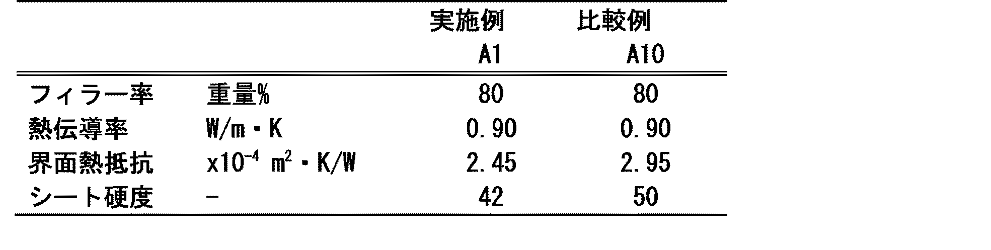
また表1のA1とA10のシリカ粒子を用いて、前述の手順に従って熱伝導シートを作製し、熱伝導率およびシート硬度を測定した。結果を表2に記載する。両者ともにフィラー率80%としたため、フィラー率が支配因子となる熱伝導率はほぼ同じであった。しかし、シート硬度においてA1はA10に比して柔軟であることが分かった。また熱伝導率の測定から得られる上下ブロックとサンプル間の界面熱抵抗をみると、A1はA10に比して低くなっている。これはシート硬度の差によって生じるブロックとの密着性に起因するものと思われる。すなわち、本発明によるシリカ粒子をフィラーとして用いたシリコーン樹脂組成物は、高熱伝導率を得つつ、柔軟性に優れていることが確認された。
Claims (5)
- 光学測定によって撮像される5μm以上の粒子を観察し、撮像から判定される粒子径が以下の条件を満足することを特徴とするシリカ球状粒子。
条件:D99≦29μm、かつ10μm≦Dmode<D99、かつD99/Dmode≦1.5、かつDmode≦20μmであるシリカ球状粒子。 - 請求項1に記載のシリカ球状粒子であって、粒径5μm以上10μm未満の平均円形度が0.98以上、かつ粒径10μm以上20μm未満の平均円形度が0.97以上であることを特徴とするシリカ球状粒子。
- 請求項1乃至2に記載のシリカ球状粒子であって、10~20μmにおけるロジン・ラムラー線図の傾きnが3.5以上であることを特徴とするシリカ球状粒子。
- 請求項1乃至3いずれか1項に記載のシリカ球状粒子であって、レーザー粒度計によって測定される粒径1μm以下の体積比率が2.7%未満であることを特徴とするシリカ球状粒子。
- 請求項1乃至4いずれか1項に記載のシリカ球状粒子であって、BET比表面積が4.0 m2/g未満であるシリカ球状粒子。
Priority Applications (6)
| Application Number | Priority Date | Filing Date | Title |
|---|---|---|---|
| CN201980075006.6A CN113015698A (zh) | 2018-11-13 | 2019-11-13 | 半导体密封材料用二氧化硅球形颗粒 |
| KR1020217013646A KR102579626B1 (ko) | 2018-11-13 | 2019-11-13 | 반도체 밀봉재용 실리카 구상 입자 |
| SG11202104995TA SG11202104995TA (en) | 2018-11-13 | 2019-11-13 | Silica spherical particles for semiconductor sealing material |
| MYPI2021002623A MY204086A (en) | 2018-11-13 | 2019-11-13 | Silica spherical particles for semiconductor sealing material |
| JP2020556144A JP7550649B2 (ja) | 2018-11-13 | 2019-11-13 | 半導体封止材用シリカ球状粒子 |
| US17/293,112 US12145852B2 (en) | 2018-11-13 | 2019-11-13 | Silica spherical particles for semiconductor sealing material |
Applications Claiming Priority (2)
| Application Number | Priority Date | Filing Date | Title |
|---|---|---|---|
| JP2018213267 | 2018-11-13 | ||
| JP2018-213267 | 2018-11-13 |
Publications (1)
| Publication Number | Publication Date |
|---|---|
| WO2020100952A1 true WO2020100952A1 (ja) | 2020-05-22 |
Family
ID=70731808
Family Applications (1)
| Application Number | Title | Priority Date | Filing Date |
|---|---|---|---|
| PCT/JP2019/044586 Ceased WO2020100952A1 (ja) | 2018-11-13 | 2019-11-13 | 半導体封止材用シリカ球状粒子 |
Country Status (8)
| Country | Link |
|---|---|
| US (1) | US12145852B2 (ja) |
| JP (1) | JP7550649B2 (ja) |
| KR (1) | KR102579626B1 (ja) |
| CN (1) | CN113015698A (ja) |
| MY (1) | MY204086A (ja) |
| SG (1) | SG11202104995TA (ja) |
| TW (1) | TWI834757B (ja) |
| WO (1) | WO2020100952A1 (ja) |
Cited By (2)
| Publication number | Priority date | Publication date | Assignee | Title |
|---|---|---|---|---|
| CN111898246A (zh) * | 2020-06-30 | 2020-11-06 | 长江大学 | 一种碎屑沉积物粒度分布拟合及参数计算方法及系统 |
| EP4206132A4 (en) * | 2020-08-25 | 2024-03-13 | Denka Company Limited | AMORPHOUS SILICON DIOXIDE POWDER AND RESIN COMPOSITION THEREFROM |
Families Citing this family (3)
| Publication number | Priority date | Publication date | Assignee | Title |
|---|---|---|---|---|
| TWI744067B (zh) * | 2020-11-02 | 2021-10-21 | 財團法人工業技術研究院 | 粉體圓球化設備 |
| CN113621216B (zh) | 2021-08-16 | 2023-06-02 | 广东生益科技股份有限公司 | 一种树脂组合物及其应用 |
| JP7041788B1 (ja) * | 2021-10-20 | 2022-03-24 | デンカ株式会社 | 球状シリカ粒子及びそれを用いた樹脂組成物 |
Citations (9)
| Publication number | Priority date | Publication date | Assignee | Title |
|---|---|---|---|---|
| JP2001199713A (ja) * | 2000-01-11 | 2001-07-24 | Denki Kagaku Kogyo Kk | 金属酸化物粉末及び樹脂組成物 |
| WO2002026626A1 (en) * | 2000-09-27 | 2002-04-04 | Mitsubishi Rayon Co., Ltd. | Non-porous spherical silica and method for production thereof |
| JP2003110065A (ja) * | 2001-10-01 | 2003-04-11 | Denki Kagaku Kogyo Kk | 球状無機質粉末およびその用途 |
| JP2003267722A (ja) * | 2002-03-12 | 2003-09-25 | Fuso Chemical Co Ltd | 無孔質球状シリカ及びその製造方法 |
| JP2015013789A (ja) * | 2013-04-19 | 2015-01-22 | 株式会社アドマテックス | 分級済粒子材料及びその製造方法、並びに樹脂組成物 |
| JP2015086120A (ja) * | 2013-10-31 | 2015-05-07 | 株式会社トクヤマ | 球状シリカ微粉末とその製造方法 |
| JP2015113277A (ja) * | 2013-12-16 | 2015-06-22 | 旭硝子株式会社 | 球状シリカの製造方法 |
| JP2015149171A (ja) * | 2014-02-06 | 2015-08-20 | 信越化学工業株式会社 | リチウムイオン二次電池用負極材、負極及びリチウムイオン二次電池 |
| JP2018065722A (ja) * | 2016-10-19 | 2018-04-26 | 新日鉄住金マテリアルズ株式会社 | 半導体封止材用球状シリカ質粉末、およびその製造方法 |
Family Cites Families (12)
| Publication number | Priority date | Publication date | Assignee | Title |
|---|---|---|---|---|
| US4767433A (en) * | 1986-05-22 | 1988-08-30 | Asahi Glass Company Ltd. | Spherical silica glass powder particles and process for their production |
| CN1048956C (zh) * | 1996-05-14 | 2000-02-02 | 汪承源 | 二次结晶超细白炭黑的制法 |
| DE19740440A1 (de) | 1997-09-15 | 1999-03-18 | Degussa | Leicht dispergierbare Fällungskieselsäure |
| JP2000003983A (ja) * | 1998-06-16 | 2000-01-07 | Nippon Chem Ind Co Ltd | 液状封止材用溶融球状シリカ及び液状封止樹脂組成物 |
| US6303223B1 (en) * | 1998-06-16 | 2001-10-16 | Nippon Chemical Industrial Co., Ltd. | Fused spherical silica for liquid sealant and liquid sealing resin composition |
| JP2000178413A (ja) * | 1998-12-16 | 2000-06-27 | Tokuyama Corp | 半導体封止材用球状シリカ |
| JP2003137529A (ja) | 2001-10-25 | 2003-05-14 | Denki Kagaku Kogyo Kk | 球状無機質粉末および用途 |
| JP3868272B2 (ja) * | 2001-11-15 | 2007-01-17 | 電気化学工業株式会社 | 球状無機質粉末およびこれを充填した樹脂組成物 |
| GB0525369D0 (en) * | 2005-12-14 | 2006-01-18 | Ineos Silicas Ltd | Silicas |
| JP5199569B2 (ja) | 2006-06-27 | 2013-05-15 | パナソニック株式会社 | 低誘電樹脂組成物、プリプレグ、金属張積層板、プリント配線板 |
| JP6300020B2 (ja) * | 2014-06-16 | 2018-03-28 | パナソニックIpマネジメント株式会社 | プリント配線板用樹脂組成物、プリント配線板用プリプレグ、積層板、金属張積層板、プリント配線板、及び酸化マグネシウム |
| US10421890B2 (en) * | 2016-03-31 | 2019-09-24 | Versum Materials Us, Llc | Composite particles, method of refining and use thereof |
-
2019
- 2019-11-13 SG SG11202104995TA patent/SG11202104995TA/en unknown
- 2019-11-13 MY MYPI2021002623A patent/MY204086A/en unknown
- 2019-11-13 KR KR1020217013646A patent/KR102579626B1/ko active Active
- 2019-11-13 JP JP2020556144A patent/JP7550649B2/ja active Active
- 2019-11-13 TW TW108141276A patent/TWI834757B/zh active
- 2019-11-13 WO PCT/JP2019/044586 patent/WO2020100952A1/ja not_active Ceased
- 2019-11-13 US US17/293,112 patent/US12145852B2/en active Active
- 2019-11-13 CN CN201980075006.6A patent/CN113015698A/zh active Pending
Patent Citations (9)
| Publication number | Priority date | Publication date | Assignee | Title |
|---|---|---|---|---|
| JP2001199713A (ja) * | 2000-01-11 | 2001-07-24 | Denki Kagaku Kogyo Kk | 金属酸化物粉末及び樹脂組成物 |
| WO2002026626A1 (en) * | 2000-09-27 | 2002-04-04 | Mitsubishi Rayon Co., Ltd. | Non-porous spherical silica and method for production thereof |
| JP2003110065A (ja) * | 2001-10-01 | 2003-04-11 | Denki Kagaku Kogyo Kk | 球状無機質粉末およびその用途 |
| JP2003267722A (ja) * | 2002-03-12 | 2003-09-25 | Fuso Chemical Co Ltd | 無孔質球状シリカ及びその製造方法 |
| JP2015013789A (ja) * | 2013-04-19 | 2015-01-22 | 株式会社アドマテックス | 分級済粒子材料及びその製造方法、並びに樹脂組成物 |
| JP2015086120A (ja) * | 2013-10-31 | 2015-05-07 | 株式会社トクヤマ | 球状シリカ微粉末とその製造方法 |
| JP2015113277A (ja) * | 2013-12-16 | 2015-06-22 | 旭硝子株式会社 | 球状シリカの製造方法 |
| JP2015149171A (ja) * | 2014-02-06 | 2015-08-20 | 信越化学工業株式会社 | リチウムイオン二次電池用負極材、負極及びリチウムイオン二次電池 |
| JP2018065722A (ja) * | 2016-10-19 | 2018-04-26 | 新日鉄住金マテリアルズ株式会社 | 半導体封止材用球状シリカ質粉末、およびその製造方法 |
Cited By (2)
| Publication number | Priority date | Publication date | Assignee | Title |
|---|---|---|---|---|
| CN111898246A (zh) * | 2020-06-30 | 2020-11-06 | 长江大学 | 一种碎屑沉积物粒度分布拟合及参数计算方法及系统 |
| EP4206132A4 (en) * | 2020-08-25 | 2024-03-13 | Denka Company Limited | AMORPHOUS SILICON DIOXIDE POWDER AND RESIN COMPOSITION THEREFROM |
Also Published As
| Publication number | Publication date |
|---|---|
| TW202024600A (zh) | 2020-07-01 |
| MY204086A (en) | 2024-08-07 |
| JPWO2020100952A1 (ja) | 2021-10-07 |
| KR102579626B1 (ko) | 2023-09-18 |
| SG11202104995TA (en) | 2021-06-29 |
| KR20210090174A (ko) | 2021-07-19 |
| US12145852B2 (en) | 2024-11-19 |
| CN113015698A (zh) | 2021-06-22 |
| JP7550649B2 (ja) | 2024-09-13 |
| TWI834757B (zh) | 2024-03-11 |
| US20220009783A1 (en) | 2022-01-13 |
Similar Documents
| Publication | Publication Date | Title |
|---|---|---|
| US12145852B2 (en) | Silica spherical particles for semiconductor sealing material | |
| JP6832193B2 (ja) | 樹脂組成物および樹脂封止型半導体装置 | |
| JPH1067883A (ja) | 無機質充填剤及びエポキシ樹脂組成物並びに半導体装置 | |
| JP2022037680A (ja) | 非晶質シリカ粉末及び樹脂組成物 | |
| JP2007277406A (ja) | 高熱伝導性樹脂コンパウンド・高熱伝導性樹脂成形体・放熱シート用配合粒子、高熱伝導性樹脂コンパウンド・高熱伝導性樹脂成形体・放熱シート、および、その製造方法 | |
| JP6712895B2 (ja) | 粉粒状半導体封止用樹脂組成物及び半導体装置 | |
| JP7587977B2 (ja) | 熱伝導性フィラー、及びそれを含有する熱伝導性組成物 | |
| CN113228262A (zh) | 热传导性硅酮组合物和半导体装置 | |
| JP6867540B1 (ja) | 非晶質シリカ粉末及びそれを含有する樹脂組成物 | |
| JPH0680863A (ja) | エポキシ樹脂組成物 | |
| JP2014118461A (ja) | 粉粒状半導体封止用樹脂組成物および半導体装置 | |
| JP2008184584A (ja) | 半導体封止用樹脂組成物およびそれを用いた半導体装置 | |
| JP4244259B2 (ja) | 非晶質シリカ粉末及び樹脂組成物 | |
| JP4634083B2 (ja) | 半導体封止用タブレットの製法 | |
| JP2017053861A (ja) | 粉粒状樹脂組成物の融け性評価方法および樹脂封止型半導体装置の製造方法 | |
| US20200140677A1 (en) | Tablet-type epoxy resin composition for sealing semiconductor device, and semiconductor device sealed using the same | |
| JP4525141B2 (ja) | 半導体封止用エポキシ樹脂組成物の製造方法及びエリア実装型半導体封止用エポキシ樹脂組成物の製造方法 | |
| JP7611365B2 (ja) | 無機酸化物粉末 | |
| JP7002866B2 (ja) | 粉粒状半導体封止用樹脂組成物及び半導体装置 | |
| JPH0841293A (ja) | 封止用エポキシ樹脂組成物及び半導体装置 | |
| JP2022166351A (ja) | 酸化アルミニウム粉末及びその製造方法 | |
| JPH06224328A (ja) | 半導体封止用樹脂組成物 | |
| JP2008184585A (ja) | 半導体封止用樹脂組成物およびそれを用いた半導体装置 | |
| TW202444648A (zh) | 氮化矽粉末及使用其的樹脂組成物 | |
| WO2024048663A1 (ja) | 窒化アルミニウム粉末及び樹脂組成物 |
Legal Events
| Date | Code | Title | Description |
|---|---|---|---|
| 121 | Ep: the epo has been informed by wipo that ep was designated in this application |
Ref document number: 19883774 Country of ref document: EP Kind code of ref document: A1 |
|
| ENP | Entry into the national phase |
Ref document number: 2020556144 Country of ref document: JP Kind code of ref document: A |
|
| NENP | Non-entry into the national phase |
Ref country code: DE |
|
| 122 | Ep: pct application non-entry in european phase |
Ref document number: 19883774 Country of ref document: EP Kind code of ref document: A1 |