WO2020100262A1 - エンジン及び作業機 - Google Patents
エンジン及び作業機 Download PDFInfo
- Publication number
- WO2020100262A1 WO2020100262A1 PCT/JP2018/042329 JP2018042329W WO2020100262A1 WO 2020100262 A1 WO2020100262 A1 WO 2020100262A1 JP 2018042329 W JP2018042329 W JP 2018042329W WO 2020100262 A1 WO2020100262 A1 WO 2020100262A1
- Authority
- WO
- WIPO (PCT)
- Prior art keywords
- piston
- inner peripheral
- cylinder
- spark plug
- engine
- Prior art date
- Legal status (The legal status is an assumption and is not a legal conclusion. Google has not performed a legal analysis and makes no representation as to the accuracy of the status listed.)
- Ceased
Links
Images



Classifications
-
- F—MECHANICAL ENGINEERING; LIGHTING; HEATING; WEAPONS; BLASTING
- F02—COMBUSTION ENGINES; HOT-GAS OR COMBUSTION-PRODUCT ENGINE PLANTS
- F02B—INTERNAL-COMBUSTION PISTON ENGINES; COMBUSTION ENGINES IN GENERAL
- F02B23/00—Other engines characterised by special shape or construction of combustion chambers to improve operation
- F02B23/08—Other engines characterised by special shape or construction of combustion chambers to improve operation with positive ignition
-
- F—MECHANICAL ENGINEERING; LIGHTING; HEATING; WEAPONS; BLASTING
- F02—COMBUSTION ENGINES; HOT-GAS OR COMBUSTION-PRODUCT ENGINE PLANTS
- F02B—INTERNAL-COMBUSTION PISTON ENGINES; COMBUSTION ENGINES IN GENERAL
- F02B23/00—Other engines characterised by special shape or construction of combustion chambers to improve operation
-
- F—MECHANICAL ENGINEERING; LIGHTING; HEATING; WEAPONS; BLASTING
- F02—COMBUSTION ENGINES; HOT-GAS OR COMBUSTION-PRODUCT ENGINE PLANTS
- F02B—INTERNAL-COMBUSTION PISTON ENGINES; COMBUSTION ENGINES IN GENERAL
- F02B23/00—Other engines characterised by special shape or construction of combustion chambers to improve operation
- F02B23/08—Other engines characterised by special shape or construction of combustion chambers to improve operation with positive ignition
- F02B23/10—Other engines characterised by special shape or construction of combustion chambers to improve operation with positive ignition with separate admission of air and fuel into cylinder
- F02B2023/102—Other engines characterised by special shape or construction of combustion chambers to improve operation with positive ignition with separate admission of air and fuel into cylinder the spark plug being placed offset the cylinder centre axis
-
- F—MECHANICAL ENGINEERING; LIGHTING; HEATING; WEAPONS; BLASTING
- F02—COMBUSTION ENGINES; HOT-GAS OR COMBUSTION-PRODUCT ENGINE PLANTS
- F02F—CYLINDERS, PISTONS OR CASINGS, FOR COMBUSTION ENGINES; ARRANGEMENTS OF SEALINGS IN COMBUSTION ENGINES
- F02F3/00—Pistons
- F02F3/26—Pistons having combustion chamber in piston head
-
- Y—GENERAL TAGGING OF NEW TECHNOLOGICAL DEVELOPMENTS; GENERAL TAGGING OF CROSS-SECTIONAL TECHNOLOGIES SPANNING OVER SEVERAL SECTIONS OF THE IPC; TECHNICAL SUBJECTS COVERED BY FORMER USPC CROSS-REFERENCE ART COLLECTIONS [XRACs] AND DIGESTS
- Y02—TECHNOLOGIES OR APPLICATIONS FOR MITIGATION OR ADAPTATION AGAINST CLIMATE CHANGE
- Y02T—CLIMATE CHANGE MITIGATION TECHNOLOGIES RELATED TO TRANSPORTATION
- Y02T10/00—Road transport of goods or passengers
- Y02T10/10—Internal combustion engine [ICE] based vehicles
- Y02T10/12—Improving ICE efficiencies
Definitions
- the present invention relates to an engine and a work machine applicable as a power source of the work machine.
- Patent Document 1 discloses a structure of a combustion chamber formed between inner peripheral surfaces of a cylinder and a cylinder head and an upper surface of a piston.
- the present invention has a structure of a combustion chamber capable of reducing the quench area in the combustion chamber, facilitating the spread of flames in the combustion chamber, and reducing unburned substances remaining unburned in exhaust gas. Provide the engine.
- An engine includes a cylinder block in which a cylinder is formed, a piston arranged so as to be capable of reciprocating in the cylinder, an inner peripheral surface of the cylinder arranged on an upper portion of the cylinder block, and An engine having a cylinder head forming a combustion chamber between the cylinder head and an upper surface of the piston, and an ignition plug arranged in the cylinder head, wherein an inner peripheral portion of the cylinder head has an inner peripheral surface of the cylinder. And an inner peripheral side portion formed so as to be flush with,
- the piston is characterized in that an inclined portion that inclines from an upper surface of the piston toward a side surface is formed.
- the quench area in the combustion chamber can be reduced, and the flame can be easily spread in the combustion chamber. This makes it possible to reduce unburned hydrocarbons (HC) and the like in the exhaust gas.
- HC unburned hydrocarbons
- Sectional drawing which shows the structure of the engine which concerns on embodiment.
- the figure explaining the piston which comprises the engine combustion chamber which concerns on embodiment.
- the figure explaining the combustion chamber structure of the engine which concerns on embodiment.
- the figure explaining the combustion chamber structure of the engine which concerns on a comparative example.
- the bottom view of the cylinder block which concerns on embodiment.
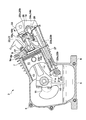
- FIG. 1 is a sectional view showing a configuration of an engine (internal combustion engine) according to the embodiment.
- the engine 3 includes a crankcase 5 having a lower part formed in an oil pan 6, and a cylinder block 7 integrally connected to the upper part of the crankcase 5 and inclined to one side.
- the oil pan 6 is integrally formed with a mounting base 8 so as to project from the outer periphery of the oil pan 6.
- a cylinder head 9 is attached to the upper end of the cylinder block 7, and a head cover 10 is attached to the upper end of the cylinder head 9.
- crankshaft 11 is supported horizontally with respect to the crankcase 5, and the cylinder block 7 is arranged at a position inclined to the right side from the vertical line about the axis of the crankshaft 11. With such an arrangement, the total height of the engine 3 can be kept as low as possible.
- the piston 13 housed in the cylinder 12 formed in the cylinder block 7 and the crank pin 11 a of the crank shaft 11 are connected via the connecting rod 14.
- An oil dipper 15 is formed at the large end of the connecting rod 14, and is configured to scatter the stored oil 16 in the oil pan 6 while the crankshaft 11 is rotating.
- An ignition plug 17 is attached to the cylinder head 9, and an electrode (hereinafter, referred to as a “tip portion”) of the ignition plug 17 projects into the combustion chamber 200 with the ignition plug 17 attached.
- the valve operating device 20 that drives the intake valve 18a and the exhaust valve 18b to open and close is configured as a push rod / rocker arm type. That is, the intake tappet 22a and the exhaust tappet which are respectively lifted and lowered by the intake cam 21a and the exhaust cam 21b which are mounted on the camshaft 21 which is supported by the crankcase 5 and is decelerated from the crankshaft 11 via a timing gear (not shown). 22b, an intake push rod 23a and an exhaust push rod 23b, an intake rocker arm 24a connecting the intake push rod 23a and the exhaust push rod 23b to the intake valve 18a and the exhaust valve 18b, an exhaust rocker arm 24b, and the intake valve 18a and the exhaust gas. It is composed of valve springs 25a and 25b that bias the valve 18b in the closing direction.
- the intake rocker arm 24a and the exhaust rocker arm 24b are housed in the rocker chamber 26 formed between the cylinder head 9 and the head cover 10, and the intake tappet 22a and the exhaust tappet 22b, the intake push rod 23a, and the exhaust push rod 23b are the cylinder block. 7 and the cylinder head 9 are housed in the rod chamber 27 formed in the inclined side wall, that is, the lower side wall.
- the breather pipe 33 connects the rocker chamber 26 to the air cleaner of the intake system (not shown).
- FIG. 2 is a view for explaining the structure of the piston 13 that forms the combustion chamber 200 of the engine 3 according to the embodiment, 2A is a top view of the piston 13, 2B is a side sectional view of the piston 13, and 2C is a broken line of 2B. It is an enlarged view of the part 201.
- the first ring groove 251, the second ring groove 252, and the third ring groove are arranged in this order from the upper surface 13a of the piston 13 downward.
- 253 is provided on the outer peripheral surface (side surface) of the piston 13.
- a portion of the outer peripheral surface (side surface) of the piston 13 from the upper surface 13a of the piston 13 to the upper edge of the first ring groove 251 (upper surface of the first piston ring 261) is called a top land portion 264.
- the piston 13 is formed with an inclined portion 13b inclined from the upper surface 13a of the piston 13 toward the side surface.
- the inclined portion 13b is formed from the upper surface 13a of the piston 13 toward the upper surface of the piston ring (upper surface of the first piston ring 261) mounted at the position closest to the upper surface 13a of the piston 13.
- the diameter D2 of the upper surface 13a of the piston 13 is smaller than the outer diameter D1 of the piston 13, and the inclined portion 13b is formed with a predetermined curvature between the upper surface 13a of the piston and the upper edge of the first ring groove 251. It is composed of curved surfaces.
- the flame propagating in the combustion chamber 200 spreads in the space 265 between the top land portion 264 of the piston 13 and the inner peripheral surface 12a of the cylinder 12, which is the peripheral portion of the combustion chamber 200.
- the quench area can be further reduced by guiding the flame to the space 265 up to the upper surface of the sliding portion (first piston ring 261 (top ring)) with the cylinder 12.
- a recess 266 is formed on the upper surface 13a of the piston 13 at a position facing the tip of the spark plug 17.
- FIG. 3A is a diagram illustrating a structure of a combustion chamber 200 of the engine 3 according to the embodiment
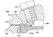
- FIG. 3B is a diagram illustrating a structure of a combustion chamber of an engine according to a comparative example.
- the engine 3 includes a cylinder block 7 in which a cylinder 12 is formed, a piston 13 reciprocally arranged in the cylinder 12, and an upper portion of the cylinder block 7. And a cylinder head 9 that forms a combustion chamber 200 between the inner peripheral surface 12a of the cylinder 12 and the upper surface 13a of the piston 13 that are arranged.
- the spark plug 17 is arranged in the cylinder head 9 at a predetermined inclination angle ⁇ with respect to the axis line 205 (vertical axis line) of the piston 13.
- the inner peripheral portion 9d of the cylinder head 9 has an inner peripheral side portion 9a formed so as to be flush with the inner peripheral surface 12a of the cylinder 12.
- the inner peripheral side portion 9a is extended linearly upward in the vertical direction.
- the structure of the combustion chamber 300 in the comparative example of FIG. 3B has a cylinder block 307 in which the cylinder 312 is formed, and a cylinder head 309 arranged above the cylinder block 307.
- an overhanging portion 303 is formed which juts out in the horizontal direction with respect to the inner peripheral surface of the cylinder 312.
- a gap 305 quenching area
- the flame is cooled in the gap 305, so that the temperature of the flame decreases due to the quenching action, and unburned unburned substances easily remain. ..
- the configuration corresponding to the overhanging portion 303 in the comparative example of FIG. 3B is eliminated, and the inner peripheral side portion that extends the inner peripheral portion 9d of the cylinder head 9 vertically upward 9a is formed.
- the piston 13 is provided with the inclined portion 13b that is inclined from the upper surface 13a of the piston 13 toward the side surface.
- the combustion chamber 200 of the present embodiment having the inner peripheral side portion 9a and the inclined portion 13b, it becomes possible to easily spread the flame in the combustion chamber.
- the air-fuel mixture in the combustion chamber 200 is ignited by the spark ignition by the spark plug 17, and the flame generated thereby spreads radially to the peripheral portion of the combustion chamber 200, that is, the inner peripheral side portion 9a, the inclined portion 13b, and the top land portion. Since it rapidly propagates up to H.264 (2B in FIG. 2), the combustion of the air-fuel mixture in the entire combustion chamber 200 can be carried out quickly and reliably, and the quench area in the combustion chamber can be reduced, thereby reducing the exhaust gas. It becomes possible to reduce unburned hydrocarbons (HC) and the like. That is, by widening the relative distance between the inner peripheral portion of the cylinder head 9 and the piston 13, it is possible to suppress the temperature decrease of the flame due to the quenching action, and to reduce the unburned unburned substances. it can.
- HC unburned hydro
- an arc portion 9b formed in a direction away from the upper surface 13a of the piston 13 is formed at the upper end (upper portion) of the inner peripheral side portion 9a of the cylinder head 9.
- One end of the arc portion 9b is integrally formed with the upper end (upper portion) of the inner peripheral side portion 9a without any step.
- the inner peripheral portion 9d of the cylinder head 9 is located at a position where the tip of the ignition plug 17 projects into the combustion chamber 200, in a direction away from the upper surface 13a of the piston 13 (a direction away from the tip of the ignition plug 17). , And has a concave portion 9c formed in an arc shape.
- One end of the arc portion 9b is integrally formed with the inner peripheral side portion 9a without any step, and the other end of the arc portion 9b is integrally formed with the recess 9c without any step.
- the air-fuel mixture in the combustion chamber 200 is ignited by spark ignition by the spark plug 17, and the flame generated thereby spreads radially.
- the flame caused by contact with the inner peripheral portion 9d of the cylinder head 9 is provided. It is possible to suppress the temperature decrease of 1) and to easily spread the flame into the combustion chamber 200 centering on the tip of the ignition plug 17.
- FIG. 4 is a bottom view of the cylinder head 9 as seen from the electrode side of the ignition plug 17 of the cylinder head 9.
- the ignition plug 17 is arranged in the cylinder head 9 at a predetermined inclination angle ⁇ with respect to the axis 205 (vertical axis), and the depth of the recess 9 c is the inclination of the ignition plug 17. It depends on the direction.
- the depth of the recess 9c is such that the tip of the spark plug 17 is the inner peripheral portion. It is formed to be deeper than the depth of the recess 9c in the direction away from 9d (the direction of arrow B in FIGS. 3A and 4). As shown in FIG. 3A, the depth DP1 of the recess formed on the arrow A side with respect to the tip of the ignition plug 17 is set to be deeper than the depth DP2 of the recess formed on the arrow B side. Has been formed.
- the depth DP1 of the recess 9c is set to be the recess in the direction in which the tip of the spark plug 17 separates from the inner peripheral portion 9d.
- a recess 266 is formed on the upper surface 13 a of the piston 13 at a position facing the tip of the ignition plug 17, and the recess 266 is formed in a direction away from the tip of the ignition plug 17. ing.
- the engine 3 can be applied as a power source for various work machines.
- the working machine is, for example, a cultivator used for cultivating work for cultivating fields or the like, a pump device (water pump) used for various suction / drainage works, and a cleaning work for washing dirt with high-pressure sprayed water.
- the present invention can be applied to a high-pressure washing machine, a spraying device (sprayer) used for spraying chemicals and the like, and a compaction device (compactor) used for compacting work such as pavement surface compaction.
- the engine 3 according to the embodiment as a power source of a working machine (a cultivator, a water pump, a high-pressure washer, a sprayer, a compactor, etc.), unburned substances unburned in exhaust gas, such as hydrocarbons (HC), etc. It is possible to provide a working machine with reduced power consumption.
- a working machine a cultivator, a water pump, a high-pressure washer, a sprayer, a compactor, etc.
- unburned substances unburned in exhaust gas such as hydrocarbons (HC), etc. It is possible to provide a working machine with reduced power consumption.
- the engine of the above embodiment is arranged such that a cylinder (for example, 12 in FIGS. 1 and 3A) in which a cylinder is formed and a cylinder block (for example, 7 in FIGS. 1 and 3A) are reciprocally movable.
- the piston for example, 13 in FIGS. 1 and 3A
- the inner peripheral surface of the cylinder (12) for example, 12a in FIG. 3A
- the piston which are disposed on the cylinder block (7).
- a cylinder head for example, 9 in FIGS. 1 and 3A
- a combustion chamber for example, 200 in FIGS. 1 and 3A
- An engine for example, 3 in FIG. 1 having an ignition plug (for example, 17 in FIGS. 1 and 3A) arranged in the cylinder head (9),
- An inner peripheral portion (for example, 9d in FIG. 3A) of the cylinder head (9) is formed so as to be flush with an inner peripheral surface (12a) of the cylinder (12) (for example, as shown in FIG. 1, 9a) of FIG. 3A,
- the piston (13) is formed with an inclined portion (for example, 13b in FIG. 3A) inclined from the upper surface (for example, 13a in FIGS. 1 and 3A) of the piston toward the side surface.
- the engine of the configuration 1 it is possible to reduce the quench area in the combustion chamber, it is possible to easily spread the flame in the combustion chamber. This makes it possible to reduce unburned hydrocarbons (HC) and the like in the exhaust gas.
- HC unburned hydrocarbons
- the inclined portion (13b) is mounted on the piston ring (for example, the piston ring (13b)) closest to the upper surface (13a) of the piston (13). It is formed toward the upper surface of 261) of 2C of FIG.
- the spark plug (17) is arranged in the cylinder head at a predetermined inclination angle with respect to the axis line of the piston (13), and the depth of the recess (9c) is increased.
- the length varies depending on the direction in which the spark plug is inclined (for example, the arrow A direction and the arrow B direction in FIGS. 3A and 4).
- the depth of the recess (9c) (for example, 3A is deeper than the depth (for example, DP2 of FIG. 3A) of the recessed portion (9c) in the direction in which the tip of the spark plug (17) is separated from the inner peripheral portion (9d).
- the relationship of the depth of the recess 9c satisfies the relationship of DP1> DP2).
- the flame in the direction in which the tip of the spark plug approaches the inner peripheral portion of the cylinder head, the flame easily contacts the inner peripheral portion. Therefore, by forming the depth of the recessed portion in that direction to be deeper than the depth of the recessed portion in the separating direction, the temperature decrease of the flame due to contact with the inner peripheral portion of the cylinder head is suppressed. It becomes possible to easily spread the flame into the combustion chamber, centering on the tip of the spark plug.
- the upper surface (13a) of the piston (13) has a recess (for example, 266 in FIGS. 2 and 3A) at a position facing the tip of the spark plug (17). Has been formed.
- the recess (266) is formed in a direction away from the tip of the spark plug (17).
- the working machine for example, a cultivator, a water pump, a high-pressure washer, a sprayer, a compactor, etc.
- the working machine includes the engine (3) of the above-described embodiment as a power source.
- a working machine of the configuration 10 by using the engine according to the embodiment as a power source of the working machine, a working machine in which unburned unburned substances in exhaust gas, for example, hydrocarbons (HC) and the like are provided. It becomes possible to do.
- exhaust gas for example, hydrocarbons (HC) and the like
Landscapes
- Engineering & Computer Science (AREA)
- Chemical & Material Sciences (AREA)
- Combustion & Propulsion (AREA)
- Mechanical Engineering (AREA)
- General Engineering & Computer Science (AREA)
- Combustion Methods Of Internal-Combustion Engines (AREA)
- Ignition Installations For Internal Combustion Engines (AREA)
Abstract
エンジンは、シリンダが形成されるシリンダブロックと、シリンダ内を往復動可能に配置されたピストンと、シリンダブロックの上部に配置される共にシリンダの内周面およびピストンの上面との間に燃焼室を形成するシリンダヘッドと、シリンダヘッドに配置された点火プラグと、を有する。シリンダヘッドの内周部は、シリンダの内周面と面一になるように形成された内周側部を備え、ピストンは、当該ピストンの上面から側面に向けて傾斜する傾斜部が形成されている。
Description
本発明は、作業機の動力源として適用可能なエンジン及び作業機に関する。
特許文献1には、シリンダおよびシリンダヘッドの内周面およびピストンの上面との間に形成される燃焼室の構造が開示されている。
しかしながら、特許文献1により開示される燃焼室の構造では、ピストンが上死点近傍に位置するとき、シリンダ及びシリンダヘッドの内周部と、ピストンの上面の端部との間に、火炎が伝播しにくい隙間(クエンチエリア)が形成される。
クエンチエリアでは、点火プラグの点火により燃焼室内を火炎が伝播しても、隙間部分では、火炎が冷却されるため、消炎作用による火炎の温度低下が生じ、燃え残りの未燃物質が発生しやすい。
本発明は、上記の課題に鑑み、燃焼室内におけるクエンチエリアを削減し、燃焼室内において火炎を広がりやすくし、排出ガスにおいて燃え残りの未燃物質を低減することが可能な燃焼室の構造を有するエンジンを提供する。
本発明の一つの態様のエンジンは、シリンダが形成されるシリンダブロックと、前記シリンダ内を往復動可能に配置されたピストンと、前記シリンダブロックの上部に配置される共に前記シリンダの内周面および前記ピストンの上面との間に燃焼室を形成するシリンダヘッドと、前記シリンダヘッドに配置された点火プラグと、を有するエンジンであって、前記シリンダヘッドの内周部は、前記シリンダの内周面と面一になるように形成された内周側部を備え、
前記ピストンは、当該ピストンの上面から側面に向けて傾斜する傾斜部が形成されていることを特徴とする。
前記ピストンは、当該ピストンの上面から側面に向けて傾斜する傾斜部が形成されていることを特徴とする。
本発明によれば、燃焼室内におけるクエンチエリアを削減することができ、燃焼室内において火炎を広がりやすくすることが可能になる。これにより排出ガスにおいて未燃の炭化水素(HC)等を低減することが可能になる。
シリンダヘッドの内周部とピストンとの間の相対的な距離を広げることで、消炎作用による火炎の温度低下を抑制することができ、これにより燃え残りの未燃物質を低減することができる。
本発明のその他の特徴及び利点は、添付図面を参照とした以下の説明により明らかになるであろう。なお、添付図面においては、同じ若しくは同様の構成には、同じ参照番号を付す。
以下、図面を参照しながら本発明の実施形態について説明する。この実施形態に記載されている構成要素はあくまで例示であり、以下の実施形態によって限定されるわけではない。
(エンジンの概要)
図1は実施形態に係るエンジン(内燃機関)の構成を示す断面図である。図1に示すように、エンジン3は、下部をオイルパン6に形成したクランクケース5と、クランクケース5の上部に一体に連設されて一側方へ傾斜したシリンダブロック7とを備えており、オイルパン6には、その外周から張出すように据付けベース8が一体に形成されている。シリンダブロック7の上端にはシリンダヘッド9が取付けられ、またシリンダヘッド9の上端にはヘッドカバー10が取付けられている。
図1は実施形態に係るエンジン(内燃機関)の構成を示す断面図である。図1に示すように、エンジン3は、下部をオイルパン6に形成したクランクケース5と、クランクケース5の上部に一体に連設されて一側方へ傾斜したシリンダブロック7とを備えており、オイルパン6には、その外周から張出すように据付けベース8が一体に形成されている。シリンダブロック7の上端にはシリンダヘッド9が取付けられ、またシリンダヘッド9の上端にはヘッドカバー10が取付けられている。
クランク軸11はクランクケース5に対して水平に支持されており、このクランク軸11の軸線を中心としてシリンダブロック7は鉛直線から右側方へ傾斜した位置に配置される。このような配置によりエンジン3の全高を極力低く抑えることが可能になる。
シリンダブロック7に形成されたシリンダ12に収容されるピストン13とクランク軸11のクランクピン11aとはコンロッド14を介して連結されている。コンロッド14の大端部にはオイルディッパ15が形成されており、クランク軸11の回転中、オイルパン6内の貯留オイル16を飛散させるように構成されている。
シリンダヘッド9には点火プラグ17が装着されており、点火プラグ17が装着された状態で、点火プラグ17の電極(以下、「先端部」という)が燃焼室200内に突出する。シリンダヘッド9の内周部には、各一対の吸気弁18a及び排気弁18bがそれぞれ着座し得る吸気弁座22及び排気弁座23が形成されている。
吸気弁18a及び排気弁18bを開閉駆動する動弁装置20はプッシュロッド・ロッカアーム式に構成されている。即ち、クランクケース5に支持されてクランク軸11から図示しないタイミングギヤを介して減速駆動されるカム軸21に装着されている吸気カム21a、排気カム21bによってそれぞれ昇降される吸気タペット22a及び排気タペット22b、吸気プッシュロッド23a及び排気プッシュロッド23b、これら吸気プッシュロッド23a及び排気プッシュロッド23bと吸気弁18a及び排気弁18bとの間を連結する吸気ロッカアーム24a、排気ロッカアーム24b、並びに吸気弁18a及び排気弁18bをそれぞれ閉じ方向へ付勢する弁ばね25a、25bから構成される。
吸気ロッカアーム24a、排気ロッカアーム24bは、シリンダヘッド9及びヘッドカバー10間に形成されるロッカ室26に収容され、また、吸気タペット22a及び排気タペット22b、吸気プッシュロッド23a及び排気プッシュロッド23bは、シリンダブロック7及びシリンダヘッド9の傾斜方向側壁、即ち下側壁に形成されたロッド室27に収容される。図1において、ブリーザパイプ33は、ロッカ室26を図示しない吸気系のエアクリーナ内に連通させる。
(燃焼室の構造)
図2は、実施形態に係るエンジン3の燃焼室200を構成するピストン13の構造を説明する図であり、2Aはピストン13の上面図、2Bはピストン13の側断面図、2Cは2Bの破線部201の拡大図である。
図2は、実施形態に係るエンジン3の燃焼室200を構成するピストン13の構造を説明する図であり、2Aはピストン13の上面図、2Bはピストン13の側断面図、2Cは2Bの破線部201の拡大図である。
図2の2B及び図2Cに示すように、ピストン13の外周面(側面)には、ピストン13の上面13aから下方に向かって順に第1リング溝251、第2リング溝252及び第3リング溝253が設けられている。各リング溝には、シリンダ12の内周面12aに摺動自在に密接する第1ピストンリング261、第2ピストンリング262及び第3ピストンリング263を装着することが可能である。このピストン13の外周面(側面)において、ピストン13の上面13aから第1リング溝251の上縁(第1ピストンリング261の上面)までの部分をトップランド部264と呼ぶ。
ピストン13には、ピストン13の上面13aから側面に向けて傾斜する傾斜部13bが形成されている。この傾斜部13bは、ピストン13の上面13aから、ピストン13の上面13aに対して最も近い位置に装着されているピストンリングの上面(第1ピストンリング261の上面)に向けて形成されている。ピストン13の上面13aの直径D2はピストン13の外径D1に比べて小さく、傾斜部13bは、ピストンの上面13aと、第1リング溝251の上縁との間に所定の曲率で形成された曲面により構成される。
傾斜部13bを形成することにより、燃焼室200の周縁部であるピストン13のトップランド部264とシリンダ12の内周面12aとの間の空間265に、燃焼室200内を伝播する火炎を広がりやすくすることが可能になり、シリンダ12との摺動部(第1ピストンリング261(トップリング))の上面までの空間265へ火炎を導くことで、クエンチエリアを、より削減することが可能になる。
また、図2の2Aに示すように、ピストン13の上面13aには、点火プラグ17の先端部と対向する位置に凹部266が形成されている。凹部266を形成して、点火プラグ17の先端部と、ピストン13における上面13aとの相対的な位置を広げることにより、点火プラグ17の先端部を中心として火炎を燃焼室200内に広がりやすくすることが可能になる。
図3Aは実施形態に係るエンジン3の燃焼室200の構造を説明する図であり、図3Bは、比較例に係るエンジンの燃焼室構造を説明する図である。
図3Aに示すように、燃焼室200の構造として、エンジン3は、シリンダ12が形成されるシリンダブロック7と、シリンダ12内を往復動可能に配置されたピストン13と、シリンダブロック7の上部に配置される共にシリンダ12の内周面12aおよびピストン13の上面13aとの間に燃焼室200を形成するシリンダヘッド9と、を有する。点火プラグ17は、ピストン13の軸線205(鉛直方向の軸線)に対して所定の傾斜角θでシリンダヘッド9に配置されている。
本実施形態の燃焼室200において、シリンダヘッド9の内周部9dは、シリンダ12の内周面12aと面一になるように形成された内周側部9aを有する。この内周側部9aは鉛直上方に直線状に延設されている。
一方、図3Bの比較例における燃焼室300の構造では、シリンダ312が形成されるシリンダブロック307と、シリンダブロック307の上部に配置されシリンダヘッド309と、を有する。
シリンダヘッド309の下面には、シリンダ312の内周面に対して水平方向に張り出した張出部303が形成されており、ピストン313が上死点近傍に位置するとき、張出部303と、ピストン313の上面313aとの間に隙間305(クエンチエリア)が形成される。点火プラグ317の点火により燃焼室300内を火炎が伝播しても、隙間305内では、火炎が冷却されるため、消炎作用による火炎の温度低下が生じ、燃え残りの未燃物質が発生しやすい。
図3Aに示すように本実施形態の燃焼室200では、図3Bの比較例における張出部303に対応する構成を無くし、シリンダヘッド9の内周部9dを鉛直上方に拡張する内周側部9aが形成されている。また、図2で説明したように、ピストン13には、ピストン13の上面13aから側面に向けて傾斜する傾斜部13bが形成されている。
内周側部9a及び傾斜部13bを有する本実施形態の燃焼室200の構造によれば、燃焼室内において火炎を広がりやすくすることが可能になる。点火プラグ17による火花点火により燃焼室200内の混合気が着火され、これによって発生した火炎は放射状に広がり、燃焼室200の周縁部、すなわち、内周側部9a及び傾斜部13bおよびトップランド部264(図2の2B)まで、迅速に伝播するので、燃焼室200の全体で混合気の燃焼が迅速、確実に行われ、燃焼室内におけるクエンチエリアを削減することができ、これにより排出ガスにおいて未燃の炭化水素(HC)等を低減することが可能になる。すなわち、シリンダヘッド9の内周部とピストン13との間の相対的な距離を広げることで、消炎作用による火炎の温度低下を抑制することができ、燃え残りの未燃物質を低減することができる。
また、本実施形態の燃焼室200において、シリンダヘッド9の内周側部9aの上端(上部)には、ピストン13の上面13aから離間する方向に形成された円弧部9bが形成されている。円弧部9bの一端は内周側部9aの上端(上部)と段差の無い状態で一体に形成されている。内周側部9aの上端に円弧部9bを形成することにより、シリンダヘッド9側における火炎の広がりを円滑にし、燃焼室200の周縁部(内周側部9a及び傾斜部13bおよびトップランド部264)において火炎を広がりやすくすることが可能になる。
また、シリンダヘッド9の内周部9dは、点火プラグ17の先端部が燃焼室200に突出する位置に、ピストン13の上面13aから離間する方向(点火プラグ17の先端部から離間する方向)に、円弧状に形成された窪み部9cを有する。円弧部9bの一端は内周側部9aと段差無く一体に形成されており、円弧部9bの他端は窪み部9cと段差無く一体に形成されている。
点火プラグ17による火花点火により燃焼室200内の混合気が着火され、これによって発生した火炎は放射状に広がるが、窪み部9cを設けることにより、シリンダヘッド9の内周部9dとの接触による火炎の温度低下を抑制し、点火プラグ17の先端部を中心として火炎を燃焼室200内に広がりやすくすることが可能になる。
図4は、シリンダヘッド9を点火プラグ17の電極側から見たシリンダヘッド9の下面図である。点火プラグ17は、図3Aで示したように軸線205(鉛直方向の軸線)に対して所定の傾斜角θでシリンダヘッド9に配置されており、窪み部9cの深さは点火プラグ17の傾斜する方向に応じて異なる。
点火プラグ17の先端部がシリンダヘッド9の内周部9dに近づく方向(図3A及び図4の矢印Aの方向)では、窪み部9cの深さは、点火プラグ17の先端部が内周部9dから離間する方向(図3A及び図4の矢印Bの方向)における窪み部9cの深さに比べて深くなるように形成されている。図3Aに示すように点火プラグ17の先端部を基準として矢印A側に形成される窪み部の深さDP1は、矢印B側に形成される窪み部の深さDP2に比べて深くなるように形成されている。
点火プラグ17の先端部がシリンダヘッド9の内周部に近づく方向(矢印Aの方向)では、点火プラグ17による火花点火により発生した火炎は内周部9dに接触しやすくなる。このため、点火プラグ17の先端部がシリンダヘッド9の内周部9dに近づく方向では、窪み部9cの深さDP1を、点火プラグ17の先端部が内周部9dから離間する方向における窪み部9cの深さDP2に比べて、より深く形成する(すなわち、窪み部9cの深さの関係がDP1>DP2を満たす)ことにより、シリンダヘッド9の内周部9dとの接触による火炎の温度低下を抑制し、点火プラグ17の先端部を中心として火炎を燃焼室200内に広がりやすくすることが可能になる。
図3Aに示すように、ピストン13の上面13aには、点火プラグ17の先端部と対向する位置に凹部266が形成されており、凹部266は点火プラグ17の先端部から離間する方向に形成されている。点火プラグ17の先端部とピストン13の上面13aとの相対的な位置(間隔)を広げることにより、点火プラグ17の先端部を中心として火炎を燃焼室200内に広がりやすくすることが可能になる。
図3Aに示すように、ピストン13が上死点の位置または上死点近傍の位置にあるとき、シリンダヘッド9の窪み部9cとピストン13の凹部266との間には、破線で示すような略球状の空間280が燃焼室200内に形成される。このような燃焼室200の構造によれば、点火プラグ17による火花点火により燃焼室200内の混合気が着火されると、発生した火炎は放射状に広がり、燃焼室200内において、点火プラグ17を中心として広がる放射状の火炎を形成することが可能になる。
エンジン3は、種々の作業機の動力源として適用可能である。作業機としは、例えば、田畑等を耕す耕作作業等に用いられる耕運機、各種の吸・排水作業等に用いられるポンプ装置(水ポンプ)、高圧で噴射した水で汚れを洗い流す洗浄作業に用いられる高圧洗浄機、薬剤等を散布する散布作業に用いられる散布装置(スプレーヤ)、舗装面等の締固めを行う転圧作業に用いられる転圧装置(コンパクター)等に適用可能である。
実施形態に係るエンジン3を作業機(耕運機、水ポンプ、高圧洗浄機、スプレーヤ、コンパクター等)の動力源として用いることにより、排出ガスにおいて燃え残りの未燃物質、例えば、炭化水素(HC)等を低減した作業機を提供することが可能になる。
<実施形態のまとめ>
構成1.上記実施形態のエンジンは、シリンダ(例えば、図1、図3Aの12)が形成されるシリンダブロック(例えば、図1、図3Aの7)と、前記シリンダ(12)内を往復動可能に配置されたピストン(例えば、図1、図3Aの13)と、前記シリンダブロック(7)の上部に配置される共に前記シリンダ(12)の内周面(例えば、図3Aの12a)および前記ピストン(13)の上面(例えば、図1、図3Aの13a)との間に燃焼室(例えば、図1、図3Aの200)を形成するシリンダヘッド(例えば、図1、図3Aの9)と、前記シリンダヘッド(9)に配置された点火プラグ(例えば、図1、図3Aの17)と、を有するエンジン(例えば、図1の3)であって、
前記シリンダヘッド(9)の内周部(例えば、図3Aの9d)は、前記シリンダ(12)の内周面(12a)と面一になるように形成された内周側部(例えば、図1、図3Aの9a)を備え、
前記ピストン(13)は、当該ピストンの上面(例えば、図1、図3Aの13a)から側面に向けて傾斜する傾斜部(例えば、図3Aの13b)が形成されている。
構成1.上記実施形態のエンジンは、シリンダ(例えば、図1、図3Aの12)が形成されるシリンダブロック(例えば、図1、図3Aの7)と、前記シリンダ(12)内を往復動可能に配置されたピストン(例えば、図1、図3Aの13)と、前記シリンダブロック(7)の上部に配置される共に前記シリンダ(12)の内周面(例えば、図3Aの12a)および前記ピストン(13)の上面(例えば、図1、図3Aの13a)との間に燃焼室(例えば、図1、図3Aの200)を形成するシリンダヘッド(例えば、図1、図3Aの9)と、前記シリンダヘッド(9)に配置された点火プラグ(例えば、図1、図3Aの17)と、を有するエンジン(例えば、図1の3)であって、
前記シリンダヘッド(9)の内周部(例えば、図3Aの9d)は、前記シリンダ(12)の内周面(12a)と面一になるように形成された内周側部(例えば、図1、図3Aの9a)を備え、
前記ピストン(13)は、当該ピストンの上面(例えば、図1、図3Aの13a)から側面に向けて傾斜する傾斜部(例えば、図3Aの13b)が形成されている。
構成1のエンジンによれば、燃焼室内におけるクエンチエリアを削減することができ、燃焼室内において火炎を広がりやすくすることが可能になる。これにより排出ガスにおいて未燃の炭化水素(HC)等を低減することが可能になる。
シリンダヘッドの内周部とピストンとの間の相対的な距離を広げることで、消炎作用による火炎の温度低下を抑制することができ、これにより燃え残りの未燃物質を低減することができる。
構成2.上記実施形態のエンジン(3)では、前記傾斜部(13b)は、前記ピストン(13)の上面(13a)から、前記ピストンの上面に対して最も近い位置に装着されているピストンリング(例えば、図2の2Cの261)の上面に向けて形成されている。
構成2のエンジンによれば、シリンダとの摺動部(ピストンリング(トップリング))の上面までの空間へ火炎を導くことで、クエンチエリアを、より削減することが可能になる。
構成3.上記実施形態のエンジン(3)では、前記内周側部(9a)の上端には、前記ピストン(13)の上面(13a)から離間する方向に形成された円弧部(例えば、図1、図3Aの9b)が形成されている。
構成3のエンジンによれば、内周側部の上端に円弧部を形成することにより、シリンダヘッド側における火炎の広がりを円滑にし、内周側部の周辺において火炎を広がりやすくすることが可能になる。
構成4.上記実施形態のエンジン(3)では、前記シリンダヘッド(9)の内周部(例えば、図3A、図4の9d)は、前記点火プラグ(17)の先端部が前記燃焼室(200)に突出する位置に、円弧状に形成された窪み部(例えば、図3A、図4の9c)を有する。
構成4のエンジンによれば、窪み部を設けることにより、シリンダヘッドの内周部との接触による火炎の温度低下を抑制し、点火プラグを中心として火炎を燃焼室内に広がりやすくすることが可能になる。
構成5.上記実施形態のエンジン(3)では、前記点火プラグ(17)は、前記ピストン(13)の軸線に対して所定の傾斜角で前記シリンダヘッドに配置されており、前記窪み部(9c)の深さは前記点火プラグの傾斜する方向(例えば、図3A、図4の矢印A方向、矢印B方向)に応じて異なる。
構成5のエンジンによれば、点火プラグの傾斜する方向に応じて窪み部の深さが異なるようにシリンダヘッドを形成することにより、シリンダヘッドの内周部との接触による火炎の温度低下を抑制し、点火プラグを中心として火炎を燃焼室内に広がりやすくすることが可能になる。
構成6.上記実施形態のエンジン(3)では、前記点火プラグ(17)の先端部が前記シリンダヘッド(9)の内周部(9d)に近づく方向では、前記窪み部(9c)の深さ(例えば、図3AのDP1)は、前記点火プラグ(17)の先端部が前記内周部(9d)から離間する方向における前記窪み部(9c)の深さ(例えば、図3AのDP2)に比べて深くなる(例えば、窪み部9cの深さの関係がDP1>DP2の関係を満たす)ように形成されている。
構成6のエンジンによれば、点火プラグの先端部が前記シリンダヘッドの内周部に近づく方向では、火炎は内周部に接触しやすくなる。このため、当該方向では窪み部の深さを、離間する方向における窪み部の深さに比べて、より深く形成することにより、シリンダヘッドの内周部との接触による火炎の温度低下を抑制し、点火プラグの先端部を中心として火炎を燃焼室内に広がりやすくすることが可能になる。
構成7.上記実施形態のエンジン(3)では、前記ピストン(13)の上面(13a)には、前記点火プラグ(17)の先端部と対向する位置に凹部(例えば、図2、図3Aの266)が形成されている。
構成7のエンジンによれば、点火プラグの先端部とピストン上面との相対的な位置を広げることにより、点火プラグを中心として火炎を燃焼室内に広がりやすくすることが可能になる。
構成8.上記実施形態のエンジン(3)では、前記凹部(266)は前記点火プラグ(17)の先端部から離間する方向に形成されている。
構成8のエンジンによれば、点火プラグの先端部とピストン上面との相対的な位置を広げることにより、点火プラグを中心として火炎を燃焼室内に広がりやすくすることが可能になる。
構成9.上記実施形態のエンジン(3)では、前記ピストン(13)が上死点の位置にあるとき、前記窪み部(9c)と前記凹部(266)との間には略球状の空間(例えば、図3Aの280)が前記燃焼室(200)内に形成される。
構成9のエンジンによれば、燃焼室内において、点火プラグを中心として広がる火炎を形成することが可能になる。
構成10.上記実施形態の作業機(例えば、耕運機、水ポンプ、高圧洗浄機、スプレーヤ、コンパクター等)は、動力源として上記実施形態のエンジン(3)を備える。
構成10の作業機によれば、実施形態に係るエンジンを作業機の動力源として用いることにより、排出ガスにおいて燃え残りの未燃物質、例えば、炭化水素(HC)等を低減した作業機を提供することが可能になる。
本発明は上記実施の形態に制限されるものではなく、本発明の精神及び範囲から離脱することなく、様々な変更及び変形が可能である。従って、本発明の範囲を公にするために、以下の請求項を添付する。
3:エンジン、7:シリンダブロック、9:シリンダヘッド、9a:内周側部、9b:円弧部、9c:窪み部、9d:シリンダヘッドの内周部、12:シリンダ、12a:シリンダの内周面、13:ピストン、13a:ピストンの上面、13b:傾斜部、266:ピストンの凹部、17:点火プラグ
Claims (10)
- シリンダが形成されるシリンダブロックと、前記シリンダ内を往復動可能に配置されたピストンと、前記シリンダブロックの上部に配置される共に前記シリンダの内周面および前記ピストンの上面との間に燃焼室を形成するシリンダヘッドと、前記シリンダヘッドに配置された点火プラグと、を有するエンジンであって、
前記シリンダヘッドの内周部は、前記シリンダの内周面と面一になるように形成された内周側部を備え、
前記ピストンは、当該ピストンの上面から側面に向けて傾斜する傾斜部が形成されていることを特徴とするエンジン。 - 前記傾斜部は、前記ピストンの上面から、前記ピストンの上面に対して最も近い位置に装着されているピストンリングの上面に向けて形成されていることを特徴とする請求項1に記載のエンジン。
- 前記内周側部の上端には、前記ピストンの上面から離間する方向に形成された円弧部が形成されていることを特徴とする請求項1又は2に記載のエンジン。
- 前記シリンダヘッドの内周部は、前記点火プラグの先端部が前記燃焼室に突出する位置に、円弧状に形成された窪み部を有することを特徴とする請求項1乃至3のいずれか1項に記載のエンジン。
- 前記点火プラグは、前記ピストンの軸線に対して所定の傾斜角で前記シリンダヘッドに配置されており、
前記窪み部の深さは前記点火プラグの傾斜する方向に応じて異なることを特徴とする請求項4に記載のエンジン。 - 前記点火プラグの先端部が前記シリンダヘッドの内周部に近づく方向では、前記窪み部の深さは、前記内周部から離間する方向における前記窪み部の深さに比べて深くなるように形成されていることを特徴とする請求項4または5に記載のエンジン。
- 前記ピストンの上面には、前記点火プラグの先端部と対向する位置に凹部が形成されていることを特徴とする請求項4乃至6のいずれか1項に記載のエンジン。
- 前記凹部は前記点火プラグの先端部から離間する方向に形成されていることを特徴とする請求項7に記載のエンジン。
- 前記ピストンが上死点の位置にあるとき、前記窪み部と前記凹部との間には略球状の空間が前記燃焼室内に形成されることを特徴とする請求項7又は8に記載のエンジン。
- 請求項1乃至9のいずれか1項に記載のエンジンを動力源として備えることを特徴とする作業機。
Priority Applications (2)
| Application Number | Priority Date | Filing Date | Title |
|---|---|---|---|
| PCT/JP2018/042329 WO2020100262A1 (ja) | 2018-11-15 | 2018-11-15 | エンジン及び作業機 |
| US17/314,391 US11674473B2 (en) | 2018-11-15 | 2021-05-07 | Engine and work machine |
Applications Claiming Priority (1)
| Application Number | Priority Date | Filing Date | Title |
|---|---|---|---|
| PCT/JP2018/042329 WO2020100262A1 (ja) | 2018-11-15 | 2018-11-15 | エンジン及び作業機 |
Related Child Applications (1)
| Application Number | Title | Priority Date | Filing Date |
|---|---|---|---|
| US17/314,391 Continuation US11674473B2 (en) | 2018-11-15 | 2021-05-07 | Engine and work machine |
Publications (1)
| Publication Number | Publication Date |
|---|---|
| WO2020100262A1 true WO2020100262A1 (ja) | 2020-05-22 |
Family
ID=70731396
Family Applications (1)
| Application Number | Title | Priority Date | Filing Date |
|---|---|---|---|
| PCT/JP2018/042329 Ceased WO2020100262A1 (ja) | 2018-11-15 | 2018-11-15 | エンジン及び作業機 |
Country Status (2)
| Country | Link |
|---|---|
| US (1) | US11674473B2 (ja) |
| WO (1) | WO2020100262A1 (ja) |
Cited By (1)
| Publication number | Priority date | Publication date | Assignee | Title |
|---|---|---|---|---|
| US11674473B2 (en) | 2018-11-15 | 2023-06-13 | Honda Motor Co., Ltd. | Engine and work machine |
Citations (4)
| Publication number | Priority date | Publication date | Assignee | Title |
|---|---|---|---|---|
| US4508073A (en) * | 1982-06-30 | 1985-04-02 | Dr. Ing. H.C.F. Porsche A.G. | Combustion space of a piston driven internal combustion engine |
| JP2004245204A (ja) * | 2003-02-17 | 2004-09-02 | Mitsubishi Motors Corp | 内燃機関の燃料噴射装置 |
| JP2005140005A (ja) * | 2003-11-06 | 2005-06-02 | Nissan Motor Co Ltd | 筒内直接噴射式内燃機関 |
| JP2016121638A (ja) * | 2014-12-25 | 2016-07-07 | マツダ株式会社 | 直噴エンジンの燃焼室構造 |
Family Cites Families (14)
| Publication number | Priority date | Publication date | Assignee | Title |
|---|---|---|---|---|
| IT1110791B (it) * | 1979-03-08 | 1986-01-06 | Alfa Romeo Spa | Camera di combustione per motore a scoppio |
| GB2070135B (en) * | 1980-02-12 | 1984-02-01 | Nissan Motor | Spark-ignition internal combustion engine |
| JPS5822421U (ja) | 1981-08-04 | 1983-02-12 | 株式会社クボタ | デイ−ゼルエンジンの直接噴射式燃焼室 |
| JPS58170820A (ja) * | 1982-03-31 | 1983-10-07 | Sanshin Ind Co Ltd | 2サイクル内燃機関 |
| US4570589A (en) * | 1982-08-09 | 1986-02-18 | Regents Of The University Of Minnesota | Method for reducing damage associated with detonation and/or destructive knock |
| US5873341A (en) * | 1993-10-29 | 1999-02-23 | Autosales, Incorporated | High performance head assembly for an internal combustion engine |
| JP3763491B2 (ja) * | 1996-10-08 | 2006-04-05 | 富士重工業株式会社 | 筒内噴射エンジンの燃焼室構造 |
| US6338327B1 (en) * | 1999-03-29 | 2002-01-15 | Fuji Jukogyo Kabushiki Kaisha | Combustion chamber structure of in-cylinder direct fuel injection engine |
| DE10026324A1 (de) * | 2000-05-26 | 2001-11-29 | Bosch Gmbh Robert | Brennstoffeinspritzsystem |
| US6892693B2 (en) * | 2003-02-12 | 2005-05-17 | Bombardier Recreational Products, Inc. | Piston for spark-ignited direct fuel injection engine |
| US7353797B1 (en) * | 2007-02-28 | 2008-04-08 | University Of Washington | Combustion chamber for internal combustion engine |
| JP5922569B2 (ja) * | 2012-12-28 | 2016-05-24 | 株式会社マキタ | 層状掃気2ストロークエンジン |
| JP6841245B2 (ja) * | 2018-01-25 | 2021-03-10 | トヨタ自動車株式会社 | 内燃機関 |
| WO2020100262A1 (ja) | 2018-11-15 | 2020-05-22 | 本田技研工業株式会社 | エンジン及び作業機 |
-
2018
- 2018-11-15 WO PCT/JP2018/042329 patent/WO2020100262A1/ja not_active Ceased
-
2021
- 2021-05-07 US US17/314,391 patent/US11674473B2/en active Active
Patent Citations (4)
| Publication number | Priority date | Publication date | Assignee | Title |
|---|---|---|---|---|
| US4508073A (en) * | 1982-06-30 | 1985-04-02 | Dr. Ing. H.C.F. Porsche A.G. | Combustion space of a piston driven internal combustion engine |
| JP2004245204A (ja) * | 2003-02-17 | 2004-09-02 | Mitsubishi Motors Corp | 内燃機関の燃料噴射装置 |
| JP2005140005A (ja) * | 2003-11-06 | 2005-06-02 | Nissan Motor Co Ltd | 筒内直接噴射式内燃機関 |
| JP2016121638A (ja) * | 2014-12-25 | 2016-07-07 | マツダ株式会社 | 直噴エンジンの燃焼室構造 |
Cited By (1)
| Publication number | Priority date | Publication date | Assignee | Title |
|---|---|---|---|---|
| US11674473B2 (en) | 2018-11-15 | 2023-06-13 | Honda Motor Co., Ltd. | Engine and work machine |
Also Published As
| Publication number | Publication date |
|---|---|
| US20210262413A1 (en) | 2021-08-26 |
| US11674473B2 (en) | 2023-06-13 |
Similar Documents
| Publication | Publication Date | Title |
|---|---|---|
| US4125265A (en) | Valve stem seal | |
| US5771872A (en) | Combustion chamber of an internal combustion engine | |
| WO2020100262A1 (ja) | エンジン及び作業機 | |
| JP2012215138A (ja) | 内燃機関用ピストンのオイル供給装置 | |
| JP2016217202A (ja) | 内燃機関 | |
| JP3982482B2 (ja) | 筒内直接噴射式内燃機関の燃焼室構造 | |
| JP2001059422A (ja) | 火花点火式の四弁型内燃機関の構造 | |
| RU104246U1 (ru) | Поршень для двигателя внутреннего сгорания (варианты) | |
| JP2006275002A (ja) | 内燃機関用ピストン | |
| JP6060126B2 (ja) | 内燃機関 | |
| JP5781680B1 (ja) | 内燃機関 | |
| JP4609708B2 (ja) | 火花点火式直噴エンジン | |
| US12085038B2 (en) | Internal combustion engine | |
| JPS6220686Y2 (ja) | ||
| KR20200117283A (ko) | 엔진 유닛 | |
| RU186419U1 (ru) | Поршень дизельного двигателя внутреннего сгорания | |
| JP4216944B2 (ja) | 内燃機関の燃焼室構造 | |
| KR200148920Y1 (ko) | 오일 링홈에 단턱을 형성한 피스톤 | |
| JP2022105620A (ja) | 内燃機関 | |
| JPH08284747A (ja) | ピストン機関 | |
| JP2013181493A (ja) | ピストン | |
| KR200212883Y1 (ko) | 디젤엔진용 피스톤 | |
| JP2015169199A (ja) | 2ストロークエンジンのシリンダ潤滑装置 | |
| JP2016186295A (ja) | 内燃機関 | |
| KR19990042865A (ko) | 소음 방지용 피스톤 스커트 |
Legal Events
| Date | Code | Title | Description |
|---|---|---|---|
| 121 | Ep: the epo has been informed by wipo that ep was designated in this application |
Ref document number: 18940371 Country of ref document: EP Kind code of ref document: A1 |
|
| NENP | Non-entry into the national phase |
Ref country code: DE |
|
| 122 | Ep: pct application non-entry in european phase |
Ref document number: 18940371 Country of ref document: EP Kind code of ref document: A1 |
|
| NENP | Non-entry into the national phase |
Ref country code: JP |